

Mitsubishi CR760-Q, CR751-Q, CR750-Q, CR750-D, CR751-D Instruction Manual
...
Mitsubishi Industrial Robot
CR750/CR751/CR760 Series Controller
INSTRUCTION MANUAL
Troubleshooting
This instruction manual apply to both the CR-750-Q/CR751-Q/CR760-Q controller corresponding
to iQ Platform, and the CR-750-D/CR751-D/CR760-D controller of standalone type.
BFP-A8871-U


All teaching work must be carried out by an operator who has received special
Always read the following precautions and the separate "Safety
Manual" before starting use of the robot to learn the required
measures to be taken.
Safety Precautions
CAUTION
CAUTION
WARNING
CAUTION
DANGER
CAUTION
CAUTION
CAUTION
training. (This also applies to maintenance work with the power source turned
ON.)
Enforcement of safety training
For teaching work, prepare a work plan related to the methods and procedures
of operating the robot, and to the measures to be taken when an error occurs
or when restarting. Carry out work following this plan. (This also applies to
maintenance work with the power source turned ON.)
Preparation of work plan
Prepare a device that allows operation to be stopped immediately during
teaching work. (This also applies to maintenance work with the power source
turned ON.)
Setting of emergency stop switch
During teaching work, place a sign indicating that teaching work is in progress
on the start switch, etc. (This also applies to maintenance work with the power
source turned ON.)
Indication of teaching work in progress
Provide a fence or enclosure during operation to prevent contact of the
operator and robot.
Installation of safety fence
Establish a set signaling method to the related operators for starting work, and
follow this method.
Signaling of operation start
As a principle turn the power OFF during maintenance work. Place a sign
indicating that maintenance work is in progress on the start switch, etc.
Indication of maintenance work in progress
Before starting work, inspect the robot, emergency stop switch and other
related devices, etc., and confirm that there are no errors.
Inspection before starting work
The points of the precautions given in the separate "Safety Manual" are given below.
DANGER
CAUTION
CAUTION
CAUTION
CAUTION
CAUTION
CAUTION
WARNING
WARNING
CAUTION
WARNING
CAUTION
CAUTION
CAUTION
CAUTION
Refer to the actual "Safety Manual" for details.
When automatic operation of the robot is performed using multiple control
devices (GOT, programmable controller, push-button switch), the interlocking of
operation rights of the devices, etc. must be designed by the customer.
Use the robot within the environment given in the specifications. Failure to do
so could lead to a drop or reliability or faults. (Temperature, humidity,
atmosphere, noise environment, etc.)
Transport the robot with the designated transportation posture. Transporting
the robot in a non-designated posture could lead to personal injuries or faults
from dropping.
Always use the robot installed on a secure table. Use in an instable posture
could lead to positional deviation and vibration.
Wire the cable as far away from noise sources as possible. If placed near a noise
source, positional deviation or malfunction could occur.
Do not apply excessive force on the connector or excessively bend the cable.
Failure to observe this could lead to contact defects or wire breakage.
Make sure that the workpiece weight, including the hand, does not exceed the
rated load or tolerable torque. Exceeding these values could lead to alarms or
faults.
Securely install the hand and tool, and securely grasp the workpiece. Failure to
observe this could lead to personal injuries or damage if the object comes off or
flies off during operation.
Securely ground the robot and controller. Failure to observe this could lead to
malfunctioning by noise or to electric shock accidents.
Indicate the operation state during robot operation. Failure to indicate the state
could lead to operators approaching the robot or to incorrect operation.
When carrying out teaching work in the robot's movement range, always secure
the priority right for the robot control. Failure to observe this could lead to
personal injuries or damage if the robot is started with external commands.
Keep the jog speed as low as possible, and always watch the robot. Failure to do
so could lead to interference with the workpiece or peripheral devices.
After editing the program, always confirm the operation with step operation
before starting automatic operation. Failure to do so could lead to interference
with peripheral devices because of programming mistakes, etc.
Make sure that if the safety fence entrance door is opened during automatic
operation, the door is locked or that the robot will automatically stop. Failure to
do so could lead to personal injuries.
Never carry out modifications based on personal judgments, or use nondesignated maintenance parts.
Failure to observe this could lead to faults or failures.
When the robot arm has to be moved by hand from an external area, do not
WARNING
CAUTION
CAUTION
DANGER
DANGER
DANGER
DANGER
DANGER
CAUTION
place hands or fingers in the openings. Failure to observe this could lead to
hands or fingers catching depending on the posture.
Do not stop the robot or apply emergency stop by turning the robot controller's
main power OFF. If the robot controller main power is turned OFF during
automatic operation, the robot accuracy could be adversely affected. Moreover,
it may interfere with the peripheral device by drop or move by inertia of the arm.
Do not turn off the main power to the robot controller while rewriting the
internal information of the robot controller such as the program or parameters.
If the main power to the robot controller is turned off while in automatic
operation or rewriting the program or parameters, the internal information of the
robot controller may be damaged.
Do not connect the Handy GOT when using the GOT direct connection function
of this product. Failure to observe this may result in property damage or bodily
injury because the Handy GOT can automatically operate the robot regardless
of whether the operation rights are enabled or not.
Do not connect the Handy GOT to a programmable controller when using an iQ
Platform compatible product with the CR7xx-Q controller. Failure to observe
this may result in property damage or bodily injury because the Handy GOT can
automatically operate the robot regardless of whether the operation rights are
enabled or not.
Do not remove the SSCNET III cable while power is supplied to the multiple
CPU system or the servo amplifier. Do not look directly at light emitted from
the tip of SSCNET III connectors or SSCNET III cables of the Motion CPU or
the servo amplifier. Eye discomfort may be felt if exposed to the light.
(Reference: SSCNET III employs a Class 1 or equivalent light source as
specified in JIS C 6802 and IEC60825-1 (domestic standards in Japan).)
Do not remove the SSCNET III cable while power is supplied to the controller.
Do not look directly at light emitted from the tip of SSCNET III connectors or
SSCNET III cables. Eye discomfort may be felt if exposed to the light.
(Reference: SSCNET III employs a Class 1 or equivalent light source as
specified in JIS C 6802 and IEC60825-1 (domestic standards in Japan).)
Attach the cap to the SSCNET III connector after disconnecting the SSCNET
III cable. If the cap is not attached, dirt or dust may adhere to the connector
pins, resulting in deterioration connector properties, and leading to malfunction.
Make sure there are no mistakes in the wiring. Connecting differently to the way
specified in the manual can result in errors, such as the emergency stop not
being released. In order to prevent errors occurring, please be sure to check
that all functions (such as the teaching box emergency stop, customer emer
gency stop, and door switch) are working properly after the wiring setup is com
pleted.
-
-

Use the network equipments (personal computer, USB hub, LAN hub, etc)
CAUTION
confirmed by manufacturer. The thing unsuitable for the FA environment
(related with conformity, temperature or noise) exists in the equipments
connected to USB. When using network equipment, measures against the noise,
such as measures against EMI and the addition of the ferrite core, may be
necessary. Please fully confirm the operation by customer. Guarantee and
maintenance of the equipment on the market (usual office automation
equipment) cannot be performed.
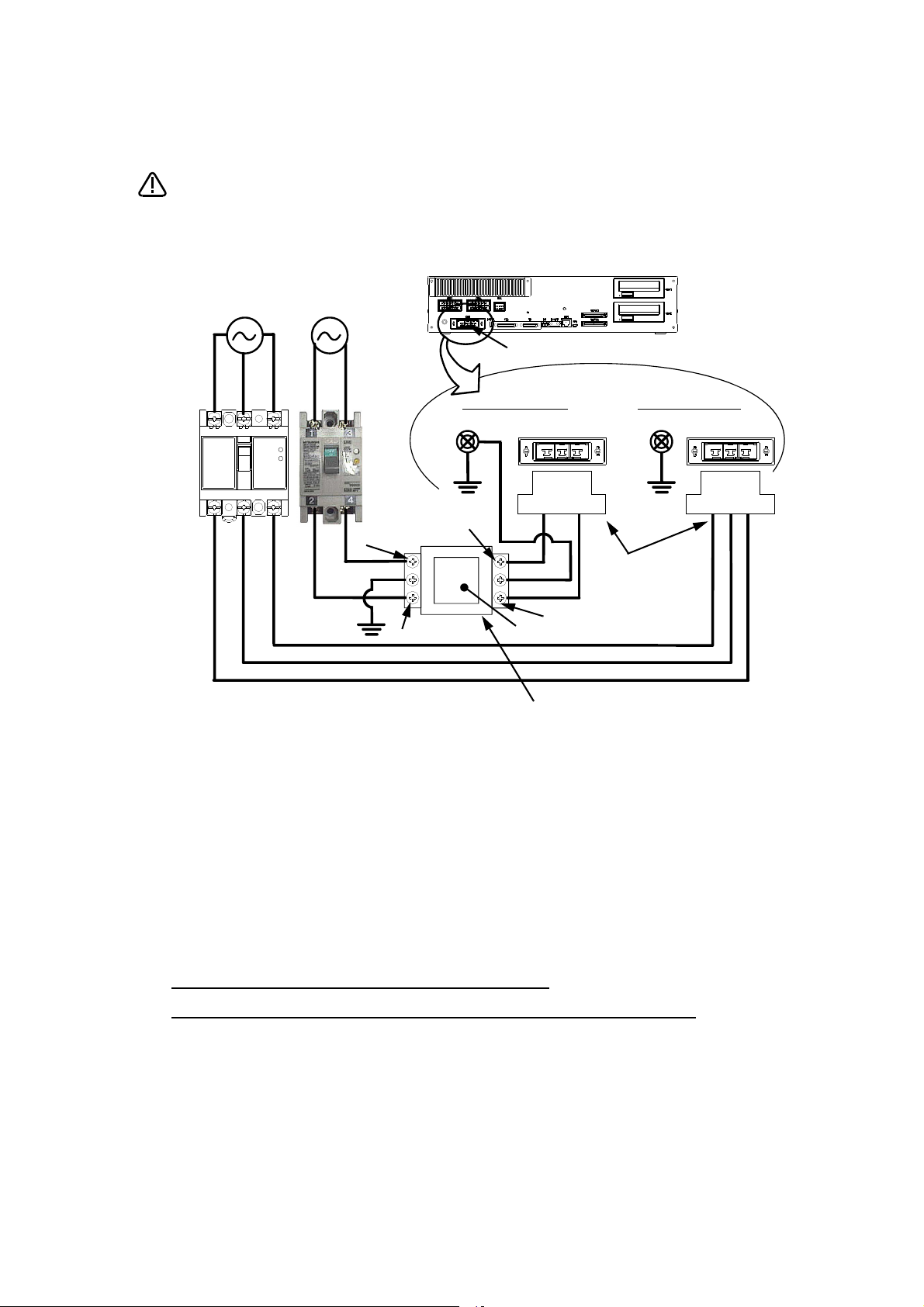
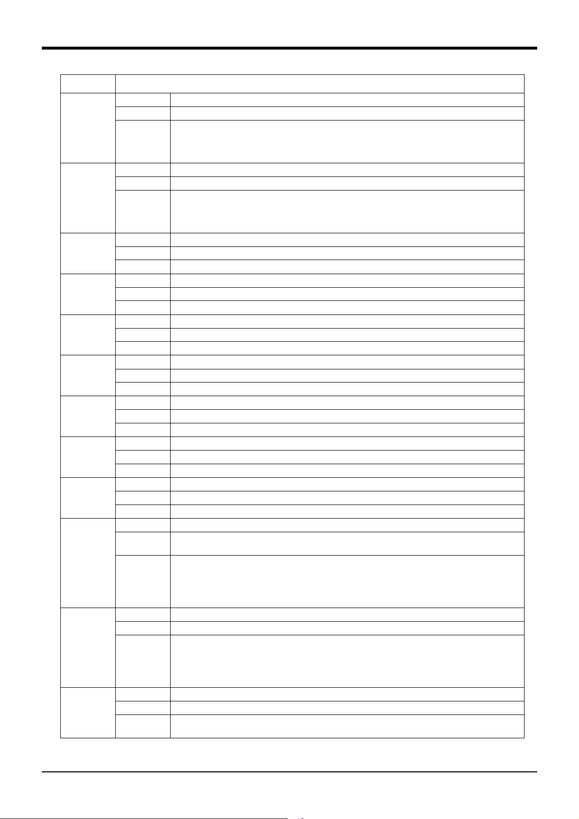
*CR751-D or CR751-Q controller
CAUTION
PE terminal
Grounding screw
Controller
ACIN connector
AC200V AC200V
Primary
Secondary
PE terminal
Grounding screw
123 123
ACIN connector
ACIN connector
Note 2)
Note 1) Crimping swage is recommended for connecting the attachment ACIN connector (soldering is also possible)
Recommendation compression tools: 234171-1(Tyco Electronics)
Note 2) The earth leakage breaker is the customer preparation. Always use the cover below.
Recommendation: For single primary power supply .........NV30FAU-2P-10A-AC100-240V-30mA, (Cover: TCS-05FA2)
For three primary power supply .......... NV30FAU-3P-10A-AC100-240V-30mA, (Cover: TCS-05FA3)
Note 3) If necessary, as shown in the figure, connects the noise filter between ACIN terminal blocks and primary power supply.
(Recommended noise filter: SUP-EL20-ER6 *OKAYA ELECTRIC INDUSTRIES)
Controller
<4> LINE/LOAD
<3> LINE/LOAD
<1> LINE/LOAD
<2> LINE/LOAD
Noise filter
Label
ACIN connector or
power cable
(Attachment)
Note 1)
For three phaseFor single phase
Three phase Single phase
Earth leak
-
age breaker
(NV)
Note 3)
* The controller is an
example.
Notes of the basic component are shown.
Please install the earth leakage breaker in the primary side supply power supply
of the controller of CR751-D or CR751-Q because of leakage protection.
1) Please prepare the following: Leakage current breaker (with the terminal cover), cable for connecting the
primary power supply (AWG #14 (2mm
2
or above).
(3.5mm
The secondary power cable (with the ACIN connector) for single phase or three phase power is supplied with
the product to match the specifications. When you build a cable suitable for your environment using the ACIN
connector and the ACIN terminal supplied, prepare a secondary power cable (AWG #14 (2mm
2) Confirm that the primary power matches the specifications.
3) Confirm that the primary power is OFF and that the earth leakage breaker power switch is OFF.
4) Connect the secondary power cable.
a) When using the supplied power cable with the ACIN connector
Refer to the figure above and connect the cable from the secondary side of the earth leakage breaker.
b) When building a power cable using the ACIN connector and the ACIN terminals supplied
Connect the ACIN terminals with the secondary power cable (prepared by customers), and insert the ACIN
terminals to the ACIN connector pins with the following numbers. Crimping caulking is recommended to
connect the ACIN terminals.
For single phase: 1 and 3
For three phase: 1, 2, and 3
Refer to the figure above and connect the cable from the secondary side of the earth leakage breaker.
5) Connect this ACIN connector to the ACIN connector on the front of the controller.
6) Connect the grounding cable to the PE terminal. (M4 screw)
7) Connect the primary power cable to the primary side terminal of the earth leakage breaker.
2
or above), cables to ground the primary power supply (AWG #12
2
) or above).
Revision history
Date of print Specifications No. Details of revisions
2012-02-13 BFP-A8871 ・ First print
2012-06-11 BFP-A8871-A ・ Error H096n was corrected (measures in RH-20FH).
・ The cause and measures of error H017m were corrected.
2012-06-18 BFP-A8871-B ・ The measures of H096n was corrected (measures in RH-20FH)
2012-09-03 BFP-A8871-C ・ The measures of H0094 was corrected.
・ Error L4939 and L2050 were added.
2012-10-15 BFP-A8871-D ・ The message and cause of the error L3110 and L3120 were corrected.
2012-11-20 BFP-A8871-E ・ Error C043n was added.
・ The statement about trademark registration was added.
・ The issue item of the “2.1 Appendix” was added.
2013-07-17 BFP-A8871-F ・ Error C1940 was added.
2013-09-10 BFP-A8871-G ・ The measures of H096n and C133n were added.
2013-12-25 BFP-A8871-H ・ Following errors were added.
2014-03-31 BFP-A8871-J ・ Following errors were added.
2014-08-06 BFP-A8871-K • The cover and corporate logo mark of this manual was changed
2014-08-20 BFP-A8871-M ・ The description was modified to measures.
2014-12-15 BFP-A8871-N ・ The measures were modified.
2015-02-10 BFP-A8871-P ・ The causes and measures of error H0083 were modified.
・ The measures of H8800 was corrected.
・ The cause and measures of following errors were corrected.
H0050, H0060, H0080, H0083, H0087, H0088, H0090, H0093, H0094, H0141, H104n, H107n,
L182n, C1920
・ The causes and measures of H112n was modified.
・ ”The T/B does not display anything.” was added to “Appendix 3: Troubles and measures”
L1864, H2760, H2770, H2780, L3110, L3770, L3986, L3987, H3988, H7650, H7651, H7652,
H766n, H8920, C8921
・ Following errors were deleted.
C7410, C7420, C7430, C7440
・ The causes were modified.
H216n, H217n
・ The causes and measures were modified.
H0083, H0087, L4110
・ The digit of the end of following error number was changed into the axis number (n).
C753n, C754n
・ The fuse replacement method of an air hand and brake was modified.
L2041, L2042, L2610, L2611, L2612, L2613, L2614, L2615, L2621, L2622
・ The description was added to measures.
H1090, H109n
・ The causes and measures were modified.
H0044
H0130, H8800
・ The causes and measures were modified.
H0088, H1090/109n
・ Correction of errors.
L5150, H112n, C132n, L182n
・ The causes and measures were modified.
H0742, H1682
・ The corporate logo mark of illustrations in this manual was changed.
・ The error message of error H0141 was corrected.
Date of print Specifications No. Details of revisions
2015-10-29 BFP-A8871-R ・ Converter circuit board is added to the table of applicable fuses in ”Fig. 2-1: Pneumatic
2015-12-14 BFP-A8871-S ・ Error L8680 was added.
2016-03-07 BFP-A8871-T ・ The causes and measures of error H1410 were corrected.
2016-09-09 BFP-A8871-U ・ The measure of error H0099 and L3100 were revised.
hand’s power fuse exchange place”.
・ The causes and measures were added.
L2610, L2611
・ The measures were modified.
H0820/H082n, H093n, C1410
・ Following errors were added.
H0097, H0098, H0210, H0211, H0212, H0213, H0220, H0230, H0240, H220m, H221n, H222m,
H2240, C2250, H2260, H2300, H2310, H2320, H2340, H2370, H238n, H6640, C7081, L7378,
L2580, L3141, L3142, L8623, L4941, L2430, H0690, H0770, H081n, H093n, H113n, H148n,
L3100
・ The explanations of CR760 controller was added.
・ Error H1450 and L4341 were added.
・ The cause of error L4190 was revised.
・ Error H0009 was revised.
・ Error H264n and H265n were added.

■ Introduction
・ No part of this manual may be reproduced by any means or in any form, without prior consent from
Mitsubishi.
・ The contents of this manual are subject to change without notice.
・ An effort has been made to make full descriptions in this manual. However, if any discrepancies or
unclear points are found, please contact your service provider.
・ The information contained in this document has been written to be accurate as much as possible.
Please interpret that items not described in this document "cannot be performed." or "alarm
may occur".
Please contact your service provider if you find any doubtful, wrong or skipped point.
・ This specifications is original.
・ The ETHERNET is a registered trademark of the Xerox Corp.
・ All other company names and production names in this document are the trademarks or registered
trademarks of their respective owners.
Copyright(C) 2012-2016 MITSUBISHI ELECTRIC CORPORATION
Notice
*ONLY QUALIFIED SERVICE PERSONNEL MAY INSTALL OR SERVICE THE ROBOT SYSTEM.
*ANY PERSON WHO PROGRAM, TEACHES, OPERATE, MAINTENANCE OR REPAIRS THE ROBOT
SYSTEM IS TRAINED AND DEMONSTRATES COMPETENCE TO SAFELY PERFORM THE
ASSIGNED TASK.
*ENSURE COMPLIANCE WITH ALL LOCAL AND NATIONAL SAFETY AND ELECTRICAL CODES
FOR THE INSTALLATION AND OPERATION OF THE ROBOT SYSTEM.
Thank you for purchasing the Mitsubishi industrial robot. This instruction manual describes the causes and
measures for errors that may occur while using the robot.
If an error should occur, refer to this manual and take appropriate measures.
Apply to both the CR750-Q/CR751-Q/CR760-Q series controller corresponding to iQ Platform, and the
CR750-D/CR751-D/CR760-D series controller of standalone. Especially the function added individually
is indicated to be "CR750-Q" and "CR750-D".

Contents
Page
1 Error list .............................................................................................................................................................................................. 1-1
(1) Error No. .......................................................................................................................................................................... 1-1
(2) If the display of the operation panel goes out ................................................................................................ 1-1
(3) Cause and measures against the error .............................................................................................................. 1-1
2 Appendix .......................................................................................................................................................................... Appendix-58
2.1 Place where fuse replacement is required ................................................................................................ Appendix-58
2.1.1 Place where a hand fuse or brake fuse replacement is required. ............................................ Appendix-58
(1) CR750/CR751 controller ...................................................................................................................... Appendix-58
(2) CR760 controller ...................................................................................................................................... Appendix-59
2.1.2 Place where fuse (F8) replacement is required. .............................................................................. Appendix-60
2.2 Fan installation place of robot controller (drive unit). .......................................................................... Appendix-61
2.3 Troubles and measures ...................................................................................................................................... Appendix-62
2.4 Errors involving change in specification ..................................................................................................... Appendix-65
2.5 Force sense interface unit errors ................................................................................................................. Appendix-66
i
1Error list
[Note] ・ The meaning of the error Nos. in Table 1-1 are shown below.
□ 0000
*
・An error marked with a * reset by turning the power OFF and ON.
Take the measures given.
・ The error type is indicated with a 4-digit number.
・ Three types of error classes are indicated.
H: High level error.................The servo turns OFF.
L: Low level error ..................The operation will stop.
C: Warning ................................The operation will continue.
・ The axis No. may be indicated at the last digit of the error No.
Example) H0931 No. 1 axis motor overcurrent.
1 Error list
(1) Error No.
When an error occurs, a 5-digit error No. (example: "C0010") will appear at the STATUS NUMBER display on the
operation panel at the front of the controller, and the [RESET] switch lamp will light.
The four-digit error number (number except the one character of the head.) is displayed on LCD of T/B.
Example: In the case of C0010, display the display and the error message for "0010."
The message, cause and measures to be taken are displayed in Table 1-1 for the error Nos. that may appear.
Also, a detailed message will be displayed on the Error History screen of the T/B, depending on the error No. of
the error occurred. Check by displaying the Error History screen after resetting the error.
If the error recurs even after the measures in the table are taken, contact your service provider.
(2) If the display of the operation panel goes out
If the operation panel display of the front of the controller (drive unit) goes out, turn off the power supply once,
and turn on again.
If the error occurs, please take measures with reference to "Table 1-1: Error list" And, please confirm the error
history, even if no error occurred, and take necessary measures. Refer to the separate manual, "Instruction
Manual/Detailed Explanation of Functions and Operations" for the confirmation method of the error history. If
the operation panel display goes out again after measures, please contact to your service provider.
(3) Cause and measures against the error
The details, cause and measures of the error number occurrence are shown in Table 1-1.
Note) The contents of the error caused with option products are written in the instruction manual of the option.
Refer to each instruction manual.
Table 1-1 : Error list
Error No. Error cause and measures
H0001 Error message Fail safe error (SRVOFF)
Cause The system may be abnormal.
Measures Turn the power OFF and ON once. If it comes back, contact to your service provider.
H0002 Error message Fail safe error (STOP)
Cause The system may be abnormal.
H0003 Error message The system is abnormal.
H0004 * Error message CPU Watch dog error
Measures Turn the power OFF and ON once. If it comes back, contact to your service provider.
Cause The problem of the system is the cause.
Measures If it comes back, contact to your service provider.
Cause CPU was not normally treatable
Measures It is necessary to change some parts when not improvement. If it comes back, contact to your service
provider.
1-1
Error no. H0001
Error No. Error cause and measures
H0009 * One of the errors below is detected.
Please take measures corresponding to an error message.
Error message Version UP (ALL)
Cause Message at version up.
Measures Turn the power OFF and ON once.
Error message Version UP (MAIN)
Cause Version UP (MAIN)
Measures Turn the power OFF,ROTSW=0 and power ON once
Error message Version UP (SERVO)
Cause Version UP (SERVO)
Measures Turn the power OFF,ROTSW=0 and power ON once
Error message The servo s/w was written
Cause The servo s/w was written
Measures Turn the power OFF and power ON once
C0010 Error message Illegal Version (file)
Cause The version is inconsistent.
Measures The file has been automatically initialized. The program is being deleted.
C0011 Error message Illeagal Version (system data)
Cause The version is inconsistent.
Measures The file has been automatically initialized. Turn the power OFF and ON once.
C0012 Error message Initialize (error log)
Cause The error log has been initialized because of version mismatch or the error log file is abnormal.
Measures Reset the alarm, and continue the operation.
C0013 * Error message Illeagal file
Cause Data including programs may have been damaged.
Measures Contact your service provider as the initialization operation is required.
H0014 * Error message System error (illegal MECHA)
Cause A character string cannot exceed 14 characters.
Measures Re-input the correct name.
H0015 * Error message Illeagal Version (file)
Cause Illeagal Version (file)
Measures Contact the maker.
L0016 * Error message Turn the power OFF and ON once
Cause The time from turning the power OFF to turning the power ON again is too short.
Measures Give more time before turning the power ON again after turning the power OFF.
H0020 * Error message System Error (same name is Backup data.)
Cause The data of the system backup area is abnormal.
Measures Please consult your service provider.
H0021 * Error message System Error (Backup data is Count over.)
Cause The control region is overflowing.
Measures Please consult your service provider.
H0022 * Error message System Error (Backup data is no area.)
Cause The region is too small.
Measures Please consult your service provider.
L0030 Error message Hand error. LS release
Cause This is a user setting error.
Measures Reset the error after removing the cause.
1Error list
Error no. H0009 *
1-2
1Error list
Error No. Error cause and measures
L0031 Error message Air pressure error
Cause This is a user setting error.
Measures Reset the error after releasing the cause.
H0039 Error message Door Switch Signal line is faulty.
Cause The one point of contact in 2 points of contact of the door switch has broken. Or wiring is not the double
lines.
Measures Turn off the power supply.
Confirm whether there is any problem in wiring of the switch. And, please confirm whether it is wiring of the
double line. Refer to the "Examples of safety measures" given in separate "Standard Specifications
Manual" for door switch wiring.
Turn on the power supply again after checking.
H0040 Error message Door Switch Signal is Input
Cause The door switch is open.
Measures Confirm whether the door switch input signal is connected correctly. And close the door connected to the
input signal of door switch.
H0041 * One of the errors below is detected.
Please take measures corresponding to an error message.
Error message Comm. error (Remote I/O #1).
Cause Communication line is illegal.
Measures Checks the remote I/O cable connection between the CPU and the drive unit in the CR7xx-Q controller.
Checks the communication cable is grounded correctly or connected correctly.
Error message The CRC error of remote I/O channel 1 occurs
Cause An error was found in the communication line for remote I/O channel 1.
Measures Checks the remote I/O cable connection between the CPU and the drive unit in the CR7xx-Q controller.
H0042 * Error message Comm. error (Remote I/O #2).
Cause Communication line is illegal.
Measures Checks the remote I/O cable connection in the CR750-Q/CR751-Q controller.
H0044 Error message OP Mode key line is faulty.
Cause The state of doubled line is not matching (OP Mode key line)
The state of doubled line is not matching (Key switch interface)
Wiring might be connected to reserved pins of exclusive input/output signals connectors.
This error may occur when the mode key switch of the operation panel is turned slowly.
Measures Turn off the power and confirm whether wiring of the key switch interface is right. Wiring needs to be dou
bled.
Check the wiring to the connectors of exclusive output signals is connected correctly.
Turn the power OFF and ON once. If it comes back, contact to your service provider.
H0045 Error message Faulty Line (T/B Enable Switch).
Cause The state of doubled line is not matching (T/B Enable Switch).
Measures Turn the power OFF and ON once. If it comes back, contact to your service provider.
H0046 Error message Faulty wiring (Enabling Device).
Cause The state of doubled wiring is not matching (Enabling Device).
Measures Turn off the power and confirm whether wiring of the switch is right. Wiring needs to be doubled. Refer to
the separate manual, "Standard Specifications Manual" for wiring of the door switch.
H0050 Error message EMG signal is input. (external)
Cause 1) The external emergency stop is being input.
If the emergency stop of T/B turns on, this error may occur simultaneously.
2) The fuse (4A fuse) installed at the bottom of the 24 V power supply circuit in the controller may have
blown out. For the fuse blowout, the emergency stop made by the customer may be the cause, or there
may be a ground fault or short circuit with the 24 V power supply in the wiring of a door switch, enabling
device, etc.
Measures 1) Release the external emergency stop signal.
2) Investigate and correct the ground fault or short circuit portion in the wiring made by the customer.
Then, replace the fuse inside the controller. Refer to Page 60, "Fig.2-3 : Fuse (F8) exchange place
(CR750/CR751 controller)" for details. (On details of the fuse, contact the manufacturer.)
-
1-3
Error no. L0031
Error No. Error cause and measures
H0051 Error message Wiring of the external emergency stop is abnormal.
Cause If the emergency stop of T/B turns on, this error may occur simultaneously.
Measures Turn OFF the power supply.
Confirm whether there is any problem in wiring of the external emergency stop switch. And, please confirm
whether it is wiring of the dual line. Refer to the “Examples of safety measures” given in separate
“Standard Specifications Manual” for external emergency stop switch wiring. Turn on the power supply
again after checking.
H0053 Error message EMG signal is input.(Add.Axis2)
Cause The external emergency stop to addition axis amplifier is inputting.
Measures Check the emergency stop of Additional Axis servo amp. Or the EM1 (forced outage) line of the addition
axis may be open. Please confirm connection. In addition, the External Emergency Stop 1 and 2 are sepa
rated. The "External Emergency Stop 1" is for I/F card, and the "External Emergency Stop 2" is for main
device of the amplifier
H0060 One of the errors below is detected.
Please take measures corresponding to an error message.
Error message EMG signal is input. (O.Panel)
Cause 1) The operation panel emergency stop is being input.
2) The fuse (4A fuse) installed at the bottom of the 24 V power supply circuit in the controller may have
blown out. For the fuse blowout, the emergency stop made by the customer may be the cause, or there
may be a ground fault or short circuit with the 24 V power supply in the wiring of a door switch, enabling
device, etc.
Measures 1) Cancel the operation panel emergency stop.
2) Investigate and correct the ground fault or short circuit portion in the wiring made by the customer.
Then, replace the fuse inside the controller. Refer to Page 60, "Fig.2-3 : Fuse (F8) exchange place
(CR750/CR751 controller)" for details. (On details of the fuse, contact the manufacturer.)
H0061 Error message EMG line is faulty.(0.Panel)
Cause The emergency stop line isn't stable.
Measures Confirm whether there is any problem in wiring of the external emergency stop switch. And, please confirm
whether it is wiring of the double line. Refer to the "Examples of safety measures" given in separate
"Standard Specifications Manual" for external emergency stop switch wiring. Turn on the power supply
again after checking.
H0070 Error message EMG signal is input. (T.Box)
Cause EMG signal is input. (T.Box) Or when using the UL specification, the brake release switch is turning ON.
Measures Cancel the T/B emergency stop. Check the emergency stop switch of teaching pendant.. Or when using
the UL specification, turn OFF the brake release switch.
If the alarm cannot be canceled, check the fuse of the safe unit (TZ348). If the fuse broke off, exchange
new fuse.
H0071 Error message EMG line is faulty.(T.Box)
Cause The emergency stop line isn't stable.
Measures Confirm whether there is any problem in wiring of the external emergency stop switch. And, please confirm
whether it is wiring of the double line. Refer to the "Examples of safety measures" given in separate
"Standard Specifications Manual" for external emergency stop switch wiring. Turn on the power supply
again after checking.
H0074 Error message Faulty line (T/B Enable/Disable).
Cause The state of doubled line is not matching (T/B Enable/Disable).
Measures Confirm whether T/B is connected correctly. If it comes back, contact to your service provider.
H0075 Error message TB communication error
Cause Communication between the RC and TB was cut off.
Measures If it comes back, contact your service provider.
1Error list
-
Error no. H0051
1-4
1Error list
Error No. Error cause and measures
H0083 * Error message Fuse is broken (hand input power)
Cause 1) The pneumatic hand's power fuse has broken. Possibly the power supply line of the hand input/output
signal short-circuited.
2) If any other error occurred simultaneously, the fuse (4 A fuse, model: LM40) installed at the bottom of
the 24 V power supply circuit in the controller may have blown out. For the fuse blowout, the emergency
stop made by the customer may be the cause, or there may be a ground fault or short circuit with the 24
V power supply in the wiring of a door switch, enabling device, etc.
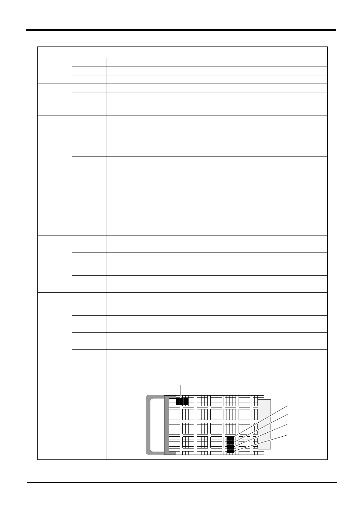
Measures 1) Confirm that the hand input/output cable is connected correctly. Exchange the fuse. Refer to the Page
58, "Fig.2-1 : Pneumatic hand’s power fuse and brake fuse exchange place (CR750/CR751 controller)"
for details.
If the error recurs after replacing the fuse, contact the manufacturer.
2) Investigate and correct the ground fault or short circuit portion in the wiring made by the customer.
Then, replace the fuse inside the controller. Refer to Page 60, "Fig.2-3 : Fuse (F8) exchange place
(CR750/CR751 controller)" for details. (On details of the fuse, contact the manufacturer.)
H0084 * Error message Fuse is broken (O/P)
Cause The operation panel's power fuse has broken.
Measures Exchange the fuse.
H0086 Error message Hand module overcurrent
Cause The motorized hand's motor or circuit board has broken.
Measures Exchange the motorized hand's motor or circuit board.
H0087 Error message Fuse is blown.(Brake)
Cause 1) A brake failure or a ground fault of brake cable may have caused the error.
2) The fuse (4A fuse) installed at the bottom of the 24 V power supply circuit in the controller may have
blown out. For the fuse blowout, the emergency stop made by the customer may be the cause, or there
may be a ground fault or short circuit with the 24 V power supply in the wiring of a door switch, enabling
device, etc.
Measures 1) There are two brake fuses. Replace both the fuses.
2) After the ground fault is removed from the wiring, replace the fuse (4 A fuse, model: LM40) for the 24 V
power supply in the controller. Refer to Page 60, "Fig.2-3 : Fuse (F8) exchange place (CR750/CR751
controller)" for details. (On details of the fuse, contact the manufacturer.)
H0088 Error message Service I/F fuse error
Cause 1) In SQ series, when the power supply of robot CPU is turned on, the drive unit has not started.
2) The fuse (4A fuse) installed at the bottom of the 24 V power supply circuit in the controller may have
blown out. For the fuse blowout, the emergency stop made by the customer may be the cause, or there
may be a ground fault or short circuit with the 24 V power supply in the wiring of a door switch, enabling
device, etc.
3) In CR7xx-Q controller, the power on timing may be incorrect.
Measures 1) The order which turns on the power supply should turn on the power supply of robot CPU, in the
condition that the drive unit is started previously.
2) Investigate and correct the ground fault or short circuit portion in the wiring made by the customer.
Then, replace the fuse inside the controller. Refer to Page 60, "Fig.2-3 : Fuse (F8) exchange place
(CR750/CR751 controller)" for details. (On details of the fuse, contact the manufacturer.)
3) In CR7xx-Q controller, turn on the switch of the drive unit, then of the robot CPU when turning the
power ON.
H0090 Error message DC24V fuse is blown.
Cause 1) DC24V fuse is blown.
2) The fuse (4A fuse) installed at the bottom of the 24 V power supply circuit in the controller may have
blown out. For the fuse blowout, the emergency stop made by the customer may be the cause, or there
may be a ground fault or short circuit with the 24 V power supply in the wiring of a door switch, enabling
device, etc.
Measures 1) Change fuse.
2) Investigate and correct the ground fault or short circuit portion in the wiring made by the customer.
Then, replace the fuse inside the controller. Refer to Page 60, "Fig.2-3 : Fuse (F8) exchange place
(CR750/CR751 controller)" for details. (On details of the fuse, contact the manufacturer.)
L0091 Error message Can't access the Special signal
Cause The dedicated output signal is assigned to the specified signal. This signal cannot be used in duplicate.
Measures Confirm whether the same dedicated output number is assigned to the separate dedicated output signal.
Change the output No., or change the dedicated output assignmen
t parameter.
1-5
Error no. H0083 *
Error No. Error cause and measures
H0093 Error message Safety relay fuse is blown.
Cause 1) Safety relay fuse is blown.
2) Investigate and correct the ground fault or short circuit portion in the wiring made by the customer.
Then, replace the fuse inside the controller. Refer to Page 60, "Fig.2-3 : Fuse (F8) exchange place
(CR750/CR751 controller)" for details. (On details of the fuse, contact the manufacturer.)
Measures Change fuse.
H0094 Error message The overcurrent in the T/B line.
Cause 1) The overcurrent in the T/B power supply line was detected.
2) The fuse (4A fuse) installed at the bottom of the 24 V power supply circuit in the controller may have
blown out. For the fuse blowout, the emergency stop made by the customer may be the cause, or there
may be a ground fault or short circuit with the 24 V power supply in the wiring of a door switch, enabling
device, etc.
Measures 1) Contact to the dealer.
2) Investigate and correct the ground fault or short circuit portion in the wiring made by the customer.
Then, replace the fuse inside the controller. Refer to Page 60, "Fig.2-3 : Fuse (F8) exchange place
(CR750/CR751 controller)" for details. (On details of the fuse, contact the manufacturer.)
H0095 Error message Brake release switch is turning on.
Cause Cannot execute while brake release switch is turning on.
Measures Please check the brake release switch and turn it off.
H0097 * Error message Abnormal MC status
Cause The duplex magnetic contactor status signal status is not consistent.
Measures The status of the duplex system for the magnetic contactor (MC) is not consistent. After turning OFF the
power, turn ON the power again to reset the error. If the same error recurs, contact the manufacturer.
H0098 * Error message Abnormal SR status
Cause The duplex safety relay status signal status is not consistent.
Measures The status of the duplex system for the safety relay (SR) is not consistent. After turning OFF the power,
turn ON the power again to reset the error. If the same error recurs, contact the manufacturer.
H0099 Error message Servo version is illegal **
Note) The correct version of servo software is shown in "**".
Cause Servo software with an old version is installed.
Measures Change to the correct version of servo software is necessary. Refer to separate "Instruction Manual/
Detailed Explanation of Functions and Operations" for details of upgrading the servo software.
H0100 * Error message Temperature in the Controller is too high
Cause The intake fan is not operating, or the fan filter is clogged.
Measures Check the operation of the intake fan, or clean or replace the fan filter if necessary.
Confirms that the environmental temperature is the specification range.
When it comes back, contact to the dealer.
L0101 Error message Temperature in the Controller is too high
Cause The intake fan is not operating, or the fan filter is clogged.
Measures Check the operation of the intake fan, or clean or replace the fan filter if necessary.
Confirms that the environmental temperature is the specification range.
When it comes back, contact to the dealer.
C0102 Error message Temperature in the Controller is too high
Cause The intake fan is not operating, or the fan filter is clogged.
Measures Check the operation of the intake fan, or clean or replace the fan filter if necessary.
Confirms that the environmental temperature is the specification range.
When it comes back, contact to the dealer.
C0120 * Error message Instantaneous power failure
Cause The power was OFF for 20msec or more
Measures Check the power supply connection and power supply state
H0130 * Error message The initialization connection error of system remote I/O.
Cause Communication line of System Remote I/O is illegal
Measures Confirm whether the communication cable is grounded correctly or connection correctly.
In CR7xx-Q controller, turn on the switch of the drive unit, then of the robot CPU when turning the power
ON.
1Error list
Error no. H0093
1-6
1Error list
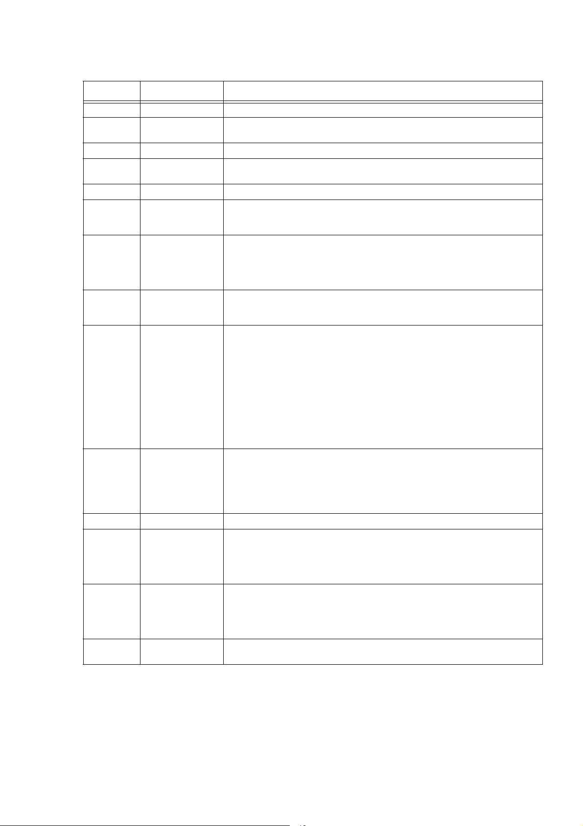
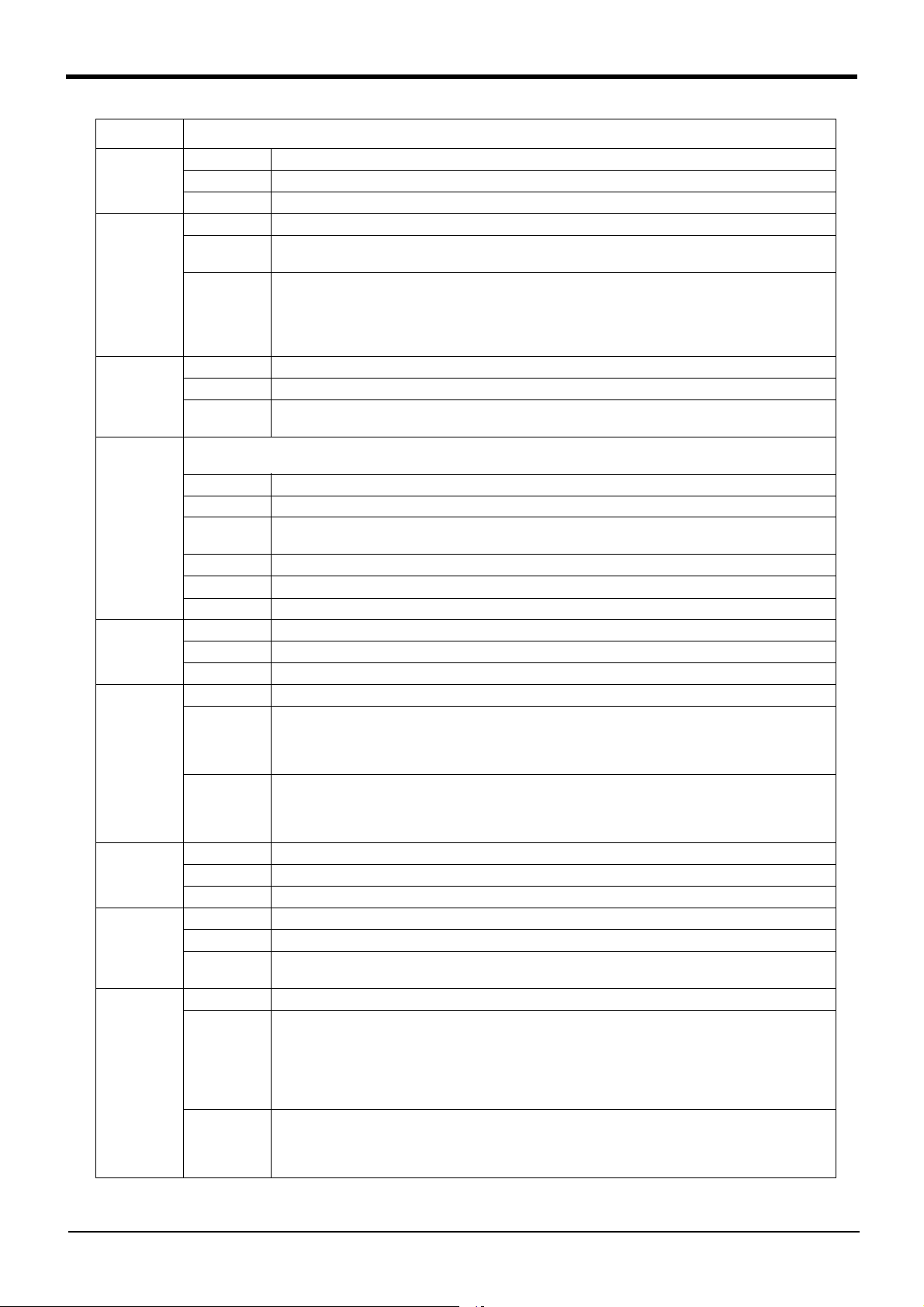
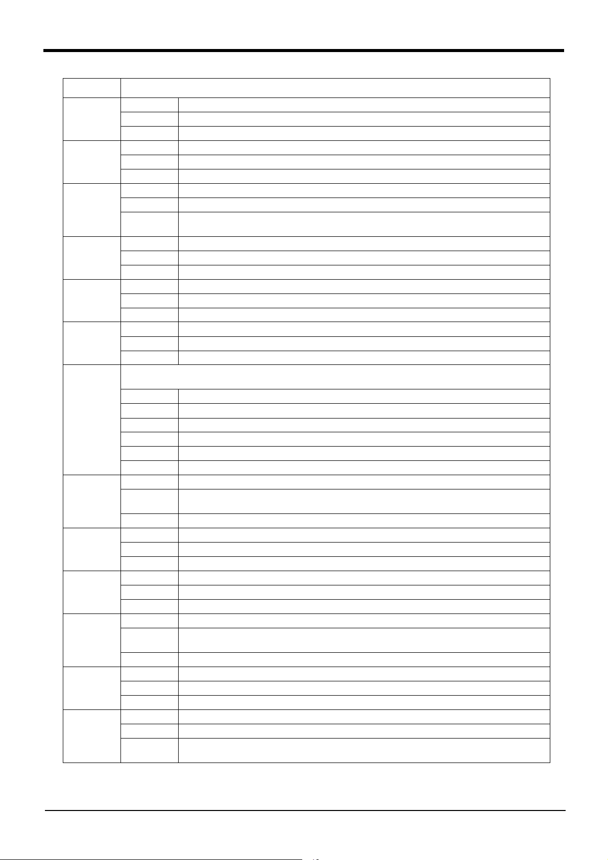
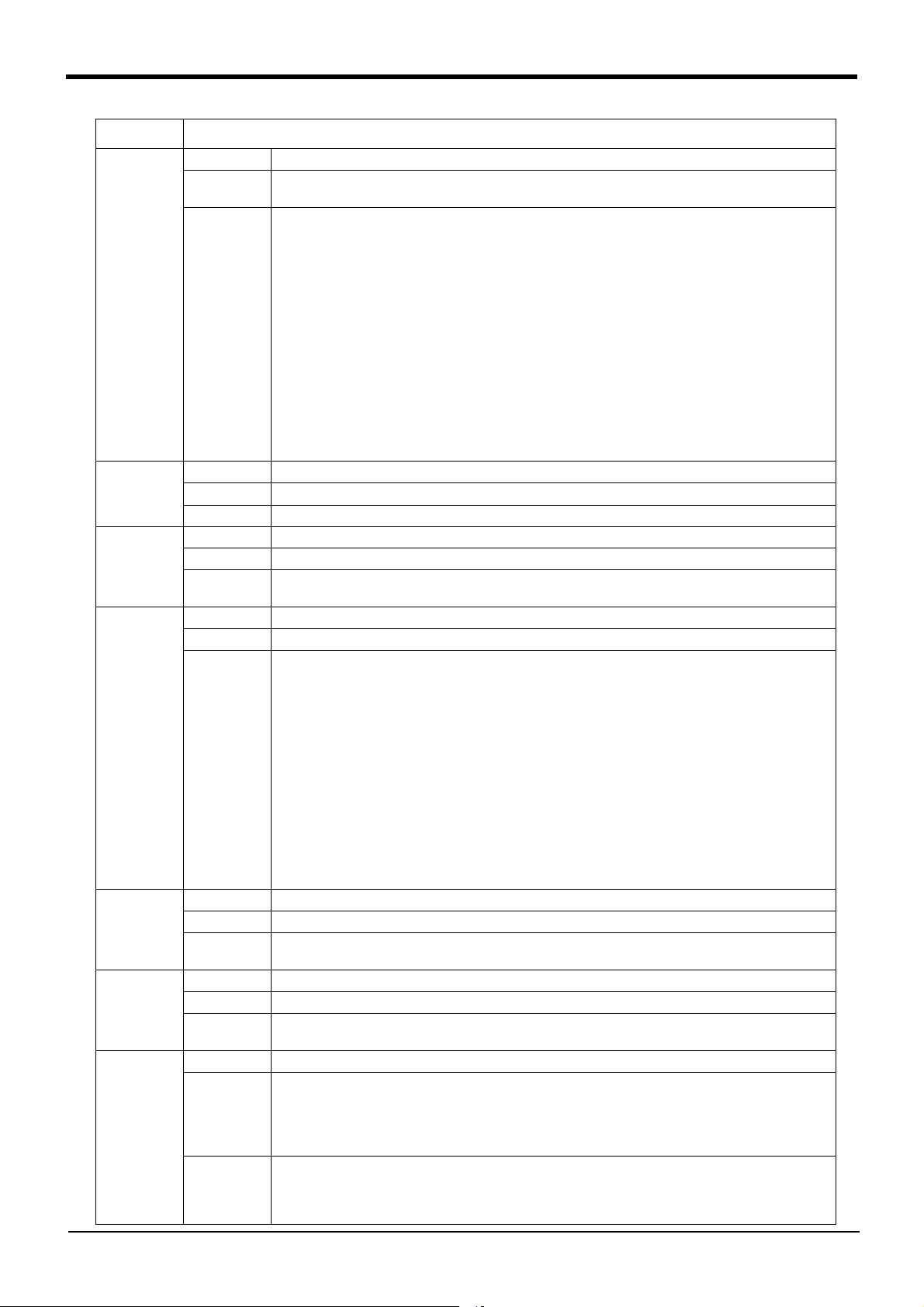
予備ヒ ューズ
ヒューズF1
ヒューズ F2
ヒューズ F3
ヒューズ F4
Fuse
Fuse F1
Fuse F2
Fuse F3
Fuse F4
Error No. Error cause and measures
H0131 * Error message Plural Ope-panel are installed.
Cause One operation panel can be installed.
Measures Install only one operation panel.
H0140 Error message Fuse is blown.(Safety unit)
Cause Fuse is blown.(Safety unit)
If external emergency stop is turning ON, this error occurs.
Measures Cancels the external emergency stop. When it comes back, contact to the dealer.
H0141 Error message Wiring error of CNUSR connector.
Cause 1) Wiring error of CNUSR connector.
Measures 1) Please confirm the wiring for CNUSR.
C0150 Error message Undefined robot serial number
Cause Undefined robot serial number
Measures Input the robot serial number Refer to separate manual: "Controller setup, basic operation, and mainte
H016m (m=1 ~ 3)
H017m (m=1 ~ 2)
H018m (m=1 ~ 2)
Error message Cannot use PIO I/F and Unit
Cause The I/O Channel number of PIO interface and PIO unit overlaps.
Measures Select either of Parallel I/O interface or Parallel I/O unit.
Error message Parallel I/O interface H/W error.
Cause The parallel-input/output card broke or the external power source for the parallel input/outputs was cut
Measures If it comes back, exchange the Parallel I/O interface card.
Error message Fuse is blown.(PIO) (Slot m-Fn)
Cause Fuse is blown.(Parallel I/O interface)
Measures Change fuse (Parallel I/O interface)
Details The electric fuse Fn (n= 1-4) of the parallel input output interface installed to the option slot m (m= 1-2) is
2) The fuse (4A fuse) installed at the bottom of the 24 V power supply circuit in the controller may have
blown out. For the fuse blowout, the emergency stop made by the customer may be the cause, or there
may be a ground fault or short circuit with the 24 V power supply in the wiring of a door switch, enabling
device, etc.
・ When using the internal power supply, the following terminals has not connected.
CR750 controller: between 1-2, 5-6 of CNUSR11/12.
CR751 controller: between 1-26, 6-31, 3-28, 8-33 of CNUSR1.
・ When using the external power supply, the external power supply is not supplied.
・ The electrical wire connected to the following terminal is earth fault.
CR750 controller: terminal 1 of CNUSR11/12.
CR751 controller: terminal 1, 6 of CNUSR1.
・ The 24V power supply is supplied to the following terminal.
CR750 controller: between 2-3 of CNUSR11/12.
CR751 controller: between 26-2 or 31-7 of CNUSR1.
When it comes back, contact to the dealer.
2) Investigate and correct the ground fault or short circuit portion in the wiring made by the customer.
Then, replace the fuse inside the controller. Refer to Page 60, "Fig.2-3 : Fuse (F8) exchange place
(CR750/CR751 controller)" for details. (On details of the fuse, contact the manufacturer.)
nance" for the setting method.
off.
open.
Removes the cause by which the fuse open and replaces the fuse.
-
1-7
Error no. H0131 *
Error No. Error cause and measures
H0210 * Error message Power supply fault (5V)
Cause The power supply output voltage is out of the specified range.
Measures The output voltage of the 5V power supply is the specified value or higher/lower. After turning OFF the
H0211 * Error message Power supply fault (3.3V)
Cause The power supply output voltage is out of the specified range.
Measures The output voltage of the 3.3V power supply is the specified value or higher/lower. After turning OFF the
H0212 * Error message Power supply fault (2.5V)
Cause The power supply output voltage is out of the specified range.
Measures The output voltage of the 2.5V power supply is the specified value or higher/lower. After turning OFF the
H0213 * Error message Power supply fault (1.3V)
Cause The power supply output voltage is out of the specified range.
Measures The output voltage of the 1.3V power supply is the specified value or higher/lower. After turning OFF the
H0220 * Error message Memory fault (main CPU)
Cause A memory fault is detected.
Measures A fault (inconsistent data between writing/reading, broken retention data) is detected for the memory
H0230 * Error message Parameter error (xxxxx)
Cause The parameter setting is illegal.
Measures The parameter setting is not correct. Check the parameter setting shown in the "(xxxxx)" part of the error
H0240 * Error message Inconsistent safety function setting
Cause The enable/disable setting of the safety function is not consistent.
Measures Inconsistency is detected in the enable/disable setting check of the safety monitoring function. After turn
C043n
(n indicates the
axis number (1
to 8).)
C049n * (n indicates the fan num ber (1 to 8).)
H050n * (n indicates the axis num ber (1 to 8).)
H0510 * Error message The converter setting is illegal
H0520 * Error message Robot axis setting illegal
H053n *
(n indicates the
axis number (1
to 8).)
Error message Servo amplifier motor overheat
Cause The motor or encoder’s thermal protector activated.
Measures Reduce the speed and acceleration of the robot.
Error message Alarm of fan in the robot
Cause Fan in the robot might be out of order
-
Measures Please exchange the fan in the robot
Error message Servo axis setting error
Cause The setting of the axis number selection switch is illegal
-
Measures Confirm the setting of the axis selection switch
Cause The external emergency-stop input power was detected except external emergency-stop mode.
Measures Setting is wrong. When it comes back, contact to the dealer.
Cause The setting of the servo axis used by the mechanism is duplicated with another mechanism's axis.
Measures Correctly set.
Error message Servo sys. error (memory)
Cause The servo amplifier memory IC's check sum is illegal.
Measures Turn the power OFF and ON once. If it comes back, contact your service provider.
power, turn ON the power again to reset the error. If the same error recurs, contact the manufacturer.
power, turn ON the power again to reset the error. If the same error recurs, contact the manufacturer.
power, turn ON the power again to reset the error. If the same error recurs, contact the manufacturer.
power, turn ON the power again to reset the error. If the same error recurs, contact the manufacturer.
(DRAM) to which the main CPU has access. After turning OFF the power, turn ON the power again to reset
the error. If the same error recurs, contact the manufacturer.
message, and set an appropriate value.
ing OFF the power, turn ON the power again to reset the error. Then, check the enable/disable setting of
the safety monitoring function.
When the applicable robot is not compatible with the safety monitoring function, disable all the settings of
the safety monitoring function.
1Error list
-
Error no. H0210 *
1-8
1Error list
Error No. Error cause and measures
H054n *
(n indicates the
axis number (1
to 8).)
H055n *
(n indicates the
axis number (1
to 8).)
H056n *
(n indicates the
axis number (1
to 8).)
H057n *
(n indicates the
axis number (1
to 8).)
H058n *
(n indicates the
axis number (1
to 8).)
H059n *
(n indicates the
axis number (1
to 8).)
H060n *
(n indicates the
axis number (1
to 8).)
H061n *
(n indicates the
axis number (1
to 8).)
H062n *
(n indicates the
axis number (1
to 8).)
H063n *
(n indicates the
axis number (1
to 8).)
H064n *
(n indicates the
axis number (1
to 8).)
H065n *
(n indicates the
axis number (1
to 8).)
Error message Servo sys. error (over run)
Cause The servo amplifier software data process did not end within the specified time.
Measures Turn the power OFF and ON once. If it comes back, contact your service provider.
Error message Servo sys. error (mag. pole pos)
Cause An error was detected in the magnetic pole position detection signal of the detector.
Measures Turn the power OFF and ON once. If it comes back, contact your service provider.
Error message Servo sys. error (A/D)
Cause An error was found in the servo amplifier's A/D converter during initialization.
Measures Turn the power OFF and ON once. If it comes back, contact your service provider.
Error message Encoder error (EEPROM)
Cause An error was detected in EEPROM data of the serial pulse encoder.
Measures Turn the power OFF and ON once. Also, carefully check whether there is no deviation in the operating
position of the robot. If it is deviated, set the origin position (OP) again. For more information about the
operating procedure, refer to the separate volume, "Instruction Manual/Robot Arm Setup to Maintenance."
If it comes back, contact your service provider.
Error message Encoder error (LED)
Cause The LED of the serial pulse encoder has been deteriorated.
Measures Turn the power OFF and ON once. If it comes back, contact your service provider.
Error message Encoder error (position data)
Cause An error was detected in the position data within a single rotation of the encoder.
Measures Turn the power OFF and ON once. Also, carefully check whether there is no deviation in the operating
position of the robot. If it is deviated, set the origin position (OP) again. For more information about the
operating procedure, refer to the separate volume, "Instruction Manual/Robot Arm Setup to Maintenance."
If it comes back, contact your service provider.
Error message Encoder no-signal detection 1
Cause An error was detected in the operating input of the detector mounted on the edge of the motor.
Measures Turn the power OFF and ON once. Also, carefully check whether there is no deviation in the operating
position of the robot. If it is deviated, set the origin position (OP) again. For more information about the
operating procedure, refer to the separate volume, "Instruction Manual/Robot Arm Setup to Maintenance."
If it comes back, contact your service provider.
Error message Encoder no-signal detection 2
Cause An error was detected in the operating input of the detector mounted on the edge of the machine.
Measures Turn the power OFF and ON once. Also, carefully check whether there is no deviation in the operating
position of the robot. If it is deviated, set the origin position (OP) again. For more information about the
operating procedure, refer to the separate volume, "Instruction Manual/Robot Arm Setup to Maintenance."
If it comes back, contact your service provider.
Error message Servo amplifier LSI error
Cause An operation error was detected in the LSI of the servo amplifier.
Measures Turn the power OFF and ON once. If it comes back, contact your service provider.
Error message Unused axis servo error
Cause A power module error occurred in an axis which not use the movement control.
Measures Turn the power OFF and ON once. If it comes back, contact your service provider.
Error message System error (ABS CPU)
Cause An error in the CPU of the absolute position linear scale was detected.
Measures Turn the power OFF and ON once. Also, carefully check whether there is no deviation in the operating
position of the robot. If it is deviated, set the origin position (OP) again. For more information about the
operating procedure, refer to the separate volume, "Instruction Manual/Robot Arm Setup to Maintenance."
If it comes back, contact your service provider.
Error message Absolute position error
Cause An error was detected in the absolute position detection circuit within the absolute position linear scale.
Measures Turn the power OFF and ON once. Also, carefully check whether there is no deviation in the operating
position of the robot. If it is deviated, set the origin position (OP) again. For more information about the
operating procedure, refer to the separate volume, "Instruction Manual/Robot Arm Setup to Maintenance."
If it comes back, contact your service provider.
1-9
Error no. H054n * (n indicates the axis number (1 to 8).)
Error No. Error cause and measures
H066n *
(n indicates the
axis number (1
to 8).)
H067n *
(n indicates the
axis number (1
to 8).)
H068n *
(n indicates the
axis number (1
to 8).)
H0690 * Error message Regeneration circuit error
H0700 * Error message P.S. external contactor fusing
H0710 * Error message Servo amp. relay error.
H0711 * Error message Power supply relay error
H0720 * Error message Power supply watch dog
H0730 * Error message Power supply rush relay fusing
H0740 * Error message Power supply main circuit error
H0742 Error message Power supply main circuit error
H0743 * Error message Power supply main circuit error3.
Error message Incremental position error
Cause An error was detected in the relative position detection circuit within the absolute position linear scale.
Measures Turn the power OFF and ON once. Also, carefully check whether there is no deviation in the operating
position of the robot. If it is deviated, set the origin position (OP) again. For more information about the
operating procedure, refer to the separate volume, "Instruction Manual/Robot Arm Setup to Maintenance."
If it comes back, contact your service provider.
Error message Encoder CPU error
Cause An error was detected in the CPU of the position detector.
Measures Turn the power OFF and ON once. Also, carefully check whether there is no deviation in the operating
position of the robot. If it is deviated, set the origin position (OP) again. For more information about the
operating procedure, refer to the separate volume, "Instruction Manual/Robot Arm Setup to Maintenance."
If it comes back, contact your service provider.
Error message Encoder LED error
Cause Deterioration of the position detector's LED was detected.
Measures Turn the power OFF and ON once. If it comes back, contact your service provider.
Cause A regenerative transistor or resistor error was detected
Measures Turn the power OFF and ON once. If it comes back, contact your service provider.
Cause The contactor was turned ON even though READY is OFF.
Measures Turn the power OFF and ON once. If it comes back, contact your service provider.
Cause The relay on servo cpu card did not turn ON.
Measures Turn the power OFF and ON once. If it comes back, contact your service provider.
Cause The discharge relay on converter card did not turn ON
Measures Turn the power OFF and ON once
Cause The converter software process did not end within the specified time.
Measures Turn the power OFF and ON once. If it comes back, contact your service provider.
Cause The rush resistance short-circuit relay did not turn OFF.
Measures Turn the power OFF and ON once. If it comes back, contact your service provider.
Cause The charge operation of the main circuit capacitor is not normal.
Connection of the external emergency stop has the mistake.
Measures Turn the power OFF and ON once.
Confirm that the power supply voltage is in the specification value and the connection of the external
emergency stop is correct.
If it comes back, confirm the time of occurrence of this error being "servo ON/OFF", or being "power sup
ply OFF/ON", and contact your service provider
Cause A main circuit voltage has decreased because of a failure of the Safety relay on a converter card.
Measures Turn the power OFF and ON once.
Confirm whether there is any problem in wiring of the external emergency stop switch.
Refer to the "Examples of safety measures" given in separate "Standard Specifications Manual" for exter
nal emergency stop switch wiring.
If it comes back, contact to your service provider.
Cause A main circuit voltage has decreased because of contactor fail.
Measures Turns off the power once and turns on on the power supply again. Confirm power supply voltage and the
connection of the external emergency stop. When it comes back, contact to the dealer.
1Error list
-
-
Error no. H066n * (n indicates the axis number (1 to 8).)
1-10
1Error list
Error No. Error cause and measures
H0750 * Error message Power supply memory error
Cause An error in the memory circuit of converter or AD converter was detected.
Measures Turn the power OFF and ON once. If it comes back, contact your service provider.
H0760 * Error message Power supply error
Cause An error was detected in the data comm. with the power supply
Measures Turn the power OFF and ON once
H0770 * Error message Power supply process error
Cause An error occurred in the process cycle of power supply
Measures Turn the power OFF and ON once. Check that there is not a source of noise. If it comes back, contact your
service provider.
H078n *
(n indicates the
axis number (1
to 8).)
H079n *
(n indicates the
axis number (1
to 8).)
H080n *
(n indicates the
axis number (1
to 8).)
H081n *
(n indicates the
axis number (1
to 8).)
H0820 *
H082n *
(n indicates the
axis number (1
to 8).)
H083n *
(n indicates the
axis number (1
to 8).)
H0840 * Error message Instantaneous power failure (SRV)
H0850 * Error message Power supply voltage incorrect
H0860 Error message Power supply overvoltage
H087n *
(n indicates the
axis number (1
to 8).)
Error message Servo amplifier watch dog
Cause The servo amplifier software process is not operating correctly.
Measures Turn the power OFF and ON once. If it comes back, contact your service provider.
Error message Servo amplifier board error
Cause An error was detected in the servo amplifier's PCB.
Measures Turn the power OFF and ON once. If it comes back, contact your service provider.
Error message Servo amplifier clock error
Cause An error was detected in the servo amplifier's clock.
Measures Turn the power OFF and ON once. If it comes back, contact your service provider.
One of the errors below is detected.
Please take measures corresponding to an error message.
Error message Servo amplifier under voltage
Cause The PN bus voltage dropped to 200V or less. Momentary power failure may have occurred.
Measures Check the primary voltage.
Error message Voltage error at accel/decel
Cause A motor control error was detected due to an input voltage drop
Measures Turn the power OFF and ON once. Check the primary voltage.
Error message Motor ground fault
Cause A motor ground fault was detected. A connection or conductance error may have occurred in the motor
cable.
Measures Turn the power OFF and ON once. Check connection and continuity of motor cable.
Error message Servo amplifier overvoltage
Cause The PN bus voltage rose to 400V or more.
Measures Check the primary power supply voltage. Turn the power OFF and ON once.
Cause A power shutdown status of 50 msec or longer has occurred.
Measures Check the power voltage. Turn the power OFF and ON once.
Cause The input power (L1, L2, L3) has an open phase, the voltage is not within the specifications, or the 100V/
200V specifications changeover setting is incorrect.
Measures Check the power connection, power state or the setting.
Cause The voltage across the converter's L+ and L- exceeded 410V.
Measures Check the power supply connection and power supply state.
Error message Encoder thermal error
Cause The built-in thermal protector of the serial pulse encoder has been activated.
Measures Turn the controller power OFF, wait a while, and then turn ON again. If it comes back, contact your service
provider.
1-11
Error no. H0750 *

Error No. Error cause and measures
H0880 *
H088n *
(n indicates the
axis number (1
to 8).)
H089n
(n indicates the
axis number (1
to 8).)
H090n *
(n indicates the
axis number (1
to 8).)
H091n *
(n indicates the
axis number (1
to 8).)
H0920 *
H092n *
(n indicates the
axis number (1
to 8).)
H093n *
(n indicates the
axis number (1
to 8).)
H094n
(n indicates the
axis number (1
to 8).)
H095n
(n indicates the
axis number (1
to 8).)
Error message Power module overheat
Cause Overheating of the power module regenerative resistor was detected.
Measures Turn the controller power OFF, wait a while, and then turn ON again. If it comes back, contact your service
provider.
Error message Servo amplifier motor overheat
Cause The position detector's thermal protector activated.
Measures Turn the controller power OFF, wait a while, and then turn ON again. Decrease the acceleration/
deceleration time of the operation speed, for instance.
Refer to "Detailed explanation of command words"/"Accel (Accelerate)," "Ovrd (Override)" and "Spd
(Speed)," or "Detailed explanation of Robot Status Variable"/"M_SetAdl," "M_LdfAct" and "Functions set
with parameters"/"JADL (Optimum acceleration/deceleration adjustment rate)" of the Separate Volume,
"INSTRUCTION MANUAL/Detailed Explanation of Functions and Operations."
Error message Absolute position overspeed
Cause It moved 45 mm/sec or faster with the absolute position linear scale during initialization.
Measures Turn the power OFF and ON once. If it comes back, contact your service provider.
Error message Servo amplifier overspeed
Cause A speed exceeding the motor's tolerable speed was detected.
Measures Turn the power OFF and ON once. If it comes back, contact your service provider.
Error message Power module overcurrent
Cause A servo amplifier or power supply overcurrent was detected. An error was detected in the servo amplifier's
gate circuit. A connection or conductance error may have occurred in the motor cable .
Measures Confirms the connection of the machine cable and the locomotion-axis cable. If it comes back, contact
your service provider.
One of the errors below is detected.
Please take measures corresponding to an error message.
Error message Motor overcurrent
Cause An excessive current flowed to the motor, or the A/D converter output is abnormal. An abnormality may
have occurred in the connection of the motor's power line.
Measures Turn the power OFF and ON once. Confirms the connection of the machine cable and the locomotion-axis
cable etc. If it comes back, contact your service provider.
Error message Motor overcurrent (Grounding)
Cause The motor power cable is in contact with ground
Measures Turn the power OFF and ON once. Confirms the connection of the machine cable and the locomotion-axis
cable etc. If it comes back, contact your service provider.
Error message Overload (over weight 1)
Cause Operation tight for a motor (operation with high duty) was performed more than fixed time.
Measures Decrease the acceleration/deceleration time of the operation speed, for instance.
Refer to "Detailed explanation of command words"/"Accel (Accelerate)," "Ovrd (Override)" and "Spd
(Speed)," or "Detailed explanation of Robot Status Variable"/"M_SetAdl," "M_LdfAct" and "Functions set
with parameters"/"JADL (Optimum acceleration/deceleration adjustment rate)" of the Separate Volume,
"INSTRUCTION MANUAL/Detailed Explanation of Functions and Operations."
Confirms that conveyance conditions (hand mass, work-piece mass) are less than specification values.
When it comes back, contact to the dealer.
Error message Overload (over weight 2)
Cause The maximum output current continued for more than one second.
Measures Check the load weight and the robot pressing, etc.
Confirms that conveyance conditions (hand mass, work-piece mass) are less than specification values.
When it comes back, contact to the dealer.
1Error list
Error no. H0880 * H088n * (n indicates the axis number (1 to 8).)
1-12
1Error list
Error No. Error cause and measures
H096n
(n indicates the
axis number (1
to 8).)
H097n
(n indicates the
axis number (1
to 8).)
H098n
(n indicates the
axis number (1
to 8).)
H101n
(n indicates the
axis number (1
to 8).)
H102n
(n indicates the
axis number (1
to 8).)
H1030 * Error message Power supply over-regeneration
H104n *
(n indicates the
axis number (1
to 8).)
Error message Excessive error 1
Cause The position error exceeded at servo ON.
Moreover, this error may occur during the emergency-stop deceleration.
Measures ・ Check the load weight and press, etc.
Confirms the connection of the machine cable and the locomotion-axis cable etc.
If the surrounding temperature is low, or starting after stopping operation for an extended period of time,
perform running-in operation at low speed or use the warm-up operation mode.
・ When hand offset is long and acceleration-and-deceleration control is fixed or tracking is active in RH-
20FH series.
please reduce the acceleration and deceleration speeds (Accel command) and movement speed (Ovrd
command). Refer to separate "Instruction Manual/Detailed Explanation of Functions and Operations" for
details of each command.
(This error may occur during the emergency-stop deceleration.)
・ While operation is performed in the compliance mode of the joint coordinate system, if the Excessive error
1 (H096n) occurs, increase the set value of parameter CMPJCLL to suppress this error.
Refer to "Detailed explanation of command words"/"Cmp Jnt (Compliance Joint)" and "Movement
parameter"/"CMPJCLL (Current Limit Level for Cmp Jnt)" given in separate "INSTRUCTION MANUAL/
Detailed explanation of functions and operations".
(To use this function, the controller software version R4b/S4b or later is required.)
Error message Excessive error 2
Cause The position error exceeded at servo OFF.
Measures Check the moving robot arm by something power. When it comes back, contact to the dealer.
Error message Excessive error 3
Cause Abnormal motor power line connection.
Measures Check the connection of motor power line. When the excessive error 1 was detected, the current of the
motor is off.
Error message Collision detection
Cause A collision was detected.
Measures 1) If the robot has stopped by interference with peripheral equipment, move the arm to part from peripheral
equipment using jog operation. Depending on the level of collision, the collision detection error may occur
again. In that case, turn on the servo power again and do jog operation. If it still recurs, release the brake
and move the arm by hand.
2) If this error occurs without having collided, please adjust the collision detection level. If collision is
detected incorrectly during automatic operation, enlarge the setting value of the parameter (COLLVL)
corresponding to axis. If collision is detected incorrectly during jog operation, enlarge the setting value of
the parameter (COLLVLJG) corresponding to axis. However, since the detection level drops by enlarging
the set value, don't enlarge too much. And, the incorrect detection can be reduced when setup value of
parameter (HNDDATn、 WRKDATn) is correct.
3) If the speed excessive error has occurred at the same time, the torque alteration by rapid speed change
may be detected as a collision state. Remove other causes of the error and confirm movement again.
4) In case of operation under the environment of low temperature or after the long term stoppage, the col
lision detection error may occur by viscous transmutation of the grease used. In such a case, operate by
accustoming at low speed (warm-up), or use the warm-up operation mode.
Error message Servo AMP over-regeneration
Cause The additional axis exceeded the regenerative performance limit.
Measures Check the regenerative capacity and parameters for the additional axis.
If it comes back, contact your service provider. Regeneration resistance may be disconnected.
Cause The converter's regenerative performance limit was exceeded.
Measures Wait at least 15 minutes in the power ON state, and then turn the power OFF and ON.
If it comes back, contact your service provider. Regeneration resistance may be disconnected.
Error message Encoder init communication error
Cause 1) An abnormality may have occurred in the position detector cable connection.
2) The fuse (4A fuse) installed at the bottom of the 24 V power supply circuit in the controller may have
blown out. For the fuse blowout, the emergency stop made by the customer may be the cause, or there
may be a ground fault or short circuit with the 24 V power supply in the wiring of a door switch, enabling
device, etc.
Measures 1) Turn the power OFF and ON once. If it comes back, contact your service provider.
2) Investigate and correct the ground fault or short circuit portion in the wiring made by the customer.
Then, replace the fuse inside the controller. Refer to Page 60, "Fig.2-3 : Fuse (F8) exchange place
(CR750/CR751 controller)" for details. (On details of the fuse, contact the manufacturer.)
-
1-13
Error no. H096n (n indicates the axis number (1 to 8).)
 Loading...