

Mitsubishi CR750, CR750-Q, CR751, CR751-D, CR751-Q Instruction Manual
...
Mitsubishi Electric Industrial Robot
CR750/CR751 Controller Instruction Manual
Force Sense Function
BFP-A8947

Caution
Caution
Warning
Caution
Warning
Caution
Caution
Caution
Safety Precautions
Always read the following precautions and separate "Safety Manual"
carefully before using robots, and take appropriate action when
required.
Teaching work should only be performed by those individuals who have undergone special
training.
(The same applies to maintenance work with the robot power ON.)
Conduct safety education.
Prepare work regulations indicating robot operation methods and procedures, and
measures to be taken when errors occur or when rebooting robots, and observe these
rules at all times.
(The same applies to maintenance work with the robot power ON.)
Prepare work regulations.
Only perform teaching work after first equipping the controller with a device capable of
stopping operation immediately.
(The same applies to maintenance work with the robot power ON.)
Equip with an EMERGENCY STOP button.
Notify others when teaching work is being performed by affixing a sign to the START
switch, etc.
(The same applies to maintenance work with the robot power ON.)
Indicate that teaching work is being performed.
Install fences or enclosures around robots to prevent contact between robots and workers
during operation.
Install safety fences.
Stipulate a specific signaling method to be used among related workers when starting
operation.
Operation start signal
As a rule, maintenance work should be performed only after turning OFF the power, and
other workers should be notified that maintenance is being performed by affixing a sign to
the START switch, etc.
Indicate that maintenance work is being performed.
Before starting operation, conduct an inspection of robots, EMERGENCY STOP buttons,
and any other related devices to ensure that there are no abnormalities.
Inspection before starting operation
The following precautions are taken from the separate "Safety Manual".
Refer to the "Safety Manual" for further details.
Caution
Use robots in an environment stipulated in the specifications.
Failure to observe this may result in decreased reliability or breakdown.
(Temperature, humidity, atmosphere, noise environment, etc.)
Caution
Only transport robots in the manner stipulated.
Failure to observe this may result in bodily injury or breakdown if the robot is dropped.
Caution
Install and use the robot on a secure and stable platform.
Positional displacement or vibrations may occur if the robot is unstable.
Caution
Ensure that cables are kept as far apart from noise sources as possible.
Positional displacement or malfunction may occur if in close contact with one another.
Caution
Do not apply too much force to connectors, or bend cables too much.
Failure to observe this may result in contact defects or wire damage.
Caution
Ensure that the weight of the workpiece, including the hand, does not exceed the rated
load or allowable torque.
Failure to observe this may result in alarms or breakdown.
Warning
Attach hands and tools, and grip workpieces securely.
Failure to observe this may result in bodily injury or property damage if objects are sent
flying or released during operation.
Warning
Ground the robot and controller properly.
Failure to observe this may result in malfunction due to noise, or even electric shock.
Caution
Always indicate the robot operating status during movement.
If there is no indication, operators may approach the robot, potentially leading to
incorrect operation.
Warning
If performing teaching work inside the robot movement range, always ensure complete
control over the robot beforehand. Failure to observe this may result in bodily injury or
property damage if able to start the robot with external commands.
Caution
Jog the robot with the speed set as low as possible, and never take your eyes off the
robot. Failure to observe this may result in collision with workpieces or surrounding
equipment.
Caution
Always check robot movement in step operation before commencing auto operation
following program editing. Failure to observe this may result in collision with surrounding
equipment due to programming mistakes, etc.
Caution
If attempting to open the safety fence door during auto operation, ensure that the door is
locked, or that the robot stops automatically. Failure to observe this may result in bodily
injury.
Caution
Warning
Caution
Caution
Warning
Caution
Caution
Do not perform unauthorized modifications or use maintenance parts other than those
stipulated. Failure to observe this may result in breakdown or malfunction.
If moving the robot arm by hand from outside the enclosure, never insert hands or
fingers in openings. Depending on the robot posture, hands or fingers may become
jammed.
Do not stop the robot or engage the emergency stop by turning OFF the robot controller
main power.
Robot accuracy may be adversely affected if the robot controller main power is turned
OFF during auto operation. Furthermore, the robot arm may collide with surrounding
equipment if it falls or moves under its own inertia.
When rewriting internal robot controller information such as programs or parameters, do
not turn OFF the robot controller main power.
If the robot controller main power is turned OFF while rewriting programs or parameters
during auto operation, the internal robot controller information may be destroyed.
Horizontal multi-joint robots
The hand may drop under its own weight while the robot brake release switch is
pressed, and therefore due care should be taken. Failure to observe this may result in
collision between the hand and surrounding equipment, or hands or fingers becoming
jammed if the hand falls.
Attach the cap to the SSCNET III connector after disconnecting the SSCNET III cable.
If the cap is not attached, dirt or dust may adhere to the connector pins, resulting in
deterioration connector properties, leading to malfunction.
Do not look directly at light emitted from the tip of SSCNET III connectors or SSCNET
III cables. Eye discomfort may be felt if exposed to the light. (SSCNET III employs a
Class 1 or equivalent light source as specified in JISC6802 and IEC60825-1.)

■ Revision History
Print Date
Instruction Manual
No.
Revision content
2012-10-03 BFP-A8947 • First print
■ Introduction
Thank you for purchasing a Mitsubishi Electric industrial robot. The "force sense function" uses force sensor
information with 6 degrees of freedom to provide the robot with a sense of its own force. Using dedicated
commands and status variables compatible with the robot program language (MELFA-BASICV) facilitates
work requiring minute power adjustments and power detection that was not possible on past robots.
Always read over this manual to gain a sufficient understanding of its content before using the "force sense
function".
Please note that this instruction manual assumes that operators have an understanding of basic Mitsubishi
Electric industrial robot operation and functionality. Refer to the separate "Instruction Manual, Detailed
Explanations of Functions and Operations" for information on basic operation.
■ Notation used in this manual
Notice
*ONLY QUALIFIED SERVICE PERSONNEL MAY INSTALL OR SERVICE THE ROBOT SYSTEM.
*ANY PERSON WHO PROGRAM, TEACHES, OPERATE, MAINTENANCE OR REPAIRS THE ROBOT
SYSTEM IS TRAINED AND DEMONSTRATES COMPETENCE TO SAFELY PERFORM THE
ASSIGNED TASK.
*ENSURE COMPLIANCE WITH ALL LOCAL AND NATIONAL SAFETY AND ELECTRICAL CODES
FOR THE INSTALLATION AND OPERATION OF THE ROBOT SYSTEM.
No part of this manual may be reproduced by any means or in any form, without prior consent from
Mitsubishi.
The details of this manual are subject to change without notice.
An effort has been made to make full descriptions in this manual. However, if any discrepancies or unclear
points are found, please contact your dealer.
The information contained in this document has been written to be accurate as much as possible.
Please interpret that items not described in this document "cannot be performed." or "alarm may occur".
Please contact your nearest dealer if you find any doubtful, wrong or skipped point.
This specifications is original.
Danger
Warning
Caution
Copyright(C) 2012 MITSUBISHI ELECTRIC CORPORATION
Incorrect handling may result in imminent danger, leading to death or
serious injury.
Incorrect handling may lead to death or serious injury.
Incorr ect h an dlin g ma y r esult in property damage , or danger le ading to
impairment of the user.

[CONTENTS]
1 Using This Manual.................................................................................................................................. 1-1
1.1 Using This Manual ..................................................................................................................................... 1-1
1.2 Terminology Used in This Instruction Manual ............................................................................................ 1-2
2 Work Flow
2.1 Flowchart.................................................................................................................................................... 2-3
3 Force Sense Function System S
3.1 What is the Force Sense Function?........................................................................................................... 3-4
3.2 System Configuration................................................................................................................................. 3-5
3.3 Force Sense Function Specifications......................................................................................................... 3-6
3.4 Force Sense Interface Unit Specifications................................................................................................. 3-7
3.4.1 Force Sense Interface Unit External Dimensions ................................................................................ 3-7
3.4.2 Name of Each Force Sense Interface Unit Part ................................................................................... 3-8
3.4.3 Force Sensor Connection Cable .......................................................................................................... 3-8
3.4.4 24 VDC Output Cable........................................................................................................................... 3-8
3.4.5 24 VDC Power Supply Outline Drawing............................................................................................... 3-9
3.5 Force Sensor Specifications .................................................................................................................... 3-10
3.5.1 Force Sensor External Dimensions.....................................................................................................3-11
3.5.2 Sensor Attachment Adapter External Dimensions ..............................................................................3-11
3.6 Coordinate System Definition .................................................................................................................. 3-12
3.6.1 Force Sense Coordinate System (Mechanical Interface)................................................................... 3-13
3.6.2 Force Sense Coordinate System (Tool) ............................................................................................. 3-13
3.6.3 Force Sense Coordinate System (XYZ)............................................................................................. 3-14
3.6.4 Force Sensor Coordinate System ...................................................................................................... 3-15
4 Check Before Use
4.1 Product Check.......................................................................................................................................... 4-16
4.2 Software Versions.................................................................................................................................... 4-17
5 Attaching the Force Sensor
5.1 Attachment Adapter.................................................................................................................................. 5-18
5.2 Sensor Installation.................................................................................................................................... 5-18
5.3 Recommended Attachment Angle............................................................................................................ 5-19
6 Device Connection, Wiring, and Setti
6.1 Force Sense Unit Robot Controller ..................................................................................................... 6-20
6.2 Force Sense Interface Unit Force Sensor........................................................................................... 6-23
6.3 Turning ON the Power ............................................................................................................................. 6-24
6.4 Default Parameter Settings...................................................................................................................... 6-25
6.4.1 Force Sense Interface Unit identification............................................................................................ 6-26
6.4.2 Calibration .......................................................................................................................................... 6-27
6.4.3 Force Sensor Tolerance ..................................................................................................................... 6-30
6.4.4 Force Sensor Control Offset Limit ...................................................................................................... 6-31
6.4.5 Force Sensor Data Filter Setting ........................................................................................................ 6-31
7 Checking the Connection and Settings
7.1 Checking Force Sensor Data Communication......................................................................................... 7-32
7.1.1 If Using R56TB/R57TB....................................................................................................................... 7-32
7.1.2 If Using R32TB/R33TB....................................................................................................................... 7-33
7.2 Checking the Force Sensor Attachment Coordinate System................................................................... 7-34
8 Using the Force Sense Function (Programming)
8.1 Force Sense Control ................................................................................................................................ 8-36
8.1.1 Force Sense Enable/Disable Commands .......................................................................................... 8-38
8.1.2 Control Mode / Control characteristics ............................................................................................... 8-39
8.1.3 Offset Cancel Designation.................................................................................................................. 8-47
8.1.4 Control characteristics Change Commands....................................................................................... 8-48
8.1.5 Usage Example (Force Sense Control).............................................................................................. 8-50
.............................................................................................................................................. 2-3
pecifications......................................................................................... 3-4
................................................................................................................................ 4-16
.................................................................................................................. 5-18
ngs ............................................................................................. 6-20
................................................................................................ 7-32
................................................................................. 8-35

8.2 Force Sense Detection ............................................................................................................................ 8-59
8.2.1 Mo Trigger .......................................................................................................................................... 8-60
8.2.2 Force Detection Status....................................................................................................................... 8-63
8.2.3 Data Latch .......................................................................................................................................... 8-63
8.2.4 Data Referencing................................................................................................................................ 8-63
8.2.5 Usage Example (Force Sense Detection).......................................................................................... 8-65
8.3 Force Sense log....................................................................................................................................... 8-70
8.3.1 Force Sense Log Function Specifications.......................................................................................... 8-70
8.3.2 Parameter Settings............................................................................................................................. 8-72
8.3.3 Force Sense Log Data Acquisition ..................................................................................................... 8-73
8.3.4 Force Sense Log Data Display (RT ToolBox2)................................................................................... 8-74
8.3.5 Force Sense Log File FTP Transfer ................................................................................................... 8-79
8.3.6 Usage Example (Force Sense Log) ................................................................................................... 8-80
9 Using the Force Sense Function (Te
9.1 Force Sense T/B ...................................................................................................................................... 9-84
9.1.1 Force Sense Control (T/B) ................................................................................................................. 9-84
9.1.2 Force Sense Monitor .......................................................................................................................... 9-88
9.1.3 Contact Detection............................................................................................................................... 9-89
9.1.4 Usage Example (Force Sense Function T/B)..................................................................................... 9-90
9.2 Teaching Operation .................................................................................................................................. 9-95
9.2.1 Teaching Position Precautions ........................................................................................................... 9-95
9.2.2 Usage Example (Teaching Operation) ............................................................................................... 9-98
9.3 Force Sense Function Screen ............................................................................................................... 9-102
9.3.1 R56TB/R57TB .................................................................................................................................. 9-102
9.3.2 R32TB/R33TB .................................................................................................................................. 9-105
10 Application Ex
11 Language Specificatio
11.1 Commands Relating to Force Sense Control Function.......................................................................11-113
11.2 Status Variables Relating to Force Sense Control Function ...............................................................11-121
11.3 Commands Relating to Force Sense Detection Function ...................................................................11-131
11.4 Status Variables Relating Force Sense Detection Function................................................................11-134
11.5 Commands Relating to Force Sense Log Function ............................................................................11-145
11.6 Other Related Commands ..................................................................................................................11-148
11.7 Examples.............................................................................................................................................11-1 52
12 Parameter Specifi
12.1 Force Sense Function Related Parameter List.................................................................................. 12-157
12.2 RT ToolBox2 Force Sense Function Parameter Setting Screen........................................................ 12-160
12.3 R56TB/R57TB Force Sense Function Parameter Setting Screen..................................................... 12-163
13 Troubleshooting
13.1 Behavior when Force Sense Control Errors Occur............................................................................ 13-166
13.2 Force Sense Fuction Related Error List............................................................................................. 13-166
13.3 Force Control Function Related Error Details.................................................................................... 13-168
14 Appendix
14.1 Control Status Transition.................................................................................................................... 14-173
amples ..................................................................................................................... 10-109
ns..................................................................................................................11-113
cations................................................................................................................ 12-157
.............................................................................................................................. 13-166
......................................................................................................................................... 14-173
aching)......................................................................................... 9-83


1 Using This Manual
1 Using This Manual
1.1 Using This Manual
This manual is divided up in to the following sections, and describes how to use the force sense function, which
employs a force sense interface and force sense sensor. Refer to the "Instruction Manual" provided with the
robot controller for details on functionality and the operation methods for the standard robot controller.
Table 1-1: Instruction Manual content
Chapter Title Content
1 Using This Manual Describes the makeup of this manual.
2 Work Flow
3
4 Check Before Use
5
6
7
8
9
10 Application Examples
11 Language Specifications
12
13 Troubleshooting
Force Sense Function
System Specifications
Force Sensor
Attachment
Device Connection,
Wiring, and Settings
Checking the
Connection and Settings
Using the Force Sense
Function
(Programming)
Using the Force Sense
Function
(Teaching)
Parameter
Specifications
Describes the work required to construct a system
employing a force sensor. Carry out the work as described.
Describes the force sense function system specifications.
Describes the product configuration and devices to be
prepared. Check whether all the required products are
present, and check the controller, T/B, and RT-ToolBox2
versions.
Describes how to attach the force sensor to the robot. Pay
heed to the precautions when using the robot with sensor
attached.
Describes how to connect the respective devices.
Describes how to check that the sensor has been properly
attached, that devices have been properly connected, and
that all settings have been specified correctly. Always check
these items before using the force sense function.
Describes how to use (programming method) the force
sense function.
Describes how to use (teaching method) the force sense
function.
Describes application examples using the force sense
function.
Describes detailed MELFA-BASIC language specifications
relating to the force sense function.
Describes detailed parameter specifications relating to the
force sense function.
Describes the details of and remedies for errors relating to
the force sense function.
Using This Manual 1-1

1 Using This Manual
1.2 Terminology Used in This Instruction Manual
The following is a list of terminology used in this manual.
Table 1-2: Description of Terminology
Content
Force sense function This is the name of the robot control function using a force sensor. It
consists of force sense control, force sense detection, and force sense log
functions.
Force sense control This function uses real-time information from the force sense function to
control robot softness and the amount of force applied to workpieces.
Force sense detection This function detects force sensor information, performs interrupt
processing, and retains force sense data and robot position data when
interrupts occur.
Force sense log This function obtains and displays force sensor and robot position
information.
Force control This is a control method used to control robot force. Controls robot force
while offsetting position in order to obtain the specified reaction force. This
is used when pushing with constant force.
Stiffness control This is a robot control method used to control robot stiffness. Controls the
robot as though there is a spring on the robot hand flange surface. This
method is used for copying around workpieces and assembling flexible
objects.
Force sensor This sensor detects force and moment.
Force sense I/F unit This unit takes in sensor information obtained from the force sensor and
passes it to the robot controller.
1-2 Terminology Used in This Instruction Manual
2 Work Flow
2 Work Flow
The work required to construct a system employing a force sensor is shown below. Refer to the following work
flow and carry out the work as described.
2.1 Flowchart
1. Force sense function system specifications...."See Chapter
Check the force sense function system configuration and function specifications before carrying out the
following work.
2. Product check..."See Chapter
Check the purchased product and prepare the required parts.
3. Force sensor attachment method..."See Chapter
Attach the force sensor to the robot.
4. Device connection, wiring, setting methods..."See Chapter
Connect the force sense interface unit and force sensor, and set the required default parameter settings.
5. Connection and setting check method..."See Chapter
Check whether the connections and settings are correct. Always check connections and settings before using
the force sense function.
6. Using the force sense function..."See Chapters
Describes how to use the force sense function. Use the force sense function while referring to the detailed
descriptions in Chapters 11 and 12 .
4 of this manual."
5 of this manual."
8 , 9 , and 10 of this manual."
3 of this manual."
6 of this manual."
7 of this manual."
Flowchart 2-3

3 Force Sense Function System Specifications
3 Force Sense Function System Specifications
3.1 What is the Force Sense Function?
The "force sense function" uses force sensor information with 6 degrees of freedom to provide the robot with a
sense of its own force. Using dedicated commands and status variables compatible with the robot program
language (MELFA-BASIC V) facilitates work requiring minute power adjustments and power detection that was
not possible on past robots.
<Main features>
(1) Robots can be controlled softly and operated while copying applicable workpieces.
(2) Robots can be operated while pushing in the desired direction with a fixed amount of force.
(3) Robot softness and contact detection conditions can be changed during movement.
(4) Contact status can be detected and interrupt processing performed.
(5) Position information and force information at the time of contact can be performed.
(6) Force data synchronized with position data can be saved as log data.
(7) Log data can be displayed in a graph using RT ToolBox2.
(8) Log data files can be transferred to an FTP server.
3-4 What is the Force Sense Function?
3 Force Sense Function System Specifications
)
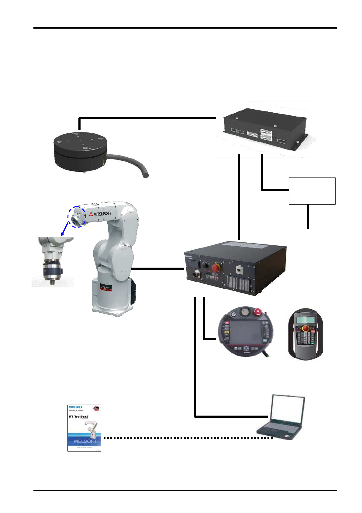
3.2 System Configuration
The device configuration required to use the force sense function is shown below.
Force sensor
(1F-FS001-W200)
(Force sensor
attachment
example)
RT ToolBox2
3D-11C-WINJ
3D-12C-WINJ
Serial cable between unit and sensor
(2F-FSCBL1-05)
Robot controller
Cable between
devices
Robot
LAN, USB
Force sense interface unit
(2F-TZ561)
24 VDC output cable
(2F-PWRCBL-01)
24 VDC power
(2F-PWR-01)
24 VDC input power
Teaching pendant
(R56/57TB or
R32/33TB
Computer
supply
supply cable
(2F-PWRCBL-02)
Fig. 3-1: Force sense function system configuration drawing
System Configuration 3-5

3 Force Sense Function System Specifications
3.3 Force Sense Function Specifications
The force sense function specifications are as follows.
Table 3-1: Force sense function specifications
Item Function Details
Applicable robot RV-F Series / RH-F Series
Robot program language MELFA-BASIC V (with dedicated force sense function commands)
Controller
Force
sense
control
Force
sense
detection
Force
sense
log
R32TB/R33TB
R56TB/R57TB
RT ToolBox2
Stiffness control Function used to control robot softly (Sets stiffness coefficients,
damping coefficients.)
Force control This function controls the robot while pushing with specified force.
Control
characteristics
change
Interrupt execution Interrupt processing can be performed using the status at the point the
Data latch This function obtains the force sensor and robot position at the time of
Data referencing This function displays force sensor data and retains maximum values.
Synchronization data This function obtains force sensor information synchronized with
Start/end triggers Logging start and end commands can be specified in the robot
FTP transfer This function transfers obtained log files to an FTP server.
Force sense control
(TB)
Force sense monitor Displays sensor data and the force sense control setting status.
Teaching position
search
Force sense control
(TB)
Force sense monitor Displays sensor data and the force sense control setting status.
Teaching position
search
Parameter setting
screen
Waveform data
display
Parameter setting
screen
This function changes the control characteristics of force control and
stiffness control during robot movement.
specified force and moment are exceeded.
contact.
position information as log data.
program.
Enables/disables force sensor control and sets control conditions while
jogging.
This function searches for the contact position.
Enables/disables force sense control and sets control conditions while
jogging.
This function searches for the contact position.
Dedicated force sense function parameter setting screen
Displays force sensor and position data.
Dedicated force sense function parameter setting screen
3-6 Force Sense Function Specifications
3 Force Sense Function System Specifications
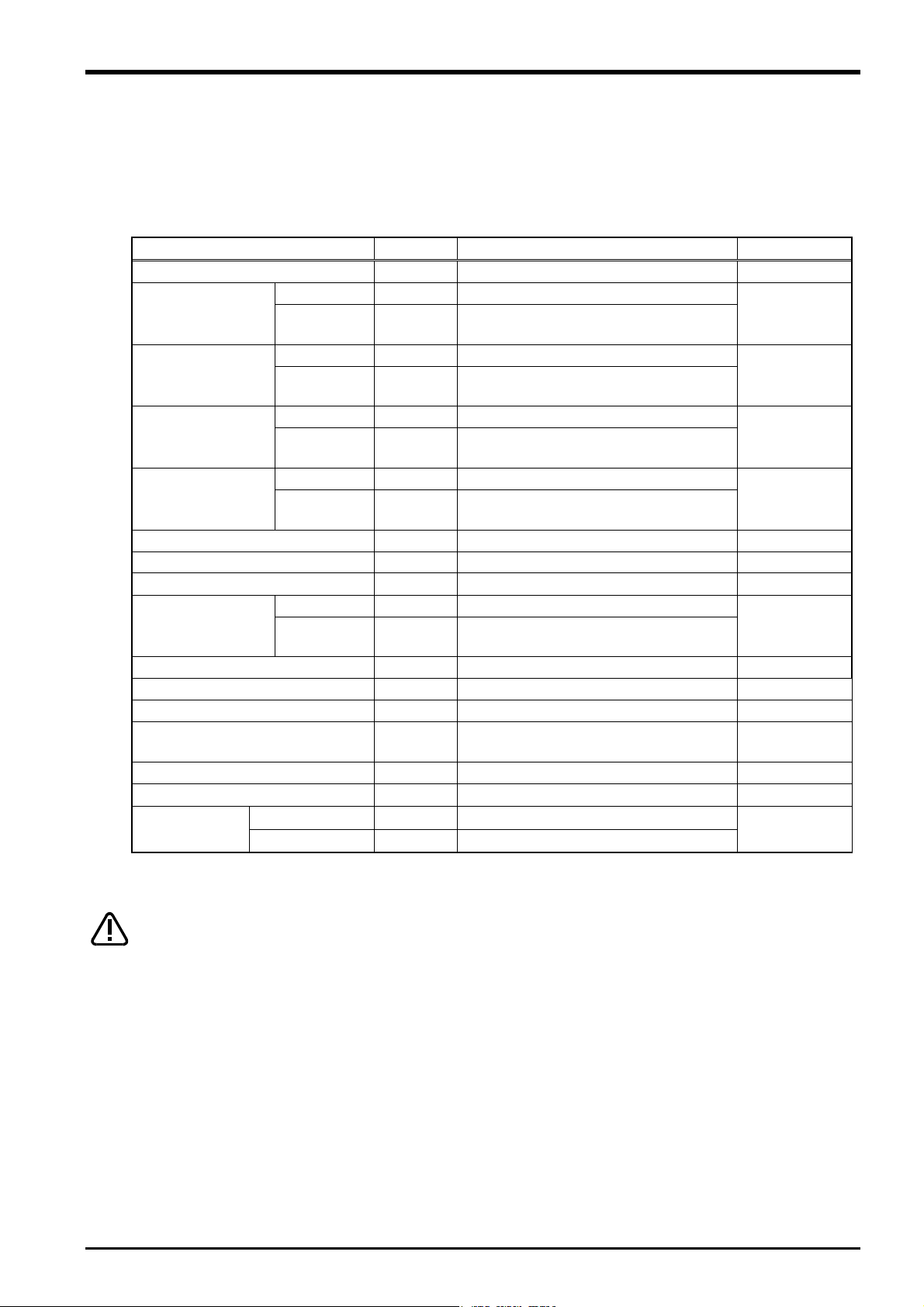
3.4 Force Sense Interface Unit Specifications
The force sense interface unit specifications are as follows.
Table 3-2: Force sense interface unit specifications
Item Unit Specification Value Remarks
Model - 2F-TZ561
Force
sensor
No. of connected
sensors
RS-422
sensors 1
ch 1
For sensor connection Interface
For robot controller and additional axis amp
connection
There should be no momentary power
interruptions or momentary voltage drops.
Includes power supply capacity for force
sensor unit.
Does not include protrusions.
Power
supply
SSCNET III
Input voltage
range
Power
consumption
ch 2
VDC
W 25
External dimensions mm
24 5%
225(W) x 111(D) x 48(H)
Weight kg Approx. 0.8
Construction
Panel installation, open
type
IP20
Operating temperature range °C 0 to 40
Relative humidity %RH 45 to 85 There should be no dew condensation.
Paint color Dark gray Munsell No.: 3.5PB3.2/0.8
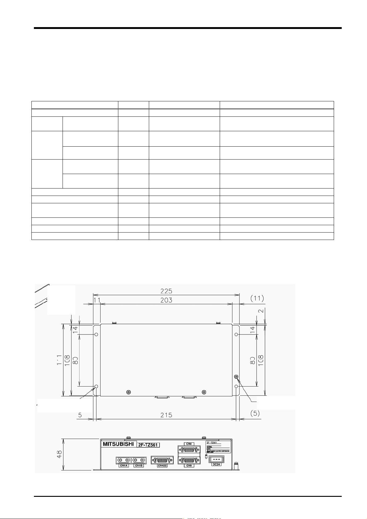
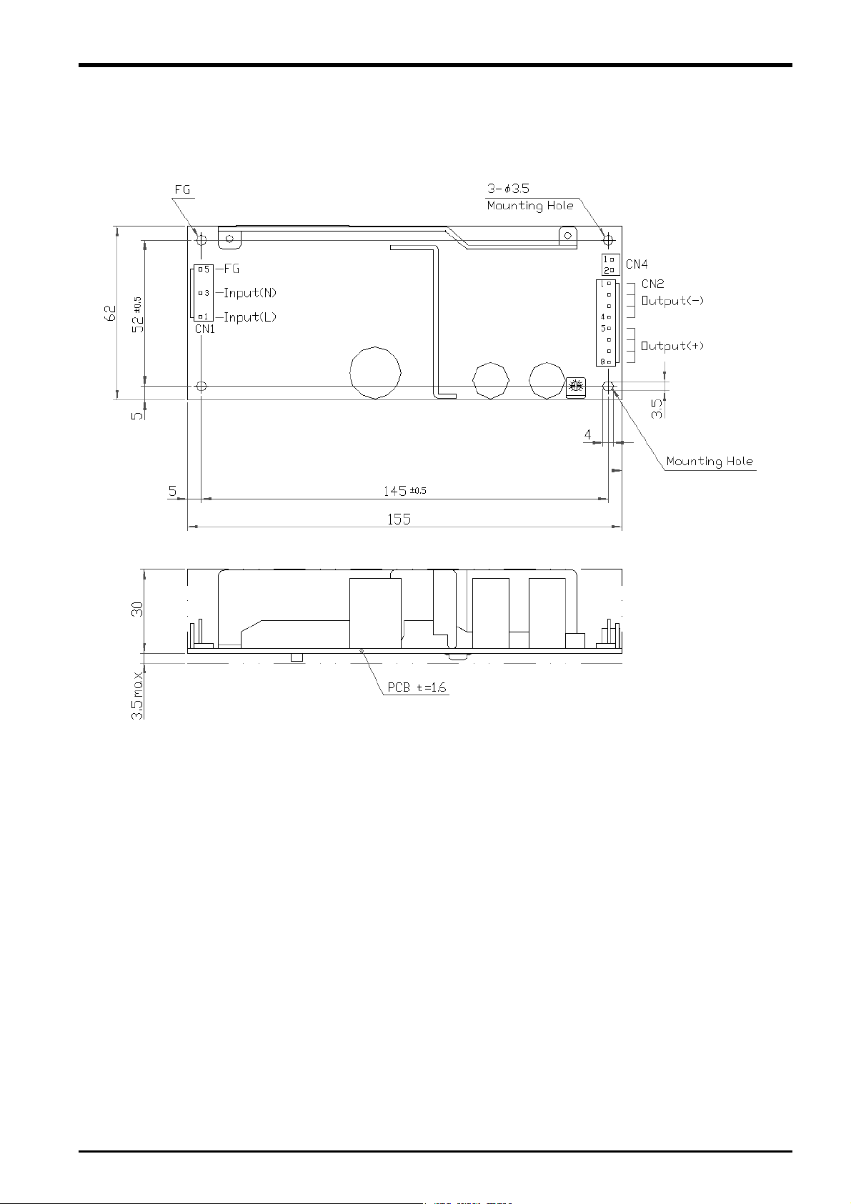
3.4.1 Force Sense Interface Unit External Dimensions
Outline drawings of the force sense interface unit are shown below.
4 - 4.5 hole
FG (M3 screw)
Fig. 3-2: Force sense interface unit outline drawings
Force Sense Interface Unit Specifications 3-7
3 Force Sense Function System Specifications
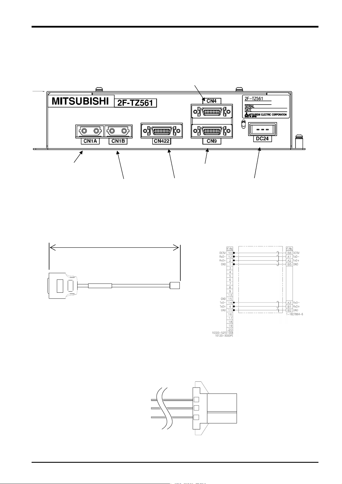
3.4.2 Name of Each Force Sense Interface Unit Part
The name of each force sense interface unit part is as follows.
CN1A
(for robot controller
connection)
CN1B
(for additional axis amp
connection)
(for force sensor
CN4 connector
(not used)
CN9 connector
(not used)
CN422
connection)
DC24 connector
(for power supply)
3.4.3 Force Sensor Connection Cable
5000 mm
3.4.4 24 VDC Output Cable
Connection diagram
(Pin assignment)
1: +24 V
2: 0 V
3: GND
3-8 Force Sense Interface Unit Specifications
3.4.5 24 VDC Power Supply Outline Drawing
3 Force Sense Function System Specifications
Fig. 3-3: 24 VDC power supply outline drawing
Force Sense Interface Unit Specifications 3-9
3 Force Sense Function System Specifications
3.5 Force Sensor Specifications
The force sensor specifications are as follows.
Table 3-3: Force sensor specifications
Item Unit Specification Value Remarks
Model - 1F-FS001-W200
Fx, Fy, Fz N 200
Rated load
Max. static load
*1
Breaking load *2
Resolution
Linearity %FS 3
Hysteresis %FS 5
Other axis sensitivity %FS ±5
temperature
properties
Consumption current mA 200
Output form - RS422
Weight (sensor unit) g 360
External dimensions mm
Material - Aluminum alloy
Color - Black
Operating
environment
*1: Stopper function operating load
*2: Permanent deformation load
Caution
Mx, My,
Mz
Nm 4
Fx, Fy, Fz N 1000
Mx, My,
Mz
Nm 6
Fx, Fy, Fz N 10000
Mx, My,
Mz
Nm 300
Fx, Fy, Fz N Approx. 0.03
Mx, My,
Mz
Nm Approx. 0.0006
Fx, Fy, Fz %FS/°C ±0.2 Zero
Mx, My,
Mz
%FS/°C ±0.2
Temperature °C 0 to 45
Humidity %RH 95 or less
The breaking load is not the load which guarantees sensor operation. If operated up to
even one degree of the breaking load, distortion will occur inside the sensor, and it may
not be possible to detect load properly. Please use within the rate load.
80 x 32.5
See outline
drawing.
3-10 Force Sensor Specifications
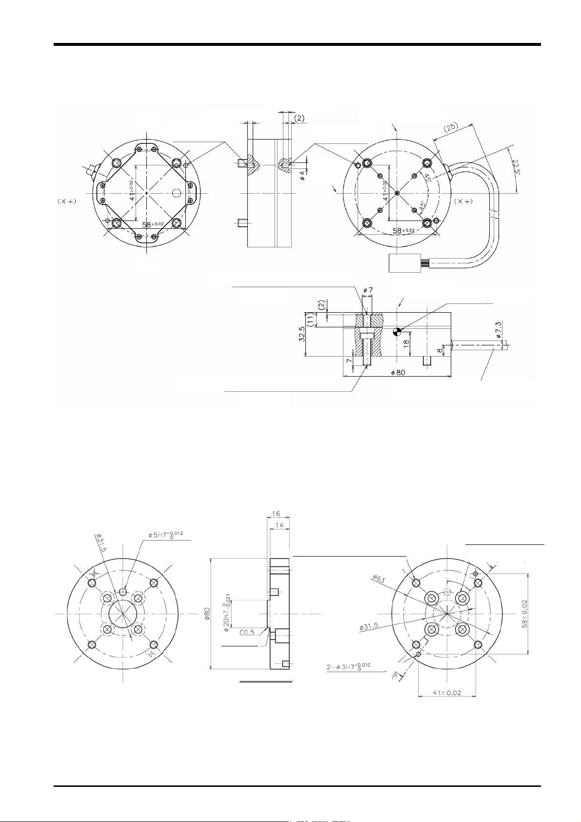
3.5.1 Force Sensor External Dimensions
Outline drawings of the force sensor are shown below.
H7, effective depth 4
(Detection
axis X)
(P.C.D 63)
(Y-)
Positioning pin hole
2 -3 H7, depth 4
(Y+)
H7, effective depth 4
Sensor attachment tapping hole 4 – M6 x 1.0
3 Force Sense Function System Specifications
(Detection axis Y) (Y-)
Positioning pin hole
2 -3 H7, depth 4
(Detection axis Z)
(Z+)
Sensor detection center
Low-head bolt for sensor attachment 4 – M6 x 1.0
(P.C.D 63)
(Cable: MISUMI NA20276RSB-26-5P)
Fig. 3-4: Force sensor outline drawing
3.5.2 Sensor Attachment Adapter External Dimensions
Outline drawings of the sensor attachment adapter are shown below.
depth 6
4 – M6 screw through-hole, bottom hole 4.9
(at equidistant points on circumference)
R0.4 or less
4 – 5.5 cut, 10 through-hole
(at equidistant points on circumference)
A
depth 10
depth 5
Cross-section AA
(sensor positioning pin hole)
Fig. 3-5: Sensor attachment adapter outline drawings
Force Sensor Specifications 3-11

3 Force Sense Function System Specifications
3.6 Coordinate System Definition
The force and moment coordinate systems used with the force sense function are summarized in "Table 3-4".
Table 3-4: Force sense coordinate system list
Coordinate System Name Description
Force sense coordinate system
(mechanical interface)
Force sense coordinate system
(tool)
Force sense coordinate system (XYZ) Coordinate system for force sense function
Force sensor coordinate system Coordinate system for force sensor
A definition of each coordinate system is described below.
Coordinate system that forms reference for calibration
(See section
Coordinate system for force sense function
(when tool selected)
(when XYZ selected)
6.4.2 for details on calibration.)
3-12 Coordinate System Definition
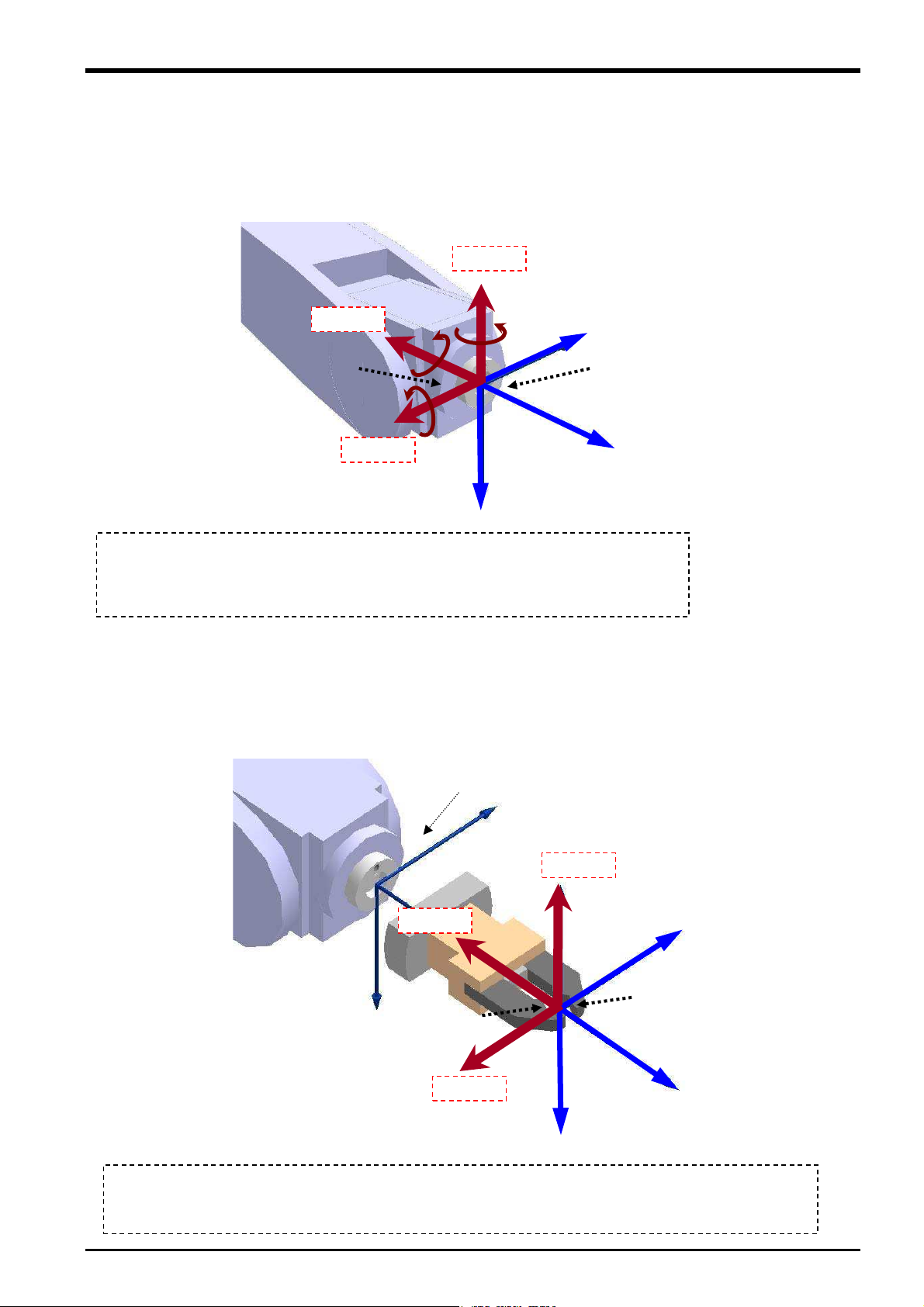
3 Force Sense Function System Specifications
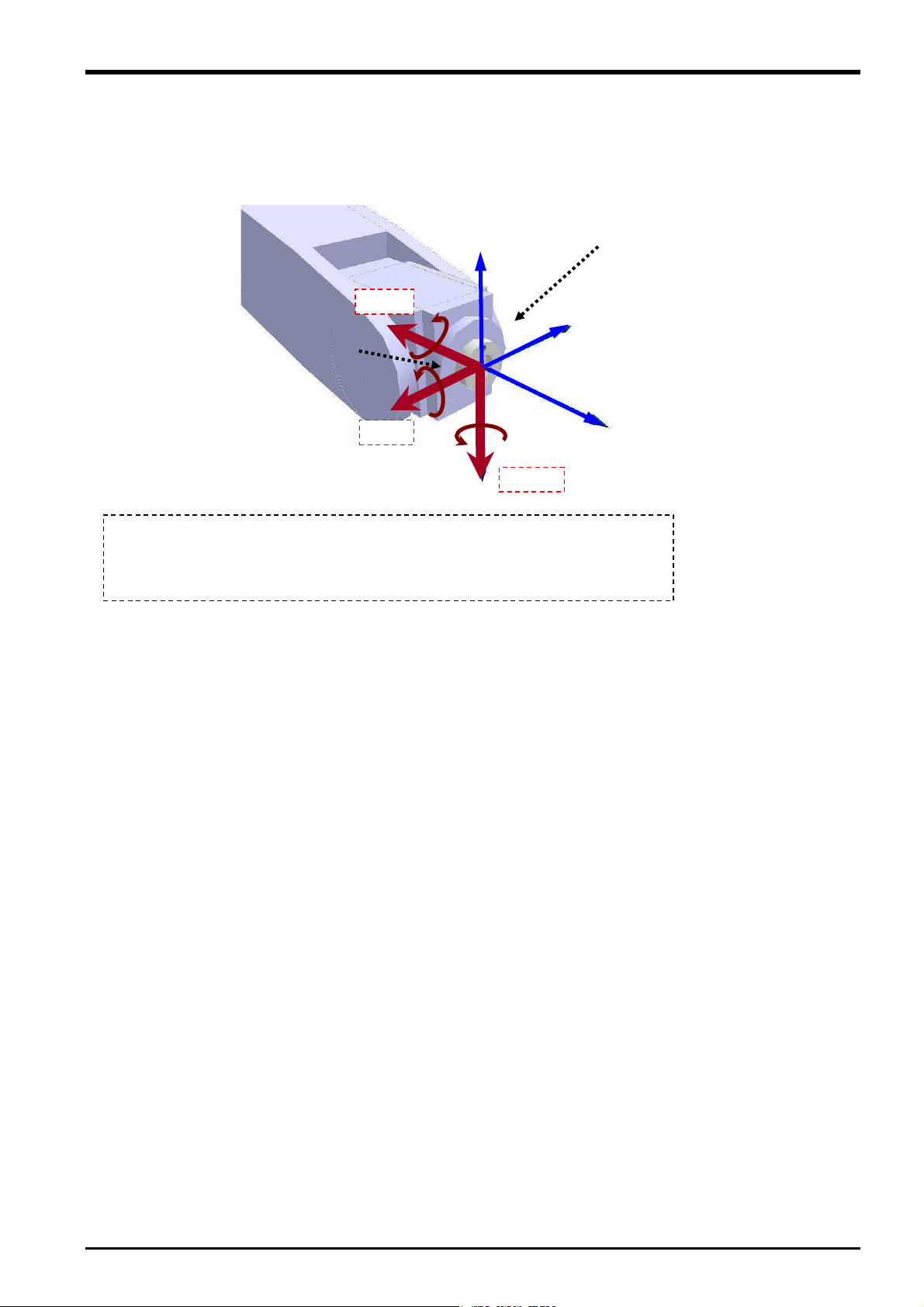
3.6.1 Force Sense Coordinate System (Mechanical Interface)
The force sense coordinate system (mechanical interface) is defined as follows.
+FZm
+MZm
Force sense coordinate
system
(mechanical interface)
+MYm
+FYm
The force sense coordinate system (mechanical interface) is the plus direction coordinate
system for the direction receiving the reaction force when the robot is moved in the
mechanical interface coordinate system plus direction. The coordinate system origin point
overlaps with that of the mechanical interface coordinate system. (In this coordinate system,
the mechanical interface coordinate system symbols are reversed.)
+FXm
+Xm
+MXm
+Ym
Mechanical interface coordinate
system
* Refer to the separate "Detailed
Explanations of Functions and
Operations (BFP-A8586)" for
+Zm
details on the definition of the
mechanical interface coordinate
system.
3.6.2 Force Sense Coordinate System (Tool)
If the tool coordinate system is set, the force sense coordinate system (tool) is defined as follows based on the
set tool coordinate system.
+FZt
Force sense coordinate system
(tool)
The force sense coordinate system (tool) is the plus direction coordinate system for the direction receiving the
reaction force when the robot is moved in the tool coordinate system plus direction. The coordinate system
origin point overlaps with that of the tool coordinate system. (In this coordinate system, the tool coordinate
system symbols are reversed.)
Mechanical interface coordinate system
+FXt
+MXt
+MZt
+MYt
+FYt
+Yt
Tool coordinate system
* Refer to the separate
+Zt
+Xt
"Detailed Explanations of
Functions and Operations
(BFP-A8586)" for details on
the definition of the tool
coordinate system.
Coordinate System Definition 3-13
3 Force Sense Function System Specifications
3.6.3 Force Sense Coordinate System (XYZ)
The assumed force sense coordinate system (XYZ) used in force sense function processing is defined as
follows.
+Z
+FX
+MX
+MX
Force sense coordinate
system (XYZ)
+MY
+MY
+FY
+MZ
+MZ
The force sense coordinate system (XYZ) is the plus direction coordinate system for the
direction receiving the reaction force when the robot is moved in the XYZ coordinate
system plus direction. The coordinate system origin point overlaps with that of the
mechanical interface coordinate system.
XYZ coordinate system (direction only)
* Refer to the separate "Detailed
Explanations of Functions and
Operations (BFP-A8586)" for
+Y
details on the definition of the XYZ
coordinate system.
+X
+FZ
3-14 Coordinate System Definition
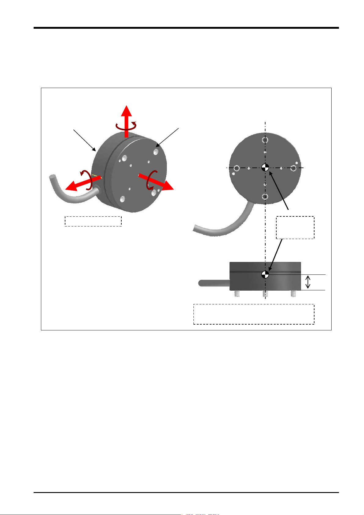
3.6.4 Force Sensor Coordinate System
The force sensor coordinate system is defined as follows.
+FYs
3 Force Sense Function System Specifications
Robot side
+MXs
+FXs
Left-hand system
+MYs
+MZs
Tool side
+FZs
Coordinate
system
origin point
18 mm
The origin point of the force sensor coordinate
system is the position 18 mm away from the
robot side surface.
Coordinate System Definition 3-15
4 Check Before Use
p
4 Check Before Use
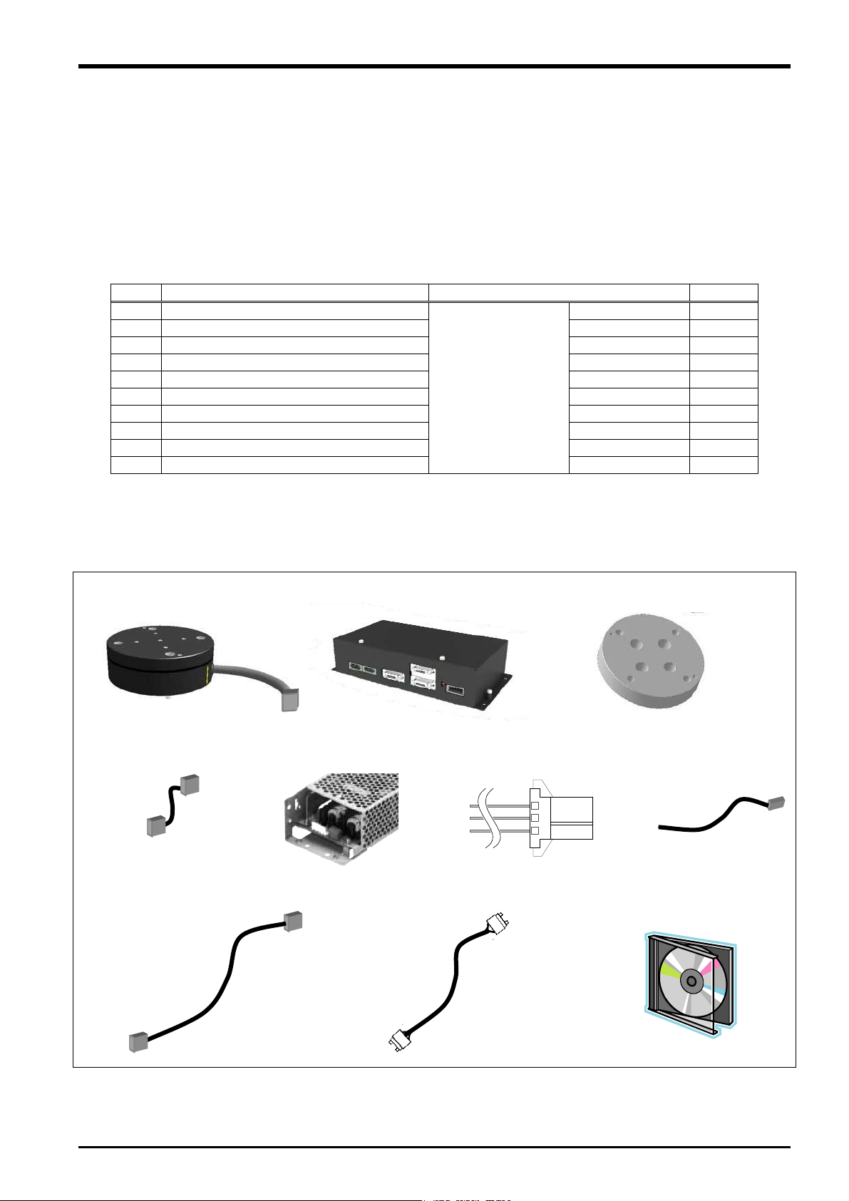
4.1 Product Check
The standard configuration of this product is as follows. Please check.
Table 4-1: Force sensor set product configuration list
No. Part Name Model Quantity
(1) Force sensor 1F-FS001-W200 1
(2) Force sense interface unit 2F-TZ561 1
(3) Sensor attachment adapter (RV-2/4/7F) 1F-FSFLG-01 1
(4) Adapter cable 1F-ADCBL-01 1
(5) 24 VDC power supply 2F-PWR-01 1
(6) 24 VDC power supply output cable 2F-PWRCBL-01 1 m
(7) 24 VDC power supply input cable 2F-PWRCBL-02 1 m
(8) Serial cable between unit and sensor 2F-FSCBL1-05 5 m
(9) SSCNET III cable MR-J3BUS10M 10 m
(10) CD-ROM
Note) The numbers in the above table correspond to the numbers below.
(1) Force sensor (2) Force sense interface unit (3) Sensor attachment adapter
(4) Adapter cable
(5) 24 VDC power supply
(8) Serial cable between unit and sensor (5 m)
4F-FS001-W200
(force sensor set)
(6) 24 VDC power supply
output cable
(9) SSCNET III cable (10 m)
BFP-A8946 1
(7) 24 VDC power supply
input cable
(10)CD-ROM
・Instruction Manual
・Sam
le Program
4-16 Product Check
4 Check Before Use
4.2 Software Versions
All software must support the force sense function to facilitate its use. Check all versions prior to use.
■ Robot controller
Part Name Model Applicable Version
CR750-Q/CR751-Q Ver.R3m or later Controller
CR750-D/CR751-D Ver.S3m or later
■ Teaching pendant
Part Name Model Applicable Version
R56TB/R57TB Ver.3.0 or later Teaching pendant
R32TB/R33TB Ver.1.7 or later
■ Support software
Part Name Model Applicable Version
MELSOFT RT ToolBox2 3D-11C-WINJ
3D-11C-WINE
MELSOFT RT ToolBox2 mini 3D-12C-WINJ
3D-12C-WINE
Ver.2.20W or later
Ver.2.20W or later
Software Versions 4-17
5 Attaching the Force Sensor
5 Attaching the Force Sensor
This Chapter describes how to attach the force sensor. The force sensor is a precision measuring instrument,
and attaching it carelessly may lead to a drop in accuracy or fault. Always check the following before performing
attachment.
Furthermore, it is necessary to correctly define the correlation between the sensor coordinate system and robot
coordinate system. Refer to the recommended attachment method in section
attachment angle.
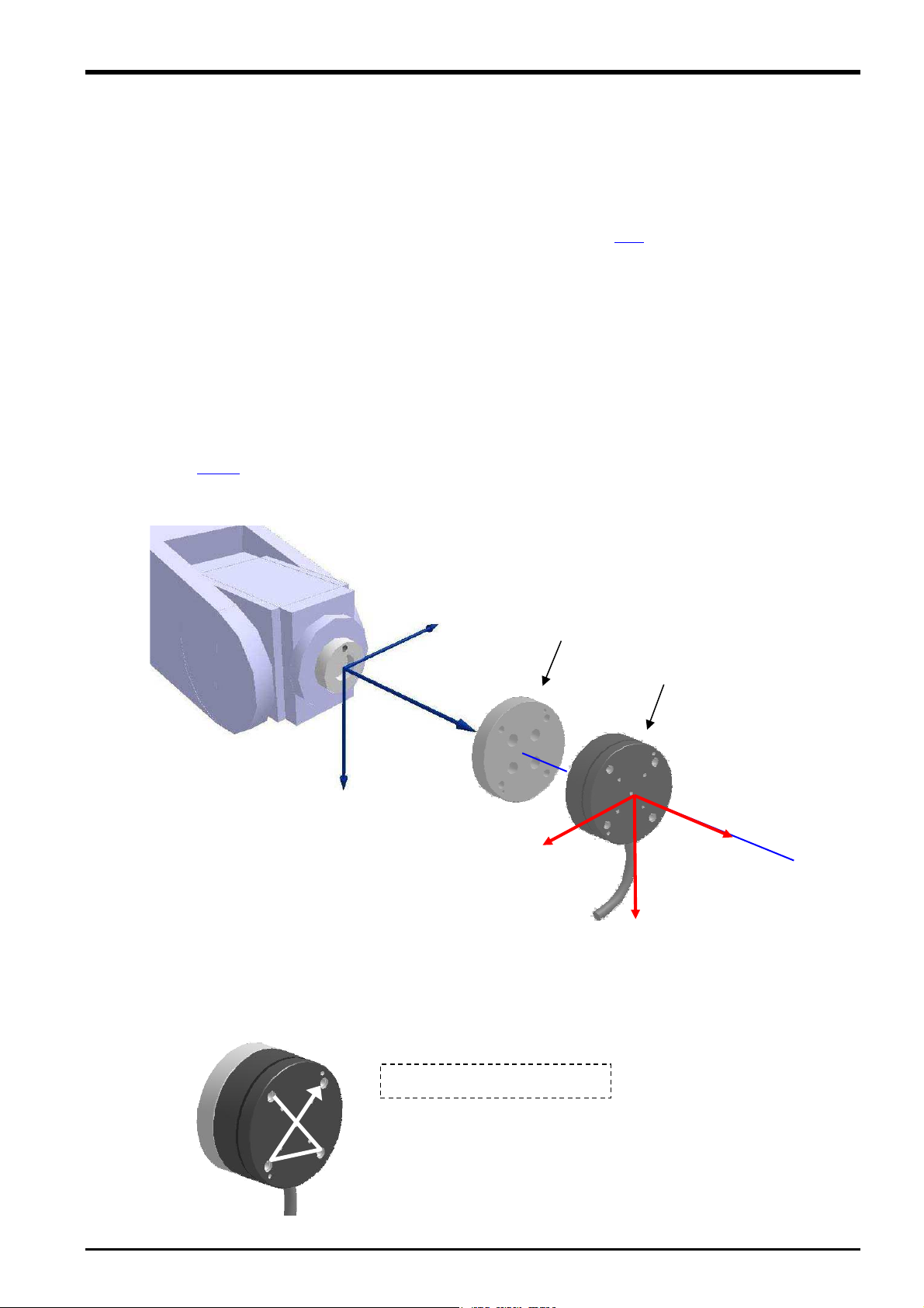
5.1 Attachment Adapter
A dedicated "sensor attachment adapter" is required to secure the force sensor to the robot. As shown in the
following diagram, attach the sensor attachment bracket to the robot mechanical interface before installing the
force sensor.
<If preparing your own attachment adapter>
3.5.1 for details on the attachment shape at the sensor side. Furthermore, refer to the separate
Refer to section
"Standard Specifications" for details on the shape of the robot mechanical interface.
Sensor attachment adapter
+Ym
+Zm
+Xm
+FYs
5.2 Sensor Installation
5.3 for details on the sensor
Force sensor
+FZs
+FXs
The force sensor is secured by tightening the bolts built in to the sensor from the bolt holes on the force sensor
tool side. Tighten each bolt in order diagonally a little at a time to ensure even contact between the sensor
installation surface and sensor attachment adapter. The sensor may be damaged if any of the bolts are overly
tightened at one time, and therefore caution is advised. Always tighten each bolt a little at a time until the
recommended torque value is reached (see below).
5-18 Attachment Adapter
(1)
(3)
(4)
<Tightening torque> 6 N·m
(2)
5 Attaching the Force Sensor
The bolts should also be tightened a little at a time to ensure an even attachment surface when attaching a
hand to the force sensor tool side (Tightening torque: 6 N·m).
Care should also be taken with regard to the following points. If not attached properly, it will not be possible to
obtain force data accurately, leading to a drop in force sense control performance.
Ensure that the hand attachment surface is as flat as possible, and ensure sufficient stiffness to avoid any
loss in force or moment.
Do not attach in such a way as to prevent movement of moveable parts of the force sensor (cable routing
etc.)
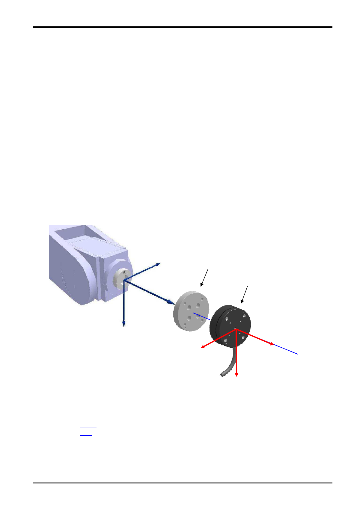
5.3 Recommended Attachment Angle
The following attachment method is recommended to ensure easy calibration with the force sensor coordinate
system and force sense coordinate system (mechanical interface) that forms the reference for the force sense
function.
[Recommended attachment angle]
Attach so that the sensor coordinate system +FXs direction is parallel with the mechanical interface
coordinate system +Xm direction.
Sensor attachment adapter
+Ym
Force sensor
+Zm
+Xm
+FZs
+FYs
+FXs
<Calibration>
To ensure proper functioning of the force sense function, it is necessary to correctly set the correlation between
the force sensor coordinate system and force sense coordinate system (mechanical interface).
* Refer to section
* Refer to section
6.4.2 for details on the calibration method.
3.5 for details on the coordinate system definition.
Recommended Attachment Angle 5-19
6 Device Connection, Wiring, and Settings
6 Device Connection, Wiring, and Settings
This Chapter describes "force sensor", "force sense interface unit", and "robot controller" connection, as well as
default parameter settings.
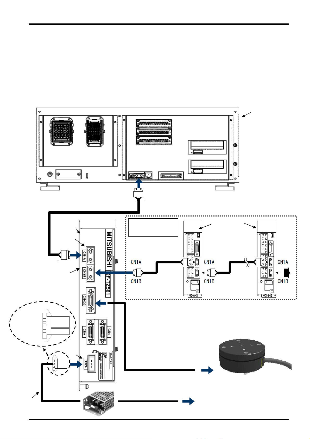
6.1 Force Sense Unit
Robot Controller
Connect the force sense interface unit and robot controller as shown below.
<CR750-D Series>
SSCNET III cable
Connect to ExtOPT connector.
CN1A
When using additional
axis functions
SSCNET III cable
CN1B
CR750-D controller
(rear side)
MR-J3-B
SSCNET III cable
Force sense interface unit
2F-TZ561 (front side)
<Pin
assignment>
1: +24 V
2: 0 V
3: GND
DC24
24 VDC power supply
output cable
6-20 Force Sense Unit ( Robot Controller
Connect to
CN422.
24 VDC power supply
* If using the additional axis function, connect a general-purpose servo
amp after the force sense interface unit. (See "Instruction Manual
Additional Axis Functions" (BFP-A8663) for details on the additional
axis functions
Serial cable between unit and sensor
Force sensor
24 VDC power supply input cable
AC100〜200V
 Loading...