

Mitsubishi Electric CR750-Q, CR750, CR751-Q, CR751-D, CR760-D Instruction Manual
...
Mitsubishi Industrial Robot
CR750/CR751/CR760 Series Controller
INSTRUCTION MANUAL
Detailed explanations of functions and operations
This instruction manual apply to both the CR-750-Q/CR751-Q/CR760-Q controller corresponding
to iQ Platform, and the CR-750-D/CR751-D/CR760-D controller of standalone type.
BFP-A8869-W

All teaching work must be carried out by an operator who has received special
Always read the following precautions and the separate "Safety
Manual" before starting use of the robot to learn the required
measures to be taken.
Safety Precautions
CAUTION
CAUTION
WARNING
CAUTION
DANGER
CAUTION
CAUTION
CAUTION
training. (This also applies to maintenance work with the power source turned
ON.)
Enforcement of safety training
For teaching work, prepare a work plan related to the methods and procedures
of operating the robot, and to the measures to be taken when an error occurs
or when restarting. Carry out work following this plan. (This also applies to
maintenance work with the power source turned ON.)
Preparation of work plan
Prepare a device that allows operation to be stopped immediately during
teaching work. (This also applies to maintenance work with the power source
turned ON.)
Setting of emergency stop switch
During teaching work, place a sign indicating that teaching work is in progress
on the start switch, etc. (This also applies to maintenance work with the power
source turned ON.)
Indication of teaching work in progress
Provide a fence or enclosure during operation to prevent contact of the
operator and robot.
Installation of safety fence
Establish a set signaling method to the related operators for starting work, and
follow this method.
Signaling of operation start
As a principle turn the power OFF during maintenance work. Place a sign
indicating that maintenance work is in progress on the start switch, etc.
Indication of maintenance work in progress
Before starting work, inspect the robot, emergency stop switch and other
related devices, etc., and confirm that there are no errors.
Inspection before starting work
The points of the precautions given in the separate "Safety Manual" are given below.
DANGER
CAUTION
CAUTION
CAUTION
CAUTION
CAUTION
CAUTION
WARNING
WARNING
CAUTION
WARNING
CAUTION
CAUTION
CAUTION
CAUTION
Refer to the actual "Safety Manual" for details.
When automatic operation of the robot is performed using multiple control
devices (GOT, programmable controller, push-button switch), the interlocking of
operation rights of the devices, etc. must be designed by the customer.
Use the robot within the environment given in the specifications. Failure to do
so could lead to a drop or reliability or faults. (Temperature, humidity,
atmosphere, noise environment, etc.)
Transport the robot with the designated transportation posture. Transporting
the robot in a non-designated posture could lead to personal injuries or faults
from dropping.
Always use the robot installed on a secure table. Use in an instable posture
could lead to positional deviation and vibration.
Wire the cable as far away from noise sources as possible. If placed near a noise
source, positional deviation or malfunction could occur.
Do not apply excessive force on the connector or excessively bend the cable.
Failure to observe this could lead to contact defects or wire breakage.
Make sure that the workpiece weight, including the hand, does not exceed the
rated load or tolerable torque. Exceeding these values could lead to alarms or
faults.
Securely install the hand and tool, and securely grasp the workpiece. Failure to
observe this could lead to personal injuries or damage if the object comes off or
flies off during operation.
Securely ground the robot and controller. Failure to observe this could lead to
malfunctioning by noise or to electric shock accidents.
Indicate the operation state during robot operation. Failure to indicate the state
could lead to operators approaching the robot or to incorrect operation.
When carrying out teaching work in the robot's movement range, always secure
the priority right for the robot control. Failure to observe this could lead to
personal injuries or damage if the robot is started with external commands.
Keep the jog speed as low as possible, and always watch the robot. Failure to do
so could lead to interference with the workpiece or peripheral devices.
After editing the program, always confirm the operation with step operation
before starting automatic operation. Failure to do so could lead to interference
with peripheral devices because of programming mistakes, etc.
Make sure that if the safety fence entrance door is opened during automatic
operation, the door is locked or that the robot will automatically stop. Failure to
do so could lead to personal injuries.
Never carry out modifications based on personal judgments, or use nondesignated maintenance parts.
Failure to observe this could lead to faults or failures.
When the robot arm has to be moved by hand from an external area, do not
WARNING
CAUTION
CAUTION
DANGER
DANGER
DANGER
DANGER
DANGER
CAUTION
place hands or fingers in the openings. Failure to observe this could lead to
hands or fingers catching depending on the posture.
Do not stop the robot or apply emergency stop by turning the robot controller's
main power OFF. If the robot controller main power is turned OFF during
automatic operation, the robot accuracy could be adversely affected. Moreover,
it may interfere with the peripheral device by drop or move by inertia of the arm.
Do not turn off the main power to the robot controller while rewriting the
internal information of the robot controller such as the program or parameters.
If the main power to the robot controller is turned off while in automatic
operation or rewriting the program or parameters, the internal information of the
robot controller may be damaged.
Do not connect the Handy GOT when using the GOT direct connection function
of this product. Failure to observe this may result in property damage or bodily
injury because the Handy GOT can automatically operate the robot regardless
of whether the operation rights are enabled or not.
Do not connect the Handy GOT to a programmable controller when using an iQ
Platform compatible product with the CR7xx-Q controller. Failure to observe
this may result in property damage or bodily injury because the Handy GOT can
automatically operate the robot regardless of whether the operation rights are
enabled or not.
Do not remove the SSCNET III cable while power is supplied to the multiple
CPU system or the servo amplifier. Do not look directly at light emitted from
the tip of SSCNET III connectors or SSCNET III cables of the Motion CPU or
the servo amplifier. Eye discomfort may be felt if exposed to the light.
(Reference: SSCNET III employs a Class 1 or equivalent light source as
specified in JIS C 6802 and IEC60825-1 (domestic standards in Japan).)
Do not remove the SSCNET III cable while power is supplied to the controller.
Do not look directly at light emitted from the tip of SSCNET III connectors or
SSCNET III cables. Eye discomfort may be felt if exposed to the light.
(Reference: SSCNET III employs a Class 1 or equivalent light source as
specified in JIS C 6802 and IEC60825-1 (domestic standards in Japan).)
Attach the cap to the SSCNET III connector after disconnecting the SSCNET
III cable. If the cap is not attached, dirt or dust may adhere to the connector
pins, resulting in deterioration connector properties, and leading to malfunction.
Make sure there are no mistakes in the wiring. Connecting differently to the way
specified in the manual can result in errors, such as the emergency stop not
being released. In order to prevent errors occurring, please be sure to check
that all functions (such as the teaching box emergency stop, customer emergency stop, and door switch) are working properly after the wiring setup is completed.

Use the network equipments (personal computer, USB hub, LAN hub, etc)
CAUTION
confirmed by manufacturer. The thing unsuitable for the FA environment
(related with conformity, temperature or noise) exists in the equipments
connected to USB. When using network equipment, measures against the noise,
such as measures against EMI and the addition of the ferrite core, may be
necessary. Please fully confirm the operation by customer. Guarantee and
maintenance of the equipment on the market (usual office automation
equipment) cannot be performed.
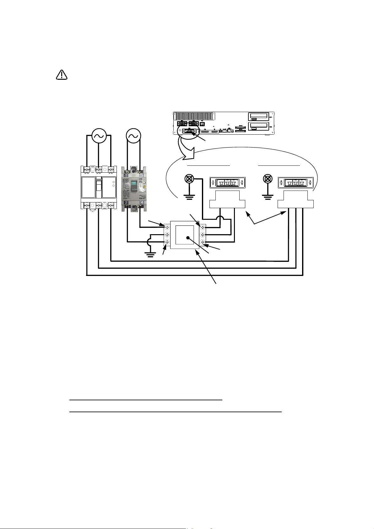
*CR751-D or CR751-Q controller
CAUTION
PE terminal
Grounding screw
Controller
ACIN connector
AC200V AC200V
Primary
Secondary
PE terminal
Grounding screw
123 123
ACIN connector
ACIN connector
Note 2)
Note 1) Crimping swage is recommended for connecting the attachment ACIN connector (soldering is also possible)
Recommendation compression tools: 234171-1(Tyco Electronics)
Note 2) The earth leakage breaker is the customer preparation. Always use the cover below.
Recommendation: For single primary power supply .........NV30FAU-2P-10A-AC100-240V-30mA, (Cover: TCS-05FA2)
For three primary power supply .......... NV30FAU-3P-10A-AC100-240V-30mA, (Cover: TCS-05FA3)
Note 3) If necessary, as shown in the figure, connects the noise filter between ACIN terminal blocks and primary power supply.
(Recommended noise filter: SUP-EL20-ER6 *OKAYA ELECTRIC INDUSTRIES)
Controller
<4> LINE/LOAD
<3> LINE/LOAD
<1> LINE/LOAD
<2> LINE/LOAD
Noise filter
Label
ACIN connector or
power cable
(Attachment)
Note 1)
For three phaseFor single phase
Three phase Single phase
Earth leak-
age breaker
(NV)
Note 3)
* The controller is an
example.
Notes of the basic component are shown.
Please install the earth leakage breaker in the primary side supply power supply
of the controller of CR751-D or CR751-Q because of leakage protection.
1) Please prepare the following: Leakage current breaker (with the terminal cover), cable for connecting the
primary power supply (AWG #14 (2mm
2
or above).
(3.5mm
The secondary power cable (with the ACIN connector) for single phase or three phase power is supplied with
the product to match the specifications. When you build a cable suitable for your environment using the ACIN
connector and the ACIN terminal supplied, prepare a secondary power cable (AWG #14 (2mm
2) Confirm that the primary power matches the specifications.
3) Confirm that the primary power is OFF and that the earth leakage breaker power switch is OFF.
4) Connect the secondary power cable.
a) When using the supplied power cable with the ACIN connector
Refer to the figure above and connect the cable from the secondary side of the earth leakage breaker.
b) When building a power cable using the ACIN connector and the ACIN terminals supplied
Connect the ACIN terminals with the secondary power cable (prepared by customers), and insert the ACIN
terminals to the ACIN connector pins with the following numbers. Crimping caulking is recommended to
connect the ACIN terminals.
For single phase: 1 and 3
For three phase: 1, 2, and 3
Refer to the figure above and connect the cable from the secondary side of the earth leakage breaker.
5) Connect this ACIN connector to the ACIN connector on the front of the controller.
6) Connect the grounding cable to the PE terminal. (M4 screw)
7) Connect the primary power cable to the primary side terminal of the earth leakage breaker.
2
or above), cables to ground the primary power supply (AWG #12
2
) or above).

Revision history
Date Specifications No. Details of revisions
2012-03-13 BFP-A8869 • First print
2012-04-06 BFP-A8869-A • Error in writing correction (4.3.2 Executing a multitask)
• The example program for collision detection level setting was added (J_ColMxl).
2012-07-26 BFP-A8869-B • Notes were added to the hand and the workpiece condition parameter.
2012-10-03 BFP-A8869-C • In the interference avoidance function, the cylinder was added to the shape of a
simulated component, and the RV-F series was added to the target type.
• RV-F series was added to the setting value at shipment of the collision detection
parameter COL. (Table 5-21)
2012-11-12 BFP-A8869-D • The statement about trademark registration was added.
2013-01-09 BFP-A8869-E • The reference program of J_ColMxl was corrected (error in writing)
2013-03-25 BFP-A8869-F • The explanation of RV-13F series were added. (Operation of the brake release.)
2013-09-20 BFP-A8869-G • The minimum values of CmpG was corrected. (For Cmp Jnt)
2014-01-06 BFP-A8869-H • The explanations of RV-4FJL (5-axis type) were added.
2014-03-31 BFP-A8869-J • The explanation of Spline interpolation function was added.
2014-04-23 BFP-A8869-K • The description of [Reference Program] of status variables M_In32 and M_Out32
2014-08-06 BFP-A8869-M • The cover and corporate logo mark of this manual was changed
• The initial value of parameter OLTMX was corrected.
• The explanation of parameter MEGDIR, MELTEXS were added.
• The vertical multi-joint type robot's structure flag was added.
• The descriptions about RH-3FHR series were added.
• The explanation of parameter CMPJCLL was added.
• The explanation of J1OFFSET parameter was added.
• The explanations of robot status variable were corrected. (C_Mecha, C_Prg)
• The procedure of robot type resetting was added.
• The SpdOpt command and the SPDOPT parameter, and the cylinder limit function
(MECAR parameter) were added.
• The descriptions of Def Act and Return commands were corrected. (A linked page)
• Note was added to the explanation of Output signal reset pattern.
• The explanation of program selection rights setting were modified.
• Origin points were added to "Fig. 4-3: Base conversion".
• Commands which requires a control right by GetM command were listed.
• Errors of an output condition of EMGERR were added.
• The explanation of HANDENA parameter is modified.
• The explanations were added to the parameters of OVRDTB and OVRDENA.
• The example of program in “Table 6-1: Overall I/O signal map” was corrected.
(Formerly: If M_In(900) Then M_Out(900)=1)
• The explanation is added to the If...Then...Else...EndIf command.
• The Reference Program of M_Uar was corrected.
• The Note was added to the parameters of ROMDRV and CTN. (High-speed RAM
mode and Continue function cannot be used together.)
• The NETIP parameter factory setting value for FQ series was added.
• The error described in the explanation of the function of an AUTOENA parameter
was corrected to L5010.
• The description about the program capacity which is likely to cause misunderstanding was deleted.
• Explanation(4) to (6) were added to Mvs command.
• The factory shipment signal number (output) in "Table 6-6:Table of dedicated input/
output" of parameters was corrected.
• The explanation of Ex-T control function was added.
• The OPTOVC parameter was added.
• X and Y axis elements of RV-4FJL in “Table 5-8: Valid axis elements of the tool conversion data depending on the robot mode” were corrected to △ .
• The parameters were added. (WTHFUNC, MVTERM, ESCMODE, PRGMODE,
SVDATA)
• The robot status variable is added. (M_LdFMax)
• The explanation of a free plane limit was complemented.
• The explanation of WthIf command was complemented.
were corrected.

Date Specifications No. Details of revisions
2014-08-21 BFP-A8869-N • Correction of errors.
• The explanation of R56/57TB in “3.10 Operation to Temporarily Reset an Error that
Cannot Be Canceled”.
• Dedicated input/output were added. (DOORSTS1, DOORSTS2, DOORSTS)
• The robot status variable is added. (M_ErCode, M_DIn32, M_DOut32)
• The explanation of Error, Act commands were modified.
• An example was added to Fine P command.
• The explanation of XClr command was modified.
• The functions of ACos and ASin were added.
2014-12-24 BFP-A8869-P • The JOGMENO parameter was added.
• The explanation to specify M_OPOvrd was added.
• In "5.11 Automatic execution of program at power up", the setting value of the
parameter ALWENA was corrected from "7" into "1" and step 17 was added to the
sample program.
• Correction of errors.
CallP command (Error: Speed is valid in a sub program)
SLOTINIT (Error: Do not function in the stop input state (when STOPSTS is ON).)
The lamp which blinks while the T/B is displaying the <OPERATION> screen in the
"ATUOMATIC" mode. (Error: [TB ENABLE] switch)
Table 6-7:Validity state of dedicated input signals (Error: SLOTINIT does not function in the stop input state (when STOPSTS is ON).)
• The explanation and the reference program about Break command were added to
For - Next and While - WEnd commands.
• The explanation when using skip command was added to WithIf command.
• The corporate logo mark of illustrations in this manual was changed.
• The explanation of Fine command was added.
2015-02-05 BFP-A8869-R • Correction of errors in XLoad command. (Error: A program name can be specified
2015-03-10 BFP-A8869-S • The explanation of NETIP parameter was modified.
2015-10-30 BFP-A8869-T • The explanation of commands were modified. (Def Plt, Wait, Cmp Off)
2016-04-07 BFP-A8869-U • The explanation of the get-position-quick function was added.
also at the character string variables.)
• “Table 5-13: Port number to use” was added.
• The new function of S/W Ver.R5q (F-Q series) / S5q (F-Q series) was added.
Type resetting operation by T/B or RT ToolBox2 was added.
• The parameters (DRVMODE, NVJBTOUT) were added.
• The robot status variable is added. (M_RCInfo)
• The explanation parameters were modified. (NETIP, UER1 to USR20, J1OFFSET)
• The commands were added. (EMvSpl, SplWrt, SplFWrt)
• The robot status variables were added. (M_ESpd, P_ECord)
• The functions were added. (SplSpd, SplPos, SplECord)
• “7.3 Spline interpolation” was modified.
• The parameter CATEGORY was added.
• The explanation of collision detection function was modified.
• The explanation of interference avoidance function was modified.
• The explanation of RV-50F series (RV-35F, RV-50F, RV-70F) were added.
• The explanation of RV-2FL was added to the parameter MVTERM.
• Correction of errors in Ovrd command. (Error: This instruction specifies the speed
of robot movement as a value in the range from 1 to 100%.)
• The explanation of M_Open was modified.
• Correction of errors in output signal reset pattern. (Error: ORST0 to ORST224)
• The explanation of Cooperation movement function was modified.
• Explanation of Def Plt, Spd, and Accel commands were modified.
• Parameters were added. (TBBZR, CTERME11 to 19, IOFIL, PRGDUP, AUTOSAVE, NETPSPEC, NETTERM, GOTPORT, OPNOOVRD, EHnPCM1 to 32,
EHnTCM1 to 32, EBRDTAG, EBWRTAG, OPSCRSPD, ALIGNTYP, MEXSBS,
MEXSTL, FBGAIN, PRGDPNTM, MOHW, MEINST, MEINSZ, MEOFFZ, MEINSD,
WKJOGNO, COLSERVO, HNDT, MFENA, MFWRNDAY, MFOPTIME, SRVSIM,
BRKLOCK)
• Parameters were deleted. (BACKUP, REATORE)
• The explanation of ColChk command was added.

Date Specifications No. Details of revisions
2016-09-09 BFP-A8869-V • "7.3 Spline interpolation" was complemented.
• Upgrade of the servo software was added.
• PVSCal command and parameter VSCALBn were added.
• A caution against performing relative calculation for 5-axis robots was added.
• The SKIP input was added to “Table 6-1: Overall I/O signal map”.
• The description of DWord (32 bits) was added to the Def IO command.
• The setting range of the designated speed was added to the Spd command.
• The description of the robot status variables J_Fbc/J_AmpFbc was added to (4) of
[Explanation].
2017-05-10 BFP-A8869-W • Description about the operation when a CPU error occurred in a PLC was added.
• Contact information of the authorized representative was updated.

*Introduction
• No part of this manual may be reproduced by any means or in any form, without prior consent
from Mitsubishi.
• The details of this manual are subject to change without notice.
• An effort has been made to make full descriptions in this manual. However, if any discrepancies
or unclear points are found, please contact your dealer.
• The information contained in this document has been written to be accurate as much as possible. Please interpret that items not described in this document "cannot be performed." or
"alarm may occur".
Please contact your nearest dealer if you find any doubtful, wrong or skipped point.
• This specifications is original.
• The ETHERNET® is a registered trademark of the Xerox Corp.
• AutoCAD® is a registered trademark of Autodesk, Inc. in the U.S. and other countries.
• All other company names and production names in this document are the trademarks or registered trademarks of their respective owners.
Copyright(C) 2012-2017 MITSUBISHI ELECTRIC CORPORATION
Notice
*ONLY QUALIFIED SERVICE PERSONNEL MAY INSTALL OR SERVICE THE ROBOT SYSTEM.
*ANY PERSON WHO PROGRAM, TEACHES, OPERATE, MAINTENANCE OR REPAIRS THE ROBOT
SYSTEM IS TRAINED AND DEMONSTRATES COMPETENCE TO SAFELY PERFORM THE
ASSIGNED TASK.
*ENSURE COMPLIANCE WITH ALL LOCAL AND NATIONAL SAFETY AND ELECTRICAL CODES
FOR THE INSTALLATION AND OPERATION OF THE ROBOT SYSTEM.
Thank you for purchasing the Mitsubishi industrial robot.
This instruction manual explains the functions and operation methods of the robot controller and
teaching pendant (R32TB/R33TB (option)), and the functions and specifications of the MELFABASIC V programming language.
Apply to both the CR750-Q/CR751-Q/CR760-Q series controller corresponding to iQ Platform, and
the CR750-D/CR751-D/CR760-D series controller. Especially the function added individually is indicated to be "CR750-Q" and "CR750-D."
Also in this instruction manual, operation of robot programs such as start-up and shutdown are
explained based on key operations using the operation panel at the front of the controller. In the
case of using a robot that has not been mounted with an operation panel, these operations are carried out using external signals (exclusive input/output signals). The exclusive input/output signals
corresponding to the operation panel are summarized on the following page. Using the parameter
settings, please assign exclusive input/output signals to general purpose input/output signals.
Always read through this manual before starting use to ensure correct usage of the robot.
As much as possible, we have tried to include all special operations in this instruction manual.
Please assume that operations not included in this manual are "not possible".
Note that this document is prepared for the following software versions.
Controller : Version
CR750-Q/CR751-Q/CR760-Q: R5q or later
CR750-D/CR751-D/CR760-D: S5q or later
T/B : Version 1.7 or later

For users operating robots that have not been mounted with an operation panel:
Operation of robot programs such as start-up and shutdown are carried out using external signals
(exclusive input/output signals). This instruction manual is based on robots that are mounted with an
operation panel at the front of the controller, and these operations are explained using key operations on that panel. Using the parameter settings, please assign exclusive input/output signals that
correspond with each key operation to general purpose input/output signals, and operate the robot
using signal operations.
The following table details exclusive input/output signals that correspond with the key operations of
the operation panel explained in this manual. Please use this as a reference to assign signals and
operate the robot.
For further details regarding parameters please see Page 559, "6.3 Dedicated input/output", for the
time chart of each signal please see Page 572, "6.5 External signal timing chart", and for instructions on how to set parameters please see Page 83, "3.15 Operation of parameter screen".
Table: Conversion table of the buttons and dedicated I/O signals
Operation panel
button, lamp
START button
START button lamp
STOP button
STOP button lamp
RESET button
RESET button lamp
CHNG DISP button
UP/DOWN button
END button
END button lamp
SVO.ON button
SVO.ON button lamp
SVO.OFF button
SVO.OFF button lamp
Parameter
name
START Input Starts a program. 3,0
STOP Input Stops a program. 0,-1
ERRRESET Input Releases the error state. 2,2
SLOTINIT Input Cancels the paused status of the program and brings the exe-
PRGSEL Input Selects the value inputted into the signal assigned to the numer-
PRGOUT Input Outputs the program number selected to the signal assigned to
OVRDSEL Input Sets the value inputted into the signal assigned to the numerical
OVRDOUT Input Outputs the override value to the signal assigned to the numeri-
LINEOUT Input Outputs the current line number to the signal assigned to the
ERROUT Input Outputs the error number to the signal assigned to the numerical
IODATA Input Reads the program number and the override value as a binary
CYCLE Input Starts the cycle stop. -1,-1
SRVON Input Turns ON the servo power supply. 4,1
SRVOFF Input Turns OFF the servo power supply. 1,-1
Class Function
Output Indicates that a program is being executed.
Output Indicates that the program is paused.
Output Indicates that an error has occurred.
cuting line to the top. Executing a program reset makes it possible to select a program.
Output
Output -
Output Indicates outputting the program number to the numerical out-
Output -
Output Indicates outputting the override value to the numerical output.
Output Indicates outputting the current line number to the numerical
Output Indicates outputting the error number to the numerical output.
Output Outputs the program number, line number and override value as
Output Outputs that the cycle stop is operating.
Output Indicates the servo power supply is ON.
Output This output indicates a status where the servo power supply
Outputs that in the program selection enabled state.
ical input as a program number.
the numerical output.
put.
input as a override.
cal output.
numerical output.
output.
output.
value.
a binary value.
cannot be turned ON. (Echo back)
Default
setting
-1,-1
-1,
-1,-1
-1,
-1,-1
-1,-1
-1,-1
-1,-1,
-1,-1

Contents
Page
1 Before starting use .......................................................................................................................... 1-1
1.1 Using the instruction manuals ................................................................................................... 1-1
1.1.1 The details of each instruction manuals ............................................................................. 1-1
1.1.2 Symbols used in instruction manual ................................................................................... 1-2
1.2 Safety Precautions .................................................................................................................... 1-3
1.2.1 Precautions given in the separate Safety Manual .............................................................. 1-4
2 Explanation of functions .................................................................................................................. 2-6
2.1 Operation panel (O/P) functions (CR750 controller) ................................................................. 2-6
2.2 Operation panel (O/P) functions (CR760 controller) ................................................................. 2-8
2.3 Teaching pendant (T/B) functions ........................................................................................... 2-10
2.3.1 Operation rights ................................................................................................................ 2-11
2.4 Functions Related to Movement and Control ......................................................................... 2-12
3 Explanation of operation methods ................................................................................................ 3-14
3.1 Operation of the teaching pendant menu screens .................................................................. 3-14
(1) Screen tree ..................................................................................................................... 3-14
(2) Input of the number/character ........................................................................................ 3-18
(3) Selecting a menu ............................................................................................................ 3-19
3.2 Jog Feed (Overview) ............................................................................................................... 3-21
3.2.1 Types of jog feed .............................................................................................................. 3-21
3.2.2 Speed of jog feed .............................................................................................................. 3-22
3.2.3 JOINT jog .......................................................................................................................... 3-23
3.2.4 XYZ jog ............................................................................................................................. 3-23
3.2.5 TOOL jog .......................................................................................................................... 3-24
3.2.6 3-axis XYZ jog .................................................................................................................. 3-24
3.2.7 CYLNDER jog ................................................................................................................... 3-25
3.2.8 WORK jog ......................................................................................................................... 3-25
3.2.9 Switching Tool Data .......................................................................................................... 3-26
3.2.10 Changing the world coordinate (specifies the base coordinate number) ........................ 3-27
3.2.11 Impact Detection during Jog Operation .......................................................................... 3-28
(1) Impact Detection Level Adjustment during Jog Operation ............................................. 3-29
3.3 Opening/Closing the Hands .................................................................................................... 3-30
3.4 Returning to the Safe Point ..................................................................................................... 3-31
3.5 Aligning the Hand .................................................................................................................... 3-32
3.6 Programming .......................................................................................................................... 3-34
3.6.1 Creating a program ........................................................................................................... 3-34
(1) Opening the program edit screen ................................................................................... 3-34
(2) Creating a program ........................................................................................................ 3-35
(3) Completion of program creation and saving programs .................................................. 3-37
(4) Correcting a program ..................................................................................................... 3-38
(5) Registering the current position data .............................................................................. 3-40
(6) Deletion of the position variable ..................................................................................... 3-43
(7) Confirming the position data (Position jump) .................................................................. 3-44
(8) Correcting the MDI (Manual Data Input) ........................................................................ 3-45
(9) Executing a Command Directly ...................................................................................... 3-46
3.7 Debugging ............................................................................................................................... 3-47
(1) Step feed ........................................................................................................................ 3-47
(2) Step return ...................................................................................................................... 3-48
(3) Step feed in another slot ................................................................................................ 3-49
(4) Step jump ....................................................................................................................... 3-51
3.8 Automatic operation ................................................................................................................ 3-52
3.8.1 Setting the operation speed .............................................................................................. 3-52
(1) Operating with the controller .......................................................................................... 3-52
(2) Operating with the T/B .................................................................................................... 3-52
3.8.2 Selecting the program No. ................................................................................................ 3-52
i

Contents
Page
3.8.3 Starting automatic operation ............................................................................................. 3-53
(1) Starting by O/P ............................................................................................................... 3-53
(2) Starting from the T/B ...................................................................................................... 3-54
3.8.4 Stopping ............................................................................................................................ 3-57
(1) Operating with the controller .......................................................................................... 3-57
(2) Operating with the T/B .................................................................................................... 3-57
3.8.5 Resuming automatic operation from stopped state .......................................................... 3-58
(1) Resuming by O/P ........................................................................................................... 3-58
(2) Resuming from T/B ........................................................................................................ 3-58
3.8.6 Resetting the program ...................................................................................................... 3-59
(1) Operating with the controller .......................................................................................... 3-59
(2) Operating with the T/B .................................................................................................... 3-59
3.9 Turning the servo ON/OFF ..................................................................................................... 3-60
3.10 Error reset operation ............................................................................................................. 3-61
3.11 Operation to Temporarily Reset an Error that Cannot Be Canceled ..................................... 3-61
3.12 Operating the program control screen .................................................................................. 3-62
(1) Program list display ........................................................................................................ 3-62
(2) Copying programs .......................................................................................................... 3-63
(3) Name change of the program (Rename) ........................................................................ 3-64
(4) Deleting a program (Delete) ........................................................................................... 3-65
(5) Protection of the program (Protect) ................................................................................ 3-66
(6) Select the program ......................................................................................................... 3-67
3.13 Operation of operating screen .............................................................................................. 3-68
3.13.1 Display of the execution line ........................................................................................... 3-68
(1) Select the confirmation menu ......................................................................................... 3-68
(2) Step feed ........................................................................................................................ 3-68
(3) Step jump ....................................................................................................................... 3-70
(4) Step feed in another slot ................................................................................................ 3-70
(5) Finishing of the confirmation screen. .............................................................................. 3-71
3.13.2 Test operation ................................................................................................................. 3-71
(1) Select the test operation ................................................................................................. 3-71
3.13.3 Operating the OPERATION screen ................................................................................ 3-72
3.14 Operating the monitor screen ............................................................................................... 3-73
(1) Input signal monitor ........................................................................................................ 3-73
(2) Output signal monitor ..................................................................................................... 3-75
(3) Input register monitor ..................................................................................................... 3-77
(4) Output register monitor ................................................................................................... 3-78
(5) Variable monitor ............................................................................................................. 3-80
(6) Error history .................................................................................................................... 3-82
3.15 Operation of parameter screen ............................................................................................. 3-83
3.16 Operation of the origin and the brake screen ........................................................................ 3-85
(1) Origin .............................................................................................................................. 3-85
(2) Brake .............................................................................................................................. 3-85
3.17 Operation of setup / initialization screen ............................................................................... 3-87
(1) Initialize the program ...................................................................................................... 3-87
(2) Initialize the parameter ..................................................................................................
(3) Initialize the battery ........................................................................................................ 3-89
(4) Operation ........................................................................................................................ 3-90
(5) Time setup ...................................................................................................................... 3-90
(6) Version ........................................................................................................................... 3-91
3.18 ENHANCED .......................................................................................................................... 3-92
(1) SQ DIRECT .................................................................................................................... 3-92
(2) WORK COORD .............................................................................................................. 3-92
3.19 Operation of the initial-setting screen ................................................................................... 3-93
(1) Set the display language ................................................................................................ 3-93
(2) Adjustment of contrast .................................................................................................... 3-95
. 3-88
ii

Contents
Page
4 MELFA-BASIC V ........................................................................................................................... 4-97
4.1 MELFA-BASIC V functions ..................................................................................................... 4-97
4.1.1 Robot operation control .................................................................................................... 4-98
(1) Joint interpolation movement ......................................................................................... 4-98
(2) Linear interpolation movement ....................................................................................... 4-99
(3) Circular interpolation movement ................................................................................... 4-100
(4) Continuous movement ................................................................................................. 4-102
(5) Acceleration/deceleration time and speed control ........................................................ 4-103
(6) Confirming that the target position is reached .............................................................. 4-105
(7) High path accuracy control ........................................................................................... 4-106
(8) Hand and tool control ................................................................................................... 4-107
4.1.2 Pallet operation ............................................................................................................... 4-108
4.1.3 Program control .............................................................................................................. 4-113
(1) Unconditional branching, conditional branching, waiting .............................................. 4-113
(2) Repetition ..................................................................................................................... 4-114
(3) Interrupt ........................................................................................................................ 4-115
(4) Subroutine .................................................................................................................... 4-116
(5) Timer ............................................................................................................................ 4-117
(6) Stopping ....................................................................................................................... 4-117
4.1.4 Inputting and outputting external signals ........................................................................ 4-118
(1) Input signals ................................................................................................................. 4-118
(2) Output signals .............................................................................................................. 4-118
4.1.5 Communication ............................................................................................................... 4-119
4.1.6 Expressions and operations ........................................................................................... 4-120
(1) List of operator ............................................................................................................. 4-120
(2) Relative calculation of position data (multiplication) ..................................................... 4-122
(3) Relative calculation of position data (Addition) ............................................................. 4-122
4.1.7 Appended statement ....................................................................................................... 4-123
4.2 The difference between MELFA-BASIC V and MELFA-BASIC IV ........................................ 4-124
4.2.1 About MELFA-BASIC V .................................................................................................. 4-124
4.2.2 The feature of MELFA-BASIC V ..................................................................................... 4-124
4.2.3 Comparison with MELFA-BASIC IV ................................................................................ 4-124
4.3 Multitask function .................................................................................................................. 4-125
4.3.1 What is multitasking? ...................................................................................................... 4-125
4.3.2 Executing a multitask ...................................................................................................... 4-126
4.3.3 Operation state of each slot ............................................................................................ 4-126
4.3.4 Precautions for creating multitask program .................................................................... 4-128
(1) Relationship between number of tasks and processing time ....................................... 4-128
(2) Specification of the maximum number of programs executed concurrently ................. 4-128
(3) How to pass data between programs via external variables ........................................ 4-128
(4) Confirmation of operating status of programs via robot status variables ..................... 4-128
(5) The program that operates the robot is basically executed in slot 1. ........................... 4-128
(6) How to perform the initialization processing via constantly executed programs .......... 4-129
4.3.5 Precautions for using a multitask program ..................................................................... 4-129
(1) Starting the multitask .................................................................................................... 4-129
(2) Display of operation status ........................................................................................... 4-129
4.3.6 Example of using multitask ............................................................................................. 4-130
(1) Robot work details. ....................................................................................................... 4-130
(2) Procedures to multitask execution ............................................................................... 4-131
4.3.7 Program capacity ............................................................................................................ 4-132
(1) Program save area ....................................................................................................... 4-132
(2) Program edit area ......................................................................................................... 4-132
(3) Program execution area ............................................................................................... 4-132
4.4 Detailed specifications of MELFA-BASIC V .......................................................................... 4-133
(1) Program name .............................................................................................................. 4-133
(2) Command statement .................................................................................................... 4-133
(3) Variable ........................................................................................................................ 4-134
iii

Contents
Page
4.4.1 Statement ....................................................................................................................... 4-135
4.4.2 Appended statement ....................................................................................................... 4-135
4.4.3 Step ................................................................................................................................ 4-135
4.4.4 Step No. .......................................................................................................................... 4-135
4.4.5 Label ............................................................................................................................... 4-135
4.4.6 Types of characters that can be used in program .......................................................... 4-136
4.4.7 Characters having special meanings .............................................................................. 4-137
(1) Uppercase and lowercase identification ....................................................................... 4-137
(2) Underscore ( _ ) ........................................................................................................... 4-137
(3) Apostrophe ( ' ) ............................................................................................................. 4-137
(4) Asterisk ( * ) .................................................................................................................. 4-137
(5) Comma ( , ) .................................................................................................................. 4-137
(6) Period ( . ) ..................................................................................................................... 4-137
(7) Space ........................................................................................................................... 4-137
4.4.8 Data type ........................................................................................................................ 4-138
4.4.9 Constants ........................................................................................................................ 4-138
4.4.10 Numeric value constants .............................................................................................. 4-138
(1) Decimal number ........................................................................................................... 4-138
(2) Hexadecimal number ................................................................................................... 4-138
(3) Binary number .............................................................................................................. 4-138
(4) Types of constant ......................................................................................................... 4-138
4.4.11 Character string constants ............................................................................................ 4-138
4.4.12 Position constants ......................................................................................................... 4-139
(1) Coordinate, posture and additional axis data types and meanings .............................. 4-139
(2) Meaning of structure flag data type and meanings ...................................................... 4-139
4.4.13 Joint constants .............................................................................................................. 4-140
(1) Axis data format and meanings .................................................................................... 4-140
4.4.14 Angle value ................................................................................................................... 4-141
4.4.15 Variables ....................................................................................................................... 4-141
4.4.16 Numeric value variables ............................................................................................... 4-142
4.4.17 Character string variables ............................................................................................. 4-142
4.4.18 Position variables .......................................................................................................... 4-142
4.4.19 Joint variables ............................................................................................................... 4-143
4.4.20 Input/output variables ................................................................................................... 4-143
4.4.21 Array variables .............................................................................................................. 4-143
4.4.22 External variables ......................................................................................................... 4-144
4.4.23 Program external variables ........................................................................................... 4-144
4.4.24 User-defined external variables .................................................................................... 4-145
4.4.25 Creating User Base Programs ...................................................................................... 4-146
4.5 Coordinate system description of the robot .......................................................................... 4-147
4.5.1 About the robot's coordinate system ............................................................................... 4-147
4.5.2 About base conversion ................................................................................................... 4-148
4.5.3 About position data ......................................................................................................... 4-149
4.5.4 About tool coordinate system (mechanical interface coordinate system) ....................... 4-150
(1) Mechanical interface coordinate system ...................................................................... 4-150
(2) Tool coordinate system ................................................................................................ 4-151
(3) Effects of use of tool coordinate system ....................................................................... 4-152
4.6 Robot status variables .......................................................................................................... 4-155
4.6.1 Logic numbers ................................................................................................................ 4-159
4.7 Functions .............................................................................................................................. 4-160
(1) User-defined functions ................................................................................................. 4-160
(2) Built-in functions ........................................................................................................... 4-160
4.8 List of Command ................................................................................................................... 4-163
(1) Command related to movement control ....................................................................... 4-163
(2) Command related to program control ........................................................................... 4-164
(3) Definition commands .................................................................................................... 4-164
(4) Multi-task related .......................................................................................................... 4-165
iv

Contents
Page
(5) Others ........................................................................................................................... 4-165
4.9 Operators .............................................................................................................................. 4-166
4.10 Priority level of operations ................................................................................................... 4-167
4.11 Depth of program's control structure ................................................................................... 4-167
4.12 Reserved words .................................................................................................................. 4-167
4.13 Detailed explanation of command words ............................................................................ 4-168
4.13.1 How to read the described items .................................................................................. 4-168
4.13.2 Explanation of each command word ............................................................................. 4-168
4.14 Detailed explanation of Robot Status Variable ................................................................... 4-311
4.14.1 How to Read Described items ...................................................................................... 4-311
4.14.2 Explanation of Each Robot Status Variable .................................................................. 4-311
4.15 Detailed Explanation of Functions ...................................................................................... 4-397
4.15.1 How to Read Described items ...................................................................................... 4-397
4.15.2 Explanation of Each Function ....................................................................................... 4-397
5 Functions set with parameters .................................................................................................... 5-438
5.1 Movement parameter ............................................................................................................ 5-438
5.2 Signal parameter ................................................................................................................... 5-453
5.2.1 About multi CPU input offsets (CR7xx-Q series controller only) ..................................... 5-457
(1) Case (A) ....................................................................................................................... 5-457
(2) Case (B) ....................................................................................................................... 5-458
5.3 Operation parameter ............................................................................................................. 5-459
5.4 Command parameter ............................................................................................................ 5-463
5.5 Communication parameter .................................................................................................... 5-468
5.6 Standard Tool Coordinates ................................................................................................... 5-471
5.7 About Standard Base Coordinates ....................................................................................... 5-473
5.8 About user-defined area ....................................................................................................... 5-474
5.8.1 Selecting a coordinate system ........................................................................................ 5-475
5.8.2 Setting Areas .................................................................................................................. 5-476
(1) Position Area ................................................................................................................ 5-476
(2) Posture Area ................................................................................................................ 5-477
(3) Additional Axis Area ..................................................................................................... 5-477
5.8.3 Selecting mechanism to be checked .............................................................................. 5-478
5.8.4 Specifying behavior within user-defined area ................................................................. 5-478
5.8.5 Example of settings ........................................................................................................ 5-479
5.9 Free plane limit ..................................................................................................................... 5-480
5.9.1 The definition of a free plane limit ................................................................................... 5-480
5.9.2 Selection of a coordinates system for a free plane limit .................................................. 5-481
5.10 Automatic return setting after jog feed at pause ................................................................. 5-482
5.11 Automatic execution of program at power up ..................................................................... 5-483
5.12 About the hand type ............................................................................................................ 5-484
(1) Solenoid valve types and signal numbers .................................................................... 5-484
5.13 About default hand status ................................................................................................... 5-485
(1) CR750/CR751 controller .............................................................................................. 5-485
(2) CR760 controller .......................................................................................................... 5-486
5.14 About the output signal reset pattern .................................................................................. 5-487
5.15 About the communication setting (Ethernet) ....................................................................... 5-489
5.15.1 Details of parameters .................................................................................................... 5-489
(1) NETIP (IP address of robot controller) ......................................................................... 5-489
(2) NETMSK (sub-net-mask) ............................................................................................. 5-489
(3) NETPORT (port No.) .................................................................................................... 5-489
(4) CRRCE11 to 19 (protocol) ........................................................................................... 5-490
(5) COMDEV (Definition of devices corresponding to COM1: to 8) ................................... 5-490
(6) NETMODE (server specification). ................................................................................ 5-490
v

Contents
(7) NETHSTIP (The IP address of the server of the data communication point). .............. 5-490
(8) MXTTOUT (Timeout setting for executing real-time external control command) ......... 5-490
5.15.2 Example of setting of parameter 1 (When the Support Software is used) .................... 5-491
5.15.3 Example of setting of parameter 2-1 ............................................................................. 5-492
5.15.4 Example of setting parameters 2-2 ............................................................................... 5-493
5.15.5 Example of setting parameters 3 .................................................................................. 5-494
5.15.6 Connection confirmation ............................................................................................... 5-495
5.15.7 Checking the connection with the Windows ping command ......................................... 5-495
5.16 Hand and Workpiece Conditions (optimum acceleration/deceleration settings) ................. 5-496
5.17 About the singular point adjacent alarm .............................................................................. 5-498
5.18 High-speed RAM operation function ................................................................................... 5-499
5.19 Warm-Up Operation Mode .................................................................................................. 5-502
5.20 About singular point passage function ................................................................................ 5-509
5.21 About the collision detection function .................................................................................. 5-514
(1) Overview of the function ............................................................................................... 5-514
(2) Related parameters ...................................................................................................... 5-515
(3) How to use the collision detection function .................................................................. 5-516
5.22 Optimizing the overload level .............................................................................................. 5-521
5.23 Multi-rotational restrictions for the pallet definition instruction ............................................ 5-522
5.24 Interference avoidance function .......................................................................................... 5-523
5.24.1 Operation procedures ................................................................................................... 5-524
5.24.2 Preparing and connecting the devices .......................................................................... 5-525
5.24.3 Registering the simulated components for interference check ..................................... 5-526
5.24.4 Registering a free plane limit ........................................................................................ 5-534
5.24.5 Support of additional axes ............................................................................................ 5-536
5.24.6 Setting the shared memory expanded function (Checking for interference between robots) .
5-537
5.24.7 Calibration between robots (Checking for interference between robots) ...................... 5-539
5.24.8 Enabling and disabling the interference avoidance function ......................................... 5-541
5.24.9 Using the interference avoidance function .................................................................... 5-541
5.24.10 Sample programs ....................................................................................................... 5-543
5.25 Sequencer input/output unit direct control .......................................................................... 5-545
(1) Specification ................................................................................................................. 5-545
(2) The outline of the operating procedure ........................................................................ 5-546
(3) Description of the parameter ........................................................................................ 5-546
(4) Set up "Multiple CPU settings" of the sequencer ......................................................... 5-547
(5) Description of the Robot Status Variable ..................................................................... 5-548
5.26 Direct communication with robot CPUs .............................................................................. 5-549
(1) Specification ................................................................................................................. 5-549
(2) The usage .................................................................................................................... 5-549
(3) Description of the status variable ................................................................................. 5-549
5.27 Parameter for behavior selection at the error occurrence on dual system ......................... 5-550
Page
6 External input/output functions .................................................................................................... 6-551
6.1 Types .................................................................................................................................... 6-551
6.2 Sequencer link I/O function ................................................................................................... 6-552
6.2.1 Parameter setting ........................................................................................................... 6-552
(1) Sequencer CPU parameter setting .............................................................................. 6-552
(2) Robot CPU parameter setting ...................................................................................... 6-553
6.2.2 CPU shared memory and robot I/O signal compatibility ................................................. 6-555
6.2.3 Sequence ladder example .............................................................................................. 6-555
6.2.4 Assignment of the dedicated I/O signal. (at factory shipping) ......................................... 6-557
6.3 Dedicated input/output .......................................................................................................... 6-559
6.4 Enable/disable status of signals ............................................................................................ 6-571
6.5 External signal timing chart ................................................................................................... 6-572
vi

Contents
Page
6.5.1 Individual timing chart of each signal .............................................................................. 6-572
6.5.2 Timing chart example ..................................................................................................... 6-580
(1) External signal operation timing chart (Part 1) ............................................................. 6-580
(2) External signal operation timing chart (Part 2) ............................................................. 6-581
(3) Example of external operation timing chart (Part 3) ..................................................... 6-582
(4) Example of external operation timing chart (Part 4) ..................................................... 6-583
(5) Example of external operation timing chart (Part 5) ..................................................... 6-584
6.6 Emergency stop input ........................................................................................................... 6-585
6.6.1 Robot Behavior upon Emergency Stop Input ................................................................. 6-585
7 Appendix ........................................................................................................................ Appendix-586
7.1 Real-time external control function .......................................................................... Appendix-586
7.1.1 Explanation of communication data packet ....................................................... Appendix-588
7.1.2 Sample program ................................................................................................ Appendix-591
(1) Sample program of data link ........................................................................... Appendix-591
(2) Sample program for real-time external control function .................................. Appendix-597
7.2 Configuration flag ..................................................................................................... Appendix-608
7.3 Spline interpolation .................................................................................................. Appendix-611
7.3.1 Outline ............................................................................................................... Appendix-611
(1) Outline ............................................................................................................. Appendix-611
(2) Features .......................................................................................................... Appendix-611
(3) Required devices and software version .......................................................... Appendix-612
(4) Terminology ..................................................................................................... Appendix-612
7.3.2 Specifications ..................................................................................................... Appendix-613
(1) Basic specifications ......................................................................................... Appendix-613
(2) Restrictions ...................................................................................................... Appendix-614
(3) Robot behavior during spline interpolation ...................................................... Appendix-615
(4) Check related to path points ............................................................................ Appendix-616
7.3.3 Explanation of functions ..................................................................................... Appendix-618
(1) Path adjustment .............................................................................................. Appendix-618
(2) Operation mode ............................................................................................... Appendix-621
(3) Signal output ................................................................................................... Appendix-622
(4) Numerical setting ............................................................................................. Appendix-623
(5) Frame transformation ...................................................................................... Appendix-624
7.3.4 Work procedures ............................................................................................... Appendix-625
7.3.5 Creating the spline file ....................................................................................... Appendix-627
(1) New file ............................................................................................................ Appendix-627
(2) Creating a file by DXF File Import function ...................................................... Appendix-628
(3) Creating new spline files with robot language ................................................. Appendix-635
(4) Opening an existing spline file ......................................................................... Appendix-635
(5) Explanation of Spline File Edit screen ............................................................. Appendix-636
(6) Menu bar for Spline File Editing ...................................................................... Appendix-638
(7) Details of path point data ................................................................................. Appendix-640
(8) Editing the spline file ....................................................................................... Appendix-641
(9) Saving the spline file ....................................................................................... Appendix-648
(10) Deleting a spline file ...................................................................................... Appendix-650
(11) Changing the spline No. ................................................................................ Appendix-650
(12) Copying the spline file ................................................................................... Appendix-651
(13) Spline file manager ........................................................................................ Appendix-651
(14) Import/export function .................................................................................... Appendix-653
(15) Auxiliary editing functions .............................................................................. Appendix-662
(16) Displays the spline curve ............................................................................... Appendix-664
(17) Checking edited data ..................................................................................... Appendix-664
(18) Robot program .............................................................................................. Appendix-666
7.3.6 Creating the robot program ................................................................................ Appendix-668
7.3.7 Confirming the movement .................................................................................. Appendix-670
7.3.8 Saving in the robot controller ............................................................................. Appendix-671
vii

Contents
Page
7.3.9 Adjustment work ................................................................................................ Appendix-671
(1) Position adjustment function ........................................................................... Appendix-671
(2) Frame transformation function ........................................................................ Appendix-673
(3) Position jump ................................................................................................... Appendix-675
(4) Parameter SPLOPTGC ................................................................................... Appendix-676
7.4 Ex-T control .............................................................................................................. Appendix-677
7.4.1 Outline ............................................................................................................... Appendix-677
(1) Features .......................................................................................................... Appendix-677
(2) Specifications .................................................................................................. Appendix-678
(3) Equipment and software version requirements ............................................... Appendix-678
7.4.2 Ex-T coordinates setting .................................................................................... Appendix-678
(1) Setting ............................................................................................................. Appendix-678
7.4.3 Ex-T jog ............................................................................................................. Appendix-680
(1) Movement of the posture element in the WORK jog ....................................... Appendix-681
(2) Movement of the posture element in the Ex-T jog ........................................... Appendix-681
(3) Ex-T jog operation ........................................................................................... Appendix-682
(4) WORK jog operation of the RV 6-axis type ..................................................... Appendix-683
(5) WORK jog operation of the RH 4-axis type ..................................................... Appendix-686
(6) WORK jog operation of the RH 4-axis hanging type ....................................... Appendix-688
7.4.4 Creation of robot program .................................................................................. Appendix-690
(1) List of commands/variables related to the Ex-T control .................................. Appendix-690
(2) Programming example .................................................................................... Appendix-690
7.5 Cooperative operation function ................................................................................ Appendix-692
7.5.1 Outline ............................................................................................................... Appendix-692
7.5.2 System configuration ......................................................................................... Appendix-693
7.5.3 Sample program ................................................................................................ Appendix-693
(1) Automatic operation program (1.prg) .............................................................. Appendix-694
(2) Robot adjustment program (BFRM.prg) .......................................................... Appendix-695
7.5.4 Sequence program ............................................................................................ Appendix-696
7.5.5 Adjustment ......................................................................................................... Appendix-697
(1) Adjustment 1: Adjustment of the common base coordinates .......................... Appendix-697
(2) Adjustment 2: Setting of the common tool ....................................................... Appendix-698
(3) Adjustment 3: Teaching and parameter setting of the workpiece transport destination ... Ap-
pendix-699
7.5.6 Cooperated operation by robots ........................................................................ Appendix-700
(1) Parallel straight motion by robot No.1 ............................................................. Appendix-700
(2) Rotating motion by robot No.1 ......................................................................... Appendix-700
7.6 Get-position-quick function ...................................................................................... Appendix-701
7.6.1 Outline ............................................................................................................... Appendix-701
7.6.2 Specifications of the GPS Function ................................................................... Appendix-701
7.6.3 Specifications of Digital Input Signal .................................................................. Appendix-702
7.6.4 Electric Specification of Digital Input .................................................................. Appendix-704
7.6.5 How to use the GPS function ............................................................................. Appendix-705
(1) Position data acquisition at the sensor input timing ........................................ Appendix-705
(2) Workpiece presence recognition in a cassette ................................................ Appendix-706
7.7 Upgrade of the servo software ................................................................................. Appendix-708
viii

1Before starting use
Safety Manual
Standard
Specifications
Robot Arm
Setup &
Maintenance
Controller
Setup, Basic
Operation and
Maintenance
Detailed
Explanation of
Functions and
Operations
Troubleshooting
Additional
axis function
Tracking Func
-
tion Manual
Extended
Function
Instruction
Manual
1 Before starting use
This chapter explains the details and usage methods of the instruction manuals, the basic terminology and
the safety precautions. Moreover, handling and operation of a teaching pendant (T/B) are described based
on R32TB (R33TB) in instruction manuals. If using other T/B, such as R56TB (R57TB), refer to a supplied
instruction manual of the T/B.
1.1 Using the instruction manuals
1.1.1 The details of each instruction manuals
The contents and purposes of the documents enclosed with this product are shown below. Use these documents according to the application.
For special specifications, a separate instruction manual describing the special section may be enclosed.
Explains the common precautions and safety measures to be taken for robot handling, system design and manufacture to ensure safety of the operators involved with the robot.
Explains the product's standard specifications, factory-set special specifications, option
configuration and maintenance parts, etc. Precautions for safety and technology, when
incorporating the robot, are also explained.
Explains the procedures required to operate the robot arm (unpacking, transportation,
installation, confirmation of operation), and the maintenance and inspection procedures.
Explains the procedures required to operate the controller (unpacking, transportation,
installation, confirmation of operation), basic operation from creating the program to automatic operation, and the maintenance and inspection procedures.
Explains details on the functions and operations such as each function and operation, commands used in the program, connection with the external input/output device, and parameters, etc.
Explains the causes and remedies to be taken when an error occurs. Explanations are given
for each error No.
Explains the specifications, functions and operations of the additional axis control.
Explains the control function and specifications of conveyor tracking
Explains the detailed description of data configuration of shared memory, monitoring, and
operating procedures, about the PLC(CR750-Q/CR751-Q controller) and the GOT(CR750D/CR751-D controller).
Using the instruction manuals 1-1
1Before starting use
DANGER
WARNING
CAUTION
1.1.2 Symbols used in instruction manual
The symbols and expressions shown in Table 1-1 are used throughout this instruction manual. Learn the
meaning of these symbols before reading this instruction manual.
Table 1-1:Symbols in instruction manual
Terminology Item/Symbol Meaning
iQ Platform
Controller
The robot CPU unit or robot CPU
Item
The robot CPU system
Drive unit
Stand-alone type
Item
Symbol Precaution indicating cases where there is a risk of operator fatality or
Controller
Indicates the controller which controls the robot arm.
It consists of the robot CPU system and the drive unit.
Indicates the CPU unit for the robots which installed to the sequencer
base unit (Q3 □ DB) of MELSEC-Q series. It is connected with the
drive unit by the dedicated cable.
Multi-CPU system.
It consists of MELSEC units, such as the sequencer base unit, the
sequencer CPU unit, and the robot CPU unit, etc.
Indicates the box which mounts the servo amplifier for robot, and the
safety circuit, etc.
Indicates the box which arranged control parts, such as robot CPU,
servo amplifier, and the safety circuit.
serious injury if handling is mistaken. Always observe these precautions to safely use the robot.
Precaution indicating cases where the operator could be subject to
fatalities or serious injuries if handling is mistaken. Always observe
these precautions to safely use the robot.
Precaution indicating cases where operator could be subject to injury
or physical damage could occur if handling is mistaken. Always
observe these precautions to safely use the robot.
[JOG]
[RESET] + [EXE]
(A) (B)
T/B This indicates the teaching pendant.
O/P Indicates the operating panel on the front of controller or drive unit for
CR751 (Thin type)
CR751 (Heavy type)
If a word is enclosed in brackets or a box in the text, this refers to a
key on the teaching pendant.
This indicates to press the (B) key while holding down the (A) key.
In this example, the [RESET] key is pressed while holding down the
[EXE] key.
the controller which installed the operating panel
There are two kinds of CR751 controller; one is "Thin type" (the
height is 98mm) and the other is "Heavy type" (the height is 174mm),
each of which are different in height.
Thin type: CR751-03HD/Q, CR751-06HD/Q, CR751-12HD/Q,
CR751-20HD/Q, CR751-03HRD/Q, CR751-02VD/Q,
CR751-04VD/Q, CR751-04VJD/Q, CR751-07VD/Q.
Heavy type: CR751-13VD/Q, CR751-20VD/Q, CR751-07VLD/Q.
* Refer to separate Standard Specifications Manual for the outside
dimension of CR751 controller.
1-2 Using the instruction manuals
1Before starting use
CAUTION
CAUTION
WARNING
CAUTION
DANGER
CAUTION
CAUTION
CAUTION
1.2 Safety Precautions
Always read the following precautions and the separate "Safety Manual" before starting use of the robot to
learn the required measures to be taken.
All teaching work must be carried out by an operator who has received special
training. (This also applies to maintenance work with the power source turned ON.)
Enforcement of safety training
For teaching work, prepare a work plan related to the methods and procedures of
operating the robot, and to the measures to be taken when an error occurs or when
restarting. Carry out work following this plan. (This also applies to maintenance
work with the power source turned ON.)
Preparation of work plan
Prepare a device that allows operation to be stopped immediately during teaching
work. (This also applies to maintenance work with the power source turned ON.)
Setting of emergency stop switch
During teaching work, place a sign indicating that teaching work is in progress on
the start switch, etc. (This also applies to maintenance work with the power source
turned ON.)
Indication of teaching work in progress
Provide a fence or enclosure during operation to prevent contact of the operator
and robot.
Installation of safety fence
Establish a set signaling method to the related operators for starting work, and follow this method.
Signaling of operation start
As a principle turn the power OFF during maintenance work. Place a sign indicating
that maintenance work is in progress on the start switch, etc.
Indication of maintenance work in progress
Before starting work, inspect the robot, emergency stop switch and other related
devices, etc., and confirm that there are no errors.
Inspection before starting work
Safety Precautions 1-3

1Before starting use
DANGER
CAUTION
CAUTION
CAUTION
CAUTION
CAUTION
CAUTION
WARNING
WARNING
CAUTION
WARNING
CAUTION
CAUTION
CAUTION
CAUTION
WARNING
1.2.1 Precautions given in the separate Safety Manual
The points of the precautions given in the separate "Safety Manual" are given below.
Refer to the actual "Safety Manual" for details.
When automatic operation of the robot is performed using multiple control devices
(GOT, programmable controller, push-button switch), the interlocking of operation
rights of the devices, etc. must be designed by the customer.
Use the robot within the environment given in the specifications. Failure to do so
could lead to a drop or reliability or faults. (Temperature, humidity, atmosphere,
noise environment, etc.)
Transport the robot with the designated transportation posture. Transporting the
robot in a non-designated posture could lead to personal injuries or faults from
dropping.
Always use the robot installed on a secure table. Use in an instable posture could
lead to positional deviation and vibration.
Wire the cable as far away from noise sources as possible. If placed near a noise
source, positional deviation or malfunction could occur.
Do not apply excessive force on the connector or excessively bend the cable.
Failure to observe this could lead to contact defects or wire breakage.
Make sure that the workpiece weight, including the hand, does not exceed the
rated load or tolerable torque. Exceeding these values could lead to alarms or
faults.
Securely install the hand and tool, and securely grasp the workpiece. Failure to
observe this could lead to personal injuries or damage if the object comes off or
flies off during operation.
Securely ground the robot and controller. Failure to observe this could lead to
malfunctioning by noise or to electric shock accidents.
Indicate the operation state during robot operation. Failure to indicate the state
could lead to operators approaching the robot or to incorrect operation.
When carrying out teaching work in the robot's movement range, always secure
the priority right for the robot control. Failure to observe this could lead to personal
injuries or damage if the robot is started with external commands.
Keep the jog speed as low as possible, and always watch the robot. Failure to do
so could lead to interference with the workpiece or peripheral devices.
After editing the program, always confirm the operation with step operation before
starting automatic operation. Failure to do so could lead to interference with
peripheral devices because of programming mistakes, etc.
1-4 Safety Precautions
Make sure that if the safety fence entrance door is opened during automatic operation, the door is locked or that the robot will automatically stop. Failure to do so
could lead to personal injuries.
Never carry out modifications based on personal judgments, or use non-designated maintenance parts.
Failure to observe this could lead to faults or failures.
When the robot arm has to be moved by hand from an external area, do not place
hands or fingers in the openings. Failure to observe this could lead to hands or fingers catching depending on the posture.
1Before starting use
CAUTION
CAUTION
CAUTION
DANGER
DANGER
DANGER
DANGER
CAUTION
CAUTION
Do not stop the robot or apply emergency stop by turning the robot controller's
main power OFF.
If the robot controller main power is turned OFF during automatic operation, the
robot accuracy could be adversely affected.
Do not turn off the main power to the robot controller while rewriting the internal
information of the robot controller such as the program or parameters. If the main
power to the robot controller is turned off while in automatic operation or rewriting
the program or parameters, the internal information of the robot controller may be
damaged.
Do not connect the Handy GOT when using the GOT direct connection function of
this product. Failure to observe this may result in property damage or bodily injury
because the Handy GOT can automatically operate the robot regardless of
whether the operation rights are enabled or not.
Do not connect the Handy GOT to a programmable controller when using an iQ
Platform compatible product with the CR750-Q/CR751-Q/CR760-Q controller. Failure to observe this may result in property damage or bodily injury because the
Handy GOT can automatically operate the robot regardless of whether the operation rights are enabled or not.
Do not remove the SSCNET III cable while power is supplied to the multiple CPU
system or the servo amplifier. Do not look directly at light emitted from the tip of
SSCNET III connectors or SSCNET III cables of the Motion CPU or the servo
amplifier. Eye discomfort may be felt if exposed to the light. (Reference: SSCNET
III employs a Class 1 or equivalent light source as specified in JIS C 6802 and
IEC60825-1 (domestic standards in Japan).)
Do not remove the SSCNET III cable while power is supplied to the controller. Do
not look directly at light emitted from the tip of SSCNET III connectors or SSCNET
III cables. Eye discomfort may be felt if exposed to the light. (Reference: SSCNET
III employs a Class 1 or equivalent light source as specified in JIS C 6802 and
IEC60825-1 (domestic standards in Japan).)
Attach the cap to the SSCNET III connector after disconnecting the SSCNET III
cable. If the cap is not attached, dirt or dust may adhere to the connector pins,
resulting in deterioration connector properties, and leading to malfunction.
Make sure there are no mistakes in the wiring. Connecting differently to the way
specified in the manual can result in failures, such as the emergency stop not
being released. In order to prevent from occurring, please be sure to check that all
functions (such as the teaching box emergency stop, customer emergency stop,
and door switch) are working properly after the wiring setup is completed
Use the network equipments (personal computer, USB hub, LAN hub, etc) confirmed by manufacturer. The thing unsuitable for the FA environment (related with
conformity, temperature or noise) exists in the equipments connected to USB.
When using network equipment, measures against the noise, such as measures
against EMI and the addition of the ferrite core, may be necessary. Please fully
confirm the operation by customer. Guarantee and maintenance of the equipment
on the market (usual office automation equipment) cannot be performed.
Safety Precautions 1-5
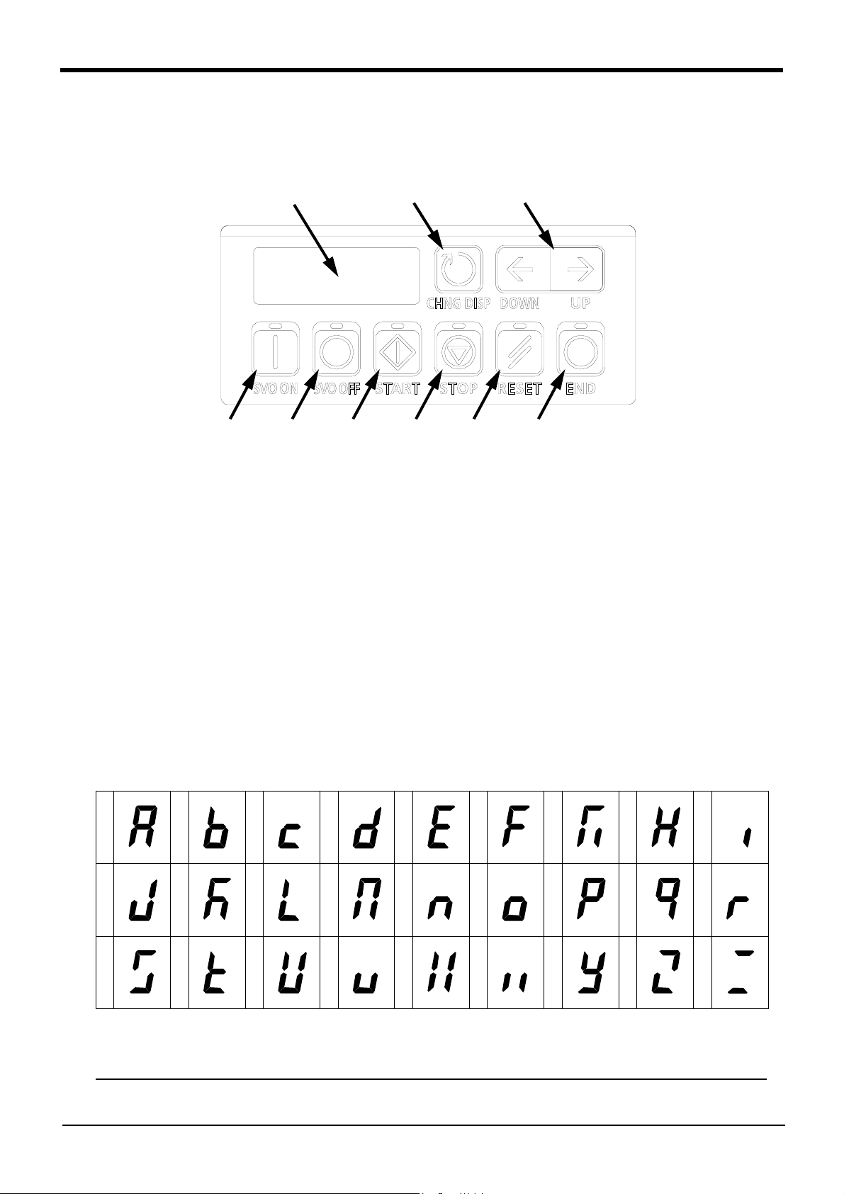
2Explanation of functions
<8>
<4>
<9>
<6> <7> <1> <2> <3> <5>
2 Explanation of functions
2.1 Operation panel (O/P) functions (CR750 controller)
(1) Description of the operation panel button
Fig.2-1:Operation panel
<1> START button..................This executes the program and operates the robot. The program is run contin-
uously.
<2> STOP button ...................This stops the robot immediately. The servo does not turn OFF.
<3> RESET button .................This resets the error. This also resets the program's halted state and resets the
program.
<4> CHNG DISP button .........This changes the details displayed on the display panel in the order of
"Override"→ "Line No."→"Program No." → "User infomation"→ "Maker infomation".
<5> END button .....................This stops the program being executed at the last line or END statement.
<6> SVO.ON button ...............This turns ON the servo power. (The servo turns ON.)
<7> SVO.OFF button ............. This turns OFF the servo power. (The servo turns OFF.)
<8> STATUS NUMBER
(display panel).................The alarm No., program No., override value (%), etc., are displayed.
<9> UP/DOWN button............This scrolls up or down the details displayed on the "STATUS. NUMBER" dis-
play panel.
(2) About the status number display
The following is a description of the simplified symbols shown on the 7-segment LED display when displaying a program name specified with alphabetic characters.
ABCDEFGH I
JKLMNOPQR
STUVWXYZ
The character "P" is fixed at the beginning of the program name display, which means that the number of
characters that can be displayed are four or less. Make sure to use no more than four characters when
entering the program name.
It is not possible to select a program name consisting of more than four characters from the operation panel.
However, it is allowed to create a program name consisting of more than four characters in the case of a
program to be executed as a sub-program by the CALLP instruction of the robot language.
2-6Operation panel (O/P) functions (CR750 controller)
?
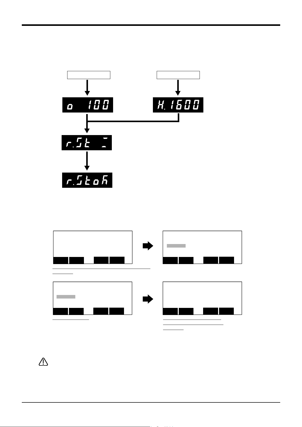
(3) Robot type resetting
<PARAMETER> (MECHRST ) ( )
CLEAR
CLOSE
123
<PARAMETER> NAME(MECHRST )
ELE( )
DATA
( )
CLOSE
123
Next
DATA
Prev
<PARAMETER> NAME(MECHRST )
ELE( )
DATA
( )
CLOSE
123
Next
DATA
Prev
<PARAMETER> NAME(MECHRST )
ELE( )
DATA
( )
CLOSE
123
Next
DATA
Prev
Turn on the power supply with
pushing the [RESET] button.
Continuously, pushing the [RESET] button is continued further.
(About 3 seconds)
The resetting process will be executed, if the [RESET] button is
once released and the [RESET] button is pushed again.
Turn the controller power ON again.
No error
Error occurrence
Robot type can be reset by teaching pendant or RT toolBox2 since controller software version R5q (F-Q series)/S5q
(F-D series).
The method for resetting the robot type by teaching pendant is shown below.
Enter the parameter name [M], [E], [C], [H], [R], [S], [T]
Input [EXE]
Current setting is displayed.
Setting the data [F1] Delete the current data [CLEAR]
Enter the data [C], [L], [E], [A], [R]
Input [EXE]
2) Turn the controller power ON again.
1) Set "CLEAR" to the parameter MECHRST.
CAUTION
If the type information is lost by the ablation of the battery etc., the errors (H1600: Mechanism un-setting. etc.) occur, and the operation becomes impossible.
In this case, it can return to the status at factory shipping by the following type resetting operations.
2Explanation of functions
Because it returns to the status at factory shipping by this operation, so the parameter, the program, and various log data are eliminated.
Therefore, when the error (H1600) has not occurred, don't carry out this operation.
If you have the package backup data (all files) of RT ToolBox/RT ToolBbox 2
(option), it can be restored using the restoration function.
Operation panel (O/P) functions (CR750 controller) 2-7
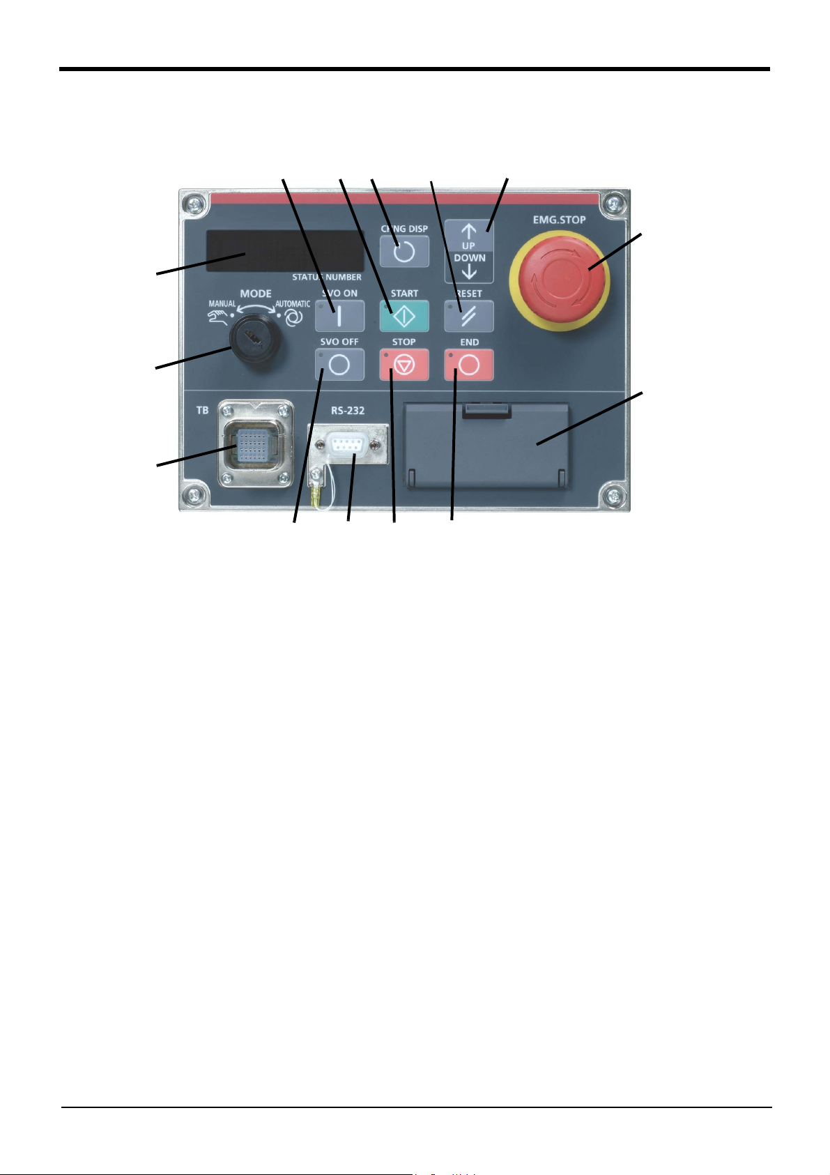
2Explanation of functions
<12>
<1>
<3>
<4>
<5>
<7>
<11>
<10>
<9>
<8>
<13>
<6>
<2><14>
2.2 Operation panel (O/P) functions (CR760 controller)
(1) Description of the operation panel button
Fig.2-2:Operation panel
<1>
START button .......................This executes the program and operates the robot. The program is run continuously.
<2>STOP button .........................This stops the robot immediately. The servo does not turn OFF.
<3>RESET button.......................This resets the error. This also resets the program's halted state and resets the pro-
gram.
<4>Emergency stop switch.........This stops the robot in an emergency state. The servo turns OFF.
<5>CHNGDISP button................This changes the details displayed on the display panel in the order of "Override"→
"Line No."→"Program No." → "User infomation"→ "Maker infomation".
<6>END button ...........................This stops the program being executed at the last line or END statement.
<7>SVO.ON button.....................This turns ON the servo power. (The servo turns ON.)
<8>SVO.OFF button................... This turns OFF the servo power. (The servo turns OFF.)
<9>STATUS NUMBER
(display panel) .......................The alarm No., program No., override value (%), etc., are displayed.
<10>MODE key switch ...............This changes the robot's operation mode.
AUTOMATIC......................operations from the controller or external equipment are valid. Operations for
MANUAL............................When the T/B is valid, only operations from the T/B are valid. Operations for
<11>
UP/DOWN button ...............This scrolls up or down the details displayed on the "STATUS. NUMBER" display panel.
<12>T/B connection connector ..This is a dedicated connector for connecting the T/B. When not using T/B, connect
<13>Interface cover ...............USB interface and battery are mounted. Unused in CR760-Q controller.
<14>RS-232 connector
which the operation mode must be at the external device or T/B are not
possible. It is necessary to set the parameter for the rights of operation to
connection between the operation panel and external equipment. For details,
please refer to Page 11, "2.3.1 Operation rights".
which the operation mode must be at the external device or controller are not
possible.
the attached dummy connector.
...........This is an RS-232 specification connector for connecting the personal computer. Not
installed in the CR760-Q controller.
2-8Operation panel (O/P) functions (CR760 controller)
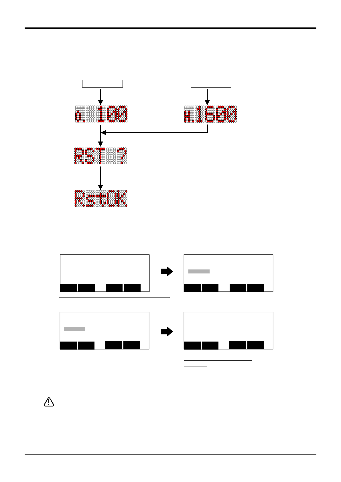
(2) Robot type resetting
[RESET]ボタンを押しながら
電源をONする。
さらに[RESET]ボタンを押し続ける。(約3秒)
[RESET]ボタンを離して、再度[RESET]ボタンを押すと
リセット処理が実行される。
電源リセットされる。
エラー発生時
エラー未発生時
<PARAMETER> (MECHRST ) ( )
CLEAR
CLOSE
123
<PARAMETER> NAME(MECHRST )
ELE( )
DATA
( )
CLOSE
123
Next
DATA
Prev
<PARAMETER> NAME(MECHRST )
ELE( )
DATA
( )
CLOSE
123
Next
DATA
Prev
<PARAMETER> NAME(MECHRST )
ELE( )
DATA
( )
CLOSE
123
Next
DATA
Prev
Robot type can be reset by teaching pendant or RT toolBox2
The method for resetting the robot type by teaching pendant is shown below.
Enter the parameter name [M], [E], [C], [H], [R], [S], [T]
Input [EXE]
Current setting is displayed.
Setting the data [F1] Delete the current data [CLEAR]
Enter the data [C], [L], [E], [A], [R]
Input [EXE]
2) Turn the controller power ON again.
1) Set "CLEAR" to the parameter MECHRST.
No error
Error occurrence
Turn on the power supply with
pushing the [RESET] button.
Continuously, pushing the [RESET] button is continued further.
(About 3 seconds)
The resetting process will be executed, if the [RESET] button is once
released and the [RESET] button is pushed again.
Executes the power resetting.
CAUTION
If the type information is lost by the ablation of the battery etc., the errors (H1600: Mechanism un-setting. etc.) occur, and the operation becomes impossible.
In this case, it can return to the status at factory shipping by the following type resetting operations.
2Explanation of functions
Because it returns to the status at factory shipping by this operation, so the parameter, the program, and various log data are eliminated.
Therefore, when the error (H1600) has not occurred, don't carry out this operation.
If you have the package backup data (all files) of RT ToolBox/RT ToolBbox 2
(option), it can be restored using the restoration function.
Operation panel (O/P) functions (CR760 controller) 2-9
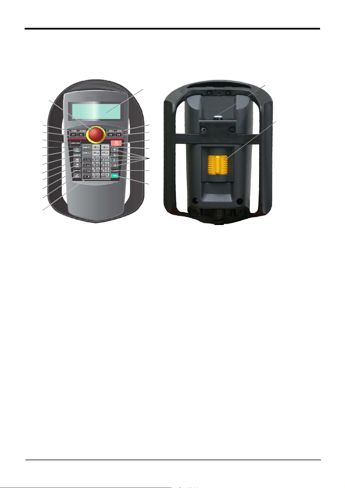
2Explanation of functions
⑪
⑭
⑬
⑫
⑨
⑤
⑥
⑦
⑮
⑯
⑳
⑤
⑥
⑧
⑱
⑲
⑩
⑰
①
④
③
②
1) [EMG. STOP] switch................. The robot servo turns OFF and the operation stops immediately.
2) [Enable/Disable] switch............ This switch changes the T/B key operation between enable and
disable.
3) [Enable] switch......................... When the [Enable/Disable] switch "2)" is enabled, and this key is
released or pressed with force, the servo will turn OFF, and the
operating robot will stop immediately.
4) LCD display panel.................... The robot status and various menus are displayed.
5) Status display lamp.................. Display the state of the robot or T/B.
6) [F1], [F2], [F3], [F4] .................. Execute the function corresponding to each function currently dis-
played on LCD.
7) [FUNCTION]............................. Change the function display of LCD.
8) [STOP] key............................... This stops the program and decelerates the robot to a stop.
9) [OVRD↑][OVRD↓] key .............. Change moving speed. Speed goes up by [OVRD↑] key. Speed
goes down by [OVRD↓] key
10) JOG operation key ................. Move the robot according to jog mode. And, input the numerical
value.
11) [SERVO] key .......................... Press this key with holding [Enable] switch lightly, then servo
power will turn on.
12) [MONITOR] key...................... It becomes monitor mode and display the monitor menu.
13) [JOG] key ............................... It becomes jog mode and display the jog operation.
14) [HAND] key ............................ It becomes hand mode and display the hand operation.
15) [CHAR] key ............................ This changes the edit screen, and changes between numbers and
alphabetic characters.
16) [RESET] key........................... This resets the error. The program reset will execute, if this key
and the EXE key are pressed.
17) [ ↑ ][ ↓ ][←][→] key.................. Moves the cursor each direction.
18) [CLEAR] key........................... Erase the one character on the cursor position.
19) [EXE] key ............................... Input operation is fixed. And, while pressing this key, the robot
moves when direct mode.
20) Number/Character key........... Erase the one character on the cursor position . And, inputs the
number or character
2.3 Teaching pendant (T/B) functions
This chapter explains the functions of R32TB/R33TB (optional).
(1) Function of each key
Fig.2-3:General-view
2-10Teaching pendant (T/B) functions
 Loading...