

Mitsubishi Electric CR750, CR751-D, CR751-Q, CR800, CR751 Instruction Manual

Mitsubishi Industrial Robot
CR800 Series Controller
CR750/CR751 Series Controller
Multifunctional Electric Hand Option
Instruction Manual
BFP-A3408-D

All teaching work must be carried out by an operator who has received special
Always read the following precautions and the separate "Safety
Manual" before starting use of the robot to learn the required
measures to be taken.
Safety Precautions
CAUTION
CAUTION
WARNING
CAUTION
DANGER
CAUTION
CAUTION
CAUTION
training. (This also applies to maintenance work with the power source turned
ON.)
Enforcement of safety training
For teaching work, prepare a work plan related to the methods and procedures
of operating the robot, and to the measures to be taken when an error occurs
or when restarting. Carry out work following this plan. (This also applies to
maintenance work with the power source turned ON.)
Preparation of work plan
Prepare a device that allows operation to be stopped immediately during
teaching work. (This also applies to maintenance work with the power source
turned ON.)
Setting of emergency stop switch
During teaching work, place a sign indicating that teaching work is in progress
on the start switch, etc. (This also applies to maintenance work with the power
source turned ON.)
Indication of teaching work in progress
Provide a fence or enclosure during operation to prevent contact of the
operator and robot.
Installation of safety fence
Establish a set signaling method to the related operators for starting work, and
follow this method.
Signaling of operation start
As a principle turn the power OFF during maintenance work. Place a sign
indicating that maintenance work is in progress on the start switch, etc.
Indication of maintenance work in progress
Before starting work, inspect the robot, emergency stop switch and other
related devices, etc., and confirm that there are no errors.
Inspection before starting work
The points of the precautions given in the separate "Safety Manual" are given below.
DANGER
CAUTION
CAUTION
CAUTION
CAUTION
CAUTION
CAUTION
WARNING
WARNING
CAUTION
WARNING
CAUTION
CAUTION
CAUTION
CAUTION
Refer to the actual "Safety Manual" for details.
When automatic operation of the robot is performed using multiple control
devices (GOT, programmable controller, push-button switch), the interlocking of
operation rights of the devices, etc. must be designed by the customer.
Use the robot within the environment given in the specifications. Failure to do
so could lead to a drop or reliability or faults. (Temperature, humidity,
atmosphere, noise environment, etc.)
Transport the robot with the designated transportation posture. Transporting
the robot in a non-designated posture could lead to personal injuries or faults
from dropping.
Always use the robot installed on a secure table. Use in an instable posture
could lead to positional deviation and vibration.
Wire the cable as far away from noise sources as possible. If placed near a noise
source, positional deviation or malfunction could occur.
Do not apply excessive force on the connector or excessively bend the cable.
Failure to observe this could lead to contact defects or wire breakage.
Make sure that the workpiece weight, including the hand, does not exceed the
rated load or tolerable torque. Exceeding these values could lead to alarms or
faults.
Securely install the hand and tool, and securely grasp the workpiece. Failure to
observe this could lead to personal injuries or damage if the object comes off or
flies off during operation.
Securely ground the robot and controller. Failure to observe this could lead to
malfunctioning by noise or to electric shock accidents.
Indicate the operation state during robot operation. Failure to indicate the state
could lead to operators approaching the robot or to incorrect operation.
When carrying out teaching work in the robot's movement range, always secure
the priority right for the robot control. Failure to observe this could lead to
personal injuries or damage if the robot is started with external commands.
Keep the jog speed as low as possible, and always watch the robot. Failure to do
so could lead to interference with the workpiece or peripheral devices.
After editing the program, always confirm the operation with step operation
before starting automatic operation. Failure to do so could lead to interference
with peripheral devices because of programming mistakes, etc.
Make sure that if the safety fence entrance door is opened during automatic
operation, the door is locked or that the robot will automatically stop. Failure to
do so could lead to personal injuries.
Never carry out modifications based on personal judgments, or use nondesignated maintenance parts.
Failure to observe this could lead to faults or failures.
When the robot arm has to be moved by hand from an external area, do not
WARNING
CAUTION
CAUTION
DANGER
DANGER
DANGER
DANGER
DANGER
CAUTION
place hands or fingers in the openings. Failure to observe this could lead to
hands or fingers catching depending on the posture.
Do not stop the robot or apply emergency stop by turning the robot controller's
main power OFF. If the robot controller main power is turned OFF during
automatic operation, the robot accuracy could be adversely affected. Moreover,
it may interfere with the peripheral device by drop or move by inertia of the arm.
Do not turn off the main power to the robot controller while rewriting the
internal information of the robot controller such as the program or parameters.
If the main power to the robot controller is turned off while in automatic
operation or rewriting the program or parameters, the internal information of the
robot controller may be damaged.
Do not connect the Handy GOT when using the GOT direct connection function
of this product. Failure to observe this may result in property damage or bodily
injury because the Handy GOT can automatically operate the robot regardless
of whether the operation rights are enabled or not.
Do not connect the Handy GOT to a programmable controller when using an iQ
Platform compatible product with the CR7xx-Q/CR800-R/CR800-Q controller.
Failure to observe this may result in property damage or bodily injury because
the Handy GOT can automatically operate the robot regardless of whether the
operation rights are enabled or not.
Do not remove the SSCNET III cable while power is supplied to the multiple
CPU system or the servo amplifier. Do not look directly at light emitted from
the tip of SSCNET III connectors or SSCNET III cables of the Motion CPU or
the servo amplifier. Eye discomfort may be felt if exposed to the light.
(Reference: SSCNET III employs a Class 1 or equivalent light source as
specified in JIS C 6802 and IEC60825-1 (domestic standards in Japan).)
Do not remove the SSCNET III cable while power is supplied to the controller.
Do not look directly at light emitted from the tip of SSCNET III connectors or
SSCNET III cables. Eye discomfort may be felt if exposed to the light.
(Reference: SSCNET III employs a Class 1 or equivalent light source as
specified in JIS C 6802 and IEC60825-1 (domestic standards in Japan).)
Attach the cap to the SSCNET III connector after disconnecting the SSCNET
III cable. If the cap is not attached, dirt or dust may adhere to the connector
pins, resulting in deterioration connector properties, and leading to malfunction.
Make sure there are no mistakes in the wiring. Connecting differently to the way
specified in the manual can result in errors, such as the emergency stop not
being released. In order to prevent errors occurring, please be sure to check
that all functions (such as the teaching box emergency stop, customer emergency stop, and door switch) are working properly after the wiring setup is completed.

Use the network equipments (personal computer, USB hub, LAN hub, etc)
CAUTION
CAUTION
confirmed by manufacturer. The thing unsuitable for the FA environment
(related with conformity, temperature or noise) exists in the equipments
connected to USB. When using network equipment, measures against the noise,
such as measures against EMI and the addition of the ferrite core, may be
necessary. Please fully confirm the operation by customer. Guarantee and
maintenance of the equipment on the market (usual office automation
equipment) cannot be performed.
To maintain the safety of the robot system against unauthorized access from
external devices via the network, take appropriate measures.
To maintain the safety against unauthorized access via the Internet, take measures such as installing a firewall.
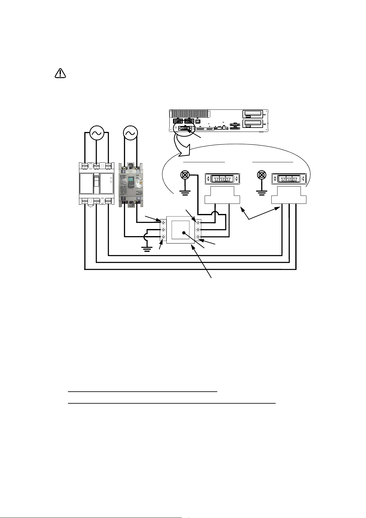
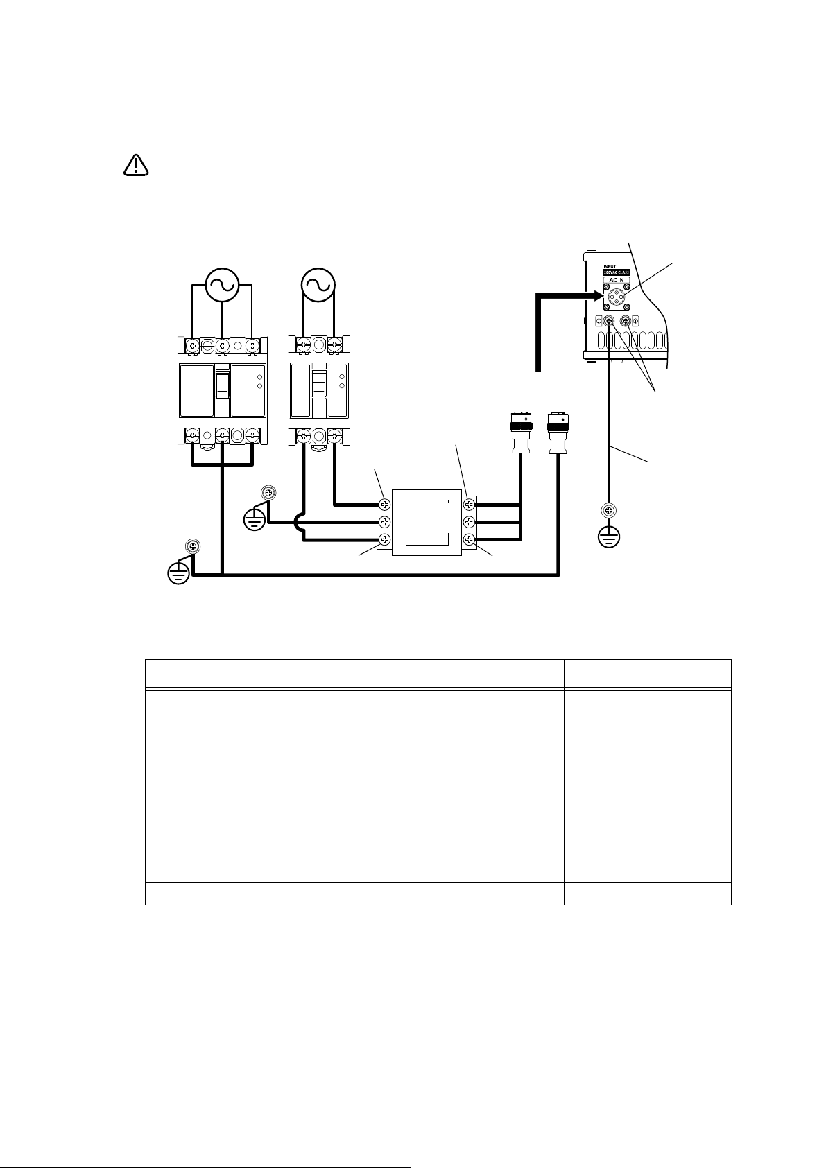
*CR751-D or CR751-Q controller
CAUTION
PE terminal
Grounding screw
Controller
ACIN connector
AC200V AC200V
Primary
Secondary
PE terminal
Grounding screw
123 123
ACIN connector
ACIN connector
Note 2)
Note 1) Crimping swage is recommended for connecting the attachment ACIN connector (soldering is also possible)
Recommendation compression tools: 234171-1(Tyco Electronics)
Note 2) The earth leakage breaker is the customer preparation. Always use the cover below.
Recommendation: For single primary power supply .........NV30FAU-2P-10A-AC100-240V-30mA, (Cover: TCS-05FA2)
For three primary power supply .......... NV30FAU-3P-10A-AC100-240V-30mA, (Cover: TCS-05FA3)
Note 3) If necessary, as shown in the figure, connects the noise filter between ACIN terminal blocks and primary power supply.
(Recommended noise filter: SUP-EL20-ER6 *OKAYA ELECTRIC INDUSTRIES)
Controller
<4> LINE/LOAD
<3> LINE/LOAD
<1> LINE/LOAD
<2> LINE/LOAD
Noise filter
Label
ACIN connector or
power cable
(Attachment)
Note 1)
For three phaseFor single phase
Three phase Single phase
Earth leak-
age breaker
(NV)
Note 3)
* The controller is an
example.
Notes of the basic component are shown.
Please install the earth leakage breaker in the primary side supply power supply
of the controller of CR751-D or CR751-Q because of leakage protection.
1) Please prepare the following: Leakage current breaker (with the terminal cover), cable for connecting the
primary power supply (AWG #14 (2mm
2
(3.5mm
The secondary power cable (with the ACIN connector) for single phase or three phase power is supplied with
the product to match the specifications. When you build a cable suitable for your environment using the ACIN
connector and the ACIN terminal supplied, prepare a secondary power cable (AWG #14 (2mm
2) Confirm that the primary power matches the specifications.
3) Confirm that the primary power is OFF and that the earth leakage breaker power switch is OFF.
4) Connect the secondary power cable.
or above).
a) When using the supplied power cable with the ACIN connector
Refer to the figure above and connect the cable from the secondary side of the earth leakage breaker.
b) When building a power cable using the ACIN connector and the ACIN terminals supplied
Connect the ACIN terminals with the secondary power cable (prepared by customers), and insert the ACIN
terminals to the ACIN connector pins with the following numbers. Crimping caulking is recommended to
connect the ACIN terminals.
For single phase: 1 and 3
For three phase: 1, 2, and 3
Refer to the figure above and connect the cable from the secondary side of the earth leakage breaker.
5) Connect this ACIN connector to the ACIN connector on the front of the controller.
6) Connect the grounding cable to the PE terminal. (M4 screw)
7) Connect the primary power cable to the primary side terminal of the earth leakage breaker.
2
or above), cables to ground the primary power supply (AWG #12
2
) or above).
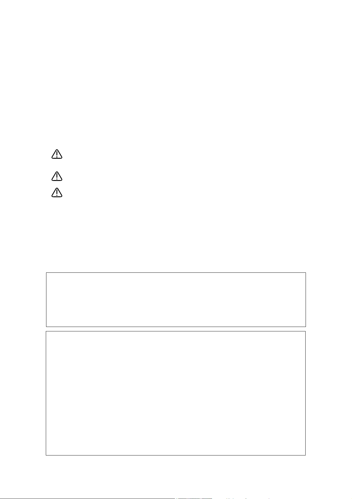
*CR800 controller
CAUTION
㻼㻱㻌㼠㼑㼞㼙㼕㼚㼍㼘
㻼㻱㻌㼠㼑㼞㼙㼕㼚㼍㼘
㻼㼞㼕㼙㼍㼞㼥㻌㼟㼕㼐㼑
㻿㼑㼏㼛㼚㼐㼞㼥㻌㼟㼕㼐㼑
㻿㼕㼚㼓㼘㼑㻌㼜㼔㼍㼟㼑
㻭㻯㻞㻜㻜㼂
㼀㼔㼞㼑㼑㻌㼜㼔㼍㼟㼑
㻭㻯㻞㻜㻜㼂
㻯㼛㼚㼠㼞㼛㼘㼘㼑㼞㻌㼞㼑㼍㼞
㻭㻯㻵㻺㻌㼏㼍㼎㼘㼑
㻔㼍㼠㼠㼍㼏㼔㼙㼑㼚㼠㻕
㻼㻱㻌㼠㼑㼞㼙㼕㼚㼍㼘
㻭㻯㻵㻺㻌㼏㼛㼚㼚㼑㼏㼠㼛㼞
㻳㼞㼛㼡㼚㼐㼕㼚㼓㻌㼏㼍㼎㼘㼑
㻨㻟㻪㻸㻵㻺㻱㻛㻸㻻㻭㻰
㻨㻝㻪㻸㻵㻺㻱㻛㻸㻻㻭㻰
㻨㻠㻪㻸㻵㻺㻱㻛㻸㻻㻭㻰㻨㻞㻪㻸㻵㻺㻱㻛㻸㻻㻭㻰
㻱㼍㼞㼠㼔㻌㼘㼑㼍㼗㼍㼓㼑㻌
㼎㼞㼑㼍㼗㼑㼞㻌㻔㻺㼂㻕
㻸㻝 㻸㻞 㻸㻟
㻸
㻺
㻲㻳
㻼㻱㻌㻔㼜㼞㼛㼠㼑㼏㼠㼕㼢㼑㻌
㼑㼍㼞㼠㼔㻕㻌㼠㼑㼞㼙㼕㼚㼍㼘
㻹㻠㻌㼟㼏㼞㼑㼣
㻺㼛㼕㼟㼑㻌㼒㼕㼘㼠㼑㼞
㻺㼛㼠㼑㻌㻝㻕
Note 1) If necessary, as shown in the figure, connects the noise filter between ACIN connector and primary power supply.
(Recommended noise filter: SUP-EL20-ER6 *OKAYA ELECTRIC INDUSTRIES)
Notes of the basic component are shown.
Please install the earth leakage breaker in the primary side supply power supply
of the controller of CR800 because of leakage protection.
1) Prepare the following items.
Part name Specifications Remarks
Earth leakage breaker The following is recommended product. Prepared by customer.
Single phase: NV30FAU-2P-10A-AC100-240V-30mA
(Terminal cover: TCS-05FA2)
Three phase: NV30FAU-3P-10A-AC100-240V-30mA
(Terminal cover: TCS-05FA3)
Cable for primary power supply
AWG14 (2mm
2
) or above
Grounding cable
ACIN cable Terminal: M5, cable length: 3m Supplied with the product.
AWG14 (2mm
2
) or above
2) Confirm that the primary power matches the specifications.
3) Confirm that the primary power is OFF and that the earth leakage breaker power switch is OFF.
4) Connect the ACIN cable to the breaker.
Connect the power terminals of the ACIN cable to the secondary side terminals of the earth leakage breaker.
Also, ground the FG terminal of the cable.
5) Connect the ACIN cable to the ACIN connector on the rear of the controller.
6) Connect one end of the grounding cable to the PE (protective earth) terminal on the controller and ground the
other end (2-point grounding) in order to comply with the requirements of EN 61800-5-1 for the touch current of 3.5 mA AC or more.
7) Connect the primary power cable to the primary side terminal of the earth leakage breaker.
Prepared by customer.
Tightening torque for terminal
fixing screw is 2 ~ 3Nm.
Prepared by customer.
Tightening torque for terminal
fixing screw is 2 ~ 3Nm.

Revision history
Date Specifications No. Details of revisions
2015-10-05 BFP-A3408 • First print
2015-10-23 BFP-A3408-A • Corrected the errors in the Item column of Table 3-3: hand cable.
2015-11-11 BFP-A3408-B • “Table 2-5: Specifications of the control unit” was deleted.
2017-07-12 BFP-A3408-C • Descriptions about the CR800 controller have been added.
2018-02-01 BFP-A3048-D • Descriptions about the CR800-Q controller have been added.
* Introduction
Danger
Warning
Caution
• No part of this manual may be reproduced by any means or in any form, without prior consent
from Mitsubishi.
• The contents of this manual are subject to change without notice.
• The specifications values are based on Mitsubishi standard testing methods.
• The information contained in this document has been written to be accurate as much as possible. Please interpret that items not described in this document "cannot be performed." or
"alarm may occur".
Please contact your nearest dealer if you find any doubtful, wrong or skipped point.
• This specifications is original.
• All company names and production names in this document are the trademarks or registered
trademarks of their respective owners.
• In the main text, ® and TM marks are omitted.
Copyright(C) 2015-2018 MITSUBISHI ELECTRIC CORPORATION
Notice
*ONLY QUALIFIED SERVICE PERSONNEL MAY INSTALL OR SERVICE THE ROBOT SYSTEM.
*ANY PERSON WHO PROGRAM, TEACHES, OPERATE, MAINTENANCE OR REPAIRS THE ROBOT
SYSTEM IS TRAINED AND DEMONSTRATES COMPETENCE TO SAFELY PERFORM THE ASSIGNED
TASK.
*ENSURE COMPLIANCE WITH ALL LOCAL AND NATIONAL SAFETY AND ELECTRICAL CODES FOR
THE INSTALLATION AND OPERATION OF THE ROBOT SYSTEM.
Thank you for purchasing Mitsubishi Electric industrial robot.
This instruction manual explains “Multifunctional Electric Hand” option.
"Highly precise gripping force" "the location" "speed control" is possible, and this product can apply
it to the various uses.
Always read over this manual to gain a sufficient understanding of its content before using the "Multifunctional Electric Hand".
Please note that this instruction manual assumes that operators have an understanding of basic Mitsubishi Electric industrial robot operation and functionality. Refer to the separate "Instruction Manual, Detailed Explanations of Functions and Operations" for information on basic operation.
* Notation used in this manual
Incorrect handling may result in imminent danger, leading to death or serious injury.
Incorrect handling may lead to death or serious injury.
Incorrect handling may result in property damage, or danger leading to
impairment of the user.

Contents
Page
1 Using This Manual .......................................................................................................................... 1-1
1.1 Content of This Instruction Manual ........................................................................................... 1-1
2 Specifications .................................................................................................................................. 2-2
2.1 What is the Electric Hand? ........................................................................................................ 2-2
2.2 System Configuration ................................................................................................................ 2-2
2.2.1 CR800 Outline .................................................................................................................... 2-2
2.2.2 CR750/CR751 Outline ........................................................................................................ 2-3
2.2.3 Compatible models ............................................................................................................. 2-3
2.2.4 Limitations ........................................................................................................................... 2-4
(1) Available equipment, software version ............................................................................. 2-4
2.3 Control Unit ............................................................................................................................... 2-4
2.3.1 Specifications ...................................................................................................................... 2-4
2.3.2 Outline Drawing .................................................................................................................. 2-5
(1) 4F-MEHCU-01 .................................................................................................................. 2-5
(2) 4F-MEHCU-02 .................................................................................................................. 2-5
2.4 Electric Hand ............................................................................................................................. 2-6
2.4.1 Models of Electric Hand ...................................................................................................... 2-6
2.4.2 Outline Drawing .................................................................................................................. 2-6
(1) Single cam type ................................................................................................................ 2-6
(2) Screw type ........................................................................................................................ 2-8
2.4.3 Installing the Fingers ........................................................................................................... 2-9
(1) Installing dimensions (Single cam type) ........................................................................... 2-9
(2) Installing dimensions (Screw type) ................................................................................. 2-10
2.4.4 Specifications of Electric Hand ......................................................................................... 2-11
(1) Cam type ........................................................................................................................ 2-11
(2) Screw type ...................................................................................................................... 2-12
(3) 3-finger single cam type ................................................................................................. 2-13
2.5 Hand Cable ............................................................................................................................. 2-14
2.5.1 Models of hand cable ........................................................................................................ 2-14
2.5.2 Outline drawing ................................................................................................................. 2-14
(1) 4F-MEHCBL-01 .............................................................................................................. 2-14
(2) 4F-MEHCBL-02 to 05 ..................................................................................................... 2-14
3 Check Before Use ......................................................................................................................... 3-15
3.1 Product Checking .................................................................................................................... 3-15
3.2 Items to be Prepared by Customer ......................................................................................... 3-16
4 Installation ..................................................................................................................................... 4-17
4.1 Installation and Connection ..................................................................................................... 4-17
4.1.1 RV-2F/2FR Series ............................................................................................................ 4-17
4.1.2 RV-4F/7F/13F/20F Series, RV-4FR/7FR/13FR/20FR Series ........................................... 4-18
4.1.3 RH-3FH/6FH/12FH/20FH Series, RH-3FRH/6FRH/12FRH/20FRH Series ...................... 4-20
4.1.4 RH-3FHR-S91 .................................................................................................................. 4-21
4.2 Maintenance and Inspection ................................................................................................... 4-21
4.2.1 Inspection Timings and Items ........................................................................................... 4-21
4.2.2 Procedure for Visual Inspection ........................................................................................ 4-21
4.2.3 Conducting Operation Check ............................................................................................ 4-22
4.2.4 Reapplication of Grease ................................................................................................... 4-22
(1) Applicable Grease .......................................................................................................... 4-22
(2) Applying Grease to the Guide Part ................................................................................. 4-22
(3) Applying Grease to the Ball Screws ............................................................................... 4-23
(4) Applying Grease to the Liner Guide ............................................................................... 4-23
4.2.5 Cleaning Outside of the Gripper ....................................................................................... 4-23
5 Using the Electric Hand (Programming) ....................................................................................... 5-24
i

Contents
Page
5.1 Operating Procedure ............................................................................................................... 5-24
5.1.1 Setting the Parameter ....................................................................................................... 5-24
(1) The Actuator Type Setting .............................................................................................. 5-24
(2) Setting of the Control Parameter .................................................................................... 5-25
5.1.2 Operation of Electric Hand ................................................................................................ 5-27
(1) Changing the Hand Number ........................................................................................... 5-28
(2) Origin Setting .................................................................................................................. 5-28
(3) Hand Opening and Closing ............................................................................................ 5-29
(4) Teaching the Moving Position ........................................................................................ 5-29
(5) Moving to the Taught Position ........................................................................................ 5-31
(6) Grip Action ...................................................................................................................... 5-32
(7) Setting the Moving Speed .............................................................................................. 5-33
(8) Setting the Force (Holding Force) .................................................................................. 5-33
5.1.3 Specification of the Robot Programming Language ......................................................... 5-34
(1) List of Instructions .......................................................................................................... 5-34
(2) Status variable list .......................................................................................................... 5-34
(3) Detailed explanation of command words ....................................................................... 5-35
(4) Explanation of Each Robot Status Variable ................................................................... 5-45
5.1.4 Parameter list .................................................................................................................... 5-50
5.1.5 Error list ............................................................................................................................ 5-52
ii

1Using This Manual
1 Using This Manual
1.1 Content of This Instruction Manual
This manual is divided up in to the following sections, and describes how to use the electric hand.
Table 1-1:Instruction Manual content
Chapter Title Content
1 Using This Manual Describes the makeup of this manual.
2 Specifications Describes the electric hand system specifications.
3 Check Before Use Describes the product configuration and devices to be prepared. Check
4 Installation Describes how to attach the force sensor to the robot. Pay heed to the precau-
5 Using the Electric Hand (Pro-
gramming)
whether all the required products are present, and check the controller, T/B,
and RT-ToolBox2 versions.
tions when installing the electric hand.
Describes how to use (programming method) the electric hand.
Content of This Instruction Manual 1-1
2Specifications
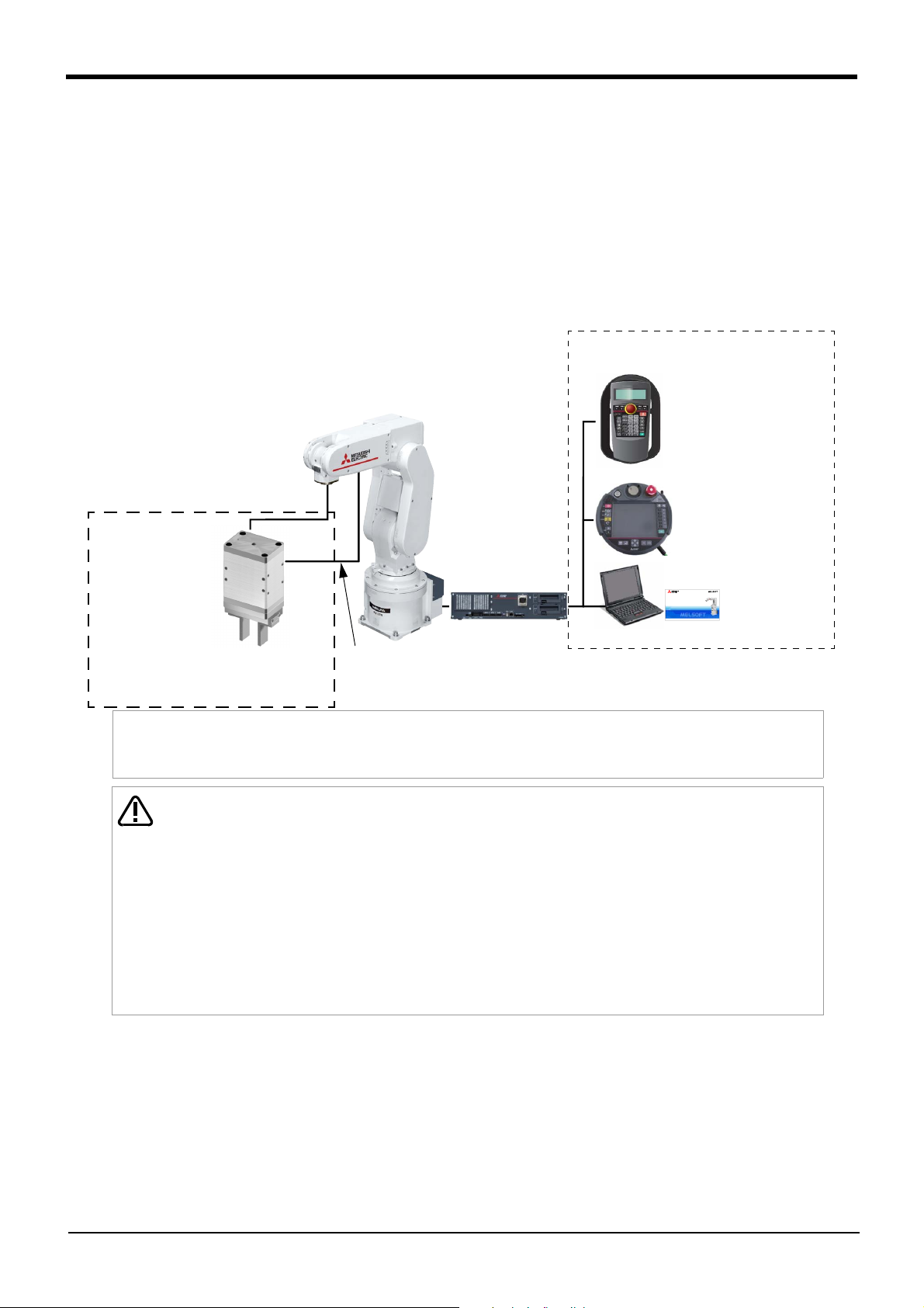
Electric hand (An example)
(selling separately)
Install
Signal cable connection
Robot arm
Note1)
Robot controller
Parameter setup/operation tool (Equipment)
(One of optional equipment is necessary)
R32TB
R56TB
RT ToolBox3
Note1) The figure is the example of constitution of RV-2FR.
Note2) The figure of the electric hand is an example. Refer to the instructions manual attached to the electric hand for attach-
ments and specification, etc. of the electric hand.
When adjusting the electric hand section, you should turn off the drive power
supply of the electric hand sure. Otherwise, there exists the danger that the
hand or the finger will be caught. And, even if the servo of the robot arm turns
off, the electric hand maintains condition of turning ON the drive power supply.This is the measure for not dropping carelessly the work piece which is
doing the grip. Operate safely sure after grasping the drive power supply ON/
OFF condition of the electric hand during the teaching or adjustment operations.
The drive power supply of electric hand can be turned off by operation of T/B.
The drive power supply of electric hand turn on automatically by operation of
the hand open or close etc or execution of the instruction to operate.
CAUTION
Note2)
2 Specifications
2.1 What is the Electric Hand?
This product will do "highly precise gripping force" "location control" "speed control" electrically and answer
to the various uses by the rich function and line-up.
2.2 System Configuration
2.2.1 CR800 Outline
One of the example of equipment constitution is shown below.
Integrated FA Software
Robot Total Engineering Support Software
RT ToolBox3
Fig.2-1:Example of electric hand use constitution
Version 1.00A
©2016 MITSUBISHI ELECTRIC CORPORATION ALL RIGHTS RESERVED
2-2 What is the Electric Hand?
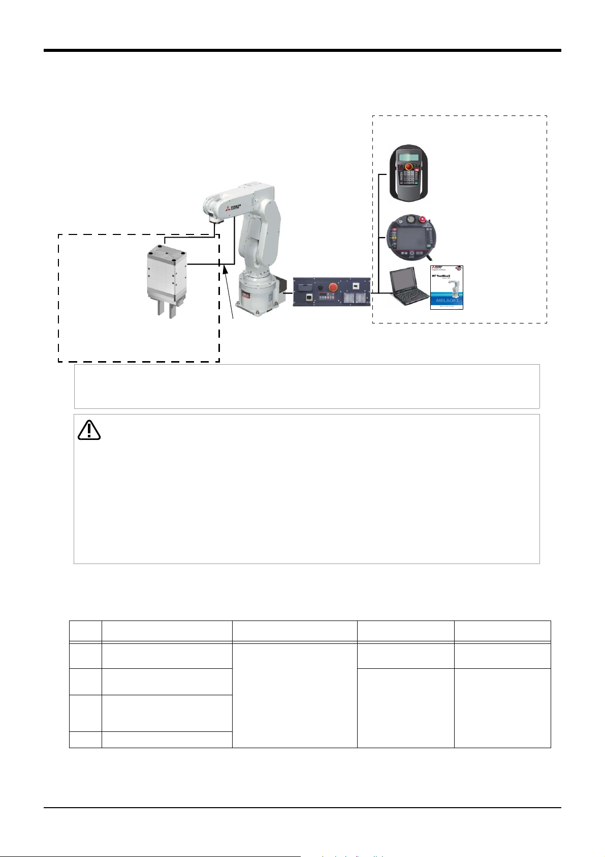
2.2.2 CR750/CR751 Outline
Electric hand (An example)
(selling separately)
Install
Signal cable connection
Robot arm
Note1)
Robot controller
Parameter setup/operation tool (Equipment)
(One of optional equipment is necessary)
R32TB/R33TB
R56TB/R57TB
RT ToolBox2
Note1) The figure is the example of constitution of RV-2F.
Note2) The figure of the electric hand is an example. Refer to the instructions manual attached to the electric hand for attachments
and specification, etc. of the electric hand.
When adjusting the electric hand section, you should turn off the drive power
supply of the electric hand sure. Otherwise, there exists the danger that the
hand or the finger will be caught. And, even if the servo of the robot arm turns
off, the electric hand maintains condition of turning ON the drive power supply.This is the measure for not dropping carelessly the work piece which is
doing the grip. Operate safely sure after grasping the drive power supply ON/
OFF condition of the electric hand during the teaching or adjustment operations.
The drive power supply of electric hand can be turned off by operation of T/B.
The drive power supply of electric hand turn on automatically by operation of
the hand open or close etc or execution of the instruction to operate.
CAUTION
Note2)
One of the example of equipment constitution is shown below.
2Specifications
Fig.2-2:Example of electric hand use constitution
2.2.3 Compatible models
Table 2-1:Compatible models
No. Robot model Electric hand type Control unit Hand cable
1
2 RV-4F/7F/13F/20F series,
3 RH-3FH/6FH/12FH/20FH series,
4 RH-3FHR/3FRHR series
Note1) When using a Multifunctional Electric Hand in iQ Platform compatible type, you can't use an
extended option of a machine cable.
RV-2F/2FR series
RV-4FR/7FR/13FR/20FR series
RH-3FRH/6FRH/12FRH/20FRH
series
Note1)
2-finger single cam type
2-finger screw type
3-finger single cam type
4F-MEHGR-01 to 05
(any one of the electric hands)
4F-MEHCU-01
(Arm mount type)
4F-MEHCU-02
(Floor mount type)
System Configuration 2-3
-
4F-MEHCBL-01 to 05
2Specifications
2.2.4 Limitations
(1) Available equipment, software version
The electric hand can be used with the robot, equipment, tool, and software version shown in Table 2-2.
Table 2-2:Available equipment, software version
Equipment Controller R32TB/R33TB R56TB/R57TB RT ToolBox2 RT ToolBox3
CR751/750
series
CR800 series R type controller: Ver. A1 or later
Q type controller: Ver. R2a or later
D type controller: Ver. S2a or later
D type controller: Ver. A1 or later
Q type controller: Ver. A2 or later
Ver. 1.6 or later Ver. 2.5 or later Ver. 2.3 or later Ver. 1.00A or later
Ver. 1.6 or later Ver. 4.0 or later - Ver. 1.00A or later
2.3 Control Unit
2.3.1 Specifications
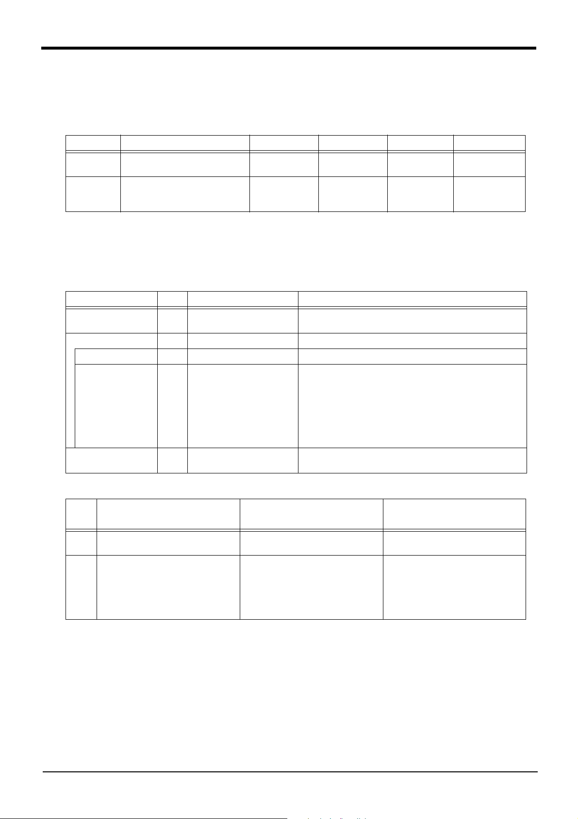
Table 2-3: Specifications of the control unit
Item Unit Specification Remarks
The number of the maximum connection
Connection method - Remote I/O connection
Channel number - Channel 1
Station number
(input-and-output
number)
Teaching point
(maximum)
Unit 1 " Hand 1", " hand 2", " hand 3" is indicated.
- Hand 1: Station number 5
(700 to 731)
Hand 2: Station number 6
(732 to 763)
Hand 3: Station number 7
(764 to 795)
Point 32 The specification value is the maximum teaching point per hand.
Set up the station number with the switch of the electric hand
body.
The hand is distinguishable to the three kinds by setup of the
station number. The one unit of the hand can be used simultaneously.
* The mentioned input-and-output signal is occupied for electric
hands.
They are not useful to the signal output in the user program etc.
Table 2-4:Control unit
No.
1 Arm mount type
(RV-2F/2FR series)
2 Floor mount type
(RV-4F/7F/13F/20F series, RH-3FH/
6FH/12FH/20FH series, RH-3FHR
series, RV-4FR/7FR/13FR/20FR
series, RH-3FRH/6FRH/12FRH/20FRH
series, RH-3FRHR series)
Control unit type
(Compatible robot models)
Model name in TAIYO Model name as our products
ESC11-B-11XW 133-5-M 4F-MEHCU-01
ESC11-B-12XW 111-5-M 4F-MEHCU-02
2-4 Control Unit
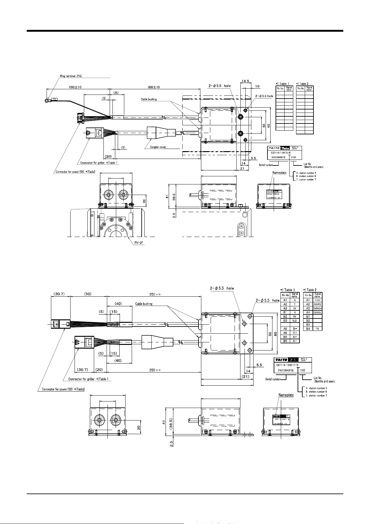
2.3.2 Outline Drawing
665±25
SHINAGAWA SHOKO CO., LTD.
(520166-4)
Misumi (C30-SG9A)
26
FG
5V
B
0V
Z
A
A-
A+
B+
B3
B2
B1
A3
A2
A1
B6
B5
A6
B-A5
-
-
24GRD
+24V
TXRXDL
TXRXDH
-
-
-
-
-
B6
B5
B4
B3
B2
B1
A6
A5
A4
A3
A2
-A1
56
62
62
28
(50)
AMP(1-18127664-6)
J.S.T. Mfg. Co.,Ltd. (R-type 0.5-5)
DDK(DK-2100D-12F)
AMP(2-1318115-4)
DDK(DK-2100D-12F)
83
26
56
62
62
28
Misumi (C30-SG9A)
(1) 4F-MEHCU-01
2Specifications
Fig.2-3:Outline drawing of the control unit (4F-MEHCU-01)
(2) 4F-MEHCU-02
Fig.2-4:Outline drawing of the control unit (4F-MEHCU-02)
Control Unit 2-5
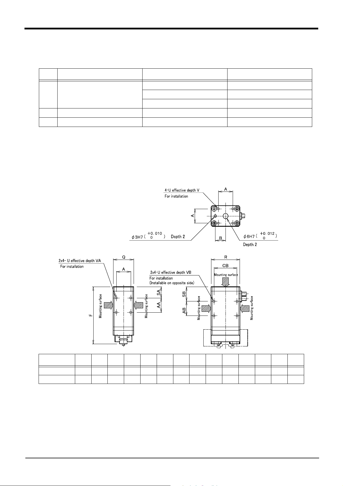
2Specifications
(Unit: mm)
Model
A
AA AB
B
CB
FQR
SA SB
UV
VA VB
ESG1-S*-20**17171712277124341317M3 5 6 6
ESG1-S*-28**24241415387832461621M4 6 8 8
2.4 Electric Hand
2.4.1 Models of Electric Hand
Table 2-5:Electric hand
No. Electric hand type Model name in TAIYO Model name as our products
1 2-finger single cam type ESG1-SS-2005-5N-11XW 107-M 4F-MEHGR-01
ESG1-SS-2010-11XW 107-M 4F-MEHGR-02
ESG1-SS-2815-11XW 107-M 4F-MEHGR-03
2 2-finger screw type ESG1-FT-2840-11XW 109-M 4F-MEHGR-04
3 3-finger single cam type ESG1-ST-2013-11XW 110-M 4F-MEHGR-05
2.4.2 Outline Drawing
(1) Single cam type
ESG1-SS-2005-5N-11XW 107-M (4F-MEHGR-01): Refer to Fig. 2-6.
ESG1-SS-2010-11XW 107-M (4F-MEHGR-02): Refer to Fig. 2-5.
ESG1-SS-2815-11XW 107-M (4F-MEHGR-03): Refer to Fig. 2-5.
ESG1-ST-2013-11XW 110-M (4F-MEHGR-05): Refer to Fig. 2-7.
Fig.2-5:Outline drawing of the control unit (Single cam type 1)
2-6 Electric Hand
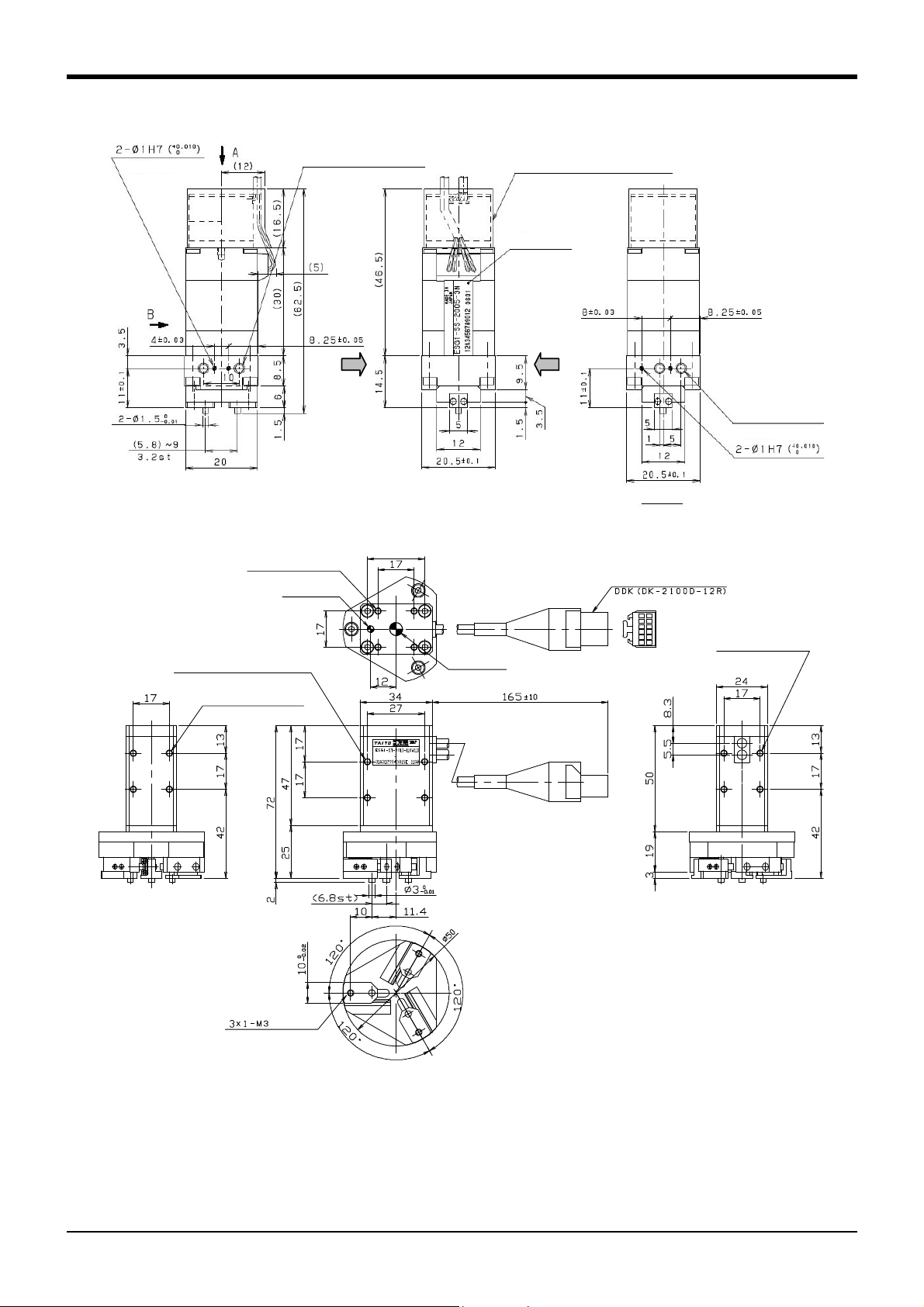
2Specifications
取付面 取付面
Effective depth 1.5
2-M3 effective depth 3
For installation
Cable outlet, Cover for encoder
(Heat shrink tubing)
Nameplate
(Positioning pin)
Mounting
surface
Mounting
surface
2-M3
effective depth 3
For installation
Effective depth 1.5
View B
* This model have only two mounting surface.
4-M3 effective depth 5
4-M3 effective depth 6
Connector
For installation
For installati on
φ3H7 depth 2
φ6H7 depth 2
2x4-M3 effective depth 6
For installation
(Usable on opposite side too)
2x4-M3 effective depth 6
For installati on
For installation of finger
Fig.2-6:Outline drawing of the control unit (Single cam type 2)
Fig.2-7:Outline drawing of the control unit (Single cam type 3)
Electric Hand 2-7
2Specifications
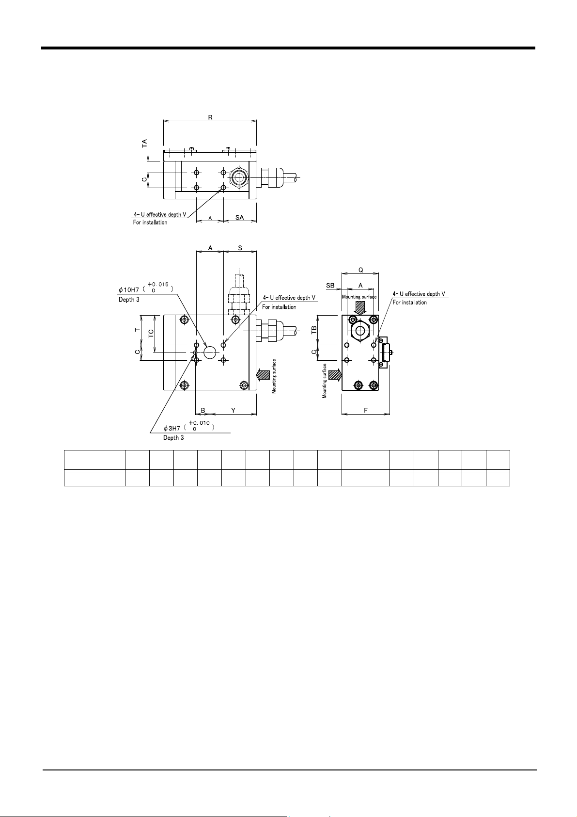
(Unit: mm)
Model A B C F Q R S SA SB T TQ TB TC U V Y
ESG1-FT-28** 30 15 16 52 40 110 40 40 5 28 12 28 36 M5 7.5 55
(2) Screw type
ESG1-FT-2840-11XW 109-M (4F-MEHGR-04): Refer to Fig. 2-8.
Fig.2-8:Outline drawing of the control unit (Screw type)
2-8 Electric Hand
 Loading...