

Mitsubishi Electric CMB-WP1016V-GA1, CMB-WP108V-GA1, CMB-WP108V-GB1, CMB-WP1016V-GB1 Service Manual
Page 1
Page 2
ii
HWE1410A GB
Safety Precautions
Before installing the unit, thoroughly read the following safety precautions.
Observe these safety precautions for your safety.
WARNING
This symbol is intended to alert the user to the presence of important instructions that must be followed to avoid
the risk of serious injury or death.
CAUTION
This symbol is intended to alert the user to the presence of important instructions that must be followed to avoid
the risk of serious injury or damage to the unit.
After reading this manual, give it to the user to retain for future reference.
Keep this manual for easy reference. When the unit is moved or repaired, give this manual to those who provide these
services.
When the user changes, make sure that the new user receives this manual.
WARNING
Do not use refrigerant other than the type indicated in
the manuals provided with the unit and on the nameplate.
Doing so may cause the unit or pipes to burst, or result in
explosion or fire during use, during repair, or at the time of
disposal of the unit.
It may also be in violation of applicable laws.
MITSUBISHI ELECTRIC CORPORATION cannot be held
responsible for malfunctions or accidents resulting from the
use of the wrong type of refrigerant.
Ask your dealer or a qualified technician to install the
unit.
Improper installation by the user may result in water leakage, electric shock, smoke, and/or fire.
Properly install the unit on a surface that can withstand the weight of the unit.
Unit installed on an unstable surface may fall and cause injury.
Only use specified cables. Securely connect each cable so that the terminals do not carry the weight of the
cable.
Improperly connected or fixed cables may produce heat
and start a fire.
Take appropriate safety measures against strong
winds and earthquakes to prevent the unit from falling.
If the unit is not installed properly, the unit may fall and
cause serious injury to the person or damage to the unit.
Do not make any modifications or alterations to the
unit. Consult your dealer for repair.
Improper repair may result in water leakage, electric shock,
smoke, and/or fire.
Do not touch the heat exchanger fins.
The fins are sharp and dangerous.
In the event of a refrigerant leak, thoroughly ventilate
the room.
If refrigerant gas leaks and comes in contact with an open
flame, poisonous gases will be produced.
Properly install the unit according to the instructions
in the installation manual.
Improper installation may result in water leakage, electric
shock, smoke, and/or fire.
Have all electrical work performed by an authorized
electrician according to the local regulations and instructions in this manual, and a dedicated circuit must
be used.
Insufficient capacity of the power supply circuit or improper
installation may result in malfunctions of the unit, electric
shock, smoke, and/or fire.
Page 3
ii
HWE1410A GB
WARNING
Securely attach the terminal block cover (panel) to the
unit.
If the terminal block cover (panel) is not installed properly,
dust and/or water may infiltrate and pose a risk of electric
shock, smoke, and/or fire.
Only use the type of refrigerant that is indicated on the
unit when installing or reinstalling the unit.
Infiltration of any other type of refrigerant or air into the unit
may adversely affect the refrigerant cycle and may cause
the pipes to burst or explode.
When installing the unit in a small room, exercise caution and take measures against leaked refrigerant
reaching the limiting concentration.
Consult your dealer with any questions regarding limiting
concentrations and for precautionary measures before installing the unit. Leaked refrigerant gas exceeding the limiting concentration causes oxygen deficiency.
Consult your dealer or a specialist when moving or reinstalling the unit.
Improper installation may result in water leakage, electric
shock, and/or fire.
After completing the service work, check for a gas
leak.
If leaked refrigerant is exposed to a heat source, such as a
fan heater, stove, or electric grill, poisonous gases may be
produced.
Do not try to defeat the safety features of the unit.
Forced operation of the pressure switch or the temperature
switch by defeating the safety features of these devices, or
the use of accessories other than the ones that are recommended by MITSUBISHI may result in smoke, fire, and/or
explosion.
Only use accessories recommended by MITSUBISHI.
Ask a qualified technician to install the unit. Improper installation by the user may result in water leakage, electric
shock, smoke, and/or fire.
Control box houses high-voltage parts.
When opening or closing the front panel of the control box,
do not let it come into contact with any of the internal components. Before inspecting the inside of the control box,
turn off the power, keep the unit off for at least 10 minutes,
and confirm that the voltage between FT-P and FT-N on
INV Board has dropped to DC20V or less. (It takes about
10 minutes to discharge electricity after the power supply is
turned off.)
Page 4
iiiiii
HWE1410A GB
Precautions for handling units for use with R410A
CAUTION
Do not use the existing refrigerant piping.
A large amount of chlorine that may be contained in the re-
sidual refrigerant and refrigerating machine oil in the existing piping may cause the refrigerating machine oil in the
new unit to deteriorate.
R410A is a high-pressure refrigerant and can cause the
existing pipes to burst.
Use refrigerant pipes made of phosphorus deoxidized
copper. Keep the inner and outer surfaces of the pipes
clean and free of such contaminants as sulfur, oxides,
dust, dirt, shaving particles, oil, and water.
These types of contaminants inside the refrigerant pipes
may cause the refrigerant oil to deteriorate.
Store the pipes to be installed indoors, and keep both
ends of the pipes sealed until immediately before brazing. (Keep elbows and other joints wrapped in plastic.)
Infiltration of dust, dirt, or water into the refrigerant system
may cause the refrigerating machine oil to deteriorate or
cause the unit to malfunction.
Use a small amount of ester oil, ether oil, or alkylbenzene to coat flares and flanges.
Infiltration of a large amount of mineral oil may cause the refrigerating machine oil to deteriorate.
Charge liquid refrigerant (as opposed to gaseous refrigerant) into the system.
If gaseous refrigerant is charged into the system, the composition of the refrigerant in the cylinder will change and
may result in performance loss.
Use a vacuum pump with a reverse-flow check valve.
If a vacuum pump that is not equipped with a reverse-flow
check valve is used, the vacuum pump oil may flow into the
refrigerant cycle and cause the refrigerating machine oil to
deteriorate.
Prepare tools for exclusive use with R410A. Do not use
the following tools if they have been used with the conventional refrigerant (gauge manifold, charging hose,
gas leak detector, reverse-flow check valve, refrigerant
charge base, vacuum gauge, and refrigerant recovery
equipment.).
If the refrigerant or the refrigerating machine oil left on
these tools are mixed in with R410A, it may cause the refrigerating machine oil to deteriorate.
Infiltration of water may cause the refrigerating machine
oil to deteriorate.
Gas leak detectors for conventional refrigerants will not
detect an R410A leak because R410A is free of chlorine.
Do not use a charging cylinder.
If a charging cylinder is used, the composition of the refrigerant will change, and the unit may experience power loss.
Exercise special care when handling the tools for use
with R410A.
Infiltration of dust, dirt, or water into the refrigerant system
may cause the refrigerating machine oil to deteriorate.
Page 5
iv
HWE1410A GB
Before installing the unit
WARNING
Do not install the unit where a gas leak may occur.
If gaseous refrigerant leaks and piles up around the unit, it
may be ignited.
Do not use the unit to keep food items, animals, plants,
artifacts, or for other special purposes.
The unit is not designed to preserve food products.
Do not use the unit in an unusual environment.
Do not install the unit where a large amount of oil or steam
is present or where acidic or alkaline solutions or chemical
sprays are used frequently. Doing so may lead to a remarkable drop in performance, electric shock, malfunctions, smoke, and/or fire.
The presence of organic solvents or corrosive gas (i.e.
ammonia, sulfur compounds, and acid) may cause gas
leakage or water leakage.
When installing the unit in a hospital, take appropriate
measures to reduce noise interference.
High-frequency medical equipment may interfere with the
normal operation of the air conditioner or vice versa.
Do not install the unit on or over things that cannot get
wet.
When the humidity level exceeds 80% or if the drainage
system is clogged, the indoor unit may drip water. Drain water is also discharged from the outdoor unit. Install a centralized drainage system if necessary.
Page 6
vv
HWE1410A GB
Before installing the unit (moving and reinstalling the unit) and performing
electrical work
CAUTION
Properly ground the unit.
Do not connect the grounding wire to a gas pipe, water pipe,
lightning rod, or grounding wire from a telephone pole. Improper grounding may result in electric shock, smoke, fire,
and/or malfunction due to noise interference.
Do not put tension on the power supply wires.
If tension is put on the wires, they may break and result in
excessive heat, smoke, and/or fire.
Install an earth leakage breaker to avoid the risk of
electric shock.
Failure to install an earth leakage breaker may result in
electric shock, smoke, and/or fire.
Use the kind of power supply wires that are specified
in the installation manual.
The use of wrong kind of power supply wires may result in
current leak, electric shock, and/or fire.
Use breakers and fuses (current breaker, remote
switch <switch + Type-B fuse>, moulded case circuit
breaker) with the proper current capacity.
The use of wrong capacity fuses, steel wires, or copper
wires may result in malfunctions, smoke, and/or fire.
Do not spray water on the air conditioner or immerse
the air conditioner in water.
Otherwise, electric shock and/or fire may result.
When handling units, always wear protective gloves to
protect your hands from metal parts and high-temperature parts.
Periodically check the installation base for damage.
If the unit is left on a damaged platform, it may fall and
cause injury.
Properly install the drain pipes according to the instructions in the installation manual. Keep them insulated to avoid dew condensation.
Improper plumbing work may result in water leakage and
damage to the furnishings.
Exercise caution when transporting products.
Products weighing more than 20 kg should not be carried
alone.
Do not carry the product by the PP bands that are used on
some products.
Do not touch the heat exchanger fins. They are sharp and
dangerous.
When lifting the unit with a crane, secure all four corners
to prevent the unit from falling.
Properly dispose of the packing materials.
Nails and wood pieces in the package may pose a risk of
injury.
Plastic bags may pose a risk of choking hazard to chil-
dren. Tear plastic bags into pieces before disposing of
them.
Page 7
vi
HWE1410A GB
Before the test run
CAUTION
Turn on the unit at least 12 hours before the test run.
Keep the unit turned on throughout the season. If the unit is
turned off in the middle of a season, it may result in malfunctions.
To avoid the risk of electric shock or malfunction of the
unit, do not operate switches with wet hands.
Do not touch the refrigerant pipes with bare hands during and immediately after operation.
During or immediately after operation, certain parts of the
unit such as pipes and compressor may be either very cold
or hot, depending on the state of the refrigerant in the unit
at the time. To reduce the risk of frost bites and burns, do
not touch these parts with bare hands.
Do not operate the unit without panels and safety
guards.
Rotating, high-temperature, or high-voltage parts on the unit
pose a risk of burns and/or electric shock.
Do not turn off the power immediately after stopping
the operation.
Keep the unit on for at least five minutes before turning off
the power to prevent water leakage or malfunction.
Do not operate the unit without the air filter.
Dust particles may build up in the system and cause malfunctions.
Use circulation and makeup water that meet the waterquality standards.
Degradation of water quality can result in water leakage.
In areas where temperature drops to freezing during
the periods of non-use, blow the water out of the pipes
or fill the pipes with anti-freeze solution.
Not doing so may cause the water to freeze, resulting in
burst pipes and damage to the unit or the furnishings.
Page 8

CONTENTS
HWE1410A GB
I Read Before Servicing
[1] Read Before Servicing.............................................................................................................. 3
[2] Necessary Tools and Materials ................................................................................................ 4
[3] Piping Materials ........................................................................................................................ 5
[4] Storage of Piping ...................................................................................................................... 7
[5] Pipe Processing........................................................................................................................ 7
[6] Brazing...................................................................................................................................... 8
[7] Air Tightness Test (Refrigerant Circuit) ....................................................................................9
[8] Vacuum Drying (Evacuation) (Refrigerant Circuit).................................................................. 10
[9] Refrigerant Charging .............................................................................................................. 12
[10] Remedies to be taken in case of a Refrigerant Leak............................................................ 12
[11] Characteristics of the Conventional and the New Refrigerants ............................................ 13
[12] Notes on Refrigerating Machine Oil...................................................................................... 14
[13] Water piping.......................................................................................................................... 15
II Restrictions
[1] System configuration .............................................................................................................. 21
[2] Switch Settings and Address Settings .................................................................................... 22
[3] An Example of a System to which an MA Remote Controller is connected ........................... 24
[4] An Example of a System to which an ME Remote Controller is connected ........................... 30
[5] An Example of a System to which both MA Remote Controller and ME Remote
Controller are connected ........................................................................................................32
[6] Restrictions on Pipe Length.................................................................................................... 35
III HBC Controller Components
[1] HBC Controller Components .................................................................................................. 39
[2] Sub-HBC Components ........................................................................................................... 42
[3] Control Box of the HBC Controller and Sub-HBC................................................................... 44
[4] HBC Controller and Sub-HBC Circuit Board........................................................................... 45
IV Electrical Wiring Diagram
[1] Electrical Wiring Diagram of the HBC Controller and Sub-HBC ............................................. 49
[2] Electrical Wiring Diagram of Transmission Booster................................................................ 57
V Refrigerant Circuit
[1] Refrigerant Circuit Diagram .................................................................................................... 61
[2] Principal Parts and Functions ................................................................................................. 64
VI Control
[1] Functions and Factory Settings of the Dipswitches ................................................................ 69
[2] Controlling HBC Controller ..................................................................................................... 70
[3] Operation Flow Chart.............................................................................................................. 79
VII Test Run Mode
[1] Items to be checked before a Test Run.................................................................................. 87
[2] Operating Characteristic and Refrigerant Amount.................................................................. 88
[3] Adjusting the Refrigerant Amount........................................................................................... 88
[4] Refrigerant Amount Adjust Mode............................................................................................ 91
[5] The following symptoms are normal. ...................................................................................... 91
[6] Standard Operation Data (Reference Data) ........................................................................... 92
VIII Troubleshooting
[1] Error Code Lists.................................................................................................................... 111
[2] Responding to Error Display on the Remote Controller........................................................ 115
[3] Investigation of Transmission Wave Shape/Noise ............................................................... 163
[4] Troubleshooting Principal Parts ............................................................................................ 166
[5] Refrigerant Leak ................................................................................................................... 176
[6] Servicing the HBC controller................................................................................................. 178
[7] Instructions for debris removal operation.............................................................................. 180
[8] Instructions for the air vent operation ................................................................................... 181
[9] Instructions for the water pump replacement........................................................................ 182
IX LED Monitor Display on the Outdoor Unit Board
[1] How to Read the LED on the Service Monitor ...................................................................... 201
Page 9

HWE1410A GB
Page 10

- 1 -
HWE1410A GB
I Read Before Servicing
[1] Read Before Servicing ....................................................................................................... 3
[2] Necessary Tools and Materials.......................................................................................... 4
[3] Piping Materials ................................................................................................................. 5
[4] Storage of Piping ............................................................................................................... 7
[5] Pipe Processing................................................................................................................. 7
[6] Brazing............................................................................................................................... 8
[7] Air Tightness Test (Refrigerant Circuit).............................................................................. 9
[8] Vacuum Drying (Evacuation) (Refrigerant Circuit)........................................................... 10
[9] Refrigerant Charging........................................................................................................ 12
[10] Remedies to be taken in case of a Refrigerant Leak .......................................................12
[11] Characteristics of the Conventional and the New Refrigerants ....................................... 13
[12] Notes on Refrigerating Machine Oil ................................................................................. 14
[13] Water piping..................................................................................................................... 15
Page 11

- 2 -
HWE1410A GB
Page 12

[ I Read Before Servicing ]
- 3 -
HWE1410A GB
I Read Before Servicing
[1] Read Before Servicing
1. Check the type of refrigerant used in the system to be serviced.
Refrigerant Type
Multi air conditioner for building application CITY MULTI R2 YLM series: R410A
2. Check the symptoms exhibited by the unit to be serviced.
Refer to this service handbook for symptoms relating to the refrigerant cycle.
3. Thoroughly read the safety precautions at the beginning of this manual.
4. Preparing necessary tools: Prepare a set of tools to be used exclusively with each type of refrigerant.
Refer to "Necessary Tools and Materials" for information on the use of tools.(page 4)
5. Verification of the connecting pipes: Verify the type of refrigerant used for the unit to be moved or replaced.
Use refrigerant pipes made of phosphorus deoxidized copper. Keep the inner and outer surfaces of the pipes clean and free
of such contaminants as sulfur, oxides, dust, dirt, shaving particles, oil, and water.
These types of contaminants inside the refrigerant pipes may cause the refrigerant oil to deteriorate.
6. If there is a leak of gaseous refrigerant and the remaining refrigerant is exposed to an open flame, a poisonous gas
hydrofluoric acid may form. Keep workplace well ventilated.
CAUTION
Install new pipes immediately after removing old ones to keep moisture out of the refrigerant circuit.
The use of refrigerant that contains chloride, such as R22, will cause the refrigerating machine oil to deteriorate.
Page 13
[ I Read Before Servicing ]
- 4 -
HWE1410A GB
[2] Necessary Tools and Materials
Prepare the following tools and materials necessary for installing and servicing the unit.
Tools for use with R410A (Adaptability of tools that are for use with R22 or R407C)
1. To be used exclusively with R410A (not to be used if used with R22 or R407C)
2. Tools and materials that may be used with R410A with some restrictions
3. Tools and materials that are used with R22 or R407C that may also be used with R410A
4. Tools and materials that must not be used with R410A
Tools for R410A must be handled with special care to keep moisture and dust from infiltrating the cycle.
Tools/Materials Use Notes
Gauge Manifold Evacuation and refrigerant charging Higher than 5.09MPa[738psi] on the
high-pressure side
Charging Hose Evacuation and refrigerant charging The hose diameter is larger than the
conventional model.
Refrigerant Recovery Cylinder Refrigerant recovery
Refrigerant Cylinder Refrigerant charging The refrigerant type is indicated. The
cylinder is pink.
Charging Port on the Refrigerant Cylinder Refrigerant charging The charge port diameter is larger
than that of the current port.
Flare Nut Connection of the unit with the pipes Use Type-2 Flare nuts.
Tools/Materials Use Notes
Gas Leak Detector Gas leak detection The ones for use with HFC refrigerant
may be used.
Vacuum Pump Vacuum drying May be used if a check valve adapter
is attached.
Flare Tool Flare processing Flare processing dimensions for the
piping in the system using the new refrigerant differ from those of R22. Refer to I [3] Piping Materials.
Refrigerant Recovery Equipment Refrigerant recovery May be used if compatible with
R410A.
Tools/Materials Use Notes
Vacuum Pump with a Check Valve Vacuum drying
Bender Bending pipes
Torque Wrench Tightening flare nuts Only the flare processing dimensions
for pipes that have a diameter of
ø12.7 (1/2") and ø15.88 (5/8") have
been changed.
Pipe Cutter Cutting pipes
Welder and Nitrogen Cylinder Welding pipes
Refrigerant Charging Meter Refrigerant charging
Vacuum Gauge Vacuum level check
Tools/Materials Use Notes
Charging Cylinder Refrigerant charging Prohibited to use
Page 14
[ I Read Before Servicing ]
- 5 -
HWE1410A GB
[3] Piping Materials
1. Copper pipe materials
The distinction between O-materials (Soft Annealed) and 1/2H-materials (Light Annealed) is made based on the strength of
the pipes themselves.
2. Types of copper pipes
3. Piping materials/Radial thickness
Use refrigerant pipes made of phosphorus deoxidized copper.
The operation pressure of the units that use R410A is higher than that of the units that use R22.
Use pipes that have at least the radial thickness specified in the chart below.
(Pipes with a radial thickness of 0.7 mm or less may not be used.)
For the models for use with R410A, pipes made with O-material (soft annealed) cannot be used unless they have a diameter
of at least ø19.05 (3/4") and a radial thickness of 1.2 t. Use pipes made with 1/2H-material (light annealed).
The figures in the radial thickness column are based on the Japanese standards and provided only as a reference. Use pipes
that meet the local standards.
O-material (Soft Annealed) Soft copper pipes (annealed copper pipes). They can easily be bent with hands.
1/2H-material (Light Annealed) Hard copper pipes (straight pipes). They are stronger than the O-material (Soft An-
nealed) at the same radial thickness.
Maximum working pressure Refrigerant type
3.45 MPa [500psi] R22, R407C etc.
4.30 MPa [624psi] R410A etc.
Pipe size (mm[in]) Radial thickness (mm) Type
ø6.35 [1/4"] 0.8t
O-material (Soft Annealed)
ø9.52 [3/8"] 0.8t
ø12.7 [1/2"] 0.8t
ø15.88 [5/8"] 1.0t
ø19.05 [3/4"] 1.0t
1/2H-material,
H-material
(Light Annealed, Skin Hard)
ø22.2 [7/8"] 1.0t
ø25.4 [1"] 1.0t
ø28.58 [1-1/8"] 1.0t
ø31.75 [1-1/4"] 1.1t
ø34.93 [1-3/8"] 1.2t
ø41.28 [1-5/8"] 1.4t
Do not use the existing piping!
Page 15
[ I Read Before Servicing ]
- 6 -
HWE1410A GB
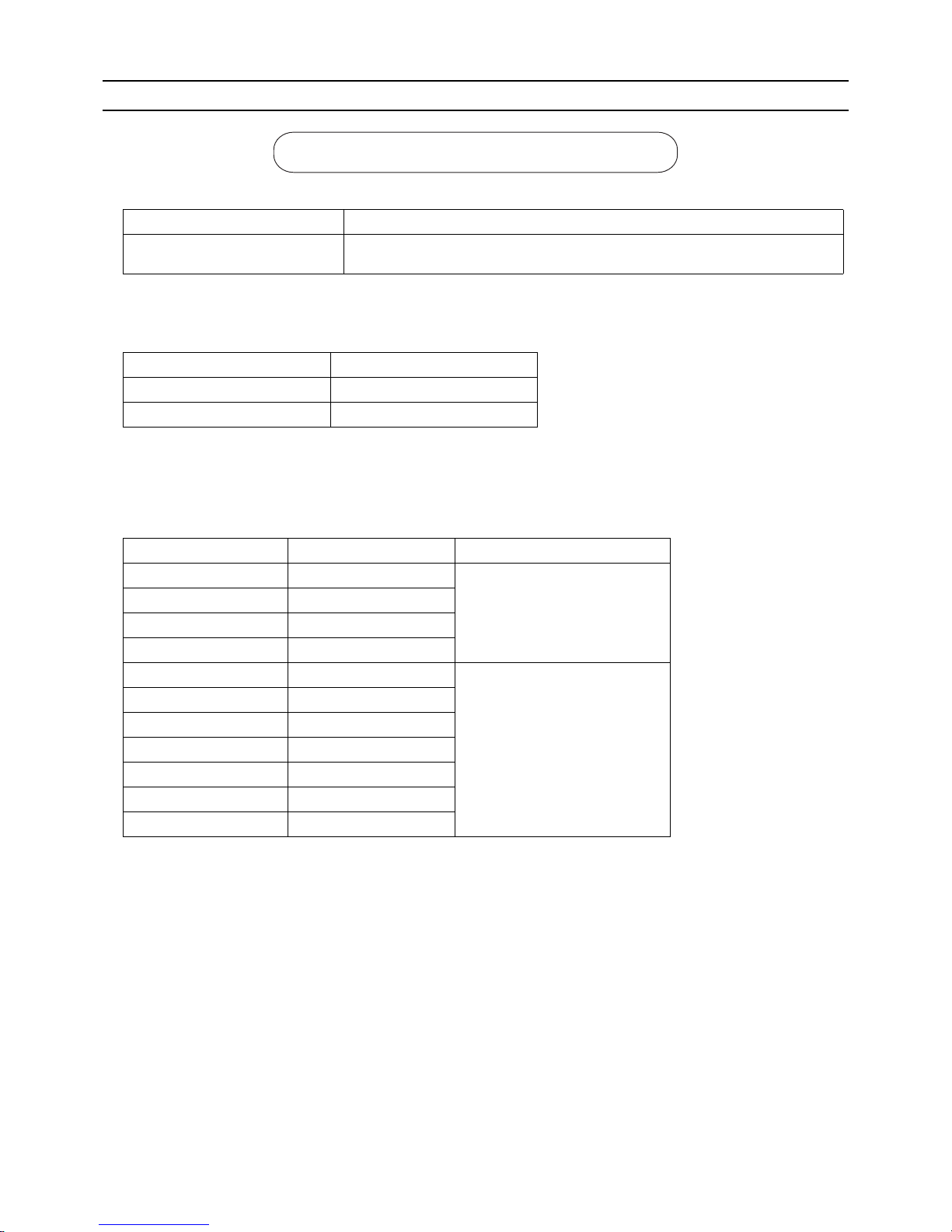
4. Thickness and refrigerant type indicated on the piping materials
Ask the pipe manufacturer for the symbols indicated on the piping material for new refrigerant.
5. Flare processing (O-material (Soft Annealed) and OL-material only)
The flare processing dimensions for the pipes that are used in the R410A system are larger than those in the R22 system.
(ø19.05 pipes should have a radial thickness of 1.2 t and be made of annealed materials.)
If a clutch-type flare tool is used to flare the pipes in the system using R410A, the length of the pipes must be between 1.0
and 1.5 mm. For margin adjustment, a copper pipe gauge is necessary.
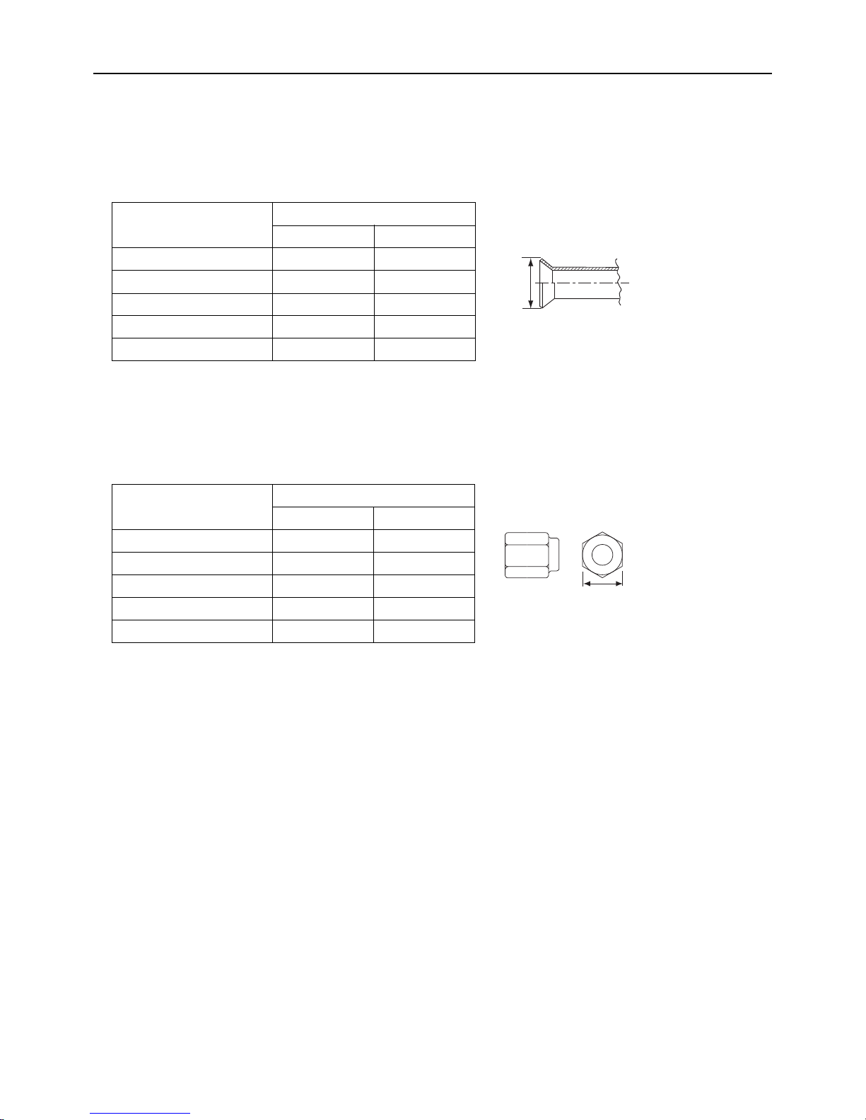
6. Flare nut
The flare nut type has been changed to increase the strength. The size of some of the flare nuts have also been changed.
The figures in the radial thickness column are based on the Japanese standards and provided only as a reference. Use pipes
that meet the local standards.
Flare processing dimensions (mm[in])
Pipe size (mm[in])
A dimension (mm)
R410A R22, R407C
ø6.35 [1/4"] 9.1 9.0
ø9.52 [3/8"] 13.2 13.0
ø12.7 [1/2"] 16.6 16.2
ø15.88 [5/8"] 19.7 19.4
ø19.05 [3/4"] 24.0 23.3
Flare nut dimensions (mm[in])
Pipe size (mm[in])
B dimension (mm)
R410A R22, R407C
ø6.35 [1/4"] 17.0 17.0
ø9.52 [3/8"] 22.0 22.0
ø12.7 [1/2"] 26.0 24.0
ø15.88 [5/8"] 29.0 27.0
ø19.05 [3/4"] 36.0 36.0
Dimension A
Dimension B
Page 16
[ I Read Before Servicing ]
- 7 -
HWE1410A GB
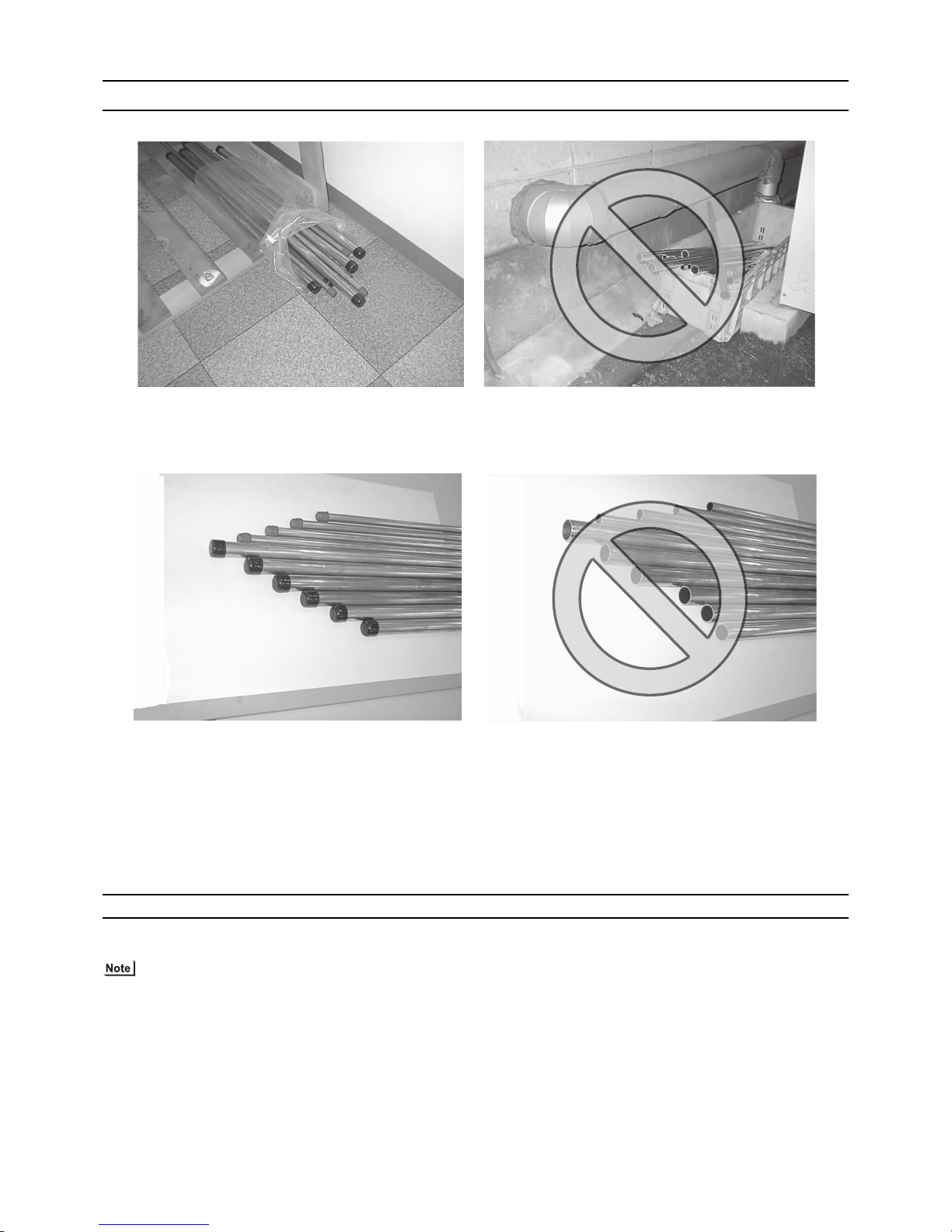
[4] Storage of Piping
1. Storage location
Store the pipes to be used indoors. (Warehouse at site or owner's warehouse)
If they are left outdoors, dust, dirt, or moisture may infiltrate and contaminate the pipe.
2. Sealing the pipe ends
Both ends of the pipes should be sealed until just before brazing.
Keep elbow pipes and T-joints in plastic bags.
The new refrigerator oil is 10 times as hygroscopic as the conventional refrigerating machine oil (such as Suniso) and, if not
handled with care, could easily introduce moisture into the system. Keep moisture out of the pipes, for it will cause the oil to
deteriorate and cause a compressor failure.
[5] Pipe Processing
Use a small amount of ester oil, ether oil, or alkylbenzene to coat flares and flanges.
Use a minimum amount of oil.
Use only ester oil, ether oil, and alkylbenzene.
Page 17
[ I Read Before Servicing ]
- 8 -
HWE1410A GB
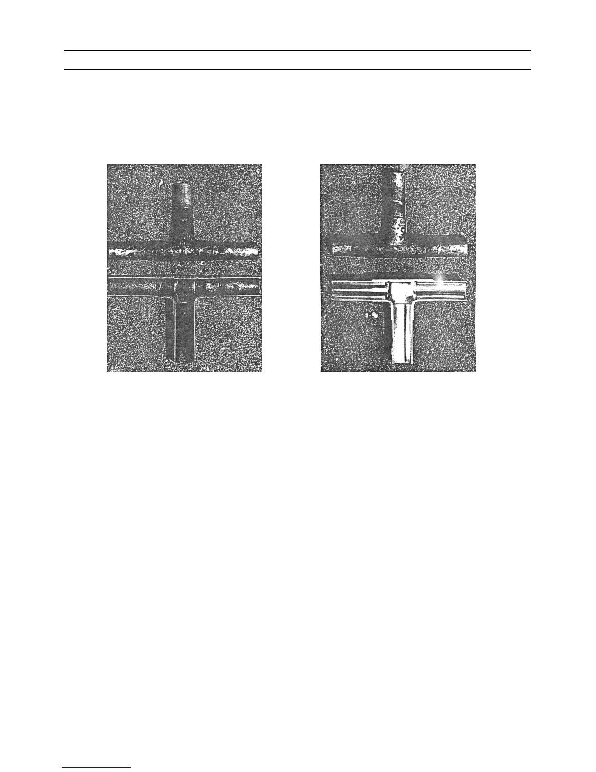
[6] Brazing
No changes have been made in the brazing procedures. Perform brazing with special care to keep foreign objects (such as oxide
scale, water, and dust) out of the refrigerant system.
Example: Inside the brazed connection
1. Items to be strictly observed
Do not conduct refrigerant piping work outdoors if raining.
Use non-oxidized solder.
Use a brazing material (BCuP-3) that requires no flux when brazing between copper pipes or between a copper pipe and
copper coupling.
If installed refrigerant pipes are not immediately connected to the equipment, then braze and seal both ends.
2. Reasons
The new refrigerating machine oil is 10 times as hygroscopic as the conventional oil and is more likely to cause unit failure if
water infiltrates into the system.
Flux generally contains chloride. Residual flux in the refrigerant circuit will cause sludge to form.
3. Notes
Do not use commercially available antioxidants because they may cause the pipes to corrode or refrigerating machine oil to
deteriorate.
Use of oxidized solder for brazing Use of non-oxidized solder for brazing
Page 18

[ I Read Before Servicing ]
- 9 -
HWE1410A GB
[7] Air Tightness Test (Refrigerant Circuit)
No changes have been made in the detection method. Note that a refrigerant leak detector for R22 will not detect an R410A leak.
1. Items to be strictly observed
Pressurize the equipment with nitrogen up to the design pressure (4.15MPa[601psi]), and then judge the equipment's air tight-
ness, taking temperature variations into account.
Refrigerant R410A must be charged in its liquid state (vs. gaseous state).
2. Reasons
Oxygen, if used for an air tightness test, poses a risk of explosion. (Only use nitrogen to check air tightness.)
Refrigerant R410A must be charged in its liquid state. If gaseous refrigerant in the cylinder is drawn out first, the composition
of the remaining refrigerant in the cylinder will change and become unsuitable for use.
3. Notes
Procure a leak detector that is specifically designed to detect an HFC leak. A leak detector for R22 will not detect an
HFC(R410A) leak.
Halide torch R22 leakage detector
Page 19
[ I Read Before Servicing ]
- 10 -
HWE1410A GB
[8] Vacuum Drying (Evacuation) (Refrigerant Circuit)
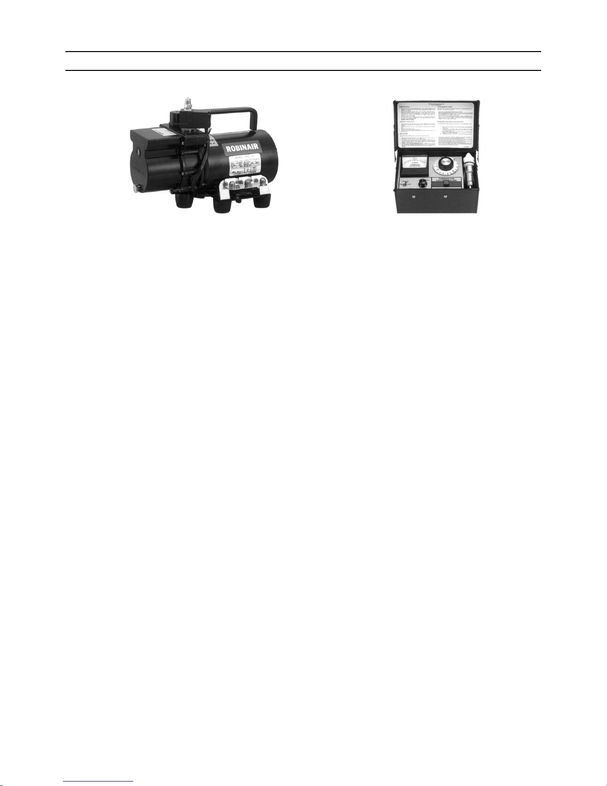
1. Vacuum pump with a reverse-flow check valve (Photo1)
To prevent the vacuum pump oil from flowing into the refrigerant circuit during power OFF or power failure, use a vacuum
pump with a reverse-flow check valve.
A reverse-flow check valve may also be added to the vacuum pump currently in use.
2. Standard of vacuum degree (Photo 2)
Use a vacuum pump that attains 0.5Torr(65Pa) or lower degree of vacuum after 5 minutes of operation, and connect it directly
to the vacuum gauge. Use a pump well-maintained with an appropriate lubricant. A poorly maintained vacuum pump may not
be able to attain the desired degree of vacuum.
3. Required precision of vacuum gauge
Use a vacuum gauge that registers a vacuum degree of 5Torr(650Pa) and measures at intervals of 1Torr(130Pa). (A recommended vacuum gauge is shown in Photo2.)
Do not use a commonly used gauge manifold because it cannot register a vacuum degree of 5Torr(650Pa).
4. Evacuation time
After the degree of vacuum has reached 5Torr(650Pa), evacuate for an additional 1 hour. (A thorough vacuum drying re-
moves moisture in the pipes.)
Verify that the vacuum degree has not risen by more than 1Torr(130Pa) 1hour after evacuation. A rise by less than
1Torr(130Pa) is acceptable.
If the vacuum is lost by more than 1Torr(130Pa), conduct evacuation, following the instructions in section 6. Special vacuum
drying.
5. Procedures for stopping vacuum pump
To prevent the reverse flow of vacuum pump oil, open the relief valve on the vacuum pump side, or draw in air by loosening
the charge hose, and then stop the operation.
The same procedures should be followed when stopping a vacuum pump with a reverse-flow check valve.
6. Special vacuum drying
When 5Torr(650Pa) or lower degree of vacuum cannot be attained after 3 hours of evacuation, it is likely that water has pen-
etrated the system or that there is a leak.
If water infiltrates the system, break the vacuum with nitrogen. Pressurize the system with nitrogen gas to
0.5kgf/cm
2
G(0.05MPa) and evacuate again. Repeat this cycle of pressurizing and evacuation either until the degree of vac-
uum below 5Torr(650Pa) is attained or until the pressure stops rising.
Only use nitrogen gas for vacuum breaking. (The use of oxygen may result in an explosion.)
(Photo1) 15010H (Photo2) 14010
Recommended vacuum gauge:
ROBINAIR 14010 Thermistor Vacuum Gauge
Page 20

[ I Read Before Servicing ]
- 11 -
HWE1410A GB
7. Notes
To evacuate air from the entire system
Applying a vacuum through the check joints at the refrigerant service valve on the high and low pressure sides (BV1
and 2) is not enough to attain the desired vacuum pressure.
Be sure to apply a vacuum through the check joints at the refrigerant service valve on the high and low pressure
sides (BV1 and 2) and also through the check joints on the high and low pressure sides (CJ1 and 2).
To evacuate air only from the outdoor units
Apply a vacuum through the check joints on the high and low pressure sides (CJ1, and 2).
Open the valves in the HBC controller, and switch on the power to the outdoor units, HBC controllers, and indoor
units before performing evacuation so that all refrigerant circuits will be open. (By switching on the power to the indoor units, normal M-NET communication will be maintained.)
Page 21
[ I Read Before Servicing ]
- 12 -
HWE1410A GB
[9] Refrigerant Charging
1. Reasons
R410A is a pseudo-azeotropic HFC blend (boiling point R32=-52°C[-62°F], R125=-49°C[-52°F]) and can almost be handled
the same way as a single refrigerant, such as R22. To be safe, however, draw out the refrigerant from the cylinder in the liquid
phase. If the refrigerant in the gaseous phase is drawn out, the composition of the remaining refrigerant will change and become unsuitable for use.
2. Notes
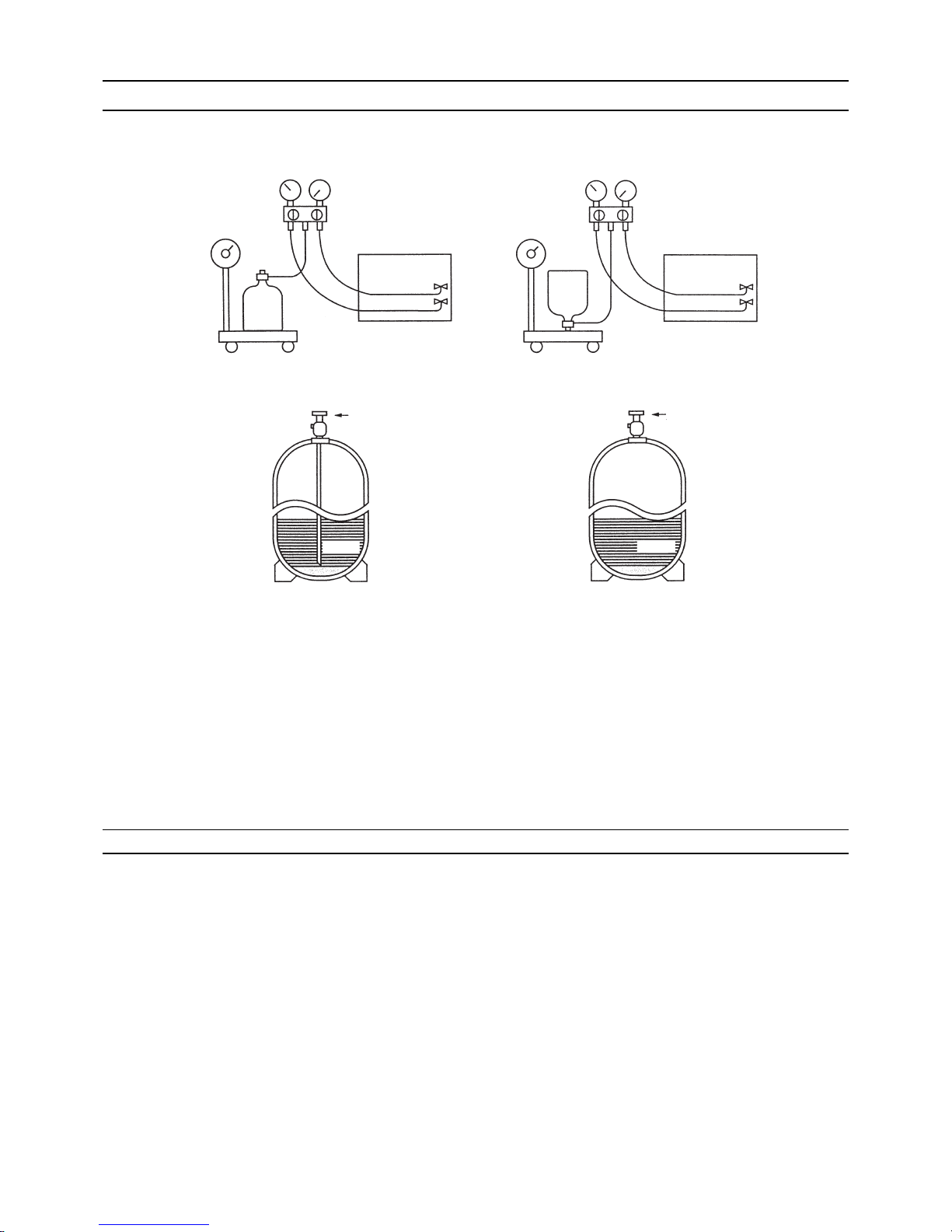
When using a cylinder with a siphon, refrigerant is charged in the liquid state without the need for turning it upside down. Check
the type of the cylinder on the label before use.
[10] Remedies to be taken in case of a Refrigerant Leak
If the refrigerant leaks out, it may be replenished. The entire refrigerant does not need to be replaced. (Charge refrigerant in the
liquid state.)
Refer to "VIII [5] Refrigerant Leak."(page 176)
Cylinder with a siphon
Cylinder color R410A is pink. Refrigerant charging in the liquid state
Cylinder
liquid
Valve Valve
liquid
Cylinder
Cylinder without a siphon
Page 22
[ I Read Before Servicing ]
- 13 -
HWE1410A GB
[11] Characteristics of the Conventional and the New Refrigerants
1. Chemical property
As with R22, the new refrigerant (R410A) is low in toxicity and chemically stable nonflammable refrigerant.
However, because the specific gravity of vapor refrigerant is greater than that of air, leaked refrigerant in a closed room will
accumulate at the bottom of the room and may cause hypoxia.
If exposed to an open flame, refrigerant will generate poisonous gases. Do not perform installation or service work in a confined area.
*1 When CFC11 is used as a reference
*2 When CO
2
is used as a reference
2. Refrigerant composition
R410A is a pseudo-azeotropic HFC blend and can almost be handled the same way as a single refrigerant, such as R22. To
be safe, however, draw out the refrigerant from the cylinder in the liquid phase. If the refrigerant in the gaseous phase is drawn
out, the composition of the remaining refrigerant will change and become unsuitable for use.
If the refrigerant leaks out, it may be replenished. The entire refrigerant does not need to be replaced.
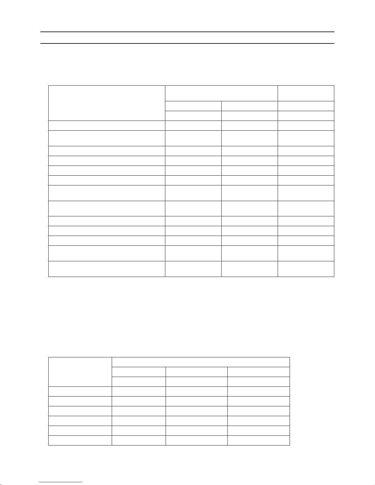
3. Pressure characteristics
The pressure in the system using R410A is 1.6 times as great as that in the system using R22.
New Refrigerant (HFC type) Conventional Refriger-
ant (HCFC type)
R410A R407C R22
R32/R125 R32/R125/R134a R22
Composition (wt%) (50/50) (23/25/52) (100)
Type of Refrigerant Pseudo-azeotropic
Refrigerant
Non-azeotropic
Refrigerant
Single Refrigerant
Chloride Not included Not included Included
Safety Class A1/A1 A1/A1 A1
Molecular Weight 72.6 86.2 86.5
Boiling Point (°C/°F) -51.4/-60.5 -43.6/-46.4 -40.8/-41.4
Steam Pressure
(25°C,MPa/77°F,psi) (gauge)
1.557/226 0.9177/133 0.94/136
Saturated Steam Density
(25°C,kg/m3/77°F,psi)
64.0 42.5 44.4
Flammability Nonflammable Nonflammable Nonflammable
Ozone Depletion Coefficient (ODP)
*1
0 0 0.055
Global Warming Coefficient (GWP)
*2
2090 1774 1810
Refrigerant Charging Method Refrigerant charging in
the liquid state
Refrigerant charging in
the liquid state
Refrigerant charging in
the gaseous state
Replenishment of Refrigerant after a Refrigerant
Leak
Available Available Available
Temperature (°C/°F)
Pressure (gauge)
R410A R407C R22
MPa/psi MPa/psi MPa/psi
-20/-4 0.30/44 0.18/26 0.14/20
0/32 0.70/102 0.47/68 0.40/58
20/68 1.34/194 0.94/136 0.81/117
40/104 2.31/335 1.44/209 1.44/209
60/140 3.73/541 2.44/354 2.33/338
65/149 4.17/605 2.75/399 2.60/377
Page 23
[ I Read Before Servicing ]
- 14 -
HWE1410A GB
[12] Notes on Refrigerating Machine Oil
1. Refrigerating machine oil in the HFC refrigerant system
HFC type refrigerants use a refrigerating machine oil different from that used in the R22 system.
Note that the ester oil used in the system has properties that are different from commercially available ester oil.
2. Effects of contaminants
*1
Refrigerating machine oil used in the HFC system must be handled with special care to keep contaminants out.
The table below shows the effect of contaminants in the refrigerating machine oil on the refrigeration cycle.
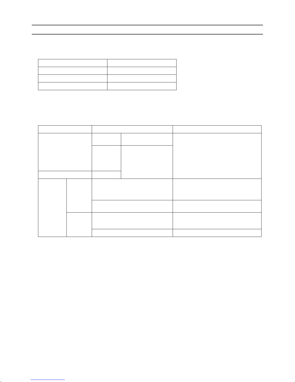
3. The effects of contaminants in the refrigerating machine oil on the refrigeration cycle.
Refrigerant Refrigerating machine oil
R22 Mineral oil
R407C Ester oil
R410A Ester oil
*1. Contaminants is defined as moisture, air, processing oil, dust/dirt, wrong types of refrigerant, and refrigerating machine oil.
Cause Symptoms Effects on the refrigerant cycle
Water infiltration Frozen expansion valve
and capillary tubes
Clogged expansion valve and capillary tubes
Poor cooling performance
Compressor overheat
Motor insulation failure
Burnt motor
Coppering of the orbiting scroll
Lock
Burn-in on the orbiting scroll
Hydrolysis
Sludge formation and adhesion
Acid generation
Oxidization
Oil degradation
Air infiltration Oxidization
Infiltration of
contaminants
Dust, dirt
Adhesion to expansion valve and capillary
tubes
Clogged expansion valve, capillary tubes, and
drier
Poor cooling performance
Compressor overheat
Infiltration of contaminants into the compressor
Burn-in on the orbiting scroll
Mineral oil
etc.
Sludge formation and adhesion Clogged expansion valve and capillary tubes
Poor cooling performance
Compressor overheat
Oil degradation Burn-in on the orbiting scroll
Page 24

[ I Read Before Servicing ]
- 15 -
HWE1410A GB
[13] Water piping
1. Precautions for water piping
Consider the following when installing a water piping system.
(1) Design pressure of the water piping
Use a water pipe that can withstand pressure of at least 1.0 MPa.
(2) Water pipe type
Use of plastic pipe is recommended.Do not use chloride plastic pipes.
When using copper pipes, be sure to braze the pipes under a nitrogen purge. (Oxidation during may shorten the life of the
pump.)
(3) Expansion tank
Install an expansion tank to accommodate expanded water.
(4) Drain piping
Install the drain pipe with a downward inclination of between 1/100 and 1/200. To prevent drain water from freezing in winter,
install the drain pipe as steep an angle as practically possible and minimize the straight line. For cold climate installation, take
an appropriate measure (e.g., drain heater) to prevent the drain water from freezing.
(5) Insulation
Cover the water pipe with insulating materials with the specified thickness or more to prevent thermal loss or condensation
from collecting.
(6) Air vent valve
Install air vent valves to the highest places where air can accumulate.
(7) Maintenance valve
It is recommended to install valves on the inlet/outlet for each HBC controller branch for maintenance.
(8) Water pressure gauge
Install a water pressure gauge to check the charged pressure.
(9) Water pipe connection
When connecting to water pipe, be sure to make the connection in accordance with the relevant local laws and regulations.
Page 25
[ I Read Before Servicing ]
- 16 -
HWE1410A GB
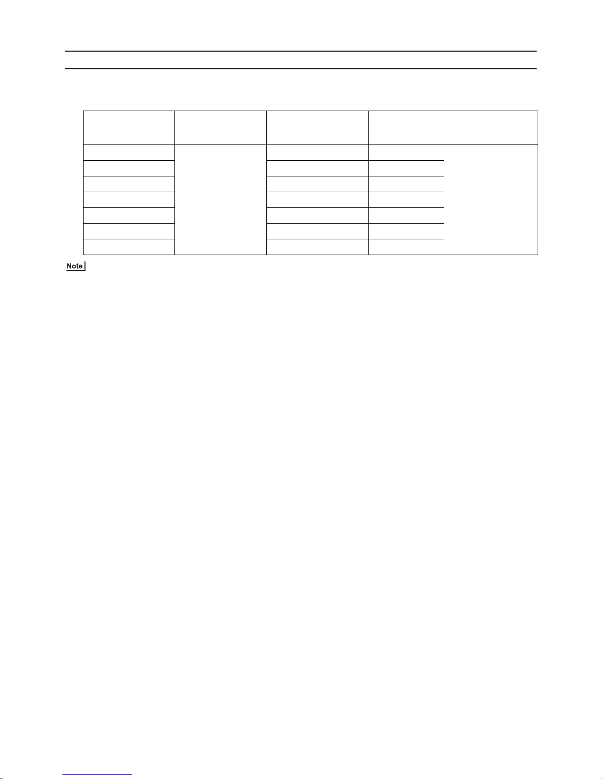
2. Notes on corrosion
(1) Water quality
It is important to check the water quality beforehand. See table below (Circulating water/Makeup Water Quality Standards).
(2) Debris in the water
Sand, pebbles, suspended solids, and corrosion products in water can damage the metal pipe and heat exchanger on the
HBC controller and may cause corrosion. When installing, prevent debris from entering the water. If there is debris in the water, perform debris removal operation after test run by cleaning the strainers inside the HBC controller. (Refer to other sections
for how to perform a test run.)
(3) Connecting pipes made of different materials
Connecting pipes used for HBC controller and indoor unit are copper alloy pipes. If steel pipes are connected tothe pipes, the
contact surface will corrode. Do not use steel pipes to avoid corrosion.
(4) Residual air
Residual air in the pipe results in water pump malfunction, noise, or water pipe corrosion in the water circuit. Ensure air is
purged before use. (Refer to other sections for how to perform air vent operation.)
pH (25°C[77°F])
Electric conductivity
Chloride ion
Sulfate ion
Acid consumption (pH4.8)
Total hardness
Calcium hardness
Ionic silica
Iron
Copper
Sulfide ion
Ammonium ion
Residual chlorine
Free carbon dioxide
Ryzner stability index
Standard items
Reference items
Items
Lower mid-range
temperature water system
7.0 ~ 8.0
30 or less
[300 or less]
50 or less
50 or less
50 or less
70 or less
50 or less
30 or less
1.0 or less
1.0 or less
not to be
detected
0.3 or less
0.25 or less
0.4 or less
–
7.0 ~ 8.0
30 or less
[300 or less]
50 or less
50 or less
50 or less
70 or less
50 or less
30 or less
0.3 or less
0.1 or less
not to be
detected
0.1 or less
0.3 or less
4.0 or less
–
Tendency
Recirculating
water
[68<T<140°F]
[20<T<60°C]
Make-up
water
Corrosive
Scale-
forming
Reference : Guideline of Water Quality for Refrigeration and Air Conditioning
Equipment. (JRA GL02E-1994)
(mg Cl
-
/)
(mg SO
4
2-
/)
(mg CaCO3/)
(mg CaCO3/)
(mg CaCO3/)
(mg SiO2/)
(mg Fe/ )
(mg Cu/ )
(mg S
2-
/)
(mg NH
4
+
/)
(mg Cl/ )
(mg CO2/ )
(mS/m) (25°C[77°F])
(μS/cm) (25°C[77°F])
Page 26
[ I Read Before Servicing ]
- 17 -
HWE1410A GB
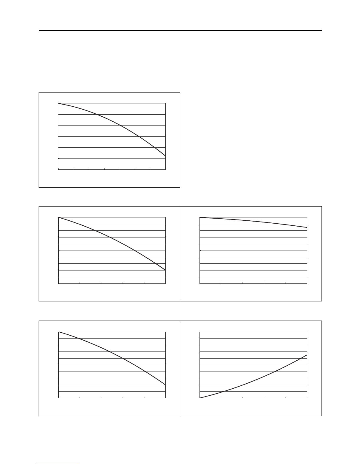
3. Correction by antifreeze-liquid concentration
In HYBRID CITY MULTI system, antifreeze-liquid should be used to prevent the system from freezing. Refer to the following graphs
for the capacity correction by antifreeze-liquid. Refer to (1) for antifreeze-liquid concentration, (2) and (3) for capacity correction by
antifreeze-liquid concentration.
When adding antifreeze-liquid, be sure to perform the process in accordance with the relevant local laws and regulations.
(1) Antifreeze-liquid concentration
Use propylene glycol solution for antifreeze.
Refer to the following graph to estimate the antifreeze-liquid concentration required for freeze protection.
(2) Capacity correction by antifreeze-liquid concentration (cooling)
(3) Capacity correction by antifreeze-liquid concentration (heating)
010203040506070
Freezing Temperature [
°C
]
0
-5
-10
-15
-20
-25
-30
Antifreeze-liquid concentration [wt%]
01020304050
Ratio of cooling capacit y
1
0.99
0.98
0.97
0.96
0.95
0.94
0.93
0.92
0.91
0.9
Antifreeze-liquid concentration [wt%]
PURY-(E)P200~500YLM-A1,PQRY-P200~500YLM-A
01020304050
Ratio of cooling input
1
0.99
0.98
0.97
0.96
0.95
0.94
0.93
0.92
0.91
0.9
Antifreeze-liquid concentration [wt%]
01020304050
Ratio of heating capacity
1
0.99
0.98
0.97
0.96
0.95
0.94
0.93
0.92
0.91
0.9
Antifreeze-liquid concentration [wt%]
PURY-(E)P200~500YLM-A1,PQRY-P200~500YLM-A
01020304050
Ratio of heating input
1.2
1.18
1.16
1.14
1.12
1.1
1.08
1.06
1.04
1.02
1
Antifreeze-liquid concentration [wt%]
Page 27

[ I Read Before Servicing ]
- 18 -
HWE1410A GB
Page 28

- 19 -
HWE1410A GB
II Restrictions
[1] System configuration ....................................................................................................... 21
[2] Switch Settings and Address Settings ............................................................................. 22
[3] An Example of a System to which an MA Remote Controller is connected..................... 24
[4] An Example of a System to which an ME Remote Controller is connected..................... 30
[5] An Example of a System to which both MA Remote Controller and
ME Remote Controller are connected.............................................................................. 32
[6] Restrictions on Pipe Length ............................................................................................. 35
Page 29

- 20 -
HWE1410A GB
Page 30
[ II Restrictions ]
- 21 -
HWE1410A GB
II Restrictions
[1] System configuration
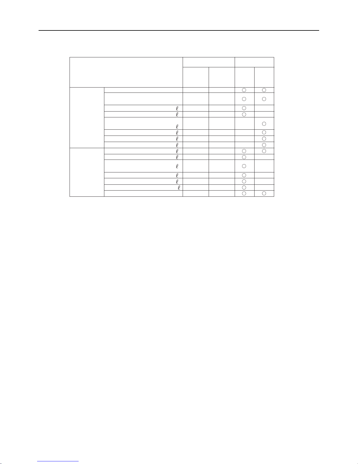
1. Table of compatible indoor units
The table below summarizes the types of indoor units that are compatible with different types of outdoor units.
(1) Standard combinations
1) "Maximum total capacity of connectable indoor units" refers to the sum of the numeric values in the indoor unit model names.
2) If the total capacity of the indoor units that are connected to a given outdoor unit exceeds the capacity of the outdoor unit, the
indoor units will not be able to perform at the rated capacity when they are operated simultaneously. Select a combination of
units so that the total capacity of the connected indoor units is at or below the capacity of the outdoor unit whenever possible.
Outdoor units
(Heat source units)
HBC controller
Sub-HBC
Maximum total capacity
of connectable indoor
units
Maximum number
of connectable in-
door units
Types of connectable
indoor units
(E)P200 CMB-WP108V-GA1,
CMB-WP1016V-GA1
CMB-WP108V-GB1,
CMB-WP1016V-GB1
100 - 300 50 WP15- WP50 models
Indoor units for use with
HBC controller
(E)P250 125 - 375 50
(E)P300 150 - 450 50
(E)P350 175 - 525 50
(E)P400 200 - 600 50
(E)P450 225 - 675 50
(E)P500 250 - 750 50
Page 31

[ II Restrictions ]
- 22 -
HWE1410A GB
[2] Switch Settings and Address Settings
1. Switch setting
Refer to section "[3] An Example of a System to which an MA Remote Controller is connected - [5] An Example of a System
to which both MA Remote Controller and ME Remote Controller are connected" before performing wiring work.
Set the switches while the power is turned off.
If the switch settings are changed while the unit is being powered, those changes will not take effect, and the unit will not
function properly.
*1. Turn off the power to all the outdoor units in the same refrigerant circuit.
Units on which to set the switches Symbol Units to which the power must be shut off
CITY MULTI indoor unit Main/sub unit IC Outdoor units
*1
and Indoor units
ATW Booster Unit BU Outdoor units and Booster Unit
Water Hex Unit AU Outdoor units and Water Hex Unit
ME remote controller Main/sub remote
controller
RC Outdoor units
*1
MA remote controller Main/sub remote
controller
MA Indoor units
CITY MULTI outdoor unit (Heat source unit) OC Outdoor units
*1
HBC controller, Sub-HBC HB, HS Outdoor units
*1
, HBC controller, and Sub-
HBC
Page 32

[ II Restrictions ]
- 23 -
HWE1410A GB
2. M-NET Address settings
(1) Address settings table
The need for address settings and the range of address setting depend on the configuration of the system.
*1. If a given address overlaps any of the addresses that are assigned to other units, use a different, unused address within the setting
range.
*2. To set the outdoor unit address or the auxiliary outdoor unit address to "100," set the rotary switches to "50."
*3. To set the ME remote controller address to "200," set the rotary switches to "00."
*4. Some models of indoor units have two or three control boards.
Assign an address to the No.1, No. 2, and No. 3 control boards so that the No. 2 control board address equals the No. 1 control board
address plus 1, and that the No. 3 control board address equals the No. 1 control board address plus 2.
*5. The outdoor units in the same refrigerant circuit are automatically designated as OC, and OS. They are designated as OC, and OS in
the descending order of capacity (ascending order of address if the capacities are the same).
*6. No address settings are required for units in a system with a single outdoor unit (with some exceptions).
Address setting is required if a sub HBC controller is connected.
*7. If a given address overlaps any of the addresses that are assigned to other units, use a different, unused address within the setting
range.
Unit or controller Sym-
bol
Address
setting
range
Setting method Factory
address
setting
CITY MULTI
indoor unit
Main/sub unit IC 0, 01 to
50
*1 *4 *6*7
Assign the smallest address to the main indoor unit in the
group, and assign sequential address numbers to the rest of
the indoor units in the same group.
00
M-NET
adapter
M-NET control interface
Free Plan
adapter
LOSSNAY, OA processing unit LC 0, 01 to
50
*1 *4 *6*7
Assign an arbitrary but unique address to each of these units
after assigning an address to all indoor units.
00
ATW Booster Unit BU
Water Hex Unit AU
ME remote
controller
Main remote
controller
RC 101 to 150 Add 100 to the smallest address of all the indoor units in the
same group.
101
Sub remote
controller
RC 151 to
200
*3
Add 150 to the smallest address of all the indoor units in the
same group.
MA remote controller MA No address settings required. (The main/sub setting must be made if 2 re-
mote controllers are connected to the system.)
Main
CITY MULTI outdoor unit
(Heat source unit)
OCOS0, 51 to
100
*1 *2
*6*7
Assign an address that equals the lowest address of the in-
door units in the same refrigerant circuit plus 50.
Assign sequential addresses to the outdoor units in the
same refrigerant circuit. The outdoor units in the same refrigerant circuit are automatically designated as OC and
OS.
*5
00
Auxiliary outdoor unit
HBC controller
Sub-HBC
HBHS0, 51 to
100
*1 *2 *6
Assign an address that equals the lowest address of the in-
door units to be connected to the HBC controller or SubHBC plus 50.
If a given address overlaps any of the addresses that are as-
signed to the other units, use a different, unused address
within the setting range.
00
System controller
Group remote controller
GRSC201 to 250 Assign an address that equals the sum of the smallest group
number of the group to be controlled and 200.
201
System remote controller
SR
SC
Assign an arbitrary but unique address within the range listed
on the left to each unit.
ON/OFF remotecontroller
AN
SC
Assign an address that equals the sum of the smallest group
number of the group to be controlled and 200.
Schedule timer (compatible with M-NET)STSC
Assign an arbitrary but unique address within the range listed
on the left to each unit.
202
Central controller
AG-150A
GB-50ADA
G(B)-50A
TRSC0, 201 to
250
Assign an arbitrary but unique address within the range listed
on the left to each unit. The address must be set to "0" to control the K-control unit.
000
LM adapter SC 201 to 250 Assign an arbitrary but unique address within the range listed
on the left to each unit.
247
Page 33

- 24 -
[ II Restrictions ]
GBHWE1410A
[3] An Example of a System to which an MA Remote Controller is connected
1. System with one outdoor unit (Heat source unit) (automatic address setup for both indoor and outdoor units)
(1) Sample control wiring
(2) Cautions
1) ME remote controller and MA remote controller cannot
both be connected to the same group of indoor units.
2) No more than 2 MA remote controllers can be connected
to a group of indoor units.
3) When the number of the connected indoor units is as
shown in the table below, one or more transmission
boosters (sold separately) are required.
To connect two transmission boosters, connect them in
parallel. (Observe the maximum number of connectable
indoor units that are listed in the specifications for each
outdoor unit.)
4) Automatic address setup is not available if start-stop input(CN32, CN51, CN41) is used for a group operation of
indoor units.
5) No more than 2 HBC controllers can be connected.
Sub-HBC cannot be connected.
(3) Maximum allowable length
1) Indoor/outdoor transmission line
Maximum distance (1.25mm
2
[AWG16] or larger)
L1 +L2+L3+L4+L5 200m[656ft]
L1 +L2+L3+L11+L12+L13 200m[656ft]
2) Transmission line for centralized control
No connection is required.
3) MA remote controller wiring
Maximum overall line length
(0.3 to 1.25mm
2
[AWG22 to 16])
m1 200m [656ft]
m2+m3 200m [656ft]
m4+m5 200m [656ft]
IC
TB5
M1
M2
M1
M2
M1
M2
M1
M2
M1
M2
M1
M2
S
TB
15
12
00
IC
TB5STB
15
12
00
A1 B2
MA
A1 B2
MA
A1 B2
RC
LC
TB5
S
00
IC
TB5
S
12
TB
15
IC
TB5STB
15
12
0000
IC
TB5STB
15
12
00
A1 B2
MA
A1 B2
MA
A1 B2
MA
GroupGroup
GroupGroup
A1 B2
MA
m1
L11
m2
L4 L5
L12 L13
m3
m5
m4
Interlock operation with
the ventilation unit
*1. The figures above show a system to which two
outdoor units are connected, but only a single
outdoor unit can be connected in an HVRF
system.
*1
HB
00
OC
00
TB7
M1 M2
S
TB3
OS
00
TB7
M1 M2 M1 M2 M1 M2
S
TB3
TB02
M1 M2
S
L3L1 L2
Leave the male
connector on
CN41 as it is.
SW2-1 OFF
Leave the male
connector on
CN41 as it is.
SW2-1 OFF
Number of transmission
booster (sold separately) required
1 unit 2 units
When the P200 and P250 models are not included in the connected indoor units
27 - 50 units -
When the P200 and P250 models are included in the connected indoor units
21 - 39 units 40 - 50 units
Page 34

[ II Restrictions ]
25- 25 -
HWE1410A GB
(4) Wiring method
1) Indoor/outdoor transmission line
Daisy-chain terminals M1 and M2 of the terminal block
for indoor-outdoor transmission line (TB3) on the outdoor
units (OC and OS), of the terminal block for indoor-outdoor transmission line (TB02) on the HBC controller
(HB), and of the terminal block for indoor-outdoor transmission line (TB5) on each indoor unit (IC). (Non-polarized two-wire)
Only use shielded cables.
The outdoor units in the same refrigerant circuit are automatically designated as OC and OS in the order of capacity from large to small (if two or more units have the
same capacity, in the order of address from small to
large).
Shielded cable connection
Daisy-chain the ground terminal ( ) on the outdoor
units (OC and OS), the S terminal of the terminal block
(TB02) on the HBC controller (HB), and the S terminal of
the terminal block (TB5) on the indoor unit (IC) with the
shield of the shielded cable.
2) Transmission line for centralized control
No connection is required.
3) MA remote controller wiring
Connect terminals 1 and 2 on the terminal block for MA
remote controller line (TB15) on the indoor unit (IC) to the
terminal block on the MA remote controller (MA).
(Non-polarized two-wire)
When 2 remote controllers are connected to the system
When 2 remote controllers are connected to the system,
connect terminals 1 and 2 of the terminal block (TB15) on
the indoor unit (IC) to the terminal block on the two MA
remote controllers.
Set one of the MA remote controllers as a sub controller.
(Refer to the Instruction Manual for the MA remote controller for the setting method.)
Group operation of indoor units
To perform a group operation of indoor units (IC), daisychain terminals 1 and 2 on the terminal block (TB15) on
all indoor units (IC) in the same group, and then connect
terminals 1 and 2 on the terminal block (TB15) on the indoor unit on one end to the terminal block on the MA remotecontroller. (Non-polarized two-wire)
When performing a group operation of indoor units that
have different functions, "Automatic indoor/outdoor addresssetup" is not available.
4) Switch setting
No address settings required.
(5) Address setting method
The outdoor units in the same refrigerant circuit are automatically designated as OC and OS.
They are designated as OC and OS in the descending order of capacity (ascending order of address if the capacities are the
same).
Proce-
dures
Unit or controller
Address set-
ting range
Setting method Notes
Factory
setting
1 Indoor unit Main unit IC No settings
required.
- Port number setting is required
To perform a group operation of indoor units that feature different functions, the
automatic IC/OC address
setup function is not available.
00
Sub unit IC
2 LOSSNAY LC No settings
required.
-00
3MA
remote controller
Main
remote controller
MA No settings
required.
-Main
Sub
remote controller
MA Sub
remote controller
Settings to be
made with the
Sub/Main
switch
4 Outdoor unit
(Heat source unit)
OCOSNo settings
required.
-00
5 Auxiliary
outdoor unit
HBC
controller
HB No settings
required.
-00
Page 35

- 26 -
[ II Restrictions ]
GBHWE1410A
2. A system in which a system controller is connected to the transmission line for centralized control and which is powered from an outdoor unit
(1) Sample control wiring
(2) Cautions
1) ME remote controller and MA remote controller cannot both be connected to the same group of indoor units.
2) No more than 2 MA remote controllers can be connected to a group
of indoor units.
3) Do not connect the terminal blocks (TB5) on the indoor units that are
connected to different outdoor units with each other.
4) Replacement of male power jumper connector (CN41) must be performed only on one of the outdoor units.
(not required if power to the transmission line for centralized control
is supplied from a controller with a power-supply function, such as
GB-50ADA)
5) Short-circuit the shield terminal (S terminal) and the earth terminal (
) on the terminal block for transmission line for centralized control
(TB7) on the outdoor unit whose power jumper connector is mated
with CN40.
6) When the number of the connected indoor units is as shown in the
table below, one or more transmission boosters (sold separately)
are required.
To connect two transmission boosters, connect them in parallel.
(Observe the maximum number of connectable indoor units that are
listed in the specifications for each outdoor unit.)
7) When a power supply unit is connected to the transmission
line for centralized control, leave the power jumper connector on CN41 as it is (factory setting).
(3) Maximum allowable length
1) Indoor/outdoor transmission line
Maximum distance (1.25mm
2
[AWG16] or larger)
L11+L12 200m [656ft]
L21+L22 200m [656ft]
2) Transmission line for centralized control
L31+L32(L21) 200m [656ft]
3) MA remote controller wiring
Same as [3] 1.
4) Maximum line distance via outdoor unit
(1.25mm
2
[AWG16] or larger)
L32+L31+L12(L11) 500m [1640ft]
L32+L22(L21) 500m [1640ft]
L12(L11)+L31+L22(L21) 500m[1640ft]
IC
TB5STB
15
12
01
IC
TB5STB
15
12
02
A1B
2
MA
A1B
2
MA
LC
TB5
S
10
IC
TB5
S
12
TB
15
IC
TB5STB
15
12
0504
LC
TB5
S
09
IC
TB5STB
15
12
07
A1B
2
MA
IC
TB5STB
15
12
08
A1B
2
MA
A1B
2
MA
m3
L31
System controller
ABS
Note1
Note 3
Note 3
L32
OC
To be connected
m2 m1
Note1 When only the LM adapter is connected, leave SW2-1 to OFF (as it is).
Note2 LM adapters require the power supply capacity of single-phase AC 220 - 240V.
Note3 The figures above show a system to which two outdoor units are connected,
but only a single outdoor unit can be connected in an HVRF system.
TB3
TB7
S
51
OS
TB3
TB7
M1 M2 M1 M2
M1 M2
M1 M2
M1 M2
M1 M2
M1 M2 M1M2
M1 M2
M1 M2M1 M2M1 M2
M1 M2
M1 M2
M1 M2M1 M2
M1 M2 M1 M2
S
52
OC
TB3
TB7
S
54
M1 M2
M1 M2
OS
TB3
TB7
S
55
Group
Group
Group
Group Group
Interlock operation with
the ventilation unit
Move the male connector
from CN41 to CN40.
SW2-1 OFF
Leave the male
connector on
CN41 as it is.
SW2-1 OFF
Leave the male
connector on
CN41 as it is.
SW2-1 OFF
Leave the male
connector on
CN41 as it is.
SW2-1 OFF
To be left
unconnected
To be left
unconnected
To be left
unconnected
S
HS
TB02
57
S
HS
TB02
58
S
HB
TB02
53
S
HB
TB02
56
L22
L21
L12
L11
Number of transmission booster
(sold separately) required
1 unit 2 units
When the P200 and P250 models
are not included in the connected
indoor units
27 - 50 units -
When the P200 and P250 models
are included in the connected indoor units
21 - 39 units 40 - 50 units
Page 36

[ II Restrictions ]
27- 27 -
HWE1410A GB
(4) Wiring method
1) Indoor/outdoor transmission line
Daisy-chain terminals M1 and M2 of the terminal block
for indoor-outdoor transmission line (TB3) on the outdoor
units (OC and OS), of the terminal block for indoor-outdoor transmission line (TB02) on the HBC controller
(HB), and of the terminal block for indoor-outdoor transmission line (TB5) on each indoor unit (IC). (Non-polarized two-wire)
Only use shielded cables.
The outdoor units in the same refrigerant circuit are automatically designated as OC and OS in the order of capacity from large to small (if two or more units have the
same capacity, in the order of address from small to
large).
Shielded cable connection
Daisy-chain the ground terminal ( ) on the outdoor
units (OC and OS), the S terminal of the terminal block
(TB02) on HB, and the S terminal of the terminal block
(TB5) on the indoor unit (IC) with the shield of the shielded cable.
2) Transmission line for centralized control
Daisy-chain terminals A and B on the system controller, terminals M1 and M2 on the terminal block for transmission line for
centralized control (TB7) on the outdoor units (OC) in different
refrigerant circuits and on the outdoor units (OC and OS) (Note
a) in the same refrigerant circuit. (Note b)
When both of the following conditions are met, move the power
jumper connector on the control board from CN41 to CN40 on
only one of the outdoor units: (1) No power supply units are connected to the transmission line for centralized control AND (2)
No controllers with a power-supply function are connected to
the system.
If a system controller is connected, set the central control switch
(SW2-1) on the control board of all outdoor units to "ON."
a) The outdoor units in the same refrigerant circuit are automatical-
ly designated as OC and OS in the order of capacity from large
to small (if two or more units have the same capacity, in the order of address from small to large).
b) If TB7's on the outdoor units in the same refrigerant circuit are
not daisy-chained, connect the transmission line for the central
control system to TB7 of the OC. (Note a).To maintain the central control even during an OC failure or a power failure, connect
TB7 on OC and OS together. (If there is a problem with the outdoor unit whose power jumper was moved from CN41 to CN40,
central control is not possible, even if TB7's are daisy-chained.)
Only use shielded cables.
Shielded cable connection
Daisy-chain the S terminal of the terminal block (TB7) on the
system controller, OC, and OS with the shield of the shielded
cable. Short-circuit the earth terminal ( ) and the S terminal
on the terminal block (TB7) on the outdoor unit whose power
jumper connector is mated with CN40.
3) MA remote controller wiring
Same as [3] 1.
When 2 remote controllers are connected to the system
Same as [3] 1.
Group operation of indoor units
Same as [3] 1.
4) LOSSNAY connection
Connect terminals M1 and M2 on the terminal block (TB5) on
the indoor unit (IC) to the appropriate terminals on the terminal
block for indoor-outdoor transmission line (TB5) on LOSSNAY
(LC). (Non-polarized two-wire)
Indoor units must be interlocked with the LOSSNAY unit
using the system controller. (Refer to the operation manual for the system controller for the setting method.) Interlock setting from the remote controller is required if the
ON/OFF remote controller alone or the LM adapter alone
is connected.
(5) Address setting method
The outdoor units in the same refrigerant circuit are automatically designated as OC and OS.
They are designated as OC and OS in the descending order of capacity (ascending order of address if the capacities are the same).
Proce-
dures
Unit or controller
Ad-
dress
setting
range
Setting method Notes
Fac-
tory
set-
ting
1 Indoor
unit
Main unit IC 01 to
50
Assign the smallest address to the mai n unit
in the group.
Port number setting is
required
To perform a group op-
eration of indoor units
that feature different
functions, designate
the indoor unit in the
group with the greatest
number of functions as
the main unit.
00
Sub unit
Assign sequential numbers starting with the
address of the main unit in the same group
+1. (Main unit address +1, main unit address
+2, main unit address +3, etc.)
2 LOSSNAY LC 01 to
50
Assign an arbitrary but unique address to
each of these units after assigning an address
to all indoor units.
None of these addresses may
overlap any of the indoor unit
addresses.
00
3MA
remote
controller
Main
remote controller
MA
No settings required.
-
Make the same indoor unit
group settings with the system
controller as the ones that
were made with the MA remote
controller.
Main
Sub
remote controller
MA
Sub
remote
controller
Settings to be made with the Sub/
Main switch
4 Outdoor unit (Note)
(Heat source unit) OCOS
51 to 100 Assign sequential address to the outdoor
units in the same refrigerant circuit.
The outdoor units are automatically desig-
nated as OC and OS.(Note)
To set the address to 100,
set the rotary switches to 50.
If the address that is as-
signed to the HBC controller
and Sub-HBC overlaps any
of the addresses that are assigned to the other units,
use a different, unused address within the setting
range.
00
5 Auxiliary
outdoor
unit
HBC controller
Sub-HBC
HB
HS
51 to 100 Assign an address that equals the lowest ad-
dress of the indoor units to be connected to
the HBC controller or Sub-HBC plus 50.
Page 37

- 28 -
[ II Restrictions ]
GBHWE1410A
3. An example of a system in which a system controller is connected to the indoor-outdoor transmission line (except
LM adapter)
(1) Sample control wiring
(2) Cautions
1) ME remote controller and MA remote controller cannot both be connected to the same group of indoor units.
2) No more than 2 MA remote controllers can be connected to a group
of indoor units.
3) Do not connect the terminal blocks (TB5) on the indoor units that are
connected to different outdoor units with each other.
4) Replacement of male power jumper connector (CN41) must be performed only on one of the outdoor units.
(not required if power to the transmission line for centralized control
is supplied from a controller with a power-supply function, such as
GB-50ADA)
5) Provide grounding to S terminal on the terminal block for transmission line for centralized control (TB7) on only one of the outdoor
units.
6) A maximum of 3 system controllers can be connected to the indooroutdoor transmission line, with the exception that only one G(B)-50A
may be connected.
7) When the total number of indoor units exceeds 20 (12 if one or more
indoor units of the 200 model or above is connected), it may not be
possible to connect a system controller to the indoor-outdoor transmission line.
8) When the number of the connected indoor units is as shown in the
table below, one or more transmission boosters (sold separately)
are required.
To connect two transmission boosters, connect them in parallel.
(Observe the maximum number of connectable indoor units that are
listed in the specifications for each outdoor unit.)
(3) Maximum allowable length
1) Indoor/outdoor transmission line
Maximum distance (1.25mm
2
[AWG16] or larger)
L11+L12 200m [656ft]
L21+L22 200m [656ft]
L25 200m [656ft]
2) Transmission line for centralized control
L31+L21 200m [656ft]
3) MA remote controller wiring
Same as [3] 1.
4) Maximum line distance via outdoor unit
(1.25mm
2
[AWG16] or larger)
L25+L31+L12(L11) 500m [1640ft]
L12(L11)+L31+L22(L21) 500m [1640ft]
IC
TB5STB
15
12
01
IC
TB5STB
15
12
02
A1B
2
MA
A1B
2
MA
LC
TB5
S
10
IC
TB5
S
12
TB
15
IC
TB5STB
15
12
0504
LC
TB5
S
09
IC
TB5STB
15
12
07
A1B
2
MA
IC
TB5STB
15
12
08
A1B
2
MA
A1B
2
MA
GroupGroupGroup
Group Group
m3
Interlock operation with
the ventilation unit
OC
Connect
m2 m1
Note1 LM adapters cannot be connected to the indoor-outdoor transmission line.
Note2 The figures above show a system to which two outdoor units are connected,
but only a single outdoor unit can be connected in an HVRF system.
TB3
TB7
S
51
OS
TB3
TB7
S
52
OC
TB3
TB7
S
54
OS
TB3
TB7
S
55
L31
M2M1 M2M1
M2M1
M2M1
M2M1
M2M1 M2M1
M2M1 M2M1
M2M1
M2M1
M2M1M2M1
M2M1
M2M1
M2M1
M2M1
M2M1
M2M1
M2M1
Not
Connect
Not
Connect
Not
Connect
CN41 CN40 Replace
SW2-1 OFF ON
SW2-1 OFF ON
Leave the male
connector on
CN41 as it is.
SW2-1 OFF ON
Leave the male
connector on
CN41 as it is.
SW2-1 OFF ON
Leave the male
connector on
CN41 as it is.
ABS
L25
System controller
Note1
Note2
Note2
S
HS
TB02
57
S
HS
TB02
58
S
HB
TB02
53
S
HB
TB02
56
L22
L21
L12
L11
Number of transmission
booster (sold separately)
required
1 unit 2 units
When the P200 and P250 models are not
included in the connected indoor units
27 - 50
units
-
When the P200 and P250 models are included in the connected indoor units
21 - 39
units
40 - 50
units
Page 38

[ II Restrictions ]
29- 29 -
HWE1410A GB
(4) Wiring method
1) Indoor/outdoor transmission line
Daisy-chain terminals M1 and M2 of the terminal block for indooroutdoor transmission line (TB3) on the outdoor units (OC and OS)
(Note a), of the terminal block for indoor-outdoor transmission line
(TB02) on the main and sub BC controllers (BC and BS), of the terminal block for indoor-outdoor transmission line (TB5) on each indoor unit (IC), and the S terminal of the system controller.(Nonpolarized two-wire)
Only use shielded cables.
a) The outdoor units in the same refrigerant circuit are automatically
designated as OC and OS in the order of capacity from large to small
(if two or more units have the same capacity, in the order of address
from small to large).
Shielded cable connection
Daisy-chain the ground terminal ( ) on the outdoor units (OC and
OS), the S terminal of the terminal block (TB02) on the BC and BS,
and the S terminal of the terminal block (TB5) on the indoor unit (IC)
with the shield of the shielded cable.
2) Transmission line for centralized control
Daisy-chain terminals M1 and M2 on the terminal block for transmission line for centralized control (TB7) on the outdoor units (OC) in
different refrigerant circuits and on the OC and OS in the same refrigerant circuit.(Note b)
When both of the following conditions are met, move the power
jumper connector on the control board from CN41 to CN40 on only
one of the outdoor units: (1) No power supply units are connected to
the transmission line for centralized control AND (2) No controllers
with a power-supply function are connected to the system.
Set the central control switch (SW2-1) on the control board of all outdoor units to "ON."
b) If TB7's on the outdoor units in the same refrigerant circuit are not
daisy-chained, connect the transmission line for the central control
system to TB7 of the OC. (Note a).To maintain the central control
even during an OC failure or a power failure, connect TB7 on OC
and OS together. (If there is a problem with the outdoor unit whose
power jumper was moved from CN41 to CN40, central control is not
possible, even if TB7's are daisy-chained.)
Only use shielded cables.
Shielded cable connection
Daisy-chain the S terminal on the terminal block (TB7) on the outdoor units (OC, OS) with the shield wire of the shielded cable. Shortcircuit the earth terminal ( ) and the S terminal on the terminal
block (TB7) on the outdoor unit whose power jumper connector is
mated with CN40.
3) MA remote controller wiring
Same as [3] 1.
When 2 remote controllers are connected to the system
Same as [3] 1.
Group operation of indoor units
Same as [3] 1.
4) LOSSNAY connection
Connect terminals M1 and M2 on the terminal block (TB5) on the indoor units (IC) to the appropriate terminals on the terminal block for
indoor-outdoor transmission line (TB5) on LOSSNAY (LC). (Non-polarized two-wire)
Indoor units must be interlocked with the LOSSNAY unit using the
system controller. (Refer to the operation manual for the system
controller for the setting method.) Interlock setting from the remote
controller is required if the ON/OFF remote controller alone is connected.
5) Switch setting
Address setting is required as follows.
(5) Address setting method
The outdoor units in the same refrigerant circuit are automatically designated as OC and OS.
They are designated as OC and OS in the descending order of capacity (ascending order of address if the capacities are the same).
Proce-
dures
Unit or controller
Ad-
dress
setting
range
Setting method Notes
Fac-
tory
setting
1 Indoor
unit
Main unit IC 01 to
50
Assign the smallest address to the main unit
in the group.
Port number setting is
required
To perform a group op-
eration of indoor units
that feature different
functions, designate
the indoor unit in the
group with the greatest
number of functions as
the main unit.
00
Sub unit
Assign sequential numbers starting with the
address of the main unit in the same group
+1. (Main unit address +1, main unit address
+2, main unit address +3, etc.)
2 LOSSNAY LC 01 to
50
Assign an arbitrary but unique address to
each of these units after assigning an address
to all indoor units.
None of these addresses may
overlap any of the indoor unit
addresses.
00
3MA
remote
controller
Main
remote controller
MA
No settings required.
-
Make the same indoor unit
group settings with the system
controller as the ones that
were made with the MA remote
controller.
Main
Sub
remote controller
MA
Sub
remote
controller
Settings to be made with the Sub/
Main switch
4 Outdoor unit
(Heat source unit) OCOS
51 to 100 Assign sequential address to the outdoor
units in the same refrigerant circuit.
The outdoor units are automatically desig-
nated as OC and OS.(Note)
To set the address to 100,
set the rotary switches to 50.
If the address that is as-
signed to the HBC controller
and Sub-HBC overlaps any
of the addresses that are assigned to the other units,
use a different, unused address within the setting
range.
00
5 Auxiliary
outdoor
unit
HBC controller
Sub-HBC
HB
HS
51 to 100 Assign an address that equals the lowest ad-
dress of the indoor units to be connected to
the HBC controller or Sub-HBC plus 50.
Page 39

- 30 -
[ II Restrictions ]
GBHWE1410A
[4] An Example of a System to which an ME Remote Controller is connected
(1) Sample control wiring
(2) Cautions
1) ME remote controller and MA remote controller cannot both be
connected to the same group of indoor units.
2) No more than 2 ME remote controllers can be connected to a
group of indoor units.
3) Do not connect the terminal blocks (TB5) on the indoor units that
are connected to different outdoor units with each other.
4) Replace the power jumper connector of the control board from
CN41 to CN40 on only one of the outdoor units.
(not required if power to the transmission line for centralized
control is supplied from a controller with a power-supply function, such as GB-50ADA)
5) Provide an electrical path to ground for the S terminal on the terminal block for centralized control on only one of the outdoor
units.
6) When the number of the connected indoor units is as shown in
the table below, one or more transmission boosters (sold separately) are required.
To connect two transmission boosters, connect them in parallel.
(Observe the maximum number of connectable indoor units that
are listed in the specifications for each outdoor unit.)
7) When a power supply unit is connected to the transmission
line for centralized control, leave the power jumper connector on CN41 as it is (factory setting).
(3) Maximum allowable length
1) Indoor/outdoor transmission line
Maximum distance (1.25mm
2
[AWG16] or larger)
L11+L12 200m [656ft]
L21+L22 200m [656ft]
2) Transmission line for centralized control
Same as [3] 2.
3) ME remote controller wiring
Maximum overall line length
(0.3 to 1.25mm
2
[AWG22 to 16])
m1 10m [32ft]
m2+m3 10m [32ft]
If the standard-supplied cable must be extended, use a
cable with a diameter of 1.25mm2 [AWG16]. The section
of the cable that exceeds 10m [32ft] must be included in
the maximum indoor-outdoor transmission line distance
described in (1).
When connected to the terminal block on the Simple remote controller, use cables that meet the following cable
size specifications: 0.75 - 1.25 mm
2
[AWG18-16].
4) Maximum line distance via outdoor unit
(1.25 mm
2
[AWG16] or large)
Same as [3] 2.
IC
TB5STB
15
12
01
IC
TB5STB
15
12
02
LC
TB5
S
10
IC
TB5
S
12
TB
15
IC
TB5STB
15
12
0504
LC
TB5
S
09
IC
TB5STB
15
12
07
IC
TB5STB
15
12
08
A1 B2
RC
101
A1 B2
RC
102
A1 B2
RC
103
Group
Group
Group
Group Group
To be connected
M1M2
M1M2M1M2
M1M2 M1M2 M1M2 M1M2
L31
ABS
L32
OC
m1
TB3
TB7
M1 M2
S
51
OS
TB3
TB7
M1M2
M1M2 M1M2
S
52
OC
TB3
TB7
S
54
OS
TB3
TB7
S
55
To be left
unconnected
Interlock operation with the ventilation unit
Note1 When only the LM adapter is connected, leave SW2-1 to OFF (as it is).
Note2 LM adapters require the power supply capacity of single-phase AC 220 - 240V.
System controller
Note1
SW2-1 OFF ON
Leave the male
connector on
CN41 as it is.
SW2-1 OFF ON
Leave the male
connector on
CN41 as it is.
SW2-1 OFF ON
Move the male connector
from CN41 to CN40.
SW2-1 OFF ON
Leave the male
connector on
CN41 as it is.
M1M2
M1M2 M1M2
M1M2 M1M2
To be left
unconnected
To be left
unconnected
Note
3 The figures above show a system to which two outdoor units are connected,
but only a single outdoor unit can be connected in an HVRF system.
Note3
Note3
104
A1 B2
RC
154
A1 B2
RC
m3
106
A1 B2
RC
m2
S
HS
TB02
57
S
HS
TB02
58
L12
L11
L22
L21
M1M2
M1M2
S
HB
TB02
53
S
HB
TB02
56
M1M2
M1M2
Number of transmission
booster (sold separately)
required
1 unit 2 units 3 units
When the P200 and P250 models are not
included in the connected indoor units
15 - 34
units
35 - 50
units
-
When the P200 and P250 models are included in the connected indoor units
11 - 26
units
27 - 42
units
43 - 50
units
Page 40

[ II Restrictions ]
31- 31 -
HWE1410A GB
(4) Wiring method
1) Indoor/outdoor transmission line
Same as [3] 2.
Shielded cable connection
Same as [3] 2.
2) Transmission line for centralized control
Same as [3] 2.
Shielded cable connection
Same as [3] 2.
3) ME remote controller wiring
ME remote controller is connectable anywhere on the in-
door-outdoor transmission line.
When 2 remote controllers are connected to the system
Refer to the section on Switch Setting.
Performing a group operation (including the group
operation of units in different refrigerant circuits).
Refer to the section on Switch Setting.
4) LOSSNAY connection
Same as [3] 2.
5) Switch setting
Address setting is required as follows.
(5) Address setting method
The outdoor units in the same refrigerant circuit are automatically designated as OC and OS.
They are designated as OC and OS in the descending order of capacity (ascending order of address if the capacities are the
same).
Proce-
dures
Unit or controller
Ad-
dress
setting
range
Setting method Notes
Fac-
tory
setting
1 Indoor
unit
Main unit IC 01 to
50
Assign the smallest address to the main unit
in the group.
Port number setting is
required
To perform a group op-
eration of indoor units
that have different functions, set the indoor unit
in the group with the
greatest number of
functions as the main
unit.
00
Sub unit
Assign sequential numbers starting with the
address of the main unit in the same group
+1. (Main unit address +1, main unit address
+2, main unit address +3, etc.)
2 LOSSNAY LC 01 to
50
Assign an arbitrary but unique address to
each of these units after assigning an address
to all indoor units.
None of these addresses may
overlap any of the indoor unit
addresses.
00
3ME
remote
controller
Main
remote controller
RC 101 to
150
Add 100 to the main unit address in
the group
It is not necessary to set the
100s digit.
To set the address to 200,
set the rotary switches to 00.
101
Sub
remote controller
RC 151 to
200
Add 150 to the main unit address in
the group
4 Outdoor unit
(Heat source unit) OCOS
51 to 100 Assign sequential address to the outdoor
units in the same refrigerant circuit.
The outdoor units are automatically desig-
nated as OC and OS.(Note)
To set the address to 100,
set the rotary switches to 50.
If the address that is as-
signed to the HBC controller
and Sub-HBC overlaps any
of the addresses that are assigned to the other units,
use a different, unused address within the setting
range.
00
5 Auxiliary
outdoor
unit
HBC controller
Sub-HBC
HB
HS
51 to 100 Assign an address that equals the lowest ad-
dress of the indoor units to be connected to
the HBC controller or Sub-HBC plus 50.
Page 41

- 32 -
[ II Restrictions ]
GBHWE1410A
[5] An Example of a System to which both MA Remote Controller and ME Remote Controller are connected
(1) Sample control wiring
(2) Cautions
1) Be sure to connect a system controller.
2) ME remote controller and MA remote controller cannot both be connected to the same group of indoor units.
3) Assign to the indoor units connected to the MA remote controller addresses that are smaller than those of the indoor units that are connected to the ME remote controller.
4) No more than 2 ME remote controllers can be connected to a group
of indoor units.
5) No more than 2 MA remote controllers can be connected to a group
of indoor units.
6) Do not connect the terminal blocks (TB5) on the indoor units that are
connected to different outdoor units with each other.
7) Replace the power jumper connector of the control board from CN41
to CN40 on only one of the outdoor units.
(not required if power to the transmission line for centralized control
is supplied from a controller with a power-supply function, such as
GB-50ADA)
8) Provide an electrical path to grou nd for the S terminal on the terminal
block for centralized control on only one of the outdoor units.
9) When the number of the connected indoor units is as shown in the
table below, one or more transmission boosters (sold separately)
are required.
To connect two transmission boosters, connect them in parallel.
(Observe the maximum number of connectable indoor units that are
listed in the specifications for each outdoor unit.)
10) When a power supply unit is connected to the transmission line for centralized control, leave the power jumper
connector on CN41 as it is (factory setting).
IC
TB5STB
15
12
01
IC
TB5STB
15
12
02
IC
TB5STB
15
12
07
107
IC
TB5STB
15
12
09
A1 B2
MA
A1 B2
RC
A1 B2
MA
IC
TB5
S
12
TB
15
IC
TB5STB
15
12
0804
108
A1 B2
RC
OC
TB3
TB7
S
51
OS
TB3
TB7
S
52
OC
TB3
TB7
S
54
OS
TB3
TB7
S
55
L31
ABS
L32
SW2-1 OFF ON
Leave the male
connector on
CN41 as it is.
SW2-1 OFF ON
Leave the male
connector on
CN41 as it is.
To be left
unconnected
To be left
unconnected
To be left
unconnected
To be connected
System controller
Note1
Note1 When only the LM adapter is connected, leave SW2-1 to OFF (as it is).
Note2 LM adapters require the power supply capacity of single-phase AC 220 - 240V.
Note3 The figures above show a system to which two outdoor units are connected,
but only a single outdoor unit can be connected in an HVRF system.
M1M2
M1M2
M1M2
M1M2
M1M2 M1M2 M1M2
M1M2M1 M2M1M2
M1 M2M1 M2M1 M2M1 M2
M1 M2M1 M2
Note3
Note3
S
HS
TB02
57
S
HS
TB02
58
L22
L21
L12
L11
SW2-1 OFF ON
Leave the male
connector on
CN41 as it is.
SW2-1 OFF ON
Move the male connector
from CN41 to CN40.
Group Group
GroupGroup
M1M2
S
HB
TB02
53
S
HB
TB02
56
M1M2
Number of transmission booster
(sold separately) required
1 unit 2 units 3 units
When the P200 and P250 models are not included in the connected indoor units
15 - 34
units
35 - 50
units
-
When the P200and P250 models
are included in the connected indoor units
11 - 26
units
27 - 42
units
43 - 50
units
Page 42

[ II Restrictions ]
33- 33 -
HWE1410A GB
(3) Maximum allowable length
1) Indoor/outdoor transmission line
Same as [3] 2.
2) Transmission line for centralized control
Same as [3] 2.
3) MA remote controller wiring
Same as [3] 1.
4) ME remote controller wiring
Same as [4]
5) Maximum line distance via outdoor unit
(1.25 mm
2
or larger)
Same as [3] 2.
(4) Wiring method
1) Indoor/outdoor transmission line
Same as [3] 2.
Shielded cable connection
Same as [3] 2.
2) Transmission line for centralized control
Same as [3] 2.
Shielded cable connection
Same as [3] 2.
3) MA remote controller wiring
(When 2 remote controllers are connected to the system
Group operation of indoor units)
Same as [3] 1.
4) ME remote controller wiring
(When 2 remote controllers are connected to the system
Group operation of indoor units)
Same as [4]
5) LOSSNAY connection
Same as [3] 2.
6) Switch setting
Address setting is required as follows.
Page 43

- 34 -
[ II Restrictions ]
GBHWE1410A
(5) Address setting method
The outdoor units in the same refrigerant circuit are automatically designated as OC and OS.
They are designated as OC and OS in the descending order of capacity (ascending order of address if the capacities are the same).
Pro-
ce-
dure
s
Unit or controller
Ad-
dress
set-
ting
range
Setting method Notes
Factory set-
ting
1 Opera-
tion with
the
MA remote
controller
Indoor
unit
Main
unit
IC 01 to
50
Assign the smallest address to
the main unit in the group.
Assign an address smaller than that of
the indoor unit that is connected to the
ME remote controller.
Enter the same indoor unit group set-
tings on the system controller as the
ones that were entered on the MA remote controller.
To perform a group operation of indoor
units that have different functions, designate the indoor unit in the group with
the greatest number of functions as the
main unit.
Port number setting is required.
00
Sub
unit
IC 01 to
50
Assign sequential numbers starting with the address of the main
unit in the same group +1. (Main
unit address +1, main unit address
+2, main unit address +3, etc.)
MA
remote
controller
Main remote
controller
MA
No
settings required.
-
Main
Sub
remote
controller
MA
Sub
remote
controller
Settings to be made according
to the remote controller function selection
2 Opera-
tion with
the
ME remote
controller
Indoor
unit
Main
unit
IC 01 to 50Assign the smallest address
to the main unit in the group.
Assign an address higher than those of
the indoor units that are connected to
the MA remote controller.
Make the initial settings for the indoor
unit group settings via the system controller.
To perform a group operation of indoor
units that have different functions, designate the indoor unit in the group with
the greatest number of functions as the
main unit.
Port number setting is required.
Addresses that are assigned to the in-
door units that are connected to t he sub
BC controller should be higher than the
addresses that are assigned to the indoor units that are connected to the
main BC controller.
00
Sub
unit
IC 01 to
50
Assign sequential numbers
starting with the address of the
main unit in the same group
+1. (Main unit address +1,
main unit address +2, main
unit address +3, etc.)
ME
remote
controller
Main remote
controller
RC 101 to
150
Add 100 to the main unit address in the group.
It is not necessary to set the 100s
digit.
To set the address to 200, set it to
00.
101
Sub
remote
controller
RC 151 to
200
Add 150 to the main unit address in the group.
3 LOSSNAY LC 01 to
50
Assign an arbitrary but unique
address to each of these units
after assigning an address to
all indoor units.
None of these addresses may overlap any of the indoor unit addresses.
00
4 Outdoor unit
(Heat source unit)
OCOS51 to
100
Assign sequential address to the
outdoor units in the same refrigerant circuit.
The outdoor units are automati-
cally designated as OC and
OS.(Note)
To set the address to 100, set it to 50.
If the address that is assigned to the
HBC controller and Sub-HBC overlaps
any of the addresses that are assigned
to the other units, use a different, unused address within the setting range.
00
5 Auxiliary
outdoor
unit
HBC controller
Sub-HBC
HBHS51 to
100
Assign an address that equals
the lowest address of the indoor units to be connected to
the HBC controller or SubHBC plus 50.
Page 44

[ II Restrictions ]
- 35 -
HWE1410A GB
[6] Restrictions on Pipe Length
(J)
(D)
(D)(D)
(D)
(D)
(A)
(B)
(I)
(G)
(K)
(L)
(C)
(H)
(F)(E)
A
c
de
b
a
h1
h2
f
g
H1H
(A) Outdoor unit (~(E)P350)
(B) Main-HBC controller (C) Sub-HBC controller (D) In door unit
(E) Less than H=50 m (when the outdoor u nit is higher than HBC)
(F) Less than H1=40 m (when the outdoor unit is lower than HBC)
(G) Twinning pipe (field supply)
(H) Less than 110 m (I) Less than 60 m
(J) Up to three units for 1 branch port
Total capacity: less than 80 (but in same mode, cooling/heating)
(K) Less than 15 m (L) Less than 15 m
CMB-WP108V-GA1 + CMB-WP108V-GB1
(
CMB-WP1016V-GA1
) (
CMB-WP1016V-GB1
)
(Unit: m)
Item Piping portion Allowable value
Between outdoor unit and
HBC controller (refrigerant pipework)
A110 or less
Water pipework between indoor units
and HBC controller
f + g 60 or less
H 50 or less
Between
HBC and
outdoor units
(Heat source units)
Outdoor unit above HBC
Outdoor unit below HBC
H1 40 or less
Between indoor units and HBC controller h1
2hstinu roodni neewteB
Pipe Lengths
Difference of elevation
Note:1.
Indoor units that are connected to the same branch joint cannot be simultaneously operated in different operation modes.
15(10) or less*1
15(10) or less*1
*1. Values in ( ) are applied when indoor total capacity exceeds 130% of outdoor
unit capacity
(Heat source unit)
(C)
(J)
(D)
(A)
(B1)
(B2)
(H)
(I)
(G)
(K)
(L)
(D) (D) (D)
(D)
(M)
(D)
(F)(E)
(G)
A1
A2
A3
c
de
f
b
a
h1
h2
g
h3
H1H
B
(A) Outdoor unit ((E)P300~)
(B1), (B2)
Main-HBC controller
(C) Sub-HBC controller
Total indoor units capacity: P375 or less
Total indoor units capacity (B2)+(C): P375 or less
(D) Indoor unit
(E) Less than H=5 0 m (when the outdoor unit is higher than HBC)
(F) Less than H1=40 m (when the outdoor unit is lower than HBC)
(G) Twinning pipe (field supply)
(H) Less than 110 m
(I) Less than 60 m
(J) Up to three units for 1 branch port
Total capacity: less than 80 (but in same mode, cooling/heating)
(K) Less than 15 m (L) Less than 15 m
(M) Less than 15 m
CMB-WP108V-GA1 + CMB-WP108V-GB1
(
CMB-WP1016V-GA1
) (
CMB-WP1016V-GB1
)
(Unit: m)
Item Piping portion Allowable value
Between outdoor unit and
HBC controller (refrigerant pipework)
A1 + A2 + A3 110 or less
Water pipework between indoor units
and HBC controller
f + g 60 or less
ssel ro 04Bsrellortnoc CBH neewteB
Outdoor unit above HBC
H50 or less
Outdoor unit below HBC
H1 40 or less
Between indoor units and HBC controller h1
2hstinu roodni neewteB
3hsrellortnoc CBH neewteB
Pipe Lengths
Difference of elevation
15(10) or less*1
15(10) or less*1
15(10) or less*1
*1. Values in ( ) are applied when indoor total capacity exceeds 130% of outdoor
unit capacity
Between
HBC and
outdoor units
(Heat source units)
(Heat source unit)
Page 45

[ II Restrictions ]
- 36 -
HWE1410A GB
1. Refrigerant and water pipe size
(1) Refrigerant pipe between outdoor unit and HBC controller (Part A, A1, A2, and A3)
(2) Water pipe between HBC controller and indoor units (Sections a, b, c, d, e, and g)
*Water Pipe size between HBC controller and joint is also 20A.
(3) Water pipe between HBC controller and Sub-HBC
(4) Refrigerant pipe between HBC controller and HBC controller
2. Connecting the HBC controller
(1) Size of the pipe that fits the standard HBC controller ports
Unit : mm [inch]
Indoor unit Inlet pipe size Outlet pipe size
P15 - P50 20A 20A
Unit : mm [inch]
Inlet pipe size Outlet pipe size
Cold-water side ø25.4[I.D. 1"] ø25.4[I.D. 1"]
Hot-water side ø25.4[I.D. 1"] ø25.4[I.D. 1"]
Unit : mm [inch]
ø15.88 [5/8"] (Brazed connection)
1) To connect multiple indoor units to a port
Maximum total capacity of connected indoor units: P80 or below
Maximum number of connectable indoor units: 3 units
Branch joints are field-supplied.
All the indoor units that are connected to the same port must be in the same group and Thermo-ON/OFF opera-
tion simultaneously. For all the indoor units in the group, the room temperature needs to be monitored via the
connected remote controller.
HBC CONTROLLER
Unit model Model name
Use of one HBC controller
Use of two HBC controllers
High pressure side Low pressure side
(E)P200
(HBC CONTROLLER)
CMB-WP108V-GA1
CMB-WP1016V-GA1
*1
ø19.05 (Brazing)
ø22.2 (Brazing)052P)E(
ø22.2 (Brazing)003P)E(
ø28.58 (Brazing)
ø15.88 (Brazing)
ø19.05 (Brazing)
ø19.05 (Brazing)
ø19.05 (Brazing)053P)E(
Outdoor
(Heat source)
unit side
Outdoor
(Heat source)
unit side
Unit model Model name
High pressure side
Between outdoor unit and twining pipe Between twining pipe and HBC
Low pressure side
(HBC CONTROLLER)
CMB-WP108V-GA1
CMB-WP1016V-GA1
*1
ø22.2 (Brazing)003P)E(
ø28.58 (Brazing)053P)E(
ø28.58 (Brazing)
ø28.58 (Brazing)
ø28.58 (Brazing)
High pressure side
ø15.88 (Brazing) for each HBC
ø15.88 (Brazing) for each HBC
ø15.88 (Brazing) for each HBC
ø19.05 (Brazing) for each HBC
ø19.05 (Brazing) for each HBC
Low pressure side
ø19.05 (Brazing) for each HBC
ø19.05 (Brazing) for each HBC
ø19.05 (Brazing) for each HBC
ø22.2 (Brazing) for each HBC
ø22.2 (Brazing) for each HBC
ø19.05 (Brazing)
ø19.05 (Brazing)
ø22.2 (Brazing)
ø22.2 (Brazing)
ø22.2 (Brazing)
004P)E(
054P)E(
005P)E(
HBC CONTROLLER
*1. (E)P-400 model or larger requires a connection of two main-HBC controllers in parallel.
(E) (E) (E) (E) (E) (E) (E)(E)
(G)
(A)
(B)
(F)
*1
(C) (D)
(A) To outdoor unit
(B) End connection (brazing)
(C) Main-HBC controller
(D) Sub-HBC controller
(E) Indoor unit
(F) Twinning pipe (field supply)
(G) Up to three units for 1 branch hole; total capacity: below 80 (but same in cooling/heating mode)
(Heat source unit)
Page 46

- 37 -
HWE1410A GB
III HBC Controller Components
[1] HBC Controller Components ........................................................................................... 39
[2] Sub-HBC Components .................................................................................................... 42
[3] Control Box of the HBC Controller and Sub-HBC............................................................ 44
[4] HBC Controller and Sub-HBC Circuit Board.................................................................... 45
Page 47

- 38 -
HWE1410A GB
Page 48

[ III HBC Controller Components ]
- 39 -
HWE1410A GB
III HBC Controller Components
[1] HBC Controller Components
1. Front
(1) CMB-WP1016V-GA1
(2) CMB-WP108V-GA1
From Main HBC
Expansion Vessel
Water inlet
Drain
High pressure pipe
To Sub-HBC (Hot water)
To Sub-HBC (Cold water)
From Sub-HBC (Hot water)
From Sub-HBC (Cold water)
Low pressure pipe
From Main HBC
Expansion Vessel
Water inlet
Drain
High pressure pipe
To Sub-HBC (Hot water)
To Sub-HBC (Cold water)
From Sub-HBC (Hot water)
From Sub-HBC (Cold water)
Low pressure pipe
Page 49

[ III HBC Controller Components ]
- 40 -
HWE1410A GB
2. Rear right side (cooling)
3. Rear left side (heating)
Strainer
Pump 2
SVM1
LEV3
LEV1
LEV2
21S4Ma
21S4Mb
Cooling plate heat exchnger
PS3
Water purge valve
Air purge valve
Heating plate
heat exchnger
Water pressure
protection valve
PS1
Strainer
Pump1
Air purge valve
Page 50

[ III HBC Controller Components ]
- 41 -
HWE1410A GB
4. Top side
(1) CMB-WP1016V-GA1
(2) CMB-WP108V-GA1
VB3f
VB3e
Page 51

[ III HBC Controller Components ]
- 42 -
HWE1410A GB
[2] Sub-HBC Components
1. Front
(1) CMB-WP1016V-GB1
(2) CMB-WP108V-GB1
To Main_HBC (Hot water)
To Main_HBC (Cold water)
From Main_HBC (Cold water)
From Main_HBC (Hot water)
To Main_HBC (Hot water)
To Main_HBC (Cold water)
From Main_HBC (Cold water)
From Main_HBC (Hot water)
Page 52

[ III HBC Controller Components ]
- 43 -
HWE1410A GB
2. Top side
(1) CMB-WP1016V-GB1
(2) CMB-WP108V-GB1
VB3f
VB3e
Page 53

[ III HBC Controller Components ]
- 44 -
HWE1410A GB
[3] Control Box of the HBC Controller and Sub-HBC
1. CMB-WP108V, WP1016V-GA1, CMB-WP108, WP1016V-GB1
HBC controller board
Terminal block for
transmission line
Power supply circuit board
Terminal block for
power supply
AC reactor (ACL)
Page 54

[ III HBC Controller Components ]
- 45 -
HWE1410A GB
[4] HBC Controller and Sub-HBC Circuit Board
1. HBC controller and Sub-HBC circuit board
SW1SW2
SW3
SW4
SW5
Page 55

[ III HBC Controller Components ]
- 46 -
HWE1410A GB
2. Power supply circuit board
Page 56

- 47 -
HWE1410A GB
IV Electrical Wiring Diagram
[1] Electrical Wiring Diagram of the HBC Controller and Sub-HBC ...................................... 49
[2] Electrical Wiring Diagram of Transmission Booster......................................................... 57
Page 57

- 48 -
HWE1410A GB
Page 58

[ IV Electrical Wiring Diagram ]
- 49 -
HWE1410A GB
IV Electrical Wiring Diagram
[1] Electrical Wiring Diagram of the HBC Controller and Sub-HBC
(1) CMB-WP108V-GA1
DSA001
(Blue)
(Yellow) (Green)
(Red)
(Green)
(Green)
(Blue)
(Blue)
(Yellow)
(Red)
(Red)
(Blue)
(Red) (Red)
(Red)
(Red)
F001
250VAC
6.3A F
TO NEXT INDOOR UNIT
PULL BOX
FUSE(16A)
BREAKER(16A)
POWER SUPPLY
~
220V
–
240V
50Hz/60Hz
Indoor/outdoor
M
M
M
UU
SV1
21S4Mb 21S4Ma
ZNR001
L001
ZNR002
C004 C006
C003 C005
C002 C007
LEV1
LEV2
LEV3
WP1
WP2
PS1PS3
FS
TH12
TH11
TH31c
TH31b
TH31a
TH31f
TH31d
TH13
TH14
TH31e
TH31h
TH31g
TH34
TH35
TH16
TH33
TH15
TH32
S(SHIELD)
TB02
M2
M1
CNLEV1 CNLEV2 CNLEV3
CN005
CNAC
CN002
CN001
CN001
CN002
CN006
CN203
CN204
CN401
CN103
CN101
CN518
CN512CN513
CN201 CN003
CN101
CN003
CN501
CN502(Red)
CN504(Yellow)
CN506(Blue)
CN505
CN510
CN503(Blue)
CN508(Red)
CN509(Blue)
CN511(Red)
TB01
Transmission Line
Control Board
Power Board
t°t
°
t°t
°
t°t
°
t°t
°
t
°
t
°
t°t
°
t°t
°
t°t°t°t
°
ACL
32 12311456
1122335577
99
X006
1
3
X002
X003
653
1
123456172
1
355371
666
555
444
333222
111
N
L
X(See next page for the details)
11
1010
11
123
232456
3
1
18
765432 211
1
10
123
1234
12345
LED1
SW1SW2
SWP2SWP1 SWP3
ON
OFF
SW3
SW4
SW5
ON
OFF
ON
OFF
123451234123412345671234567
11
22
33
44
55
66
1
223344556
6
1
Page 59

[ IV Electrical Wiring Diagram ]
- 50 -
HWE1410A GB
(2) CMB-WP108V-GA1 (Detail of X section)
(Red)(Red) (Yellow)(Yellow)
(Red) (Red) (Yellow) (Yellow)
(Red) (Red)
MMMMMMMM
CN202 CN201
CN203CN204 CN205CN206
CN207CN208
CN210 CN209 CN212 CN211
CN214 CN213
CN216 CN215
VB3a VB3b VB3c VB3d VB3e VB3f VB3g VB3h
operation operation operation operation operation operation operation operation
LEV1~3
TH11~16,TH32~35,
TH31a~h
ACL
PS1,PS3
Pressure sensor
AC reactor
Thermister sensor
Expansion valve
Terminal block
(for power source)
Terminal block
(for Transmission)
Fuse AC250V 6.3A F
F001
Solenoid valveSV1
21S4Ma,21S4Mb 4 way valve
WP1,WP2
Pump
VB3a~h
Valve block
FS
Float switch
LD1:CPU in LD1:CPU in LD1:CPU in LD1:CPU in LD1:CPU in LD1:CPU in LD1:CPU in LD1:CPU in
Symbol
(Symbol explanation)
Name
TB01
TB02
NOTE:1.TB02 is transmission terminal block.
Never connect power line to it.
2.The initial set values of switch on
Control Board are as follows.
SW1:0
SW2:0
Name
Symbol
32132145 43213215 4321321543213215 432132154321
3
2
1
54321321543213215
Page 60

[ IV Electrical Wiring Diagram ]
- 51 -
HWE1410A GB
(3) CMB-WP1016V-GA1
DSA001
(Blue)
(Yellow) (Green)
(Red)
(Green)
(Green)
(Blue)
(Blue)
(Blue)
(Yellow)
(Red)
(Red)
(Blue)
(Red) (Red)
(Red)
(Red)
(Red)
F001
250VAC
6.3A F
TO NEXT INDOOR UNIT
PULL BOX
FUSE(16A)
BREAKER(16A)
POWER SUPPLY
~
220V–240V
50Hz/60Hz
Indoor/outdoor
M
M
M
UU
SV1
21S4Mb 21S4Ma
ZNR001
L001
ZNR002
C004 C006
C003 C005
C002 C007
LEV1
LEV2
LEV3
WP1
WP2
PS1PS3
FS
Z
TH12
TH11
TH31c
TH31m
TH31b
TH31a
TH31f
TH31d
TH31n
TH13
TH31p
TH14
TH31o
TH31e
TH31h
TH31g
TH34
TH31i
TH31j
TH35
TH31k
TH31l
TH16
TH33
TH15
TH32
S(SHIELD)
TB02
M2
M1
CNLEV1 CNLEV2 CNLEV3
CN005
CNAC
CN002
CN001
CN001
CN002
CN006
CN203
CN204
CN401
CN103
CN101
CN518
CN507
CN512
CN515
CN516
CN513
CN514
CN201
CN003
CN101
CN003
CN501
CN502(Red)
CN504(Yellow)
CN506(Blue)
CN505
CN510
CN503(Blue)
CN508(Red)
CN509(Blue)
CN511(Red)
TB01
1
Power Board
3
1
11232456
123
SWP2SWP1 SWP3
1
ON
OFF
1
OFF
ON
1
OFF
ON
SW3
1010
SW4
8
SW5
765432 211
Transmission Line
123
12345
1234
10
LED1
SW1SW2
123
Control Board
3121123456
12357
9
12357
9
X002
X006
X003
1
3
653
1
12
1
355371
1234567
ACL
N
L
666
555
444
333222
111
X(See next page for the details)
1
1
11
2
2
2
2
2
3
3
3
3
3
4
4
4
4
4
5
5
5
5
5
6
6
6
6
7
6
1
112233
234
t°
t°
t°t°t°
t°
t°
t°
t°
t°t°t°t°t°
t°
t°
t°
t°
t°t°t°
t°t°t°
t°
t°
1
1
1
1
1
2
2
2
2
3
3
3
3
4
4
4
455
6
7
Page 61

[ IV Electrical Wiring Diagram ]
- 52 -
HWE1410A GB
(4) CMB-WP1016V-GA1 (Detail of X section)
(Red)(Red)
(Yellow)
(Yellow)
(Red) (Red)
(Yellow) (Yellow)
MM MMMMMMMMMMM MMM
CN202 CN201
CN203CN204
CN205CN206
CN801
CN802(Red)
CN803(Yellow) CN806(Yellow)
CN805(Red)
CN804
CN207CN208
CN210 CN209
CN212 CN211
CN214
CN216
CN218
CN215
CN217
VB3k VB3a VB3bVB3l VB3cVB3m VB3dVB3n VB3eVB3o VB3fVB3p VB3g VB3jVB3h VB3i
operation
operation operation
operation operation
operation operation
operation operation
operation
operation
operation operation operation operation operation
(Symbol explanation)
LEV1~3
TH11
~
16,TH32
~
35,
TH31a~p
ACL
PS1,PS3
Pressure sensor
Symbol
Name
AC reactor
Thermister sensor
Expansion valve
TB01
Terminal block
(for power source)
TB02
Terminal block
(for Transmission)
Fuse AC250V 6.3A F
F001
Solenoid valve
SV1
21S4Ma,21S4Mb
4 way valve
WP1,WP2
Pump
Name
Symbol
VB3a
~p
Valve block
Z
FS
Function setting connector
Float switch
(Red)
(Yellow)
(Red)
(Yellow)
CN220CN213 CN219
87654321 87654321 8765432187654321 8765432187654321
32132145 43213215 4321321543213215 14321321543213215
LD1:CPU in LD1:CPU in LD1:CPU in LD1:CPU in LD1:CPU in LD1:CPU in
LD1:CPU in LD1:CPU in LD1:CPU in LD1:CPU in LD1:CPU in LD1:CPU in LD1:CPU in
4321325 4 43322113322115543213215
LD1:CPU inLD1:CPU in LD1:CPU in
NOTE:1.TB02 is transmission terminal block.
Never connect power line to it.
2.The initial set values of switch on
Control Board are as follows.
SW2:0
SW1:0
Page 62

[ IV Electrical Wiring Diagram ]
- 53 -
HWE1410A GB
(5) CMB-WP108V-GB1
X(See next page for the details)
DSA001
(Red)
(Green)
(Green)
(Red)
(Blue)
(Red)
F001
250VAC
6.3A F
TO NEXT INDOOR UNIT
PULL BOX
FUSE(16A)
BREAKER(16A)
POWER SUPPLY
~220V–240V
50Hz/60Hz
Indoor/outdoor
Transmission Line
UU
ZNR001
L001
ZNR002
C004 C006
C003 C005
C002 C007
FS
TH31c
TH31b
TH31a
TH31f
TH31d
TH31e
TH31h
TH31g
TH33
TH32
S(SHIELD)
TB02
M2
M1
CN005
CNAC
CN002
CN001
CN401
CN103
CN101
CN518
CN101
CN504(Yellow)
CN510
CN503(Blue)
CN508(Red)
CN509(Blue)
N
TB01
L
t
°
t°t
°
t
°
t
°
t°t°t
°
t°t
°
Control Board
Power Board
1
1
1
2
2
2
3
3
3
4
4
4
5
1
10
1234
11
1
1010
8
21
12
3
1
LED1
SW1SW2
SWP2SWP1 SWP3
ON
OFF
OFF
ON
OFF
ON
SW3
SW4
SW5
11
22
33
44
55
66
12
531
1
357
3211
Page 63

[ IV Electrical Wiring Diagram ]
- 54 -
HWE1410A GB
(6) CMB-WP108V-GB1 (Detail of X section)
(Red)(Red) (Yellow)(Yellow) (Red) (Red) (Yellow) (Yellow) (Red) (Red)
MMMMMMMM
CN202 CN201
CN203CN204
CN205CN206
CN207CN208
CN210 CN209 CN212 CN211
CN214 CN213
CN216 CN215
VB3a VB3b VB3c VB3d VB3e VB3f VB3g VB3h
LD1:CPU in
operation
LD1:CPU in
operation
LD1:CPU in
operation
LD1:CPU in
operation
LD1:CPU in
operation
LD1:CPU in
operation
LD1:CPU in
operation
LD1:CPU in
operation
TH31a~h,TH32,TH33 Thermister sensor
Terminal block
(for power source)
Terminal block
(for Transmission)
Fuse AC250V 6.3A F
F001
VB3a~h
Valve block
FS
Float switch
(Symbol explanation)
TB01
TB02
Symbol
Name
NOTE:1.TB02 is transmission terminal block.
Never connect power line to it.
2.The initial set values of switch on
Control Board are as follows.
SW1:0
SW2:0
32132145 43213215 4321321543213215 43213215432132154321321543213215
Page 64

[ IV Electrical Wiring Diagram ]
- 55 -
HWE1410A GB
(7) CMB-WP1016V-GB1
DSA001
(Red)
(Green)
(Green)
(Blue)
(Red)
(Blue)
(Red)
(Red)
F001
250VAC
6.3A F
TO NEXT INDOOR UNIT
PULL BOX
FUSE(16A)
BREAKER(16A)
POWER SUPPLY
~220V–240V
50Hz/60Hz
Indoor/outdoor
ZNR001
L001
ZNR002
C004 C006
C003 C005
C002 C007
FS
Z
TH31c
TH31m
TH31b
TH31a
TH31f
TH31d
TH31n
TH31p
TH31o
TH31e
TH31h
TH31g
TH31i
TH31j
TH31k
TH31l
TH33
TH32
S(SHIELD)
TB02
M2
M1
CN005
CNAC
CN002
CN001
CN401
CN103
CN101
CN518
CN507
CN515
CN516
CN514
CN101
CN504(Yellow)
CN506(Blue)
CN505
CN510
CN503(Blue)
CN508(Red)
CN509(Blue)
TB01
UU
t°t
°
t°t
°
t°t
°
t°t
°
t°t
°
t°t
°
t
°
t
°
t
°
t°t°t
°
Transmission Line
Control Board
Power Board
123412341234567123456
7
11
22
33
44
55
66
1234
12345
3211
12
1
355371
11
10
2
1
1
2
3
1
10
18
SWP2SWP1 SWP3
ON
OFF
OFF
ON
OFF
ON
SW3
SW4
SW5
LED1
1
10
SW1SW2
123
1
112233
234
N
L
X(See next page for the details)
Page 65

[ IV Electrical Wiring Diagram ]
- 56 -
HWE1410A GB
(8) CMB-WP1016V-GB1 (Detail of X section)
(Red)(Red) (Yellow)(Yellow) (Red) (Red) (Yellow) (Yellow) (Red) (Yellow)(Red) (Yellow)
MM MMMMMMMMMMM MMM
CN202 CN201
CN203CN204 CN205CN206
CN801
CN802(Red)
CN803(Yellow) CN806(Yellow)
CN805(Red)
CN804
CN207CN208
CN210 CN209 CN212 CN211
CN214 CN220CN213 CN219
CN216 CN218CN215 CN217
VB3k VB3a VB3bVB3l VB3cVB3m VB3dVB3n VB3eVB3o VB3fVB3p VB3g VB3jVB3h VB3i
operation
operation operation
operation operation
operation operation
operation operation
operation
operation
operation operation operation operation operation
TH31a~p,TH32,TH33
Thermister sensor
Terminal block
(for power source)
Terminal block
(for Transmission)
Fuse AC250V 6.3A FF001
VB3a~p Valve block
Z
TB02
TB01
FS
Function setting connector
Float switch
(Symbol explanation)
Symbol
Name
NOTE:1.TB02 is transmission terminal block.
Never connect power line to it.
2.The initial set values of switch on
Control Board are as follows.
SW1:0
SW2:0
87654321 87654321 8765432187654321 8765432187654321
32132145 43213215 4321321543213215 43213215432132154321321543213215
43213215 43213215
LD1:CPU in LD1:CPU in LD1:CPU inLD1:CPU in LD1:CPU in
LD1:CPU in LD1:CPU in LD1:CPU in LD1:CPU in LD1:CPU in LD1:CPU in
LD1:CPU in LD1:CPU in LD1:CPU in LD1:CPU in LD1:CPU in
Page 66

[ IV Electrical Wiring Diagram ]
- 57 -
HWE1410A GB
[2] Electrical Wiring Diagram of Transmission Booster
220 - 240VAC
Terminal block for power supply
(TB1)
L
Red
Red Red
White
Green
250V 5A
Grounding
Red
Red
Red
U
U
White
White White
White
White
White Blue Red Red
DSA
White
White
Blue
Red
Red
Red
Red
Varistor
Varistor
Noise filter
Stabilized power supply
4
3
2
1
1
2
3
CN2
CN1
Black
Black
Black
Black
Green/Yellow
1
2
3
E
4
Choke coil
1 2
CN3
1 2 1 2
CN4
CN2
1
2
CN1
Electronic control board
Black
White
Red
Red
Black
S
B
A
S
B
A
Terminal block 2 for
transmission line (TB3)
Expanded (indoor unit) side
Terminal block 1 for
transmission line (TB2)
Expanded (outdoor unit) side
Page 67

[ IV Electrical Wiring Diagram ]
- 58 -
HWE1410A GB
Page 68

- 59 -
HWE1410A GB
V Refrigerant Circuit
[1] Refrigerant Circuit Diagram ............................................................................................. 61
[2] Principal Parts and Functions .......................................................................................... 64
Page 69

- 60 -
HWE1410A GB
Page 70

[ V Refrigerant Circuit ]
- 61 -
HWE1410A GB
V Refrigerant Circuit
[1] Refrigerant Circuit Diagram
1. HBC controller
(1) CMB-WP108V-GA1
HBC refrigerant system
LEV1
LEV2
SV1
HIC
T13
T15
T16
LEV3
PS1
T12
T11
T14
M
Water
Water
Water
Water
PS
Heating-main
heat exchanger
T33
T32
HBC water system
Water pump WP1
T35
T34
Water pump WP2
T31a
T31b
T31d
T31e
T31f
T31h
Air purge valves
Water purge
valve
Expansion
tank
Water
supply
Refrigerant
Refrigerant
Refrigerant
Refrigerant
Water pressure
protection valves
M
Air purge valves
VB1a
VB1b
VB1h
VB1e
VB1f
VB1h
Port No.1
~No.4
Port No.5
~No.8
The port for connecting multiple HBC controllers is
capped closed at factory shipment.
To Sub-HBC
PS
PS3
Strainer
Strainer
S
S
S
21S4Ma
21S4Mb
M
M
M
M
M
High-
pressure
pipe
Low-
pressure
pipe
Cooling-main
heat exchanger
Page 71

[ V Refrigerant Circuit ]
- 62 -
HWE1410A GB
(2) CMB-WP1016V-GA1
HBC refrigerant system
LEV1
LEV2
SV1
HIC
T13
T15
T16
LEV3
PS1
T12
T11
T14
M
Water Water
Water Water
PS
Cooling-main
heat exchanger
Heating-main
heat exchanger
T33
T32
HBC water system
Water pump WP1
Water pump WP2
T35
T34
T31a
T31b
T31h
T31i
T31j
T31p
Air purge valves
Water purge
valve
Expansion
tank
Water
supply
Refrigerant
Refrigerant
Refrigerant
Refrigerant
Water pressure
protection valves
M
Air purge valves
VB1a
VB1b
VB1h
VB1i
VB1j
VB1p
Port
No.1
~
No.8
Port
No.9
~
No.16
To Sub-HBC
PS
PS3
Strainer
Strainer
S
S
S
21S4Ma
21S4Mb
The port for connecting multiple HBC controllers is
capped closed at factory shipment.
High-
pressure
pipe
Low-
pressure
pipe
M
M
M
M
M
Page 72

[ V Refrigerant Circuit ]
- 63 -
HWE1410A GB
2. Sub-HBC
(1) CMB-WP108V-GB1
(2) CMB-WP1016V-GB1
T41a
T41b
T41d
T41e
T41f
T41h
Air purge
valves
M
M
M
M
M
M
Air
purge
valves
VB1a
VB1b
VB1d
VB1e
VB1f
VB1h
To HBC
TH43
TH42
Port
No.1~No.4
Port
No.5~No.8
Sub-HBC water system
T41a
T41b
T41h
T41i
T41j
T41p
Air purge
valves
M
M
M
M
M
M
Air
purge
valves
VB1a
VB1b
VB1h
VB1i
VB1j
VB1p
Port
No.1~No.8
Port
No.9~No.16
To HBC
Sub-HBC water system
TH43
TH42
Page 73

[ V Refrigerant Circuit ]
- 64 -
HWE1410A GB
[2] Principal Parts and Functions
1. HBC controller
Part name Symbols Notes Usage Specifications Check method
Solenoid
valve
SVM1 Refriger-
ant side
Opens during the cooling mode
and defrost cycle
AC220-240V
Open when energized/
closed when de-energized
Continuity check
with a tester
4-way
valve
21S4Ma,b Refriger-
ant side
Switches between heating and
cooling
AC220-240V
Open when energized/
closed when de-energized
Continuity check
with a tester
LEV LEV1 Refriger-
ant side
Supplies refrigerant to HEX1a
and HEX1b
DC12V
Opening of a valve driven by
a stepping motor
0~3000 pulses
Refer to the section "Continuity
Test with aTester".
Continuity between white, red,
and orange.
Continuity between yellow,
brown, and blue.
LEV2 Refriger-
ant side
Supplies refrigerant to HEX2a
and HEX2b
LEV3 Refriger-
ant side
Subcool control
Thermistor TH11,12,
T13,14
Refrigerant side
Compressor frequency control
LEV opening adjustment
0°C[32°F] : 15kohm
10°C[50°F] :9.7kohm
20°C[68°F] :6.4kohm
25°C[77°F] :5.3kohm
30°C[86°F] :4.3kohm
40°C[104°F] :3.1kohm
TH15,16 Bypass superheat amount ad-
justment
TH31a~p Water
side
Indoor unit circulating water control
TH32,33 Indoor unit circulating water con-
trol
TH34,35 Water pump error detection
TH36,37 Water pump suction water tem-
perature detection
Pressure
sensor
PS1
(high pressure side)
Refrigerant side
1) Detects high pressure
2) LEV control
PS3
(medium
pressure
side)
1) Detects medium pressure
2) LEV control
Valve
block
VB3a~p
*1
Water
side
1) Switches the water flow
path depending on the operation mode
2) Temperature difference
control
Controls the water flow to
each indoor unit
DC12V
Opening of a valve driven by
a stepping motor
*2
Pump PUMP1,2 Water
side
Temperature difference control
Controls the water flow to each
indoor unit
Rated voltage DC268V
Specified voltage DC0-6V
Water
pressure
protection
valve
CPV1 Water
side
Trips when the internal pressure
in the water circuit rises
Operating pressure: 560
kPa
*1. The names of port "a" through "p" are corresponding to port 1 through 16.
*2. For the degree of valve opening, "0" or "1600" indicates fully open and "800" indicates fully closed.
Yellow
White
Red
Orange
Brown Blue
M
R = 15k
0
R = 3460
R = 15
0/80
t
3460
273 t
1
273
1
exp
Pressure
0~4.15 MPa [601psi]
Vout 0.5~3.5V
0.071V/0.098 MPa [14psi]
Pressure [MPa]
=1.38 x Vout [V]-0.69
Pressure [psi]
=(1.38 x Vout [V] - 0.69) x 145
GND (Black)
Vout (White)
Vcc (DC5V) (Red)
Connector
PS1
1
123
2
3
Page 74

[ V Refrigerant Circuit ]
- 65 -
HWE1410A GB
2. Sub-HBC
Part name Symbols Notes Usage Specifications Check method
Thermistor TH31a~p
*1
,
TH32, 33
Water
side
Indoor unit circulating water control
Same as the table above
Valve
block
VB3a~p
*1
Water
side
1) Switches the water flow
path depending on the operation mode
2) Temperature difference
control
Controls the water flow to
each indoor unit
DC12V
Opening of a valve driven by
a stepping motor
*2
*1. The names of port "a" through "p" are corresponding to port 1 through 16.
*2. For the degree of valve opening, "0" or "1600" indicates fully open and "800" indicates fully closed.
Page 75

- 66 -
[ V Refrigerant Circuit ]
GBHWE1410A
Page 76

- 67 -
HWE1410A GB
VI Control
[1] Functions and Factory Settings of the Dipswitches ......................................................... 69
[2] Controlling HBC Controller............................................................................................... 70
[3] Operation Flow Chart....................................................................................................... 79
Page 77

- 68 -
HWE1410A GB
Page 78

[ VI Control ]
- 69 -
HWE1410A GB
VI Control
[1] Functions and Factory Settings of the Dipswitches
1. Switch functions <HBC controller> (Control board)
Switch Function
Function according to switch setting
Switch setting tim-
ing
OFF ON
SW3
1 - 3 Model setting R410A -
Always leave this
switch to OFF.
4- - - -
5
SVM1 ON fixed
control
Not available Available
Any time after being energized
6 - 7
Pressure sensor
backup
Error codes are not sent to
outdoor units
Error codes are sent to outdoor units.
Any time after being energized
8- - - -
9- - - -
10
Heat recovery defrost
Available Not available
Before being energized
SW4
1
Debris removal run
mode
Not available Available
Any time after being energized
2- - - -
3
Test run air vent
mode after strainer
processing
Not available Available
Any time after being energized
4
Forced termination
of a test run
Not available Available
Any time after being energized
5
Water tightness
check
Not available
(When the switch is set from
ON to OFF, set the VB3 to the
specified opening for stoppage.)
Available
Two water pumps ON (output
30%) one minute after setting
VB3 to 0 or 1600.
Any time after being energized (only
when the control
mode is stopped)
6
Operation function 1
of the valve block
Not available VB3=800
Any time after being energized
7- - - -
8- - - -
9- - - -
10-- --
SW5
1
Water supply SW
Not available Available: VB=0 or 1600
Any time after being energized
2
Air vent SW
Not available Available
Any time after being energized
3- - - -
4
Compatible with
antifreeze-liquid 1
Refer to the Databook.
5
Compatible with
antifreeze-liquid 2
6- - - -
7- - - -
8- - - -
Page 79

[ VI Control ]
- 70 -
HWE1410A GB
[2] Controlling HBC Controller
Water pump control
-1- Water pump control
Depending on the capacity required, temperature difference on the indoor units is controlled so as to be within a certain range.
During normal operation, the changes in specified voltage of the water pump corresponding to the capacity of connectable
indoor units are shown in the graph below.
The specified voltage changes with the load on the indoor unit side. (A sample is shown in the graph above.)
(1) Periodic specified voltage control
1) Periodic control cycle
Specified voltage control is performed after the following times have elapsed.
Thirty seconds after either compressor startup or the completion of the defrost cycle
2) The amount of frequency change
The amount of specified voltage change is controlled to approximate the target value based on the target temperature differ-
ence.
Connectable capacity
Minimum
connectable
capacity
100%
Specified voltage
2V
6V
Page 80

[ VI Control ]
- 71 -
HWE1410A GB
4-way valve control
-2- 4-way valve control
4-way valves (21S4M (a, b)) turn on or off according to the operation mode.
For 21S4Ma, ON indicates switching to the cooling side and OFF indicates switching to the heating side. For 21S4Mb, ON
indicates switching to the heating side and OFF indicates switching to the cooling side. For 21S4Ma, ON indicates switching
to the cooling side and OFF indicates switching to the heating side. For 21S4Mb, ON indicates switching to the heating side
and OFF indicates switching to the cooling side. When energized: ON; When de-energized: OFF
1) Select the installation site carefully, as some noise may be produced when the 4-way valve is switched.
Install the unit in a place where the noise from the unit will not be problem.
(Install the indoor units and HBC controller at least 5m [16-6/16ft] away from each other when installing in a space with low
background noise, e.g., hotel rooms.)
Install the unit in the ceiling of an area that are not always occupied by people, e.g., hallway, office kitchen, restrooms. (Do
not install the unit in the middle of a room.)
2) The elapsed time is used to reduce the switching frequency of the control modes between No. 1 or No. 6 AND No. 3 or No. 4.
3) Capacity control is determined depending on the opening of VB3 that adjusts the water flow rate.
No. Operation mode
4-way valve control
mode
4-way valve
21S4Ma 21S4Mb
1 Cooling-only Cooling ON OFF
2 Cooling (Half HEX) OFF OFF
3 Cooling-main Cooling-main OFF OFF
4 Heating-main Heating-main OFF OFF
5 Heating-only Warm heating OFF OFF
6 Heating OFF ON
7 Defrost Defrost The status before defrosting
maintained
The status before defrosting
maintained
8 Stopped Stopped OFF OFF
Operation mode change
(Mixture of units in cooling and heating
→ Cooling-only/Heating-only)
Mixture of units in cooling and
heating(No.3 or 4)
(21S4Ma: OFF, 21S4Mb: OFF)
Operation mode
change
Cooling-only
Switches to the mild-cooling control (No. 2).
(21S4Ma: OFF, 21S4Mb: OFF)
The elapsed time since
the control mode is changed
≥ 30 minutes
Switches to the cooling control (No. 1).
(21S4Ma: ON, 21S4Mb: OFF)
No
* Note 3
* Note 2
No
Yes
Yes
Heating-only
Switches to the mild-heating control (No. 5).
(21S4Ma: OFF, 21S4Mb: OFF)
Switches to the heating control (No. 6).
(21S4Ma: OFF, 21S4Mb: ON)
No
* Note 3
* Note 2
No
Yes
Yes
The opening of VB3
is too large.
The elapsed time since
the control mode is changed
≥ 30 minutes
The opening of VB3
is too large.
Page 81

[ VI Control ]
- 72 -
HWE1410A GB
Water rate valve control
-3- Valve block (VB3) water flow rate adjustment
Depending on the capacity required, periodic control is performed every one minute to keep the temperature difference be-
tween the heat exchanger outlet pipe temperature and indoor unit port pipe temperature within 4.0ºC for cooling and 4.5ºC for
heating, and the opening is controlled in the range between 85 and 700 (cooling) or 900 and 1600 (Heating) pulses.
For the degree of valve opening, C800 or H800 indicate fully open and 0 indicates fully closed.
3-way valve control
-4- Valve block (VB3) water flow path switching control
The following table shows the control pattern of the 3-way valve in different operation modes to switch the water flow.
(1) Cooling-only Thermo-ON, Cooling-only Thermo-OFF, Cooling-only test run, Heating-only Thermo ON, and Heating-
only Thermo OFF
(2) Heating-main Thermo-ON, Heating-main Thermo-OFF, Cooling-main Thermo-ON, and Cooling-main Thermo-OFF
<Designated degree of valve opening>
- 1: 800 pulse
- 2: 85~700 pulses
- 3: 900~1600 pulses
Outdoor unit operation mode
Connected indoor unit
operation mode
VB3 command value
for opening
Cooling-only Thermo-ON
Heating-only Thermo ON
Stop 1
Fan 1
Thermo-ON 2 or 3
Thermo-OFF 1
Cooling-only Thermo-OFF
Heating-only Thermo OFF
Stop 1
Fan 1
Thermo-OFF 1
Cooling-only test run Stop 1
Fan 1
Thermo-ON 2 or 3
Thermo-OFF 1
Outdoor unit operation mode
Connected indoor unit
operation mode
VB3 command value
for opening
Heating-main Thermo-ON
Cooling-main Thermo-ON
Stop 1
Fan 1
Cooling Thermo-ON 2
Cooling Thermo-OFF 1
Heating Thermo-ON 3
Heating Thermo-OFF 1
Heating-main Thermo-OFF
Cooling-main Thermo-OFF
Stop 1
Fan 1
Cooling Thermo-OFF 1
Heating Thermo-OFF 1
Page 82

[ VI Control ]
- 73 -
HWE1410A GB
Bypass Control
-5- Bypass Control
Solenoid valves have two types: (SVM1) that bypass the high- and low- pressure sides; LEV (LEV3). They perform the following functions.
(1) Bypass solenoid valve (SVM1) (ON: open)
Plate heat exchanger contro
-6- Plate heat exchanger control
(1) Cooling-only Thermo-ON and Cooling-only test run
When three minutes have passed after the LEV operates with initial opening, the LEV opening is adjusted every 1 minute to
keep the amount of superheat before and after the plate heat exchanger constant.
(2) Heating-only Thermo-ON
When three minutes have passed after the LEV operates with initial opening, the LEV opening is adjusted every 1 minute to
keep the amount of subcool before and after the plate heat exchanger constant.
(3) Cooling-main/Heating-main Thermo-ON and Cooling-main/Heating-main refrigerant recovery
1) Periodic control for LEV1
The LEV opening is adjusted the same way as described in (2) Heating-only Thermo-ON and Heating-only refrigerant recov-
ery.
2) Periodic control for LEV2
To be fully open (3000)
Operation mode
SVM1
ON OFF
Cooling-only Thermo-ON Always ON
Cooling-main Thermo-ON Always OFF
Heating-only Thermo-ON Always OFF
Heating-main Thermo-ON Always OFF
Defrost Always ON during heat recovery de-
frost
OFF except to perform heat recovery
defrost
Stop Always OFF
Cooling-only Thermo-OFF Always ON
Thermo-OFF (Heating-only, Mixture of
units in cooling and heating)
Always OFF
Cooling-only test run Always ON
Test run for stop Always ON
Page 83

[ VI Control ]
- 74 -
HWE1410A GB
Defrost Operation Control
-7- Defrost Operation Control
(1) Defrost cycle type
The defrost cycle has following two types: Bypass defrost that is the same method as that used in a CITY MULTI series sys-
tem and heat recovery defrost (default) that the heat is collected from the water circuit and the defrost cycle ends early.
The following figure shows the refrigerant flow for the bypass defrost. In the bypass defrost method, LEV1 and 2 are closed
and the heat is not exchanged between the refrigerant and water. In the heat recovery defrost method, the defrost cycle ends
early because the heat is caught from the water.
The basic defrost method is the heat recovery defrost with the dip switch 3-10 on the HBC turned OFF (default). The bypass
defrost may be performed depending on the water temperature. Setting the dip switch 3-10 to ON performs the bypass defrost.
(2) Starting the defrost operation
The defrost cycle will start when all of the three conditions (outside temperature, cumulative compressor operation time, and
pipe temperature) under <Condition 1>, <Condition 2>, or <Condition 3> are met.
1) Outdoor unit pipe temperature (TH6)
If 10 minutes have passed since compressor startup or since the completion of a defrost cycle, a forced defrost cycle can be
started by setting DIP SW2-7 to ON.
Even if the defrost-prohibit timer is set to 90 minutes (or 150 minutes for "Condition 3" to be met), the actual defrost-prohibit
time for the next defrost cycle is 50 minutes if the last defrost cycle took 12 minutes.
S
S
Refrigerant flow
High-pressure
pipe
Low-pressure
pipe
HBC refrigerant system
HBC water system
LEV1
LEV2
SV1
HIC
T13
T15
T16
LEV3
PS1
T12
T11
T14
Water
Water
Water
Water
PS
Cooling-main
heat exchanger
Heating-main
heat exchanger
PS
S
21S4Ma
21S4Mb
Water pump WP1
Water purge
valve
Expansion
tank
Water
supply
Refrigerant Refrigerant
Refrigerant
Water pressure
protection valves
PS3
Strainer
T32
T34
Strainer
T33
Air purge valves
Water pump WP2
T35
Refrigerant
M
Condition 1 Condition 2 Condition 3
Outside temperature
(TH7)
-5ºC [23ºF] or above -5ºC [23ºF] or below
Cumulative compressor
operation time
50 minutes or more
90 minutes or more if the defrost prohibit timer is set to 90.
250 minutes or more
Pipe temperature
(TH6)
The pipe temperature has
stayed below the temperatures
in the table below (Note1) for
three minutes.
The pipe temperature (TH6)
has stayed at or below the value obtained from the formula
"Outside temperature (TH7) 10ºC [18ºF]" for three minutes.
or the 63LS reading has stayed
below the value obtained from
the formula "1.5 + 0.02 x
(20+TH7)" for three minutes.
The pipe temperature has
stayed below the temperatures
in the table below (Note1) for
three minutes
SW3-3 OFF -8ºC
SW3-3 ON -5ºC
Page 84

[ VI Control ]
- 75 -
HWE1410A GB
(3) Defrost cycle
*The indoor unit fan will stop during defrost.
Bypass defrost Heat recovery defrost
Outdoor Unit Dip switch setting SW3-10 ON SW3-10 OFF
Operation mode Heating-only Heating-main Heating-only Heating-main
Outdoor unit frequency
103Hz
Outdoor unit fan Stop
SV1a ON (open)
SV5b ON (open)
21S4a, 21S4b OFF
SV9 OFF (closed)
HBC controller
(other than 3way valve and
water flow rate
control valve)
LEV1 41 3000
LEV2 41 3000 41
LEV3 3000
SVM1 ON OFF
21S4Ma OFF
21S4Mb ON ON OFF
PUMP1 Scheduled control Command value 100%
PUMP2 Scheduled control Command value
100%
Scheduled control
HBC controller
(3-way valve
and water flow
rate control
valve)
Dip switch setting SW3-10 ON
Indoor unit mode Heating Thermo-ONHeating Thermo-
OFF
Cooling Thermo-ONCooling Thermo-
OFF
VB3a~p Scheduled control Scheduled control Scheduled control C800 or H800
HBC controller
(3-way valve
and water flow
rate control
valve)
Dip switch setting SW3-10 OFF
Indoor unit mode Heating Thermo-ONHeating Thermo-
OFF
Cooling Thermo-ONCooling Thermo-
OFF
VB3a~p C800 or H800 C800 or H800 Scheduled control C800 or H800
Page 85

[ VI Control ]
- 76 -
HWE1410A GB
(4) Recovering from Defrost
The setting of the dip switch 3-10 determines the defrost method (bypass defrost or heat recovery defrost).
As shown in the following flow chart, the bypass defrost may be performed during the heat recovery defrost depending on the
operation status.
Heating-only or
Heating-main
Receiving
"Defrost" signal
from OC
No
Yes
Bypass defrost
ON
OFF
HBC Dip switch
SW3-10
High pressure heat recovery defrost:
LEV1, 2 = 3000
LEV3 = 3000
Pump = Always in operation
Indoor unit VB3 during Thermo-ON = Fully open
No
No
No
No
Lower the frequency,
count the No. of freezing.
Freezing is
suspected.
No. of freezing
< 3 times
Yes
Yes
Yes
Receiving
"Defrost" signal
from OC
Recovering from Defrost
Yes
Water temp. < 20ºC
Page 86

[ VI Control ]
- 77 -
HWE1410A GB
Refrigerant Recovery Control
-8- Refrigerant Recovery Control
The refrigerant recovery control function controls the refrigerant flow at the HBC controller during heating operation to keep
the refrigerant from collecting inside the HBC controller.
It is also performed during cooling operation to prevent an excessive amount of refrigerant from accumulating in the outdoor
heat exchanger.
Starting criteria for the refrigerant recovery cycle (during Cooling-only, Cooling-main, Heating-only, or Heating-main
mode)
The refrigerant recovery mode starts when all of the following conditions are met:
1) When 5 minutes have passed in the Heating-only or Heating-main mode or 30 seconds have passed in the Cooling-only or
Cooling-main mode since the completion of the previous refrigerant recovery cycle AND the when following conditions are
met.
Outdoor unit TH4 > 105°C [221°F]
2) When the port is not in the 4-minute restart delay mode
Starting criteria for the refrigerant recovery cycle (during Cooling-only, Cooling-main, Heating-only, or Heating-main
mode)
The opening of LEV1 and LEV2 on the HBC is increased.
Page 87

[ VI Control ]
- 78 -
HWE1410A GB
Backup control
-9- Backup control
The following backup control is started on the HBC as necessary.
(1) Backup mode for plate heat exchanger protection
The following control is performed depending on the outlet pipe temperature of the plate heat exchanger for freeze-up pro-
tection.
[Cooling-main/Heating-main operation]
1) Outdoor unit (Heat source unit)
Cooling-main operation: Continued; Heating-main operation: Continued
2) HBC controller
(2) Heating water temperature backup mode
When the heating operation can be continued without receiving heat from the refrigerant due to water temperature rise during
heating operation (the outlet pipe temperature of the plate heat exchanger is 50ºC or above), the outdoor unit goes into the
Thermo-OFF mode, and the heating operation is performed only by circulating the hot water by the water pump. When the
water temperature decreases to a certain level (the outlet temperature of the plate heat exchanger is 45ºC or below), the outdoor unit starts up.
Water pump protection control
-10- Water pump protection control
When the circuit is clogged or air enters the water circuit, the protection control starts on the HBC controller to protect the
water pump and the system is stopped depending on the situation.
(1) When the internal temperature of the water pump increases
When the detection temperature of the water pump outlet pipe is above a certain level, the water pump is stopped to protect
it from the heat.
(2) When the revolutions of the water pump increases
When the revolutions of the water pump is above a certain level (The value changes depending on the specified voltage.),
the water pump is stopped to reduce the risk of air infiltration and water leaks.
Control mode
Cooling-main/Heating-main Cooling-only
Outdoor unit
(Heat source
unit)
Operation
mode
Continues the current operation Cooling-only Thermo-OFF
HBC controller 21S4Ma Heating side: open (de-energized) Cooling side: open (energized)
21S4Mb Cooling side: open (de-energized) Cooling side: open (de-energized)
LEV1 Maintains the opening that was used in the
previous operation mode
Opening during Cooling-only Thermo-OFF
LEV2 41 pulses: fully closed Opening during Cooling-only Thermo-OFF
LEV3 3000 pulses: fully open Opening during Cooling-only Thermo-OFF
SVM1 Closed Open
PUMP1 Continues the heating operation Continues the cooling-only operation
PUMP2 Continues the cooling operation Continues the cooling-only operation
VB3a~p The opening depending on the indoor unit
operation mode
The opening depending on the indoor unit
operation mode
Page 88

[ VI Control ]
- 79 -
HWE1410A GB
[3] Operation Flow Chart
1. Mode determination flowchart
(1) Indoor unit (cooling, heating, dry, fan mode)
Start
Remote controller
display lit off
Error mode
Error stop
Error display
Self-holding of
protection function
Error command
to outdoor unit
Indoor unit
LEV fully closed.
Refer to 2-(1) for
cooling operation.
Refer to 2-(2) for
heating operation.
Refer to 2-(3) for
dry operation.
ProhibitionProhibitionProhibition
Dry display
Heating displayCooling display
Dry modeHeating mode
Fan mode
Fan display
Fan operations
Operation mode
Cooling mode
Prohibition
"Blinking display on
the remote controller"
FAN stop
Breaker
turned on
Operation SW
turned on
Auxiliary heater
ON
Drain pump
ON
3-minute drain
pump ON
NO
NO
NO
NO
NO
NO NO NO NO
*Note 1
*Note 1
*Note 2
*Note 3 *Note 3 *Note 3
1. Protection function
self-holding cancelled.
2.
HBC controller VB3 fully closed.
1. Auxiliary heater OFF
2. Low fan speed for
1 minute
YES
YES
YES
YES
YES YES YES
YES
Normal operation
Error
Stop
1
Prohibition
Auto COOL/HEAT
display
Automatic
cooling/heating mode
*Note 3
YES
Auto
cooling/heating mode
11
*Note 1. HBC controller VB3 fully closed : Opening 0.
*Note 2. The system may go into the error mode on either the indoor unit side or the HBC controller or outdoor unit side.
If some of the indoor units are experiencing a problem, only those indoor units that are experiencing the problem
will stop. If the HBC controller or the outdoor unit is experiencing a problem, all the connected units will stop.
*Note 3. If multiple indoor units are connected to a port and there is a discrepancy in the operation mode between the
indoor unit and the port, the operation will be prohibited. (Operation mode blinks on the remote controller, the
Fan stops, HBC controller VB3 becomes fully closed.)
Page 89

[ VI Control ]
- 80 -
HWE1410A GB
(2) Outdoor unit (cooling only, heating only, cooling main and heating main modes)
(Heat source unit)
Start
Breaker
turned on
Operation
command
Error stop
Error display on
the outdoor unit LED
Self-holding of
protection function
Operation command
to the HBC controller
Operation
mode
Error mode
52C1 ON
*Note 1
*Note 2
*Note 3
*Note 4
YES
YES
YES
YES
NO
NO
NO
fan
NO
"HO" / "PLEASE WAIT" blinks
on the remote controller
Operation command to the HBC controller
Cooling only, Heating only
Mixture of units in cooling and heating
Mixture of units in cooling and heating
Protection function
self-holding cancelled.
Normal operation
1. 52C1 4-way valve OFF
2. Inverter output 0Hz
3. Fan stop (PURY)
4. All solenoid valves OFF
Cooling Only Heating Only
2
2
Cooling Main
Operation
mode
Operation
mode
*Note 1. For approximately three minutes after power on, a search for the outdoor unit address, HBC controller
address, indoor unit address, and remote controller address, and group information is performed.
While this process is performed, "HO" and "PLEASE WAIT" blink on the display. If the indoor units have
not been grouped with the remote controller, "HO" and "PLEASE WAIT" will keep blinking on the display,
even after three minutes after power on.
*Note 3. The units will follow the operation mode commands from the HBC controller
*Note 4. When the operation mode commands from the HBC controllers are mixed (both cooling and heating), the
actual operation mode is determined by the outdoor unit.
*Note 2. The system may go into the error mode on the indoor unit, HBC controller, or the outdoor unit side.
The outdoor units will stop only when all the indoor units are experiencing a problem. If at least one of the
indoor units is in normal operation, the outdoor unit will continue in operation, displaying an error code on
the LED.
Heating Main
Indoor units
registered to the
remote controller
Error
Unit in the stopped state
Page 90

[ VI Control ]
- 81 -
HWE1410A GB
(3) HBC controller (cooling only, heating only, cooling main and heating main modes)
Start
Breaker
turned on
Operation
command
Error command to
outdoor unit
Error stop
Self-holding of
protection function
Error command to
indoor unit
Error mode
*Note 1
YES
YES
YES
NO
NO
Fan
NO
All units in the
same mode
Solenoid valves OFF
LEV Fully closed
1.
Determination of operation mode
(Cooling only, Heating only, Mixture
of units in cooling and heating)
2.
Transmitted to the outdoor unit
3
3
Operation
mode
Note 1. The system may go into the error mode on either the indoor unit side or the HBC controller or outdoor
unit side. If some of the indoor units are experiencing a problem, only those indoor units that are
experiencing the problem will stop. If the HBC controller or the outdoor unit is experiencing a problem,
all the connected units will stop.
Operation
mode
Operation
mode
Cooling Only Heating Only
Cooling Main Heating Main
Mixture of units in cooling and heating
Reception of operation mode
command from the outdoor unit
Protection function
self-holding cancelled.
Normal operation
Error
Unit in the stopped state
Page 91

[ VI Control ]
- 82 -
HWE1410A GB
2. Operations in each mode
(1) Cooling operation
Cooling operation
Test run mode
ON
Thermostat
ON
3-minute restart
prevention
*Note 1
YES
YES
YES
NO
NO
NO
4-way valve OFF
1. Inverter frequency control
2. HBC controller VB3 control
3. Solenoid valve control
4. Outdoor unit fan control (PURY)
5. HBC controller solenoid valve control
6. HBC controller control
Normal operation
During test run mode
Indoor unit fan
operation
1. Inverter output 0Hz
2. HBC controller VB3
fully closed
3. Solenoid valves OFF
4. Outdoor unit fan stop (PURY)
5.
HBC controller solenoid valves OFF
6. HBC controller LEV fully closed
Unit in the stopped state
2 3
*Note 1. The indoor fan operates at the set notch under cooling mode regardless of the
ON/OFF state of the thermostat.
Page 92

[ VI Control ]
- 83 -
HWE1410A GB
(2) Heating operation
*Note 1. When the outdoor unit goes into the defrost mode (PURY only), defrost command is sent to the HBC controller and
indoor units.
Upon reception of the command, the indoor units will go into the defrost mode. When defrosting is completed and
upon receiving the signal that indicates the completion of defrosting, indoor units will resume the heating operation.
*Note 2. Defrost end condition: 10 or more minutes must pass after defrost operation.
or Outdoor unit piping temperature : refer to "-7- Defrost operation control" of [2] Controlling HBC Controller
(page 74)
Heating operation
Test run mode
ON
Thermostat
ON
Defrost
operation
3-minute restart
prevention
*Note 1,2
*Note 1,2
YES
YES
YES
YES
NO
NO
NO
NO
NO
1. Indoor/outdoor unit fan control
2. Inverter frequency control
3. HBC controller VB3 fully open
4. Solenoid valve control
5.
HBC controller solenoid valve control
6. HBC controller LEV control
Normal operation
Defrost operation
4-way valve ON
During test run mode
1. Indoor unit fan operation at
Very Low speed
2. Inverter output 0Hz
3. HBC controller VB3 fully open
4. Solenoid valve OFF
5. Outdoor unit fan stop (PURY)
6.
HBC controller solenoid valve control
7. HBC controller LEV control
Stopping the
defrost operation
1. Indoor unit fan stop
2. Inverter defrost frequency control
3. HBC controller VB3 fully open
4. Solenoid valve control
5. Outdoor unit fan stop
6.
HBC controller solenoid valve control
7. HBC controller LEV control
4-way valve OFF
1 3
Stopping the defrost operation
Unit in the stopped state
Page 93

[ VI Control ]
- 84 -
HWE1410A GB
(3) Dry operation
Dry operation
*Note 1
*Note 2
YES
YES
NO
NO
4-way valve OFF
1. Outdoor unit (compressor)
intermittent operation
2. Indoor unit fan intermittent operations
(Synchronized with the compressor:
low speed, OFF operations)
Normal operation
Thermostat ON
Thermostat ON
1. Indoor unit fan stop
2. Inverter output 0Hz
3. HBC controller VB3 fully closed.
4. Solenoid valve OFF
5. Outdoor unit fan stop (PURY)
6. H
BC controller Solenoid valve OFF
7. HBC controller
LEV fully closed
2 3
*Note 1.When the return air temperature reaches 18ºC [64ºF] or above, the outdoor unit (compressor) and the
indoor unit fan will start a simultaneous intermittent operation. The operations of the outdoor unit,
HBC controller, outdoor unit LEVs and solenoid valves that are performed when the compressor turns on
are the same with the cooling operation.
*Note 2.Thermostat is always kept on during test run mode, and indoor and outdoor unit intermittent operation
(ON) time is a little longer than that of normal operation.
Test run mode
ON
Suction temperature
18 C[64 F]
Unit in the stopped state
Page 94

- 85 -
HWE1410A GB
VII Test Run Mode
[1] Items to be checked before a Test Run........................................................................... 87
[2] Operating Characteristic and Refrigerant Amount ........................................................... 88
[3] Adjusting the Refrigerant Amount .................................................................................... 88
[4] Refrigerant Amount Adjust Mode..................................................................................... 91
[5] The following symptoms are normal. ............................................................................... 91
[6] Standard Operation Data (Reference Data) .................................................................... 92
Page 95

- 86 -
HWE1410A GB
Page 96

[ VII Test Run Mode ]
- 87 -
HWE1410A GB
VII Test Run Mode
[1] Items to be checked before a Test Run
(1) Check for refrigerant leak and loose cables and connectors.
(2) Measure the insulation resistance between the power supply terminal block and the ground with a 500V megger and
make sure it reads at least 1.0Mohm.
Do not operate the unit if the insulation resistance is below 1.0Mohm.
Do not apply megger voltage to the terminal block for transmission line. Doing so will damage the controller board.
The insulation resistance between the power supply terminal block and the ground could go down to close to 1Mohm imme-
diately after installation or when the power is kept off for an extended period of time because of the accumulation of refrigerant
in the compressor.
If insulation resistance reads at least 1Mohm, by turning on the main power and powering the belt heater for at least 12 hours,
the refrigerant in the compressor will evaporate and the insulation resistance will go up.
Do not measure the insulation resistance of the terminal block for transmission line for the unit remote controller.
(3) Make sure the valves on both the high-pressure and low-pressure sides are fully open.
Securely tighten the cap.
(4) Check the phase sequence and the voltage of the power supply.
(5) [When a transmission booster is connected]
Turn on the transmission booster before turning on the outdoor units.
If the outdoor units are turned on first, the connection information for the refrigerant circuit may not be properly recognized.
In case the outdoor units are turned on before the transmission booster is turned on, perform a power reset on the outdoor
units after turning on the power booster.
(6) Turn on the main power to the unit at least 12 hours before test run to power the belt heater.
Insufficient powering time may result in compressor damage.
(7) When a power supply unit is connected to the transmission line for centralized control, perform a test run with the
power supply unit being energized. Leave the power jumper connector on CN41 as it is (factory setting).
Page 97

[ VII Test Run Mode ]
- 88 -
HWE1410A GB
[2] Operating Characteristic and Refrigerant Amount
It is important to have a clear understanding of the characteristics of refrigerant and the operating characteristics of air conditioners
before attempting to adjust the refrigerant amount in a given system.
1. Operating characteristic and refrigerant amount
The following table shows items of particular importance.
1) During cooling operation, the amount of refrigerant in the accumulator is the smallest when all indoor units are in operation.
2) During heating operation, the amount of refrigerant in the accumulator is the largest when all indoor units are in operation.
3) General tendency of discharge temperature
Discharge temperature tends to rise when the system is short on refrigerant.
Changing the amount of refrigerant in the system while there is refrigerant in the accumulator has little effect on the discharge
temperature.
The higher the pressure, the more likely it is for the discharge temperature to rise.
The lower the pressure, the more likely it is for the discharge temperature to rise.
4) When the amount of refrigerant in the system is adequate, the compressor shell temperature is 10 to 60°C [18 to 108°F] higher
than the low pressure saturation temperature (Te).
-> If the temperature difference between the compressor shell temperature and low pressure saturation temperature (Te) is
smaller than 5°C [9°F], an overcharging of refrigerant is suspected.
[3] Adjusting the Refrigerant Amount
1. Symptoms
Overcharging or undercharging of refrigerant can cause the following symptoms:
Before attempting to adjust the amount of refrigerant in the system, thoroughly check the operating conditions of the system.
Then, adjust the refrigerant amount by running the unit in the refrigerant amount adjust mode.
2. Amount of refrigerant
(1) To be checked during operation
Operate all indoor units in either cooling-only or heating-only mode, and check such items as discharge temperature, subcooling, low pressure, suction temperature, and shell bottom temperature to estimate the amount of refrigerant in the system.
The system comes to an abnormal stop, displaying 1500 (overcharged refrigerant) on
the controller.
Overcharged refrigerant
The operating frequency does not reach the set frequency, and there is a problem with
performance.
Insufficient refrigerant amount
The system comes to an abnormal stop, displaying 1102 (abnormal discharge temperature) on the controller.
Symptoms Conclusion
Discharge temperature is high. (Normal discharge temperature is below 95°C [203°F].) Slightly under-
charged refrigerant
Low pressure is unusually low.
Suction superheat is large. (Normal suction superheat is less than 20°C [36°F].)
Compressor shell bottom temperature is high. (The difference between the compressor shell
bottom temperature and low pressure saturation temperature (Te) is greater than 60°C [108°F].)
Discharge superheat is small. (Normal discharge superheat is greater than 10°C [18°F].) Slightly overcharged
refrigerant
Compressor shell bottom temperature is low. (The difference between the compressor shell bottom temperature and low pressure saturation temperature (Te) is less than 5°C [9°F].)
Page 98

[ VII Test Run Mode ]
- 89 -
HWE1410A GB
3. Amount of refrigerant to be added
The amount of refrigerant that is shown in the table below is factory-charged to the outdoor units.
The amount necessary for extended pipe (field piping) is not included and must be added on site.
(1) Calculation formula
The amount of refrigerant to be added depends on the size and the length of field piping. (unit in m[ft])
1) When the distance between HBC and outdoor unit is longer than 30.5m:
Amount of added refrigerant (kg) = (0.21xL
1
)+(0.14xL2)+(0.1xL3)+α
1
2) When the distance between HBC and outdoor unit is 30.5m or shorter:
Amount of added refrigerant (kg) = (0.23xL1)+(0.16xL2)+(0.11xL3)+α
1
Outdoor unit model Amount of pre-charged refrigerant
in the outdoor unit (kg)
Outdoor unit model Amount of pre-charged refrigerant
in the outdoor unit (kg)
P200YLM 9.5 P400YLM 10.3
P250YLM 9.5 P450YLM 11.8
P300YLM 10.3 P500YLM 11.8
P350YLM 10.3
Outdoor unit model Amount of pre-charged refrigerant
in the outdoor unit (kg)
EP200YLM 6.0
EP250YLM 6.0
EP300YLM 8.0
EP350YLM 8.0
EP400YLM 10.5
EP450YLM 11.8
EP500YLM 11.8
Heat source unit model Amount of pre-charged refrigerant
in the Heat source unit (kg)
P200YLM 5.0
P250YLM 5.0
P300YLM 5.0
P350YLM 6.0
P400YLM 6.0
P450YLM 6.0
P500YLM 6.0
L
1
:Length of Φ22.2 [7/8"] high pressure pipe (m)
L
2
:Length of Φ19.05 [3/4"] high pressure pipe (m)
L
3
:Length of Φ15.88 [5/8"] high pressure pip (m)
α
1
:Refer to the table below.
Page 99

[ VII Test Run Mode ]
- 90 -
HWE1410A GB
Round up the calculation result to the nearest 0.1kg. (Example: 18.04kg to 18.1kg)
Outdoor unit index
(Heat source unit model)
Diameter of high-pressure pipe
(E)P200 ø15.88
(E)P250 ø19.05
(E)P300 ø19.05
(E)P350 ø19.05
(E)P400 ø15.88
(E)P450 ø19.05
(E)P500 ø19.05
Amount for the HBC controller
α1(kg)
3.0
(2) Example (3) Sample calculation
A
Outdoor unit (~(E)P350) (Heat source unit)
HBC controller
Indoor unit
(15 ~ 50)
Indoor unit
(15 ~ 50)
Indoor unit
(15 ~ 50)
Indoor unit
(15 ~ 50)
A
B
C
D
Outdoor unit ((E)P300~) (Heat source unit)
HBC controller
HBC controller
Indoor unit
(15 ~ 50)
Indoor unit
(15 ~ 50)
Indoor unit
(15 ~ 50)
Indoor unit
(15 ~ 50)
Indoor 1: 50 A: ø19.05 42 m
2: 50
3: 50
4: 40
Outdoor P250
The total length of each liquid line is as follows:
ø19.05: A = 42 m,
α
1 = 3.0
Therefore,
<Calculation example>
Additional refrigerant charge
= 42 × 0.14 + 3.0
= 8.88 kg
* All pipe work except A is water pipe work.
Indoor 1: 50 A:ø22.2 18 m
2: 50 B:ø15.88 5 m
3: 50 C:ø15.88 10 m
4: 50 D:ø15.88 8 m
Outdoor P400
The total length of each liquid line is as follows:
ø22.2: A = 18 m, ø15.88: B + C + D = 23m,
α
1 = 3.0 × 2
Therefore,
<Calculation example>
Additional refrigerant charge
= 18 × 0.23+ (5 + 10 + 8) × 0.11 + 3.0 × 2
= 12.67 kg
* All pipe work except A, B, C, D is water pipe work.
= 8.9 kg
= 12.7 kg
Page 100

[ VII Test Run Mode ]
- 91 -
HWE1410A GB
[4] Refrigerant Amount Adjust Mode
On the model of unit described in this document, the refrigerant charge cannot be adjusted.
[5] The following symptoms are normal.
Symptoms
Remote controller
display
Cause
The auto vane adjusts its position by itself.
Normal display
After an hour of cooling operation with the auto vane in the vertical position, the vane may automatically move into the horizontal position.
Louver blades will automatically move into the horizontal position while
the unit is in the defrost mode, pre-heating stand-by mode, or when the
thermostat triggers unit off.
The fan stops during heating
operation.
Defrost
The fan remains stopped during defrost operation.
The fan keeps running after
the unit has stopped.
Unlit
When the auxiliary heater is turned on, the fan operates for one minute
after stopping to dissipate heat.
The fan speed does not reach
the set speed when operation
switch is turned on.
STAND BY
The fan operates at extra low speed for 5 minutes after it is turned on or
until the pipe temperature reaches 35°C[95°F], then it operates at low
speed for 2 minutes, and finally it operates at the set speed.
(Pre-heating stand-by)
When the main power is
turned on, the display shown
on the right appears on the indoor unit remote controller for
5 minutes.
"HO" or "PLEASE
WAIT" icons blink
on the display.
The system is starting up. Wait until the blinking display of "HO" or
"PLEASE WAIT" go off.
The drain pump keeps running after the unit has
stopped.
Unlit
The drain pump stays in operation for three minutes after the unit in the
cooling mode is stopped.
The drain pump is running
while the unit is stopped.
When drain water is detected, the drain pump goes into operation even
while the unit is stopped.
Indoor unit and HBC controller
make noise during cooling/
heating changeover.
Normal display
This noise is made when the refrigerant circuit is reversed and is normal.
Sound of the refrigerant flow is
heard from the indoor unit immediately after starting operation.
Normal display
This is caused by the transient instability of the refrigerant flow and is normal.
Warm air sometimes comes
out of the indoor units that are
not in the heating mode.
Normal display
This is due to the fact that the LEVs on some of the indoor units are kept
slightly open to prevent the refrigerant in the indoor units that are not operating in the heating mode from liquefying and accumulating in the compressor. It is part of a normal operation.
The HBC controller makes refrigerant flow noise during defrost.
During defrost
This noise is produced by the high-pressure liquid refrigerant migrating
into the HBC and evaporating. (This noise is normal.)
 Loading...