

Page 1
<ORIGINAL>
NO
RO BG HR SW SL PO HG SV CZ
中
TR RU GR P NL I E F D GB
Air-Conditioners For Building Application
INDOOR UNIT
CMB-P-V-J
CMB-P-V-JA (MAIN BC CONTROLLER) CMB-P-V-KB (SUB BC CONTROLLER)
CMB-P-V-KA (MAIN BC CONTROLLER)
INSTALLATION MANUAL
For safe and correct use, please read this installation manual thoroughly before installing the air-conditioner unit.
INSTALLATIONSHANDBUCH
Zum sicheren und ordnungsgemäßen Gebrauch der Klimageräte das Installationshandbuch gründlich durchlesen.
MANUEL D’INSTALLATION
Veuillez lire le manuel d’installation en entier avant d’installer ce climatiseur pour éviter tout accident et vous assurer d’une utilisation correcte.
MANUAL DE INSTALACIÓN
Para un uso seguro y correcto, lea detalladamente este manual de instalación antes de montar la unidad de aire acondicionado.
MANUALE DI INSTALLAZIONE
Per un uso sicuro e corretto, leggere attentamente questo manuale di installazione prima di installare il condizionatore d’aria.
INSTALLATIEHANDLEIDING
Voor een veilig en juist gebruik moet u deze installatiehandleiding grondig doorlezen voordat u de airconditioner installeert.
MANUAL DE INSTALAÇÃO
Para segurança e utilização correctas, leia atentamente este manual de instalação antes de instalar a unidade de ar condicionado.
ΕΓΧΕΙΡΙΔΙΟ ΟΔΗΓΙΩΝ ΕΓΚΑΤΑΣΤΑΣΗΣ
Για ασφάλεια και σωστή χρήση, παρακαλείστε διαβάσετε προσεχτικά αυτό το εγχειρίδιο εγκατάστασης πριν αρχίσετε την εγκατάσταση της μονάδας κλιματισμού.
РУКОВОДСТВО ПО УСТАНОВКЕ
Для осторожного и правильного использования прибора необходимо тщательно ознакомиться с данным руководством по установке до выполнения установки кондиционера.
MONTAJ ELKİTABI
Emniyetli ve doğru biçimde nasıl kullanılacağını öğrenmek için lütfen klima cihazını monte etmeden önce bu elkitabını dikkatle okuyunuz.
安装手册
为了安全和正确地使用本空调器,请在安装前仔细阅读本安装手册。
PŘÍRUČKA K INSTALACI
V zájmu bezpečného a správného používání si před instalací klimatizační jednotky důkladně pročtěte tuto příručku k instalaci.
NÁVOD NA INŠTALÁCIU
Pre bezpečné a správne použitie si pred inštalovaním klimatizačnej jednotky, prosím, starostlivo prečítajte tento návod na inštaláciu.
TELEPÍTÉSI KÉZIKÖNYV
A biztonságos és helyes használathoz, kérjük, olvassa el alaposan ezt a telepítési kézikönyvet, mielőtt telepítené a légkondicionáló egységet.
PODRĘCZNIK INSTALACJI
W celu bezpiecznego i poprawnego korzystania należy przed zainstalowaniem klimatyzatora dokładnie zapoznać się z niniejszym podręcznikiem instalacji.
PRIROČNIK ZA NAMESTITEV
Za varno in pravilno uporabo pred namestitvijo klimatske naprave natančno preberite ta Priročnik za namestitev.
INSTALLATIONSHANDBOK
Läs den här installationshandboken noga innan luftkonditioneringsenheten installeras, för säker och korrekt användning.
PRIRUČNIK ZA UGRADNJU
Radi sigurne i ispravne uporabe, temeljito pročitajte ovaj priručnik prije ugradnje klimatizacijskog uređaja.
РЪКОВОДСТВО ЗА МОНТАЖ
За безопасна и правилна употреба, моля, прочетете внимателно това ръководство преди монтажа на климатизатора.
MANUAL CU INSTRUCȚIUNI DE INSTALARE
Pentru o utilizare corectă și sigură, vă rugăm să citiți cu atenție acest manual înainte de a instala unitatea de aer condiționat.
INSTALLASJONSHÅNDBOK
For sikker og riktig bruk, skal du lese denne installasjonshåndboken nøye før du installerer klimaanlegget.
Page 2
2
2
2.2 2.3
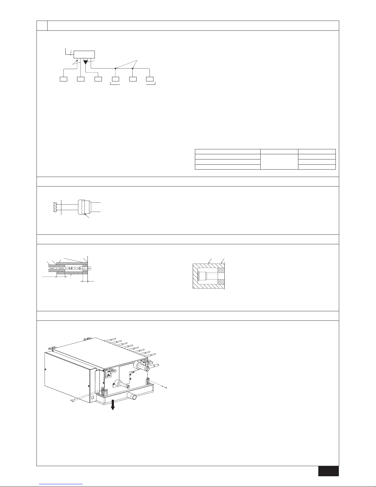
Ⓐ Inspection hole
Ⓑ On the side of outdoor unit piping
Ⓒ Control box
Ⓓ On the side of indoor unit piping
*1 Dimensions with which pipe connection can be handled at site
[Fig. 2.2.1]
INDOOR UNIT SIDE
450
130
*1
100
A
B
D
(700)
200
250
<B><A>
Ⓑ
Ⓑ
Ⓐ
Ⓓ
Ⓒ
450
C
200
<A> Top view
<B> Front view
[Fig. 2.3.1]
Model name A B C D
CMB-P104V-J
596
-
429
250
CMB-P106V-J
CMB-P108V-J
CMB-P1012V-J 911
573
CMB-P1016V-J 1135
CMB-P108V-JA 911
250 300
CMB-P1012V-JA
1135CMB-P1016V-JA
CMB-P1016V-KA
CMB-P104V-KB 596 - 429 250
Page 3
3
2.4
[Fig. 2.4.1]
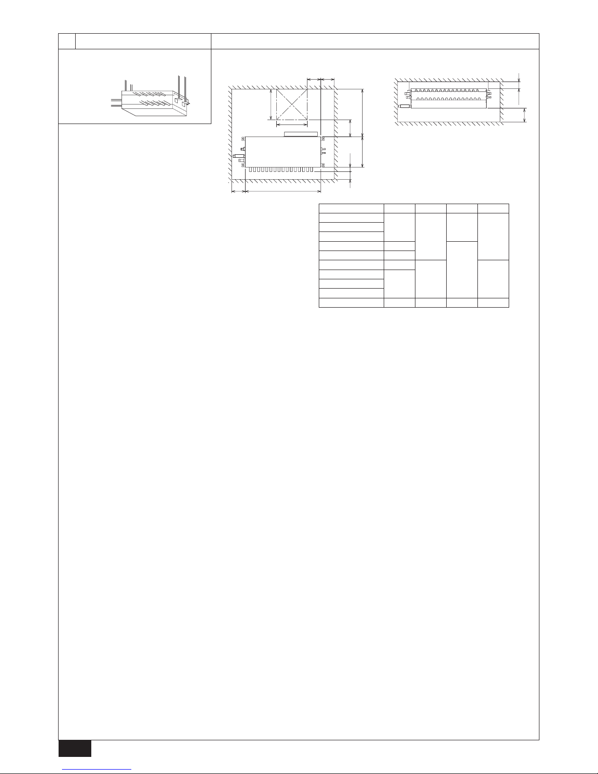
●Restrictions on piping length
PURY-(E)P200, 250, 300YNW-A, PQRY-P200, 250, 300YLM-A PURY-(E)P350, 400, 450, 500, 550YNW-A
PURY-(E)P700, 750, 800, 850, 900, 950, 1000, 1050, 1100YSNW-A
200
300
400
500
600
700
800
900
1000
10 20 30 40 50 60 70 80 90 100 110
Ⓑ
Ⓐ
200
300
400
500
600
700
800
900
1000
10 20 30 40 50 60 70 80 90 100 11 0
Ⓑ
Ⓐ
200
300
400
500
600
700
800
900
1000
10 20 30 40 50 60 70 80 90 100 11 0
Ⓑ
Ⓐ
PURY-(E)P400, 450, 500, 550, 600YSNW-A
PQRY-P350, 400, 450, 500, 550, 600YLM-A
PQRY-P400, 450, 500, 550, 600, 700, 750, 800, 850, 900YSLM-A
200
300
400
500
600
700
800
900
1000
10 20 30 40 50 60 70 80 90 100 11 0
Ⓑ
Ⓐ
PURY-(E)P650YSNW-A
200
300
400
500
600
700
800
900
1000
10 20 30 40 50 60 70
80 90 100 110
Ⓑ
Ⓐ
Ⓐ Total piping length (m) Ⓑ Piping length between outdoor (heat source) unit and main BC controller (m)
Page 4
4
3
3.2
[Fig. 3.2.1]
[Fig. 3.2.2]
Ⓑ
Ⓐ
Ⓐ
Ⓑ
ⒷⒷ
Ⓐ
<Ⓒ> <Ⓓ>
Ⓐ Within 1.5º
Ⓑ Drain socket
Ⓒ Viewed from the front of the control box Ⓓ Viewed from the drain socket side
4
4.1
[Fig. 4.1.1]
Ⓑ
Ⓒ
Ⓓ
Ⓔ
ⒻⒶ
Ⓐ
Ⓕ
Ⓐ
50
20
Ⓐ Indoor unit connecting port
Ⓑ Cutting point : ø9.52 (Liquid side) or ø15.88 (Gas side)
(Indoor unit model : above P50)
Ⓒ Cutting point : ø6.35 (Liquid side) or ø12.7 (Gas side)
(Indoor unit model : P50 or below)
Ⓓ Cut the piping at the cutting point
Ⓔ Have pipe expansion of indoor unit connecting port
Ⓕ Field pipe
Note:
Remove burr after cutting the piping to prevent entering the piping.
Check that there is no crack at the pipe expansion part.
Ⓐ
Ⓑ
Ⓕ
Ⓒ
Ⓓ
Ⓔ
14
30
(Top view)
30
14
CMB-P1012, 1016V-J
CMB-P108, 1012, 1016V-JA
CMB-P1016V-KA
Ⓐ Nut (not supplied)
Ⓑ Double nut (not supplied)
Ⓒ Hanging bolt ø10 (M10 screw) (not supplied)
Ⓓ Washer (with cushion) (supplied)
* Attach the cushion facing down.
Ⓔ Minimum 30 mm
Ⓕ Washer (without cushion) (supplied)
CMB-P104, 106, 108V-J,
CMB-P104V-KB
Page 5
5
4
4.1
[Fig. 4.1.2]
Ⓓ
ⒹⒹ
ⒹⒹⒽⒹ
Ⓐ
Ⓑ
Ⓕ*2
Ⓖ
*1
63-80 100-250 *3
Ⓒ
Ⓔ
Ⓐ To outdoor unit (Main BC controller)
Ⓑ End connection (brazing)
Ⓒ BC controller (Main BC controller / Sub BC controller)
Ⓓ Indoor unit
Ⓔ P50 or below
Ⓕ Combined piping kit (Model name: CMY-R160-J1)
Ⓖ Twinning pipe (Model name: CMY-Y102SS-G2, CMY-Y102LS-G2)
Ⓗ Up to three units for 1 branch hole; total capacity: 80 or below
(but same in cooling/heating mode)
*1. For connecting 15 to 50 model indoor units
Have pipe expansion of indoor unit connecting port by cutting the piping at
the cutting point which depends on the indoor unit capacity.
Note:
Remove burr after cutting the piping to prevent entering the piping.
Check that there is no crack at the pipe expansion part.
*2. To connect a unit with a capacity of 81 or above.
After combining two branches using an optionally available piping kit
(CMY-R160-J1), connect indoor units.
*3. Connection of plural indoor units with one connection (or joint pipe)
• Total capacity of connectable indoor units: 80 or below (250 or below with
joint pipe)
• Number of connectable indoor units: Maximum 3 Sets
• Twinning pipe: Use the twinning pipe for CITY MULTI Y Series (CMY-
Y102SS-G2, CMY-Y102LS-G2)
• Selection of refrigerant piping
Select the size according to the total capacity of indoor units to be installed
downstream.
Total capacity of indoor units Liquid line Gas line
140 or below
ø9.52
ø15.88
141 to 200 ø19.05
201 to 250 ø22.2
4.2
[Fig. 4.2.1]
Ⓑ
Ⓐ
Ⓐ Cut here
Ⓑ Remove brazed cap
4.3
[Fig. 4.3.1]
Ⓕ
Ⓔ
Ⓓ
Ⓐ
Ⓒ
Ⓑ
Ⓖ
Ⓒ
Ⓐ Insulating material for pipes (not supplied)
Ⓑ Bind here using band or tape.
Ⓒ Do not leave any opening.
Ⓓ Lap margin: more than 40 mm
Ⓔ Insulating material (not supplied)
Ⓕ Unit side insulating material
Ⓖ Minimum 30 mm
[Fig. 4.3.2]
ⒶⒷ
Ⓐ Insulating material (not supplied)
Ⓑ Bind here using band or tape.
4.4
[Fig. 4.4.1]
①
②
③
①
① Unscrew the two screws that are holding the side panel on the right side of the control
box.
② Tilt the drain pan.
③ Screw down the screws with the drain pan tilted.
Page 6
6
4
4.4
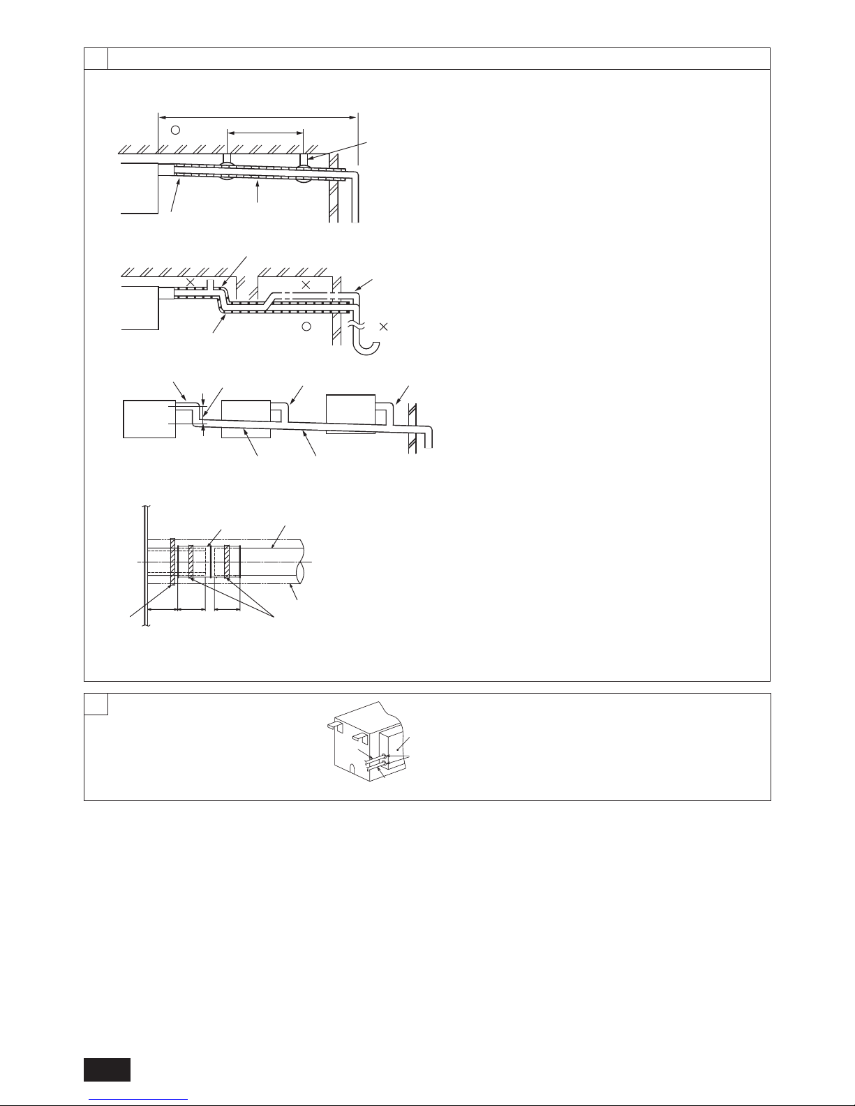
[Fig. 4.4.2]
Ⓐ
Ⓑ
Ⓒ
Ⓛ
Ⓜ
Ⓓ
Ⓖ
Ⓛ
Ⓓ
Ⓘ
Ⓗ
Ⓚ
Ⓑ
Ⓓ
Ⓔ
Max. 20 m
1.5-2 m
ⒻⒻ
Ⓙ
○ Correct piping
× Wrong piping
Ⓐ Insulation (9 mm or more)
Ⓑ Downward slope (1/100 or more)
Ⓒ Support metal
Ⓚ Air bleeder
Ⓛ Raised
Ⓜ Odor trap
Grouped piping
Ⓓ O.D. ø32 PVC TUBE
Ⓔ Make it as large as possible. About 10 cm.
Ⓕ Indoor unit
Ⓖ Make the piping size large for grouped piping.
Ⓗ Downward slope (1/100 or more)
Ⓘ O.D. ø38 PVC TUBE for grouped piping. (9 mm or more insulation)
Ⓙ BC controller
[Fig. 4.4.3]
Ⓐ
Ⓑ
Ⓒ
Ⓓ
Ⓓ
Ⓕ
Ⓗ
Ⓖ
Ⓔ
3230 25
Ⓐ BC controller
Ⓑ Tie band (supplied)
Ⓒ Visible part
Ⓓ Insertion margin
Ⓔ Drain hose (supplied)
Ⓕ Drain pipe (O.D. ø32 PVC TUBE, not supplied)
Ⓖ Insulating material (not supplied)
Ⓗ Tie band (supplied)
5
[Fig. 5.0.1]
Ⓑ
Ⓐ
Ⓒ
Ⓓ
Ⓐ Control box
Ⓑ Power source wiring
Ⓒ ø21 hole (closed rubber bushing)
Ⓓ Transmission wiring
Page 7
GB
7
1. Safety precautions
1.1. Before installation and electric work
► Before installing the unit, make sure you read all the
“Safety precautions”.
► The “Safety precautions” provide very important points
regarding safety. Make sure you follow them.
Symbols used in the text
Warning:
Describes precautions that should be observed to prevent danger of injury
or death to the user.
Caution:
Describes precautions that should be observed to prevent damage to the
unit.
Symbols used in the illustrations
: Indicates an action that must be avoided.
: Indicates that important instructions must be followed.
: Indicates a part which must be grounded.
: Beware of electric shock (This symbol is displayed on the main unit
label.) <Color: Yellow>
Warning:
Carefully read the labels afxed to the main unit.
HIGH VOLTAGE WARNING:
• Control box houses high-voltage parts.
• When opening or closing the front panel of the control box, do not let it
come into contact with any of the internal components.
• Before inspecting the inside of the control box, turn off the power, keep
the unit off for at least 10 minutes.
Warning:
• If the supply cord is damaged, it must be replaced by the manufacturer,
its service agent or similarly qualied persons in order to avoid a hazard.
• This appliance is not intended for use by persons (including children) with
reduced physical, sensory or mental capabilities, or lack of experience
and knowledge, unless they have been given supervision or instruction
concerning use of the appliance by a person responsible for their safety.
• This appliance is intended to be used by expert or trained users in shops,
in light industry and on farms, or for commercial use by lay persons.
• Do not use refrigerant other than the type indicated in the manuals provided with the unit and on the nameplate.
- Doing so may cause the unit or pipes to burst, or result in explosion or re
during use, during repair, or at the time of disposal of the unit.
- It may also be in violation of applicable laws.
- MITSUBISHI ELECTRIC CORPORATION cannot be held responsible for
malfunctions or accidents resulting from the use of the wrong type of
refrigerant.
• Ask the dealer or an authorized technician to install the air conditioner.
- Improper installation by the user may result in water leakage, electric shock,
or re.
• Install the unit at a place that can withstand its weight.
- Failure to do so may cause the unit to fall down, resulting in injuries and
damage to the unit.
• Use the specied cables for wiring. Make the connections securely so that
the outside force of the cable is not applied to the terminals.
- Inadequate connection and fastening may generate heat and cause a re.
• Prepare for earthquakes and install the unit at the specied place.
- Improper installation may cause the unit to fall down and result in injury and
damage to the unit.
• Always use accessories specied by Mitsubishi Electric.
- Ask an authorized technician to install the accessories. Improper installation
by the user may result in water leakage, electric shock, or re.
• Never repair the unit. If the air conditioner must be repaired, consult the
dealer.
- If the unit is repaired improperly, water leakage, electric shock, or re may
result.
• Do not touch the refrigerant pipes.
- Improper handling may result in injury.
• When handling this product, always wear protective equipment.
EG: Gloves, full arm protection namely boiler suit, and safety glasses.
- Improper handling may result in injury.
• If refrigerant gas leaks during installation work, ventilate the room.
- If the refrigerant gas comes into contact with a ame, poisonous gases will
be released.
• Install the air conditioner according to this Installation Manual.
- If the unit is installed improperly, water leakage, electric shock, or re may
result.
• Have all electric work done by a licensed electrician according to “Electric
Facility Engineering Standard” and “Interior Wire Regulations”and the instructions given in this manual and always use a dedicated power supply.
- If the power source capacity is inadequate or electric work is performed
improperly, electric shock and re may result.
• Keep the electric parts away from water (washing water etc.).
- It might result in electric shock, catching re or smoke.
• Securely install the cover of control box.
- If the cover is not installed properly, dust or water may enter the outdoor
unit and re or electric shock may result.
• When installing and moving the air conditioner to another site, do not
charge it with a refrigerant different from the refrigerant specied on the
unit.
- If a different refrigerant or air is mixed with the original refrigerant, the
refrigerant cycle may malfunction and the unit may be damaged.
• If the air conditioner is installed in a small room, measures must be taken
to prevent the refrigerant concentration from exceeding the safety limit if
the refrigerant should leak.
- Consult the dealer regarding the appropriate measures to prevent the
safety limit from being exceeded. Should the refrigerant leak and cause the
safety limit to be exceeded, hazards due to lack of oxygen in the room
could result.
• When moving and reinstalling the air conditioner, consult the dealer or an
authorized technician.
- If the air conditioner is installed improperly, water leakage, electric shock, or
re may result.
• After completing installation work, make sure that refrigerant gas is not
leaking.
- If the refrigerant gas leaks and is exposed to a fan heater, stove, oven, or
other heat source, it may generate noxious gases.
• Do not reconstruct or change the settings of the protection devices.
- If the pressure switch, thermal switch, or other protection device is shorted
or operated forcibly, or parts other than those specied by Mitsubishi
Electric are used, re or explosion may result.
• To dispose of this product, consult your dealer.
• The installer and system specialist shall secure safety against leakage
according to local regulation or standards.
- Choose the appropriate wire size and the switch capacities for the main
power supply described in this manual if local regulations are not available.
• Pay special attention to the place of installation, such as basement, etc.
where refrigeration gas can accumulate, since refrigerant is heavier than
the air.
• Children should be supervised to ensure that they do not play with the
appliance.
Contents
1. Safety precautions ........................................................................................ 7
1.1. Before installation and electric work ........................................... 7
1.2. Precautions for devices that use R410A refrigerant ...................8
1.3. Before installation ....................................................................... 8
1.4. Before installation (relocation) - electrical work .......................... 8
1.5. Before starting the test run ......................................................... 8
2. Selecting an installation site ......................................................................... 9
2.1. About the product ....................................................................... 9
2.2. Installation site ............................................................................ 9
2.3. Securing installation and service space ...................................... 9
2.4. Checking the installation site .................................................... 10
3. Installing BC controller ............................................................................... 13
3.1. Checking the accessories with BC controller ............................ 13
3.2. Installing BC controllers ............................................................ 13
4. Connecting refrigerant pipes and drain pipes............................................. 13
4.1. Connecting refrigerant pipes ..................................................... 13
4.2. Refrigerant piping work ............................................................. 15
4.3. Insulating refrigerant pipes ....................................................... 15
4.4. Drain piping work ...................................................................... 15
5. Electrical work ............................................................................................ 16
6. Setting addresses and operating units ....................................................... 16
7. Test run .......................................................................................................16
Page 8

GB
8
1.2. Precautions for devices that use R410A
refrigerant
Warning:
• Do not use refrigerant other than the type indicated in the manuals provided with the unit and on the nameplate.
- Doing so may cause the unit or pipes to burst, or result in explosion or re
during use, during repair, or at the time of disposal of the unit.
- It may also be in violation of applicable laws.
- MITSUBISHI ELECTRIC CORPORATION cannot be held responsible for
malfunctions or accidents resulting from the use of the wrong type of
refrigerant.
Caution:
• Do not use existing refrigerant piping.
- The old refrigerant and refrigerant oil in the existing piping contains a large
amount of chlorine which may cause the refrigerant oil of the new unit to
deteriorate.
- R410A is a high-pressure refrigerant and can cause the existing piping to
burst.
• Use refrigerant piping made of phosphorus deoxidized copper and copper
alloy seamless pipes and tubes. In addition, be sure that the inner and
outer surfaces of the pipes are clean and free of hazardous sulphur, oxides,
dust/dirt, shaving particles, oils, moisture, or any other contaminant.
- Contaminants on the inside of the refrigerant piping may cause the refrigerant
residual oil to deteriorate.
• Store the piping to be used during installation indoors and keep both ends
of the piping sealed until just before brazing. (Store elbows and other
joints in a plastic bag.)
- If dust, dirt, or water enters the refrigerant cycle, deterioration of the oil and
compressor failure may result.
• Apply a small amount of ester oil, ether oil, or alkyl benzene to ares. (for
indoor unit)
- Inltration of a large amount of mineral oil may cause the refrigerant oil to
deteriorate.
• Use liquid refrigerant to ll the system.
- If gas refrigerant is used to ll the system, the composition of the refrigerant
in the cylinder will change and performance may drop.
• Do not use a refrigerant other than R410A.
- If another refrigerant (R22, etc.) is mixed with R410A, the chlorine in the
refrigerant may cause the refrigerant oil to deteriorate.
• Use a vacuum pump with a reverse ow check valve.
- The vacuum pump oil may ow back into the refrigerant cycle and cause
the refrigerant oil to deteriorate.
• Do not use the following tools that are used with conventional refrigerants.
(Gauge manifold, charge hose, gas leak detector, reverse ow check valve,
refrigerant charge base, refrigerant recovery equipment)
- If the conventional refrigerant and refrigerant oil are mixed in the R410A,
the refrigerant may deteriorate.
- If water is mixed in the R410A, the refrigerant oil may deteriorate.
- Since R410A does not contain any chlorine, gas leak detectors for conventional
refrigerants will not react to it.
• Do not use a charging cylinder.
- Using a charging cylinder may cause the refrigerant to deteriorate.
• Do not use antioxidant or leak-detection additive.
• Be especially careful when managing the tools.
- If dust, dirt, or water gets into the refrigerant cycle, the refrigerant may
deteriorate.
1.3. Before installation
Caution:
• Do not install the unit where combustible gas may leak.
- If the gas leaks and accumulates around the unit, an explosion may result.
• Do not use the air conditioner where food, pets, plants, precision instruments, or artwork are kept.
- The quality of the food, etc. may deteriorate.
• Do not use the air conditioner in special environments.
- Oil, steam, sulfuric smoke, etc. can signicantly reduce the performance of
the air conditioner or damage its parts.
• When installing the unit in a hospital, communication station, or similar
place, provide sufcient protection against noise.
- Inverter equipment, private power generator, high-frequency medical
equipment, or radio communication equipment may cause the air
conditioner to operate erroneously, or fail to operate. On the other hand, the
air conditioner may affect such equipment by creating noise that disturbs
medical treatment or image broadcasting.
• Do not install the unit on or over things that are subject to water damage.
- When the room humidity exceeds 80 % or when the drain pipe is clogged,
condensation may drip from the indoor unit or BC controller. Perform
collective drainage work together with the outdoor unit, as required.
• Make sure to remove the foamed styrol between the unit and the drain
pan.
1.4. Before installation (relocation) - electrical work
Caution:
• Ground the unit.
- Do not connect the ground wire to gas or water pipes, lightning rods, or
telephone ground lines. Improper grounding may result in electric shock.
• Install the power cable so that tension is not applied to the cable.
- Tension may cause the cable to break and generate heat and cause a re.
• Install a leak circuit breaker, as required.
- If a leak circuit breaker is not installed, electric shock may result.
• Use power line cables of sufcient current carrying capacity and rating.
- Cables that are too small may leak, generate heat, and cause a re.
• Use only a circuit breaker and fuse of the specied capacity.
- A fuse or circuit breaker of a larger capacity, or the use of substitute simple
steel or copper wire may result in a general unit failure or re.
• Do not wash the air conditioner units.
- Washing them may cause an electric shock.
• Be careful that the installation base is not damaged by long use.
- If the damage is left uncorrected, the unit may fall and cause personal injury
or property damage.
• Install the drain piping according to this Installation Manual to ensure
proper drainage. Wrap thermal insulation around the pipes to prevent
condensation.
- Improper drain piping may cause water leakage causing damage to
furniture and other possessions.
• Be very careful about transporting the product.
- One person should not carry the product. Its weight is in excess of 20 kg.
- Some products use PP bands for packaging. Do not use any PP bands as a
means of transportation. It is dangerous.
• Safely dispose of the packing materials.
- Packing materials, such as nails and other metal or wooden parts, may
cause stabs or other injuries.
- Tear apart and throw away plastic packaging bags so that children will not
play with them. If children play with a plastic bag which has not been torn
apart, they face the risk of suffocation.
1.5. Before starting the test run
Caution:
• Turn on the power at least 12 hours before starting operation.
- Starting operation immediately after turning on the main power switch can
result in irreversible damage to internal parts. Keep the power switch turned
on during the operational season.
• Do not touch the switches with wet ngers.
- Touching a switch with wet ngers can result in an electric shock.
• Do not touch the refrigerant pipes during and immediately after operation.
- During and immediately after operation, the refrigerant pipes may be hot or
cold, depending on the condition of the refrigerant owing through the
refrigerant piping, compressor, and other refrigerant cycle parts. Your hands
may suffer burns or frostbite if you touch the refrigerant pipes.
• Do not operate the air conditioner with the panels and guards removed.
- Rotating, hot, or high-voltage parts can cause injuries.
• Do not turn off the power immediately after stopping operation.
- Always wait at least 5 minutes before turning off the power. Otherwise,
drainage water leakage or mechanical failure of sensitive parts may occur.
Page 9
GB
9
2. Selecting an installation site
2.1. About the product
Warning:
• Do not use refrigerant other than the type indicated in the manuals provided with the unit and on the nameplate.
- Doing so may cause the unit or pipes to burst, or result in explosion or re
during use, during repair, or at the time of disposal of the unit.
- It may also be in violation of applicable laws.
- MITSUBISHI ELECTRIC CORPORATION cannot be held responsible for
malfunctions or accidents resulting from the use of the wrong type of
refrigerant.
• This unit uses R410A-type refrigerant.
• Piping for systems using R410A may be different from that for systems using
conventional refrigerant because the design pressure in systems using
R410A is higher. Refer to the Data Book for more information.
• Some of the tools and equipment used for installation with systems that use
other types of refrigerant cannot be used with the systems using R410A.
Refer to the Data Book for more information.
• Do not use the existing piping, as it contains chlorine, which is found in
conventional refrigerating machine oil and refrigerant. This chlorine will
deteriorate the refrigerant machine oil in the new equipment. The existing
piping must not be used as the design pressure in systems using R410A is
higher than that in the systems using other types of refrigerant and the
existing pipes may burst.
2.2. Installation site
• Install the unit in a place not exposed to rain. The BC controller is designed to
be installed indoors.
• Install the unit with adequate space around it for servicing.
• Do not install the unit in a place that would result in the piping length
restrictions being exceeded.
• Install the unit in a place not exposed to direct radiant heat from other heat
sources.
• Do not install the unit in any oily steamy place or near any machine that
generates high frequencies. Doing so may cause a risk of re, erroneous
operation or dew drop.
• Allow enough space and access to ensure water piping, refrigerant piping
and electrical wiring can be easily connected.
• Avoid places exposed to the generation, inow, accumulation or leakage of
ammable and sulfuric gases.
• Ensure a downward gradient of at least 1/100 for drain piping.
• Properly install the unit on a stable, load-bearing surface.
• Do not install the unit in a place subject to a large amount of steam. Using the
unit in a humid environment may cause condensation during a cooling
operation.
• If the inside of the ceiling on which the unit is installed becomes hot and
humid, operating the unit for a long time in such environment may cause
condensation. However, it poses no problem because condensation water will
ow into a drain pan. Though an area where condensation occurred may be
colored in white, it does not affect normal operation of the unit.
• Make sure that condensation water of the unit does not come into contact
with surrounding wirings.
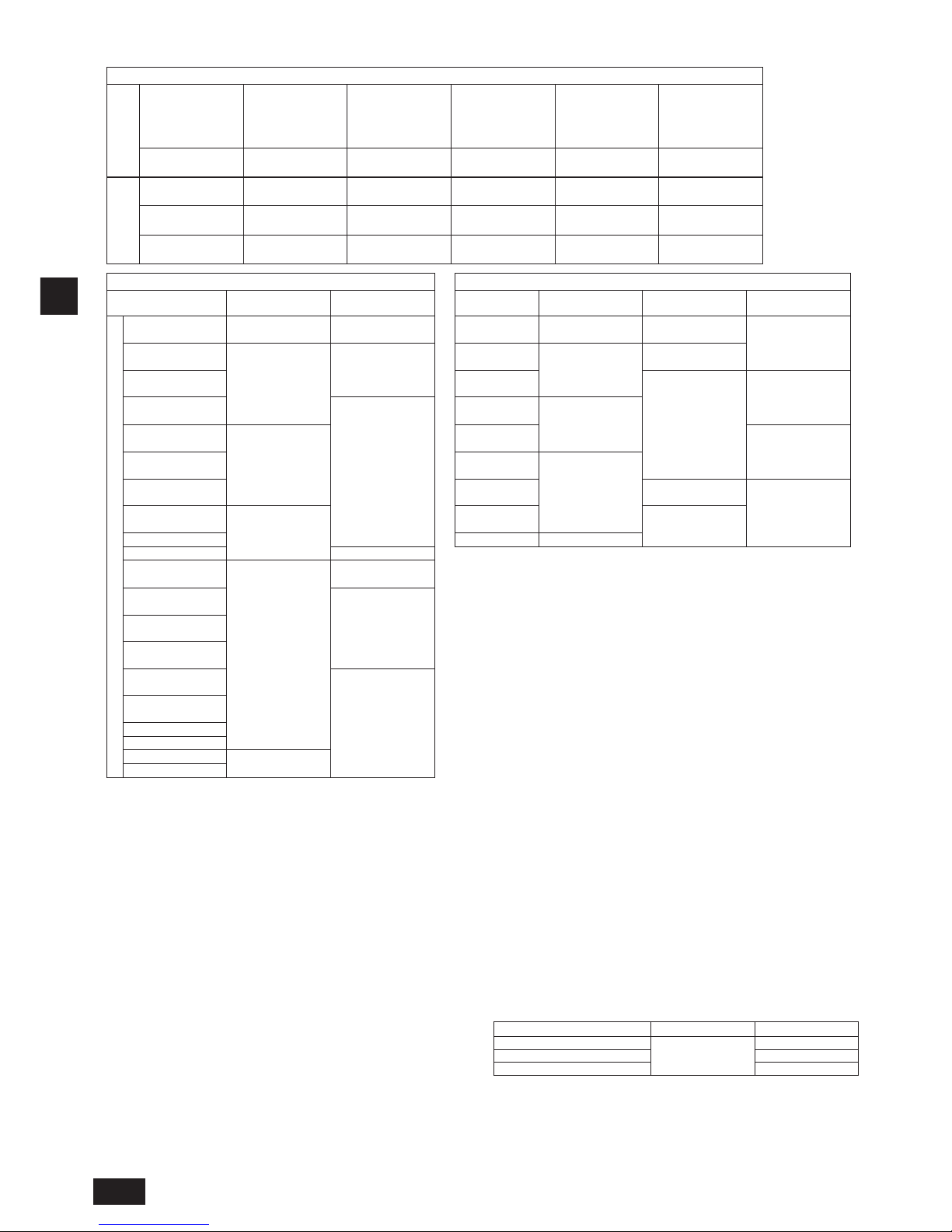
1. For hanging from the ceiling [Fig. 2.2.1] (P.2)
• Provide an inspection hole 450 mm square in the ceiling surface as shown in
[Fig. 2.3.1] (P.2).
• Install the unit in a suitable location (such as in the ceiling of a corridor or in
the bathroom etc) away from places regularly occupied. Avoid installing in the
center of a room.
• Ensure a pull out strength of at least 60 kg per bolt for hanging bolts.
• Be sure to install the BC controller horizontally.
• Install the unit in a location where the noise from the BC controller will not
directly be heard.
• Install the unit in a location where the noise from the unit will not be a
problem. (Install indoor unit and BC controller at least 5 m away from each
other when installed in a space with low background noise, e.g., hotel rooms).
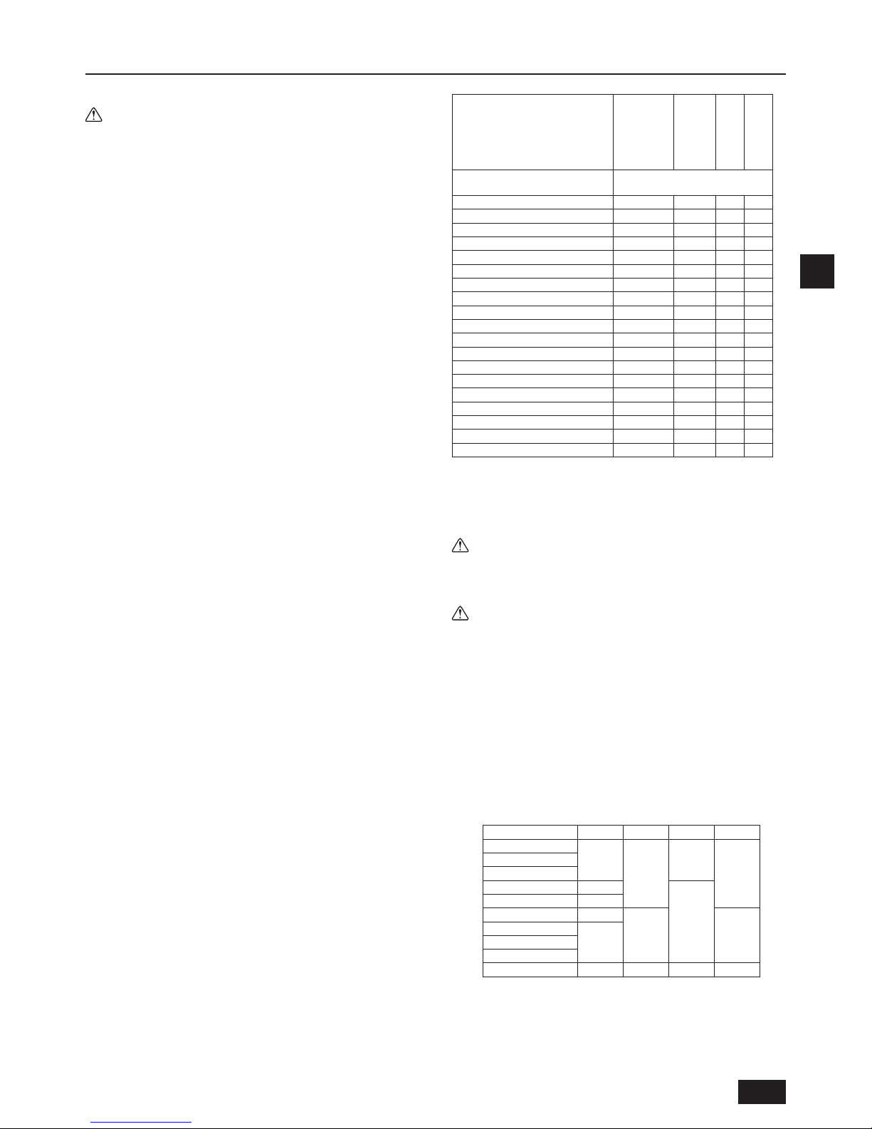
Sound pressure level is as follows.
Sound pressure level [dB] <A scale>
BC Controller model name
CMB-P104V-J
CMB-P106V-J
CMB-P108V-J
CMB-P1012V-J
CMB-P1016V-J
CMB-P108V-JA
CMB-P1012V-JA
CMB-P1016V-JA
CMB-P1016V-KA
CMB-P104V-KB
Connected outdoor (heat source)
unit capacity
Maximum value during normal
operation or defrost operation
(E)P200 49 53 55 49
(E)P250 49 53 55 49
(E)P300 49 53 55 49
(E)P350 53 55 55 53
(E)P400 - 56 55 (E)P450 - 56 55 (E)P500 - 56 55 (E)P550 - 56 55 (E)P600 - 56 55 (E)P650 - 56 55 (E)P700 - 56 55 (E)P750 - 56 55 (E)P800 - 56 55 (E)P850 - 56 55 (E)P900 - 56 55 (E)P950 - - 55 (E)P1000 - - 55 (E)P1050 - - 55 (E)P1100 - - 55 -
*1. The sound pressure level values were obtained in an anechoic room.
Actual sound pressure level is usually greater than that measured in an
anechoic room due to the ambient noise and deection sound.
*2. The sound pressure level values were obtained at the location below
1.5 m from the unit.
*3. The solenoid valve switching sound is 56 dB regardless of the unit model.
Warning:
Be sure to install the unit in a place that can sustain the entire weight.
If there is a lack of strength, it may cause the unit to fall down, resulting in
an injury.
Caution:
Be sure to install the unit horizontally.
2.3. Securing installation and service space
1. For hanging from the ceiling
(This is a reference view showing the least installation space.)
[Fig. 2.3.1] (P.2)
<A> Top view
<B> Front view
Ⓐ Inspection hole
Ⓑ On the side of outdoor unit piping
Ⓒ Control box
Ⓓ On the side of indoor unit piping
*1 Dimensions with which pipe connection can be handled at site
Model name A B C D
CMB-P104V-J
596
-
429
250
CMB-P106V-J
CMB-P108V-J
CMB-P1012V-J 911
573
CMB-P1016V-J 1135
CMB-P108V-JA 911
250 300
CMB-P1012V-JA
1135CMB-P1016V-JA
CMB-P1016V-KA
CMB-P104V-KB 596 - 429 250
Page 10
GB
10
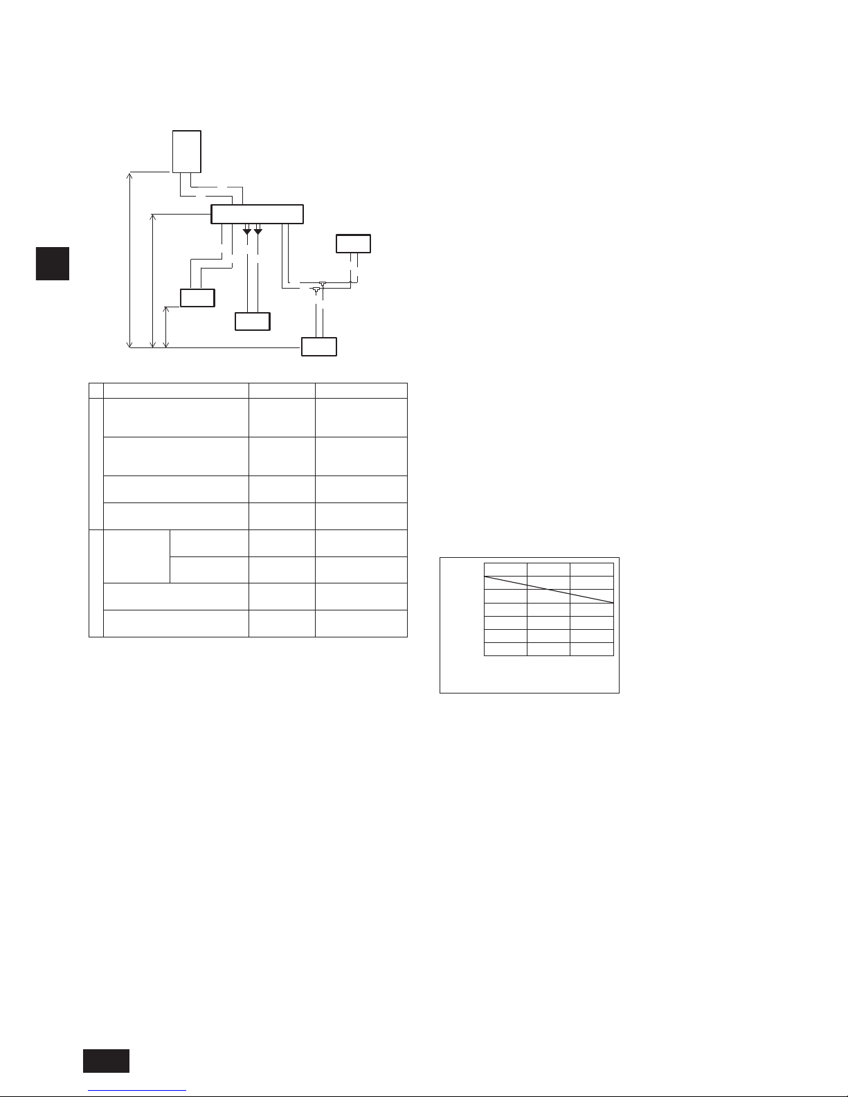
2.4. Checking the installation site
Check that the difference of elevation between indoor and outdoor units and the length of refrigerant piping are within the following limitations.
1. CMB-P104, 106, 108, 1012, 1016V-J (In the case the outdoor unit is 14-hp (P350 model) or below, and 16 or fewer ports are used.)
CMB-P108, 1012, 1016V-JA, CMB-P1016V-KA (When no Sub BC controller is connected)
Ⓑ
Ⓓ
A
A
a
a
b
b
Ⓐ
Ⓔ
Ⓓ
Ⓓ
B
B
c
c
d
d
Ⓕ
Ⓖ
H
H1
h1
h2
(Unit: m)
Item Piping portion Allowable value
Length
Total piping length
"A+B+a+b
+c+d"
Not to exceed the
maximum refrigerant
piping length *1
Longest piping length "A+B+c"
165 or less
(Equivalent length of
190 or less)
Between outdoor (heat source)
unit and BC controller
"A" 110 or less
Between indoor units and BC
controller
"a" or "b" or
"B+c" or "B+d"
60 or less *2
Difference of height
Between
indoor and
outdoor (heat
source) units
Above outdoor
(heat source) unit
"H" 50 or less
Below outdoor
(heat source) unit
"H1" 40 or less
Between indoor units and BC
controller
"h1"
15 or less
(10 or less *3)
Between indoor units "h2"
30 or less
(20 or less *3)
Ⓐ Outdoor unit (Heat source unit)
Ⓑ BC controller (Main)
Ⓒ BC controller (Sub)
Ⓓ Indoor unit (Total capacity of downstream indoor unit: 15 to 80)
Ⓔ Indoor unit (Total capacity of downstream indoor unit: 100 to 250)
Ⓕ Twinning pipe (Model name: CMY-R160-J1)
Ⓖ 2-Branch Joint Pipe
Notes:
*1 Refer to “Restrictions on piping length” on P. 3.
*2
Refer to the graph “Distance between main BC controller and farthest
indoor unit (direct connection)”. (However, when P200 or P250 model of
indoor unit is connected, the maximum allowable distance between BC
controller and farthest indoor unit is 40 m.)
*3
The values in the parentheses show the maximum piping length to be
followed when the connection capacity of the indoor unit is 200 or above.
*4 In the system to which indoor units of the P200 model or above are
connected, neither a branch joint nor a branch header may be used.
*5 Do not connect the P200 or P250 models of indoor units and other
models of indoor units at the same port.
*6 In the system to which indoor units of the P100 through P140 models
are connected, merge the two ports before connecting them. (Set DIP
SW4-6 on the BC controller to ON.)
*7 It is possible to connect the P100 through P140 models of indoor units to
a single port. (Set DIP SW4-6 to OFF.) Note that the cooling capacity will
somewhat decrease. (The factory setting for DIP SW4-6 is OFF.)
When connecting only PEFY-P50/63/71/80VMHS2-E units, set the
dipswitches SW4-1 and SW4-6 on the BC controller to ON.
*8 Indoor units that are connected to the same branch joint cannot be
simultaneously operated in different operation modes.
*9 When connecting PEFY-P50/63/71/80VMHS2-E units to two ports, use a
Joint Pipe Kit CMY-R160-J1.
Distance between main BC controller
and farthest indoor unit (direct connection)
Distance between BC controller
and farthest indoor unit (m)
15105
20
10
0
0
70
60
50
40
30
Height difference between
BC controller and farthest indoor unit (m)
*10 For connecting 15 to 50 model indoor units
Have pipe expansion of indoor unit connecting port by cutting the piping at
the cutting point which depends on the indoor unit capacity.
Unit 1
Page 11
GB
11
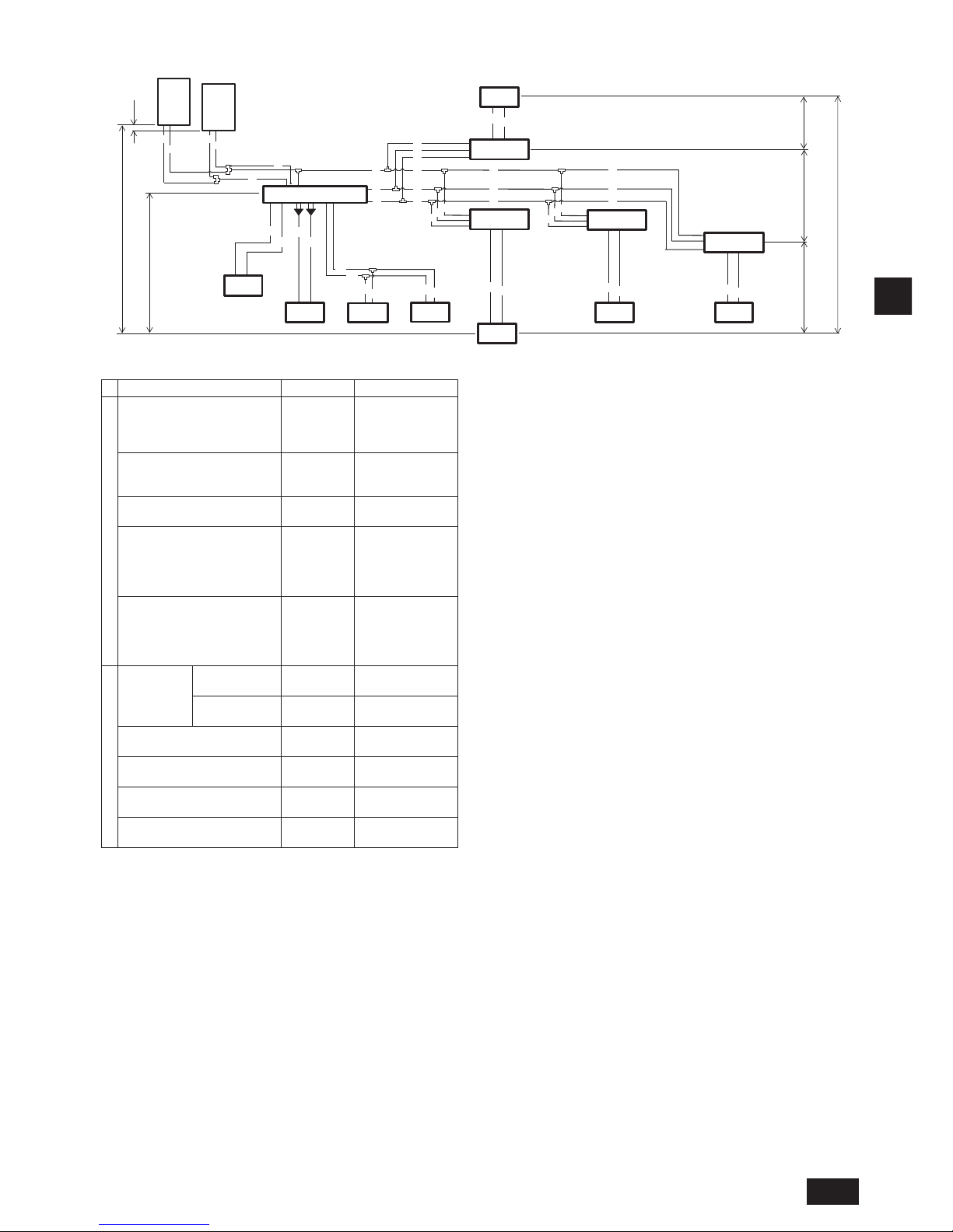
2. CMB-P108, 1012, 1016V-JA, CMB-P1016V-KA (When a Sub BC controller is connected)
Ⓓ
a
a
b
b
Ⓐ
Ⓔ
Ⓓ
Ⓓ
B
B
c
c
d
d
Ⓕ
Ⓖ
Ⓐ
Ⓒ
Ⓒ
Ⓒ
Ⓓ
Ⓓ
K
K
L
L
A
C
C
C
D
D
D
E
E
Ⓓ
Ⓒ
G
G
G
J
J
J
M
M
M
F
F
F
e
e
f
f
g
g
j
j
*1
Ⓖ
Ⓓ
h4
H
H1
h1
h1
h1 h3
h2
Ⓑ
E
Ⓖ
Ⓖ
A
(Unit: m)
Item Piping portion Allowable value
Length
Total piping length
"K+L+A+B+C
+D+E+F+G+J
+M+a+b+c+d
+e+f+g+j"
Not to exceed the
maximum refrigerant
piping length *1
Longest piping length
"K(L)+A+C
+E+G+J+j"
165 or less
(Equivalent length of
190 or less)
Between outdoor (heat source)
unit and Main BC controller
"K(L)+A" 110 or less
Direct connection between indoor
units and (Main or Sub) BC
controller
"a" or "b" or
"B+c" or
"B+d" or "e"
or "f" or "g" or
"j"
60 or less *2
Between indoor units and Main
BC controller via Sub BC
controller
"C+D+e" or
"C+E+F+f" or
"
C+E+G+M+g
"
or
"C+E+G+J+j"
90 or less *3
Difference of height
Between
indoor and
outdoor (heat
source) units
Above outdoor
(heat source) unit
H 50 or less
Below outdoor
(heat source) unit
H1 40 or less
Between BC controller (Both Main
and Sub) and indoor unit
h1
15 or less
(10 or less *4)
Between indoor units h2
30 or less
(20 or less *4)
Between BC controller (Both Main
and Sub) and Sub BC controller
h3 15 or less
Between outdoor (heat source)
units
h4 0.1 or less
Ⓐ Outdoor unit (Heat source unit)
Ⓑ BC controller (Main)
Ⓒ BC controller (Sub)
Ⓓ Indoor unit (Total capacity of downstream indoor unit: 15 to 80)
Ⓔ Indoor unit (Total capacity of downstream indoor unit: 100 to 250)
Ⓕ Twinning pipe (Model name: CMY-R160-J1)
Ⓖ 2-Branch Joint Pipe
Notes:
*1 Refer to “Restrictions on piping length” on P. 3.
*2 Refer to Fig. 1.
(However, when P200 or P250 model of indoor unit is
connected, the maximum allowable distance between BC controller and
farthest indoor unit is 40 m.)
*3 When the piping length or the height difference exceeds the restriction
specied in Fig. 1, connect a sub BC controller to the system. The
restriction for a system with a sub BC controller is shown in Fig. 2.
When a given system conguration falls within the shaded area in Fig.
2, increase the size of the high-pressure pipe and the liquid pipe
between the main and sub BC controller by one size. When using P32,
P40, P50, P100, or P125 model of indoor units, increase the size of the
liquid branch pipe between the sub BC controller and indoor unit by
one size.
When using P140 or larger model of indoor units, the restriction shown
in Fig. 1 cannot be exceeded.
*4 The values in the parentheses show the maximum piping length to be
followed when the connection capacity of the indoor unit is 200 or
above.
*5 In the system to which indoor units of the P200 model or above are
connected, neither a branch joint nor a branch header may be used.
*6 Do not connect the P200 or P250 models of indoor units and other
models of indoor units at the same port.
*7 In the system to which indoor units of the P100 through P140 models
are connected, merge the two ports before connecting them. (Set DIP
SW4-6 on the BC controller to ON.)
*8 It is possible to connect the P100 through P140 models of indoor units
to a single port. (Set DIP SW4-6 to OFF.) Note that the cooling capacity
will somewhat decrease. (The factory setting for DIP SW4-6 is OFF.)
When connecting only PEFY-P50/63/71/80VMHS2-E units, set the
dipswitches SW4-1 and SW4-6 on the BC controller to ON.
*9 Indoor units that are connected to the same branch joint cannot be
simultaneously operated in different operation modes.
*10 When connecting PEFY-P50/63/71/80VMHS2-E units to two ports, use a
Joint Pipe Kit CMY-R160-J1.
*11 The maximum total capacity of indoor units that can be connected to
each Sub BC controller is P350.
*12 Sub BC controller cannot be used at Ⓑ.
*13 For connecting 15 to 50 model indoor units
Have pipe expansion of indoor unit connecting port by cutting the piping at
the cutting point which depends on the indoor unit capacity.
*14 Up to 11 Sub BC controllers can be connected.
Unit 1
Unit 2
Page 12
GB
12
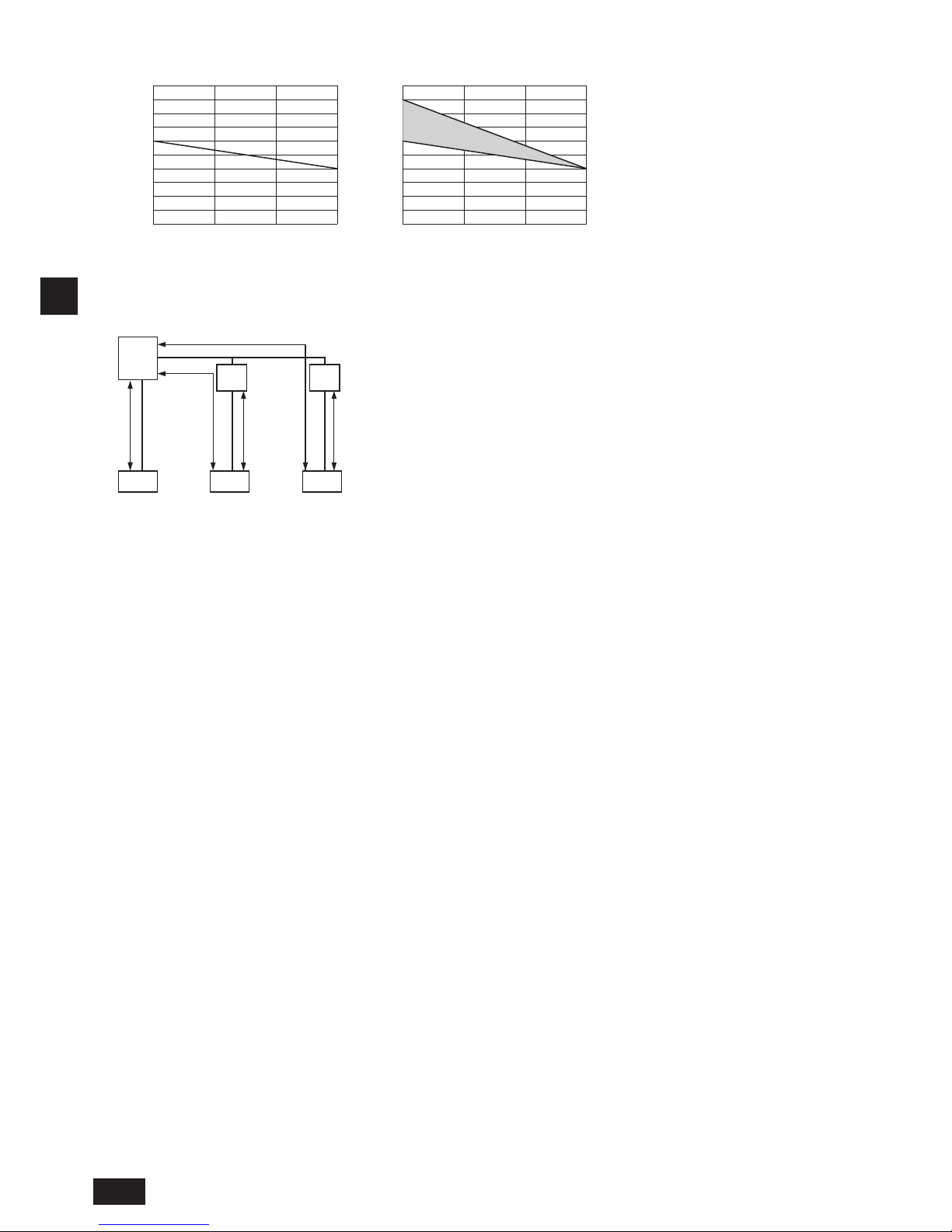
Piping length and height between indoor unit and BC controller
Pipe length between Main or Sub BC
controller and indoor unit (m)
0 5 10 15
0 5 10 15
10
20
30
40
50
60
70
80
90
100
10
20
30
40
50
60
70
80
90
100
Height difference between
the main BC controller and indoor unit (m)
Height difference between
the main BC controller and indoor unit (m)
*3 When the piping length or the height difference exceeds the restriction
specied in Fig. 1, connect a sub BC controller to the system. The
restriction for a system with a sub BC controller is shown in Fig. 2.
When a given system conguration falls within the shaded area in Fig.
2, increase the size of the high-pressure pipe and the liquid pipe
between the main and sub BC controller by one size. When using P32,
P40, P50, P100, or P125 model of indoor units, increase the size of the
liquid branch pipe between the sub BC controller and indoor unit by
one size.
When using P140 or larger model of indoor units, the restriction shown
in Fig. 1 cannot be exceeded.
*3
Pipe length between Main BC controller,
Sub BC controller, and indoor unit (m)
Fig. 1 Fig. 2
Fig. 1
BC
Sub
BC
Fig. 2
Fig. 1
Fig. 2
Sub
BC
Fig. 1
Indoor
unit
Indoor
unit
Indoor
unit
Page 13
GB
13
3. Installing BC controller
3.1. Checking the accessories with BC controller
The following items are supplied with each BC controller.
Model name
CMBP104V-J
P106V-J
P108V-J
P1012V-J
P1016V-J
CMBP108V-JA
P1012V-JA
P1016V-JA
CMBP1016V-KA
CMBP104V-KB
Item Qty
①
Drain hose 1 1 1 1
②
Tie band 3 3 3 3
③
Washer for
construction
2 kinds
(4 each)
2 kinds
(4 each)
2 kinds
(4 each)
2 kinds
(4 each)
3.2. Installing BC controllers
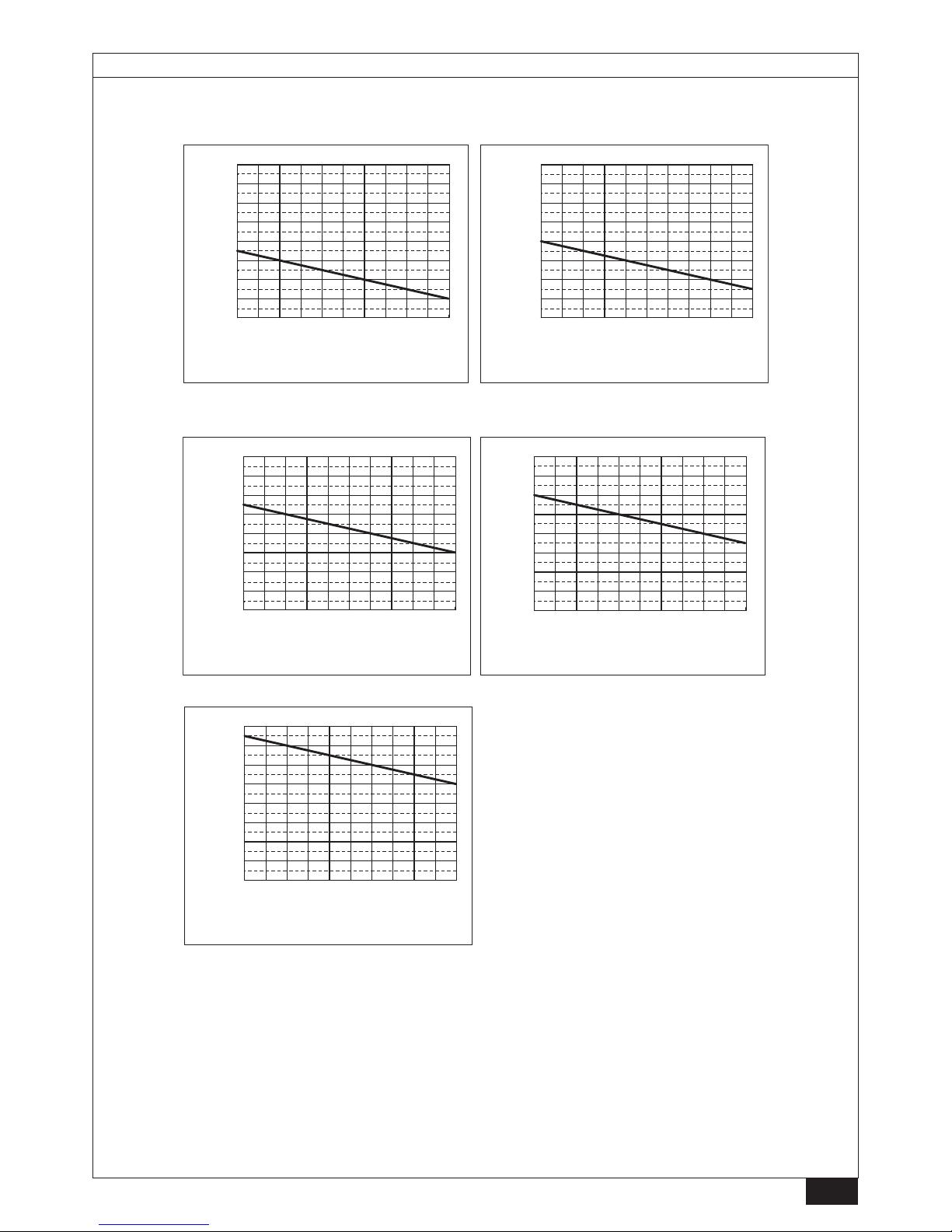
Installing hanging bolts
Install locally procured hanging bolts (threaded rod) following the procedure
given in the gure. The hanging bolt size is ø10 (M10 screw).
To hang the unit, use a lifting machine to lift and pass it through the hanging bolts.
[Fig. 3.2.1] (P.4)
Ⓐ Nut (not supplied)
Ⓑ Double nut (not supplied)
Ⓒ Hanging bolt ø10 (M10 screw) (not supplied)
Ⓓ Washer (with cushion) (supplied)
* Attach the cushion facing down.
Ⓔ Minimum 30 mm
Ⓕ Washer (without cushion) (supplied)
► Be sure to install the BC controller horizontally, using a level. If the
controller is installed at an angle, drain water may leak out. If the
controller is slanted, loosen the xing nuts on the hanging brackets to
adjust its position.
► Provide a downward pitch of 1.5º or below to the BC controller.
► Do not place the BC controller directly on the oor because the drain
pan needs to be installed in a tilted position.
[Fig. 3.2.2] (P.4)
Ⓐ Within 1.5º
Ⓑ Drain socket
Ⓒ Viewed from the front of the control box
Caution:
Be sure to install the unit horizontally.
4. Connecting refrigerant pipes and drain pipes
4.1. Connecting refrigerant pipes
1. Connect the liquid and gas pipes of each indoor unit to the same (correct)
end connection numbers as indicated on the indoor unit connection section
of each BC controller. If connected to wrong end connection numbers, there
will be no normal operation.
2. List indoor unit model names in the name plate on the BC controller control
box (for identication purposes), and BC controller end connection numbers
and address numbers in the name plate on the indoor unit side.
3. If the number of ports is greater than the number of indoor units to be
connected, use any ports.
Seal unused end connections using cover caps just as they were capped
when shipped from the factory. Not replacing on end cap will lead to
refrigerant leak-age.
4. When using CMY-Y102S-G2, CMY-Y102L-G2, CMY-Y202S-G2, CMYR201S-G, CMY-R202S-G, CMY-R203S-G, CMY-R204S-G, or CMY-R205SG, connect it horizontally.
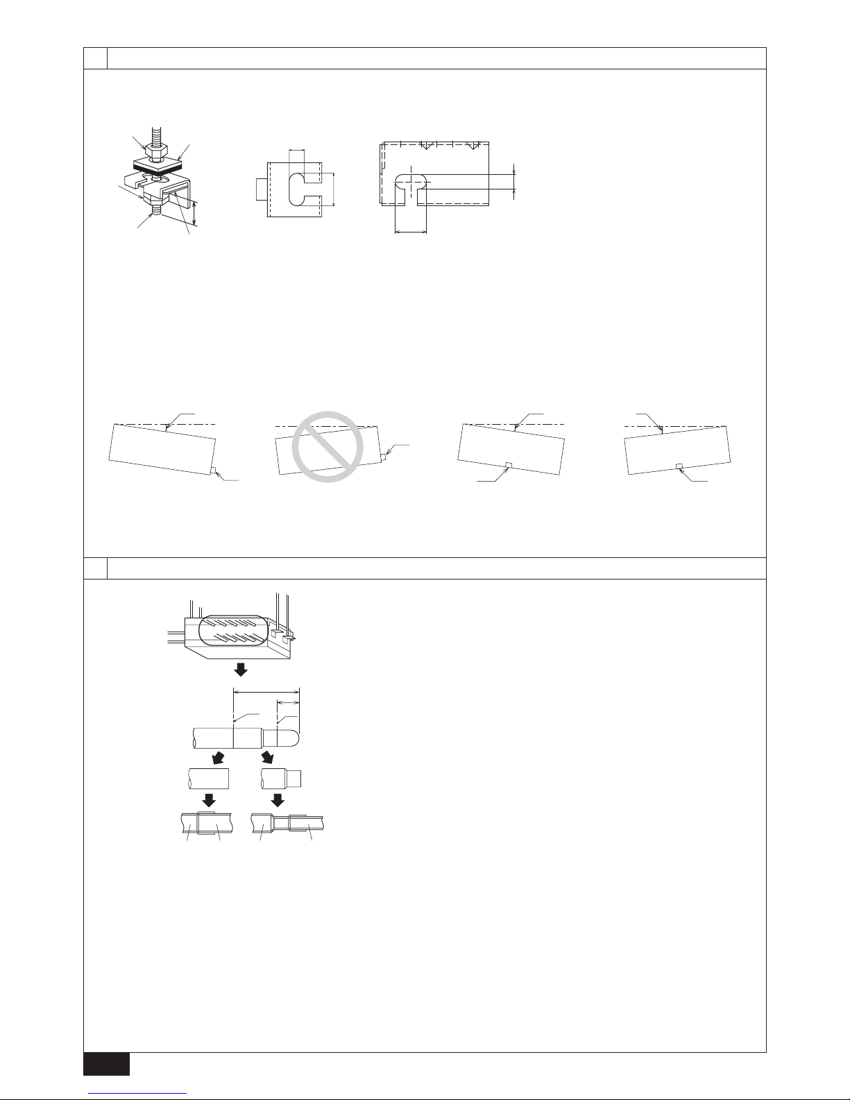
5. Be sure to have pipe expansion of indoor unit connecting port by cutting the
piping at the cutting point which depends on the indoor unit capacity.
6. Restriction on installing the 2-Branch Joint Pipe CMY-R101/102S-G on the
low-pressure piping
- Regarding the 2-Branch Joint Pipe on the low-pressure piping, A and B
must be installed horizontally, and C must be installed upward higher than
the horizontal plane of A and B.
7. Restriction on installing the 2-Branch Joint Pipe CMY-R201/202/203/204/
205S-G on the high-pressure piping, low-pressure piping, and liquid piping.
- Regarding the 2-Branch Joint Pipe on the high-pressure/low-pressure/liquid
piping, A and B must be installed horizontally, and C must be installed
upward higher than the horizontal plane of A and B.
Note:
Remove burr after cutting the piping to prevent entering the piping.
Check that there is no crack at the pipe expansion part.
[Fig. 4.1.1] (P.4)
Ⓐ Indoor unit connecting port
Ⓑ Cutting point : ø9.52 (Liquid side) or ø15.88 (Gas side)
(Indoor unit model : above P50)
Ⓒ Cutting point : ø6.35 (Liquid side) or ø12.7 (Gas side)
(Indoor unit model : P50 or below)
Ⓓ Cut the piping at the cutting point
Ⓔ Have pipe expansion of indoor unit connecting port
Ⓕ Field pipe
8. Be sure to use non-oxidative brazing where necessary. If you do not use
non-oxidative brazing, it may clog the pipes.
While under a nitrogen purge, braze the indoor unit connecting port before
brazing the outdoor unit connecting port of BC controller.
When brazing the indoor unit connecting port, supply a nitrogen gas into the
outdoor unit connecting port of BC controller.
When brazing the outdoor unit connecting port of BC controller, supply a
nitrogen gas into the pipe between the outdoor unit and BC controller.
9. After completing pipe connection, support the pipes to ensure that load is
not imparted to the BC controller’s end connections (particularly to the gas
pipes of indoor units).
Warning :
When installing and moving the unit, do not charge it with refrigerant other
than the refrigerant (R410A) specied on the unit.
- Mixing of a different refrigerant, air, etc. may cause the refrigerant cycle to malfunction and result in severe damage.
Caution:
• Use refrigerant piping made of phosphorus deoxidized copper and copper
alloy seamless pipes and tubes. In addition, be sure that the inner and
outer surfaces of the pipes are clean and free of hazardous sulphur, oxides,
dust/dirt, shaving particles, oils, moisture, or any other contaminant.
- R410A is a high-pressure refrigerant and can cause the existing piping to burst.
• Store the piping to be used during installation indoors and keep both ends
of the piping sealed until just before brazing. (Store elbows and other
joints in a plastic bag.)
- If dust, dirt, or water enters the refrigerant cycle, deterioration of the oil and
compressor failure may result.
• Apply a small amount of ester oil, ether oil, or alkyl benzene to ares. (for
indoor unit)
- Inltration of a large amount of mineral oil may cause the refrigerant oil to
deteriorate.
• Do not vent R410A into the atmosphere.
To main BC controller
B
C
To sub BC controller
To outdoor unit
A
To sub BC controller
B
C
To sub BC controller
To main BC controller
A
Page 14
GB
14
1. Size of BC controller’s end connection piping
Available connection (✔ mark : available)
Model name
(MAIN)BC
CONTROLLER
CMB-P104V-J
CMB-P106V-J
CMB-P108V-J
CMB-P1012V-J
CMB-P1016V-J
CMB-P108V-JA
CMB-P1012V-JA
CMB-P1016V-JA
CMB-P1016V-KA CMB-P108V-JA
CMB-P1012V-JA
CMB-P1016V-JA
CMB-P1016V-KA
SUB BC
CONTROLLER
No available No available No available
CMB-P104V-KB
(Qty. 1 to 11)
CMB-P104V-KB
(Qty. 1 to 11)
Outdoor unit
Capacity
(E)P200 - 350
✔ ✔ ✔ ✔ ✔
(E)P351 - 900
✔ ✔ ✔ ✔
(E)P901 - 1100
✔ ✔
BC controller / Main BC controller Sub BC controller
Unit model
High pressure side*1
Low pressure side*1
Total capacity of
indoor units
High pressure (gas)
side *2
Low pressure (gas)
side *2
Liquid side *2
Outdoor (Heat source) unit side
PURY-(E)P200
PQRY-P200
ø15.88 (Brazing) ø19.05 (Brazing) 200 or less ø15.88 (Brazing) ø19.05 (Brazing)
ø9.52 (Brazing)
PURY-(E)P250
PQRY-P250
ø19.05 (Brazing)
ø22.2 (Brazing)
201 - 300
ø19.05 (Brazing)
ø22.2 (Brazing)
PURY-(E)P300
PQRY-P300
301 - 350
ø28.58 (Brazing)
ø12.7 (Brazing)
PURY-(E)P350
ø28.58 (Brazing)
351 - 400
ø22.2 (Brazing)
PQRY-P350
ø22.2 (Brazing)
401 - 600
ø15.88 (Brazing)
PURY-(E)P400
PQRY-P400
601 - 650
ø28.58 (Brazing)
PURY-(E)P450
PQRY-P450
651 - 800 ø34.93 (Brazing)
ø19.05 (Brazing)PURY-(E)P550
PQRY-P550
ø22.2*2 (Brazing)
801 - 1000
ø41.28 (Brazing)
PURY-(E)P600 1001 - ø34.93 (Brazing)
PQRY-P600 ø34.93 (Brazing)
*1. The maximum total capacity of indoor units that can be connected to each Sub BC
controller is P350.
*2. Use separately sold parts if the pipe diameter is not appropriate.
PURY-(E)P650
ø28.58 (Brazing)
ø28.58 (Brazing)
PURY-(E)P700
PQRY-P700
ø34.93 (Brazing)
PURY-(E)P750
PQRY-P750
PURY-(E)P800
PQRY-P800
PURY-(E)P850
PQRY-P850
ø41.28 (Brazing)
PURY-(E)P900
PQRY-P900
PURY-(E)P950
PURY-(E)P1000
PURY-(E)P1050
ø34.93 (Brazing)
PURY-(E)P1100
*1. Use separately sold parts if the pipe diameter is not appropriate.
*2. If the length of high-pressure pipe A exceeds 65 m (213 ft), use the
ø28.58 (ø1-1/8) pipes for all pipes after 65 m (213 ft).
[Fig. 4.1.2] (P.5)
Ⓐ To outdoor unit (Main BC controller)
Ⓑ End connection (brazing)
Ⓒ BC controller (Main BC controller / Sub BC controller)
Ⓓ Indoor unit
Ⓔ P50 or below
Ⓕ Combined piping kit (Model name: CMY-R160-J1)
Ⓖ Twinning pipe (Model name: CMY-Y102SS-G2, CMY-Y102LS-G2)
Ⓗ Up to three units for 1 branch hole; total capacity: 80 or below
(but same in cooling/heating mode)
The size of BC controller’s branch piping is for 63 to 140 type indoor units.
Therefore, if you want to connect indoor units other than the above, connect
piping following the procedures below.
*1. For connecting 15 to 50 model indoor units
Have pipe expansion of indoor unit connecting port by cutting the piping at the
cutting point which depends on the indoor unit capacity.
Note:
Remove burr after cutting the piping to prevent entering the piping.
Check that there is no crack at the pipe expansion part.
*2. To connect a unit with a capacity of 81 or above.
After combining two branches using an optionally available piping kit
(CMY-R160-J1), connect indoor units.
*3. Connection of plural indoor units with one connection (or joint pipe)
• Total capacity of connectable indoor units: 80 or below (250 or below with joint
pipe)
• Number of connectable indoor units: Maximum 3 Sets
• Twinning pipe: Use the twinning pipe for CITY MULTI Y Series (CMY-Y102SS-
G2, CMY-Y102LS-G2)
• Selection of refrigerant piping
Select the size according to the total capacity of indoor units to be installed
downstream.
Total capacity of indoor units Liquid line Gas line
140 or below
ø9.52
ø15.88
141 to 200 ø19.05
201 to 250 ø22.2
Note:
Be sure to use non-oxidative brazing.
Page 15
GB
15
4.2. Refrigerant piping work
After connecting the refrigerant pipes of all indoor and outdoor units with the
outdoor units’ stop valves remained fully closed, evacuate vacuum from the
outdoor units’ stop valve service ports.
After completing the above, open the outdoor units’ stop valves. This connects
the refrigerant circuit (between outdoor and BC controller) completely.
How to handle stop valves is described on each outdoor unit.
Notes:
• After pipe connection, be sure to check that there is no gas leakage, using
a leak detector or soap-and-water solution.
• Before brazing the refrigerant piping, always wrap the piping on the main
body, and the thermal insulation piping, with damp cloths to prevent heat
shrinkage and burning the thermal insulation tubing. Take care to ensure
that the ame does not come into contact with the main body itself.
• Do not use leak-detection additives.
Warning:
Do not mix anything other than the specied refrigerant (R410A) into the
refrigerating cycle when installing or moving. Mixing air may cause the
refrigerating cycle to reach abnormally high temperature, resulting in burst
pipes.
Caution:
Cut the tip of the outdoor unit piping, remove the gas, and then remove the
brazed cap.
[Fig. 4.2.1] (P.5)
Ⓐ Cut here
Ⓑ Remove brazed cap
4.3. Insulating refrigerant pipes
Be sure to add insulation work to refrigerant piping by covering high-pressure
pipe and low-pressure pipe separately with enough thickness heat-resistant
polyethylene, so that no gap is observed in the joint between indoor unit and
insulating material, and insulating materials themselves. When insulation work is
insufcient, there is a possibility of condensation drip, etc. Pay special attention
to insulation work in the ceiling plenum.
[Fig. 4.3.1] (P.5)
Ⓐ Insulating material for pipes (not supplied)
Ⓑ Bind here using band or tape.
Ⓒ Do not leave any opening.
Ⓓ Lap margin: more than 40 mm
Ⓔ Insulating material (not supplied)
Ⓕ Unit side insulating material
Ⓖ Minimum 30 mm
• Insulation materials for the pipes to be added on site must meet the following
specications:
Outdoor unit
-BC controller
High-pressure pipe: 10 mm or more
Low-pressure pipe: 20 mm or more
BC controller
-indoor unit
Pipe size 6.35 to 25.4 mm: 10 mm or more
Pipe size 28.58 to 41.28 mm: 15 mm or more
Temperature resistance 100°C or above
• Installation of pipes in a high-temperature high-humidity environment, such as
the top oor of a building, may require the use of insulation materials thicker
than the ones specied in the chart above.
• When certain specications presented by the client must be met, ensure that
they also meet the specications on the chart above.
• The brazed connections must be covered with the insulations, its cutting
surface upward and fastened with the bands.
• Insulate the pipe that protrudes from the BC controller if the pipe is not going
to be connected to other pipes.
[Fig. 4.3.2] (P.5)
Ⓐ Insulating material (not supplied)
Ⓑ Bind here using band or tape.
4.4. Drain piping work
1. Drain piping work
• Tilt the drain pan so that the water will ow toward the drain socket.
[Fig. 4.4.1] (P.5)
① Unscrew the two screws that are holding the side panel on the right
side of the control box.
② Tilt the drain pan.
③ Screw down the screws with the drain pan tilted.
• Ensure that the drain piping is downward (pitch of more than 1/100) to the
outdoor (discharge) side. Do not provide any trap or irregularity on the way.
• Ensure that any cross-wise drain piping is less than 20 m (excluding the
difference of elevation). If the drain piping is long, provide metal braces to
prevent it from waving. Never provide any air vent pipe. Otherwise drain may
be ejected.
• Use a hard vinyl chloride pipe VP-25 (with an external diameter of 32 mm) for
drain piping.
• Ensure that collected pipes are 10 cm lower than the unit body’s drain port.
• Do not provide any odor trap at the drain discharge port.
• Put the end of the drain piping in a position where no odor is generated.
• Do not put the end of the drain piping in any drain where ionic gases are
generated.
[Fig. 4.4.2] (P.6)
○ Correct piping
× Wrong piping
Ⓐ Insulation (9 mm or more)
Ⓑ Downward slope (1/100 or more)
Ⓒ Support metal
Ⓚ Air bleeder
Ⓛ Raised
Ⓜ Odor trap
Grouped piping
Ⓓ O.D. ø32 PVC TUBE
Ⓔ Make it as large as possible. About 10 cm.
Ⓕ Indoor unit
Ⓖ Make the piping size large for grouped piping.
Ⓗ Downward slope (1/100 or more)
Ⓘ O.D. ø38 PVC TUBE for grouped piping. (9 mm or more insulation)
Ⓙ BC controller
1. Insert the drain hose (accessory) into the drain port (insertion margin: 32
mm). (The drain hose must not be bent more than 45° to prevent the hose
from breaking or clogging.)
(Attach the hose with glue, and x it with the band (small, supplied).)
2. Attach the drain pipe (O.D. ø32 PVC TUBE PV-25, not supplied).
(Attach the pipe with glue, and x it with the band (small, supplied).)
3. Perform insulation work on the drain pipe (O.D. ø32 PVC TUBE PV-25) and
on the socket (including elbow).
4. Check the drainage.
5. Attach the insulating material, and x it with the band (large, supplied) to
insulate the drain port.
[Fig. 4.4.3] (P.6)
Ⓐ BC controller
Ⓑ Tie band (supplied)
Ⓒ Visible part
Ⓓ Insertion margin
Ⓔ Drain hose (supplied)
Ⓕ Drain pipe (O.D. ø32 PVC TUBE, not supplied)
Ⓖ Insulating material (not supplied)
Ⓗ Tie band (supplied)
2. Discharge test
After completing drain piping work, open the BC controller panel, and test drain
discharge using a small amount of water. Also, check to see that there is no
water leakage from the connections.
3. Insulating drain pipes
Provide sufcient insulation to the drain pipes just as for refrigerant pipes.
Caution:
Be sure to provide drain piping with heat insulation in order to prevent
excess condensation. Without drain piping, water may leak from the unit
causing damage to your property.
Page 16
GB
16
5. Electrical work
► Consult all related regulations and power companies beforehand.
Warning:
Electrical work should be handled by qualied electrical engineers in
accordance with all related regulations and attached instruction manuals.
Special circuits should also be used. If there is a lack of power capacity or
a deciency in electrical work, it may cause a risk of electric shock or re.
► Connect all wires securely.
• Fix power source wiring to control box by using buffer bushing for tensile
force (PG connection or the like).
[Fig. 5.0.1] (P.6)
Ⓐ Control box
Ⓑ Power source wiring
Ⓒ ø21 hole (closed rubber bushing)
Ⓓ Transmission wiring
► Never connect the power cable to the terminal board for control cables.
(Otherwise it may be broken.)
► Be sure to wire between the control wire terminal boards for indoor
unit, outdoor unit and BC controller.
Use non-polarized 2-wire as transmission cables.
Use 2-core shielding cables (CVVS, CPEVS) of more than 1.25 mm
2
in diameter
as transmission cables.
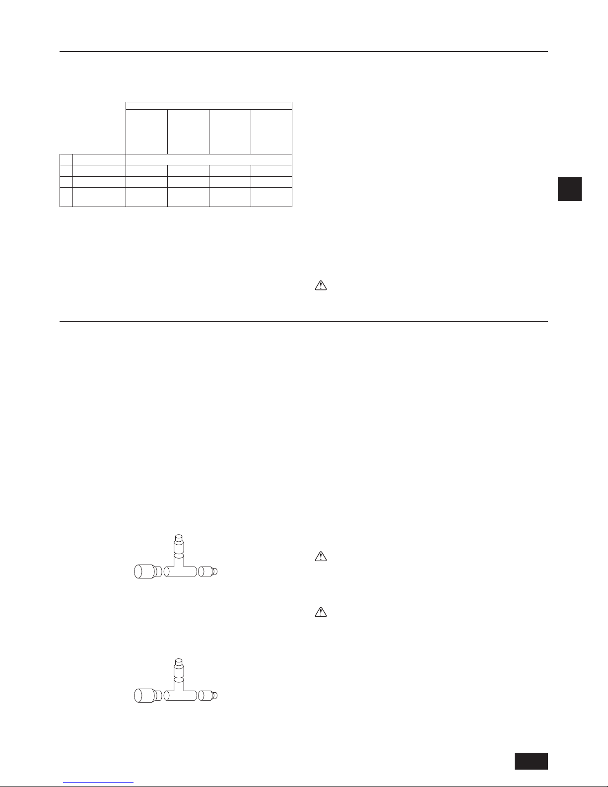
The switch capacity of the main power to BC controllers and the wire size are as
follows:
Switch (A)
Molded case
circuit breaker
Earth leakage
breaker
Wire size
Capacity Fuse
16 16 20 A
20 A 30 mA
0.1 s or less
1.5 mm
2
• For other detailed information, refer to the outdoor unit installation manual.
• Power supply cords of appliances shall not be lighter than design 245 IEC 53
or 227 IEC 53.
• A switch with at least 3 mm contact separation in each pole shall be provided
by the Air conditioner installation.
Caution:
Do not use anything other than the correct capacity fuse and breaker.
Using fuse, conductor or copper wire with too large capacity may cause a
risk of malfunction or re.
Ensure that the outdoor units are put to the ground. Do not connect the
earth cable to any gas pipe, water pipe, lightening rod or telephone earth
cable. Incomplete grounding may cause a risk of electric shock.
6. Setting addresses and operating units
The address switch of each BC controller is set to “000” when shipped from the
factory.
• Set the address switch to 1 + the address of the outdoor (heat source) unit.
► The BC controller address should generally be set to 1 + the address of
the outdoor (heat source) unit. However, if this would result in it having
the same address as another outdoor unit, set the address between 51
and 100, making sure that it is different from the address of other BC
controllers.
• Please refer to the outdoor (heat source) unit installation manual.
7. Test run
Before commencing a test run please check the following:
► After installing, piping and wiring the indoor units and BC controllers,
check to see again that there is no refrigerant leakage and no slack on
power and control cables.
► Use a 500 V megger to check that there is an insulation resistance of
more than 1.0 MΩ between the power terminal block and the ground. If
it is less than 1.0 MΩ, do not operate the unit.
Caution:
Never measure the insulation resistance of the terminal block for any
control cables.
Page 17
D
17
1. Sicherheitsvorkehrungen
1.1. Vor Beginn der Installations- und Elektroarbeiten
► Lesen Sie vor dem Installieren des Geräts unbedingt alle im
Abschnitt „Sicherheitsvorkehrungen“ beschriebene Hinweise.
► Der Abschnitt „Sicherheitsvorkehrungen“ verweist auf sehr
wichtige Sicherheitsaspekte. Achten Sie auf ihre Befolgung.
In diesem Text verwendete Symbole
Warnung:
Beschreibt Vorkehrungen, die getroffen werden sollten, um einer Verlet-
zungsoder Lebensgefahr des Anwenders vorzubeugen.
Achtung:
Beschreibt Vorkehrungen, die getroffen werden sollten, um einer Beschä-
digung des Geräts vorzubeugen.
In den Illustrationen verwendete Symbole
: Verweist auf einen Vorgang, der vermieden werden muss.
: Verweist auf wichtige Anleitungen, die befolgt werden müssen.
: Verweist auf ein Teil, das geerdet sein muss.
: Stromschlaggefahr. (Dieses Symbol ist am Etikett des Hauptgeräts
angebracht.) <Farbe: Gelb>
Warnung:
Lesen Sie die am Hauptgerät angebrachten Etiketten sorgfältig.
ACHTUNG HOCHSPANNUNG:
• Die Steuerung enthält unter Hochspannung stehende Teile.
• Achten Sie darauf, dass die Frontverkleidung der Steuerung beim Öffnen
oder Schließen nicht mit internen Komponenten in Kontakt kommt.
• Schalten Sie vor der Inspektion des Inneren der Steuerung die Stromversorgung aus, lassen Sie das Gerät mindestens 10 Minuten ausgeschaltet.
Warnung:
• Ein beschädigtes Netzkabel muss vom Hersteller oder dem zugelassenen
Kundendienst oder einer ähnlich qualizierten Person ausgewechselt
werden, um Gefahren vorzubeugen.
• Das Gerät ist nicht für die Verwendung durch Personen (einschließlich
Kinder) mit eingeschränkten physischen, sensorischen oder psychischen
Fähigkeiten bzw. ohne jegliche Erfahrung oder Wissen vorgesehen, es sie
denn, sie stehen unter Aufsicht oder wurden in die Verwendung des Gerätes durch eine Person, die für ihre Sicherheit verantwortlich ist, eingewiesen.
• Dieses Gerät ist für die Verwendung durch Experten oder geschulten
Benutzern in Geschäften, in der Leichtindustrie und in landwirtschaftlichen
Betrieben oder für kommerzielle Zwecke durch Laien vorgesehen.
• Bitte verwenden Sie nur das in den mit dem Gerät mitgelieferten Handbü-
chern und auf dem Typenschild angegebene Kältemittel.
- Andernfalls können das Gerät oder die Rohrleitungen platzen, oder es kann zu Explosionen
oder Feuer während des Betriebes oder bei der Entsorgung des Gerätes kommen.
- Es ist auch möglich, dass dies zu einer Verletzung der geltenden Gesetze führt.
- MITSUBISHI ELECTRIC CORPORATION kann nicht für Störungen oder
Unfälle verantwortlich gemacht werden, die durch Verwendung eines
falschen Kältemittels entstehen.
• Beauftragen Sie den Händler oder eine autorisierte Fachkraft mit der Installation des Klimageräts.
- Eine unsachgemäße Installation durch den Anwender kann in Wasserleckage, Stromschlag oder Feuer resultieren.
• Installieren Sie das Gerät an einem Ort mit einer für sein Gewicht ausreichenden Tragkraft.
- Andernfalls könnte das Gerät herunterfallen und Verletzungen oder
Geräteschäden verursachen.
• Verwenden Sie zur Verkabelung die angegebenen Kabel. Schließen Sie
sie sicher an, so dass externe auf das Kabel aufgebrachte Kräfte nicht auf
die Anschlüsse übertragen werden.
- Bei einem inkorrekten Anschluss oder Befestigen kann Hitze entstehen und
ein Brand verursacht werden.
• Treffen Sie Vorkehrungen zum Schutz vor starkem Wind und Erdbeben
und installieren Sie das Gerät am angegebenen Ort.
- Eine unsachgemäße Installation könnte im Herunterfallen des Geräts und
in Verletzungen oder Geräteschäden resultieren.
• Verwenden Sie ausschließlich von Mitsubishi Electric speziziertes Zubehör.
- Beauftragen Sie eine autorisierte Fachkraft mit der Installation des
Zubehörs. Eine unsachgemäße Installation durch den Anwender kann in
Wasserleckage, Stromschlag oder Feuer resultieren.
• Versuchen Sie nie, das Gerät zu reparieren. Wenden Sie sich zur Reparatur des Klimageräts stets an den Händler.
- Eine unsachgemäße Reparatur des Geräts kann in Wasserleckage,
Stromschlag oder Feuer resultieren.
• Berühren Sie die Kältemittelleitungen nicht.
- Unsachgemäßer Gebrauch kann zu Verletzungen führen.
• Tragen Sie bei der Verwendung dieses Geräts stets geeignete Schutzausrüstung.
Z. B.: Handschuhe, vollständiger Armschutz (Overall) und Schutzbrille.
- Unsachgemäßer Gebrauch kann zu Verletzungen führen.
• Lüften Sie den Raum, falls während der Installationsarbeiten Kältegas austritt.
- Wenn das Kältegas mit einer offenen Flamme in Kontakt kommt, werden
giftige Gase freigesetzt.
• Installieren Sie das Klimagerät gemäß dieses Installationshandbuchs.
- Eine unsachgemäße Installation des Geräts kann in Wasserleckage,
Stromschlag oder Feuer resultieren.
• Alle Elektroarbeiten müssen von einem lizenzierten Elektriker gemäß dem
„Technischen Standard für Elektroanlagen“ und den „Verkabelungsvorschriften für Innenräume“ sowie den in diesem Handbuch gegebenen Anleitungen ausgeführt werden.
- Des Weiteren ist eine geeignete Stromversorgung zu verwenden. Eine
unzureichende Kapazität der Stromversorgung oder inkorrekt ausgeführte
Elektroarbeiten können in Stromschlag oder Feuer resultieren.
• Elektrische Teile stets von Wasser (Waschwasser usw.) fernhalten.
- Dies kann zu Stromschlägen, Feuer- oder Rauchentwicklung führen.
• Installieren Sie die Abdeckung des Schaltkastens sicher.
- Wenn die Abdeckung der Elektroanschlüsse nicht sachgemäß angebracht
wurde, kann Staub oder Wasser in die Außenanlage eindringen und Brand
oder Stromschlag verursachen.
• Wenn das Klimagerät installiert oder an einen anderen Ort transportiert
wird, darf es mit keinem anderen als dem am Gerät angegebenen Kältemittel gefüllt werden.
- Falls ein anderes Kältemittel oder Luft mit dem Originalkältemittel gemischt
wird, kann dies in einer Funktionsstörung des Kältemittelkreislaufs oder
einer Beschädigung des Geräts resultieren.
• Bei der Installation des Klimageräts in einem kleinen Raum müssen Vorkeh-
rungen getroffen werden, um ein Überschreiten der Sicherheitsgrenze der
Kältemittelkonzentration im Fall einer Leckage von Kältemittel zu verhindern.
- Holen Sie den Rat des Händlers bezüglich angemessener Maßnahmen zur
Verhinderung der Überschreitung dieser Sicherheitsgrenze ein. Bei einer
Leckage von Kältemittel und einem Überschreiten der Sicherheitsgrenze
besteht im Raum Gefahr in Folge von Sauerstoffmangel.
• Holen Sie beim Transportieren oder der Neuinstallation des Klimageräts
den Rat des Händlers oder einer autorisierten Fachkraft ein.
- Eine unsachgemäße Installation des Klimageräts kann in Wasserleckage,
Stromschlag oder Feuer resultieren.
• Überzeugen Sie sich nach Abschluss der Installationsarbeiten, dass kein
Kältegas austritt.
- Falls Kältegas austritt und mit einem Heizlüfter, Herd, Ofen oder einer anderen
Wärmequelle in Kontakt kommt, können giftige Gase freigesetzt werden.
• Rekonstruieren oder verändern Sie die Schutzvorrichtungen nicht.
- Falls der Druckschalter, Thermoschalter oder eine andere Schutzvorrichtung kurzgeschlossen oder gewaltsam bedient wird oder andere als von
Mitsubishi Electric angegebene Teile verwendet werden, besteht Brandoder
Explosionsgefahr.
• Holen Sie zur Entsorgung dieses Produkts den Rat Ihres Händlers ein.
• Der Installateur und Systemspezialist gewährleistet die Leckagesicherheit
im Einklang mit den örtlich geltenden Vorschriften bzw. Normen.
- Falls keine örtlich geltenden Vorschriften verfügbar sind, treffen die Maßangaben für die Kabellitzen und die Kapazitäten des Hauptstromschalters zu.
• Tragen Sie insbesondere dem Installationsort wie zum Beispiel einem
Keller usw. wo sich Kältegas ansammeln kann Rechnung, da Kältemittel
schwerer als Luft ist.
• Kinder sollten unter Aufsicht stehen, damit gewährleistet wird, dass sie
nicht mit dem Gerät spielen.
Inhalt
1. Sicherheitsvorkehrungen ............................................................................17
1.1. Vor Beginn der Installations- und Elektroarbeiten ..................... 17
1.2. Vorkehrungen für Geräte, die R410A Kältemittel verwenden ...18
1.3. Vor der Installation .................................................................... 18
1.4.
Vor Beginn der Installations- (Standortwechsel) und Elektroarbeiten
....18
1.5. Vor dem Start des Testbetriebs ................................................. 18
2. Wahl eines Aufstellortes ............................................................................. 19
2.1. Produktinformationen ................................................................ 19
2.2. Aufstellort .................................................................................. 19
2.3. Freiraum für Installation und Bedienung ................................... 19
2.4. Überprüfung des Aufstellortes .................................................. 20
3. Installation der BC-Steuerung .................................................................... 23
3.1.
Überprüfung des mit der BC-Steuerung gelieferten Zubehörs
.... 23
3.2. Installation der BC-Steuerungen ............................................... 23
4. Anschluß der Kältemittelund Abwasserrohrleitungen ................................. 23
4.1. Anschluß der Kältemittelrohrleitungen ...................................... 23
4.2. Arbeiten an der Kältemittelrohrleitung ...................................... 25
4.3. Isolieren der Kältemittelrohrleitungen ....................................... 25
4.4. Arbeiten an der Auslaufrohrleitung ...........................................25
5. Elektroarbeiten ........................................................................................... 26
6. Einstellung der Adressen und Betrieb der Anlage ......................................26
7. Testlauf ....................................................................................................... 26
Page 18
D
18
1.2. Vorkehrungen für Geräte, die R410A
Kältemittel verwenden
Warnung:
• Bitte verwenden Sie nur das in den mit dem Gerät mitgelieferten Handbüchern und auf dem Typenschild angegebene Kältemittel.
- Andernfalls können das Gerät oder die Rohrleitungen platzen, oder es kann
zu Explosionen oder Feuer während des Betriebes oder bei der Entsorgung
des Gerätes kommen.
- Es ist auch möglich, dass dies zu einer Verletzung der geltenden Gesetze führt.
- MITSUBISHI ELECTRIC CORPORATION kann nicht für Störungen oder
Unfälle verantwortlich gemacht werden, die durch Verwendung eines
falschen Kältemittels entstehen.
Achtung:
• Verwenden Sie keine bereits vorhandenen Kältemittelleitungen.
- In den vorhandenen Leitungen verbliebenes altes Kältemittel und Kühlöl kann einen hohen
Chloranteil aufweisen und einen Güteverlust des Kühlöls des neuen Geräts verursachen.
- R410A ist ein Hochdruckkältemittel und kann vorhandene Leitungen zum Platzen bringen.
• Verwenden Sie Kältemittelleitungen aus deoxidiertem Phosphorkupfer
sowie nahtlose Kupferlegierungsleitungen und -rohre. Vergewissern Sie
sich des Weiteren, dass die Innen- und Außenächen der Leitungen frei
von gefährlichen Rückständen wie Schwefel, Oxiden, Staub/Schmutz,
Spänen, Ölen, Feuchtigkeit und jeglichen anderen Kontaminierungen sind.
- Kontaminierungsstoffe im Inneren der Kältemittelleitungen können einen
Güteverlust des Kältemittelöls bewirken.
• Lagern Sie die bei der Installation zu verwendenden Rohrleitungen in einem Innenraum
und halten Sie beide Rohrenden bis kurz vor dem Hartlöten verschlossen. (Bewahren
Sie Rohrbögen und andere Verbindungselemente in einem Kunststoffbeutel auf.)
- Wenn Staub, Schmutz oder Wasser in den Kältemittelkreislauf gelangen, kann
dies zu einer Qualitätsminderung des Öls und zu Kompressorstörungen führen.
• Tragen Sie etwas Esteröl, Ätheröl oder Alkylbenzol auf die Rohrmuffen auf. (Innengerät)
- Das Eindringen einer größeren Menge von Mineralöl kann einen Güteverlust des Kältemittelöls verursachen.
• Verwenden Sie üssiges Kältemittel zum Füllen des Systems.
- Wenn das System mit Kältegas gefüllt wird, ändert sich die Zusammensetzung
des Kältemittels im Zylinder und es kann zu einem Leistungsverlust kommen.
• Verwenden Sie kein anderes Kältemittel als R410A.
- Falls ein anderes Kältemittel (R22 usw.) mit R410A gemischt wird, kann das im
Kältemittel enthaltene Chlor einen Güteverlust des Kältemittelöls verursachen.
• Verwenden Sie eine Vakuumpumpe mit Rückschlagventil.
- Aus der Vakuumpumpe könnte Öl in den Kältemittelkreislauf zurückießen
und einen Güteverlust des Kältemittelöls verursachen.
• Verwenden Sie keine der folgenden Hilfsmittel, die in Verbindung mit
herkömmlichen Kältemitteln verwendet werden.
(Messverteiler, Füllschlauch, Gasleckagedetektor, Rückschlagventil,
Kältemittelfüllständer, Kältemittelrückgewinnungsausrüstung)
- Das Mischen von herkömmlichem Kältemittel mit Kältemittelöl kann einen
Güteverlust des R410A-Kältemittels verursachen.
- Das Mischen von Wasser und R410A kann einen Güteverlust des Kältemittelöls verursachen.
- Da R410A vollkommen chlorfrei ist, sprechen für herkömmliche Kältemittel
verwendete Gasleckagesensoren unter Umständen nicht an.
• Verwenden Sie keinen Füllzylinder.
- Die Verwendung eines Füllzylinders kann einen Güteverlust des Kältemittels verursachen.
• Kein Antioxidationsoder Zusatzmittel für Leckentdeckung verwenden.
• Gehen Sie bei der Handhabung der Hilfsmittel besonders sorgfältig vor.
- Falls Staub, Schmutz oder Wasser in den Kältemittelkreislauf eindringt,
kann dies einen Güteverlust des Kältemittels verursachen.
1.3. Vor der Installation
Achtung:
• Installieren Sie das Gerät nicht an Orten, wo brennbares Gas austreten kann.
- Wenn Gas austritt und sich um das Gerät ansammelt, besteht Explosionsgefahr.
• Verwenden Sie das Klimagerät nicht in der Nähe von Lebensmitteln,
Haustieren, Panzen, Präzisionsinstrumenten oder Kunstgegenständen.
- Andernfalls könnte die Qualität der Lebensmittel usw. beeinträchtigt werden.
• Verwenden Sie das Klimagerät nicht in Sonderumgebungen.
- Öl, Dampf, schwefelhaltiger Rauch usw. können eine signikante Leistungsminderung des Klimageräts oder eine Beschädigung seiner Teile verursachen.
• Bei der Installation des Geräts in einem Krankenhaus, einer Kommunikationszentrale oder ähnlichen Orten ist für eine ausreichende Schalldämmung zu sorgen.
- Wechselrichter, private Stromgeneratoren, medizinische Hochfrequenzge-
räte oder Funkanlagen können den Betrieb des Klimageräts beeinträchtigen
oder seinen Ausfall verursachen. Demgegenüber kann sich das Klimagerät
selbst durch Störgeräusche auf solche Geräte oder Anlagen auswirken und
zum Beispiel die medizinische Behandlung oder Bildübertragung stören.
• Installieren Sie das Gerät nicht auf einer Struktur, die Leckage verursachen könnte.
- Bei einer Raumfeuchtigkeit von mehr als 80 % oder einer blockierten Drainageleitung
kann Kondensat aus dem Innengerät oder der BC-Steuerung auslaufen. Treffen Sie
die erforderlichen Drainagevorkehrungen in Verbindung mit der Außeneinheit.
• Achten Sie darauf, das geschäumte Styrol zwischen dem Gerät und der
Ablaufwanne zu entfernen.
1.4. Vor Beginn der Installations- (Standortwechsel) und Elektroarbeiten
Achtung:
• Erden Sie das Gerät.
- Schließen Sie das Erdungskabel nicht an Gasoder Wasserleitungen,
Blitzableiter oder unterirdische Telefonleitungen an. Eine inkorrekte Erdung
kann in Stromschlag resultieren.
• Installieren Sie das Stromkabel so, dass es nicht unter Zugspannung steht.
- Zugkräfte können das Durchreißen des Kabels verursachen sowie in
Wärmeentwicklung und Brandgefahr resultieren.
• Installieren Sie bei Bedarf einen Leckageschutzschalter.
- Falls kein Leckageschutzschalter installiert wird, kann Stromschlaggefahr
bestehen.
• Verwenden Sie Stromkabel mit einer ausreichenden Stromübertragungs-
kapazität und Nennleistung.
- Unterdimensionierte Kabel können Kriechstrom, Wärmeentwicklung und
Brandgefahr bewirken.
• Verwenden Sie nur einen Schutzschalter und eine Sicherung mit der angegebenen Kapazität.
- Ein Schutzschalter oder eine Sicherung mit einer höheren Kapazität oder
deren Ersatz durch einen einfachen Stahl- oder Kupferdraht kann zu einem
generellen Geräteausfall oder Feuer führen.
• Reinigen Sie die Klimageräte nicht mit Wasser.
- Beim Reinigen der Geräte mit Wasser besteht Stromschlaggefahr.
• Achten Sie darauf, dass die Gerätehalterung nicht durch langfristige
Verwendung beschädigt wird.
- Falls Beschädigungen nicht repariert werden, kann das Gerät herunterfallen
und Personenoder Sachschäden verursachen.
• Installieren Sie die Drainageleitung zur Gewährleistung einer ordnungsgemäßen Drainage entsprechend den Anleitungen in diesem Installationshandbuch. Umhüllen Sie die Rohrleitungen zum Vermeiden von Kondensation mit Isoliermaterial.
- Eine inkorrekte Drainage kann in Wasserleckage und der Beschädigung
von Möbeln und anderen Gegenständen resultieren.
• Gehen Sie beim Transport des Produkts sehr sorgfältig vor.
- Das Produkt sollte nicht von nur einer Person getragen werden. Es hat ein
Gewicht von 20 kg.
- An bestimmten Produkten wird PP-Band zur Verpackung verwendet.
Verwenden Sie PP-Band nicht zum Tragen und Transportieren des Geräts.
Dies ist gefährlich.
• Achten Sie auf eine sichere Entsorgung des Verpackungsmaterials.
- Verpackungsmaterial wie Nägel oder andere Metallund Holzteile kann
Stechwunden oder andere Verletzungen verursachen.
- Zerreißen Sie Kunststoffverpackungsbeutel und entsorgen Sie sie so, dass
Kinder nicht mit ihnen spielen können. Kinder, die mit nicht zerrissenen
Kunststoffbeuteln spielen, sind einer Erstickungsgefahr ausgesetzt.
1.5. Vor dem Start des Testbetriebs
Achtung:
• Schalten Sie die Stromversorgung mindestens 12 Stunden vor Betriebsbeginn ein.
- Der Betriebsbeginn unmittelbar nach dem Einschalten des Hauptstromschalters kann zu irreversiblen Beschädigungen interner Komponenten
führen. Lassen Sie den Stromschalter während der Betriebssaison
eingeschaltet.
• Berühren Sie die Schalter nicht mit nassen Fingern.
- Das Berühren eines Schalters mit nassen Fingern kann in einem Stromschlag resultieren.
• Berühren Sie die Kältemittelleitungen nicht während des Betriebs und
unmittelbar danach.
- Die Kältemittelleitungen können während des Betriebs oder unmittelbar
danach je nach dem Zustand des durch die Kältemittelleitungen, den
Kompressor und andere Komponenten des Kältemittelkreislaufs ießenden
Kältemittels heiß oder kalt sein. Das Berühren der Kältemittelleitungen kann
Verbrennungen oder Frostverletzungen Ihrer Hände verursachen.
• Betreiben Sie das Klimagerät nicht bei entfernten Abdeckungen und
Schutzvorrichtungen.
- Es besteht eine Verletzungsgefahr durch sich drehende, heiße oder unter
Hochspannung stehende Teile.
• Schalten Sie die Stromversorgung nicht unmittelbar nach dem Beenden
des Betriebs aus.
- Warten Sie vor dem Ausschalten der Stromversorgung stets mindestens 5
Minuten. Andernfalls besteht die Gefahr, dass Drainagewasser ausießt
oder empndliche Teile mechanisch beschädigt werden.
Page 19
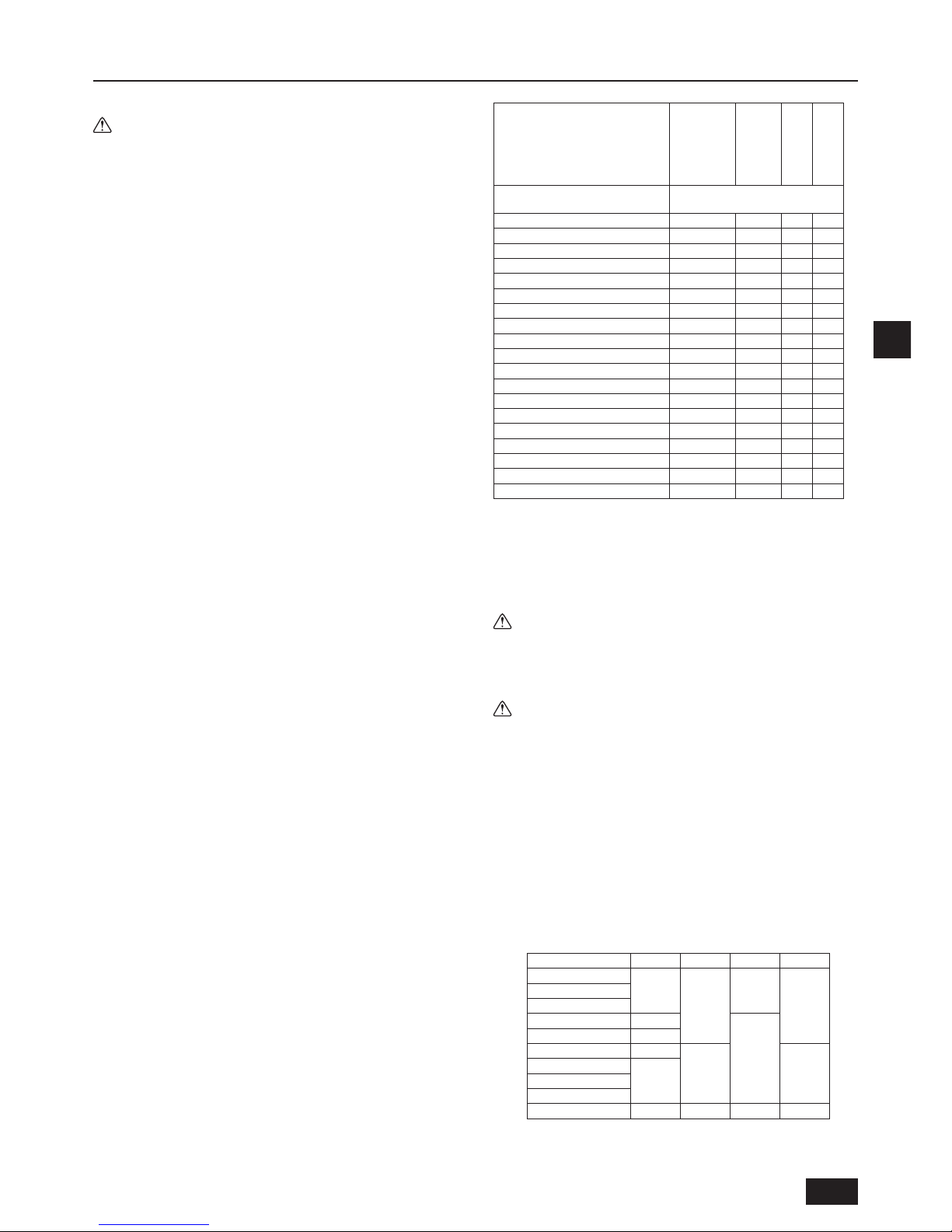
D
19
2. Wahl eines Aufstellortes
2.1. Produktinformationen
Warnung:
• Bitte verwenden Sie nur das in den mit dem Gerät mitgelieferten Handbüchern und auf dem Typenschild angegebene Kältemittel.
- Andernfalls können das Gerät oder die Rohrleitungen platzen, oder es kann
zu Explosionen oder Feuer während des Betriebes oder bei der Entsorgung
des Gerätes kommen.
- Es ist auch möglich, dass dies zu einer Verletzung der geltenden Gesetze
führt.
- MITSUBISHI ELECTRIC CORPORATION kann nicht für Störungen oder
Unfälle verantwortlich gemacht werden, die durch Verwendung eines
falschen Kältemittels entstehen.
• Dieses Gerät verwendet Kältemittel des Typs R410A.
• Rohrleitungen für Systeme, die R410A verwenden, können aufgrund des
konstruktionsbedingten höheren Drucks bei Verwendung von R410A von
denen für Systeme, die herkömmliche Kältemittel verwenden, abweichen.
Weitere Informationen sind im Datenbuch enthalten.
• Einige zur Installation von Systemen, die andere Kältemitteltypen einsetzen,
verwendete Hilfsmittel und Geräte können nicht für Systeme verwendet
werden, die R410A einsetzen. Weitere Informationen sind im Datenbuch
enthalten.
• Verwenden Sie keine vorhandenen Rohrleitungen, da diese Chlor enthalten,
das in herkömmlichen Kühlmaschinenölen und Kältemitteln Verwendung
ndet. Das Chlor beeinträchtigt das im neuen System verwendete Kältemittelöl. Die vorhandenen Rohrleitungen dürfen auch deshalb nicht verwendet
werden, weil der konstruktionsbedingte Druck in Systemen, die R410A
verwenden, höher ist als in Systemen, die andere Kältemittel verwenden, so
dass die vorhandenen Rohrleitungen bersten könnten.
2.2. Aufstellort
• Stellen Sie das Gerät an einem vor Regen geschützten Ort auf. Die
BC-Steuerung ist für die Installation im Hausinneren konstruiert.
• Lassen Sie genügend Platz um das Gerät herum für Wartungen und
Kundendienst.
• Stellen Sie das Gerät nicht so auf, dass die Beschränkung der Leitungslänge
überschritten wird.
• Setzen Sie das Gerät nicht der direkten Wärmestrahlung anderer Hitze
erzeugenden Geräte aus.
• Anlage nicht an einem Ort, der Öldampf ausgesetzt ist, oder neben einer
Maschine aufstellen, die Hochfrequenzen erzeugt. Dadurch können
Brandgefahr oder Fehlfunktionen sowie Kondenswasser entstehen.
• Lassen Sie genug Abstand, damit die Wasserund Kältemittelrohrleitungen
sowie die Elektrokabel problemlos angeschlossen werden können.
• Am Aufstellort dürfen brennbare Gase oder Schwefelgase weder erzeugt,
zugeführt, angesammelt werden noch austreten.
• Sorgen Sie für ein Gefälle der Abussrohrleitung von mindestens 1/100.
• Installieren Sie das Gerät vorschriftsmäßig auf einem soliden tragfähigen
Untergrund.
• Installieren Sie das Gerät nicht an Orten mit viel Dampf. Die Nutzung des
Geräts in feuchten Umgebungen kann zu Kondensation während des
Kühlbetriebes führen.
• Der Betrieb des Geräts in Umgebungen, in denen die Decke, an der das
Gerät angebracht ist, heiß und feucht wird, kann zur Kondensation führen. Da
das Kondenswasser aber in eine Ablaufwanne ießt, verursacht dies
dennoch keine Störung. Obwohl Bereiche, in denen es zur Kondensation
kommt, weiß sein können, hat dies keine Auswirkungen auf den normalen
Betrieb des Geräts.
• Achten Sie darauf, dass das Kondenswasser des Geräts nicht mit Verkabelungen in der Nähe in Kontakt kommt.
1. Zum Aufhängen an der Decke [Fig. 2.2.1] (P.2)
• Sorgen Sie in der Decke für eine Inspektionsöffnung von 450 x 450 mm wie
in [Fig. 2.3.1] (P.2) dargestellt.
• Installieren Sie das Gerät an einem geeigneten Ort (in einer Flurdecke oder
in einem Badezimmer etc.), nicht in viel genutzten Räumlichkeiten. Installieren Sie das Gerät am besten nicht mitten im Raum.
• Bei einer Aufhängung des Gerätes muss eine Belastbarkeit von mindestens
60 kg pro Schraube gewährleistet sein.
• Stellen Sie sicher, dass die BC-Steuerung waagerecht installiert wird.
• Stellen Sie das Gerät an einem Ort auf, an dem der Geräuschpegel der
BC-Steuerung während des Betriebes nicht direkt zu hören ist.
• Stellen Sie das Gerät an einem Ort auf, an dem der Geräuschpegel während
des Betriebes nicht als störend empfunden wird. (Sorgen Sie für einen
Abstand von mindestens 5 m zwischen der Innenanlage und der BC-Steue-
rung, falls ein möglichst geringer Geräuschpegel erwünscht oder nötig ist, wie
z. B. in Hotelzimmern).
Der Schalldruckpegel ist im Folgenden angegeben.
Schalldruckpegel [dB] <A-Skala>
Modellname BC-Steuerung
CMB-P104V-J
CMB-P106V-J
CMB-P108V-J
CMB-P1012V-J
CMB-P1016V-J
CMB-P108V-JA
CMB-P1012V-JA
CMB-P1016V-JA
CMB-P1016V-KA
CMB-P104V-KB
Kapazität des angeschlossenen
Außengeräts (Wärmequelle)
Maximalwert bei normalem oder
Entfrostungsbetrieb
(E)P200 49 53 55 49
(E)P250 49 53 55 49
(E)P300 49 53 55 49
(E)P350 53 55 55 53
(E)P400 - 56 55 (E)P450 - 56 55 (E)P500 - 56 55 (E)P550 - 56 55 (E)P600 - 56 55 (E)P650 - 56 55 (E)P700 - 56 55 (E)P750 - 56 55 (E)P800 - 56 55 (E)P850 - 56 55 (E)P900 - 56 55 (E)P950 - - 55 (E)P1000 - - 55 (E)P1050 - - 55 (E)P1100 - - 55 -
*1. Die Schalldruckpegelwerte wurden in einem schalltoten Raum gemessen.
Der tatsächliche Schalldruckpegel ist aufgrund der Umgebungsgeräusche
und der Schallreexion in der Regel größer als der in einem schalltoten
Raum gemessene.
*2. Die Schalldruckpegelwerte wurden an dem untenstehenden Standort
(1,5 m vom Gerät entfernt) gemessen.
*3. Das Schaltgeräusch des Magnetventils beträgt unabhängig vom
Gerätetyp 56 dB.
Warnung:
Stellen Sie sicher, dass der zur Installation vorgesehene Ort dem Gewicht
des Gerätes standhält.
Bei zu geringer Belastbarkeit kann die Anlage herunterfallen und Verletzungen hervorrufen.
Achtung:
Stellen Sie sicher, dass das Gerät waagerecht installiert wird.
2.3. Freiraum für Installation und Bedienung
1. Beim Herunterhängen von der Decke
(Diese Ansicht zeigt den geringst möglichen Freiraum für die Installation.)
[Fig. 2.3.1] (P.2)
<A> Draufsicht
<B> Vorderansicht
Ⓐ Inspektionsöffnung
Ⓑ Auf der Rohrleitungsseite des Außengeräts
Ⓒ Steuerung
Ⓓ Auf der Rohrleitungsseite des Innengeräts
*1 Abmessungen, mit denen der Rohrleitungsanschluss vor Ort
vorgenommen werden kann
Modellbezeichnung A B C D
CMB-P104V-J
596
-
429
250
CMB-P106V-J
CMB-P108V-J
CMB-P1012V-J 911
573
CMB-P1016V-J 1135
CMB-P108V-JA 911
250 300
CMB-P1012V-JA
1135CMB-P1016V-JA
CMB-P1016V-KA
CMB-P104V-KB 596 - 429 250
Page 20
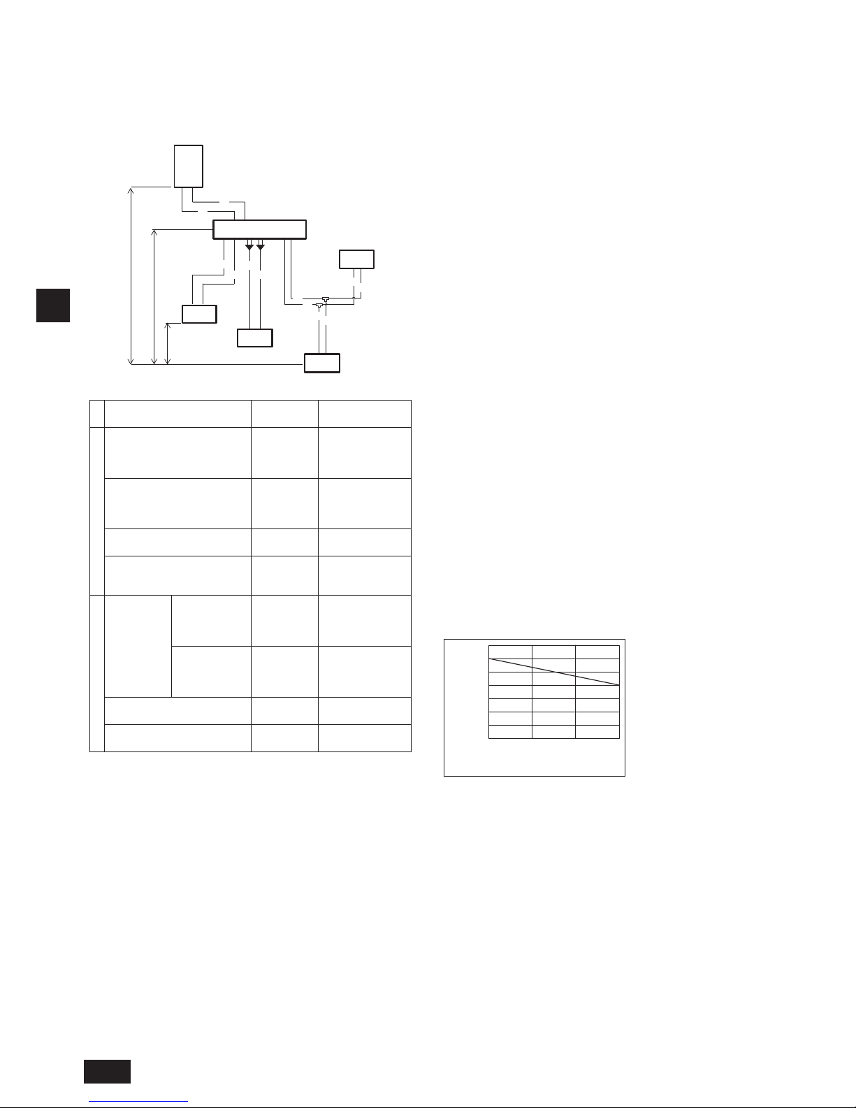
D
20
2.4. Überprüfung des Aufstellortes
Vergewissern, daß die Steigungsdifferenz zwischen Innenund Außenanlage und die Länge der Kältemittelrohrleitung innerhalb nachstehender Grenzwerte liegen.
1. CMB-P104, 106, 108, 1012, 1016V-J (Falls die Außenanlage 14 PS (Modell P350) oder weniger hat und 16 oder weniger Anschlüsse
verwendet werden.)
CMB-P108, 1012, 1016V-JA, CMB-P1016V-KA (Wenn keine Neben-BC-Steuerung angeschlossen ist)
Ⓑ
Ⓓ
A
A
a
a
b
b
Ⓐ
Ⓔ
Ⓓ
Ⓓ
B
B
c
c
d
d
Ⓕ
Ⓖ
H
H1
h1
h2
(Einheit: m)
Position
Rohrleitungs-
abschnitt
Zulässiger Wert
Länge
Gesamte Rohrleitungslänge
„A + B + a + b
+ c + d“
Überschreiten Sie
nicht die Maximallänge für Kältemittelrohrleitungen *1
Längste Rohrleitungslänge „A + B + c“
165 oder weniger
(entspricht einer
Länge von 190 oder
weniger)
Zwischen Außengerät (Wärmequelle) und BC-Steuerung
„A“ 110 oder weniger
Zwischen Innengeräten und
BC-Steuerung
„a“ oder „b“
oder „B + c“
oder „B + d“
60 oder weniger *2
Höhenunterschied
Zwischen
Innen- und
Außengeräten
(Wärmequelle)
Über dem
angeschlossenen
Außengerät
(Wärmequelle)
„H“ 50 oder weniger
Unter dem
angeschlossenen
Außengerät
(Wärmequelle)
„H1“ 40 oder weniger
Zwischen Innengeräten und
BC-Steuerung
„h1“
15 oder weniger
(10 oder weniger *3)
Zwischen Innenanlagen „h2“
30 oder weniger
(20 oder weniger *3)
Ⓐ Außengerät (Wärmequelle)
Ⓑ BC-Steuerung (Haupt)
Ⓒ BC-Steuerung (Neben)
Ⓓ Innengerät (Gesamtkapazität des nachgeschalteten Innengeräts: 15 bis 80)
Ⓔ Innengerät (Gesamtkapazität des nachgeschalteten Innengeräts: 100 bis 250)
Ⓕ Zwillingsrohr (Modellbezeichnung: CMY-R160-J1)
Ⓖ T-Stück
Hinweise:
*1 Siehe „Restrictons on piping length (Grenzwerte der Leitungslänge)“
auf P.3.
*2
Siehe Diagramm „Entfernung zwischen Haupt-BC-Steuerung und weitest
entferntem Innengerät (direkte Verbindung)“. (Wenn jedoch das Modell
P200 oder P250 als Innengerät angeschlossen ist, beträgt der maximal
zulässige Abstand zwischen der BC-Steuerung und dem am weitesten
entfernten Innengerät 40 m.)
*3
Die Werte in den runden Klammern zeigen die vorgeschriebene Maximallänge an, falls die Verbindungsleistung der Innengeräte 200 oder mehr beträgt.
*4 Bei dem System, an welches Innengeräte der Modelle P200 oder höher
angeschlossen werden, dürfen weder Verteileranschlüsse noch
Verteilerabzweigungen verwendet werden.
*5 Innengeräte der Modelle P200 oder P250 dürfen nicht mit Innengeräten
anderer Modellen am selben Anschluss angeschlossen werden.
*6
Bei dem System, an dem die Innengeräte der Modelle P100 bis P140
verwendet werden, müssen die beiden Anschlüsse vor der Installation
verbunden werden. (Stellen Sie DIP SW4-6 an der BC-Steuerung auf ON
(EIN).)
*7 Es ist möglich, die Innengeräte der Modelle P100 bis P140 an nur einen
einzigen Anschluss anzuschließen. (Stellen Sie DIP SW4-6 auf OFF
(AUS).) Beachten Sie, dass die Kühlleistung etwas nachlassen wird. (Die
Werkseinstellung für DIP SW4-6 ist OFF (AUS).)
Wenn nur PEFY-P50/63/71/80VMHS2-E-Geräte angeschlossen werden, die
Dipschalter SW4-1 und SW4-6 an der BC-Steuerung auf ON (EIN) stellen.
*8 Innengeräte, die sich einen Verteileranschluss teilen, können nicht zur
gleichen Zeit in unterschiedlichen Betriebsarten laufen.
*9 Beim Anschluss von PEFY-P50/63/71/80VMHS2-E-Geräten an zwei
Anschlüssen, ein CMY-R160-J1-Anschluss-Set verwenden.
Entfernung zwischen Haupt-BC-Steuerung und
weitest entferntem Innengerät (direkte Verbindung)
Abstand zwischen BC-Steuerung und am
weitesten entferntem Innengerät (m)
15105
20
10
0
0
70
60
50
40
30
Höhendifferenz zwischen BC-Steuerung und
am weitesten entfernter Innenanlage (m)
*10 Zum Anschluss von Innenanlagen des Typs 15 bis 50
Stellen Sie eine Rohrverlängerung des Innengeräteanschlusses durch
Abschneiden der Rohrleitung an der Trennstelle bereit, die je nach Kapazität
des Innengeräts variiert.
Gerät 1
Page 21
D
21
2. CMB-P108, 1012, 1016V-JA, CMB-P1016V-KA (Wenn eine Neben-BC-Steuerung angeschlossen ist)
Ⓓ
a
a
b
b
Ⓐ
Ⓔ
Ⓓ
Ⓓ
B
B
c
c
d
d
Ⓕ
Ⓖ
Ⓐ
Ⓒ
Ⓒ
Ⓒ
Ⓓ
Ⓓ
K
K
L
L
A
C
C
C
D
D
D
E
E
Ⓓ
Ⓒ
G
G
G
J
J
J
M
M
M
F
F
F
e
e
f
f
g
g
j
j
*1
Ⓖ
Ⓓ
h4
H
H1
h1
h1
h1 h3
h2
Ⓑ
E
Ⓖ
Ⓖ
A
(Einheit: m)
Position
Rohrleitungs-
abschnitt
Zulässiger Wert
Länge
Gesamte Rohrleitungslänge
„K + L + A + B + C
+ D + E + F + G + J
+ M + a + b + c + d
+ e + f + g + j“
Überschreiten Sie
nicht die Maximallänge für Kältemittelrohrleitungen *1
Längste Rohrleitungslänge
„K(L) + A + C
+ E + G + J + j“
165 oder weniger
(entspricht einer
Länge von 190 oder
weniger)
Zwischen Außengerät (Wärmequelle) und Haupt-BC-Steuerung
„K(L) + A“ 110 oder weniger
Direkte Verbindung zwischen
Innengeräten und (Haupt- oder
Neben-) BC-Steuerung
„a“ oder „b“
oder „B + c“
oder „B + d“
oder „e“ oder
„f“ oder „g“
oder „j“
60 oder weniger *2
Zwischen Innengeräten und
Haupt-BC-Steuerung über NebenBC-Steuerung
„C + D + e“
oder „C + E +
F + f“ oder „
C
+ E + G + M +
g
“ oder „C + E
+ G + J + j“
90 oder weniger *3
Höhenunterschied
Zwischen
Innen- und
Außengeräten
(Wärmequelle)
Über dem
angeschlossenen
Außengerät
(Wärmequelle)
H 50 oder weniger
Unter dem
angeschlossenen
Außengerät
(Wärmequelle)
H1 40 oder weniger
Zwischen BC-Steuerung (Haupt
und Neben) und Innengerät
h1
15 oder weniger
(10 oder weniger *4)
Zwischen Innenanlagen h2
30 oder weniger
(20 oder weniger *4)
Zwischen BC-Steuerung (Haupt
und Neben) und Neben-BC-Steuerung
h3 15 oder weniger
Zwischen Außengeräten
(Wärmequelle)
h4 0,1 oder weniger
Ⓐ Außengerät (Wärmequelle)
Ⓑ BC-Steuerung (Haupt)
Ⓒ BC-Steuerung (Neben)
Ⓓ Innengerät (Gesamtkapazität des nachgeschalteten Innengeräts: 15 bis 80)
Ⓔ Innengerät (Gesamtkapazität des nachgeschalteten Innengeräts: 100 bis 250)
Ⓕ Zwillingsrohr (Modellbezeichnung: CMY-R160-J1)
Ⓖ T-Stück
Hinweise:
*1 Siehe „Restrictons on piping length (Grenzwerte der Leitungslänge)“
auf P.3.
*2 Siehe Fig. 1.
(Wenn jedoch das Modell P200 oder P250 als Innengerät
angeschlossen ist, beträgt der maximal zulässige Abstand zwischen der
BC-Steuerung und dem am weitesten entfernten Innengerät 40 m.)
*3 Wenn die Rohrleitungslänge oder die Höhendifferenz die in Fig. 1
angegebene Beschränkung überschreitet, eine Neben-BC-Steuerung
an das System anschließen. Die Einschränkungen für ein System mit
einer Neben-BC-Steuerung werden in Fig. 2 dargestellt.
Wenn eine gegebene Systemkonguration innerhalb der schraferten
Fläche in Fig. 2 fällt, die Größe der Hochdruck- und der Flüssigkeitsleitung zwischen der Haupt- und Neben-BC-Steuerung um eine Größe
anheben. Bei Verwendung von Innengeräten der Modelle P32, P40,
P50, P100 oder P125 die Größe des Flüssigkeitszweigrohres zwischen
der Neben-BC-Steuerung und dem Innengerät um eine Größe anheben.
Bei Verwendung von Innengeräten des Typs P140 oder größer können
die in Fig. 1 gezeigten Beschränkungen nicht erweitert werden.
*4 Die Werte in den runden Klammern zeigen die vorgeschriebene
Maximallänge an, falls die Verbindungsleistung der Innengeräte 200
oder mehr beträgt.
*5 Bei dem System, an welches Innengeräte der Modelle P200 oder höher
angeschlossen werden, dürfen weder Verteileranschlüsse noch
Verteilerabzweigungen verwendet werden.
*6 Innengeräte der Modelle P200 oder P250 dürfen nicht mit Innengeräten
anderer Modellen am selben Anschluss angeschlossen werden.
*7 Bei dem System, an dem die Innengeräte der Modelle P100 bis P140
verwendet werden, müssen die beiden Anschlüsse vor der Installation
verbunden werden. (Stellen Sie DIP SW4-6 an der BC-Steuerung auf
ON (EIN).)
*8 Es ist möglich, die Innengeräte der Modelle P100 bis P140 an nur einen
einzigen Anschluss anzuschließen. (Stellen Sie DIP SW4-6 auf OFF
(AUS).) Beachten Sie, dass die Kühlleistung etwas nachlassen wird.
(Die Werkseinstellung für DIP SW4-6 ist OFF (AUS).)
Wenn nur PEFY-P50/63/71/80VMHS2-E-Geräte angeschlossen werden, die
Dipschalter SW4-1 und SW4-6 an der BC-Steuerung auf ON (EIN) stellen.
*9 Innengeräte, die sich einen Verteileranschluss teilen, können nicht zur
gleichen Zeit in unterschiedlichen Betriebsarten laufen.
*10 Beim Anschluss von PEFY-P50/63/71/80VMHS2-E-Geräten an zwei
Anschlüssen, ein CMY-R160-J1-Anschluss-Set verwenden.
*11 Die maximale Gesamtkapazität der Innengeräte, die an jede einzelne
Neben-BC-Steuerung angeschlossen werden können, entspricht P350.
*12 Eine Neben-BC-Steuerung kann bei Ⓑ nicht verwendet werden.
*13 Zum Anschluss von Innenanlagen des Typs 15 bis 50
Stellen Sie eine Rohrverlängerung des Innengeräteanschlusses durch
Abschneiden der Rohrleitung an der Trennstelle bereit, die je nach Kapazität
des Innengeräts variiert.
*14 Es können bis zu 11 Neben-BC-Steuerungen angeschlossen werden.
Gerät 1
Gerät 2
Page 22
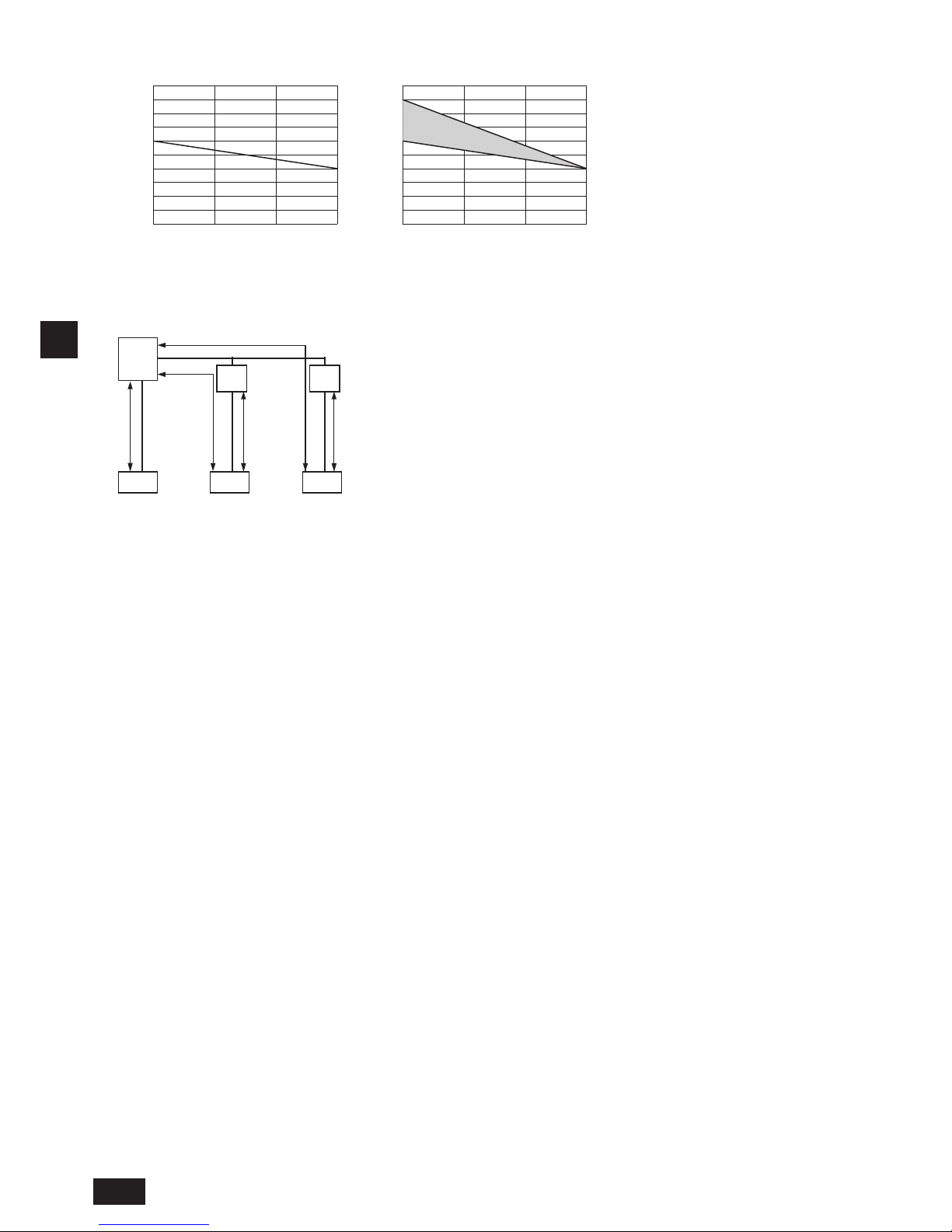
D
22
Rohrleitungslänge und Höhe zwischen Innengerät und BC-Steuerung
Leitungslänge zwischen Haupt- oder
Neben-BC-Steuerung und Innengerät (m)
0 5 10 15
0 5 10 15
10
20
30
40
50
60
70
80
90
100
10
20
30
40
50
60
70
80
90
100
Höhendifferenz zwischen
Haupt-BC-Steuerung und Innengerät (m)
Höhendifferenz zwischen
Haupt-BC-Steuerung und Innengerät (m)
*3 Wenn die Rohrleitungslänge oder die Höhendifferenz die in Fig. 1
angegebene Beschränkung überschreitet, eine Neben-BC-Steuerung
an das System anschließen. Die Einschränkungen für ein System mit
einer Neben-BC-Steuerung werden in Fig. 2 dargestellt.
Wenn eine gegebene Systemkonguration innerhalb der schraferten
Fläche in Fig. 2 fällt, die Größe der Hochdruck- und der Flüssigkeitsleitung zwischen der Haupt- und Neben-BC-Steuerung um eine Größe
anheben. Bei Verwendung von Innengeräten der Modelle P32, P40,
P50, P100 oder P125 die Größe des Flüssigkeitszweigrohres zwischen
der Neben-BC-Steuerung und dem Innengerät um eine Größe anheben.
Bei Verwendung von Innengeräten des Typs P140 oder größer können
die in Fig. 1 gezeigten Beschränkungen nicht erweitert werden.
*3
Leitungslänge zwischen Haupt-BC-Steuerung,
Neben-BC-Steuerung und Innengerät (m)
Fig. 1 Fig. 2
Fig. 1
BC
NebenBC
Fig. 2
Fig. 1
Fig. 2
NebenBC
Fig. 1
InnenanlageInnenanlageInnenanlage
Page 23
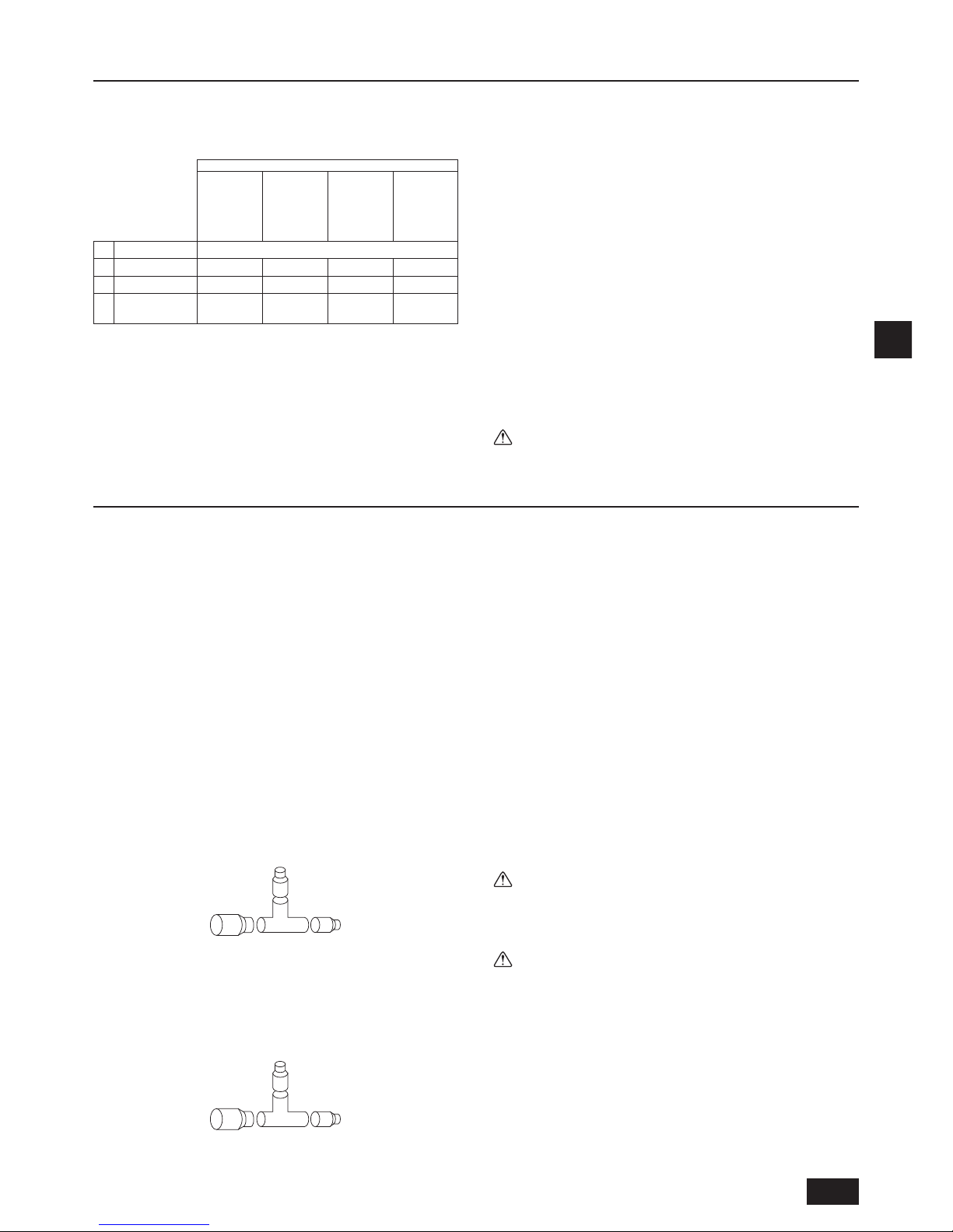
D
23
3. Installation der BC-Steuerung
3.1. Überprüfung des mit der BC-Steuerung
gelieferten Zubehörs
Nachstehende Teile wurden mit jeder BC-Steuerung geliefert.
Modellbezeichnung
CMBP104V-J
P106V-J
P108V-J
P1012V-J
P1016V-J
CMBP108V-JA
P1012V-JA
P1016V-JA
CMBP1016V-KA
CMBP104V-KB
Position Menge
①
Abussleitung 1 1 1 1
②
Befestigungsband
3 3 3 3
③
Unterlegscheibe
zur Montage
2 Sorten
(je 4 Stück)
2 Sorten
(je 4 Stück)
2 Sorten
(je 4 Stück)
2 Sorten
(je 4 Stück)
3.2. Installation der BC-Steuerungen
Anbringen der Aufhängungsbolzen
Nehmen Sie die Installation mit örtlich beschafften Hängebolzen (Gewindestange) entsprechend dem in der Abbildung gzeigten Verfahren vor. Größe der
Aufhängungsbolzen: ø10 (M10-Schraube).
Zum Aufhängen der Anlage diese mit einer Hebevorrichtung anheben und in die
Aufhängungsbolzen einführen.
[Fig. 3.2.1] (P.4)
Ⓐ Mutter (nicht im Lieferumfang enthalten)
Ⓑ Doppelmutter (nicht im Lieferumfang enthalten)
Ⓒ Aufhängungsbolzen mit ø10 (M10-Schraube) (nicht im Lieferumfang enthalten)
Ⓓ Unterlegscheibe (mit Polsterung) (im Lieferumfang enthalten)
* Mit der Polsterung nach unten anbringen.
Ⓔ Mindestens 30 mm
Ⓕ Unterlegscheibe (ohne Polsterung) (im Lieferumfang enthalten)
► Stellen Sie sicher, dass die BC-Steuerung waagerecht unter Zuhilfe-
nahme einer Wasserwaage installiert wird. Wird die Steuerung schräg
installiert, kann Drainagewasser austreten. Neigt sich die Steuerung
muss ihre Position durch Lösen der Befestigungsmuttern an der
Halterung angepasst werden.
► Achten Sie auf ein Gefälle von höchstens 1,5° zur BC-Steuerung hin.
► Die BC-Steuerung nicht direkt auf den Boden legen, da die Ablaufwan-
ne in einer geneigten Position installiert werden muss.
[Fig. 3.2.2] (P.4)
Ⓐ Mit 1,5°
Ⓑ Ablauf
Ⓒ Sicht von der Vorderseite des Steuerungskastens
Achtung:
Stellen Sie sicher, dass das Gerät waagerecht installiert wird.
4. Anschluß der Kältemittelund Abwasserrohrleitungen
4.1. Anschluß der Kältemittelrohrleitungen
1. Schließen Sie die Flüssigkeitsund Gasrohre jedes Innengeräts an dieselben
(richtigen) Endanschlussnummern an, wie im Innengeräteanschlussbereich
jeder BC-Steuerung angegeben. Bei Anschluß an die falschen Endan-
schlußnummern ist kein Normalbetrieb möglich.
2. Modellbezeichnungen der Innenanlagen auf dem Schild am Schaltkasten
der BC-Steuerung (zu Identikationszwecken) auisten. Die Nummern der
Anschlüsse auf der BC-Steuerungsseite und die Adressennummern auf
dem Schild auf der Seite der Innenanlage auisten.
3. Wenn die Anzahl der Anschlussports größer als die Anzahl der anzuschließenden Innengeräte ist, können beliebige Anschlussports verwendet werden.
Versiegeln Sie Endanschlüsse genauso mit Abschlusskappen, wie sie beim
Versand ab Werk versiegelt waren. Wenn keine Versiegelung mit einer
Abschlusskappe erfolgt, tritt Kältemittel aus.
4. Bei Verwendung von CMY-Y102S-G2, CMY-Y102L-G2, CMY-Y202S-G2,
CMY-R201S-G, CMY-R202S-G, CMY-R203S-G, CMY-R204S-G oder
CMY-R205S-G waagerecht anschließen.
5. Stellen Sie sicher, dass die Rohrverlängerung des Innengeräteanschlusses
durch Abschneiden der Rohrleitung an der Trennstelle erfolgt, die je nach
Kapazität des Innengeräts variiert.
6. Einschränkung bei der Installation des T-Stücks CMY-R101/102S-G auf den
Niederdruckrohrleitungen
- A und B müssen waagrecht am T-Stück der Niederdruckrohrleitung
angeschlossen werden. C muss nach oben installiert werden und höher
liegen als die horizontale Ebene von A und B.
7. Einschränkung bei der Installation des T-Stücks CMY-R201/202/203/204/
205S-G auf den Hochdruck-, Niederdruck- und Flüssigkeitsrohrleitungen.
- A und B müssen waagrecht am T-Stück der Hochdruck-, Niederdruck- bzw.
Flüssigkeitsrohrleitung angeschlossen werden. C muss nach oben installiert
werden und höher liegen als die horizontale Ebene von A und B.
Hinweis:
Entgraten Sie die Rohrleitung nach dem Abschneiden, um ein Eindringen
von Spänen in die Rohrleitung zu verhindern.
Prüfen Sie die Rohrleitung im Verlängerungsbereich auf Risse.
[Fig. 4.1.1] (P.4)
Ⓐ Innengeräteanschlusses
Ⓑ Trennstelle: ø9,52 (Flüssigkeitsseite) oder ø15,88 (Gasseite)
(Innengerätetyp: über P50)
Ⓒ Trennstelle: ø6,35 (Flüssigkeitsseite) oder ø12,7 (Gasseite)
(Innengerätetyp: P50 oder weniger)
Ⓓ Die Rohrleitung an der Trennstelle abschneiden
Ⓔ Rohrverlängerung des Innengeräteanschlusses bereitstellen
Ⓕ Rohr vor Ort
8. Darauf achten, daß im Bedarfsfall nichtoxidierende Hartlötverfahren angewendet
werden. Bei Nichtanwendung von nichtoxidierenden Hartlötverfahren können die
Rohrleitungen verstopfen.
Hartlöten Sie den Innengeräteanschlusses unter Stickstoffspülung vor dem Hartlöten
des Außengeräteanschlussports der BC-Steuerung.
Leiten Sie beim Hartlöten des Innengeräteanschlusses Stickstoffgas in den
Außengeräteanschlussport der BC-Steuerung ein.
Leiten Sie beim Hartlöten des Außengeräteanschlussports der BC-Steuerung
Stickstoffgas in die Rohrleitung zwischen dem Außengerät und der BC-Steuerung ein.
9. Nach dem Herstellen der Rohrverbindungen die Rohre abstützen, um
sicherzustellen, daß die Last nicht an die Endverbindungen an der
BC-Steuerung angelegt wird (insbesondere die Gasrohre der Innenanlagen).
Warnung:
Beim Installieren und Verlegen der Anlage kein anderes Kältemittel als das
auf der Anlage angegebene Kältemittel (R410A) einfüllen.
- Vermischung mit einem anderen Kältemittel, mit Luft etc. kann zu Fehlfunktio-
nen des Kältemittelkreislaufs und zu schweren Schäden an der Anlage führen.
Achtung:
• Verwenden Sie Kältemittelleitungen aus deoxidiertem Phosphorkupfer
sowie nahtlose Kupferlegierungsleitungen und -rohre. Vergewissern Sie
sich des Weiteren, dass die Innen- und Außenächen der Leitungen frei
von gefährlichen Rückständen wie Schwefel, Oxiden, Staub/Schmutz,
Spänen, Ölen, Feuchtigkeit und jeglichen anderen Kontaminierungen sind.
- R410A ist ein Hochdruckkältemittel und kann vorhandene Leitungen zum Platzen bringen.
• Lagern Sie die bei der Installation zu verwendenden Rohrleitungen in einem
Innenraum und halten Sie beide Rohrenden bis kurz vor dem Hartlöten
verschlossen. (Bewahren Sie Rohrbögen und andere Verbindungselemen-
te in einem Kunststoffbeutel auf.)
- Wenn Staub, Schmutz oder Wasser in den Kältemittelkreislauf gelangen, kann
dies zu einer Qualitätsminderung des Öls und zu Kompressorstörungen führen.
• Tragen Sie etwas Esteröl, Ätheröl oder Alkylbenzol auf die Rohrmuffen
auf. (Innengerät)
- Das Eindringen einer größeren Menge von Mineralöl kann einen Güteverlust des Kältemittelöls verursachen.
• Lassen Sie R410A nicht in die Atmosphäre entweichen.
Zur Haupt-BC-Steuerung
B
C
Zur Neben-BC-Steuerung
Zum Außengerät
A
Zur Neben-BC-Steuerung
B
C
Zur Neben-BC-Steuerung
Zur Haupt-BC-Steuerung
A
Page 24

D
24
1. Größe des Rohrleitungsanschlusses am Ende der BC-Steuerung
Verfügbare Anschlüsse (✔ Markierung: verfügbar)
Modellbezeichnung
(HAUPT-)BCSTEUERUNG
CMB-P104V-J
CMB-P106V-J
CMB-P108V-J
CMB-P1012V-J
CMB-P1016V-J
CMB-P108V-JA
CMB-P1012V-JA
CMB-P1016V-JA
CMB-P1016V-KA CMB-P108V-JA
CMB-P1012V-JA
CMB-P1016V-JA
CMB-P1016V-KA
NEBEN-BCSTEUERUNG
Keine verfügbar Keine verfügbar Keine verfügbar
CMB-P104V-KB
(Menge 1 bis 11)
CMB-P104V-KB
(Menge 1 bis 11)
Kapazität des
Außengeräts
(E)P200 - 350
✔ ✔ ✔ ✔ ✔
(E)P351 - 900
✔ ✔ ✔ ✔
(E)P901 - 1100
✔ ✔
BC-Steuerung/Haupt-BC-Steuerung Neben-BC-Steuerung
Anlage Modell Hochdruckseite *1 Niederdruckseite *1
Gesamtkapazität
der Innengeräte
Hochdruckseite
(Gas) *2
Niederdruckseite
(Gas) *2
Flüssigkeitsseite *2
Außengerätseite (Wärmequelle)
PURY-(E)P200
PQRY-P200
ø15,88 (Hartlöten) ø19,05 (Hartlöten)
200 oder weniger
ø15,88 (Hartlöten) ø19,05 (Hartlöten)
ø9,52 (Hartlöten)
PURY-(E)P250
PQRY-P250
ø19,05 (Hartlöten)
ø22,2 (Hartlöten)
201 - 300
ø19,05 (Hartlöten)
ø22,2 (Hartlöten)
PURY-(E)P300
PQRY-P300
301 - 350
ø28,58 (Hartlöten)
ø12,7 (Hartlöten)
PURY-(E)P350
ø28,58 (Hartlöten)
351 - 400
ø22,2 (Hartlöten)
PQRY-P350
ø22,2 (Hartlöten)
401 - 600
ø15,88 (Hartlöten)
PURY-(E)P400
PQRY-P400
601 - 650
ø28,58 (Hartlöten)
PURY-(E)P450
PQRY-P450
651 - 800 ø34,93 (Hartlöten)
ø19,05 (Hartlöten)PURY-(E)P550
PQRY-P550
ø22,2 *2 (Hartlöten)
801 - 1000
ø41,28 (Hartlöten)
PURY-(E)P600 1001 - ø34,93 (Hartlöten)
PQRY-P600 ø34,93 (Hartlöten)
*1. Die maximale Gesamtkapazität der Innengeräte, die an jede einzelne Neben-BC-
Steuerung angeschlossen werden können, entspricht P350.
*2.
Separat erhältliche Teile verwenden, wenn der Rohrdurchmesser nicht geeignet ist.
PURY-(E)P650
ø28,58 (Hartlöten)
ø28,58 (Hartlöten)
PURY-(E)P700
PQRY-P700
ø34,93 (Hartlöten)
PURY-(E)P750
PQRY-P750
PURY-(E)P800
PQRY-P800
PURY-(E)P850
PQRY-P850
ø41,28 (Hartlöten)
PURY-(E)P900
PQRY-P900
PURY-(E)P950
PURY-(E)P1000
PURY-(E)P1050
ø34,93 (Hartlöten)
PURY-(E)P1100
*1. Separat erhältliche Teile verwenden, wenn der Rohrdurchmesser
nicht geeignet ist.
*2. Wenn die Länge der Hochdruckleitung A 65 m (213 ft) übersteigt,
ø28,58 (ø1-1/8) Rohre für alle Rohre über 65 m (213 ft) verwenden.
[Fig. 4.1.2] (P.5)
Ⓐ Zum Außengerät (Haupt-BC-Steuerung)
Ⓑ Endanschluss (Hartlöten)
Ⓒ BC-Steuerung (Haupt-BC-Steuerung/Neben-BC-Steuerung)
Ⓓ Innengerät
Ⓔ P50 oder weniger
Ⓕ Bausatz für Verbundrohrleitung (Modellbezeichnung: CMY-R160-J1)
Ⓖ Zwillingsrohr (Modellbezeichnung: CMY-Y102SS-G2, CMY-Y102LS-G2)
Ⓗ Bis zu drei Geräte je Abzweigöffnung, Gesamtkapazität: weniger als 80
(aber gleich im Kühl-/Heizbetrieb)
Die Größe der Abzeigrohre von der BC-Steuerung ist für Typ 63 bis 140
Innenanlagen geeignet.
Installieren Sie, falls Sie andere Innenanlagen als die genannten verbinden
möchten, das Leitungssystem nach der folgenden Vorgehensweise.
*1. Zum Anschluss von Innenanlagen des Typs 15 bis 50
Stellen Sie eine Rohrverlängerung des Innengeräteanschlusses durch Abschneiden der Rohrleitung an der Trennstelle bereit, die je nach Kapazität des
Innengeräts variiert.
Hinweis:
Entgraten Sie die Rohrleitung nach dem Abschneiden, um ein Eindringen
von Spänen in die Rohrleitung zu verhindern.
Prüfen Sie die Rohrleitung im Verlängerungsbereich auf Risse.
*2. Zum Anschließen einer Anlage mit einer höheren Kapazität als 81.
Nach dem Kombinieren zweier Zweige mit dem optional erhältlichen Rohrsatz
(CMY-R160-J1) die Innenanlagen anschließen.
*3. Anschluß von mehreren Innenanlagen an einen Anschluß (oder
Rohrverbinder)
• Gesamtkapazität der anschließbaren Innengeräte: weniger als 80 (weniger als
250 mit T-Stück)
• Maximale Anzahl der anschließbaren Innengeräte: Höchstens 3 Sätze
• Zwillingsrohr: Das Zwillingsrohr für die CITY MULTI Y-Serie (CMY-Y102SS-G2,
CMY-Y102LS-G2) verwenden
• Wahl der Kältemittelrohrleitung
Die Größe entsprechend der Gesamtleistung der Innengeräte, die stromab-
wärts installiert sind, wählen.
Gesamtkapazität der Innengeräte Flüssigkeitsleitung Gasleitung
140 oder weniger
ø9,52
ø15,88
141 bis 200 ø19,05
201 bis 250 ø22,2
Hinweis:
Darauf achten, daß nichtoxidierende Hartlötverfahren angewendet werden.
Page 25
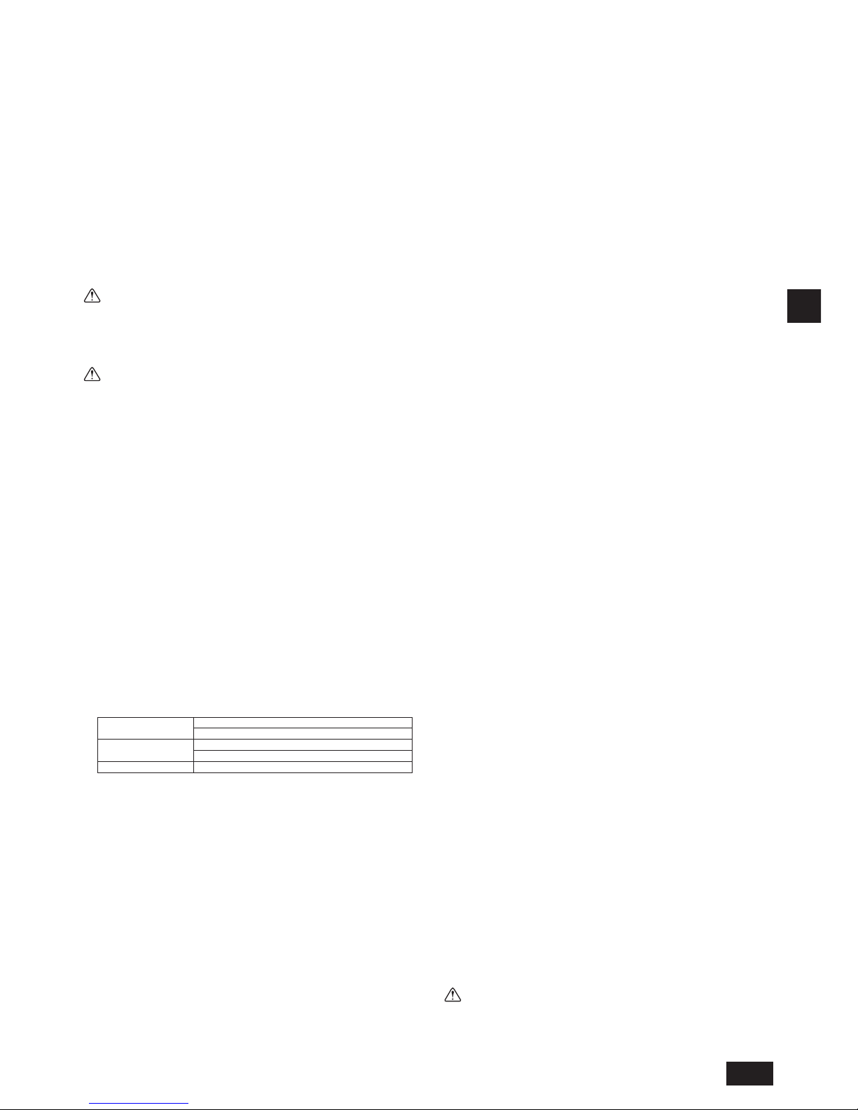
D
25
4.2. Arbeiten an der Kältemittelrohrleitung
Nach Anschluß der Kältemittelrohrleitungen aller Innenund Außenanlagen bei
vollständig geschlossenen Absperrventilen der Außenanlagen, die Außenanlagen
über die Absperrventile der Wartungseinheiten der Außenanlagen evakuieren.
Nach dem Ausführen der obigen Schritte die Absperrventile der Außenanlage
öffnen. Dadurch wird der Kältekreis (zwischen Außenanlage und BC-Steuerung)
vollständig angeschlossen.
Beschreibungen über die Behandlung der Ventilspindeln nden sich auf jeder
Außenanlage.
Hinweise:
• Nach Rohrleitungsanschluß mit einem Lecksensor oder einer Seifenlauge
vergewissern, daß kein Gas austritt.
• Vor dem Löten der Kältemittelrohre die Rohre am Gerätekörper und die
Wärmeisolierungsrohre immer mit feuchten Tüchern umwickeln, um
Wärmeschrumpfen und Verbrennen der Wärmeisolierungsrohre zu vermeiden. Dafür sorgen, daß die Flamme nicht mit dem Anlagenkörper in Berüh-
rung kommt.
• Keine Zusatzmittel für Leckentdeckung verwenden.
Warnung:
Bei der Aufstellung oder der Ortsveränderung nichts anderes als das
angegebene Kältemittel (R410A) in den Kältemittelkreislauf einspeisen. Die
Vermischung mit Luft kann bewirken, dass der Kältemittelkreislauf
abnormal hohe Temperaturen erreicht und dadurch die Leitungen platzen.
Achtung:
Schneiden Sie das Ende der Außengeräterohrleitung ab, entfernen Sie
zuerst das Gas und dann die hartgelötete Kappe.
[Fig. 4.2.1] (P.5)
Ⓐ Hier abschneiden
Ⓑ Gelötete Muffe entfernen
4.3. Isolieren der Kältemittelrohrleitungen
Die Kältemittelleitungen müssen unbedingt durch getrenntes Abdecken der
Hochdruckund Niederdruckrohrleitung mit ausreichend dickem, hitzebeständigem Polyethylen isoliert werden, so dass kein Spalt an der Nahtstelle des
Innengeräts und des Isoliermaterials sowie am Isoliermaterial selbst vorhanden
ist. Bei einer unzureichenden Isolierung kann Kondensat abtropfen usw. Achten
Sie insbesondere auf die sorgfältige Isolierung im Deckenbereich.
[Fig. 4.3.1] (P.5)
Ⓐ Dämmmaterial für Rohrleitungen (nicht im Lieferumfang enthalten)
Ⓑ Hier mit Band oder Klebeband befestigen.
Ⓒ Keine Öffnung frei lassen.
Ⓓ Überlappung des Randes: mehr als 40 mm
Ⓔ Dämmmaterial (nicht im Lieferumfang enthalten)
Ⓕ Dämmmaterial auf der Geräteseite
Ⓖ Mindestens 30 mm
• Isoliermaterial für die vor Ort zu installierenden Rohrleitungen muss die
folgenden technischen Daten aufweisen:
Außenanlage
- BC-Steuerung
Hochdruckleitung: 10 mm oder mehr
Niederdruckleitung: 20 mm oder mehr
BC-Steuerung
- Innengerät
Rohrgröße 6,35 bis 25,4 mm: 10 mm oder mehr
Rohrgröße 28,58 bis 41,28 mm: 15 mm oder mehr
Temperaturbeständigkeit
100 °C oder höher
• Beim Installieren von Rohrleitungen in einer sehr warmen und feuchten
Umgebung wie zum Beispiel in der obersten Etage eines Gebäudes ist unter
Umständen dickeres Dämmmaterial als das in der Tabelle, oben, spezizierte
erforderlich.
• Wenn bestimmte Anforderungen des Kunden erfüllt werden müssen, sollten
Sie Sorge tragen, dass diese auch die in der obigen Tabelle angegebenen
technischen Daten erfüllen.
• Die hartgelöteten Verbindungen müssen so mit Isoliermaterial abgedeckt
werden, dass die Schnittäche oben liegt und mit Bändern gesichert ist.
• Das aus der BC-Steuerung hervorstehende Rohr dämmen, wenn das Rohr
nicht an andere Rohre angeschlossen wird.
[Fig. 4.3.2] (P.5)
Ⓐ Dämmmaterial (nicht im Lieferumfang enthalten)
Ⓑ Hier mit Band oder Klebeband befestigen.
4.4. Arbeiten an der Auslaufrohrleitung
1. Arbeiten an der Auslaufrohrleitung
• Die Ablaufwanne kippen, so dass das Wasser in Richtung des Ablaufs ießt.
[Fig. 4.4.1] (P.5)
① Die beiden Schrauben lösen, die die seitliche Abdeckung auf der
rechten Seite des Steuerungskastens halten.
② Die Ablaufwanne kippen.
③ Schrauben bei geneigter Ablaufwanne befestigen.
• Dafür sorgen, daß die Auslaufrohrleitung zur Außenanlage (Abwasserseite)
eine Abwärtsneigung (Neigungsverhältnis von mehr als 1/100) aufweist. Auf
dem Weg dürfen keine Stolperfallen oder Unebenheiten sein.
• Dafür sorgen, dass abzweigende Auslaufrohrleitungen weniger als 20 m lang
sind (mit Ausnahme des Höhenunterschieds). Falls die Abussrohrleitung
sehr lang ist, mit Hilfe von Metallklammern stabilisieren. Keine Entlüftungslei-
tung anbringen! Sonst kann der Ablauf ausgelöst werden.
• Als Auslaufrohrleitung Rohre aus Vinylchlorid VP-25 (mit einem Außendurch-
messer von 32 mm) verwenden.
• Sicherstellen, dass die Abwasserausgänge 10 cm tiefer liegen als der
Ablaufanschluss des Gerätegehäuses.
• Am Abwasserausgang keinen Geruchsverschluss anbringen.
• Das Ende der Ablaufrohrleitung so positionieren, dass sich keine Gerüche
bilden können.
• Das Ende der Auslaufrohrleitung nicht in einen Abuss leiten, in dem sich
ionische Gase bilden.
[Fig. 4.4.2] (P.6)
○ Korrekte Verrohrung
× Unkorrekte Verrohrung
Ⓐ Dämmung (9 mm oder mehr)
Ⓑ Gefälle (1/100 oder mehr)
Ⓒ Metallstütze
Ⓚ Entlüfter
Ⓛ Angehoben
Ⓜ Geruchsverschluss
Gruppierte Rohrleitungen
Ⓓ Außendurchm. ø32 PVC-ROHR
Ⓔ So groß wie möglich. Etwa 10 cm.
Ⓕ Innengerät
Ⓖ Für gruppierte Rohrleitungen große Rohrgrößen verwenden.
Ⓗ Gefälle (1/100 oder mehr)
Ⓘ
Außendurchm. ø38 PVC-ROHR für gruppierte Rohrleitungen. (9 mm oder mehr Dämmung)
Ⓙ BC-Steuerung
1. Den Abussleitung (Zubehör) in den Ablaufanschluss einführen (Anschluss-
größe: 32 mm). (Der Abussleitung darf nicht mehr als 45° gebogen
werden, da sie sonst brechen oder verstopfen kann.)
(Den Schlauch mit Kleber befestigen und mit dem Band (klein, mitgeliefert) befestigen.)
2. Das Abussrohr befestigen (Außendurchm. ø32 PVC-ROHR PV-25, nicht
im Lieferumfang enthalten).
(Das Rohr mit Kleber befestigen und mit dem Band (klein, mitgeliefert) befestigen.)
3. Das Abussrohr (Außendurchm. ø32 PVC-ROHR PV-25) und den
Anschluss (einschließlich Rohrbogen) dämmen.
4. Drainage prüfen.
5. Das Dämmmaterial befestigen und mit dem Band (klein, mitgeliefert)
befestigen, um den Ablaufanschluss zu dämmen.
[Fig. 4.4.3] (P.6)
Ⓐ BC-Steuerung
Ⓑ Befestigungsband (im Lieferumfang enthalten)
Ⓒ Sichtbarer Teil
Ⓓ Anschlussgröße
Ⓔ Abussleitung (im Lieferumfang enthalten)
Ⓕ Abussrohr (Außendurchm. ø32 PVC-ROHR, nicht im Lieferumfang enthalten)
Ⓖ Dämmmaterial (nicht im Lieferumfang enthalten)
Ⓗ Befestigungsband (im Lieferumfang enthalten)
2. Abußtest
Öffnen Sie nach abgeschlossener Installation der Rohrleitungen die BC-SteuerungKonsole und testen Sie mit einer kleineren Wassermenge die Funktion des Ablaufs.
Überprüfen Sie außerdem, dass an den Anschlussstellen kein Wasser austritt.
3. Isolierung der Auslaufrohrleitungen
Isolieren Sie die Abussleitungen ebenso sorgfältig wie die Kühlmittelleitungen.
Achtung:
Versehen Sie die Abussleitungen mit einer Wärmedämmung, um übermäßige Kondensation zu verhindern. Ohne Ableitungssystem könnte Wasser aus
dem Gerät austreten und in Ihren Räumlichkeiten Schäden anrichten.
Page 26

D
26
5. Elektroarbeiten
► Zunächst alle gesetzlichen Bestimmungen beachten und die Energie-
versorgungsunternehmen zu Rate ziehen.
Warnung:
Arbeiten an der Elektrik sollten von qualizierten Fachleuten unter
Beachtung aller damit verbundenen Vorschriften und mit Hilfe der
vorhandenen Handbücher ausgeführt werden. Auch sind gesonderte
Stromkreise zu verwenden. Bei zu geringer Stromversorgung oder bei
unsachgemäß ausgeführten Elektroarbeiten besteht die Gefahr von
Stromschlägen oder Brandgefahr.
► Schließen Sie alle Kabel fest und sorgfältig an.
• Das Stromquellenkabel mit einer Pufferhülse gegen Zugkraft (PG-Anschluss
oder dergleichen) an der Steuerung anschließen.
[Fig. 5.0.1] (P.6)
Ⓐ Steuerung
Ⓑ Stromkabel
Ⓒ ø21 Loch (Buchse mit Gummiverschluss)
Ⓓ Übertragungsleitung
► Niemals Stromkabel an Klemmleisten für Steuerkabel anschließen. (Sie
können sonst brechen.)
► Dafür sorgen, daß die Klemmleisten der Steuerleitung mit Innenanlage,
Außenanlage und BC-Steuerung verdrahtet ist.
Verwenden Sie nicht-polarisierte 2-adrige Kabel als Übertragungskabel.
Abgeschirmte 2-Kernkabel (CVVS, CPEVS) von mehr als 1,25 mm
2
Durchmesser als Übertragungskabel verwenden.
Die Schaltkapazität des Netzstroms zu den BC-Steuerungen und die Leitungs-
größen sind wie folgt ausgelegt:
Schalter (A) Trennschalter
mit Kunststoff-
Formgehäuse
Erdschlußun-
terbrecher
Leitungsgröße
Kapazität Sicherung
16 16 20 A
20 A 30 mA
0,1 s oder
weniger
1,5 mm
2
• Nähere Informationen nden sich im Installationshandbuch der Außenanlage.
• Netzkabel für Elektrogeräte dürfen nicht leichter sein als eine Ausführung
gemäß 245 IEC 53 oder 227 IEC 53.
• Bei der Installation der Klimaanlage muß ein Schalter mit mindestens 3 mm
Kontaktabstand an jedem Pol vorgesehen werden.
Achtung:
Nur Sicherungen und Unterbrecher mit der richtigen Kapazität verwenden.
Sicherungen, Leiter oder Kupferdrähte mit zu großer Kapazität können
Fehlfunktionen verursachen oder Brände nach sich ziehen.
Darauf achten, daß die Außenanlagen geerdet sind. Die Erdleitungen nicht
an Gasrohre, Wasserrohre, Beleuchtungsstäbe oder Telefonerdkabel
anschließen. Durch unsachgemäße Erdung können Stromschläge
verursacht werden.
6. Einstellung der Adressen und Betrieb der Anlage
Der Adressenschalter jeder BC-Steuerung ist bei Versand ab Werk auf „000“
eingestellt.
• Den Adressschalter auf 1 + Adresse des Außengeräts (Wärmequelle) einstellen.
► Die BC-Steuerungsadresse muss normalerweise auf 1 + Adresse des
Außengeräts (Wärmequelle) eingestellt werden. Wenn sich dadurch
allerdings die gleiche Adresse wie die eines anderen Außengeräts
ergibt, die Adresse auf einen Wert zwischen 51 und 100 einstellen und
vergewissern, dass sie sich von der Adresse anderer BC-Steuerungen
unterscheidet.
• Dazu bitte im Installationshandbuch des Außengeräts (Wärmequelle) nachsehen.
7. Testlauf
Beachten Sie vor der Durchführung eines Testlaufs
Folgendes:
► Nachdem Sie die Innenanlagen aufgestellt, alle Kabel und Rohrleitun-
gen verlegt und die BC-Steuerungen angeschlossen haben, vergewissern Sie sich erneut, dass nirgendwo Kühlmittel austritt und die
Stromund Steuerkabel fest angeschlossen sind.
► Verwenden Sie einen 500-V-Widerstandsmesser, um zu überprüfen,
dass zwischen dem Anschlussblock der Stromversorgung und dem
Boden ein Isolationswiderstand von über 1,0 MΩ besteht. Falls der
Widerstand unter 1,0 MΩ liegt, darf die Anlage nicht betrieben werden.
Achtung:
Messen Sie niemals den Isolationswiderstand des Anschlussblocks für die
Steuerkabel.
Page 27
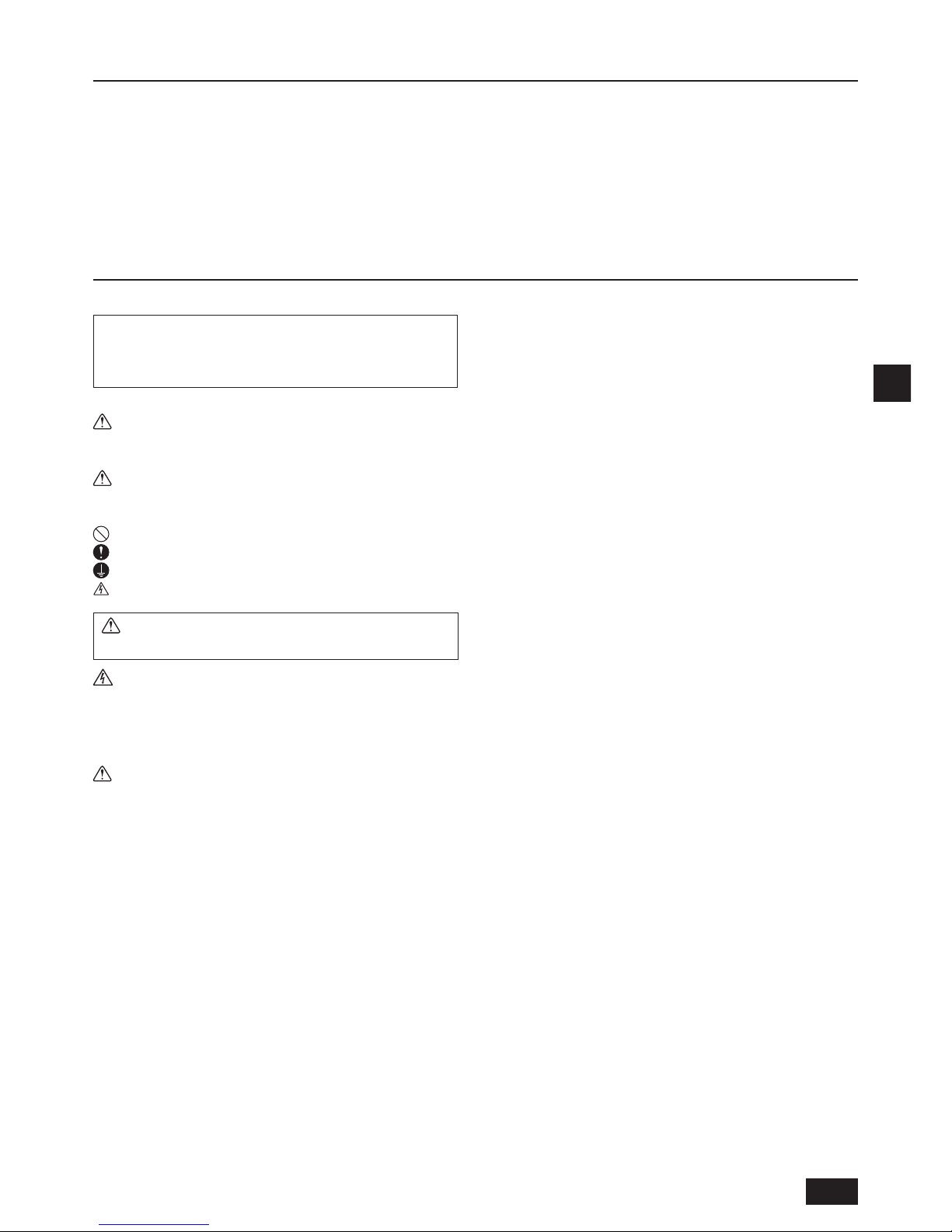
F
27
1. Précautions de sécurité
1.1. Avant installation et travaux électriques
► Avant d’installer l’unité, ne manquez pas de lire toutes les
“Précautions de sécurité”.
► Les “Précautions de sécurité” fournissent des points très
importants concernant la sécurité. Ne manquez pas de les observer.
Symboles utilisés dans le texte
Avertissement :
Décrit les précautions qui doivent être prises pour éviter les risques de
blessure ou de mort de l’utilisateur.
Attention :
Décrit les précautions qui doivent être prises pour éviter d’endommager l’appareil.
Symboles utilisés dans les illustrations
: Indique une action qui doit être évitée.
: Indique que des instructions importantes doivent être observées.
: Indique une pièce qui doit être mise à la terre.
: Risque d’électrocution (Ce symbole est afché sur l’étiquette de l’unité
principale.) <Couleur : Jaune>
Avertissement :
Lisez soigneusement les étiquettes apposées sur l’unité principale.
AVERTISSEMENT DE HAUTE TENSION:
• Le boîtier de commande abrite des pièces à haute tension.
• En ouvrant ou en fermant le panneau avant du boîtier de commande, ne
le laissez pas venir en contact avec des composants internes.
• Avant d’inspecter l’intérieur de la boîte de commande, coupez le courant,
laissez l’unité hors circuit pendant au moins 10 minute.
Avertissement :
• Si le câble électrique est endommagé, il doit être remplacé par le fabricant,
un de ses techniciens ou des personnes aux qualications similaires pour
éviter tout risque éventuel.
• Cet appareil n’a pas été conçu pour être utilisé par des personnes
(y compris des enfants) avec des capacités physiques, sensorielles ou
mentales réduites, ou avec un manque d’expérience et de connaissances,
à moins qu’elles ne soient surveillées et formées à son utilisation par une
personnes responsable de leur sécurité.
• Cet appareil n’a été conçu que pour être utilisé par des utilisateurs experts
ou formés en atelier, dans des industries légères et des exploitations agricoles,
ou pour une utilisation commerciales par des personnes formées à cet effet.
• N’utilisez pas de réfrigérant d’un autre type que celui indiqué dans les
manuels fournis avec l’appareil et la plaque signalétique.
- Cela pourrait provoquer une brûlure de l’appareil ou de ses conduites, une
explosion ou un incendie pendant l’utilisation, la réparation ou lors de
l’élimination de l’appareil.
- Cette action pourrait également enfreindre les lois applicables.
- MITSUBISHI ELECTRIC CORPORATION ne peut être tenu pour
responsable en cas de dysfonctionnements ou d’accidents provoqués par
l’utilisation d’un type de réfrigérant incorrect.
• Demandez au distributeur ou à un technicien autorisé d’installer le climatiseur.
- Une installation incorrecte par l’utilisateur peut avoir comme conséquence
une fuite d’eau, une électrocution ou un incendie.
• Installez l’unité à un endroit qui peut soutenir son poids.
- Si ce n’est pas pris en compte, l’unité peut tomber et blesser quelqu’un ou
être endommagée.
• Utiliser les câbles spéciés pour le câblage. Faites des branchements solides
de sorte que la force extérieure du câble ne soit pas appliqué aux bornes.
- Un branchement et une xation inadéquats peuvent s’échauffer et causer
un incendie.
• Soyez préparés en cas de vents forts et de tremblements de terre et installez l’unité à la place indiquée.
- Une installation incorrecte peut faire renverser l’unité et provoquer des
blessures ou endommager l’unité.
• Utilisez toujours les accessoires spéciés par Mitsubishi Electric.
- Demandez à un technicien autorisé d’installer les accessoires. Une
installation incorrecte par l’utilisateur peut avoir comme conséquence une
fuite d’eau, une électrocution ou un incendie.
• Ne réparez jamais l’unité. Si le climatiseur doit être réparé, consultez le distributeur.
- Une réparation incorrecte par l’utilisateur peut avoir comme conséquence
une fuite d’eau, un choc électrique ou un incendie.
• Ne touchez pas les tuyaux de réfrigérant.
- Toute manipulation incorrecte pourrait provoquer des blessures.
• Lors de la manipulation de ce produit, veillez à toujours porter des
équipements de protection.
C’est-à-dire : Gants, combinaison intégrale et lunettes de sécurité.
- Toute manipulation incorrecte pourrait provoquer des blessures.
• En cas de fuite du gaz frigorigène pendant l’installation, aérez la pièce.
- Si le gaz frigorigène vient en contact avec une amme, des gaz toxiques se dégagent.
• Installez le climatiseur conformément à ce Manuel d’installation.
- Une installation incorrecte peut avoir comme conséquence une fuite d’eau,
un choc électrique ou un incendie.
• Faites effectuer tous les travaux électriques par un électricien licencié selon
les “Normes techniques des installations électriques”, les “Règlements
relatifs aux câblages intérieurs” et les instructions données dans ce manuel,
et utilisez toujours une alimentation dédiée.
- Si la source d’énergie est inadéquate ou les travaux électriques sont exécutes
incorrectement, un risque de choc électrique et d’incendie peut en résulter.
• Tenez les pièces électriques à distance de l’eau (eau de lavage, etc.).
- Le contact pourrait provoquer une électrocution, un départ d’incendie ou de la fumée.
• Fixez correctement le couvercle du boîtier de commande.
- Si vous ne xez pas correctement le couvercle, de la poussière ou de l’eau risque de
pénétrer dans l’appareil extérieur et de provoquer un incendie ou une électrocution.
• En installant et en déplaçant le climatiseur vers un autre site, ne le chargez
pas avec un frigorigène différent de celui qui est spécié sur l’unité.
- Si un autre frigorigène ou de l’air est mélangé au frigorigène original, le
cycle frigorique peut mal fonctionner et l’unité peut être endommagée.
• Si le climatiseur est installé dans une petite pièce, des mesures doivent
être prises pour empêcher la concentration en frigorigène de dépasser la
limite de sécurité en cas de fuite du frigorigène.
- Consultez le distributeur au sujet des mesures appropriées pour empêcher
la limite de sécurité d’être excédée. En cas de fuite du frigorigène et de
dépassement de la limite de sécurité, les risques dus au manqué d’oxygène
dans la pièce peuvent exister.
• Pour déménager et réinstaller le climatiseur, consultez le distributeur ou
un technicien autorisé.
- Une installation incorrecte du climatiseur peut avoir comme conséquence
une fuite d’eau, un choc électrique ou un incendie.
• Après avoir terminé les travaux d’installation, vériez que le gaz frigorigène
ne fuit pas.
- Si le gaz frigorigène fuit et est exposé à un radiateur-ventilateur, cuisinière,
four ou toute autre source de chaleur, des gaz nocifs peuvent se produire.
• Ne reconstruisez pas ou ne changez pas les congurations des dispositifs
de protection.
- Si le pressostat, le rupteur thermique, ou autre dispositif de protection est
court-circuité ou forcé, ou si des pièces autres que celles spéciées par
Mitsubishi Electric sont utilisées, un incendie ou une explosion peut en résulter.
• Pour éliminer ce produit, consultez votre distributeur.
• L’installateur et le spécialiste système assureront la sécurité contre les
fuites conformément aux normes et règlements locaux.
- Choisissez la dimension de câble appropriée et les capacités de commutation de l’alimentation principale décrites dans ce manuel si la réglementation locale n’est pas disponible.
• Faites particulièrement attention au lieu de l’installation, telle qu’un sous-sol, etc.
où le gaz frigorigène peut s’accumuler étant donné qu’il est plus lourd que l’air.
• Les enfants doivent être surveillés pour garantir qu’ils ne peuvent pas
jouer avec l’appareil.
Index
1. Précautions de sécurité .............................................................................. 27
1.1. Avant installation et travaux électriques.................................... 27
1.2.
Précautions pour les appareils qui utilisent le frigorigène R410A
.... 28
1.3. Avant l’installation ..................................................................... 28
1.4. Avant l’installation (déménagement) - travaux électriques ....... 28
1.5. Avant de commencer l’essai ..................................................... 28
2. Sélection d’un lieu d’installation ................................................................. 29
2.1. À propos du produit .................................................................. 29
2.2. Lieu d’installation ...................................................................... 29
2.3. Espace requis pour l’installation et pour l’entretien .................. 29
2.4. Vérication du lieu d’installation ................................................ 30
3. Installation du contrôleur BC ...................................................................... 33
3.1. Vérication des accessoires fournis avec le contrôleur BC ...... 33
3.2. Installation des contrôleurs BC ................................................. 33
4. Raccordement des tuyaux de réfrigérant et d’écoulement ......................... 33
4.1. Raccordement des tuyaux de réfrigérant .................................. 33
4.2. Travaux des tuyaux de réfrigérant ............................................ 35
4.3. Isolation des tuyaux de réfrigérant ............................................ 35
4.4. Mise en place du tuyau d’écoulement ...................................... 35
5. Travaux d’électricité....................................................................................36
6. Réglage des adresses et fonctionnement des appareils............................ 36
7. Essai de fonctionnement ............................................................................ 36
Page 28

F
28
1.2. Précautions pour les appareils qui
utilisent le frigorigène R410A
Avertissement :
• N’utilisez pas de réfrigérant d’un autre type que celui indiqué dans les
manuels fournis avec l’appareil et la plaque signalétique.
- Cela pourrait provoquer une brûlure de l’appareil ou de ses conduites, une explosion
ou un incendie pendant l’utilisation, la réparation ou lors de l’élimination de l’appareil.
- Cette action pourrait également enfreindre les lois applicables.
- MITSUBISHI ELECTRIC CORPORATION ne peut être tenu pour
responsable en cas de dysfonctionnements ou d’accidents provoqués par
l’utilisation d’un type de réfrigérant incorrect.
Attention :
• N’utilisez pas la tuyauterie de frigorigène existante.
- L’ancien frigorigène et l’huile réfrigérante présents dans la tuyauterie
existante contiennent une grande quantité de chlore qui peut détériorer
l’huile réfrigérante de la nouvelle unité.
- R410A est un frigorigène à haute pression qui peut faire éclater la tuyauterie existante.
• Utilisez une tuyauterie de frigorigène en cuivre désoxydé au phosphore et
des tuyaux et tubulures en alliage de cuivre sans soudure. En outre, assurez-
vous que les surfaces intérieures et extérieures des tuyaux sont propres et
dépourvues de soufre, d’oxydes, de poussières/saletés, de particules de rasage, d’huile, d’humidité, ou de n’importe quel autre contaminant dangereux.
- Les contaminants à l’intérieur de la tuyauterie du frigorigène peuvent
détériorer l’huile résiduelle du frigorigène.
• Entreposez à l’intérieur la tuyauterie à utiliser pour l’installation et gardez
scellées les deux extrémités de la tuyauterie jusqu’au moment du brasage.
(Stockez les coudes et autres raccords dans un sac en plastique.)
- Si de la poussière, des saletés, ou de l’eau pénètre dans le cycle
frigorique, il peut s’ensuivre une détérioration de l’huile et du compresseur.
• Appliquez une petite quantité d’huile d’ester, huile d’éther ou alkylbenzène
aux évasements. (pour l’appareil d’intérieur)
- L’inltration d’une grande quantité d’huile minérale peut détériorer l’huile réfrigérante.
• Utilisez un frigorigène liquide pour remplir le système.
- Si un gaz frigorigène est utilisé pour remplir le système, la composition du
frigorigène dans le cylindre change et la performance peut chuter.
• N’utilisez pas de frigorigène autre que le R410A.
- Si un autre frigorigène (R22, etc.) est mélangé au R410A, le chlore dans le
frigorigène peut détériorer l’huile réfrigérante.
• Utilisez une pompe à vide avec clapet anti-retour de ux inverse.
- L’huile de la pompe à vide peut reuer dans le cycle frigorique et détériorer
l’huile réfrigérante.
• N’utilisez pas les outils suivants qui sont utilisés avec les frigorigènes conventionnels.
(Manomètre de pression, tuyau exible de charge, détecteur de fuite de gaz, clapet
anti-retour de ux inverse, base de charge du frigorigène, équipement de
récupération du frigorigène)
- Si un frigorigène conventionnel et de l’huile réfrigérante sont mélanges
avec le R410A, le frigorigène peut être détérioré.
- Si de l’eau est mélangée au R410A, l’huile réfrigérante peut être détériorée.
- Puisque le R410A ne contient aucun chlore, les détecteurs de fuite de gaz pour
les frigorigènes conventionnels ne réagissent pas.
• N’utilisez pas de cylindre de chargement.
- Utiliser un cylindre de chargement peut détériorer le frigorigène.
• N’utilisez pas d’antioxydant ni d’additif de détection des fuites.
• Faites particulièrement attention en manipulant les outils.
- Si de la poussière, des saletés ou de l’eau pénètre dans le cycle frigorique,
le frigorigène peut se détériorer.
1.3. Avant l’installation
Attention :
• N’installez pas l’unité là où un gaz combustible peut fuir.
- Si le gaz fuit et s’accumule autour de l’unité, une explosion peut se produire.
• N’utilisez pas le climatiseur là où se trouve de la nourriture, des animaux
domestiques, des plantes, des instruments de précision ou des objets d’art.
- La qualité de la nourriture, etc. peut se détériorer.
• N’utilisez pas le climatiseur dans des environnements spéciaux.
- L’huile, la vapeur, la fumée sulfurique, etc. peuvent réduire de manière
signicative la performance du climatiseur ou endommager ses pièces.
• En installant l’unité dans un hôpital, un centre de transmission ou site
semblable, assurez une protection sufsante contre le bruit.
- Les convertisseurs, les générateurs privés d’alimentation électrique, les équipements
médicaux à haute fréquence ou les équipements de radiocommunication peuvent
provoquer le dysfonctionnement du climatiseur, ou l’empêcher de fonctionner. D’un
autre côté, le climatiseur peut affecter le fonctionnement de ces équipements en
raison du bruit qui gêne le traitement médical ou la transmission d’images.
• N’installez pas l’unité sur une structure qui peut provoquer une fuite.
- Lorsque l’humidité de la pièce dépasse 80 % ou que le tuyau d’écoulement est bouché,
il se peut que des gouttes d’eau tombent de l’appareil intérieur ou du contrôleur BC.
Exécutez un travail de drainage collectif avec l’unité extérieure, selon besoins.
• Vériez que vous avez bien extrait le styrène en mousse entre l’appareil
et le bac de vidange.
1.4. Avant l’installation (déménagement) travaux électriques
Attention :
• Mettez l’unité à la terre.
- Ne connectez pas le l de terre aux conduites de gaz ou d’eau, aux
paratonnerres, ou aux lignes de terre du téléphone. Une mise à la terre
incorrecte peut avoir comme conséquence un choc électrique.
• Installez le câble d’alimentation de sorte que la tension ne soit pas appliquée au câble.
- La tension peut fracturer le câble, produire un échauffement et causer un
incendie.
• Installez un disjoncteur de fuite, selon besoins.
- Si un disjoncteur de fuite n’est pas installé, un choc électrique peut en résulter.
• Utilisez des câbles d’alimentation ayant une capacité de charge et une
valeur nominale sufsantes.
- Les câbles qui sont trop petits peuvent fuir, s’échauffer, et provoquer un
incendie.
• Utilisez seulement un disjoncteur et un fusible de la capacité spéciée.
- Un fusible ou un disjoncteur d’une plus grande capacité, ou utiliser à la
place un simple l d’acier ou de cuivre peuvent avoir comme conséquence
une défaillance générale de l’unité ou un incendie.
• Ne lavez pas le climatiseur.
- Le lavage peut causer une décharge électrique.
• Assurez-vous que la base d’installation n’a pas été endommagée par suite
d’un usage prolongé.
- Si les dommages ne sont pas réparés, l’unité peut tomber et causer des
blessures ou des dégâts matériels.
• Installez la tuyauterie de drainage conformément à ce Manuel d’installation
pour assurer un drainage approprié. Enveloppez les tubes d’isolation
thermique pour empêcher la condensation.
- Une tuyauterie de drainage inappropriée peut causer une fuite d’eau et
endommager le mobilier et autres objets.
• Faites très attention lors du transport du produit.
- Le produit ne doit pas être porté par une seule personne. Son poids excède
20 kg.
- Certains produits utilisent des bandes PP pour l’emballage. N’utilisez pas
de bande PP en tant que moyen de transport. C’est dangereux.
• Éliminez sécuritairement les matériaux d’emballage.
- Les matériaux d’emballage, tels que des clous et autres pièces en métal ou
en bois, peuvent causer des blessures.
- Déchirez et jetez les sacs d’emballage en plastique de sorte que les
enfants ne jouent pas avec. Si des enfants jouent avec un sac en plastique
qui n’a pas été déchiré, ils risquent de suffoquer.
1.5. Avant de commencer l’essai
Attention :
• Mettez sous tension pendant au moins 12 heures avant de mettre en route.
- La mise en route immédiatement après la mise sous tension peut causer
des dommages irréversibles aux pièces internes. Laissez l’interrupteur de
courant en position sous tension pendant la saison d’exploitation.
• Ne touchez pas les interrupteurs avec des doigts mouillés.
- Toucher un interrupteur avec des doigts mouillés peut causer une décharge
électrique.
• Ne touchez pas les tuyaux de réfrigérant pendant et immédiatement après
le fonctionnement.
- Pendant et juste après le fonctionnement, les tuyaux de réfrigérant peuvent
être chauds ou froids, selon l’état du frigorigène s’écoulant dans la
tuyauterie, le compresseur et autres pièces du cycle frigorique. Vos mains
peuvent subir des brûlures ou gelures si vous touchez les tuyaux de
réfrigérant.
• Ne faites pas fonctionner le climatiseur avec les panneaux et protections
retirés.
- Les pièces rotatives, chaudes, ou sous haute tension peuvent causer des
blessures.
• Ne coupez pas le courant immédiatement après avoir arrêté le fonctionnement.
- Attendez toujours au moins 5 minutes avant de couper le courant.
Autrement, une fuite de l’eau de drainage ou une défaillance mécanique
des pièces sensibles pourrait se produire.
Page 29
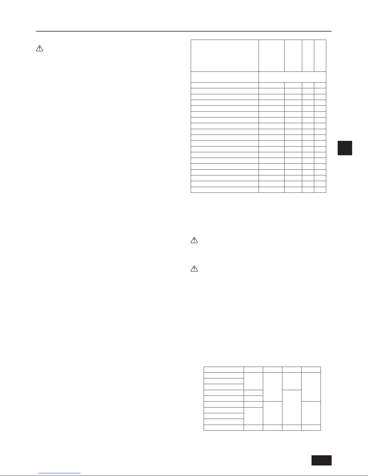
F
29
2. Sélection d’un lieu d’installation
2.1. À propos du produit
Avertissement :
• N’utilisez pas de réfrigérant d’un autre type que celui indiqué dans les
manuels fournis avec l’appareil et la plaque signalétique.
- Cela pourrait provoquer une brûlure de l’appareil ou de ses conduites, une
explosion ou un incendie pendant l’utilisation, la réparation ou lors de
l’élimination de l’appareil.
- Cette action pourrait également enfreindre les lois applicables.
- MITSUBISHI ELECTRIC CORPORATION ne peut être tenu pour
responsable en cas de dysfonctionnements ou d’accidents provoqués par
l’utilisation d’un type de réfrigérant incorrect.
• Cet appareil utilise un frigorigène de type R410A.
• La tuyauterie des systèmes utilisant le R410A peut être différente de celle
des systèmes utilisant un frigorigène conventionnel car la pression de
conception est plus élevée. Reportez-vous au Livre de données pour plus
d’informations.
• Certains outils et équipements utilisés pour l’installation de systèmes
fonctionnant avec d’autres types de frigorigènes ne peuvent pas être utilisés
pour les systèmes fonctionnant avec le R410A. Reportez-vous au Livre de
données pour plus d’informations.
• N’utilisez pas la tuyauterie existante, car elle contient du chlore, qui est
présent dans l’huile et le frigorigène de machines conventionnelles de
frigorication. Ce chlore détériore l’huile réfrigérante de machine dans le
nouvel équipement. La tuyauterie existante ne doit pas être utilisée car la
pression de conception dans les systèmes utilisant le R410A est plus élevée
que dans les systèmes utilisant d’autres types de frigorigènes et les tuyaux
existants peuvent éclater.
2.2. Lieu d’installation
• Installez l’appareil dans un endroit à l’abri de la pluie. Le contrôleur BC doit
être installé à l’intérieur.
• Prévoyez assez d’espace autour de l’appareil pour l’entretien.
• N’installez pas l’appareil dans un endroit qui ne permet pas de respecter les
restrictions de longueur de la tuyauterie.
• N’installez pas l’appareil dans un endroit exposé directement à d’autres
sources de chaleur rayonnante.
• Ne jamais installer l’appareil dans un endroit soumis à des projections d’huile
(ou de graisse) ou à des vapeurs excessives ni à proximité d’un appareil
générant des hautes fréquences. Sinon, vous risquez des court-circuits, un
mauvais fonctionnement de l’appareil ou la présence de gouttes de
condensation.
• Prévoyez un espace sufsant pour permettre le branchement aisé des tuyaux
d’eau et de frigorigène ainsi que des câbles électriques.
• Eviter tout endroit exposé à la génération, à l’arrivée, à l’accumulation ou à
des fuites de gaz inammables ou sulfuriques.
• Laissez une pente d’au moins 1/100 pour le tuyau d’écoulement.
• Installez correctement l’appareil sur une surface stable et porteuse.
• N’installez pas l’appareil dans un lieu soumis à une grande quantité de
vapeur. L’utilisation de l’appareil dans un environnement humide peut
provoquer de la condensation pendant la réfrigération.
• Si l’intérieur du plafond sur lequel l’appareil est installé devient chaud et
humide, l’utilisation de l’appareil pendant une période prolongée dans un tel
environnement peut provoquer de la condensation. Cela ne pose néanmoins
aucun problème puisque l’eau de condensation s’écoulera dans un bac de
vidange. Même si la partie soumise à la condensation peut blanchir, cela n’a
pas d’impact sur le fonctionnement normal de l’appareil.
• Vériez que l’eau de condensation de l’appareil ne touche pas les câblages
de l’entourage.
1. Pour la suspension au plafond [Fig. 2.2.1] (P.2)
• Effectuez un trou d’inspection de 450 mm2 dans la surface du plafond comme
illustré à la [Fig. 2.3.1] (P.2).
• Installez l’appareil dans un endroit adapté (plafond d’un couloir, salle de bain,
etc.) peu fréquenté. Évitez de l’installer au milieu d’une pièce.
• Prévoyez une résistance à la traction d’au moins 60 kg par boulon pour les
boulons de suspension.
• Veillez à installer le contrôleur BC horizontalement.
• Installez l’appareil dans un endroit où le bruit du contrôleur BC ne sera pas
problématique.
• Installez l’appareil dans un endroit où le bruit de fonctionnement ne sera pas
problématique. (Dans les endroits à faible bruit de fond, (chambres d’hôtel,
par exemple), installez l’appareil intérieur et le contrôleur BC à au moins 5 m
l’un de l’autre).
Le niveau de pression sonore est le suivant.
Le niveau de pression sonore [dB] <Échelle A>
Nom du modèle du contrôleur BC
CMB-P104V-J
CMB-P106V-J
CMB-P108V-J
CMB-P1012V-J
CMB-P1016V-J
CMB-P108V-JA
CMB-P1012V-JA
CMB-P1016V-JA
CMB-P1016V-KA
CMB-P104V-KB
Connecté à l’extérieur (source de
chaleur) capacité d’unité
Valeur maximale pendant le
fonctionnement normal ou le dégivrage
(E)P200 49 53 55 49
(E)P250 49 53 55 49
(E)P300 49 53 55 49
(E)P350 53 55 55 53
(E)P400 - 56 55 (E)P450 - 56 55 (E)P500 - 56 55 (E)P550 - 56 55 (E)P600 - 56 55 (E)P650 - 56 55 (E)P700 - 56 55 (E)P750 - 56 55 (E)P800 - 56 55 (E)P850 - 56 55 (E)P900 - 56 55 (E)P950 - - 55 (E)P1000 - - 55 (E)P1050 - - 55 (E)P1100 - - 55 -
*1. Les valeurs du niveau de pression sonore ont été obtenues dans une
chambre anéchoïque. Le niveau de pression sonore réel est généralement supérieur à celui mesuré dans la chambre anéchoïque en raison du
bruit ambiant et du son rééchi.
*2. Les valeurs de niveau de pression sonore ont été obtenues à l’emplace-
ment au-dessous de 1,5 m de l’appareil.
*3. Le son de commutation de la vanne solénoïde est de 56 dB, indépen-
damment du modèle de l’appareil.
Avertissement :
Veillez à installer l’appareil dans un endroit capable de soutenir son poids.
Si l’endroit n’est pas sufsamment résistant, l’appareil risque de tomber et
de blesser quelqu’un.
Attention :
Veillez à installer l’unité horizontalement.
2.3. Espace requis pour l’installation et pour
l’entretien
1. Pour la suspension au plafond
(Vue de référence montrant l’espace minimum requis pour l’installation.)
[Fig. 2.3.1] (P.2)
<A> Vue du haut
<B> Vue de devant
Ⓐ Trou d’inspection
Ⓑ Du côté des tuyaux de l’appareil extérieur
Ⓒ Boîte de commandes
Ⓓ Du côté des tuyaux de l’appareil intérieur
*1 Dimensions permettant le raccord des tuyaux sur le site.
Nom du modèle A B C D
CMB-P104V-J
596
-
429
250
CMB-P106V-J
CMB-P108V-J
CMB-P1012V-J 911
573
CMB-P1016V-J 1135
CMB-P108V-JA 911
250 300
CMB-P1012V-JA
1135CMB-P1016V-JA
CMB-P1016V-KA
CMB-P104V-KB 596 - 429 250
Page 30
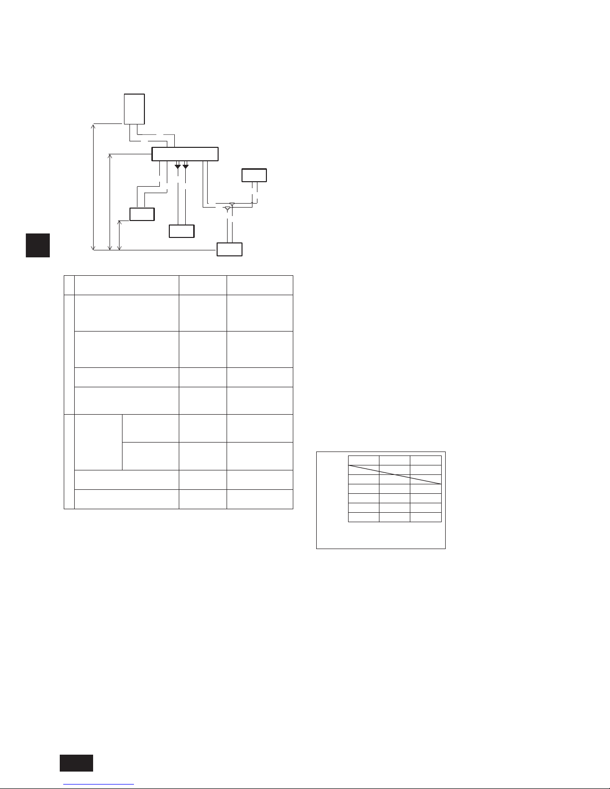
F
30
2.4. Vérication du lieu d’installation
Vérier que la différence d’élévation entre les appareils intérieurs et extérieurs et la longueur des tuyaux de réfrigérant soient conformes aux spécications requises.
1. CMB-P104, 106, 108, 1012, 1016V-J (si l’appareil extérieur est de 14-hp (modèle P350) ou moins, 16 ports maximum sont utilisés.)
CMB-P108, 1012, 1016V-JA, CMB-P1016V-KA (lorsqu’aucun contrôleur BC auxiliaire n’est connecté)
Ⓑ
Ⓓ
A
A
a
a
b
b
Ⓐ
Ⓔ
Ⓓ
Ⓓ
B
B
c
c
d
d
Ⓕ
Ⓖ
H
H1
h1
h2
(Appareil : m)
Article
Portion de
tuyauterie
Valeur permise
Longueur
Longueur de tuyauterie totale
“A+B+a+b
+c+d”
Ne dépassez pas la
longueur de tuyau
de frigorigène
maximum *1
Longueur de tuyauterie maximum “A+B+c”
165 ou moins
(longueur équivalente de 190 ou
moins)
Entre l’appareil extérieur (source
de chaleur) et le contrôleur BC
“A” 110 ou moins
Entre les appareils intérieurs et le
contrôleur BC
“a” ou “b” ou
“B+c” ou
“B+d”
60 ou moins *2
Différence de hauteur
Entre les
appareils
intérieur et
extérieur
(source de
chaleur)
Au-dessus de
l’appareil intérieur
(source de chaleur)
“H” 50 ou moins
En-dessous de
l’appareil extérieur
(source de chaleur)
“H1” 40 ou moins
Entre les appareils intérieurs et le
contrôleur BC
“h1”
15 or moins
(10 ou moins *3)
Entre les appareils intérieurs “h2”
30 or moins
(20 ou moins *3)
Ⓐ Appareil extérieur (Appareil source de chaleur)
Ⓑ Contrôleur BC (Principal)
Ⓒ Contrôleur BC (Aux)
Ⓓ Appareil intérieur (Capacité totale en aval de l’appareil intérieur : entre 15 et 80)
Ⓔ
Appareil intérieur (Capacité totale en aval de l’appareil intérieur : entre 100 et 250)
Ⓕ Tuyau jumelé (Nom du modèle : CMY-R160-J1)
Ⓖ Tuyau joint à 2 dérivations
Remarques:
*1 Reportez-vous à la section “Restrictions on piping length (Restrictions
de longueur de la tuyauterie)” à la P.3.
*2
Reportez-vous au graphique “Distance between main BC controller and
farthest indoor unit (direct connection) (Distance entre le contrôleur BC
principal et l’appareil intérieur le plus éloigné (connexion directe)”.
(Néanmoins lorsque le modèle d’appareil intérieur P200 ou P250 est
connecté, la distance maximale admissible entre le contrôleur BC et
l’appareil intérieur le plus éloigné est de 40 m.)
*3
Les valeurs entre parenthèses indiquent la longueur de tuyauterie
maximum à respecter lorsque la capacité de connexion de l’appareil
intérieur est d’au moins 200.
*4 Dans le système auquel les appareils intérieurs du modèle P200 ou
supérieur sont branchés, vous ne pouvez pas utiliser de joint ni de tête
de dérivation.
*5 Ne branchez pas les appareils intérieurs des modèles P200 ou P250 et
d’autres modèles sur le même port.
*6 Dans le système auquel les appareils intérieurs des modèles P100 à
P140 sont branchés, soudez les deux ports avant de les raccorder.
(Réglez le commutateur DIP SW4-6 du contrôleur du BC sur ON.)
*7 Il est possible de brancher les modèles P100 à P140 des appareils
intérieurs à un seul port. (Réglez DIP SW4-6 sur OFF.) Remarquez que la
capacité de réfrigération peut légèrement diminuer. (Le réglage d’usine
pour DIP SW4-6 est OFF.)
Si vous ne connectez que les appareils PEFY-P50/63/71/80VMHS2-E,
réglez les commutateurs SW4-1 et SW4-6 sur le contrôleur BC sur ON.
*8 Les appareils intérieurs branchés au même joint de dérivation ne
peuvent pas fonctionner simultanément dans des modes différents.
*9 Lorsque vous connectez les appareils PEFY-P50/63/71/80VMHS2-E sur
deux ports, utilisez un kit de tuyau de joint CMY-R160-J1.
Distance entre le contrôleur BC principal
et l’appareil intérieur le plus éloigné (connexion directe)
Distance entre le contrôleur BC
et l’appareil intérieur le plus éloigné (m)
15105
20
10
0
0
70
60
50
40
30
Différence de hauteur entre le contrôleur BC
et l’appareil intérieur le plus éloigné (m)
*10 Pour la connexion des appareils intérieurs modèles 15 à 50
Découpez le tuyau de connexion de l’appareil intérieur au niveau du point
de découpe qui dépend de la capacité de l’appareil intérieur pour effectuer
l’élargissement du tuyau.
Unité 1
Page 31

F
31
2. CMB-P108, 1012, 1016V-JA, CMB-P1016V-KA (lorsqu’aucun contrôleur BC auxiliaire n’est connecté)
Ⓓ
a
a
b
b
Ⓐ
Ⓔ
Ⓓ
Ⓓ
B
B
c
c
d
d
Ⓕ
Ⓖ
Ⓐ
Ⓒ
Ⓒ
Ⓒ
Ⓓ
Ⓓ
K
K
L
L
A
C
C
C
D
D
D
E
E
Ⓓ
Ⓒ
G
G
G
J
J
J
M
M
M
F
F
F
e
e
f
f
g
g
j
j
*1
Ⓖ
Ⓓ
h4
H
H1
h1
h1
h1 h3
h2
Ⓑ
E
Ⓖ
Ⓖ
A
(Appareil : m)
Article
Portion de
tuyauterie
Valeur permise
Longueur
Longueur de tuyauterie totale
“K+L+A+B+C
+D+E+F+G+J
+M+a+b+c+d
+e+f+g+j”
Ne dépassez pas la
longueur de tuyau de
frigorigène maximum *1
Longueur de tuyauterie maximum
“K(L)+A+C
+E+G+J+j”
165 ou moins
(longueur équivalente de 190 ou
moins)
Entre l’appareil extérieur (source
de chaleur) et le contrôleur BC
principal
“K(L)+A” 110 ou moins
Contrôleur BC à connexion
directe entre les appareils
intérieurs (Principal ou Aux.)
“a” ou “b” ou
“B+c” ou
“B+d” ou “e”
ou “f” ou “g”
ou “j”
60 ou moins *2
Entre les appareils intérieurs et le
contrôleur BC principal par le
contrôleur BC auxiliaire
“C+D+e” ou
“C+E+F+f” ou
“
C+E+G+M+g
”
ou
“C+E+G+J+j”
90 ou moins *3
Différence de hauteur
Entre les
appareils
intérieur et
extérieur
(source de
chaleur)
Au-dessus de
l’appareil intérieur
(source de chaleur)
H 50 ou moins
En-dessous de
l’appareil extérieur
(source de chaleur)
H1 40 ou moins
Entre le contrôleur BC (Principal
et Auxiliaire) et l’appareil intérieur
h1
15 or moins
(10 ou moins *4)
Entre les appareils intérieurs h2
30 or moins
(20 ou moins *4)
Entre le contrôleur BC (Principal
et Auxiliaire) et le contrôle de BC
Auxiliaire
h3 15 ou moins
Entre les appareils extérieurs
(source de chaleur)
h4 0,1 ou moins
Ⓐ Appareil extérieur (Appareil source de chaleur)
Ⓑ Contrôleur BC (Principal)
Ⓒ Contrôleur BC (Aux)
Ⓓ Appareil intérieur (Capacité totale en aval de l’appareil intérieur : entre 15 et 80)
Ⓔ
Appareil intérieur (Capacité totale en aval de l’appareil intérieur : entre 100 et 250)
Ⓕ Tuyau jumelé (Nom du modèle : CMY-R160-J1)
Ⓖ Tuyau joint à 2 dérivations
Remarques:
*1 Reportez-vous à la section “Restrictions on piping length (Restrictions
de longueur de la tuyauterie)” à la P.3.
*2 Reportez-vous à la Fig. 1.
(Néanmoins lorsque le modèle d’appareil
intérieur P200 ou P250 est connecté, la distance maximale admissible entre
le contrôleur BC et l’appareil intérieur le plus éloigné est de 40 m).
*3 Lorsque la longueur de tuyauterie ou la différence de hauteur dépasse
la limite indiquée dans la Fig. 1, connectez n contrôleur BC auxiliaire
au circuit. La limite d’un circuit avec un contrôleur BC auxiliaire est
indiquée dans la Fig. 2.
Lorsque la conguration donnée d’un circuit tombe dans la marge
ombrée de la Fig. 2, augmentez la taille du tuyau de haute pression et du
tuyau de liquide entre le contrôleur BC principal et l’auxiliaire d’une taille.
Lorsque vous utilisez les modèles P32, P40, P50, P100 ou la P125 des
appareils intérieurs, augmentez la taille du tuyau de liquide à dérivation
entre le contrôleur BC auxiliaire et l’appareil intérieur d’une taille.
Lorsque vous utilisez le modèle P140 ou un modèle plus grand
d’appareils intérieurs, la limite indiquée dans la Fig. 1 ne peut être
dépassée.
*4 Les valeurs entre parenthèses indiquent la longueur de tuyauterie
maximum à respecter lorsque la capacité de connexion de l’appareil
intérieur est d’au moins 200.
*5 Dans le système auquel les appareils intérieurs du modèle P200 ou
supérieur sont branchés, vous ne pouvez pas utiliser de joint ni de tête
de dérivation.
*6 Ne branchez pas les appareils intérieurs des modèles P200 ou P250 et
d’autres modèles sur le même port.
*7 Dans le système auquel les appareils intérieurs des modèles P100 à
P140 sont branchés, soudez les deux ports avant de les raccorder.
(Réglez le commutateur DIP SW4-6 du contrôleur du BC sur ON.)
*8 Il est possible de brancher les modèles P100 à P140 des appareils
intérieurs à un seul port. (Réglez DIP SW4-6 sur OFF.) Remarquez que
la capacité de réfrigération peut légèrement diminuer. (Le réglage
d’usine pour DIP SW4-6 est OFF.)
Si vous ne connectez que les appareils PEFY-P50/63/71/80VMHS2-E,
réglez les commutateurs SW4-1 et SW4-6 sur le contrôleur BC sur ON.
*9 Les appareils intérieurs branchés au même joint de dérivation ne
peuvent pas fonctionner simultanément dans des modes différents.
*10 Lorsque vous connectez les appareils PEFY-P50/63/71/80VMHS2-E sur
deux ports, utilisez un kit de tuyau de joint CMY-R160-J1.
*11 La capacité totale maximale des appareils intérieurs qui peuvent être
connectés à chaque contrôleur BC auxiliaire est P350.
*12 Le contrôleur BC auxiliaire ne peut être utilisé à Ⓑ.
*13 Pour la connexion des appareils intérieurs modèles 15 à 50
Découpez le tuyau de connexion de l’appareil intérieur au niveau du point
de découpe qui dépend de la capacité de l’appareil intérieur pour effectuer
l’élargissement du tuyau.
*14 Jusqu’à 11 contrôleur BC auxiliaires peuvent être connectés.
Unité 1
Unité 2
Page 32

F
32
Longueur de tuyauterie et hauteur entre l’appareil intérieur et le contrôleur BC.
Longueur du tuyau entre le contrôleur BC
principal ou auxiliaire et l’appareil intérieur (m)
0 5 10 15
0 5 10 15
10
20
30
40
50
60
70
80
90
100
10
20
30
40
50
60
70
80
90
100
Différence de hauteur entre le contrôleur BC
principal et l’appareil intérieur (m)
Différence de hauteur entre le contrôleur BC
principal et l’appareil intérieur (m)
*3 Lorsque la longueur de tuyauterie ou la différence de hauteur dépasse
la limite indiquée dans la Fig. 1, connectez un contrôleur BC auxiliaire
au circuit. La limite d’un circuit avec un contrôleur BC auxiliaire est
indiquée dans la Fig. 2.
Lorsque la conguration donnée d’un circuit tombe dans la marge
ombrée de la Fig. 2, augmentez la taille du tuyau de haute pression et du
tuyau de liquide entre le contrôleur BC principal et l’auxiliaire d’une taille.
Lorsque vous utilisez les modèles P32, P40, P50, P100 ou la P125 des
appareils intérieurs, augmentez la taille du tuyau de liquide à dérivation
entre le contrôleur BC auxiliaire et l’appareil intérieur d’une taille.
Lorsque vous utilisez le modèle P140 ou un modèle plus grand
d’appareils intérieurs, la limite indiquée dans la Fig. 1 ne peut être
dépassée.
*3
Longueur de tuyau entre le contrôleur BC principal,
le contrôleur BC auxiliaire et l’appareil intérieur (m)
Fig. 1 Fig. 2
Fig. 1
BC
BC
auxiliaire
Fig. 2
Fig. 1
Fig. 2
BC
auxiliaire
Fig. 1
Appareil
intérieur
Appareil
intérieur
Appareil
intérieur
Page 33

F
33
3. Installation du contrôleur BC
3.1. Vérication des accessoires fournis avec
le contrôleur BC
Les articles suivants sont livrés avec chaque contrôleur BC
Nom du modèle
CMBP104V-J
P106V-J
P108V-J
P1012V-J
P1016V-J
CMBP108V-JA
P1012V-JA
P1016V-JA
CMBP1016V-KA
CMBP104V-KB
Article Qté
①
Tuyau de vidange
1 1 1 1
②
Sangle 3 3 3 3
③
Rondelle de
construction
2 types
(4 chacune)
2 types
(4 chacune)
2 types
(4 chacune)
2 types
(4 chacune)
3.2. Installation des contrôleurs BC
Installation des boulons de suspension
Installer les boulons de suspension, achetés dans le commerce, (tige letée)
selon la procédure détaillée dans la gure. Les boulons de suspension doivent
être des boulons métriques de ø10 (vis M10).
Pour suspendre l’appareil, utiliser une poulie de levage pour le soulever et le faire
passer par les boulons de suspension.
[Fig. 3.2.1] (P.4)
Ⓐ Écrou (non fourni)
Ⓑ Double écrou (non fourni)
Ⓒ Boulon de suspension ø10 (vis M10) (non fourni)
Ⓓ Rondelle (avec coussinet) (fournie)
* Fixez-la coussinet dirigé vers le bas.
Ⓔ Minimum 30 mm
Ⓕ Rondelle (sans coussinet) (fournie)
► Veillez à installer le contrôleur BC horizontalement à l’aide d’un niveau. Si
le contrôleur est incliné, l’eau de purge peut couler. Dans ce cas, desserrez
les écrous de xation sur les supports de xation pour en ajuster la
position.
► Prévoyez une inclinaison inférieure de 1,5°en-dessous du contrôleur BC.
► Ne placez pas le contrôleur BC directement au sol étant donné que le
bac de vidange doit être installé dans une position inclinée.
[Fig. 3.2.2] (P.4)
Ⓐ Dans 1,5°
Ⓑ Robinet de vidange
Ⓒ Vu à partir de la partie avant du boîtier de commandes
Attention :
Veillez à installer l’unité horizontalement.
4. Raccordement des tuyaux de réfrigérant et d’écoulement
4.1. Raccordement des tuyaux de réfrigérant
1. Connectez les tuyaux de liquide et de gaz de chaque appareil intérieur aux
mêmes numéros de bornes de connexion (corrects) comme indiqué sur la
section de connexion de l’appareil intérieure de chaque contrôleur BC. En cas
de connexion aux raccordements incorrects, le fonctionnement sera défectueux.
2. Indiquez les noms des modèles d’appareils intérieur sur la plaque d’identica-
tion du boîtier de commande du contrôleur BC (pour l’identier) et les
numéros de raccordement d’extrémité du contrôleur BC ainsi que les numéros
d’adresse sur la plaque d’identication du côté de l’appareil intérieur.
3. Si le nombre de ports est supérieur au nombre d’appareils intérieurs à
connecter, utilisez n’importe quel port.
Scellez les raccords non utilisés à l’aide de capuchons tels qu’ils étaient
scellés à leur sortie de l’usine. Ne pas replacer un capuchon d’extrémité
entraînera une fuite de réfrigérant.
4. Si vous utilisez CMY-Y102S-G2, CMY-Y102L-G2, CMY-Y202S-G2,
CMY-R201S-G, CMY-R202S-G, CMY-R203S-G, CMY-R204S-G, ou
CMY-R205S-G, connectez-le à l’horizontale.
5. Découpez le tuyau de connexion de l’appareil intérieur au niveau du point
de découpe qui dépend de la capacité de l’appareil intérieur pour effectuer
l’élargissement du tuyau.
6. Limite pour l’installation du tuyau joint à 2 dérivations CMY-R101/102S-G
sur la tuyauterie à basse pression
- Concernant le tuyau joint à 2 dérivations sur la tuyauterie à basse pression,
A et B doivent être installés à l’horizontale et C doit être installé face vers le
haut, plus haut que le plan horizontal de A et B.
7. Limite pour l’installation du tuyau joint à 2 dérivations CMY-R201/202/203/
204/205S-G sur la tuyauterie à haute pression, la tuyauterie à basse
pression et la tuyauterie de liquides.
- Concernant le tuyau de joint à 2 dérivations sur les tuyaux haute pression /
basse pression / de liquide, A et B doivent être installés à l’horizontale, et C
doit être installé tourné vers le haut, plus haut que le plan horizontal de A et B.
Remarque:
Supprimez les bavures après avoir découpé le tuyau pour éviter qu’elles ne
pénètrent dans le tuyau.
Vériez que l’élargissement du tuyau ne présente pas de ssures.
[Fig. 4.1.1] (P.4)
Ⓐ Port de connexion de l’appareil intérieur
Ⓑ Point de découpe: ø9,52 (côté liquide) ou ø15,88 (côté gaz) (Modèle d’appareil
intérieur : supérieur à P50)
Ⓒ Point de découpe: ø6,35 (côté liquide) ou ø12,7 (côté gaz) (Modèle d’appareil
intérieur : P50 ou moins)
Ⓓ Découper le tuyau au niveau du point de découpe
Ⓔ Effectuez l’élargissement du tuyau pour la connexion à l’appareil intérieur
Ⓕ Tuyauterie sur site
8. Veuillez utiliser une brasure inoxydante au besoin. L’utilisation d’une autre
brasure pourrait boucher les tuyaux.
Pendant la purge d’azote, brasez le port de connexion de l’appareil intérieur
avant de baser le port de connexion de l’appareil extérieur du contrôleur BC.
Lors du brasage du port de connexion de l’appareil extérieur, introduisez de
l’azote dans le port de connexion de l’appareil extérieur du contrôleur BC.
Lors du brasage du port de connexion de l’appareil extérieur du contrôleur BC,
introduisez de l’azote dans le tuyau entre l’appareil extérieur et le contrôleur BC.
9. Une fois le raccordement des tuyaux terminé, soutenir les tuyaux de
manière qu’aucune charge ne s’exerce sur les embouts d’assemblage du
contrôleur BC (surtout les tuyaux à gaz des appareils intérieurs).
Avertissement :
Lors de l’installation ou du déplacement de l’appareil, ne le remplissez pas
d’un autre réfrigérant que le réfrigérant (R410A) indiqué sur l’appareil.
- En cas d’addition d’un autre réfrigérant, d’air ou de toute autre substance, il y aura
une malfonction du cycle de réfrigération, ce qui risque de provoquer des dégâts.
Attention :
• Utilisez une tuyauterie de frigorigène en cuivre désoxydé au phosphore et des
tuyaux et tubulures en alliage de cuivre sans soudure. En outre, assurez-vous
que les surfaces intérieures et extérieures des tuyaux sont propres et dépourvues de soufre, d’oxydes, de poussières/saletés, de particules de rasage,
d’huile, d’humidité, ou de n’importe quel autre contaminant dangereux.
- R410A est un frigorigène à haute pression qui peut faire éclater la tuyauterie existante.
• Entreposez à l’intérieur la tuyauterie à utiliser pour l’installation et gardez
scellées les deux extrémités de la tuyauterie jusqu’au moment du brasage.
(Stockez les coudes et autres raccords dans un sac en plastique.)
- Si de la poussière, des saletés, ou de l’eau pénètre dans le cycle
frigorique, il peut s’ensuivre une détérioration de l’huile et du compresseur.
• Appliquez une petite quantité d’huile d’ester, huile d’éther ou alkylbenzène
aux évasements. (pour l’appareil d’intérieur)
- L’inltration d’une grande quantité d’huile minérale peut détériorer l’huile réfrigérante.
• N’évacuez pas le R410A dans l’atmosphère.
Vers contrôleur BC principal
B
C
Vers contrôleur BC auxiliaire
Vers appareil extérieur
A
Vers contrôleur BC
auxiliaire
B
C
Vers contrôleur BC auxiliaire
Vers contrôleur BC
principal
A
Page 34

F
34
1. Dimension des embouts d’assemblage du contrôleur BC
Connexion disponible (marque✔ : disponible)
Nom du modèle
CONTRÔLEUR BC
(PRINCIPAL)
CMB-P104V-J
CMB-P106V-J
CMB-P108V-J
CMB-P1012V-J
CMB-P1016V-J
CMB-P108V-JA
CMB-P1012V-JA
CMB-P1016V-JA
CMB-P1016V-KA CMB-P108V-JA
CMB-P1012V-JA
CMB-P1016V-JA
CMB-P1016V-KA
CONTRÔLEUR
BC AUXILIAIRE
Non disponible Non disponible Non disponible
CMB-P104V-KB
(Qté. 1 à 11)
CMB-P104V-KB
(Qté. 1 à 11)
Capacité appareil
extérieur
(E)P200 - 350
✔ ✔ ✔ ✔ ✔
(E)P351 - 900
✔ ✔ ✔ ✔
(E)P901 - 1100
✔ ✔
Contrôleur BC / Contrôleur BC principal Contrôleur BC auxiliaire
Modèle de l’appareil
Côté haute pression*1
Côté basse pression *1
Capacité totale des
appareils intérieurs
Côté haute pression
(gaz) *2
Côté basse pression
(gaz) *2
Côté liquide *2
Côté appareil extérieur (Source de chaleur)
PURY-(E)P200
PQRY-P200
ø15,88 (Brasage) ø19,05 (Brasage) 200 ou moins ø15,88 (Brasage) ø19,05 (Brasage)
ø9,52 (Brasage)
PURY-(E)P250
PQRY-P250
ø19,05 (Brasage)
ø22,2 (Brasage)
entre 201 et 300
ø19,05 (Brasage)
ø22,2 (Brasage)
PURY-(E)P300
PQRY-P300
entre 301 et 350
ø28,58 (Brasage)
ø12,7 (Brasage)
PURY-(E)P350
ø28,58 (Brasage)
entre 351 et 400
ø22,2 (Brasage)
PQRY-P350
ø22,2 (Brasage)
entre 401 et 600
ø15,88 (Brasage)
PURY-(E)P400
PQRY-P400
entre 601 et 650
ø28,58 (Brasage)
PURY-(E)P450
PQRY-P450
entre 651 et 800 ø34,93 (Brasage)
ø19,05 (Brasage)PURY-(E)P550
PQRY-P550
ø22,2 *2 (Brasage)
entre 801 et
1000
ø41,28 (Brasage)
PURY-(E)P600 1001 - ø34,93 (Brasage)
PQRY-P600 ø34,93 (Brasage)
*1. La capacité totale maximale des appareils intérieurs qui peuvent être connectés à
chaque contrôleur BC auxiliaire est P350.
*2. Utilisez des pièces soudées séparément si le diamètre du tuyau n’est pas correct.
PURY-(E)P650
ø28,58 (Brasage)
ø28,58 (Brasage)
PURY-(E)P700
PQRY-P700
ø34,93 (Brasage)
PURY-(E)P750
PQRY-P750
PURY-(E)P800
PQRY-P800
PURY-(E)P850
PQRY-P850
ø41,28 (Brasage)
PURY-(E)P900
PQRY-P900
PURY-(E)P950
PURY-(E)P1000
PURY-(E)P1050
ø34,93 (Brasage)
PURY-(E)P1100
*1. Utilisez des pièces soudées séparément si le diamètre du tuyau
n’est pas correct.
*2.
Si la longueur du tuyau de haute pression A dépasse 65 m (213 ft), utilisez
les tuyaux ø28,58 (ø1-1/8) pour tous les tuyaux après 65 m (213 ft).
[Fig. 4.1.2] (P.5)
Ⓐ Vers l’appareil extérieur (Contrôleur BC principal)
Ⓑ Connexion des extrémités (Brasage)
Ⓒ Contrôleur BC (Contrôleur BC principal / Contrôleur BC auxiliaire)
Ⓓ Appareil intérieur
Ⓔ P50 ou moins
Ⓕ Kit de tuyautage combiné (Nom du modèle : CMY-R160-J1)
Ⓖ Tuyau jumelé (Nom du modèle : CMY-Y102SS-G2, CMY-Y102LS-G2)
Ⓗ
Jusqu’à trois appareils pour un orice de dérivation ; capacité totale : 80 ou moins
(mais identique en mode refroidissement/chauffage)
La dimension des tuyaux de branchement du contrôleur BC s’applique aux
modèles d’appareils intérieurs de 63 à 140.
Par conséquent, si vous souhaitez utiliser des appareils intérieurs autres que
ceux ci-dessus, branchez les tuyaux en respectant la procédure suivante.
*1. Pour la connexion des appareils intérieurs modèles 15 à 50
Découpez le tuyau de connexion de l’appareil intérieur au niveau du point de découpe
qui dépend de la capacité de l’appareil intérieur pour effectuer l’élargissement du tuyau.
Remarque:
Supprimez les bavures après avoir découpé le tuyau pour éviter qu’elles ne
pénètrent dans le tuyau.
Vériez que l’élargissement du tuyau ne présente pas de ssures.
*2. Pour raccorder un appareil avec une capacité de 81 ou plus.
Raccorder les appareils intérieurs après avoir réuni deux branchements à l’aide
du kit de tuyautage disponible en option (CMY-R160-J1).
*3. Connexion d’appareils intérieurs multiples avec une connexion (ou
manchon d’assemblage)
• Capacité totale des appareils intérieurs à connecter : 80 ou moins (250 ou moins
avec le tuyau joint)
• Nombre d’appareils intérieurs pouvant être connectés : Maximum 3 jeux
• Tuyau jumelé : Utilisez le tuyau jumelé pour la série CITY MULTI Y
(CMY-Y102SS-G2, CMY-Y102LS-G2)
• Sélection du tuyau de réfrigérant
Sélectionner la taille selon la capacité totale des appareils intérieurs qui
seront installés en aval.
Capacité totale des appareils
intérieurs
Ligne liquide Ligne gaz.
140 ou moins
ø9,52
ø15,88
entre 141 et 200 ø19,05
entre 201 et 250 ø22,2
Remarque:
Veuillez utiliser une brasure inoxydante.
Page 35

F
35
4.2. Travaux des tuyaux de réfrigérant
Après avoir raccordé les tuyaux de réfrigérant des appareils intérieurs et
extérieurs, avec les vannes d’arrêt des appareils extérieurs bien fermées, faire
le vide d’air à partir des ports de service de ces mêmes vannes d’arrêt.
Lorsque l’opération indiquée ci-avant est terminée, ouvrir les vannes d’arrêt des
appareils extérieurs. Ceci permet de raccorder complètement le circuit de
réfrigérant (entre l’extérieur et le contrôleur BC).
Vous trouverez le fonctionnement des vannes d’arrêt décrit sur chaque appareil
extérieur.
Remarques:
• Après le raccordement des tuyaux, vérier qu’il n’y ait pas de fuite de gaz
à l’aide d’un détecteur de fuite ou avec une solution savonneuse.
• Avant de braser les tuyauteries de réfrigérant, toujours envelopper les tuyauteries du corps principal de l’appareil et la gaine d’isolation thermique de
chiffons mouillés pour éviter tout rétrécissement dû à la chaleur et pour
éviter de brûler la gaine d’isolation thermique. Veiller à ce que la amme
n’entre pas en contact avec le corps de l’appareil.
• N’utilisez pas d’additif de détection des fuites.
Avertissement :
Ne jamais mélanger d’autres produits que le réfrigérant indiqué (R410A)
dans le cycle de réfrigération lors de l’installation ou d’un déplacement de
l’appareil. Si l’air est mélangé, le cycle de réfrigération peut atteindre une
température anormalement élevée, provoquant l’éclatement des tuyaux.
Attention :
Coupez l’extrémité du tuyau de l’appareil extérieur, retirez le gaz, puis
retirez le capuchon brasé.
[Fig. 4.2.1] (P.5)
Ⓐ Couper ici
Ⓑ Déposer le capuchon brasé
4.3. Isolation des tuyaux de réfrigérant
Soyez sûr d’ajouter l’isolation à la tuyauterie du frigorigène en couvrant les
tuyaux haute et basse pression séparément avec une épaisseur sufsante de
polyéthylène résistant à la chaleur, de sorte qu’aucun espace vide ne soit
observé dans le joint entre l’appareil intérieur et le matériel isolant, et entre les
matériaux isolants eux mêmes. Lorsque le travail d’isolation est insufsant, il
peut se former de la brume de condensation, etc. Soyez particulièrement
vigilants aux travaux d’isolation au plénum du plafond.
[Fig. 4.3.1] (P.5)
Ⓐ Matériau isolant pour tuyaux (non fourni)
Ⓑ Plier ici à l’aide d’un ruban ou d’une courroie.
Ⓒ Ne laisser aucune ouverture.
Ⓓ Marge de superposition : plus de 40 mm
Ⓔ Matériau isolant (non fourni)
Ⓕ Matériau isolant côté appareil
Ⓖ Minimum 30 mm
• Les matériaux d’isolation pour les tubes devant être ajoutés sur le site
doivent satisfaire les caractéristiques suivantes :
Appareil extérieur
- Contrôleur BC
Tuyau haute pression : 10 mm minimum
Tuyau basse pression : 20 mm minimum
Contrôleur BC
- appareil intérieur
Taille du tuyau de 6,35 à 25,4 mm : 10 mm minimum
Taille du tuyau de 28,58 à 41,28 mm : 15 mm minimum
Résistance de température
100ºC ou plus
• L’installation des tubes dans un environnement à haute température et haute
humidité, tel que l’étage supérieur d’un bâtiment, peut requérir l’utilisation de
matériaux d’isolation plus épais que ceux qui sont spéciés dans le
diagramme ci-dessus.
• Quand certaines caractéristiques présentées par le client doivent être
satisfaites, assurez-vous qu’elles répondent également aux caractéristiques
du diagramme ci-dessus.
• Les connexions brasées doivent être isolées, la surface de coupe vers le
haut et l’isolant maintenu par du ruban adhésif.
• Isolez le tuyau qui dépasse du contrôleur BC si le tuyau ne va pas être
connecté à d’autres tuyaux.
[Fig. 4.3.2] (P.5)
Ⓐ Matériau isolant (non fourni)
Ⓑ Plier ici à l’aide d’un ruban ou d’une courroie.
4.4. Mise en place du tuyau d’écoulement
1. Mise en place du tuyau d’écoulement
• Inclinez le bac de vidange pour que l’eau puisse s’écouler vers le robinet de
vidange.
[Fig. 4.4.1] (P.5)
① Dévissez les deux vis qui retiennent le panneau latéral sur le côté
droit du boîtier de commandes.
② Inclinez le bac de vidange.
③ Vissez les vis lorsque le bac de vidange est incliné.
• S’assurer que le tuyau d’écoulement descend (de plus de 1/100) vers le côté
extérieur (évacuation). Évitez tout creux ou irrégularité sur le parcours.
• Assurez-vous que les tuyaux d’écoulement de traverse ne mesurent pas plus
de 20 m de long (hors différence d’élévation). Si le tuyau d’écoulement est
long, installez des supports métalliques pour l’empêcher de se plier.
N’installez jamais un tuyau à ventilation. La vidange pourrait être éjectée.
• Utilisez un tuyau en chlorure de vinyle VP-25 (d’un diamètre externe de
32 mm) pour le tuyau de vidange.
• Vériez que les tuyaux recueillis sont placés 10 cm plus bas que le port de
drainage du corps de l’appareil.
• Ne laissez pas de renfoncement pour les odeurs autour du port de décharge.
• Placez l’extrémité du tuyau de vidange dans une position telle qu’aucune
odeur ne puisse se produire.
• N’installez jamais l’extrémité des tuyaux d’écoulement dans une canalisation
pouvant générer des gaz ioniques.
[Fig. 4.4.2] (P.6)
○ Tuyauterie correcte
× Tuyauterie incorrecte
Ⓐ Isolation (9 mm minimum)
Ⓑ Pente inférieure (1/100 minimum)
Ⓒ Métal de support
Ⓚ Purgeur d’air
Ⓛ Levé
Ⓜ Piège à odeurs
Tuyauterie groupée
Ⓓ O.D. ø32 TUBE EN PVC
Ⓔ Faites-le aussi grand que possible. Environ 10 cm.
Ⓕ Appareil intérieur
Ⓖ Prévoyez un tuyau assez large pour la tuyauterie groupée.
Ⓗ Pente inférieure (1/100 minimum)
Ⓘ O.D. ø38 TUBE EN PVC pour tuyauterie groupée. (Isolation 9 mm minimum)
Ⓙ Contrôleur BC
1. Insérez le tuyau de vidange (accessoire) sur le port de vidange (marge
d’introduction : 32 mm). (Le tuyau de vidange de doit être courbé à plus de
45° pour empêcher le tuyau de se casser ou de se boucher.)
(Fixez le tuyau avec de la colle, et attachez-le avec la bande (petite, fournie).)
2. Fixez la conduite de vidange (O.D. ø32 TUBE EN PVC PV-25, non fourni).
(Fixez le tuyau avec de la colle, et xez-le avec la bande (petite, fournie).)
3. Réalisez les travaux d’isolation sur le conduite de vidange (O.D. ø32 TUBE
EN PVC PV-25) et sur le robinet (dont coude).
4. Vériez la vidange.
5. Fixez le matériau isolant et xez-le avec la bande (grande, fournie) pour
isoler le port de drainage.
[Fig. 4.4.3] (P.6)
Ⓐ Contrôleur BC
Ⓑ Sangle (fournie)
Ⓒ Partie visible
Ⓓ Marge d’insertion
Ⓔ Tuyau de vidange (fourni)
Ⓕ Conduite de vidange (O.D. ø32 TUBE EN PVC, non fourni)
Ⓖ Matériau isolant (non fourni)
Ⓗ Sangle (fournie)
2. Test d’évacuation
Une fois le tuyau d’écoulement installé, ouvrez le panneau du contrôleur BC et
vériez la décharge de l’écoulement en utilisant une petite quantité d’eau.
Vériez également que les raccordements ne coulent pas.
3. Isolation des conduites de vidange
Isolez les conduites de vidange de la même manière que les tuyaux de
frigorigène.
Attention :
Veillez à isoler de la chaleur le conduite de vidange an d’éviter la
formation de condensation excessive. Sans tuyau d’écoulement, de l’eau
risque de s’écouler de l’appareil et provoquer des dégâts matériels.
Page 36

F
36
5. Travaux d’électricité
► Se renseigner au préalable au sujet de toutes les normes applicables
auprès des compagnies d’électricité concernées.
Avertissement :
L’installation électrique doit être effectuée par des techniciens qualiés
conformément à la réglementation en vigueur et aux manuels d’instructions fournis. Des circuits réservés doivent être utilisés pour le climati-
seur. En cas de puissance insufsante ou de travaux défectueux, vous
risquez un incendie ou un danger d’électrocution.
► Branchez correctement tous les câbles.
• Fixez les câbles d’alimentation au boîtier de commandes à l’aide des
manchons pour la force de tension (connexion PG ou similaire).
[Fig. 5.0.1] (P.6)
Ⓐ Boîte de commandes
Ⓑ Câbles d’alimentation électrique
Ⓒ Orice ø21 (Manchon fermé en caoutchouc)
Ⓓ Câbles de transmission
► Ne jamais connecter le câble d’alimentation au bloc de sorties des
câbles de commande. (Risque de cassure)
► Vous assurer de brancher les ls entre les blocs de sorties de ls de
commande des appareils intérieur, extérieur et le contrôleur BC.
Utilisez un câble non polarisé à 2 ls comme câble de transmission.
Utilisez des câbles blindés à 2 conducteurs (CVVS, CPEVS) d’un diamètre
supérieur à 1,25 mm
2
comme câbles de transmission.
La capacité de distribution de l’alimentation aux contrôleurs BC et la taille des
ls sont les suivantes:
Commutateur (A)
Logement moulé
du coupe-circuit
Coupe-circuit de
fuite à la terre
Dimensions
des ls
Puissance Fusible
16 16 20 A
20 A 30 mA
0,1 s ou moins
1,5 mm
2
• Pour plus d’informations détaillées, se reporter au manuel d’installation de
l’appareil extérieur.
• Le poids des câbles d’alimentation des appareils ne doit pas être inférieur au
poids des types 245 IEC 53 ou 227 IEC 53.
• Il est essentiel de fournir un interrupteur avec 3 mm de séparation entre les
contacts de chaque pôle lors de l’installation du climatiseur.
Attention :
Ne jamais utiliser de fusibles ou de coupe-circuits d’une autre puissance
que celle indiquée. L’utilisation de fusibles, de ls conducteurs ou de ls
en cuivre d’une capacité trop élevée risque en effet de provoquer un
mauvais fonctionnement ou des court-circuits.
S’assurer que les appareils extérieurs sont reliés à la terre. Ne jamais
raccorder le câble de terre à un tuyau de gaz, à un tuyau d’eau, à un
paratonnerre ou à un câble de terre téléphonique. Une mauvaise mise à la
terre risque de provoquer un danger d’électrocution
6. Réglage des adresses et fonctionnement des appareils
Le commutateur d’adresse de chaque contrôleur BC est réglé sur “000” lorsqu’il
sort de l’usine.
• Réglez le commutateur d’adresse sur 1 + pour l’appareil extérieur (source de
chaleur).
► L’adresse du contrôleur BC doit être en général réglée sur 1 + l’adresse
de l’appareil extérieur (source de chaleur). Toutefois, s’il se trouve que
c’est la même adresse que celle d’un autre appareil extérieur, choisir
une adresse entre 51 et 100, en vous assurant de ne pas choisir la
même adresse que celle des autres contrôleurs BC.
• Dans ce cas, se reporter au manuel d’installation de l’appareil extérieur
(source de chaleur).
7. Essai de fonctionnement
Avant l’essai de fonctionnement, vériez les éléments
suivants:
► Lorsque l’installation, le câblage et la pose de tuyaux des appareils
intérieurs et des contrôleurs BC sont terminés, vériez l’absence de
fuites de frigorigène et la xation des câbles d’alimentation et de
commande.
► Utilisez un mégohmmètre de 500 V pour vérier que la résistance de
l’isolation est supérieure à 1,0 MΩ entre le bloc de raccordement de
l’alimentation et la terre. Si elle est inférieure à 1,0 MΩ, n’utilisez pas
l’appareil.
Attention :
Ne mesurez jamais la résistance de l’isolation du bloc de raccordement
des câbles de commande.
Page 37

E
37
1. Precauciones
1.1. Antes de la instalación y de las conexiones
eléctricas
► Antes de instalar la unidad, asegúrese de haber leído el
capítulo de “Precauciones”.
► Las “Precauciones” señalan aspectos muy importantes
sobre seguridad. Es importante que se cumplan todos.
Símbolos utilizados en el texto
Advertencia:
Describe precauciones que deben tenerse en cuenta para evitar el riesgo
de lesiones o muerte del usuario.
Precaución:
Describe precauciones que deben tenerse en cuenta para evitar el riesgo
de dañar la unidad.
Símbolos utilizados en las ilustraciones
: Indica una acción que debe evitarse.
: Indica que deben seguirse instrucciones importantes.
: Indica una pieza que debe ir conectada a tierra.
: Peligro de descarga eléctrica. (Este símbolo aparece en la etiqueta de la
unidad principal.) <Color: amarillo>
Advertencia:
Lea atentamente las etiquetas adheridas a la unidad principal.
ADVERTENCIA DE ALTO VOLTAJE:
• La caja de control incluye piezas con alto voltaje.
• Al abrir o cerrar el panel frontal de la caja de control, no permita que entre
en contacto con ninguno de los componentes internos.
• Antes de inspeccionar el interior de la caja de control, desconecte la
unidad, manténgala así durante al menos 10 minutos.
Advertencia:
• Si el cable de alimentación está dañado, debe ser sustituido por el fabri-
cante, por el servicio de reparaciones autorizado o por una persona debidamente cualicada, para así evitar riesgos.
• Este artefacto electrodoméstico no está diseñado para ser usado por per-
sonas (incluyendo niños) con capacidades físicas, sensoriales o mentales
reducidas, o con falta de experiencia o conocimiento, a menos que tengan
la supervisión e instrucción adecuadas acerca del uso de este artefacto
electrodoméstico por parte de una persona responsable de su seguridad.
• Este artefacto está destinado a ser utilizado por usuarios expertos o que
hayan recibido formación en las tiendas, en la industria ligera y en las
granjas, o para uso comercial por parte de personas no profesionales.
• No utilice ningún refrigerante distinto del tipo indicado en los manuales
proporcionados con la unidad y en la placa de identicación.
- Si lo hace, puede hacer que la unidad o las tuberías estallen, o causar una explosión
o incendio durante su uso, su reparación, o en el momento de desechar la unidad.
- Al hacerlo también puede infringir las leyes aplicables.
- MITSUBISHI ELECTRIC CORPORATION no se hace responsable del mal funcionamiento o los accidentes resultantes del uso del tipo equivocado de refrigerante.
• La instalación del aire acondicionado debe correr a cargo del distribuidor
o de un técnico autorizado.
- Una instalación incorrecta realizada por el usuario puede provocar fugas de
agua, descargas eléctricas o fuego.
• Instale la unidad en un lugar resistente que pueda soportar su peso.
- De lo contrario, la unidad puede caerse y dañarse o causar heridas.
• Utilice los cables especicados para la instalación eléctrica. Realice las conexiones
asegurándose de que cualquier tracción de los cables no afectará a los terminales.
- La conexión y jación inadecuadas pueden provocar calor y causar un incendio.
• Prepare la zona contra fuertes rachas de viento y terremotos e instale la
unidad en el lugar especicado.
- Si la unidad se instala incorrectamente, puede caerse y dañarse o causar heridas.
• Utilice siempre los accesorios especicados por Mitsubishi Electric.
- Solicite a un técnico autorizado que instale los accesorios. Una instalación
incorrecta realizada por el usuario puede provocar fugas de agua,
descargas eléctricas o fuego.
• No repare nunca la unidad. Si la unidad requiere reparación, avise a su
distribuidor.
- Si la unidad se repara incorrectamente, pueden producirse fugas de agua,
descargas eléctricas o fuego.
• No toque las tuberías de refrigerante.
- La manipulación inadecuada puede ocasionar lesiones.
• Al manipular este producto, use siempre equipo de protección.
Es decir: Guantes, protección completa para los brazos, mono de trabajo
y gafas de seguridad.
- La manipulación inadecuada puede ocasionar lesiones.
• Si hubiese alguna pérdida de gas refrigerante durante la instalación,
ventile bien la habitación.
- Si el gas refrigerante entra en contacto con una llama se producirán gases
tóxicos.
• Instale el aire acondicionado según se indica en este manual de instalación.
- Si la unidad se instala de forma incorrecta, pueden producirse fugas de
agua, descargas eléctricas o fuego.
• Las conexiones eléctricas deberán ir a cargo de un electricista autorizado
según las “Normas técnicas para instalaciones eléctricas” y las “Regulaciones de conexiones interiores”, así como las instrucciones de este manual,
y siempre con una fuente de alimentación dedicada.
- Si el amperaje de la fuente de alimentación es inadecuada o el tendido eléctrico
es incorrecto, pueden producirse fugas de agua, descargas eléctricas o fuego.
• Mantenga los componentes eléctricos lejos del agua (agua de lavado, etc.).
- Ya que podría producirse una descarga eléctrica, un incendio o humo.
• Instale correctamente la tapa de la caja de control.
- Si la tapa no se instala bien, puede entrar polvo o agua en la unidad
exterior y producirse un incendio o una descarga eléctrica.
• Cuando se instale o desplace el aire acondicionado a otro lugar, no lo
cargue con un refrigerante distinto al especicado en la unidad.
- Si se mezcla un refrigerante distinto o aire con el refrigerante original, el
ciclo de refrigeración funcionará mal y la unidad puede quedar dañada.
• Si el aire acondicionado se instala en una habitación pequeña deberán
tomarse medidas para prevenir que la concentración de refrigerante exceda los límites de seguridad incluso si hubiese fugas.
- Consulte al distribuidor respecto a las medidas adecuadas para evitar exceder
los límites de seguridad. Si hubiese fuga de refrigerante y se excediese el límite
de seguridad, puede haber peligro por pérdida de oxígeno en la habitación.
• Cuando mueva o reinstale el acondicionador de aire, consulte con el
distribuidor o con un técnico autorizado.
- Si el acondicionador de aire se instala incorrectamente, pueden producirse
fugas de agua, descargas eléctricas o fuego.
• Una vez nalizada la instalación asegúrese de que no hay fugas de gas.
- Si hay fugas de gas refrigerante y se exponen a un calefactor de aire,
estufa, horno u otra fuente de calor, pueden producirse gases tóxicos.
• No reconstruya ni cambie los ajustes de los dispositivos de protección.
- Si se cortocircuita o manipula a la fuerza el interruptor de presión, el interruptor
térmico u otros dispositivos de protección, o si se utilizan piezas distintas a las
especicadas por Mitsubishi Electric, puede producirse un incendio o explosión.
• Consulte con su proveedor cuando desee deshacerse de este producto.
• Las personas responsables de la instalación y del sistema deberán ga-
rantizar la seguridad frente al riesgo de posibles fugas de acuerdo con la
normativa local.
- Elija el tamaño de cable adecuado y las capacidades del interruptor para la
alimentación principal descritas en este manual si no existe normativa local.
• Preste mucha atención al lugar, como por ejemplo la base, donde el gas
refrigerante no pueda dispersarse en la atmósfera, ya que el refrigerante
pesa más que el aire.
• Debe vigilarse a los niños para asegurarse de que no jueguen con el artefacto.
Contenido
1. Precauciones ..............................................................................................37
1.1. Antes de la instalación y de las conexiones eléctricas ............. 37
1.2.
Precauciones para aparatos que utilizan refrigerante R410A
... 38
1.3. Antes de la instalación .............................................................. 38
1.4. Antes de la instalación (traslado) - trabajo eléctrico ................. 38
1.5. Antes de iniciar el funcionamiento de prueba ........................... 38
2. Selección de un lugar de instalación .......................................................... 39
2.1. Acerca del producto .................................................................. 39
2.2. Lugar de instalación .................................................................. 39
2.3. Instalación segura y espacio de mantenimiento ....................... 39
2.4. Comprobación del lugar de instalación ..................................... 40
3. Instalación del controlador BC ................................................................... 43
3.1. Comprobación de los accesorios con el controlador BC .......... 43
3.2. Instalación de los controladores BC ......................................... 43
4. Conexión de los tubos de refrigerante y de drenaje................................... 43
4.1. Conexión de los tubos del refrigerante ..................................... 43
4.2. Tareas con la tubería del refrigerante .......................................45
4.3. Aislamiento de los tubos del refrigerante .................................. 45
4.4. Tareas con la tubería de drenaje ..............................................45
5. Tareas eléctricas ........................................................................................46
6.
Conguración de las direcciones y puesta en funcionamiento de las unidades
....46
7. Realización de pruebas .............................................................................. 46
Page 38

E
38
1.2. Precauciones para aparatos que utilizan
refrigerante R410A
Advertencia:
• No utilice ningún refrigerante distinto del tipo indicado en los manuales
proporcionados con la unidad y en la placa de identicación.
- Si lo hace, puede hacer que la unidad o las tuberías estallen, o causar una explosión
o incendio durante su uso, su reparación, o en el momento de desechar la unidad.
- Al hacerlo también puede infringir las leyes aplicables.
- MITSUBISHI ELECTRIC CORPORATION no se hace responsable del mal funcionamiento o los accidentes resultantes del uso del tipo equivocado de refrigerante.
Precaución:
• No utilice los tubos de refrigerante existentes.
- El refrigerante antiguo y el aceite refrigerante en los tubos existentes contienen una
gran cantidad de cloro que puede deteriorar el aceite refrigerador de la unidad nueva.
- El R410A es un refrigerante de alta presión que puede causar que exploten
las tuberías existentes.
• Utilice tubos de refrigerante de cobre fosforoso desoxidado y tubos y tuberías sin
costuras de aleación de cobre. Por otro lado, asegúrese de que tanto la supercie
interna de los tubos como la externa estén limpias y no contengan ninguna sus-
tancia que pueda resultar peligrosa como, por ejemplo, azufre, óxido, suciedad,
polvo, restos de metal, aceites, humedad o cualquier otro elemento contaminante.
- Si entran substancias contaminantes en el interior de los tubos de refrigerante, el aceite refrigerante residual se deteriorará.
• Guarde las tuberías que va a utilizar durante la instalación interior con los
dos extremos sellados hasta justo antes de la soldadura. (Guarde los
codos y las demás juntas en una bolsa de plástico.)
- Si entra polvo, suciedad o agua en el ciclo del refrigerante, puede
deteriorarse el aceite y fallar el compresor.
• Aplique una pequeña cantidad de aceite de éster, de aceite de éter o de
alquilobenceno en las conexiones abocinadas. (para la unidad interior)
- Si se ltra una gran cantidad de aceite mineral, puede deteriorarse el aceite
del refrigerante.
• Utilice líquido refrigerante para llenar el sistema.
- Si se utiliza gas refrigerante para llenar el sistema, cambiará la composición del refrigerante en el cilindro y puede disminuir el rendimiento.
• No utilice un refrigerante distinto al R410A.
- Si se mezcla otro refrigerante (R22, etc.) con el R410A, el cloro puede
dañar el aceite refrigerador.
• Utilice una bomba de vacío con una válvula de retención.
- El aceite de la bomba de vacío podría introducirse en el circuito del
refrigerante y deteriorar el aceite refrigerador.
• No emplee las herramientas siguientes, que se utilizan con los refrigerantes convencionales.
(Manómetro distribuidor, manguera de carga, detector de fugas, válvula de
retención, base de carga del refrigerante, equipo de recuperación del refrigerante)
- Si se mezcla refrigerante convencional o aceite refrigerador con el R410A,
éste podría deteriorarse.
- Si se mezcla agua con el R410A, el aceite refrigerador podría deteriorarse.
- Los detectores de fugas de gas de los refrigerantes convencionales no
reaccionan ante el R410A, porque éste no contiene cloro.
• No utilice cilindros de carga.
- El refrigerante podría estropearse.
• No utilice aditivo detector de fugas ni antioxidante.
• Vaya con mucho cuidado al manejar las herramientas.
- Si entra polvo, suciedad o agua en el ciclo del refrigerante, el refrigerante
puede deteriorarse.
1.3. Antes de la instalación
Precaución:
• No instale la unidad en lugares donde puedan producirse fugas de gas.
- Si hay pérdidas de gas y éste se acumula alrededor de la unidad, podría
producirse una explosión.
• No utilice el aire acondicionado en lugares en los que se guarde comida,
animales domésticos, plantas, instrumentos de precisión u obras de arte.
- Podrían deteriorarse.
• No utilice el equipo de aire acondicionado en entornos especiales.
- Aceite, vapor, gas sulfúrico, etc. pueden reducir de forma considerable el
rendimiento del aparato o deteriorar sus piezas.
• Si instala la unidad en un hospital, una central de comunicaciones u otro
lugar de características similares, proteja convenientemente el aparato
para que no produzca ruido.
- El equipo inversor, los generadores, el equipo médico de alta frecuencia o el de
emisión de radio pueden provocar que el aparato funcione de forma errónea o que
no funcione. A su vez, el aire acondicionado puede incidir en dicho equipo creando
ruido que distorsione el tratamiento médico o la transmisión de la imagen.
• No instale la unidad sobre una estructura en la que puedan producirse fugas.
- Cuando la humedad de la habitación supera el 80 % o cuando la tubería de drenaje está
obstruida, puede que la unidad interior o el controlador BC goteen a causa de la
condensación. En tal caso, drene las dos unidades exterior conjuntamente como se indica.
• Asegúrese de eliminar el estireno expandido entre la unidad y la bandeja de drenaje.
1.4. Antes de la instalación (traslado) trabajo eléctrico
Precaución:
• Conecte la unidad a tierra.
- No conecte la toma de tierra a tuberías de gas o agua, a un pararrayos o
cables del teléfono que vayan por el suelo. Una toma a tierra incorrecta
puede producir descargas eléctricas.
• Instale el cable de alimentación de modo que no quede tenso.
- Si está tenso, el cable puede romperse o calentarse hasta producir un
incendio.
• Instale un interruptor para el circuito de fugas.
- Si no se instala, pueden producirse descargas eléctricas.
• Utilice cables de alimentación de capacidad y gama de corriente adecuadas.
- Si los cables son demasiado pequeños, pueden producirse fugas o pueden
recalentarse y causar un incendio.
• Utilice un interruptor de circuito y un fusible exclusivamente de la capacidad indicada.
- Un fusible o un interruptor de circuito de mayor capacidad, o el uso de un
cable sencillo de acero o cobre de reemplazo podrían provocar una avería
general en la unidad o un incendio.
• No lave las unidades de aire acondicionado con agua.
- Si lo hace, podría producirse una descarga eléctrica.
• Compruebe que la plataforma de instalación no se haya deteriorado a
causa de un uso prolongado.
- Si no se arregla, la unidad podría caerse y producir daños personales o
materiales.
• Instale las tuberías de drenaje como se indica en este Manual de instalación para asegurar un drenaje correcto. Forre las tuberías con un aislan-
te térmico para evitar que se produzca condensación.
- Las tuberías de drenaje inapropiadas pueden provocar pérdidas de agua,
causando daños en los muebles y en otros accesorios.
• Tenga especial cuidado al transportar el producto.
- Una persona sola no debe cargar con el producto. El producto pesa más
de 20 kg.
- Algunos productos utilizan bandas de polipropileno (PP) para el empaquetado. No utilice bandas de polipropileno como medio de transporte. Es
peligroso.
• Retire los materiales de embalaje de forma segura.
- Los materiales de embalaje como clavos y otras piezas metálicas o de
madera pueden producir cortes u otras heridas.
- Rompa y tire a la basura las bolsas de plástico del embalaje, para que los
niños no jueguen con ellas. Si los niños juegan con una bolsa de plástico
que no haya sido rota, corren el riesgo de asxiarse.
1.5.
Antes de iniciar el funcionamiento de prueba
Precaución:
• Conecte la corriente al menos 12 horas antes de que empiece a funcionar
el equipo.
- La puesta en funcionamiento inmediatamente después de encender el
interruptor principal puede provocar daños irreversibles a las piezas
internas. Mantenga la unidad conectada a la corriente durante la temporada de funcionamiento.
• No toque los enchufes con los dedos mojados.
- Si toca un interruptor con los dedos mojados, puede sufrir una descarga
eléctrica.
• No toque las tuberías de refrigerante durante el funcionamiento e inmediatamente después de éste.
- En esos momentos, las tuberías estarán frías o calientes, según la
temperatura del refrigerante que pasa por ellas, el compresor y las demás
piezas del circuito. Si toca las tuberías en tal estado, puede sufrir
quemaduras o congelación en las manos.
• No accione el equipo de aire acondicionado cuando se hayan extraído los
paneles y las protecciones.
- Las piezas rotativas, calientes o con un alto voltaje podrían causar daños.
• No desconecte la corriente inmediatamente después de parar el funcionamiento del equipo.
- Espere siempre al menos 5 minutos antes de desconectar la alimentación.
De lo contrario, pueden producirse pérdidas de agua de drenaje o un fallo
mecánico en las piezas sensibles.
Page 39

E
39
2. Selección de un lugar de instalación
2.1. Acerca del producto
Advertencia:
• No utilice ningún refrigerante distinto del tipo indicado en los manuales
proporcionados con la unidad y en la placa de identicación.
- Si lo hace, puede hacer que la unidad o las tuberías estallen, o causar una
explosión o incendio durante su uso, su reparación, o en el momento de
desechar la unidad.
- Al hacerlo también puede infringir las leyes aplicables.
- MITSUBISHI ELECTRIC CORPORATION no se hace responsable del mal
funcionamiento o los accidentes resultantes del uso del tipo equivocado de
refrigerante.
• Esta unidad usa refrigerante de tipo R410A.
• La tubería de los sistemas que usan R410A puede diferir de la de los
sistemas que emplean refrigerante convencional porque la presión de diseño
es mayor en los primeros. Encontrará más información en el Libro de datos.
• Algunos de los equipos y herramientas utilizados para la instalación de
sistemas que emplean otros tipos de refrigerantes no pueden ser utilizados
con los sistemas con R410A. Encontrará más información en el Libro de datos.
• No utilice la tubería existente, ya que contiene cloro, hallados en el
refrigerante y el aceite refrigerante convencionales. El cloro deteriorará el
aceite refrigerante del nuevo equipo. No debe utilizarse la tubería existente,
ya que la presión de diseño en los sistemas con R410A es mayor que en los
que emplean otros tipos de refrigerante, y las tuberías podrían reventar.
2.2. Lugar de instalación
• Instale la unidad en un lugar no expuesto a la lluvia. El controlador BC está
diseñado para su instalación en interiores.
• Instale la unidad dejando espacio suciente alrededor para su mantenimiento.
• No instale la unidad en un lugar en el que se excedan las restricciones de
longitud de las tuberías.
• Instale la unidad en un lugar en el que no se encuentre expuesta al calor
radiante directo de otras fuentes de calor.
• No instale la unidad en un lugar grasiento o donde se forme vapor o donde
haya máquinas que generen frecuencias elevadas. Si lo instala en un lugar
de éstos, corre el riesgo de que se produzca un incendio, de que no funcione
bien o se forme condensación.
• Deje espacio y acceso sucientes para asegurar una fácil conexión de la
tubería de agua, la tubería de refrigerante y el cableado eléctrico.
• Evite los lugares donde puedan generarse, circular, acumularse gases
sulfúricos o inamables.
• Asegure una pendiente descendente de al menos 1/100 para la tubería de
drenaje.
• Instale adecuadamente la unidad sobre una supercie estable con capacidad
de carga.
• No instale la unidad en un lugar expuesto a una gran cantidad de vapor.
Utilizar la unidad en un ambiente húmedo puede causar condensación
durante una operación de refrigeración.
• Si el interior del techo sobre el que se instala la unidad se calienta y se
humidica, utilizar la unidad durante mucho tiempo en tal ambiente puede
producir condensación. Sin embargo, esto no supone ningún problema, ya
que el agua de condensación uirá hacia una bandeja de drenaje. Aunque
una zona donde se haya producido la condensación puede estar coloreada
de color blanco, esto no afecta al funcionamiento normal de la unidad.
• Asegúrese de que el agua de condensación de la unidad no entre en
contacto con el tendido eléctrico de los alrededores.
1. Para colgarlo del techo [Fig. 2.2.1] (P.2)
• Realice un oricio de inspección cuadrado de 450 mm en la supercie del
techo, como se muestra en la [Fig. 2.3.1] (P.2).
• IInstale la unidad en un lugar adecuado (como el techo de un pasillo o el
cuarto de baño, etc.) lejos de lugares ocupados regularmente. Evite instalarla
en el centro de una habitación.
• Asegure una resistencia a la extracción de al menos 60 kg por perno de
suspensión.
• Instale el controlador BC en posición horizontal.
• Coloque la unidad en un lugar en el que el ruido que genera el controlador
BC no se oiga directamente.
• Instale la unidad en un lugar en el que su ruido no represente un problema.
(Instale la unidad interior y el controlador BC de forma que exista una
distan-cia mínima entre ellos de 5 m en espacios con un nivel de ruido de
fondo bajo, p. ej., habitaciones de hoteles).
El nivel de presión sonora es el siguiente.
Nivel de presión sonora [dB] <Escala A>
Nombre del modelo del controlador
BC
CMB-P104V-J
CMB-P106V-J
CMB-P108V-J
CMB-P1012V-J
CMB-P1016V-J
CMB-P108V-JA
CMB-P1012V-JA
CMB-P1016V-JA
CMB-P1016V-KA
CMB-P104V-KB
Capacidad de la unidad exterior
conectada (fuente de calor)
Valor máximo durante el funcionamiento normal o el funcionamiento
de descongelación
(E)P200 49 53 55 49
(E)P250 49 53 55 49
(E)P300 49 53 55 49
(E)P350 53 55 55 53
(E)P400 - 56 55 (E)P450 - 56 55 (E)P500 - 56 55 (E)P550 - 56 55 (E)P600 - 56 55 (E)P650 - 56 55 (E)P700 - 56 55 (E)P750 - 56 55 (E)P800 - 56 55 (E)P850 - 56 55 (E)P900 - 56 55 (E)P950 - - 55 (E)P1000 - - 55 (E)P1050 - - 55 (E)P1100 - - 55 -
*1. Los valores del nivel de presión sonora se obtuvieron en una cámara
anecoica. El nivel real de presión sonora es generalmente mayor que el
medido en una cámara anecoica debido al ruido ambiental y al sonido
reejado.
*2. Se obtuvieron valores de nivel de presión sonora en la ubicación por
debajo de 1,5 m desde la unidad.
*3. El sonido de conmutación de la válvula de solenoide es de 56 dB
independientemente del modelo de la unidad.
Advertencia:
Asegúrese de instalar la unidad en un lugar que pueda soportar todo el peso.
Si la instalación no es sucientemente resistente, la unidad podría caerse y
herir a alguien.
Precaución:
Asegúrese de instalar la unidad de forma horizontal.
2.3. Instalación segura y espacio de
mantenimiento
1. Para colgarlo del techo
(Esta es una imagen de referencia que indica el menor espacio de instalación
posible.)
[Fig. 2.3.1] (P.2)
<A> Vista superior
<B> Vista frontal
Ⓐ Oricio de inspección
Ⓑ En el lado de la tubería de la unidad exterior
Ⓒ Caja de control
Ⓓ En el lado de la tubería de la unidad interior
*1 Dimensiones para poder realizar la conexión de los tubos in situ
Nombre del modelo A B C D
CMB-P104V-J
596
-
429
250
CMB-P106V-J
CMB-P108V-J
CMB-P1012V-J 911
573
CMB-P1016V-J 1135
CMB-P108V-JA 911
250 300
CMB-P1012V-JA
1135CMB-P1016V-JA
CMB-P1016V-KA
CMB-P104V-KB 596 - 429 250
Page 40

E
40
2.4. Comprobación del lugar de instalación
Compruebe que la diferencia de altura entre la unidad exterior y la interior y la longitud de la tubería del refrigerante están dentro de los límites permitidos.
1. CMB-P104, 106, 108, 1012, 1016V-J (en caso de que la unidad exterior sea de 14 CV (modelo P350) o inferior, y se utilicen 16 puertos o
menos.)
CMB-P108, 1012, 1016V-JA, CMB-P1016V-KA (cuando no hay conectado ningún controlador BC secundario)
Ⓑ
Ⓓ
A
A
a
a
b
b
Ⓐ
Ⓔ
Ⓓ
Ⓓ
B
B
c
c
d
d
Ⓕ
Ⓖ
H
H1
h1
h2
(Unidad: m)
Elemento
Parte de la
tubería
Valor permitido
Longitud
Longitud total de la tubería
“A+B+a+b
+c+d”
No debe excederse
la longitud máxima
de la tubería de
refrigerante *1
Mayor longitud de la tubería “A+B+c”
165 o menos
(longitud equivalente
a 190 o menos)
Entre la unidad exterior (fuente
de calor) y el controlador BC
“A” 110 o menos
Entre las unidades interiores y el
controlador BC
“a” o “b” o
“B+c” o “B+d”
60 o menos *2
Diferencia de altura
Entre las
unidades
interiores y
exteriores
(fuente de
calor)
Sobre la unidad
exterior (fuente
de calor)
“H” 50 o menos
Debajo de la
unidad exterior
(fuente de calor)
“H1” 40 o menos
Entre las unidades interiores y el
controlador BC
“h1”
15 o menos
(10 o menos *3)
Entre las unidades interiores “h2”
30 o menos
(20 o menos *3)
Ⓐ Unidad exterior (unidad de fuente de calor)
Ⓑ Controlador BC (principal)
Ⓒ Controlador BC (secundario)
Ⓓ Unidad interior (capacidad total de la unidad interior aguas abajo: de 15 a 80)
Ⓔ
Unidad interior (capacidad total de la unidad interior aguas abajo: de 100 a 250)
Ⓕ Tubería de emparejamiento (nombre del modelo: CMY-R160-J1)
Ⓖ Tubo de junta de dos bifurcaciones
Notas:
*1 Consulte las “Restrictions on piping length (Restricciones de la
longitud de la tubería)” en la P.3.
*2
Consulte el gráco de “Distancia entre el controlador BC principal y la
unidad interior más alejada (conexión directa)”. (Sin embargo, cuando
están conectados los modelos de unidad interior P200 o P250, la distancia
máxima permitida entre el controlador BC y la unidad interior más alejada
es de 40 m.)
*3
Los valores entre paréntesis indican la longitud máxima de la tubería que
hay que respetar cuando la capacidad de conexión de la unidad interior
sea de 200 o superior.
*4 En los sistemas a los que se conecten unidades interiores del modelo
P200 o superior no pueden utilizarse una junta de bifurcación ni un
cabezal de bifurcación.
*5 No conecte los modelos de unidades interiores P200 o P250 y otros
modelos de unidades interiores en el mismo puerto.
*6 En los sistemas en los que se conecten unidades interiores de los
modelos P100 a P140 combine los dos puertos antes de hacerlo.
(Coloque el interruptor DIP SW4-6 del controlador BC en ON.)
*7 Es posible conectar los modelos de unidades interiores de P100 a P140 a
un solo puerto. (Coloque el interruptor DIP SW4-6 en OFF.) Tenga en
cuenta que la capacidad de refrigeración se reducirá en cierta medida. (El
ajuste de fábrica para el interruptor DIP SW4-6 es OFF.)
Cuando conecte únicamente unidades PEFY-P50/63/71/80VMHS2-E, coloque
los interruptores SW4-1 y SW4-6 del controlador BC en posición de ON.
*8
Las unidades interiores conectadas a la misma junta de bifurcación no
pueden utilizarse simultáneamente en distintos modos de funcionamiento.
*9 Al conectar unidades PEFY-P50/63/71/80VMHS2-E a dos puertos,
utilice un kit de tubos de junta CMY-R160-J1.
Distancia entre el controlador BC principal
y la unidad interior más alejada (conexión directa)
Distancia entre el controlador BC
y la unidad interior más lejana (m)
15105
20
10
0
0
70
60
50
40
30
Diferencia de la altura entre el controlador
BC y la unidad interior más alejada (m)
*10 Para conectar unidades interiores de los modelos 15 a 50
Para expandir el tubo de la conexión de la unidad interior, corte el tubo por
la línea de corte, la cual depende de la capacidad de la unidad interior.
Unidad 1
Page 41

E
41
2. CMB-P108, 1012, 1016V-JA, CMB-P1016V-KA (cuando hay conectado un controlador BC secundario)
Ⓓ
a
a
b
b
Ⓐ
Ⓔ
Ⓓ
Ⓓ
B
B
c
c
d
d
Ⓕ
Ⓖ
Ⓐ
Ⓒ
Ⓒ
Ⓒ
Ⓓ
Ⓓ
K
K
L
L
A
C
C
C
D
D
D
E
E
Ⓓ
Ⓒ
G
G
G
J
J
J
M
M
M
F
F
F
e
e
f
f
g
g
j
j
*1
Ⓖ
Ⓓ
h4
H
H1
h1
h1
h1 h3
h2
Ⓑ
E
Ⓖ
Ⓖ
A
(Unidad: m)
Elemento
Parte de la
tubería
Valor permitido
Longitud
Longitud total de la tubería
“K+L+A+B+C
+D+E+F+G+J
+M+a+b+c+d
+e+f+g+j”
No debe excederse la
longitud máxima de la
tubería de refrigerante *1
Mayor longitud de la tubería
“K(L)+A+C
+E+G+J+j”
165 o menos
(longitud equivalente
a 190 o menos)
Entre la unidad exterior (fuente de
calor) y el controlador BC principal
“K(L)+A” 110 o menos
Conexión directa entre las
unidades interiores y el controlador BC (principal o secundario)
“a” o “b” o
“B+c” o “B+d”
o “e” o “f” o
“g” o “j”
60 o menos *2
Entre las unidades interiores y el
controlador BC principal a través
del controlador BC secundario
“C+D+e” o
“C+E+F+f” o
“
C+E+G+M+g
”
o
“C+E+G+J+j”
90 o menos *3
Diferencia de altura
Entre las
unidades
interiores y
exteriores
(fuente de
calor)
Sobre la unidad
exterior (fuente
de calor)
H 50 o menos
Debajo de la
unidad exterior
(fuente de calor)
H1 40 o menos
Entre el controlador BC (ambos
principal y secundario) y la unidad
interior
h1
15 o menos
(10 o menos *4)
Entre las unidades interiores h2
30 o menos
(20 o menos *4)
Entre el controlador BC (ambos
principal y secundario) y el
controlador BC secundario
h3 15 o menos
Entre las unidades exteriores
(fuente de calor)
h4 0,1 o menos
Ⓐ Unidad exterior (unidad de fuente de calor)
Ⓑ Controlador BC (principal)
Ⓒ Controlador BC (secundario)
Ⓓ Unidad interior (capacidad total de la unidad interior aguas abajo: de 15 a 80)
Ⓔ
Unidad interior (capacidad total de la unidad interior aguas abajo: de 100 a 250)
Ⓕ Tubería de emparejamiento (nombre del modelo: CMY-R160-J1)
Ⓖ Tubo de junta de dos bifurcaciones
Notas:
*1 Consulte las “Restrictions on piping length (Restricciones de la
longitud de la tubería)” en la P.3.
*2 Consulte la Fig. 1.
(Sin embargo, cuando están conectados los modelos
de unidad interior P200 o P250, la distancia máxima permitida entre el
controlador BC y la unidad interior más alejada es de 40 m.)
*3 Cuando la longitud de la tubería o la diferencia de altura excede la
restricción especicada en la Fig. 1, conecte un controlador BC
secundario al sistema. La restricción de un sistema con un controlador BC secundario se muestra en la Fig. 2.
Cuando una conguración de sistema determinada cae dentro del área
sombreada en la Fig. 2, aumente el tamaño de la tubería de alta
presión y la tubería de líquido entre el controlador BC principal y el
secundario una talla. Cuando se utilizan los modelos de unidades
interiores P32, P40, P50, P100 o P125, aumente el tamaño de la tubería
de líquido bifurcada entre el controlador BC secundario y la unidad
interior una talla.
Cuando utilice el modelo P140 o un modelo de unidad interior más
grande, no puede superar la restricción que se muestra en la Fig. 1.
*4 Los valores entre paréntesis indican la longitud máxima de la tubería
que hay que respetar cuando la capacidad de conexión de la unidad
interior sea de 200 o superior.
*5 En los sistemas a los que se conecten unidades interiores del modelo
P200 o superior no pueden utilizarse una junta de bifurcación ni un
cabezal de bifurcación.
*6 No conecte los modelos de unidades interiores P200 o P250 y otros
modelos de unidades interiores en el mismo puerto.
*7 En los sistemas en los que se conecten unidades interiores de los
modelos P100 a P140 combine los dos puertos antes de hacerlo.
(Coloque el interruptor DIP SW4-6 del controlador BC en ON.)
*8 Es posible conectar los modelos de unidades interiores de P100 a
P140 a un solo puerto. (Coloque el interruptor DIP SW4-6 en OFF.)
Tenga en cuenta que la capacidad de refrigeración se reducirá en cierta
medida. (El ajuste de fábrica para el interruptor DIP SW4-6 es OFF.)
Cuando conecte únicamente unidades PEFY-P50/63/71/80VMHS2-E, coloque
los interruptores SW4-1 y SW4-6 del controlador BC en posición de ON.
*9
Las unidades interiores conectadas a la misma junta de bifurcación no
pueden utilizarse simultáneamente en distintos modos de funcionamiento.
*10 Al conectar unidades PEFY-P50/63/71/80VMHS2-E a dos puertos,
utilice un kit de tubos de junta CMY-R160-J1.
*11 La capacidad total máxima de las unidades interiores que pueden
conectarse a cada controlador BC secundario es P350.
*12 El controlador BC secundario no se puede utilizar en Ⓑ.
*13 Para conectar unidades interiores de los modelos 15 a 50
Para expandir el tubo de la conexión de la unidad interior, corte el tubo por
la línea de corte, la cual depende de la capacidad de la unidad interior.
*14 Puede conectar hasta 11 controladores BC secundarios.
Unidad 1
Unidad 2
Page 42

E
42
Longitud y altura de la tubería entre la unidad interior y el controlador BC
Longitud de la tubería entre el controlador BC
principal o secundario y la unidad interior (m)
0 5 10 15
0 5 10 15
10
20
30
40
50
60
70
80
90
100
10
20
30
40
50
60
70
80
90
100
Diferencia de altura entre el controlador BC
principal y la unidad interior (m)
Diferencia de altura entre el controlador BC
principal y la unidad interior (m)
*3 Cuando la longitud de la tubería o la diferencia de altura excede la
restricción especicada en la Fig. 1, conecte un controlador BC
secundario al sistema. La restricción de un sistema con un controlador BC secundario se muestra en la Fig. 2.
Cuando una conguración de sistema determinada cae dentro del área
sombreada en la Fig. 2, aumente el tamaño de la tubería de alta
presión y la tubería de líquido entre el controlador BC principal y el
secundario una talla. Cuando se utilizan los modelos de unidades
interiores P32, P40, P50, P100 o P125, aumente el tamaño de la tubería
de líquido bifurcada entre el controlador BC secundario y la unidad
interior una talla.
Cuando utilice el modelo P140 o un modelo de unidad interior más
grande, no puede superar la restricción que se muestra en la Fig. 1.
*3
Longitud de la tubería entre el controlador BC principal,
el controlador BC secundario y la unidad interior (m)
Fig. 1 Fig. 2
Fig. 1
BC
BC
secundario
Fig. 2
Fig. 1
Fig. 2
BC
secundario
Fig. 1
Unidad
interior
Unidad
interior
Unidad
interior
Page 43

E
43
3. Instalación del controlador BC
3.1. Comprobación de los accesorios con el
controlador BC
Con cada controlador BC se suministran los siguientes elementos.
Nombre del modelo
CMBP104V-J
P106V-J
P108V-J
P1012V-J
P1016V-J
CMBP108V-JA
P1012V-JA
P1016V-JA
CMBP1016V-KA
CMBP104V-KB
Elemento Cantidad
①
Manguera de drenaje
1 1 1 1
②
Cinta de sujeción
3 3 3 3
③
Arandela para
la estructura
De 2 tipos
(4 cada uno)
De 2 tipos
(4 cada uno)
De 2 tipos
(4 cada uno)
De 2 tipos
(4 cada uno)
3.2. Instalación de los controladores BC
Instalación de los pernos de suspensión
Instale los pernos de suspensión (vástago roscado) siguiendo el procedimiento
que se muestra en la gura. El tamaño de los pernos es de ø10 (tornillo M10).
Para colgar la unidad, use un montacargas para levantarla y pasarla por los
pernos de suspensión.
[Fig. 3.2.1] (P.4)
Ⓐ Tuerca (no suministrada)
Ⓑ Doble tuerca (no suministrada)
Ⓒ Perno de suspensión ø10 (tornillo M10) (no suministrado)
Ⓓ Arandela (con almohadilla) (suministrada)
* Coloque la almohadilla hacia abajo.
Ⓔ Mínimo 30 mm
Ⓕ Arandela (sin almohadilla) (suministrada)
► Instale el controlador BC en posición horizontal comprobándolo con un
nivel. Si el controlador se instala creando un ángulo sobre la línea horizontal,
puede haber pérdida de líquido. Si el controlador está en posición oblicua,
aoje los tornillos de jación del soporte de sujeción y ajuste la posición.
► Proporcione una inclinación descendente de 1,5° o por debajo del
controlador BC.
► No coloque el controlador BC directamente sobre el suelo, ya que la
bandeja de drenaje debe colocarse en una posición inclinada.
[Fig. 3.2.2] (P.4)
Ⓐ En un margen de 1,5°
Ⓑ Toma de drenaje
Ⓒ Visto desde la parte delantera de la caja de control
Precaución:
Asegúrese de instalar la unidad de forma horizontal.
4. Conexión de los tubos de refrigerante y de drenaje
4.1. Conexión de los tubos del refrigerante
1. Conecte los tubos del gas y del líquido de cada unidad interior a los mismos
números de conexión (deben ser los correctos), como se indica en la sección
de conexión de la unidad interior de cada controlador BC. Si se conectan a los
números de conexión nal equivocados, el funcionamiento no será normal.
2. Anote los nombres de los modelos de unidad interior en la placa identicativa de la caja de control del controlador BC, y el nombre del controlador BC,
los números de conexión y los números de dirección en la placa de
identicación de la parte lateral de la unidad interior.
3. Si el número de salidas o conexiones es mayor que el número de unidades
interiores que se van a conectar, puede usar cualquier salida o conexión.
Cierre las conexiones nales usando tapas de la misma forma en que
venían tapadas antes de desenvolverlas. Si no coloca las tapas terminales,
pueden producirse fugas de refrigerante.
4. Cuando utilice los modelos CMY-Y102S-G2, CMY-Y102L-G2, CMY-Y202SG2, CMY-R201S-G, CMY-R202S-G, CMY-R203S-G, CMY-R204S-G o
CMY-R205S-G, conéctelos horizontalmente.
5. Para abocardar los tubos de conexión de la unidad interior, corte los tubos por la
línea de corte, la cual depende en cada caso de la capacidad de la unidad interior.
6. Restricción sobre la instalación del tubo de junta de dos bifurcaciones CMY-
R101/102S-G en la tubería de baja presión
- Con respecto al tubo de junta de dos bifurcaciones en la tubería de baja
presión, A y B deben instalarse horizontalmente, y C debe instalarse hacia
arriba, más alto que el plano horizontal de A y B.
7. Restricción sobre la instalación del tubo de junta de dos bifurcaciones CMY-
R201/202/203/204/205S-G en la tubería de alta presión, la tubería de baja
presión y la tubería de líquido.
- Con respecto al tubo de junta de dos bifurcaciones en la tubería de alta/
baja presión o de líquido, A y B deben instalarse horizontalmente, y C debe
instalarse hacia arriba, más alto que el plano horizontal de A y B.
Nota:
Retire la rebaba después de cortar los tubos para evitar que entre dentro de
los mismos.
Compruebe que no haya suras en la zona de dilatación del tubo.
[Fig. 4.1.1] (P.4)
Ⓐ Conexión de la unidad interior
Ⓑ Línea de corte: ø9,52 (lado de líquido) o ø15,88 (lado de gas) (Modelo de
unidad interior: mayor que P50)
Ⓒ Línea de corte: ø6,35 (lado de líquido) o ø12,7 (lado de gas) (Modelo de
unidad interior: P50 o inferior)
Ⓓ Corte la tubería por la línea de corte
Ⓔ Abocarde el tubo de la conexión de la unidad interior
Ⓕ Tubo no suministrado
8. Cuando sea necesario, use soldaduras no oxidadas. Si usa soldaduras de
otro tipo, los tubos podrían quedar obstruidos.
Durante un proceso de purga con nitrógeno, suelde la conexión de la unidad
interior antes de soldar la de la unidad exterior del controlador BC.
Al soldar la conexión de la unidad interior, introduzca gas de nitrógeno dentro
de la conexión de la unidad exterior del controlador BC.
Al soldar la conexión de la unidad exterior del controlador BC, introduzca gas
de nitrógeno en el tubo que hay entre la unidad exterior y el controlador BC.
9. Una vez nalizada la conexión de las tuberías, fíjelas para evitar cargar su
peso sobre las conexiones nales del controlador BC (especialmente sobre
las tuberías de gas de las unidades interiores).
Advertencia:
Cuando instale y mueva la unidad, no la cargue con un refrigerante
distinto al especicado en la unidad (R410A).
- La mezcla con un refrigerante diferente, aire, etc. puede provocar un mal
funcionamiento del ciclo de refrigeración produciendo graves daños.
Precaución:
• Utilice tubos de refrigerante de cobre fosforoso desoxidado y tubos y tuberías sin
costuras de aleación de cobre. Por otro lado, asegúrese de que tanto la supercie
interna de los tubos como la externa estén limpias y no contengan ninguna sus-
tancia que pueda resultar peligrosa como, por ejemplo, azufre, óxido, suciedad,
polvo, restos de metal, aceites, humedad o cualquier otro elemento contaminante.
- El R410A es un refrigerante de alta presión que puede causar que exploten las
tuberías existentes.
• Guarde las tuberías que va a utilizar durante la instalación interior con los
dos extremos sellados hasta justo antes de la soldadura. (Guarde los
codos y las demás juntas en una bolsa de plástico.)
- Si entra polvo, suciedad o agua en el ciclo del refrigerante, puede
deteriorarse el aceite y fallar el compresor.
• Aplique una pequeña cantidad de aceite de éster, de aceite de éter o de
alquilobenceno en las conexiones abocinadas. (para la unidad interior)
- Si se ltra una gran cantidad de aceite mineral, puede deteriorarse el aceite
del refrigerante.
• No permita que R410A sea liberado en la atmósfera.
Al controlador BC principal
B
C
Al controlador BC secundario
A la unidad exterior
A
Al controlador BC
secundario
B
C
Al controlador BC secundario
Al controlador BC
principal
A
Page 44

E
44
1. Tamaño de las tuberías del controlador BC y de las conexiones
Conexión disponible (marca ✔: disponible)
Nombre del
modelo
CONTROLADOR
BC (PRINCIPAL)
CMB-P104V-J
CMB-P106V-J
CMB-P108V-J
CMB-P1012V-J
CMB-P1016V-J
CMB-P108V-JA
CMB-P1012V-JA
CMB-P1016V-JA
CMB-P1016V-KA CMB-P108V-JA
CMB-P1012V-JA
CMB-P1016V-JA
CMB-P1016V-KA
CONTROLADOR
BC SECUNDARIO
Producto no
disponible
Producto no
disponible
Producto no
disponible
CMB-P104V-KB
(Cant. de 1 a 11)
CMB-P104V-KB
(Cant. de 1 a 11)
Capacidad de la
unidad exterior
(E)P200 - 350
✔ ✔ ✔ ✔ ✔
(E)P351 - 900
✔ ✔ ✔ ✔
(E)P901 - 1100
✔ ✔
Controlador BC / Controlador BC principal Controlador BC secundario
Modelo de unidad
Lado de alta presión *1 Lado de baja presión *1
Capacidad total
de las unidades
interiores
Lado de alta presión
(gas) *2
Lado de baja presión
(gas) *2
Lado del líquido *2
Lado de la unidad exterior (fuente de calor)
PURY-(E)P200
PQRY-P200
ø15,88
(broncesoldadura)
ø19,05
(broncesoldadura)
200 o menos
ø15,88
(broncesoldadura)
ø19,05
(broncesoldadura)
ø9,52
(broncesoldadura)
PURY-(E)P250
PQRY-P250
ø19,05
(broncesoldadura)
ø22,2
(broncesoldadura)
201 - 300
ø19,05
(broncesoldadura)
ø22,2
(broncesoldadura)
PURY-(E)P300
PQRY-P300
301 - 350
ø28,58
(broncesoldadura)
ø12,7
(broncesoldadura)
PURY-(E)P350
ø28,58
(broncesoldadura)
351 - 400
ø22,2
(broncesoldadura)
PQRY-P350
ø22,2
(broncesoldadura)
401 - 600
ø15,88
(broncesoldadura)
PURY-(E)P400
PQRY-P400
601 - 650
ø28,58
(broncesoldadura)
PURY-(E)P450
PQRY-P450
651 - 800
ø34,93
(broncesoldadura)
ø19,05
(broncesoldadura)
PURY-(E)P550
PQRY-P550
ø22,2 *2
(broncesoldadura)
801 - 1000
ø41,28
(broncesoldadura)
PURY-(E)P600 1001 -
ø34,93
(broncesoldadura)
PQRY-P600
ø34,93
(broncesoldadura)
*1. La capacidad total máxima de las unidades interiores que pueden conectarse a
cada controlador BC secundario es P350.
*2. Utilice piezas que se venden por separado si el diámetro de la tubería no es
apropiado.
PURY-(E)P650
ø28,58
(broncesoldadura)
ø28,58
(broncesoldadura)
PURY-(E)P700
PQRY-P700
ø34,93
(broncesoldadura)
PURY-(E)P750
PQRY-P750
PURY-(E)P800
PQRY-P800
PURY-(E)P850
PQRY-P850
ø41,28
(broncesoldadura)
PURY-(E)P900
PQRY-P900
PURY-(E)P950
PURY-(E)P1000
PURY-(E)P1050
ø34,93
(broncesoldadura)
PURY-(E)P1100
*1. Utilice piezas que se venden por separado si el diámetro de la
tubería no es apropiado.
*2.
Si la longitud del tubo A de alta presión excede los 65 m (213 ft), utilice los
tubos de ø28,58 (ø1-1/8) para todas las tuberías después de 65 m (213 ft).
[Fig. 4.1.2] (P.5)
Ⓐ A la unidad exterior (controlador BC principal)
Ⓑ Conexión nal (broncesoldadura)
Ⓒ Controlador BC (controlador BC principal/controlador BC secundario)
Ⓓ Unidad interior
Ⓔ P50 o inferior
Ⓕ Kit de tubería combinada (nombre del modelo: CMY-R160-J1)
Ⓖ
Tubería de emparejamiento (nombre del modelo: CMY-Y102SS-G2, CMY-Y102LS-G2)
Ⓗ Hasta tres unidades por cada ramal; capacidad total: 80 o inferior
(pero lo mismo en el modo de refrigeración/calefacción)
El tamaño de los oricios de empalme en las tuberías es para unidades
interiores de tipo 63 a 140.
Por lo tanto, si desea conectar unidades interiores distintas a las indicadas
anteriormente, conecte la tubería conforme a los siguientes procedimientos.
*1. Para conectar a unidades interiores de los modelos 15 a 50
Para expandir el tubo de la conexión de la unidad interior, corte el tubo por la
línea de corte, la cual depende de la capacidad de la unidad interior.
Nota:
Retire la rebaba después de cortar los tubos para evitar que entre dentro de
los mismos.
Compruebe que no haya suras en la zona de dilatación del tubo.
*2. Para conectar una unidad con una capacidad de 81 o superior.
Después de combinar dos derivaciones utilizando un kit opcional disponible de
tubos tipo (CMY-R160-J1), conecte las unidades interiores.
*3.
Conexión de varias unidades interiores con una conexión (o tubo de junta)
• Capacidad total de las unidades interiores conectables: 80 o inferior (250 o
menos con el tubo de junta)
• Número de unidades interiores conectables: Máximo 3 juegos
• Tubería de emparejamiento: Utilice la tubería de emparejamiento para la serie
CITY MULTI Y (CMY-Y102SS-G2, CMY-Y102LS-G2)
• Selección de la tubería del refrigerante
Seleccione el tamaño según la capacidad total de las unidades interiores que
se han de instalar aguas abajo.
Capacidad total de las unidades
interiores
Línea del líquido Línea del gas
140 o inferior
ø9,52
ø15,88
De 141 a 200 ø19,05
De 201 a 250 ø22,2
Nota:
Asegúrese de usar soldaduras no oxidadas.
Page 45

E
45
4.2. Tareas con la tubería del refrigerante
Después de conectar los tubos del refrigerante de todas las unidades exteriores
e interiores con las válvulas de cierre de las unidades exteriores totalmente
cerradas, haga el vacío a través de las aberturas de mantenimiento de esas
mismas válvulas de cierre.
Después de haberlo hecho, abra los vástagos de las válvulas de cierre de las
unidades exteriores. De esta forma queda totalmente conectado el circuito del
refrigerante (entre la unidad exterior y el controlador BC).
En cada unidad exterior se describe la forma de manejar las válvulas de cierre.
Notas:
• Después de conectar los tubos, compruebe que no hay ninguna fuga de
gas con un detector de fugas o con una solución de agua y jabón.
• Antes de soldar los tubos de refrigerante, envuelva siempre los tubos de la
estructura principal y de aislamiento térmico con trapos mojados para
evitar que el calor disminuya y se quemen los tubos de aislamiento térmico. No deje que la llama entre en contacto con la estructura principal.
• No utilice aditivos detectores de fugas.
Advertencia:
Cuando instale o mueva las unidades, no use ningún refrigerante distinto
del indicado (R410A) en el ciclo de refrigeración. La mezcla de aire puede
causar que el ciclo de refrigeración alcance una temperatura anormalmente alta y las tuberías revienten.
Precaución:
Corte la punta de los tubos de la unidad exterior, extraiga el gas y luego
extraiga la tapa soldada.
[Fig. 4.2.1] (P.5)
Ⓐ Corte aquí
Ⓑ Extraiga la tapa soldada
4.3.
Aislamiento de los tubos del refrigerante
Aísle bien los tubos de refrigerante cubriendo los tubos de alta y baja presión
por separado con polietileno termorresistente de suciente espesor y sin que
quede ningún intersticio abierto en la junta entre unidad interior y material
aislante ni entre los propios materiales aislantes. Cuando el aislamiento es
insuciente puede haber condensación y goteo. Preste especial atención al
aislamiento de los tubos que pasen por falsos techos.
[Fig. 4.3.1] (P.5)
Ⓐ Material aislante para los tubos (no suministrado)
Ⓑ Sujete aquí con cinta o una abrazadera.
Ⓒ No deje ninguna abertura.
Ⓓ Margen de la vuelta: más de 40 mm
Ⓔ Material aislante (no suministrado)
Ⓕ Material aislante del lado de la unidad
Ⓖ Mínimo 30 mm
• Los materiales aislantes de la tuberías a añadir in situ deben cumplir las
siguientes especicaciones:
Unidad exterior
-Controlador BC
Tubo de alta presión: 10 mm o más
Tubo de baja presión: 20 mm o más
Controlador BC
-unidad interior
Tamaño de tubo de 6,35 a 25,4 mm: 10 mm o más
Tamaño de tubo de 28,58 a 41,28 mm: 15 mm o más
Resistencia a la temperatura
100°C o superior
• Para instalar de tubos en un ambiente de altas temperaturas y alta humedad,
como puede ser en el último piso de un edicio, se pueden necesitar materiales
aislantes de un mayor grosor que los especicados en la tabla anterior.
• Cuando deban satisfacerse ciertas especicaciones presentadas por el cliente,
asegúrese también de cumplir las especicaciones de la tabla anterior.
• Las conexiones soldadas deben cubrirse con aislamiento, manteniendo su
supercie de corte hacia arriba y jadas con las bandas.
• Aísle el tubo que sobresale del controlador BC si la tubería no se conectará a
otros tubos.
[Fig. 4.3.2] (P.5)
Ⓐ Material aislante (no suministrado)
Ⓑ Sujete aquí con cinta o una abrazadera.
4.4. Tareas con la tubería de drenaje
1. Tareas con la tubería de drenaje
• Incline la bandeja de drenaje para que el agua uye hacia la toma de desagüe.
[Fig. 4.4.1] (P.5)
① Desenrosque los dos tornillos que sostienen el panel lateral en el
lado derecho de la caja de control.
② Incline la bandeja de drenaje.
③ Atornille los tornillos con la bandeja de drenaje inclinada.
• Compruebe que la tubería de drenaje queda instalada con una inclinación
descendente (de más de 1/100) hacia el lado exterior (descarga). No incluya
ningún sifón ni irregularidad en la trayectoria del tubo.
• Asegúrese de que la parte transversal de la tubería de drenaje tenga menos de
20 m (excluyendo la diferencia de elevación). Si la tubería de drenaje es larga,
sujétela con abrazaderas metálicas para evitar que se curve. Nunca incluya
ningún tubo de salida de aire. De lo contrario, el drenaje podría ser expulsado.
• Use tubos rígidos de cloruro de vinilo VP-25 (con un diámetro exterior de
32 mm) para la tubería de drenaje.
• Asegúrese de que los tubos recogidos estén 10 cm más abajo que la
abertura de drenaje del cuerpo de la unidad.
• No utilice ningún aparato para absorber olores en torno a la abertura de descarga de drenaje.
• Coloque el extremo de la tubería de desagüe en una posición donde no se genere olor.
• No instale el extremo de la tubería de drenaje en un lugar en que se generen
gases iónicos.
[Fig. 4.4.2] (P.6)
○ Tuberías correctas
× Tuberías incorrectas
Ⓐ Aislamiento (9 mm o más)
Ⓑ Pendiente hacia abajo (1/100 o más)
Ⓒ Soporte metálico
Ⓚ Purgador de aire
Ⓛ Elevado
Ⓜ Aparato para absorber olores
Tuberías agrupadas
Ⓓ TUBO DE PVC con un diámetro exterior de ø32
Ⓔ Debe ser del mayor tamaño posible. De unos 10 cm.
Ⓕ Unidad interior
Ⓖ El tamaño de la tubería debe ser grande para las tuberías agrupadas.
Ⓗ Pendiente hacia abajo (1/100 o más)
Ⓘ TUBO DE PVC con un diámetro exterior de ø38 para las tuberías agrupadas.
(9 mm o más aislamiento)
Ⓙ Controlador BC
1. Inserte la manguera de drenaje (accesorio) en la abertura de drenaje
(margen de inserción: 32 mm). (La manguera de drenaje no debe doblarse
más de 45° para evitar que se rompa u obstruya.)
(Conecte la manguera con pegamento y fíjela con la cinta (pequeña, se suministra).)
2. Conecte la tubería de drenaje (TUBO DE PVC PV-25 con un diámetro exterior
de ø32, no suministrado).
(Conecte el tubo con pegamento y fíjelo con la cinta (pequeña, se suministra).)
3. Realice el trabajo de aislamiento en la tubería de drenaje (TUBO DE PVC
PV-25 con un diámetro exterior de ø32) y en la toma (incluyendo el codo).
4. Compruebe el desagüe.
5. Coloque el material aislante y fíjelo con la cinta (grande, se suministra) para
aislar la abertura de drenaje.
[Fig. 4.4.3] (P.6)
Ⓐ Controlador BC
Ⓑ Cinta de sujeción (suministrada)
Ⓒ Parte visible
Ⓓ Margen de inserción
Ⓔ Manguera de drenaje (suministrada)
Ⓕ
Tubería de drenaje (TUBO DE PVC con un diámetro exterior de ø32, no suministrado)
Ⓖ Material aislante (no suministrado)
Ⓗ Cinta de sujeción (suministrada)
2. Pruebas de descarga
Una vez terminada la instalación de la tubería de drenaje, abra el panel del
controlador BC y compruebe la descarga del drenaje con una pequeña cantidad
de agua. Compruebe también que no haya fugas de agua en las conexiones.
3. Aislamiento de las tuberías de drenaje
Proporcione suciente aislamiento a las tuberías de drenaje, tal como ha hecho
con los de refrigerante.
Precaución:
Asegúrese de proporcionar aislamiento térmico a la tubería de drenaje
para evitar el exceso de condensación. En caso contrario, pueden
producirse fugas de agua en la unidad que dañen su propiedad.
Page 46

E
46
5. Tareas eléctricas
► Infórmese por adelantado de las regulaciones de las compañías eléctricas.
Advertencia:
El trabajo eléctrico deberán realizarlo electricistas cualicados de acuerdo
con todas las normativas pertinentes y el manual de instrucciones
adjunto. También deberá usar circuitos especiales. Si la potencia es
insuciente o la instalación eléctrica defectuosa, podrían producirse
descargas eléctricas o un incendio.
► Conecte bien todos los cables.
• Fije el cableado de la fuente de energía a la caja de control mediante un
manguito separador para fuerza de tracción (conexión PG o similar).
[Fig. 5.0.1] (P.6)
Ⓐ Caja de control
Ⓑ Cableado de la fuente de energía
Ⓒ Oricio de ø21 (casquillo de goma cerrado)
Ⓓ Cable de transmisión
► No conecte nunca el cable de alimentación al tablero del terminal para
los cables de control. (Si no, se romperá.)
► Asegúrese de cablear el tablero de terminales de la unidad interior,
exterior y el controlador BC.
Utilice cables de transmisión de 2 hilos no polarizados.
Use cables blindados de 2 núcleos (CVVS, CPEVS) de más de 1,25 mm
2
de
diámetro como cables de transmisión.
La capacidad de conmutación de la alimentación principal a los controladores
BC y el tamaño del cable son los siguientes:
Conmutador (A)
Caja del interruptor
automático del
circuito
Interruptor de
pérdida a tierra
Tamaño del
cable
Capacidad Fusible
16 16 20 A
20 A 30 mA
0,1 s o menos
1,5 mm
2
• Si desea más información detallada, consulte el manual de instalación de la
unidad exterior.
• Los cables de suministro de alimentación de las aplicaciones no deben ser
inferiores a los diseños 245 IEC 53 o 227 IEC 53.
• Debe proporcionarse un interruptor de al menos 3 mm de separación de
contacto en cada polo en la instalación del acondicionador de aire.
Precaución:
Use sólo fusibles e interruptores de la capacidad correcta. Si usa fusibles,
conductores o cable de cobre de capacidad demasiado elevada, corre el
riesgo de tener fallos de funcionamiento o de producir un incendio.
Asegúrese de que las unidades exteriores están instaladas en el suelo. No
conecte el cable de tierra a la tubería del gas, a las tuberías del agua, a la
varilla de un pararrayos ni al cable de tierra del teléfono. Una conexión a
tierra incompleta puede provocar descargas eléctricas.
6. Conguración de las direcciones y puesta en funcionamiento de las unidades
El interruptor de la dirección de cada controlador BC está jado en “000” cuando
se realiza el traslado desde la fábrica.
• Ajuste el interruptor de la dirección a 1 + la dirección de la unidad exterior
(fuente de calor).
► La dirección del controlador BC debería jarse en 1 + la dirección de la
unidad exterior (fuente de calor). Sin embargo, si esto implica tener la
misma dirección que otra unidad exterior, ajuste la dirección entre 51 y
100, asegurándose de que diera de la dirección de otros controladores BC.
• Por favor, consulte el manual de instalación de la unidad exterior (fuente de calor).
7. Realización de pruebas
Antes de realizar una prueba de funcionamiento, com
pruebe lo siguiente:
► Después de la instalación y de la conexión de la tubería y del cableado
de las unidades interiores y los controladores BC, vuelva a comprobar
que no haya fugas de refrigerante y que los cables de alimentación y
control estén tensos.
► Utilice un megóhmetro de 500 V para comprobar que exista una
resistencia del aislamiento superior a 1,0 MΩ entre el bloque de
terminales de alimentación y tierra. Si es inferior a 1,0 MΩ, no utilice la
unidad.
Precaución:
No mida nunca la resistencia de aislamiento del bloque de terminales para
los cables de control.
Page 47

47
I
1. Norme di sicurezza
1.1. Prima dell’installazione e dei collegamenti
elettrici
► Prima di installare l’unità, leggere tutte le “Norme di sicurezza”.
► La sezione “Norme di sicurezza” contiene indicazioni
molto importanti sulla sicurezza. Accertarsi che vengano
seguite perfettamente.
Simboli utilizzati nel testo
Avviso:
Descrive le precauzioni da osservare per evitare il pericolo di infortuni,
anche mortali, per l’utente.
Attenzione:
Descrive le precauzioni da osservare per evitare il danneggiamento dell’unità.
Simboli utilizzati nelle illustrazioni
: Indica un’azione da evitare.
: Indica istruzioni importanti da seguire con attenzione.
: Indica un componente da collegare alla messa a terra.
: Rischio di scosse elettriche (questo simbolo è indicato sull’etichetta
dell’unità principale). <Colore: Giallo>
Avviso:
Leggere attentamente le etichette sull’unità principale.
PERICOLO DI ALTA TENSIONE:
• La scatola di comando contiene componenti ad alta tensione.
• Aprendo o chiudendo il pannello anteriore della scatola di comando,
evitare che entri a contatto con i componenti interni.
• Prima di ispezionare l’interno della scatola di comando, spegnere l’unità,
tenerla spenta per almeno 10 minuti.
Avviso:
• Se il cavo di alimentazione è danneggiato, per evitare rischi deve essere
sostituito dal produttore, dal suo agente dell’assistenza o da persone
analoghe qualicate.
• Questo dispositivo non è destinato a essere usato da persone (compresi i
bambini) con capacità siche, sensoriali o mentali ridotte, o senza esperienza
e conoscenze, salvo che non abbiamo ricevuto una supervisione o istruzioni
riguardanti l’uso del dispositivo da un responsabile della loro sicurezza.
• Questo dispositivo è destinato a essere usato da utenti esperti o con una
formazione in materia, in negozi, industria leggera e aziende agricole, o
per uso commerciale da parte di persone inesperte.
• Non usare refrigeranti diversi dal tipo indicato nei manuali in dotazione
con l’unità e sulla targhetta.
- Il mancato rispetto di questa indicazione potrebbe causare lo scoppio dell’unità o dei tubi, oppure un’esplosione o un incendio durante l’uso, la
riparazione o al momento dello smaltimento dell’unità.
- Potrebbe anche contravvenire alle leggi applicabili.
- MITSUBISHI ELECTRIC CORPORATION non può essere ritenuta responsabile
per malfunzionamenti o incidenti derivanti dall’uso del tipo di refrigerante errato.
• Per installare il condizionatore d’aria, contattare il rivenditore o un tecnico
autorizzato.
- Un’installazione scorretta da parte dell’utente può causare perdite d’acqua,
scosse elettriche o incendi.
• Installare l’unità in un punto capace di sostenerne il peso.
- In caso contrario, l’unità potrebbe cadere, provocando infortuni o danneggiandosi.
• Utilizzare i cavi specicati per i cablaggi. I collegamenti devono essere eseguiti
in modo sicuro, evitando che siano troppo tesi rispetto ai terminali.
- Collegamenti non corretti e un’installazione impropria possono creare un
surriscaldamento con rischio di incendio.
• Installare l’unità nel punto designato, minimizzando i rischi causati da
eventuali terremoti o venti di forte intensità.
- Un’installazione scorretta potrebbe causare il ribaltamento dell’unità,
provocando danni o infortuni.
• Utilizzare sempre i accessori specicati da Mitsubishi Electric.
- Per installare gli accessori, contattare un tecnico autorizzato. Un’installazione scorretta da parte dell’utente può causare perdite d’acqua, scosse
elettriche o incendi.
• Non riparare l’unità di propria iniziativa. Se il condizionatore d’aria deve
essere riparato, consultare il rivenditore.
- Se l’unità viene riparata scorrettamente, potrebbero vericarsi perdite
d’acqua, scosse elettriche o incendi.
• Non toccare i tubi del refrigerante.
- Una manipolazione errata può causare lesioni.
• Indossare sempre dispositivi di protezione, quando si manipola questo prodotto.
Ad es.: guanti, una protezione che copra tutte le braccia - come una tuta da
lavoro - e occhiali di sicurezza.
- Una manipolazione errata può causare lesioni.
• Se si vericano perdite di gas refrigerante durante l’installazione, ventilare
la stanza.
- Se il gas refrigerante entra a contatto con una amma, verranno emessi
gas velenosi.
• Installare il condizionatore d’aria come indicato nel Manuale di installazione.
- Se l’unità viene installata scorrettamente, potrebbero vericarsi perdite
d’acqua, scosse elettriche o incendi.
• Tutti i lavori elettrici devono essere eseguiti da un elettricista autorizzato,
nel pieno rispetto degli standard normativi locali sulle installazioni elettriche
e sui circuiti interni, oltre che delle istruzioni contenute nel presente
manuale. Le unità devono essere alimentate da una linea dedicata.
- Se la capacità della sorgente elettrica è inadeguata o i collegamenti elettrici
vengono eseguiti scorrettamente, potrebbero vericarsi scosse elettriche e incendi.
• Tenere le parti elettriche lontano dall’acqua (acqua di lavaggio, ecc.).
- Potrebbe derivarne una scossa elettrica, lo sviluppo di un incendio o di fumo.
• Fissare saldamente il coperchio della scatola di comando.
- Se il coperchio non è ssato correttamente, può consentire l’entrata di
polvere o acqua nell’unità esterna, con conseguente rischio di scosse
elettriche o incendi.
• Se il condizionatore d’aria viene installato o spostato in un’altra posizione,
non caricarlo con un refrigerante diverso da quello specicato sull’unità.
- Se al refrigerante originale viene miscelato un refrigerante diverso o aria, il circuito
di refrigerazione potrebbe funzionare in modo scorretto e danneggiare l’unità.
• Se il condizionatore d’aria viene installato in una stanza di piccole dimensioni, adottare misure opportune per evitare che la concentrazione del
refrigerante superi il limite di sicurezza in caso di perdite.
- Consultare il rivenditore per conoscere le misure per evitare il superamento
del limite di sicurezza. Qualora si verichino perdite di refrigerante e
vengano oltrepassati i limiti di concentrazione, vi è un alto rischio di
incidenti per mancanza di ossigeno nella stanza.
• Prima di spostare o reinstallare il condizionatore d’aria, consultare il
rivenditore o un tecnico autorizzato.
- Se il condizionatore d’aria viene installato scorrettamente, potrebbero
vericarsi perdite d’acqua, scosse elettriche o incendi.
• Terminata l’installazione, controllare che non vi siano perdite di gas refrigerante.
- Se il refrigerante fuoriesce ed è esposto a termoventilatori, stufe, forni o
altre fonti di calore, potrebbe generare gas nocivi.
• Non rimodellare o modicare la congurazione dei dispositivi di protezione.
- Se il pressostato, il termostato o altri dispositivi di protezione vengono esclusi
o azionati in modo forzoso, o si utilizzano componenti diversi da quelli
specicati da Mitsubishi Electric, potrebbero vericarsi incendi o esplosioni.
• Per smaltire il prodotto, consultare il rivenditore.
• L’installatore e l’impiantista devono garantire la sicurezza contro le perdite
secondo le normative o le disposizioni locali.
- Scegliere le dimensioni appropriate del cavo e le capacità dell’interruttore
per l’alimentazione di rete descritte in questo manuale se le norme locali
non sono disponibili.
• Prestare particolare attenzione al luogo di installazione (base di appoggio, ecc.),
dove il gas refrigerante potrebbe accumularsi poiché è più pesante dell’aria.
• Assicurarsi che i bambini non giochino con il dispositivo.
Sommario
1. Norme di sicurezza ..................................................................................... 47
1.1. Prima dell’installazione e dei collegamenti elettrici ................... 47
1.2. Precauzioni per le unità che utilizzano il refrigerante R410A .... 48
1.3. Prima dell’installazione ............................................................. 48
1.4.
Prima dell’installazione (in una nuova posizione) - Collegamenti elettrici
...48
1.5. Prima di avviare la prova di funzionamento .............................. 48
2. Selezione del luogo d’installazione ............................................................ 49
2.1. Informazioni sul prodotto .......................................................... 49
2.2. Installare l’unità in uno dei seguenti luoghi ............................... 49
2.3. Sicurezza dell’installazione e spazio di servizio ....................... 49
2.4. Controllo del luogo d’installazione ............................................ 50
3. Installazione dei controllori BC ................................................................... 53
3.1. Controllo degli accessori forniti con il controllore BC ................ 53
3.2. Installazione dei controllori BC ................................................. 53
4. Collegamento dei tubi del refrigerante e di drenaggio................................ 53
4.1. Collegamento dei tubi del refrigerante ...................................... 53
4.2. Collegamento della tubazione del refrigerante ......................... 55
4.3. Isolamento dei tubi del refrigerante .......................................... 55
4.4. Collegamento della tubazione di drenaggio .............................. 55
5. Collegamenti elettrici .................................................................................. 56
6. Impostazione degli indirizzi e delle unità operative .................................... 56
7. Prova di funzionamento .............................................................................. 56
Page 48

I
48
1.2. Precauzioni per le unità che utilizzano il
refrigerante R410A
Avviso:
• Non usare refrigeranti diversi dal tipo indicato nei manuali in dotazione
con l’unità e sulla targhetta.
- Il mancato rispetto di questa indicazione potrebbe causare lo scoppio
dell’unità o dei tubi, oppure un’esplosione o un incendio durante l’uso, la
riparazione o al momento dello smaltimento dell’unità.
- Potrebbe anche contravvenire alle leggi applicabili.
- MITSUBISHI ELECTRIC CORPORATION non può essere ritenuta responsabile
per malfunzionamenti o incidenti derivanti dall’uso del tipo di refrigerante errato.
Attenzione:
• Non utilizzare tubazioni del refrigerante esistenti.
- Il vecchio liquido refrigerante e l’olio refrigerante presenti nelle vecchie
tubazioni contengono un’elevata quantità di cloro, che potrebbe causare un
deterioramento dell’olio refrigerante della nuova unità.
- L’R410A è un refrigerante ad alta pressione e potrebbe causare l’esplosione
delle tubazioni esistenti.
• Utilizzare tubazioni del refrigerante in rame fosforoso deossidato e tubazioni
e tubi in lega di rame senza saldature. Inoltre, vericare che la supercie
interna ed esterna dei tubi sia pulita e priva di zolfo, ossidi, polvere/
sporcizia, sbavature, olio, umidità o altri contaminanti.
- Eventuali contaminanti sulla supercie interna delle tubazioni del refrigerante
possono causare deterioramenti dell’olio refrigerante residuo.
• Conservare al chiuso le tubazioni da utilizzare per l’installazione e tenere
sigillate entrambe le estremità no alla saldatura (tenere i gomiti e gli altri
giunti in un sacchetto di plastica).
- Se polvere, sporcizia o acqua penetrano nel circuito di refrigerazione,
potrebbero vericarsi deterioramenti dell’olio e guasti al compressore.
• Applicare una modica quantità di olio a base di esteri, olio a base di etere
o alchilbenzene sui raccordi a cartella. (unità interna)
- L’inltrazione di grandi quantità di olio minerale può causare deterioramenti
dell’olio refrigerante.
• Utilizzare un refrigerante liquido per rifornire l’impianto.
- Se si utilizza un refrigerante gassoso, la composizione del refrigerante nella
bombola cambierà, con un eventuale calo delle prestazioni.
• Non utilizzare refrigeranti diversi da R410A.
- Se altri refrigeranti (R22, ecc.) vengono miscelati all’R410A, il cloro
potrebbe causare deterioramenti dell’olio refrigerante.
• Utilizzare una pompa a vuoto con valvola di non ritorno contro l’inversione del usso.
- L’olio della pompa a vuoto potrebbe ritornare nel circuito di refrigerazione e
causare deterioramenti dell’olio refrigeratore.
• Non utilizzare i seguenti strumenti, usati con i refrigeranti convenzionali.
(Gruppo manometrico, tubo di carica, rilevatore di perdite di gas, valvola
di non ritorno contro l’inversione del usso, base di carica refrigerante,
attrezzature di recupero refrigerante)
- Se l’R410A viene miscelato con il refrigerante convenzionale e l’olio
refrigerante, potrebbe deteriorarsi.
- Se l’R410A viene miscelato con acqua, l’olio refrigerante potrebbe deteriorarsi.
- Poiché l’R410A non contiene cloro, i rilevatori di gas per refrigeranti convenzionali
non reagiscono.
• Non utilizzare una bombola di carica.
- In caso contrario, il refrigerante potrebbe deteriorarsi.
• Non utilizzare antiossidanti o additivi rivelatori di perdite.
• Maneggiare gli attrezzi con particolare cautela.
- Se polvere, sporcizia o acqua penetrano nel circuito di refrigerazione, il
refrigerante potrebbe deteriorarsi.
1.3. Prima dell’installazione
Attenzione:
• Non installare l’unità in luoghi dove potrebbero fuoriuscire gas combustibili.
- Se il gas fuoriesce e si accumula intorno all’unità, potrebbero vericarsi esplosioni.
• Non utilizzare il condizionatore in ambienti dove sono presenti alimenti,
animali, piante, strumenti di precisione o opere d’arte.
- La qualità degli alimenti ecc. potrebbe risultare compromessa.
• Non utilizzare il condizionatore d’aria in ambienti speciali.
- Olio, vapore, fumi solforici, ecc. possono compromettere signicativamente
le prestazioni del condizionatore d’aria o danneggiarne i componenti.
• Se l’unità viene installata in ospedali, postazioni di comunicazione o simili, assicurare una protezione adeguata contro le interferenze.
- Gli invertitori, i generatori di corrente per uso privato, le apparecchiature
mediche ad alta frequenza o gli apparecchi radio potrebbero compromettere o
impedire il funzionamento del condizionatore d’aria. D’altra parte, il condizionatore d’aria potrebbe compromettere le suddette apparecchiature creando
interferenze che disturbano i trattamenti medici o la trasmissione di immagini.
• Non installare l’unità su una struttura in grado di causare perdite.
- Se l’umidità della stanza supera l’80 % o se il tubo di drenaggio è intasato,
la condensa può gocciolare dall’unità interna o dal controllore BC. Eseguire
lo scarico collettivo insieme all’unità esterna secondo necessità.
• Assicurarsi di rimuovere il polistirolo espanso tra l’unità e la vaschetta di drenaggio.
1.4. Prima dell’installazione (in una nuova
posizione) - Collegamenti elettrici
Attenzione:
• Collegare l’unità alla messa a terra.
- Non collegare il lo di messa a terra a tubazioni del gas o dell’acqua,
parafulmini o linee telefoniche di messa a terra. Una messa a terra
scorretta potrebbe causare scosse elettriche.
• Installare il cavo di alimentazione in modo che non sia in trazione.
- La trazione potrebbe causare la rottura del cavo, generando calore e
provocando incendi.
• Installare un interruttore di dispersione secondo necessità.
- Se l’interruttore di dispersione non è installato, potrebbero vericarsi scosse
elettriche.
• Utilizzare cavi elettrici di capacità e dimensioni sufcienti.
- Cavi troppo piccoli potrebbero causare dispersioni, generare calore e
provocare incendi.
• Utilizzare un interruttore e un fusibile della capacità specicata.
- Un fusibile o un interruttore di capacità maggiore, o l’uso di un semplice lo
di acciaio o rame sostitutivi, possono causare un guasto generale dell’unità
o incendi.
• Non lavare le unità del condizionatore d’aria.
- In caso contrario, potrebbero vericarsi scosse elettriche.
• Vericare che la base di installazione non venga danneggiata da un uso
prolungato.
- Se i danneggiamenti non vengono corretti, l’unità potrebbe cadere e
causare danni a persone o proprietà.
• Installare la tubazione di drenaggio come indicato sul Manuale di installazione, in modo da assicurare uno scarico adeguato. Avvolgere le tubazioni con isolante termico per prevenire la formazione di condensa.
- Tubazioni di drenaggio non adeguate potrebbero causare perdite d’acqua,
rovinando mobili e altri oggetti.
• Trasportare il prodotto con cautela.
- Il prodotto non deve essere trasportato da una sola persona. Il peso
dell’unità è superiore a 20 kg.
- Alcuni prodotti vengono imballati con nastri in polipropilene. Non utilizzare
questi nastri per trasportare i prodotti. Tale operazione è da considerarsi
pericolosa.
• Smaltire correttamente i materiali di imballaggio.
- I materiali di imballaggio (es. chiodi e parti in metallo o legno) possono
causare ferite o altri infortuni.
- Strappare e gettare i sacchetti di plastica in modo che i bambini non
possano giocarci. Se i bambini giocano con un sacchetto di plastica integro,
vi è il rischio di soffocamento.
1.5. Prima di avviare la prova di funzionamento
Attenzione:
• Accendere l’unità almeno 12 ore prima di metterla in funzione.
- Se l’unità viene avviata subito dopo aver azionato l’interruttore principale, i
componenti interni potrebbero danneggiarsi in modo irreversibile. Tenere
attivato l’interruttore di accensione nella stagione di utilizzo.
• Non toccare gli interruttori con le mani bagnate.
- In caso contrario, potrebbero vericarsi scosse elettriche.
• Non toccare le tubazioni del refrigerante durante e subito dopo il funzionamento.
- Durante e subito dopo il funzionamento, le tubazioni del refrigerante
possono essere calde o fredde, a seconda della condizione del refrigerante
che scorre nelle tubazioni, nel compressore e in altri componenti del circuito
di refrigerazione. Se si toccano i tubi del refrigerante, potrebbero vericarsi
ustioni o congelamenti alle mani.
• Non azionare il condizionatore d’aria senza i pannelli o le protezioni.
- Le parti rotanti, calde o ad alta tensione potrebbero causare infortuni.
• Non spegnere l’unità subito dopo averne interrotto il funzionamento.
- Attendere almeno 5 minuti prima di spegnere l’unità. In caso contrario,
potrebbero vericarsi perdite dai circuiti di scarico o guasti meccanici.
Page 49

49
I
2. Selezione del luogo d’installazione
2.1. Informazioni sul prodotto
Avviso:
• Non usare refrigeranti diversi dal tipo indicato nei manuali in dotazione
con l’unità e sulla targhetta.
- Il mancato rispetto di questa indicazione potrebbe causare lo scoppio
dell’unità o dei tubi, oppure un’esplosione o un incendio durante l’uso, la
riparazione o al momento dello smaltimento dell’unità.
- Potrebbe anche contravvenire alle leggi applicabili.
- MITSUBISHI ELECTRIC CORPORATION non può essere ritenuta
responsabile per malfunzionamenti o incidenti derivanti dall’uso del tipo di
refrigerante errato.
• Questa unità impiega refrigerante tipo R410A.
• Le tubazioni per i sistemi che impiegano R410A possono essere diverse da
quelle per sistemi che utilizzano refrigeranti convenzionali perché la
pressione di progetto in sistemi che impiegano R410A è superiore. Fare
riferimento al libretto dei dati per maggiori informazioni.
• Alcuni strumenti e attrezzature utilizzati per l’installazione con sistemi che
impiegano altri tipi di refrigerante non possono essere utilizzati con i sistemi
che impiegano R410A. Fare riferimento al libretto dei dati per maggiori
informazioni.
• Non utilizzare la tubazione esistente, perché contiene cloro, che si trova negli
oli e nei refrigeranti delle macchine refrigeranti convenzionali. Questo cloro
deteriora l’olio della macchina refrigerante nella nuova apparecchiatura. Non
utilizzare le tubazioni esistenti in quanto la pressione di progetto nei sistemi
che impiegano R410A è superiore a quella dei sistemi che impiegano altri tipi
di refrigerante e le tubazioni esistenti potrebbero scoppiare.
2.2. Installare l’unità in uno dei seguenti luoghi
• Installare l’unità in un luogo non esposto alla pioggia. Il controllore BC è stato
concepito per essere installato all’interno.
• Installare l’unità lasciando uno spazio adeguato intorno ad essa per la
manutenzione.
• Non installare l’unità in un luogo che comporterebbe il superamento dei limiti
della lunghezza della tubazione.
• Installare l’unità in un luogo non esposto al calore radiante diretto proveniente
da altre fonti di calore.
• Evitare di installare l’unità in luoghi con abbondanti quantità d’olio o nei pressi
di macchine che emettono onde ad alta frequenza, per evitare il rischio di
incendio, funzionamento anomalo o formazione di gocce di condensa.
Installare l’unità in un punto in cui il rumore derivante dalla stessa non
rappresenti un problema.
• Lasciare spazio sufciente per la tubazione dell’acqua, per quella del
refrigerante e del cablaggio elettrico.
• Evitare luoghi esposti alla generazione, all’entrata, all’accumulo o alla
fuoriuscita di gas inammabili e solforici.
• Accertarsi che la tubazione di drenaggio abbia un gradiente di almeno 1/100.
• Installare correttamente l’unità su una supercie stabile, in grado di
sopportarne il carico.
• Non installare l’unità in un luogo soggetto a grandi quantità di vapore. L’uso
dell’unità in un ambiente umido può causare la formazione di condensa
durante un’operazione di raffreddamento.
• Se l’interno del softto su cui è installata l’unità diventa caldo e umido, l’uso
prolungato dell’unità in questo tipo di ambiente può causare condensa. La
cosa non rappresenta tuttavia un problema in quanto l’acqua della condensa
deuirà in un’apposita vaschetta di drenaggio. Anche se un’area in cui si è
sviluppata condensa potrebbe essere colorata di bianco, il normale
funzionamento dell’unità non ne è inuenzato.
• Assicurarsi che l’acqua di condensa dell’unità non entri in contatto con i cavi
circostanti.
1. Metodo di sospensione dal softto [Fig. 2.2.1] (P.2)
• Praticare un foro di 450 mm quadrati sul softto come illustrato nella
[Fig. 2.3.1] (P.2).
• Installare l’unità in un luogo adatto (come il softto di un corridoio o nel
bagno, etc.) lontano da luoghi regolarmente occupati. Evitare di installarla al
centro di una stanza.
• Accertarsi che i bulloni di sospensione abbiano una resistenza alla trazione di
almeno 60 kg per bullone.
• Accertarsi di installare il controllore BC in modo che sia perfettamente
orizzontale.
• Installare l’unità in un luogo in cui il rumore del controllore BC non venga
avvertito direttamente.
• Installare l’unità in un luogo in cui il rumore dell’unità non rappresenti un
problema. (Installare l’unità interna e il controllore BC ad almeno 5 m di
distanza l’una dall’altro quando vengono montati in uno spazio con un basso
rumore di sottofondo, ad es., le stanze d’albergo).
Il livello della pressione sonora è il seguente.
Livello di pressione sonora [dB] <scala A>
Nome del modello di controllore BC
CMB-P104V-J
CMB-P106V-J
CMB-P108V-J
CMB-P1012V-J
CMB-P1016V-J
CMB-P108V-JA
CMB-P1012V-JA
CMB-P1016V-JA
CMB-P1016V-KA
CMB-P104V-KB
Capacità dell’unità esterna collegata
(fonte di calore)
Valore massimo durante il normale
funzionamento o l’operazione di
sbrinamento
(E)P200 49 53 55 49
(E)P250 49 53 55 49
(E)P300 49 53 55 49
(E)P350 53 55 55 53
(E)P400 - 56 55 (E)P450 - 56 55 (E)P500 - 56 55 (E)P550 - 56 55 (E)P600 - 56 55 (E)P650 - 56 55 (E)P700 - 56 55 (E)P750 - 56 55 (E)P800 - 56 55 (E)P850 - 56 55 (E)P900 - 56 55 (E)P950 - - 55 (E)P1000 - - 55 (E)P1050 - - 55 (E)P1100 - - 55 -
*1. I valori del livello di pressione sonora sono stati ottenuti in una camera
anecoica. Il livello effettivo di pressione sonora è solitamente superiore a
quello misurato in una camera anecoica a causa del rumore ambientale e
del suono riesso.
*2. I valori del livello della pressione sonora sono stati ottenuti nella posizione
sotto a 1,5 m dall’unità.
*3. Il suono di commutazione della valvola solenoide è di 56 dB a prescinde-
re dal modello di unità.
Avviso:
Accertarsi di installare l’unità in un luogo che possa sopportarne l’intero peso.
In caso contrario, l’unità potrebbe cadere e provocare infortuni.
Attenzione:
Accertarsi di installare l’unità in modo che sia perfettamente orizzontale.
2.3. Sicurezza dell’installazione e spazio di
servizio
1. Metodo di sospensione dal softto
(Questa illustrazione si riferisce ad un’unità installata con lo spazio di servizio
minimo.)
[Fig. 2.3.1] (P.2)
<A> Veduta dall’alto
<B> Veduta frontale
Ⓐ Foro di ispezione
Ⓑ Sul lato della tubazione esterna dell’unità
Ⓒ Scatola di comando
Ⓓ Sul lato della tubazione interna dell’unità
*1
Dimensioni in grado di consentire il collegamento della tubazione sul posto
Nome del modello A B C D
CMB-P104V-J
596
-
429
250
CMB-P106V-J
CMB-P108V-J
CMB-P1012V-J 911
573
CMB-P1016V-J 1135
CMB-P108V-JA 911
250 300
CMB-P1012V-JA
1135CMB-P1016V-JA
CMB-P1016V-KA
CMB-P104V-KB 596 - 429 250
Page 50

I
50
2.4. Controllo del luogo d’installazione
Controllare che l’unità interna e quella esterna e la lunghezza della tubazione del refrigerante siano all’interno della fascia di valori indicata qui sotto.
1. CMB-P104, 106, 108, 1012, 1016V-J (nel caso si tratti di unità esterne a 14-hp (modello P350) o inferiore e vengano usati 16 fori o meno)
CMB-P108, 1012, 1016V-JA, CMB-P1016V-KA (quando non è collegato nessun controllore BC Sub)
Ⓑ
Ⓓ
A
A
a
a
b
b
Ⓐ
Ⓔ
Ⓓ
Ⓓ
B
B
c
c
d
d
Ⓕ
Ⓖ
H
H1
h1
h2
(Unità: m)
Componente
Sezione della
tubazione
Valore ammesso
Lunghezza
Lunghezza totale della tubazione
“A+B+a+b
+c+d”
Non superare la
lunghezza massima
della tubazione del
refrigerante *1
Lunghezza massima della
tubazione
“A+B+c”
165 o inferiore
(lunghezza equivalente
a 190 o inferiore)
Tra l’unità esterna (fonte di calore)
e il controllore BC
“A” 110 o inferiore
Tra unità interne e controllore BC
“a” o “b” o
“B+c” o “B+d”
60 o inferiore *2
Differenza di altezza
Tra unità interne
ed esterne
(fonte di calore)
Sopra l’unità esterna
(fonte di calore)
“H” 50 o inferiore
Sotto l’unità esterna
(fonte di calore)
“H1” 40 o inferiore
Tra unità interne e controllore BC “h1”
15 o inferiore
(10 o inferiore *3)
Tra unità interne “h2”
30 o inferiore
(20 o inferiore *3)
Ⓐ Unità esterna (fonte di calore)
Ⓑ Controllore BC (Main)
Ⓒ Controllore BC (Sub)
Ⓓ Unità interna (capacità totale dell’unità interna a valle: tra 15 e 80)
Ⓔ Unità interna (capacità totale dell’unità interna a valle: tra 100 e 250)
Ⓕ Tubazione per il montaggio accoppiato (nome del modello: CMY-R160-J1)
Ⓖ Tubo a giunto a 2 derivazioni
Note:
*1 Fare riferimento a “Restrictions on piping length (Limitazioni sulla
lunghezza della tubazione)” a P. 3.
*2 Fare riferimento al graco “Distanza tra il controllore BC Main e l’unità
interna più lontana (connessione diretta)”. (Tuttavia, quando l’unità
interna collegata è un modello P200 o P250, la distanza massima
consentita tra il controllore BC e l’unità interna più lontana è 40 m.)
*3 I valori in parentesi indicano la lunghezza massima della tubazione da
rispettare quando la capacità di collegamento dell’unità interna è di 200 o
superiore.
*4 Nel sistema a cui sono collegate le unità interne del modello P200 o
superiore non è possibile usare un giunto di derivazione né teste di
derivazione.
*5 Non collegare i modelli P200 o P250 di unità interne e altri modelli di
unità interne allo stesso foro.
*6 Nel sistema a cui sono collegate le unità interne dei modelli da P100 a
P140, unire i due fori prima di collegarle. (Impostare DIP SW4-6 sul
controllore BC su ON.)
*7 È possibile collegare i modelli da P100 a P140 delle unità interne ad un
singolo foro. (Impostare DIP SW4-6 su OFF.) Notare che la capacità di
refrigerazione diminuirà leggermente. (L’impostazione predenita del DIP
SW4-6 è OFF.)
Quando si collegano solo unità PEFY-P50/63/71/80VMHS2-E, impostare i
dipswitch SW4-1 e SW4-6 sul controllore BC su ON.
*8 Le unità interne collegate allo stesso giunto di derivazione non
possono essere messe in funzione contemporaneamente in diverse
modalità operative.
*9 Quando si collegano unità PEFY-P50/63/71/80VMHS2-E ai due fori,
usare un kit di tubi a giunto CMY-R160-J1.
Distanza tra il controllore BC Main
e l’unità interna più lontana (connessione diretta).
Distanza tra il controllore BC
e l’unità interna più distante (m)
15105
20
10
0
0
70
60
50
40
30
Differenza di altezza tra il controllore BC
e l’unità interna più distante (m)
*10 Per collegare unità interne dei modelli da 15 a 50
Tagliare il tubo di collegamento dell’unità interna in corrispondenza del punto
di taglio a seconda della capacità dell’unità interna, quindi effettuare la
dilatazione del tubo.
Unità 1
Page 51

51
I
2. CMB-P108, 1012, 1016V-JA, CMB-P1016V-KA (quando è collegato un controllore BC Sub)
Ⓓ
a
a
b
b
Ⓐ
Ⓔ
Ⓓ
Ⓓ
B
B
c
c
d
d
Ⓕ
Ⓖ
Ⓐ
Ⓒ
Ⓒ
Ⓒ
Ⓓ
Ⓓ
K
K
L
L
A
C
C
C
D
D
D
E
E
Ⓓ
Ⓒ
G
G
G
J
J
J
M
M
M
F
F
F
e
e
f
f
g
g
j
j
*1
Ⓖ
Ⓓ
h4
H
H1
h1
h1
h1 h3
h2
Ⓑ
E
Ⓖ
Ⓖ
A
(Unità: m)
Componente
Sezione della
tubazione
Valore ammesso
Lunghezza
Lunghezza totale della tubazione
“K+L+A+B+C
+D+E+F+G+J
+M+a+b+c+d
+e+f+g+j”
Non superare la
lunghezza massima
della tubazione del
refrigerante *1
Lunghezza massima della
tubazione
“K(L)+A+C
+E+G+J+j”
165 o inferiore
(lunghezza
equivalente a 190 o
inferiore)
Tra l’unità esterna (fonte di calore)
e il controllore BC Main
“K(L)+A” 110 o inferiore
Connessione diretta tra le unità
interne e il controllore BC (Main o
Sub)
“a” o “b” o
“B+c” o “B+d”
o “e” o “f” o
“g” o “j”
60 o inferiore *2
Tra le unità esterne e il controllore
BC Main tramite il controllore BC
Sub
“C+D+e” o
“C+E+F+f” o
“
C+E+G+M+g
”
o
“C+E+G+J+j”
90 o inferiore *3
Differenza di altezza
Tra unità
interne ed
esterne (fonte
di calore)
Sopra l’unità
esterna (fonte di
calore)
H 50 o inferiore
Sotto l’unità
esterna (fonte di
calore)
H1 40 o inferiore
Tra il controllore BC (sia Main che
Sub) e l’unità interna
h1
15 o inferiore
(10 o inferiore *4)
Tra unità interne h2
30 o inferiore
(20 o inferiore *4)
Tra il controllore BC (sia Main che
Sub) e il controllore BC Sub
h3 15 o inferiore
Tra le unità esterne (fonte di
calore)
h4 0,1 o inferiore
Ⓐ Unità esterna (fonte di calore)
Ⓑ Controllore BC (Main)
Ⓒ Controllore BC (Sub)
Ⓓ Unità interna (capacità totale dell’unità interna a valle: tra 15 e 80)
Ⓔ Unità interna (capacità totale dell’unità interna a valle: tra 100 e 250)
Ⓕ Tubazione per il montaggio accoppiato (nome del modello: CMY-R160-J1)
Ⓖ Tubo a giunto a 2 derivazioni
Note:
*1 Fare riferimento a “Restrictions on piping length (Limitazioni sulla
lunghezza della tubazione)” a P. 3.
*2 Fare riferimento alla Fig. 1.
(Tuttavia, quando l’unità interna collegata è un
modello P200 o P250, la distanza massima consentita tra il controllore BC e
l’unità interna più lontana è 40 m.)
*3 Quando a lunghezza della tubazione o la differenza di altezza supera la
limitazione specicata nella Fig. 1, collegare un controllore BC Sub al
sistema. La limitazione per un sistema con un controllore BC Sub è
indicata nella Fig. 2.
Quando una determinata congurazione di sistema rientra nell’area
ombreggiata nella Fig. 2, aumentare di una taglia le dimensioni del
tubo alta pressione e del tubo del liquido tra il controllore BC Main e
quello Sub. Quando si usano unità interne dei modelli P32, P40, P50,
P100 o P125, aumentare di una taglia le dimensioni del tubo della
diramazione del liquido tra il controllore BC Sub e l’unità interna.
Quando si usano unità interne del modello P140 o superiore, non è
possibile superare la limitazione indicata nella Fig. 1.
*4 I valori in parentesi indicano la lunghezza massima della tubazione da
rispettare quando la capacità di collegamento dell’unità interna è di
200 o superiore.
*5 Nel sistema a cui sono collegate le unità interne del modello P200 o
superiori non è possibile usare un giunto di derivazione né teste di
derivazione.
*6 Non collegare i modelli P200 o P250 di unità interne e altri modelli di
unità interne allo stesso foro.
*7 Nel sistema a cui sono collegate le unità interne dei modelli da P100 a
P140, unire i due fori prima di collegarle. (Impostare DIP SW4-6 sul
controllore BC su ON.)
*8 È possibile collegare i modelli da P100 a P140 delle unità interne ad un
singolo foro. (Impostare DIP SW4-6 su OFF.) Notare che la capacità di
refrigerazione diminuirà leggermente. (L’impostazione predenita del
DIP SW4-6 è OFF.)
Quando si collegano solo unità PEFY-P50/63/71/80VMHS2-E, impostare i
dipswitch SW4-1 e SW4-6 sul controllore BC su ON.
*9 Le unità interne collegate allo stesso giunto di derivazione non
possono essere messe in funzione contemporaneamente in diverse
modalità operative.
*10 Quando si collegano unità PEFY-P50/63/71/80VMHS2-E alle due porte,
usare un kit di tubi a giunto CMY-R160-J1.
*11 La capacità totale massima delle unità interne che possono essere
collegate a ogni controllore BC Sub è P350.
*12 Il controllore BC Sub non può essere usato in Ⓑ.
*13 Per collegare unità interne dei modelli da 15 a 50
Tagliare il tubo di collegamento dell’unità interna in corrispondenza del punto
di taglio a seconda della capacità dell’unità interna, quindi effettuare la
dilatazione del tubo.
*14 È possibile collegare un massimo di 11 controllori BC Sub.
Unità 1
Unità 2
Page 52

I
52
Lunghezza tubazione e altezza tra unità interna e controllore BC
Lunghezza del tubo tra controllore BC
Main o Sub e unità interna (m)
0 5 10 15
0 5 10 15
10
20
30
40
50
60
70
80
90
100
10
20
30
40
50
60
70
80
90
100
Differenza di altezza tra
controllore BC Main e unità interna (m).
Differenza di altezza tra
controllore BC Main e unità interna (m).
*3 Quando a lunghezza della tubazione o la differenza di altezza supera la
limitazione specicata nella Fig. 1, collegare un controllore BC Sub al
sistema. La limitazione per un sistema con un controllore BC Sub è
indicata nella Fig. 2.
Quando una determinata congurazione di sistema rientra nell’area
ombreggiata nella Fig. 2, aumentare di una taglia le dimensioni del
tubo alta pressione e del tubo del liquido tra il controllore BC Main e
quello Sub. Quando si usano unità interne dei modelli P32, P40, P50,
P100 o P125, aumentare di una taglia le dimensioni del tubo della
diramazione del liquido tra il controllore BC Sub e l’unità interna.
Quando si usano unità interne del modello P140 o superiore, non è
possibile superare la limitazione indicata nella Fig. 1.
*3
Lunghezza del tubo tra controllore BC Main,
controllore BC Sub e unità interna (m)
Fig. 1 Fig. 2
Fig. 1
BC
BC
Sub
Fig. 2
Fig. 1
Fig. 2
BC
Sub
Fig. 1
Unità
interna
Unità
interna
Unità
interna
Page 53

53
I
3. Installazione dei controllori BC
3.1. Controllo degli accessori forniti con il
controllore BC
Ogni controllore BC ha in dotazione i seguenti elementi.
Nome del modello
CMBP104V-J
P106V-J
P108V-J
P1012V-J
P1016V-J
CMBP108V-JA
P1012V-JA
P1016V-JA
CMBP1016V-KA
CMBP104V-KB
Componente Qtà
①
Tubo di scarico 1 1 1 1
②
Fascetta 3 3 3 3
③
Rondella da
muro
2 tipi
(4 l’uno)
2 tipi
(4 l’uno)
2 tipi
(4 l’uno)
2 tipi
(4 l’uno)
3.2. Installazione dei controllori BC
Installazione dei bulloni di sospensione
Installare i bulloni di sospensione (asta lettata), non in dotazione, secondo la
procedura illustrata. Il diametro dei bulloni di sospensione è di ø10 (Viti M10).
Per sospendere l’unità, utilizzare un dispositivo di sollevamento e attaccarla ai
bulloni di sospensione.
[Fig. 3.2.1] (P.4)
Ⓐ Dado (non in dotazione)
Ⓑ Doppio dado (non in dotazione)
Ⓒ Bullone di sospensione ø10 (vite M10) (non in dotazione)
Ⓓ Rondella (con guarnizione) (in dotazione)
* Fissare la guarnizione a faccia in giù.
Ⓔ Minimo 30 mm
Ⓕ Rondella (senza guarnizione) (in dotazione)
► Utilizzando una livella, accertarsi di installare il controllore BC in modo che
sia perfettamente orizzontale. Se il controllore viene installato obliquamente,
possono vericarsi fuoriuscite del liquido di drenaggio. In tal caso, allentare
i dadi di ssaggio sulla staffa di sospensione e regolare la posizione.
► Dare al controllore BC un’inclinazione verso il basso di 1,5° o meno.
► Non poggiare il controllore BC direttamente a terra perché la vaschetta
di drenaggio deve essere installata inclinata.
[Fig. 3.2.2] (P.4)
Ⓐ Entro 1,5°
Ⓑ Attacco di drenaggio
Ⓒ Visto dal davanti della scatola di comando
Attenzione:
Accertarsi di installare l’unità in modo che sia perfettamente orizzontale.
4. Collegamento dei tubi del refrigerante e di drenaggio.
4.1. Collegamento dei tubi del refrigerante
1. Collegare le tubazioni del liquido e del gas di ciascuna unità interna ai
corrispondenti numeri di connessione, come indicato nella sezione di
connessione dell’unità interna di ciascun controllore BC. In caso di collegamento ad estremità con numero diverso, l’unità non funzionerà normalmente.
2. Indicare il nome del modello nella targhetta della scatola di comando del
controllore BC (a scopi di identicazione), nonché i numeri delle connessioni terminali del controllore BC e degli indirizzi nella targhetta sul lato della unità interna.
3. Qualora il numero delle uscite sia superiore al numero delle unità interne da
collegare, utilizzare un’uscita qualsiasi.
Sigillare le estremità delle tubazioni non utilizzate con tappi nello stesso modo
in cui vengono sigillate prima della spedizione dalla fabbrica. La mancata
sostituzione di un tappo terminale comporta la perdita di refrigerante.
4. Quando si usa CMY-Y102S-G2, CMY-Y102L-G2, CMY-Y202S-G2,
CMY-R201S-G, CMY-R202S-G, CMY-R203S-G, CMY-R204S-G, o
CMY-R205S-G, collegare in orizzontale.
5. Tagliare il tubo di collegamento dell’unità interna in corrispondenza del
punto di taglio a seconda della capacità dell’unità interna, quindi effettuare
la dilatazione del tubo.
6. Limitazione per l’installazione del tubo a giunto a 2 derivazioni
CMY-R101/102S-G sulla tubazione a bassa pressione
- Riguardo al tubo a giunto a 2 derivazioni sulla tubazione a bassa pressione,
A e B devono essere installati in orizzontale mentre C deve essere
installato verso l’alto più in alto del piano orizzontale di A e B.
7. Limitazione per l’installazione del tubo a giunto a 2 derivazioni
CMY-R201/202/203/204/205S-G sulla tubazione ad alta pressione, sulla
tubazione a bassa pressione e sulla tubazione del liquido.
- Riguardo al tubo a giunto a 2 derivazioni sulla tubazione ad alta pressione/a
bassa pressione/del liquido, A e B devono essere installati in orizzontale mentre
C deve essere installato verso l’alto più in alto del piano orizzontale di A e B.
Nota:
Dopo aver effettuato il taglio, rimuovere la bava per evitare che penetri nella tubatura.
Accertarsi che non ci siano crepe nella zona di espansione del tubo.
[Fig. 4.1.1] (P.4)
Ⓐ Collegamenti dell’unità interna
Ⓑ Punto di taglio: ø9,52 (lato liquido) o ø15,88 (lato gas)
(Modello unità interna: superiore al modello P50)
Ⓒ Punto di taglio: ø6,35 (lato liquido) o ø12,7 (lato gas)
(Modello unità interna: P50 o inferiore)
Ⓓ Tagliare la tubatura in corrispondenza del punto di taglio
Ⓔ Effettuare la dilatazione del tubo di collegamento dell’unità interna
Ⓕ Tubazioni realizzate in loco
8. Accertarsi di utilizzare un metodo di saldatura non ossidante, ove necessario.
Diversamente i tubi potrebbero intasarsi.
Utilizzando uno spurgo di azoto, eseguire prima la saldatura della connessione
dell’unità interna e successivamente quella dell’unità esterna del controllore BC.
Durante la saldatura della connessione dell’unità interna, immettere azoto
nell’apertura di collegamento dell’unità esterna del controllore BC.
Durante la saldatura della connessione dell’unità esterna, immettere azoto
dentro il tubo tra l’unità esterna e il controllore BC.
9. Una volta completato il collegamento delle tubazioni, sostenere le tubazioni
in modo che il peso non venga scaricato sulle connessioni terminali del
controllore BC (in particolare sulle tubazioni del gas delle unità interne).
Avviso:
In caso di installazione o di spostamento del condizionatore in un altro luogo,
non utilizzare un refrigerante diverso da quello (R410A) specicato per l’unità.
- Qualora venisse mischiato un refrigerante diverso a quello originale, aria, ecc..., vi
è il rischio di un cattivo funzionamento del circuito, con conseguenti danni all’unità.
Attenzione:
• Utilizzare tubazioni del refrigerante in rame fosforoso deossidato e tubazioni
e tubi in lega di rame senza saldature. Inoltre, vericare che la supercie
interna ed esterna dei tubi sia pulita e priva di zolfo, ossidi, polvere/
sporcizia, sbavature, olio, umidità o altri contaminanti.
- L’R410A è un refrigerante ad alta pressione e potrebbe causare l’esplosione
delle tubazioni esistenti.
• Conservare al chiuso le tubazioni da utilizzare per l’installazione e tenere
sigillate entrambe le estremità no alla saldatura (tenere i gomiti e gli altri
giunti in un sacchetto di plastica).
- Se polvere, sporcizia o acqua penetrano nel circuito di refrigerazione,
potrebbero vericarsi deterioramenti dell’olio e guasti al compressore.
• Applicare una modica quantità di olio a base di esteri, olio a base di etere
o alchilbenzene sui raccordi a cartella. (unità interna)
- L’inltrazione di grandi quantità di olio minerale può causare deterioramenti
dell’olio refrigerante.
• Non disperdere R410A nell’atmosfera.
Al controllore BC Main
B
C
Al controllore BC Sub
All’unità esterna
A
Al controllore BC Sub
B
C
Al controllore BC Sub
Al controllore BC Main
A
Page 54

I
54
1. Diametro delle connessioni terminali delle tubazioni del controllore BC
Connessione disponibile (contrassegno ✔ : disponibile)
Nome del modello
CONTROLLORE BC
(MAIN)
CMB-P104V-J
CMB-P106V-J
CMB-P108V-J
CMB-P1012V-J
CMB-P1016V-J
CMB-P108V-JA
CMB-P1012V-JA
CMB-P1016V-JA
CMB-P1016V-KA CMB-P108V-JA
CMB-P1012V-JA
CMB-P1016V-JA
CMB-P1016V-KA
CONTROLLORE BC
SUB
Non disponibile Non disponibile Non disponibile
CMB-P104V-KB
(Qtà. tra 1 e 11)
CMB-P104V-KB
(Qtà. tra 1 e 11)
Capacità
dell’unità esterna
(E)P200 - 350
✔ ✔ ✔ ✔ ✔
(E)P351 - 900
✔ ✔ ✔ ✔
(E)P901 - 1100
✔ ✔
Controllore BC / Controllore BC Main Controllore BC Sub
Modello unità Lato alta pressione*1
Lato bassa pressione*1
Capacità totale
delle unità interne
Lato alta pressione
(gas) *2
Lato bassa
pressione (gas) *2
Lato liquidi *2
Lato unità esterna (fonte di calore)
PURY-(E)P200
PQRY-P200
ø15,88 (saldatura) ø19,05 (saldatura) 200 o inferiore ø15,88 (saldatura) ø19,05 (saldatura)
ø9,52 (saldatura)
PURY-(E)P250
PQRY-P250
ø19,05 (saldatura)
ø22,2 (saldatura)
201 - 300
ø19,05 (saldatura)
ø22,2 (saldatura)
PURY-(E)P300
PQRY-P300
301 - 350
ø28,58 (saldatura)
ø12,7 (saldatura)
PURY-(E)P350
ø28,58 (saldatura)
351 - 400
ø22,2 (saldatura)
PQRY-P350
ø22,2 (saldatura)
401 - 600
ø15,88 (saldatura)
PURY-(E)P400
PQRY-P400
601 - 650
ø28,58 (saldatura)
PURY-(E)P450
PQRY-P450
651 - 800 ø34,93 (saldatura)
ø19,05 (saldatura)PURY-(E)P550
PQRY-P550
ø22,2*2 (saldatura)
801 - 1000
ø41,28 (saldatura)
PURY-(E)P600 1001 - ø34,93 (saldatura)
PQRY-P600 ø34,93 (saldatura)
*1. La capacità totale massima delle unità interne che possono essere collegate a
ogni controllore BC Sub è P350.
*2. Usare parti saldate separatamente se il diametro del tubo non è appropriato.
PURY-(E)P650
ø28,58 (saldatura)
ø28,58 (saldatura)
PURY-(E)P700
PQRY-P700
ø34,93 (saldatura)
PURY-(E)P750
PQRY-P750
PURY-(E)P800
PQRY-P800
PURY-(E)P850
PQRY-P850
ø41,28 (saldatura)
PURY-(E)P900
PQRY-P900
PURY-(E)P950
PURY-(E)P1000
PURY-(E)P1050
ø34,93 (saldatura)
PURY-(E)P1100
*1.
Usare parti saldate separatamente se il diametro del tubo non è appropriato.
*2. Se la lunghezza del tubo alta pressione A supera i 65 m (213 ft),
usare tubi di ø28,58 (ø1-1/8) per tutti i tubi oltre i 65 m (213 ft).
[Fig. 4.1.2] (P.5)
Ⓐ Verso l’unità esterna (controllore BC Main)
Ⓑ Connessione terminale (saldatura)
Ⓒ Controllore BC (controllore BC Main / controllore BC Sub)
Ⓓ Unità interna
Ⓔ P50 o inferiore
Ⓕ Kit tubazione combinata (nome del modello: CMY-R160-J1)
Ⓖ Tubazione per il montaggio accoppiato (nome del modello: CMY-Y102SS-G2,
CMY-Y102LS-G2)
Ⓗ Fino a tre unità per 1 foro di diramazione; capacità totale: 80 o inferiore
(ma la stessa in modalità raffreddamento/riscaldamento)
La dimensione della tubazione di derivazione del controllore BC è per unità
interne del tipo da 63 a 140.
Quindi, se si desidera collegare unità interne diverse da quelle sopra indicate,
collegare la tubazione seguendo le procedure seguenti.
*1. Per collegare unità interne dei modelli da 15 a 50
Tagliare il tubo di collegamento dell’unità interna in corrispondenza del punto di taglio
a seconda della capacità dell’unità interna, quindi effettuare la dilatazione del tubo.
Nota:
Dopo aver effettuato il taglio, rimuovere la bava per evitare che penetri nella tubatura.
Accertarsi che non ci siano crepe nella zona di espansione del tubo.
*2. Per collegare un’unità con capacità 81 o superiore.
Dopo aver combinato due derivazioni con un kit opzionale (CMY-R160-J1),
collegare le unità interne.
*3. Collegamento di più unità interne con una sola connessione (o tubo a
giunto)
• Capacità totale delle unità interne collegabili: 80 o inferiore (250 o inferiore con
tubo a giunto)
• Numero di unità interne collegabili: Massimo 3
• Tubazione per il montaggio accoppiato: Utilizzare la tubazione per il montaggio
accoppiato per serie CITY MULTI Y (CMY-Y102SS-G2, CMY-Y102LS-G2)
• Selezione della tubazione del refrigerante
Selezionare la dimensione conformemente alla capacità totale delle unità
interne da installare a valle.
Capacità totale delle unità interne Linea del liquido Linea del gas
140 o inferiore
ø9,52
ø15,88
da 141 a 200 ø19,05
da 201 a 250 ø22,2
Nota:
Accertarsi di utilizzare un metodo di saldatura non ossidante.
Page 55

55
I
4.2. Collegamento della tubazione del
refrigerante
Dopo aver collegato i tubi del refrigerante di tutte le unità interne ed esterne,
mantenendo completamente chiuse le valvole di arresto delle unità esterne,
spurgare l’aria dalle unità esterne.
Una volta completate le operazioni descritte, aprire le valvole di arresto delle
unità esterne. In questo modo, il collegamento del circuito refrigerante (tra l’unità
esterna e il controllore BC) è completato.
La procedura di funzionamento delle valvole di arresto è descritta su ciascuna
unità esterna.
Note:
• Dopo aver collegato il tubo, accertarsi che non vi siano fuoriuscite di gas,
usando un rilevatore di perdite od una soluzione di acqua e sapone.
• Prima di procedere alla brasatura, avvolgere sempre con panni umidi la
tubazione del corpo principale e i tubi isolanti, in modo da evitare ritiro e
bruciature dei tubi stessi. Fare in modo che la amma non entri in contatto
con il corpo principale.
• Non utilizzare additivi rivelatori di perdite.
Avviso:
Durante l’installazione o il trasferimento dell’unità, usare esclusivamente il
refrigerante specicato (R410A) nel circuito relativo. La miscela di aria può
far sì che il ciclo di refrigerazione raggiunga temperature eccessive con
conseguente scoppio delle tubazioni.
Attenzione:
Tagliare la punta della tubazione dell’unità esterna, eliminare il gas e
quindi rimuovere il coperchio saldato.
[Fig. 4.2.1] (P.5)
Ⓐ Tagliare in questo punto
Ⓑ Rimuovere il coperchio saldato
4.3. Isolamento dei tubi del refrigerante
Le tubazioni del refrigerante devono essere isolate ricoprendo il tubo alta
pressione e il tubo bassa pressione separatamente, con uno spessore
sufciente di polietilene termoresistente, in modo che non vi sia spazio sul
giunto tra l’unità interna e il materiale isolante e tra i materiali isolanti stessi. Se
l’isolamento è insufciente, potrebbero vericarsi gocciolamenti di condensa,
ecc. Prestare particolare attenzione all’isolamento del controsoftto.
[Fig. 4.3.1] (P.5)
Ⓐ Materiale isolante per tubi (non in dotazione)
Ⓑ Avvolgere questo punto usando una fascia o del nastro.
Ⓒ Non lasciare alcuna apertura.
Ⓓ Margine di sovrapposizione: superiore a 40 mm
Ⓔ Materiale isolante (non in dotazione)
Ⓕ Materiale isolante lato unità
Ⓖ Minimo 30 mm
• I materiali isolanti per i tubi da aggiungere sul posto devono rispettare le
seguenti speciche:
Unità esterna
-Controllore BC
Tubo alta pressione: 10 mm o superiore
Tubo bassa pressione: 20 mm o superiore
Controllore BC
-unità interna
Diametro tubo da 6,35 a 25,4 mm: 10 mm o superiore
Diametro tubo da 28,58 a 41,28 mm: 15 mm o superiore
Resistenza al calore
(temperatura)
100°C o più
• L’installazione dei tubi in ambienti ad alta temperatura o umidità (es. ultimo
piano di un edicio) può richiedere l’uso di un materiale isolante più spesso di
quelli specicati nella tabella sopra.
• Se è necessario rispettare speciche richieste dal cliente, vericare che
rispettino anche quelle della tabella sopra.
• Le parti saldate devono essere ricoperte da materiale isolante, la supercie
tagliata rivolta verso l’alto e ssata con delle fasce.
• Isolare il tubo che sporge dal controllore BC se non deve essere collegato ad
altri tubi.
[Fig. 4.3.2] (P.5)
Ⓐ Materiale isolante (non in dotazione)
Ⓑ Avvolgere questo punto usando una fascia o del nastro.
4.4. Collegamento della tubazione di drenaggio
1. Collegamento della tubazione di drenaggio
• Inclinare la vaschetta di drenaggio in modo che l’acqua deuisca verso
l’attacco di drenaggio.
[Fig. 4.4.1] (P.5)
① Svitare le due viti che tengono fermo il pannello laterale sul lato
destro della scatola di comando.
② Inclinare la vaschetta di drenaggio.
③ Avvitare le viti con la vaschetta di drenaggio inclinata.
• Accertarsi che la tubazione di drenaggio sia inclinata verso il basso
(gradiente di almeno 1/100) rispetto alla unità esterna (lato di drenaggio).
Non predisporre sifoni lungo il percorso ed evitare irregolarità.
• Mantenere la lunghezza orizzontale della tubazione di drenaggio sotto i 20 m
(escluso il dislivello). Se la tubazione di drenaggio è lunga, prevedere un
supporto di metallo per evitare ondulazioni. Non predisporre mai nessun tubo
di sato dell’aria. In caso contrario, il drenaggio potrebbe venire espulso.
• Usare un tubo in cloruro di vinile rigido VP-25 (con un diametro esterno di
32 mm) per la tubazione di drenaggio.
• Assicurarsi che i tubi di raccolta si trovino 10 cm più in basso dell’apertura di
drenaggio del corpo dell’unità.
• Non predisporre pozzetti antiodori intorno al foro di scarico del drenaggio.
• Mettere l’estremità del tubo di drenaggio in una posizione in cui non vengano
generati odori.
• Evitare di collegare direttamente la tubazione di drenaggio alle fogne per non
generare gas ionici.
[Fig. 4.4.2] (P.6)
○ Tubazione corretta
× Tubazione errata
Ⓐ Isolamento (9 mm o più)
Ⓑ Inclinazione verso il basso (1/100 o più)
Ⓒ Supporto di metallo
Ⓚ Spurgo dell’aria
Ⓛ Sollevato
Ⓜ Pozzetto antiodori
Tubazione raggruppata
Ⓓ TUBO IN PVC diametro esterno ø32
Ⓔ Deve essere il più grande possibile. Circa 10 cm.
Ⓕ Unità interna
Ⓖ Utilizzare tubi di grandi dimensioni in presenza di tubazioni raggruppate.
Ⓗ Inclinazione verso il basso (1/100 o più)
Ⓘ
TUBO IN PVC diametro esterno ø38 per tubazione raggruppata. (Isolamento di 9 mm o più)
Ⓙ Controllore BC
1. Inserire il tubo di scarico (accessorio) nell’apertura di drenaggio (margine di
inserimento: 32 mm). (Il tubo di scarico non deve essere piegato oltre i 45°
per evitare che si rompa o si intasi.)
(Fissare il tubo con colla e assicurarlo con la fascia (piccola, in dotazione).)
2. Fissare il tubo di drenaggio (TUBO IN PVC PV-25 diametro esterno ø32, non in dotazione).
(Fissare il tubo con colla e assicurarlo con la fascia (piccola, in dotazione).)
3. Predisporre l’isolamento sul tubo di drenaggio (TUBO IN PVC PV-25
diametro esterno ø32) e sull’attacco (incluso il gomito).
4. Controllare il drenaggio.
5. Fissare il materiale isolante e assicurarlo con la fascia (larga, in dotazione)
per isolare l’apertura di scarico.
[Fig. 4.4.3] (P.6)
Ⓐ Controllore BC
Ⓑ Fascetta (in dotazione)
Ⓒ Parte visibile
Ⓓ Margine di inserimento
Ⓔ Tubo di scarico (in dotazione)
Ⓕ Tubo di drenaggio (TUBO IN PVC diametro esterno ø32, non in dotazione)
Ⓖ Materiale isolante (non in dotazione)
Ⓗ Fascetta (in dotazione)
2. Prova di scarico
Dopo aver completato la tubazione di drenaggio, aprire il pannello del controllore BC e collaudare il drenaggio con poca acqua. Controllare anche che non ci
siano perdite di acqua dai collegamenti.
3. Isolamento dei tubi del drenaggio
Fornire sufciente isolamento ai tubi di drenaggio proprio come per i tubi del refrigerante.
Attenzione:
Accertarsi di dotare le tubazioni di drenaggio di termoisolante per evitare
che si formi eccessiva condensa. Senza una tubazione di drenaggio,
l’acqua può fuoriuscire dall’unità causando danni alla proprietà.
Page 56

I
56
5. Collegamenti elettrici
► Consultare tutti i regolamenti in materia e le speciche della rete
elettrica prima di procedere ai lavori.
Avviso:
I collegamenti elettrici devono essere eseguiti da personale qualicato
conformemente a tutte le normative applicabili e al manuale di istruzioni
allegato. Occorre inoltre usare circuiti speciali. Qualora il circuito non
possieda la capacità sufciente o sia stato installato in modo non corretto,
può esservi un rischio di cortocircuito o di incendio.
► Collegare bene tutti i cavi.
• Fissare il cablaggio di alimentazione alla scatola di comando usando la
speciale boccola per forze di tensione (connessione PG o simile).
[Fig. 5.0.1] (P.6)
Ⓐ Scatola di comando
Ⓑ Cablaggio di alimentazione
Ⓒ Foro ø21 (boccola di gomma chiusa)
Ⓓ Cablaggio di trasmissione
► Non collegare mai il cavo di alimentazione al pannello terminale dei
cavi di controllo, per evitare che questi si rompano.
► Accertarsi di collegare i pannelli terminali dei cavi di comando della
unità interna, della unità esterna e del controllore BC.
Utilizzare come cavi di trasmissione cavi a 2 li non polarizzati.
Usare cavi schermati a 2 conduttori (CVVS, CPEVS) di un diametro superiore a
1,25 mm
2
per la trasmissione.
La capacità dell’interruttore di alimentazione principale dei controllori BC e le
speciche dei cavi sono indicate qui sotto:
Interruttore (A) Scatola
stampata
dell’interruttore
di circuito
Interruttore del
circuito per
dispersione
verso terra
Diametro del
cavo
Capacità Fusibile
16 16 20 A
20 A 30 mA
0,1 s o
inferiore
1,5 mm
2
• Per altre informazioni dettagliate, fare riferimento al manuale d’installazione
della unità esterna.
• Il cavo di alimentazione dei dispositivi non dovrebbe essere più leggero di
quello riportato nei disegni 245 IEC 53 o 227 IEC 53.
• L’installatore del condizionatore deve fornire un interruttore con almeno una
separazione di 3 mm fra i contatti in ogni polo.
Attenzione:
Utilizzare esclusivamente fusibili e interruttori della corretta specica.
L’utilizzo di fusibili, conduttori o cavi di rame con una capacità troppo
elevata può causare un rischio di cattivo funzionamento del sistema o di
incendio.
Accertarsi di collegare le unità esterne a terra. Non collegare il cavo di
massa a qualsiasi tubo del gas, tubo dell’acqua, asta di illuminazione o
cavo di messa a terra del telefono, per evitare il rischio di scosse elettriche.
6. Impostazione degli indirizzi e delle unità operative
Il commutatore di indirizzo di ciascun controllore BC è impostato su “000” al
momento della spedizione dalla fabbrica.
• Impostarlo su un valore che superi di 1 quello dell’unità esterna (fonte di calore).
► L’indirizzo del controllore BC deve di solito essere impostato su un
valore maggiorato di 1 rispetto all’unità esterna (fonte di calore).
Qualora esso dovesse risultare uguale a quello di un’altra unità
esterna, impostarlo fra i valori 51 e 100, facendo attenzione che sia
diverso da tutti gli indirizzi degli altri controllori BC.
• Fare riferimento al manuale d’installazione dell’unità esterna (fonte di calore).
7. Prova di funzionamento
Prima di cominciare un ciclo di collaudo controllare
quanto segue:
► Dopo l’installazione, il collegamento dei tubi e dei cavi delle unità
interne e dei controllori BC, controllare che non vi siano perdite di
refrigerante e nessun lasco sui cavi di alimentazione e di controllo.
► Usare un Megger da 500 V per controllare che vi sia una resistenza di
isolamento superiore a 1,0 MΩ tra la morsettiera dell’alimentazione e la
massa. Se dovesse essere inferiore a 1,0 MΩ, non mettere in funzione
l’unità.
Attenzione:
Non misurare mai la resistenza di isolamento della morsettiera
dell’alimentazione per i cavi di controllo.
Page 57

NL
57
1. Voorzorgsmaatregelen
1.1. Voor de installatie van het apparaat
► Lees voordat u het apparaat installeert eerst alle "Voor-
zorgsmaatregelen" door.
► In de "Voorzorgsmaatregelen" worden belangrijke veilig-
heidsaspecten toegelicht. Volg deze in ieder geval op.
Symbolen in de tekst
Waarschuwing:
Wijst op voorzorgsmaatregelen om lichamelijk letsel of de dood van de
gebruiker te voorkomen.
Let op:
Wijst op voorzorgsmaatregelen om schade aan het apparaat te voorkomen.
Symbolen in de afbeeldingen
: Wijst op een verboden handeling.
: Wijst op belangrijke instructies die moeten worden opgevolgd.
: Wijst een onderdeel aan dat geaard moet worden.
: Pas op voor elektrische schokken. (Dit symbool is aangebracht op de
hoofdeenheid.) <Kleur: geel>
Waarschuwing:
Bekijk de labels op de hoofdeenheid aandachtig.
GEVAAR HOOGSPANNING:
• In de schakelkast bevinden zich onderdelen onder hoogspanning.
• Zorg ervoor dat het voorpaneel van de schakelkast tijdens het openen of
sluiten ervan, niet in contact komt met interne componenten.
• Voor de controle van de binnenkant van de schakelkast moet de stroom worden
uitgeschakeld en moet het apparaat ten minste 10 minuten uitgeschakeld zijn.
Waarschuwing:
• Als de voedingskabel beschadigd is, moet deze, om gevaarlijke situaties
te voorkomen, door de fabrikant, zijn servicedienst of soortgelijk gekwaliceerde personen worden vervangen.
• Dit apparaat is niet bedoeld voor gebruik door personen (waaronder
kinderen) met beperkte lichamelijke, zintuiglijke of geestelijke vermogens,
of die gebrek aan ervaring of kennis hebben, tenzij iemand die verantwoordelijk is voor hun veiligheid toezicht op hen houdt of hun heeft uit-
gelegd hoe het apparaat dient te worden gebruikt.
• Dit apparaat is bedoeld om te worden gebruikt door deskundig of opgeleide gebruikers in werkplaatsen, in de lichte industrie en op boerderijen,
of in geval bij commercieel gebruik, door leken.
• Gebruik geen ander koudemiddel dan het type dat in de handleidingen bij
het apparaat en op het typeplaatje is aangegeven.
- Wanneer dit toch gebeurt, kan het apparaat of kunnen de leidingen
scheuren, of kan dit tijdens gebruik, reparatie of op het moment dat het
apparaat wordt afgevoerd, leiden tot een explosie of brand.
- Ook kan dit in strijd zijn met de geldende wetten.
- MITSUBISHI ELECTRIC CORPORATION kan niet verantwoordelijk worden gehouden
voor storingen of ongevallen als gevolg van het gebruik van het verkeerde koudemiddel.
• Laat de installatie van de airconditioner uitvoeren door de verkoper van
het apparaat of een erkend installateur.
- Een gebrekkige installatie kan waterlekken, elektrische schokken of brand
tot gevolg hebben.
• Installeer het apparaat op een plaats die het gewicht ervan kan dragen.
- Onvoldoende draagvermogen kan ertoe leiden dat het apparaat loskomt en
valt, wat lichamelijk letsel of schade tot gevolg kan hebben.
• Gebruik de voorgeschreven kabels voor de bedrading. Sluit de kabels
stevig aan zodat de spankracht ervan niet op de aansluitingspunten inwerkt.
- Gebrekkig gemaakte verbindingen kunnen oververhit raken en brand veroorzaken.
• Houd bij de keuze van de installatieplek voor het apparaat rekening met
sterke wind en aardbevingen.
- Een onaangepaste installatie kan ertoe leiden dat het apparaat loskomt en
valt, wat lichamelijk letsel of schade tot gevolg kan hebben.
• Gebruik uitsluitend de door Mitsubishi Electric voorgeschreven toebehoren.
- Laat de installatie van het toebehoren uitvoeren door een erkend installateur.
Een gebrekkige installatie kan waterlekken, elektrische schokken of brand tot
gevolg hebben.
• Herstel het apparaat niet zelf. Als de airconditioner moet worden gerepareerd, raadpleegt u de verkoper ervan.
- Een gebrekkige reparatie kan waterlekken, elektrische schokken of brand
tot gevolg hebben.
• Raak de koelleidingen niet aan.
- Onjuiste hantering kan tot letsel leiden.
• Draag altijd een beschermende uitrusting wanneer u dit product hanteert.
Bijv. handschoenen, volledige armbescherming in de vorm van een ketelpak en een veiligheidsbril.
- Onjuiste hantering kan tot letsel leiden.
• Als er tijdens de installatie koelgas lekt, moet u de ruimte luchten.
- Door contact van het koelgas met vuur kunnen giftige gassen ontstaan.
• Installeer de airconditioner in overeenstemming met de installatiehandleiding.
- Een gebrekkige installatie kan waterlekken, elektrische schokken of brand
tot gevolg hebben.
• Alle elektrawerkzaamheden moeten door een erkend elektricien worden
uitgevoerd, overeenkomstig de plaatselijke wetgeving en de voorschriften
uit deze handleiding, en altijd op een afzonderlijk elektrisch circuit.
- Een te lage capaciteit van de stroombron of een onjuiste bedrading kunnen
aanleiding geven tot elektrische schokken en brand.
• Houd de elektrische componenten uit de buurt van water (waswater enz.).
- Water kan leiden tot elektrische schokken, brand of rookvorming.
• Zorg voor een stevige bevestiging van het voorpaneel op de schakelkast
van de buitenunit.
- Als het voorpaneel de buitenunit niet voldoende afschermt, kunnen stof of
water erin doordringen en aanleiding geven tot elektrische schokken en brand.
• Tijdens de installatie of het transport van de airconditioner, mag deze niet
worden gevuld met een andere koelvloeistof dan op het apparaat is opgegeven.
- Als de oorspronkelijke koelvloeistof vermengd wordt met een andere koelvloeistof of
met lucht, kan dit de koelcyclus verstoren en schade aan het apparaat veroorzaken.
• Als de airconditioner in een kleine ruimte wordt geïnstalleerd, moeten er voor-
zorgsmaatregelen worden getroffen om te voorkomen dat er zich bij lekkage van
de koelvloeistof concentraties voordoen die de veiligheidslimiet overschrijden.
- Informeer bij de verkoper van het apparaat naar de gepaste maatregelen hiervoor.
Als bij lekkage van de koelvloeistof de veiligheidslimiet wordt overschreden, levert
het zuurstofgebrek dat daardoor in de ruimte ontstaat bijkomend gevaar op.
• Raadpleeg uw verkoper of een erkend installateur als u de airconditioner
wilt verplaatsen en opnieuw installeren.
- Een gebrekkige installatie kan waterlekken, elektrische schokken of brand
tot gevolg hebben.
• Wanneer de installatie is voltooid, moet u controleren of er geen koelgas ontsnapt.
- Wanneer ontsnapt koelgas in contact komt met een warmtebron kunnen
schadelijke gassen ontstaan.
• Breng geen wijzigingen aan in de beveiligingsmechanismen en laat de
instellingen ervan onveranderd.
- Als de drukregelaar, de warmteregelaar, of een ander beveiligings- mechanisme wordt uitgeschakeld of geforceerd, of als andere onderdelen worden
gebruikt dan door Mitsubishi Electric wordt opgegeven, kan dit aanleiding
geven tot brand- of ontplofngsgevaar.
• Wanneer u het apparaat wilt afdanken, neemt u opnieuw contact op met
de verkoper ervan.
• De installateur moet ervoor zorgen dat het systeem tegen lekkage is beveiligd zoals opgelegd door de plaatselijke wetgeving en normen.
- Indien er geen plaatselijke regelgeving bestaat, kiest u de juiste kabeldikte en
schakelaarcapaciteit voor de in deze handleiding beschreven hoofdvoeding.
• Besteed extra aandacht aan de plaats van de installatie als u het apparaat
in bijvoorbeeld een kelderverdieping wilt plaatsen waar zich makkelijker
concentraties van het koelgas kunnen voordoen.
• Kinderen moeten onder toezicht staan, zodat ze niet met het apparaat
kunnen spelen.
Inhoud
1. Voorzorgsmaatregelen ...............................................................................57
1.1. Voor de installatie van het apparaat .........................................57
1.2. Voorzorgsmaatregelen bij gebruik van koudemiddel R410A ....58
1.3. Voor de installatie .....................................................................58
1.4. Voor de installatie - elektrawerkzaamheden ............................. 58
1.5. Voor de inbedrijfstelling ............................................................. 58
2. Een geschikte plaats voor montage van het apparaat uitzoeken ............... 59
2.1. Productinformatie ...................................................................... 59
2.2. De montageplaats ..................................................................... 59
2.3. Voldoende ruimte voor montage en onderhoud ........................ 59
2.4. Het controleren van de montageplaats ..................................... 60
3. Installeren van BC-bedieningseenheden ................................................... 63
3.1.
Controleren van de accessoires bij de BC-bedieningseenheid
.... 63
3.2. Installeren van BC-bedieningseenheden .................................. 63
4. Het aansluiten van koel- en afvoerleidingen .............................................. 63
4.1. Koelleidingen aansluiten ........................................................... 63
4.2. Koelleidingwerk ......................................................................... 65
4.3. De koelleidingen isoleren .......................................................... 65
4.4. Afvoerleidingwerk .....................................................................65
5. Elektrische installatie .................................................................................. 66
6. De adresseringen en in gebruik zijnde apparaten instellen........................ 66
7. Proefdraaien ............................................................................................... 66
Page 58

NL
58
1.2. Voorzorgsmaatregelen bij gebruik van
koudemiddel R410A
Waarschuwing:
• Gebruik geen ander koudemiddel dan het type dat in de handleidingen bij
het apparaat en op het typeplaatje is aangegeven.
- Wanneer dit toch gebeurt, kan het apparaat of kunnen de leidingen
scheuren, of kan dit tijdens gebruik, reparatie of op het moment dat het
apparaat wordt afgevoerd, leiden tot een explosie of brand.
- Ook kan dit in strijd zijn met de geldende wetten.
- MITSUBISHI ELECTRIC CORPORATION kan niet verantwoordelijk worden gehouden
voor storingen of ongevallen als gevolg van het gebruik van het verkeerde koudemiddel.
Let op:
• Gebruik hiervoor niet de bestaande koelleidingen.
- De oude koelvloeistof en koelmachineolie in de bestaande leidingen
bevatten een grote hoeveelheid chloor die de koelmachineolie voor het
nieuwe apparaat kan doen degenereren.
- R410A is een koelvloeistof met hoge druk die de bestaande leidingen kan
doen barsten.
• Maak voor de koelleidingen gebruik van naadloze buizen uit zuurstofvrij roodkoper. Daarnaast moeten de binnen- en buitenkant van de leidingen vrij zijn
van zwavel, oxiden, vuil en stof, vijlsel, olie, vocht, of andere verontreinigingen.
- Verontreinigende stoffen in de koelleidingen kunnen de koelmachineolie doen
degenereren.
• Sla de leidingen voor installatie binnen op en houd beide uiteinden van
de leidingen afgesloten tot net voor het hardsolderen. (Bewaar kniestuk-
ken en andere koppelingen in een plastic zak.)
- Als er stof, vuil of water in de koelsysteem terecht komt, kan dit leiden tot
degeneratie van de olie en uitval van de compressor.
• Breng een kleine hoeveelheid esterolie, etherolie of alkylbenzeen aan op
opgetrompte buiseinden. (bij binnenunit)
- Als er een grote hoeveelheid minerale olie bij de koudemiddel-olie komt,
kan dit leiden tot degeneratie van de koudemiddel-olie.
• Vul het systeem met een vloeibaar koudemiddel.
- Als het systeem wordt gevuld met een koelmiddel in gastoestand, kan door
een verandering van de eigenschappen ervan in de cilinder, de werking van
het koudemiddel verminderen.
• Gebruik uitsluitend R410A.
- Als een andere koelvloeistof (R22 bijvoorbeeld) wordt vermengd met R410A,
kan de chloor in de koelvloeistof de koelmachineolie doen degenereren.
• Gebruik een vacuümpomp met een terugslagklep.
- Als er vanuit de vacuümpomp olie terugvloeit in de koelcyclus, kan die de
koelmachineolie doen degenereren.
• Maak geen gebruik van de volgende onderdelen die voor gewone
koelvloeistoffen worden gebruikt.
(Verdeelstuk met drukmeter, vulslang, gaslekdetector, terugslagklep,
vul- station voor koelvloeistof, onderdelen voor koelvloeistofrecuperatie.)
- Als de gewone koelvloeistof en koelmachineolie met R410A worden
vermengd, kan de koelvloeistof degenereren.
- Als water met R410A wordt vermengd, kan de koelmachineolie degenereren.
- Omdat R410A geen chloor bevat, wordt het door gaslekdetectoren voor
gewone koelvloeistoffen niet gedetecteerd.
• Maak geen gebruik van een vulcilinder.
- Door gebruik te maken van een vulcilinder kan de koelvloeistof degenereren.
• Maak geen gebruik van antioxidanten of additieven voor lekkagedetectie.
• Wees uiterst voorzichtig bij het hanteren van het gereedschap.
- Stof, vuil of water dat in de koelcyclus geraakt, kunnen leiden tot degeneratie van de koelvloeistof.
1.3. Voor de installatie
Let op:
• Installeer het apparaat niet op plaatsen waar ontvlambare gassen kunnen vrijkomen.
- Een ophoping van ontvlambare gassen rond het apparaat kan een
ontplofng tot gevolg hebben.
• Gebruik de airconditioner niet in een ruimte waarin zich eetwaar, huis-
dieren, planten, precisie-instrumenten of kunstwerken bevinden.
- De werking van de airconditioner kan op deze een nadelige invloed hebben.
• Gebruik de airconditioner niet in speciale omgevingen.
- Olie, stoom, zwaveldampen, enz. kunnen de werking van de airconditioner
aanzienlijk verminderen of onderdelen ervan beschadigen.
• Als het apparaat in bijvoorbeeld een ziekenhuis of zendstation wordt
geplaatst, moet voor voldoende afscherming tegen ruis worden gezorgd.
- De aanwezigheid van stroomomvormers, generatoren, hoogfrequente medische
apparatuur, of zendapparatuur kunnen ertoe leiden dat in de airconditioner ernstige
storingen optreden. Anderzijds kan de airconditioner deze apparatuur nadelig
beïnvloeden door de productie van ruis die de medische of zendapparatuur verstoort.
• Plaats het apparaat niet in een constructie die vochtafzetting in de hand kan werken.
- Wanneer de luchtvochtigheid in de ruimte meer dan 80 % wordt of wanneer de
afvoerbuis is verstopt, kan er condensvocht uit de binnenunit of de BC Controller
druipen. Zorg voor een collectief afvoersysteem voor binnenen buitenunits.
• Zorg dat u het geschuimde styrol tussen de unit en de opvangbak verwijdert.
1.4. Voor de installatie - elektrawerkzaamheden
Let op:
• Sluit het apparaat op de aardleiding aan.
- Maak voor de aarding geen gebruik van gas of waterleidingen, bliksemaeider of telefoonkabels. Een gebrekkige aardverbinding kan tot elektrische
schokken leiden.
• Sluit de voedingskabel zo aan dat er nadien geen trekkracht op staat.
- Door de trekkracht kan een kabel breken en brand veroorzaken.
• Plaats een stroomverliesschakelaar.
- Zonder stroomverliesschakelaar kunnen zich elektrische schokken voordoen.
• Gebruik uitsluitend stroomkabels die over voldoende capaciteit beschikken.
- Te dunne kabels kunnen oververhit raken en brand veroorzaken.
• Gebruik alleen stroomonderbrekers en zekeringen met de voorgeschreven
capaciteit.
- Zekeringen en stroomonderbrekers met een hogere capaciteit, of het
plaatsvervangend gebruik van een metaal- of koperdraad, kunnen storingen
of brand veroorzaken.
• De units mogen niet worden gewassen.
- Door dit wel te doen kan een elektrische schok optreden.
• Controleer de installatieplaat regelmatig op slijtage en beschadigingen.
- Als de schade niet wordt verholpen, kan het apparaat loskomen en vallen,
wat lichamelijk letsel of bijkomende schade tot gevolg kan hebben.
• Plaats de afvoerleidingen volgens de instructies in deze installatiehandleiding. Omwikkel de leidingen met thermisch isolatiemateriaal om condens
te voorkomen.
- Gebrekkig geplaatste afvoerleidingen kunnen gaan lekken en waterschade
veroorzaken.
• Wees voorzichtig tijdens het transporteren van het apparaat.
- Het apparaat moet door meer dan een persoon worden gedragen. Het
weegt meer dan 20 kg.
- Sommige fabrikanten gebruiken polypropyleenstroken bij het verpakken.
Gebruik deze PP-straps niet voor het transport. Het is gevaarlijk.
• Laat de verpakkingsmaterialen niet rondslingeren.
- Het verpakkingsmateriaal bevat spijkers en andere metalen en houten
onderdelen die snijwonden en andere kwetsuren kunnen veroorzaken.
- Scheur de plastic verpakkingen open en gooi ze weg waar er geen
kinderen mee kunnen spelen. Kinderen die met een plastic zak spelen die
niet werd opengescheurd, lopen het gevaar zich erin te verstikken.
1.5. Voor de inbedrijfstelling
Let op:
• Schakel het apparaat ten minste 12 uur voor de inbedrijfstelling in.
- Als het apparaat onmiddellijk na het inschakelen in bedrijf wordt gesteld,
kan dat aan sommige onderdelen onherstelbare schade veroorzaken.
Schakel het apparaat nooit uit gedurende de tijd dat u het nodig hebt.
Controleer nogmaals of er zich in het circuit geen kortsluitingen kunnen
voordoen.
• Raak de schakelaars nooit met natte vingers aan.
- Met natte vingers een schakelaar aanraken kan een elektrische schok
geven.
• Raak de koelleidingen niet aan tijdens en onmiddellijk na de werking van
het apparaat.
- Tijdens en onmiddellijk na de werking van het apparaat kunnen de
koelleidingen erg warm of koud zijn; dit is afhankelijk van de toestand van
de koelvloeistof in de koelleidingen, de compressor en de andere delen van
de koelcyclus. U kunt brand- of vrieswonden oplopen als u de koelleidingen
aanraakt.
• Gebruik de airconditioner niet als niet alle panelen en afschermingen zijn
gemonteerd.
- Roterende, hete, of onderdelen onder hoogspanning, kunnen letsel
veroorzaken.
• Schakel het apparaat niet dadelijk uit na het stopzetten.
- Wacht altijd ten minste 5 minuten voor u het apparaat uitzet. Anders kunnen
zich afvoerlekken of mechanische defecten van gevoelige onderdelen
voordoen.
Page 59

NL
59
2. Een geschikte plaats voor montage van het apparaat uitzoeken
2.1. Productinformatie
Waarschuwing:
• Gebruik geen ander koudemiddel dan het type dat in de handleidingen bij
het apparaat en op het typeplaatje is aangegeven.
- Wanneer dit toch gebeurt, kan het apparaat of kunnen de leidingen
scheuren, of kan dit tijdens gebruik, reparatie of op het moment dat het
apparaat wordt afgevoerd, leiden tot een explosie of brand.
- Ook kan dit in strijd zijn met de geldende wetten.
- MITSUBISHI ELECTRIC CORPORATION kan niet verantwoordelijk worden
gehouden voor storingen of ongevallen als gevolg van het gebruik van het
verkeerde koudemiddel.
• Dit apparaat gebruikt koelvloeistof van het type R410A.
• De leidingen voor systemen die R410A gebruiken, verschillen mogelijk van
gewone koelleidingen omdat de leidingen voor systemen met R410A een
hogere druk moeten kunnen weerstaan. Meer gegevens vindt u in het
Informatieblad.
• Sommige onderdelen en werktuigen die worden gebruikt voor de installatie
van systemen die op andere koelvloeistoftypes werken, kunnen niet worden
gebruikt voor systemen die R410A gebruiken. Meer gegevens vindt u in het
Informatieblad.
• Maak geen gebruik van bestaande leidingen; daarin is nog chloor aanwezig
uit de gewone koelmachineolie en koelvloeistoffen. Door chloor kan de
koelmachineolie in de nieuwe apparatuur degenereren. De bestaande
leidingen mogen voorts niet worden gebruikt omdat de leidingdruk in
systemen die R410A gebruiken, hoger is dan in systemen die met andere
koelvloeistoftypes werken; daardoor kunnen de bestaande leidingen barsten.
2.2. De montageplaats
• Installeer het apparaat op een locatie die niet blootstaat aan regen. De BC
Controller is ontworpen voor installatie binnenshuis.
• Installeer het apparaat zodanig dat er voldoende ruimte rondom het apparaat
aanwezig is voor onderhoud.
• Installeer het apparaat niet zodanig dat de minimum- of maximumlengte van
de aan te sluiten leidingen moet worden overschreden.
• Installeer het apparaat op een locatie die niet direct blootstaat aan de
stralingswarmte van andere warmtebronnen.
• Monteer het apparaat niet in een vette, rokerige omgeving of in de buurt van
een machine die hoge frequenties ontwikkeld. Dit kan brand, defecten of
condensvorming veroorzaken.
• Zorg voor voldoende ruimte rondom het apparaat zodat waterleidingen,
koelleidingen en elektrische bedrading gemakkelijk kunnen worden
aangesloten.
• Vermijd plaatsen waarin brandbare en zwavelhoudende gassen kunnen
ontstaan, naar binnen kunnen komen, zich kunnen ophopen of kunnen lekken.
• Zorg ervoor dat de afvoerleidingen ten minste 1/100 neerwaarts hellen.
• Installeer het apparaat op correcte wijze op een stabiele ondergrond die het
gewicht van het apparaat kan dragen.
• Installeer het apparaat niet op een plaats die aan grote hoeveelheden stoom
wordt blootgesteld. Gebruik van het apparaat in een vochtige omgeving kan
tijdens het koelen tot condensatie leiden.
• Als het plafond waaraan het apparaat is geïnstalleerd heet en vochtig wordt,
kan langdurig gebruik van het apparaat in een dergelijke omgeving tot
condensatie leiden. Dat is echter geen probleem, omdat het condenswater in
een bak wordt opgevangen. Een gebied waar condensatie is opgetreden, kan
wit kleuren, maar dit heeft geen gevolgen voor de normale werking van het
apparaat.
• Zorg dat het condenswater van het apparaat niet in aanraking komt met de
omringende bedrading.
1. Indien u het apparaat aan het plafond ophangt [Fig. 2.2.1] (P.2)
• Maak zoals is afgebeeld in [Fig. 2.3.1] (P.2) een vierkant inspectiegat van 450
mm in het plafond.
• Installeer het apparaat op een geschikte locatie (zoals in het plafond van een
gang, in de badkamer, enz.) uit de buurt van locaties die regelmatig worden
gebruikt. Installeer het apparaat niet in het midden van een ruimte.
• Zorg ervoor dat de ophangbouten met een treksterkte van ten minste 60 kg
per bout worden vastgedraaid.
• Installeer de BC-bedieningseenheid altijd waterpas.
• Installeer het apparaat op een plaats waar het geluid van de BC-bedienings-
eenheid niet direct hoorbaar is.
• Installeer het apparaat op een plaats waar het geluid van het apparaat geen
problemen oplevert. (Installeer de binnenunit en BC-bedieningseenheid ten
minste op 5 m afstand van elkaar bij installatie in een ruimte met weinig
achtergrondgeluid, bijv. in hotelkamers.)
Geluidsdrukniveau is als volgt:
Geluidsdrukniveau [dB] <A-schaal>
Modelnaam BC-bedieningseenheid
CMB-P104V-J
CMB-P106V-J
CMB-P108V-J
CMB-P1012V-J
CMB-P1016V-J
CMB-P108V-JA
CMB-P1012V-JA
CMB-P1016V-JA
CMB-P1016V-KA
CMB-P104V-KB
Vermogen van aangesloten
buitenunit (warmtebron)
Maximum waarde tijdens normale
werking of ontdooien
(E)P200 49 53 55 49
(E)P250 49 53 55 49
(E)P300 49 53 55 49
(E)P350 53 55 55 53
(E)P400 - 56 55 (E)P450 - 56 55 (E)P500 - 56 55 (E)P550 - 56 55 (E)P600 - 56 55 (E)P650 - 56 55 (E)P700 - 56 55 (E)P750 - 56 55 (E)P800 - 56 55 (E)P850 - 56 55 (E)P900 - 56 55 (E)P950 - - 55 (E)P1000 - - 55 (E)P1050 - - 55 (E)P1100 - - 55 -
*1. De waarden voor het geluidsdrukniveau werden verkregen in een
echovrije kamer. Het feitelijke geluidsdrukniveau is vanwege het
omgevingsgeluid en geluidsdeectie meestal hoger dan het in een
echovrije kamer gemeten niveau.
*2. De waarden voor het geluidsdrukniveau werden verkregen op 1,5 m
onder het apparaat.
*3. Het schakelgeluid van de magneetklep is 56 dB, ongeacht het model van
het apparaat.
Waarschuwing:
Installeer het apparaat op een plaats in het plafond die het hele gewicht
kan dragen.
Als de montageplaats niet sterk genoeg is kan het apparaat vallen en
verwondingen veroorzaken.
Let op:
Zorg ervoor dat u het apparaat waterpas monteert.
2.3. Voldoende ruimte voor montage en
onderhoud
1. Voor ophanging aan het plafond
(Dit is een oriënterende afbeelding, welke de minimaal benodigde montageruimte laat zien.)
[Fig. 2.3.1] (P.2)
<A> Bovenaanzicht
<B> Vooraanzicht
Ⓐ Inspectiegat
Ⓑ Aan de kant van de leidingen van de buitenunit
Ⓒ Regelkastje
Ⓓ Aan de kant van de leidingen van de binnenunit
*1 Afmetingen waarmee u de leidingaansluitingen makkelijk kunt maken
Modelnaam A B C D
CMB-P104V-J
596
-
429
250
CMB-P106V-J
CMB-P108V-J
CMB-P1012V-J 911
573
CMB-P1016V-J 1135
CMB-P108V-JA 911
250 300
CMB-P1012V-JA
1135CMB-P1016V-JA
CMB-P1016V-KA
CMB-P104V-KB 596 - 429 250
Page 60

NL
60
2.4. Het controleren van de montageplaats
Controleer of het hoogteverschil tussen het binnenen buitenapparaat en de lengte van de koelleidingen binnen de volgende afmetingen blijven.
1. CMB-P104, 106, 108, 1012 en 1016V-J (Als de buitenunit (model P350) een capaciteit van 14 pk of minder heeft en 16 poorten of minder
worden gebruikt.)
CMB-P108, 1012, 1016V-JA, CMB-P1016V-KA (Als er geen sub-BC-bedieningseenheid is aangesloten)
Ⓑ
Ⓓ
A
A
a
a
b
b
Ⓐ
Ⓔ
Ⓓ
Ⓓ
B
B
c
c
d
d
Ⓕ
Ⓖ
H
H1
h1
h2
(Eenheid: m)
Item Leidingdeel Toelaatbare waarde
Lengte
Totale leidinglengte
"A+B+a+b
+c+d"
Mag de maximumlengte van de
koelleiding niet
overschrijden *1
Langste leidinglengte "A+B+c"
165 of minder
(Lengte gelijk aan
190 of korter)
Tussen buitenunit (warmtebron)
en BC-bedieningseenheid
"A" 110 of minder
Tussen binnenunits en BC-bedieningseenheid
"a" of "b" of
"B+c" of "B+d"
60 of minder *2
Hoogteverschil
Tussen
binnen- en
buitenunits
(warmtebron)
Boven buitenunit
(warmtebron)
"H" 50 of minder
Onder buitenunit
(warmtebron)
"H1" 40 of minder
Tussen binnenunits en BC-bedieningseenheid
"h1"
15 of minder
(10 of minder *3)
Tussen binnenunits "h2"
30 of minder
(20 of minder *3)
Ⓐ Buitenunit (warmtebron)
Ⓑ BC-bedieningseenheid (hoofd)
Ⓒ BC-bedieningseenheid (sub)
Ⓓ Binnenunit (Totale capaciteit van binnenunit stroomafwaarts: 15 tot 80)
Ⓔ Binnenunit (Totale capaciteit van binnenunit stroomafwaarts: 100 tot 250)
Ⓕ Gepaarde leiding (Modelnaam: CMY-R160-J1)
Ⓖ Koppelleiding 2 aftakkingen
Opmerkingen:
*1 Zie "Restrictions on piping length" (Maximum- en minimumwaarden
voor leidingen) op P. 3.
*2
Zie de graek "Afstand tussen hoofd-BC-bedieningseenheid en verst
afgelegen binnenunit (directe verbinding)". (Wanneer echter model P200 of
P250 binnenunit is aangesloten, is de maximaal toegestane afstand tussen
de BC-bedieningseenheid en de verst afgelegen binnenunit 40 m.)
*3
De waarden tussen haakjes geven de maximumlengte van de leidingen aan
die tijdens de installatie in acht moet worden genomen als de aansluitcapaciteit van de binnenunit 200 of hoger is.
*4 In het systeem waarop P200-binnenunits of hoger worden aangesloten,
mogen geen aftakkoppelingen of aftakverzamelbuizen worden
gebruikt.
*5 Sluit geen P200- of P250-binnenunits en andere binnenunitmodellen op
dezelfde poort aan.
*6 In het systeem waarop P100- tot P140-binnenunits worden aangeslo-
ten, voegt u de twee poorten samen voordat u ze aansluit. (Stel DIP
SW4-6 op de BC-bedieningseenheid in op ON.)
*7
Het is mogelijk om binnenunits van model P100 tot en met P140 aan te
sluiten op één poort. (Stel DIP SW4-6 in op OFF.) Merk op dat de koelcapa-
citeit iets zal afnemen. (De fabrieksinstelling voor DIP SW4-6 is OFF.)
Wanneer alleen de units PEFY-P50/63/71/80VMHS2-E worden aangesloten,
moeten de dipswitches SW4-1 en SW4-6 op de BC-bedieningseenheid op
ON worden gezet.
*8 Binnenunits die op dezelfde aftakkoppeling worden aangesloten,
kunnen in verschillende werkingsstanden niet tegelijkertijd worden
bediend.
*9 Wanneer u units PEFY-P50/63/71/80VMHS2-E aansluit op twee poorten,
dient u koppelleidingset CMY-R160-J1 te gebruiken.
Afstand tussen hoofd-BC-bedieningseenheid
en verst afgelegen binnenunit (directe verbinding)
Afstand tussen BC-bedieningseenheid
en de verst gelegen binnenunit (m)
15105
20
10
0
0
70
60
50
40
30
Hoogteverschil tussen BC- bedieningseenheid
en verst afgelegen binnenunit (m)
*10 Voor het aansluiten van types 15 tot 50 van de binnenunit.
Maak een trompverbinding van de aansluitpoort voor het binnenapparaat;
snij de leiding daarvoor af op de snijplaats die overeenkomt met de
capaciteit van het binnenapparaat.
Unit 1
Page 61

NL
61
2. CMB-P108, 1012, 1016V-JA, CMB-P1016V-KA (Als er een sub-BC-bedieningseenheid is aangesloten)
Ⓓ
a
a
b
b
Ⓐ
Ⓔ
Ⓓ
Ⓓ
B
B
c
c
d
d
Ⓕ
Ⓖ
Ⓐ
Ⓒ
Ⓒ
Ⓒ
Ⓓ
Ⓓ
K
K
L
L
A
C
C
C
D
D
D
E
E
Ⓓ
Ⓒ
G
G
G
J
J
J
M
M
M
F
F
F
e
e
f
f
g
g
j
j
*1
Ⓖ
Ⓓ
h4
H
H1
h1
h1
h1 h3
h2
Ⓑ
E
Ⓖ
Ⓖ
A
(Eenheid: m)
Item Leidingdeel Toelaatbare waarde
Lengte
Totale leidinglengte
"K+L+A+B+C
+D+E+F+G+J
+M+a+b+c+d
+e+f+g+j"
Mag de maximumlengte van de
koelleiding niet
overschrijden *1
Langste leidinglengte
"K(L)+A+C
+E+G+J+j"
165 of minder
(Lengte gelijk aan
190 of korter)
Tussen buitenunit (warmtebron)
en hoofd-BC-bedieningseenheid
"K(L)+A" 110 of minder
Directe verbinding tussen
binnenunits en (hoofd- of sub-)
BC-bedieningseenheid
"a" of "b" of
"B+c" of
"B+d" of "e" of
"f" of "g" of "j"
60 of minder *2
Tussen binnenunits en hoofd-BCbedieningseenheid via sub-BCbedieningseenheid
"C+D+e" of
"C+E+F+f" of
"
C+E+G+M+g
"
of
"C+E+G+J+j"
90 of minder *3
Hoogteverschil
Tussen
binnen- en
buitenunits
(warmtebron)
Boven buitenunit
(warmtebron)
H 50 of minder
Onder buitenunit
(warmtebron)
H1 40 of minder
Tussen BC-bedieningseenheid
(zowel hoofd- als sub-BC-bedieningseenheid) en binnenunit
h1
15 of minder
(10 of minder *4)
Tussen binnenunits h2
30 of minder
(20 of minder *4)
Tussen BC-bedieningseenheid
(zowel hoofd- als sub-BC-bedieningseenheid) en sub-BC-bedieningseenheid
h3 15 of minder
Tussen buitenunits (warmtebron) h4 0,1 of minder
Ⓐ Buitenunit (warmtebron)
Ⓑ BC-bedieningseenheid (hoofd)
Ⓒ BC-bedieningseenheid (sub)
Ⓓ Binnenunit (Totale capaciteit van binnenunit stroomafwaarts: 15 tot 80)
Ⓔ Binnenunit (Totale capaciteit van binnenunit stroomafwaarts: 100 tot 250)
Ⓕ Gepaarde leiding (Modelnaam: CMY-R160-J1)
Ⓖ Koppelleiding 2 aftakkingen
Opmerkingen:
*1 Zie "Restrictions on piping length" (Maximum- en minimumwaarden
voor leidingen) op P. 3.
*2 Zie Fig. 1.
(Wanneer echter model P200 of P250 binnenunit is aangesloten,
is de maximaal toegestane afstand tussen de BC-bedieningseenheid en de
verst afgelegen binnenunit 40 m.)
*3 Wanneer de leidinglengte of het hoogteverschil meer is dan de in Fig. 1
aangegeven beperking, sluit u een sub-BC-bedieningseenheid aan op
het systeem. De beperking voor een systeem met een sub-BC-bedieningseenheid is aangegeven in Fig. 2.
Wanneer een bepaalde systeemconguratie in het gearceerde gebied
in Fig. 2 valt, maakt u de hogedrukleiding groter en de vloeistoeiding
tussen de hoofd- en sub-BC-bedieningseenheid een maat groter. Bij
gebruik van binnenunits van model P32, P40, P50, P100, of P125,
maakt u de maat van de vloeistofaftakleiding tussen de sub-BC-bedieningseenheid en de binnenunit een maat groter.
Bij gebruik van P140 of een groter model binnenunit, mag de beperking in Fig. 1 niet worden overschreden.
*4 De waarden tussen haakjes geven de maximumlengte van de leidingen
aan die tijdens de installatie in acht moeten worden genomen als de
aansluitcapaciteit van de binnenunit 200 of hoger is.
*5
In het systeem waarop P200-binnenunits of hoger worden aangesloten,
mogen geen aftakkoppelingen of aftakverzamelbuizen worden gebruikt.
*6 Sluit geen P200- of P250-binnenunits en andere binnenunitmodellen op
dezelfde poort aan.
*7 In het systeem waarop P100- tot P140-binnenunits worden aangeslo-
ten, voegt u de twee poorten samen voordat u ze aansluit. (Stel DIP
SW4-6 op de BC-bedieningseenheid in op ON.)
*8 Het is mogelijk om binnenunits van model P100 tot en met P140 aan te
sluiten op één poort. (Stel DIP SW4-6 in op OFF.) Merk op dat de
koelcapaciteit iets zal afnemen. (De fabrieksinstelling voor DIP SW4-6
is OFF.)
Wanneer alleen de units PEFY-P50/63/71/80VMHS2-E worden aangesloten, moeten de dipswitches SW4-1 en SW4-6 op de BC-bedieningseen-
heid op ON worden gezet.
*9 Binnenunits die op dezelfde aftakkoppeling worden aangesloten,
kunnen in verschillende werkingsstanden niet tegelijkertijd worden
bediend.
*10 Wanneer u units PEFY-P50/63/71/80VMHS2-E aansluit op twee poorten,
dient u koppelleidingset CMY-R160-J1 te gebruiken.
*11 De maximale totale capaciteit van binnenunits die op elke sub-BC-
bedieningseenheid kan worden aangesloten is P350.
*12 Sub-BC-bedieningseenheid kan niet worden gebruikt bij Ⓑ.
*13 Voor het aansluiten van types 15 tot 50 van de binnenunit.
Maak een trompverbinding van de aansluitpoort voor het binnenapparaat;
snij de leiding daarvoor af op de snijplaats die overeenkomt met de
capaciteit van het binnenapparaat.
*14 Er kunnen tot 11 sub-BC-bedieningseenheden worden aangesloten.
Unit 1
Unit 2
Page 62

NL
62
Leidinglengte en -hoogte tussen binnenunit en BC-bedieningseenheid
Leidinglengte tussen hoofd- of sub-BC-
bedieningseenheid en binnenunit (m)
0 5 10 15
0 5 10 15
10
20
30
40
50
60
70
80
90
100
10
20
30
40
50
60
70
80
90
100
Hoogteverschil tussen
de hoofd-BC-bedieningseenheid en binnenunit (m)
Hoogteverschil tussen
de hoofd-BC-bedieningseenheid en binnenunit (m)
*3 Wanneer de leidinglengte of het hoogteverschil meer is dan de in Fig. 1
aangegeven beperking, sluit u een sub-BC-bedieningseenheid aan op
het systeem. De beperking voor een systeem met een sub-BC-bedieningseenheid is aangegeven in Fig. 2.
Wanneer een bepaalde systeemconguratie in het gearceerde gebied
in Fig. 2 valt, maakt u de hogedrukleiding groter en de vloeistoeiding
tussen de hoofd- en sub-BC-bedieningseenheid een maat groter. Bij
gebruik van binnenunits van model P32, P40, P50, P100, of P125,
maakt u de maat van de vloeistofaftakleiding tussen de sub-BC-bedieningseenheid en de binnenunit een maat groter.
Bij gebruik van P140 of een groter model binnenunit, mag de beperking in Fig. 1 niet worden overschreden.
*3
Leidinglengte tussen hoofd-BC-bedieningseenheid,
sub-BC-bedieningseenheid en binnenunit (m)
Fig. 1 Fig. 2
Fig. 1
BC
SubBC
Fig. 2
Fig. 1
Fig. 2
SubBC
Fig. 1
Binnenunit
Binnenunit
Binnenunit
Page 63

NL
63
3. Installeren van BC-bedieningseenheden
3.1. Controleren van de accessoires bij de
BC-bedieningseenheid
De volgende onderdelen worden geleverd bij elke BC-bedieningseenheid.
Modelnaam
CMBP104V-J
P106V-J
P108V-J
P1012V-J
P1016V-J
CMBP108V-JA
P1012V-JA
P1016V-JA
CMBP1016V-KA
CMBP104V-KB
Item Aantal
①
Afvoerleiding 1 1 1 1
②
Aantrekband 3 3 3 3
③
Ring voor
montage
2 soorten
(van elk 4)
2 soorten
(van elk 4)
2 soorten
(van elk 4)
2 soorten
(van elk 4)
3.2. Installeren van BC-bedieningseenheden
Het aanbrengen van de ophangbouten
Installeer een stel plaatselijk aangeschafte ophangbouten (draadstang) volgens
de methode die staat aangegeven in het schema. De maat van de ophangbouten is ø10 (schroef M10).
Maak voor het ophangen van het apparaat gebruik van een hefwerktuig om het
apparaat op te tillen en door de ophangbouten te leiden.
[Fig. 3.2.1] (P.4)
Ⓐ Moer (niet geleverd)
Ⓑ Dubbele moer (niet geleverd)
Ⓒ Ophangbout ø10 (schroef M10) (niet geleverd)
Ⓓ Ring (met kussen) (meegeleverd)
* Bevestig het kussen naar onderen gericht.
Ⓔ Minimum 30 mm
Ⓕ Ring (zonder kussen) (meegeleverd)
► Maak daarbij gebruik van een waterpas. Als de bedieningseenheid niet
waterpas wordt geïnstalleerd, kan er afvoerlekkage ontstaan. Als de
bedieningseenheid scheef hangt of staat, draait u de bevestigingsmoeren aan de ophangbeugels los en past u de stand ervan aan.
► Monteer de BC-bedieningseenheid 1,5° of minder omlaag gericht.
► Plaats de BC-bedieningseenheid niet direct op de vloer omdat de
opvangbak gekanteld moet worden opgesteld.
[Fig. 3.2.2] (P.4)
Ⓐ Minder dan 1,5°
Ⓑ Afvoeraansluiting
Ⓒ Gezien vanaf de voorzijde van het regelkastje
Let op:
Zorg ervoor dat u het apparaat waterpas monteert.
4. Het aansluiten van koel- en afvoerleidingen
4.1. Koelleidingen aansluiten
1. Verbind de vloeistoffen gasleidingen van elk binnenapparaat met dezelfde
(passend) genummerde eindaansluitpunten, zoals aangegeven op het aansluitdeel
voor het binnenapparaat van elke BC-bedieningseenheid. Als u de pijpen aansluit
op de verkeerde eindaansluitnummers, werkt het systeem niet naar behoren.
2. Noteer de typen van de binnenapparaten op het naamplaatje op de
bedienings- doos van de BC-bedieningseenheid (ter identicatie), en noteer
de eindaansluit- nummers van de BC-bedieningseenheid en de adresnummers op het naam- plaatje op de zijkant van het binnenapparaat.
3. Als er meer poorten zijn dan aan te sluiten binnenapparaten, kunt u elke
poort gebruiken.
Sluit de ongebruikte eindaansluitpunten af met afsluitdoppen, net zoals ze
bij aevering vanaf de fabriek waren afgesloten. Als u de afsluitdoppen niet
aanbrengt, zal er koudemiddel gaan lekken.
4. Bij gebruik van CMY-Y102S-G2, CMY-Y102L-G2, CMY-Y202S-G2,
CMY-R201S-G, CMY-R202S-G, CMY-R203S-G, CMY-R204S-G, of
CMY-R205S-G, moet u deze horizontaal aansluiten.
5. Maak een trompverbinding van de aansluitpoort voor het binnenapparaat;
snij de leiding daarvoor af op de snijplaats die overeenkomt met de
capaciteit van het binnenapparaat.
6. Beperking op installatie van de koppelleiding met 2 aftakkingen CMYR101/102S-G op de lagedrukleiding
- Bij de koppelleiding met 2 aftakkingen bij de lagedrukleiding, moeten A en B
waterpas worden gemonteerd en moet C hoger zijn ten opzichte van het
horizontale vlak van A en B.
7. Beperking op installatie van de koppelleiding met 2 aftakkingen CMY-R201/202/
203/204/205S-G op de hogedrukleiding, lagedrukleiding en vloeistoeiding.
- Bij de koppelleiding met 2 aftakkingen bij de hogedrukleiding/lagedruklei-
ding/vloeistoeiding, moeten A en B waterpas worden gemonteerd en moet
C hoger zijn ten opzichte van het horizontale vlak van A en B.
Opmerking:
Verwijder oneffen randen na het snijden van de leiding om te voorkomen dat
deeltjes in de leiding terecht kunnen komen.
Controleer of het opgetrompte gedeelte van de leiding niet gebarsten is.
[Fig. 4.1.1] (P.4)
Ⓐ Aansluitpoort binnenunit
Ⓑ Snijpunt : ø9,52 (vloeistofzijde) of ø15,88 (gaszijde)
(model binnenunit : groter dan P50)
Ⓒ Snijpunt : ø6,35 (vloeistofzijde) of ø12,7 (gaszijde)
(model binnenunit : P50 of kleiner)
Ⓓ Snij de leiding af op het snijpunt
Ⓔ Tromp leiding op van aansluitpoort binnenunit
Ⓕ Leiding ter plaatse
8. Gebruik zo nodig niet-oxiderend soldeersel. Als u geen niet-oxiderend soldeersel
gebruikt kunnen de leidingen verstopt raken.
Hardsoldeer onder een stikstofspoeling de aansluitpoort voor het binnenapparaat voordat
u de aansluitpoort voor het buitenapparaat van de BC-bedieningseenheid hardsoldeert.
Wanneer u de aansluitpoort voor het binnenapparaat hardsoldeert, spoelt u stikstof
in de aansluitpoort voor het buitenapparaat van de BC- bedieningseenheid.
Wanneer u de aansluitpoort voor het buitenapparaat van de BC- bedieningseenheid
hardsoldeert, spoelt u stikstof in de leiding tussen het buitenapparaat en de
BC-bedieningseenheid.
9. Wanneer alle leidingen naar behoren zijn aangesloten, ondersteunt u de buizen
zodanig dat er geen gewicht rust of druk komt te staan op de eindaansluitingen van de
BC-bedieningseenheid (vooral belangrijk voor de gasbuizen van de binnenapparaten).
Waarschuwing:
Wanneer u de airconditioner op een andere plaats installeert, dient u deze
alleen te vullen met die koelstof (R410A) welke vermeld staat op het apparaat.
- Indien een andere koelstof wordt gebruikt of indien er lucht wordt gemengd met de oorspronkelijke
koelstof, kan er een storing optreden in de koelcyclus en kan het apparaat beschadigd raken.
Let op:
• Maak voor de koelleidingen gebruik van naadloze buizen uit zuurstofvrij roodkoper. Daarnaast moeten de binnen- en buitenkant van de leidingen vrij zijn
van zwavel, oxiden, vuil en stof, vijlsel, olie, vocht, of andere verontreinigingen.
- R410A is een koelvloeistof met hoge druk die de bestaande leidingen kan doen barsten.
• Sla de leidingen voor installatie binnen op en houd beide uiteinden van
de leidingen afgesloten tot net voor het hardsolderen. (Bewaar kniestuk-
ken en andere koppelingen in een plastic zak.)
- Als er stof, vuil of water in de koelsysteem terecht komt, kan dit leiden tot
degeneratie van de olie en uitval van de compressor.
• Breng een kleine hoeveelheid esterolie, etherolie of alkylbenzeen aan op
opgetrompte buiseinden. (bij binnenunit)
- Als er een grote hoeveelheid minerale olie bij de koudemiddel-olie komt,
kan dit leiden tot degeneratie van de koudemiddel-olie.
• Laat het R410A niet in de atmosfeer vervluchtigen.
Naar hoofd-BC-
bedieningseenheid
B
C
Naar sub-BC-bedieningseenheid
Naar buitenunit
A
Naar sub-BC-
bedieningseenheid
B
C
Naar sub-BC-bedieningseenheid
Naar hoofd-BC-
bedieningseenheid
A
Page 64

NL
64
1. Grootte van de pijpen voor de eindaansluitingen van de BC-bedieningseenheid
Leverbare verbinding (✔-symbool: leverbaar)
Modelnaam
(HOOFD)-BCBEDIENINGSEENHEID
CMB-P104V-J
CMB-P106V-J
CMB-P108V-J
CMB-P1012V-J
CMB-P1016V-J
CMB-P108V-JA
CMB-P1012V-JA
CMB-P1016V-JA
CMB-P1016V-KA CMB-P108V-JA
CMB-P1012V-JA
CMB-P1016V-JA
CMB-P1016V-KA
SUB-BCBEDIENINGSEENHEID
Niet leverbaar Niet leverbaar Niet leverbaar
CMB-P104V-KB
(Aantal 1 tot 11)
CMB-P104V-KB
(Aantal 1 tot 11)
Capaciteit
buitenunit
(E)P200 - 350
✔ ✔ ✔ ✔ ✔
(E)P351 - 900
✔ ✔ ✔ ✔
(E)P901 - 1100
✔ ✔
BC-bedieningseenheid / hoofd-BC-bedieningseenheid Sub-BC-bedieningseenheid
Model Hogedrukzijde *1 Lagedrukzijde *1
Totale capaciteit
binnenunits
Hogedrukzijde (gas) *2
Lagedrukzijde (gas) *2
Vloeistofzijde *2
Buitenunitzijde (warmtebron)
PURY-(E)P200
PQRY-P200
ø15,88 (hardsolderen) ø19,05 (hardsolderen)
200 of minder
ø15,88 (hardsolderen) ø19,05 (hardsolderen)
ø9,52 (hardsolderen)
PURY-(E)P250
PQRY-P250
ø19,05 (hardsolderen)
ø22,2 (hardsolderen)
201 - 300
ø19,05 (hardsolderen)
ø22,2 (hardsolderen)
PURY-(E)P300
PQRY-P300
301 - 350
ø28,58 (hardsolderen)
ø12,7 (hardsolderen)
PURY-(E)P350
ø28,58 (hardsolderen)
351 - 400
ø22,2 (hardsolderen)
PQRY-P350
ø22,2 (hardsolderen)
401 - 600
ø15,88 (hardsolderen)
PURY-(E)P400
PQRY-P400
601 - 650
ø28,58 (hardsolderen)
PURY-(E)P450
PQRY-P450
651 - 800
ø34,93 (hardsolderen)
ø19,05 (hardsolderen)
PURY-(E)P550
PQRY-P550
ø22,2 *2 (hardsolderen)
801 - 1000
ø41,28 (hardsolderen)
PURY-(E)P600 1001 -
ø34,93 (hardsolderen)
PQRY-P600
ø34,93 (hardsolderen)
*1. De maximale totale capaciteit van binnenunits die op elke sub-BC-bedieningseen-
heid kan worden aangesloten is P350.
*2. Gebruik apart verkrijgbare onderdelen indien de leidingdiameter niet geschikt is.
PURY-(E)P650
ø28,58 (hardsolderen)
ø28,58 (hardsolderen)
PURY-(E)P700
PQRY-P700
ø34,93 (hardsolderen)
PURY-(E)P750
PQRY-P750
PURY-(E)P800
PQRY-P800
PURY-(E)P850
PQRY-P850
ø41,28 (hardsolderen)
PURY-(E)P900
PQRY-P900
PURY-(E)P950
PURY-(E)P1000
PURY-(E)P1050
ø34,93 (hardsolderen)
PURY-(E)P1100
*1. Gebruik apart verkrijgbare onderdelen indien de leidingdiameter niet
geschikt is.
*2.
Als de lengte van hogedrukleiding A meer is dan 65 m (213 ft), gebruikt
u de leidingen van ø28,58 (ø1-1/8) voor alle leidingen na 65 m (213 ft).
[Fig. 4.1.2] (P.5)
Ⓐ Naar buitenunit (hoofd-BC-bedieningseenheid)
Ⓑ Eindaansluiting (solderen)
Ⓒ
BC-bedieningseenheid (hoofd-BC-bedieningseenheid / sub-BC-bedieningseenheid)
Ⓓ Binnenunit
Ⓔ P50 of kleiner
Ⓕ Gecombineerde leidingset (Modelnaam: CMY-R160-J1)
Ⓖ Gepaarde leiding (Modelnaam: CMY-Y102SS-G2, CMY-Y102LS-G2)
Ⓗ Tot drie units voor 1 aftakgat; totale capaciteit: 80 of minder
(maar gelijk in koel-/verwarmingsstand)
Het formaat van de aftakkingsbuizen voor de BC-bedieningseenheid is geschikt
voor binnenapparaten van het 63 tot 140 type.
Als u daarom andere dan de hierboven beschreven binnenunits wilt aansluiten,
volg dan de onderstaande procedures voor het aansluiten van de leidingen.
*1. Voor het aansluiten van types 15 tot 50 van de binnenunit.
Maak een trompverbinding van de aansluitpoort voor het binnenapparaat; snij de leiding
daarvoor af op de snijplaats die overeenkomt met de capaciteit van het binnenapparaat.
Opmerking:
Verwijder oneffen randen na het snijden van de leiding om te voorkomen dat
deeltjes in de leiding terecht kunnen komen.
Controleer of het opgetrompte gedeelte van de leiding niet gebarsten is.
*2. Aansluiten van een unit met een capaciteit van 81 of meer.
Na het samenvoegen van twee vertakkingen met behulp van de optioneel
verkrijgbare buizenset (CMY-R160-J1), sluit u de binnenunits aan.
*3. Het aansluiten van meerdere binnenapparaten met één aansluiting (of
een gemeenschappelijke pijp)
• Totale capaciteit van binnenunits die aangesloten kunnen worden: 80 of minder
(250 of minder met koppelleiding)
• Aantal binnenunits dat aangesloten kan worden: maximaal 3 sets
• Gepaarde leiding: Gebruik de gepaarde leiding voor serie CITY MULTI Y (CMY-
Y102SS-G2, CMY-Y102LS-G2)
• Keuze van koudemiddelleiding
Kies de maten op basis van de totale capaciteit van de binnenunits die
stroomafwaarts geïnstalleerd worden.
Totale capaciteit binnenunits Vloeistoeiding Gasleiding
140 of minder
ø9,52
ø15,88
141 tot 200 ø19,05
201 tot 250 ø22,2
Opmerking:
Gebruik niet-oxyderend soldeersel.
Page 65

NL
65
4.2. Koelleidingwerk
Trek na het aansluiten van de koelleidingen van alle binnenen buitenapparaten
(waarbij u de stopkleppen van de buitenapparaten volledig dicht moet houden)
de bedieningsgaten van de stopkleppen van de buitenapparaten vacuüm.
Na voltooiing van het bovenstaande werk, opent u de sluitkleppen van de
buitenapparaten. Daarmee maakt u het circuit van het koudemiddel (tussen het
buitenapparaat en de BC-bedieningseenheid) compleet.
Hoe de stopkleppen behandeld dienen te worden wordt op ieder buitenapparaat
beschreven.
Opmerkingen:
• Controleer nadat de leidingen aangesloten zijn met gebruikmaking van
een gasdetector of met een oplossing van water en zeep, of er geen gas-
lekkage is.
• Alvorens de koudemiddelleiding te solderen, dient u natte doeken te wikkelen
om de koudemiddelleiding van het apparaat en de thermische isolatie om
krimp door hitte en verbranding van het isolatiemateriaal te vermijden. Let
er goed op dat de vlam nooit tegen het apparaat zelf aankomt.
• Gebruik geen toevoegingen voor lekkagedetectie.
Waarschuwing:
Na het installeren of het verplaatsen van het apparaat moet u geen andere
stoffen dan de voorgeschreven (R410A) koelvloeistof in het koelcircuit
doen. Als de koelvloeistof vermengd wordt met lucht, kan de koelcyclus
abnormaal hoge temperaturen bereiken en kunnen leidingen gaan barsten.
Let op:
Snij het uiteinde van de leiding van het buitenapparaat af, laat het gas weglopen en verwijder dan de hardgesoldeerde kap.
[Fig. 4.2.1] (P.5)
Ⓐ Hier afzagen
Ⓑ Verwijder hardgesoldeerde eindkap
4.3. De koelleidingen isoleren
Zorg voor thermische isolatie van de koelleidingen door de hogedrukleidingen
en lagedrukleidingen apart met hittebestendig polyethyleen van voldoende dikte
te bedekken, en wel zo dat er geen ruimte wordt opengelaten tussen binnenunit
en isolatiemateriaal of tussen de isolerende materialen zelf. In geval van
onvoldoende isolatie bestaat de kans dat er condensvocht druppelt enz. Let
vooral op isolatie in de plafondruimte.
[Fig. 4.3.1] (P.5)
Ⓐ Isolatiemateriaal voor leidingen (niet geleverd)
Ⓑ Hier omwikkelen met band of tape.
Ⓒ Laat geen opening over.
Ⓓ Overlapping: meer dan 40 mm
Ⓔ Isolatiemateriaal (niet geleverd)
Ⓕ Isolatiemateriaal aan unitzijde
Ⓖ Minimum 30 mm
• Het leidingisolatiemateriaal moet aan de volgende vereisten voldoen
Buitenunit
-BC-controller
Hogedrukleiding: 10 mm of meer
Lagedrukleiding: 20 mm of meer
BC-bedieningseenheid
-binnenunit
Leidingmaat 6,35 tot 25,4 mm: 10 mm of meer
Leidingmaat 28,58 tot 41,28 mm: 15 mm of meer
Temperatuurbestendigheid
100 °C of hoger
• De plaatsing van leidingen in een omgeving met hoge temperaturen of een
hoge vochtigheidsgraad, zoals de bovenste verdieping van een atgebouw,
kan het gebruik van dikkere isolatiematerialen dan hierboven opgegeven
nodig maken.
• Wanneer u zich aan bepaalde specicaties van de klant moet houden, zorg
er dan voor dat ook aan de bovenstaande eisen wordt voldaan.
• De hardgesoldeerde verbindingen moeten worden bedekt met het isolatiemateriaal, met het snijoppervlak naar boven en vastgemaakt met de tape.
• Isoleer de leiding die uit de BC-bedieningseenheid uitsteekt indien de leiding
niet op andere leidingen wordt aangesloten.
[Fig. 4.3.2] (P.5)
Ⓐ Isolatiemateriaal (niet geleverd)
Ⓑ Hier omwikkelen met band of tape.
4.4. Afvoerleidingwerk
1. Afvoerleidingwerk
• Kantel de opvangbak zodat het water naar de afvoeraansluiting loopt.
[Fig. 4.4.1] (P.5)
① Draai de twee schroeven los waarmee het zijpaneel aan de
rechterkant van het regelkastje is vastgezet.
② Kantel de opvangbak.
③ Draai de schroeven vast met de opvangbak in gekantelde stand.
• Verzeker u ervan dat de afvoerleidingen naar beneden lopen met een helling
van meer dan 1/100ste in de richting van de buitenkant (afvoerzijde). Monteer
geen afsluiter maar zorg dat het water ongehinderd kan doorlopen.
• Verzeker u ervan dat dwarslopende leidingen niet langer zijn dan 20 m
(hoogteverschil uitgezonderd). In geval van een lange afvoerleiding,
ondersteun deze dan zodat deze recht blijft. Monteer geen luchtventilatieleiding. Anders kan de afvoer loskomen.
• Gebruik een leiding van hard vinylchloride VP-25 (met een buitendiameter
van 32 mm) als afvoerleiding.
• Zorg dat opvangleidingen zich 10 cm lager bevinden dat de afvoeraansluiting
van de unit.
• Monteer geen stankafsluiter op de uitlaatopening.
• Plaats het uiteinde van de afvoerleiding zodanig dat er geen geuren vrijkomen.
• Laat de afvoerleiding niet uitkomen op een afvoer waar geïoniseerde gassen
kunnen ontstaan.
[Fig. 4.4.2] (P.6)
○ Juiste leiding
× Onjuiste leiding
Ⓐ Isolatie (9 mm of meer)
Ⓑ Neergaande helling (1/100 of meer)
Ⓒ Ondersteunend metaal
Ⓚ Ontluchter
Ⓛ Omhoog
Ⓜ Stankafsluiter
Gecombineerde leidingen
Ⓓ Buitendiameter pvc-buis ø32
Ⓔ Maak deze zo groot mogelijk. Circa 10 cm.
Ⓕ Binnenunit
Ⓖ Zorg voor grote diameter voor gecombineerde leidingen.
Ⓗ Aopende helling (1/100 of meer)
Ⓘ
Buitendiameter pvc-buis ø38 voor gecombineerde leidingen. (isolatie 9 mm of meer)
Ⓙ BC-bedieningseenheid
1. Breng de afvoerslang (accessoire) aan op de afvoeraansluiting (marge bij
aanbrengen: 32 mm). (Om te voorkomen dat de afvoerslang breekt of
verstopt raakt, mag deze een bocht van maximaal 45° maken.)
(Zet de slang met lijm vast en breng daarna de band aan (klein, meegeleverd).)
2. Bevestig de afvoerleiding (buitendiameter pvc-buis ø32 PV-25, niet geleverd).
(Zet de buis met lijm vast en breng daarna de band aan (klein, meegeleverd).)
3. Isoleer de afvoerleiding (buitendiameter pvc-buis ø32 PV-25) en het
aansluitstuk (inclusief kniestuk).
4. Controleer of de afvoer goed werkt.
5. Bevestig het isolatiemateriaal en zet het vast met de band (groot,
meegeleverd) om de afvoeraansluiting te isoleren.
[Fig. 4.4.3] (P.6)
Ⓐ BC-bedieningseenheid
Ⓑ Aantrekband (meegeleverd)
Ⓒ Zichtbaar deel
Ⓓ Marge voor aanbrengen
Ⓔ Afvoerslang (meegeleverd)
Ⓕ Afvoerbuis (buitendiameter pvc-buis ø32, niet geleverd)
Ⓖ Isolatiemateriaal (niet geleverd)
Ⓗ Aantrekband (meegeleverd)
2. Afvoertest
Open na het installeren van de afvoerleidingen het BC-bedieningspaneel en test
de waterafvoer met een kleine hoeveelheid water. Controleer ook of er geen
water lekt uit de verbindingen.
3. Isolatie van de afvoerleidingen
Breng net als op de koelleidingen voldoende isolatie aan op de afvoerleidingen.
Let op:
Bedek de afvoerleidingen met thermische isolatie om condensvorming te
voorkomen. Als er geen afvoerleidingen zijn geïnstalleerd, kan er water uit
het apparaat lekken en schade aan uw eigendommen veroorzaken.
Page 66

NL
66
5. Elektrische installatie
► Raadpleeg van te voren alle van toepassing zijnde reglementen van de
energiebedrijven.
Waarschuwing:
Elektrisch werk moet door gekwaliceerde elektriciens worden gedaan in
overeenstemming met alle van toepassing zijnde Technische Normen voor
Elektrische Installatie en de meegeleverde instructiehandleidingen. Er
moeten ook speciale circuits gebruikt worden. Als de stroomvoorziening
te laag wordt gedimensioneerd of als er montagefouten worden gemaakt
kan dit elektrische schokken of brand tot gevolg hebben.
► Sluit alle kabels goed aan.
• Sluit het netsnoer aan op de bedieningsdoos m.b.v. een kabeldoorvoer die
spankrachten kan opvangen (een PG-aansluiting of iets dergelijks).
[Fig. 5.0.1] (P.6)
Ⓐ Regelkastje
Ⓑ Voedingskabel
Ⓒ ø21 gat (gesloten rubberen bus)
Ⓓ Signaaldraden
► Sluit de voedingskabel niet aan op het klemmenbord voor de
besturingskabels. (Als u dit wel doet, kan het stuk gaan.)
► Zorg ervoor dat u de bedrading aanbrengt tussen de klemmenborden
van de bedieningsdraden voor het binnenapparaat, buitenapparaat en
de BC-bedieningseenheid.
Gebruik tweeaderige signaalkabels zonder polariteit.
Gebruik tweeaderige afgeschermde kabels (CVVS, CPEVS) met een diameter
van meer dan 1,25 mm
2
voor de signaalkabels.
De schakelcapaciteit van de netvoeding voor de BC-bedieningseenheden en de
draadgrootte zijn als volgt:
Schakelaar (A)
Smeltveiligheid
Aardlekscha-
kelaar
Draaddiameter
Vermogen Zekering
16 16 20 A
20 A 30 mA
0,1 s of minder
1,5 mm
2
• Voor meer gedetailleerde informatie verwijzen wij u naar de installatiehandleiding van het buitenapparaat.
• Netspanningskabels van apparatuur mag niet lichter zijn dan ontwerp 245
IEC53 of 227 IEC 53.
• Een schakelaar met een contactonderbreking van minimaal 3 mm in elke
pool moet door de airconditionerinstallateur worden geleverd.
Let op:
Gebruik alleen de correcte waarde voor de zekering en de onderbreker. Bij
toepassing van zekeringen of leidingen van een verkeerde capaciteit kan
een defect of brand optreden.
Zorg ervoor dat de buitenapparaten geaard zijn. Sluit de aardingskabel niet
aan op een gasleiding, een waterleidingspijp, een bliksemaeider of een
telefoonaardingskabel. Onvolledige aarding kan elektrische schokken tot
gevolg hebben.
6. De adresseringen en in gebruik zijnde apparaten instellen
Bij het verlaten van de fabriek is de instelling van de adresschakelaar van elk
van de BC-bedieningseenheden "000".
• Stel de adresschakelaar in op 1 + het adres van de buitenunit (warmtebron).
► Het adres van de BC-bedieningseenheid dient normaal gesproken te
worden ingesteld op 1 + het adres van de buitenunit (warmtebron). Als
dit er echter toe zou leiden dat de unit hetzelfde adres krijgt als een
andere buitenunit, moet u het adres instellen op een andere waarde
tussen 51 en 100. U dient vervolgens te controleren of dit adres
verschilt van de adressen van de andere BC-bedieningseenheden.
• Raadpleeg hiertoe de installatiehandleiding van de buitenunit (warmtebron).
7. Proefdraaien
Controleer het volgende voordat u een test uitvoert:
► Controleer nadat u de binnenunits en BC Controllers hebt geïnstalleerd
en de leidingen en kabels hebt aangesloten nog een keer of er geen
koelvloeistof lekt en of de voedings en besturingskabels slap hangen.
► Gebruik een megger van 500 V en controleer of de isolatieweerstand
tussen het aansluitblok van de voeding en de aarde meer dan 1,0 MΩ
is. Als deze minder is dan 1,0 MΩ, moet u de unit niet gebruiken.
Let op:
Meet nooit de isolatieweerstand van het aansluitblok voor de besturingskabels.
Page 67

P
67
1. Instruções de segurança
1.1. Antes da instalação e do trabalho elétrico
► Antes de instalar a unidade, leia atentamente as “Instru-
ções de segurança”.
► As “Instruções de segurança” referem aspetos de grande
importância relativos à segurança. Observe-os.
Símbolos utilizados no texto
Aviso:
Descreve as precauções a observar para evitar riscos de ferimentos ou
morte ao utilizador.
Cuidado:
Descreve as precauções a tomar para evitar danicar a unidade.
Símbolos utilizados nas ilustrações
: Indica uma ação que deve ser evitada.
: Indica as instruções importantes que devem ser seguidas.
: Indica uma peça que deve ser ligada à terra.
: Perigo de choque elétrico (Este símbolo é apresentado na etiqueta
principal da unidade.) <Cor: amarelo>
Aviso:
Leia cuidadosamente os rótulos axados na unidade principal.
AVISO DE ALTA VOLTAGEM:
• A caixa de controlo contém peças de alta-voltagem.
• Quando abrir ou fechar o painel frontal da caixa de controlo, não deixe
que entre em contacto com qualquer componente interno.
• Antes de inspecionar o interior da caixa de controlo, desligue a corrente,
deixe a unidade desligada pelo menos 10 minutos.
Aviso:
• Se o cabo de alimentação estiver danicado, deve ser substituído pelo
fabricante, pelo seu agente de serviço ou por pessoas com qualicação
semelhante para evitar um perigo.
• Este aparelho não se destina a utilização por pessoas (incluindo crianças)
com capacidades físicas, sensoriais ou mentais reduzidas, ou falta de
experiência e conhecimentos, salvo se forem supervisionados ou rece-
berem instruções relativamente à utilização do aparelho por uma pessoa
responsável pela sua segurança.
• Este aparelho destina-se a ser utilizado por utilizadores experientes ou
formados, em pequenas indústrias e em terrenos ou para utilização comercial por pessoas com experiência reduzida.
• Não utilize um refrigerante diferente do tipo indicado nos manuais fornecidos com a unidade e na placa de identicação.
- Tal poderá causar avaria da unidade ou de tubos ou resultar numa
explosão ou incêndio durante a utilização, reparação ou na altura de
eliminação da unidade.
- Poderá ser igualmente uma violação das leis aplicáveis.
- A MITSUBISHI ELECTRIC CORPORATION não pode ser responsável por
avarias ou acidentes resultantes da utilização do tipo errado de refrigerante.
• Peça ao seu concessionário ou a um eletricista qualicado que instale o
ar condicionado.
- A sua deciente instalação poderá dar origem a fugas de água, choques
elétricos ou incêndio.
• Instale a unidade num local que possa suportar o seu peso.
- Não fazer isso pode causar a queda da unidade, originando ferimentos e
danos na unidade.
• Utilize os cabos elétricos indicados. Efetue as ligações com segurança
de forma que a força exterior do cabo não seja aplicada nos terminais.
- A ligação e aperto inadequados poderão ocasionar formação de calor e
provocar um incêndio.
• Prepare para ventos fortes e tremores de terra e instale a unidade no local
especicado.
- Uma instalação imprópria pode fazer a unidade tombar e causar ferimentos
e danos na unidade.
• Use sempre acessórios especicados pela Mitsubishi Electric.
- Peça a um eletricista qualicado que proceda à instalação dos acessórios.
A sua deciente instalação poderá dar origem a fugas de água, choques
elétricos ou incêndio.
• Nunca proceda à reparação da unidade. Caso o ar condicionado tenha de
ser reparado, consulte o seu concessionário.
- Se a unidade for mal reparada, poderão ocorrer fugas de água, choques
elétricos ou incêndio.
• Não toque na tubagem refrigerante.
- Um manuseamento impróprio poderá resultar em lesões.
• Quando manusear este produto, utilize sempre equipamento de proteção.
P. ex.: Luvas, proteção total dos braços nomeadamente macacão e óculos
de proteção.
- Um manuseamento impróprio poderá resultar em lesões.
• Caso se veriquem fugas de gás refrigerante durante as operações de
instalação, proceda ao arejamento do compartimento.
- Se o gás refrigerante entrar em contacto com uma chama, liberar-se-ão
gases tóxicos.
• Instale o ar condicionado de acordo com o presente Manual de instruções.
- Se a unidade for mal instalada, poderão ocorrer fugas de água, choques
elétricos ou incêndio.
• Certique-se de que todo o trabalho elétrico é efetuado por um eletricista
licenciado de acordo com o “Electric Facility Engineering Standard” e
“Interior Wire Regulations” e com as instruções deste manual, e use sempre uma fonte de alimentação dedicada.
- Caso a capacidade da fonte de energia seja inadequada ou a instalação
elétrica seja mal executada, poderão ocorrer choques elétricos ou incêndio.
• Mantenha as peças elétricas afastadas da água (lavagem com água, etc.).
- Poderá resultar em choques elétricos, incêndios ou fumo.
• Instale a tampa da caixa de controlo com segurança.
- Se a tampa não for devidamente instalada, pode entrar poeira ou água na
unidade exterior, o que pode dar origem a incêndio ou choque elétrico.
• Ao instalar e deslocar o ar condicionado para outro local, encha-o unica-
mente com refrigerante, especicado na unidade.
- Se misturar um refrigerante diferente ou ar com o refrigerante original, poderá provocar
o mau funcionamento do ciclo refrigerante, além de se arriscar a danicar a unidade.
• Se instalar o ar condicionado num compartimento pequeno, deverá tirar
medidas por forma a evitar que a concentração do refrigerante exceda o
limite de segurança, mesmo que ocorram fugas de refrigerante.
- Informe-se junto do seu concessionário acerca das medidas adequadas
para evitar exceder o referido limite. Caso se veriquem fugas de
refrigerante e a consequente ultrapassagem do limite de segurança, corre
o risco de provocar falta de oxigénio no compartimento.
• Sempre que retirar e reinstalar o ar condicionado, consulte o seu conces-
sionário ou um técnico qualicado.
- Se instalar mal o ar condicionado, poderá dar origem a fugas de água,
choques elétricos ou um incêndio.
• Após a instalação, certique-se de que não existem fugas de gás refrigerante.
- Se houver fugas de gás refrigerante e estas forem expostas a um
aquecedor com ventilador, um aquecedor, forno ou outra fonte de calor,
poder-se-ão formar gases tóxicos.
• Não refaça nem altere as programações dos dispositivos de segurança.
- Se o interruptor de pressão, o interruptor térmico ou outro dispositivo de proteção
sofrer um curto-circuito ou se for forçado, ou se utilizar outras peças que não as
indicadas pela Mitsubishi Electric, poderá provocar um incêndio ou explosão.
• Para se desfazer deste produto, consulte o seu vendedor.
• O técnico do sistema e de instalação deverá assegurar segurança contra
fugas de acordo com os regulamentos locais ou normas.
- Escolha o tamanho de o e as capacidades do interruptor da fonte de
alimentação principal adequados descritos neste manual se não estiverem
disponíveis regulamentos locais.
• Tenha especial atenção com o local, tal como uma cave, etc. onde o gás
refrigerante não se pode dispersar na atmosfera, visto que o gás refrigerante é mais pesado que o ar.
• As crianças devem ser supervisionadas para garantir que não brincam
com o aparelho.
Índice
1. Instruções de segurança ............................................................................ 67
1.1. Antes da instalação e do trabalho elétrico ................................ 67
1.2.
Precauções com dispositivos que utilizem o refrigerante R410A
.... 68
1.3. Antes de instalar ....................................................................... 68
1.4. Antes da instalação (reinstalação) - trabalho elétrico ............... 68
1.5. Antes de efetuar o primeiro teste de funcionamento ................ 68
2. Seleção do local de instalação ................................................................... 69
2.1. Acerca do produto .................................................................... 69
2.2. Local de instalação ................................................................... 69
2.3. Fixação da instalação e espaço de manutenção ...................... 69
2.4. Vericação do local de instalação ............................................. 70
3. Instalação do controlador BC ..................................................................... 73
3.1. Vericação dos acessórios com o controlador BC ...................73
3.2. Instalação dos controladores BC .............................................. 73
4. Ligação das tubagens de refrigerante e de drenagem............................... 73
4.1. Ligação das tubagens de refrigerante ...................................... 73
4.2. Trabalho na tubagem de refrigerante ....................................... 75
4.3. Isolação da tubagem de refrigerante ........................................ 75
4.4. Trabalho na tubagem de drenagem .......................................... 75
5. Trabalho elétrico ......................................................................................... 76
6. Denição dos endereços e funcionamento das unidades .......................... 76
7. Teste de funcionamento .............................................................................76
Page 68

P
68
1.2. Precauções com dispositivos que utili-
zem o refrigerante R410A
Aviso:
• Não utilize um refrigerante diferente do tipo indicado nos manuais fornecidos com a unidade e na placa de identicação.
- Tal poderá causar avaria da unidade ou de tubos ou resultar numa explosão ou
incêndio durante a utilização, reparação ou na altura de eliminação da unidade.
- Poderá ser igualmente uma violação das leis aplicáveis.
- A MITSUBISHI ELECTRIC CORPORATION não pode ser responsável por
avarias ou acidentes resultantes da utilização do tipo errado de refrigerante.
Cuidado:
• Não utilize a tubagem refrigerante existente.
- O refrigerante e o óleo refrigerante precedentes da tubagem já existente
contêm uma grande quantidade de cloro, podendo provocar a deterioração
do óleo refrigerante da nova unidade.
- O R410A é um refrigerante de alta pressão e pode causar o rebentamento
da tubagem existente.
• Utilize tubagem de refrigerante feita em cobre de fósforo desoxidado e
tubagens de liga em cobre sem costura e tubos. Além disso, é preciso
que as superfícies interna e externa dos tubos estejam limpas e isentas
de enxofre, óxidos, poeira/sujidade, partículas de raspagem, óleos, humidade ou quaisquer outros contaminantes perigosos.
- A presença de contaminantes no interior da tubagem refrigerante pode
causar a deterioração do óleo residual refrigerante.
• Guarde a tubagem a ser utilizada durante a instalação ao abrigo das intempéries e com ambas as extremidades tapadas até ao momento de serem
soldadas. (Guarde os cotovelos e outras juntas num saco de plástico.)
- Se entrar poeira, sujidade ou água para o ciclo do refrigerante, o óleo
poderá deteriorar-se e danicar o compressor.
• Aplique uma pequena quantidade de óleo éster, óleo éter ou alquilbenzeno nas extremidades dos tubos. (entre as unidades interiores)
- A inltração de uma grande quantidade de óleo mineral pode causar a
deterioração do óleo refrigerante.
• Utilize refrigerante líquido para encher o sistema.
- Se for utilizado um refrigerante de gás para encher o sistema, a composição do refrigerante no cilindro irá mudar e o desempenho pode ser afetado.
• Utilize unicamente refrigerante R410A.
- Se um outro refrigerante (R22, etc.) for misturado com o R410A, o cloro do
refrigerante poderá deteriorar o óleo do refrigerante.
• Utilize uma bomba de vácuo com uma válvula de retenção de uxo inverso.
- O óleo da bomba de vácuo poderá retroceder para o ciclo do refrigerante e
fazer com que o óleo refrigerante se deteriore.
• Não utilize as seguintes ferramentas normalmente empregues com os
refrigerantes tradicionais.
(Diversos instrumentos de medida, tubo exível de carga, detetor de
fugas de gás, válvula de retenção de uxo inverso, base de carga do
refrigerante, equipamento de recuperação de refrigerante.)
- Se o refrigerante convencional e o óleo refrigerante forem misturados com
o R410A, poderá deteriorar o refrigerante.
- Se misturar água no R410A, poderá deteriorar o refrigerante.
- Uma vez que o R410A não contém cloro, os detetores de fugas de gás dos
refrigerantes convencionais não apresentarão qualquer reação na sua presença.
• Não utilize um cilindro de carga.
- A utilização de um cilindro de carga pode causar a deterioração do refrigerante.
• Não utilize antioxidante nem aditivo de deteção de fugas.
• Seja muito cuidadoso ao utilizar as ferramentas.
- Se deixar entrar poeiras, sujidade ou água para o ciclo do refrigerante, este
poder-se-á deteriorar.
1.3. Antes de instalar
Cuidado:
• Não instale a unidade em locais onde possam ocorrer fugas de gás combustível.
- Se ocorrerem fugas de gás e este se acumular junto à unidade, poderá
provocar uma explosão.
• Não utilize o ar condicionado em compartimentos onde permaneçam alimentos, animais domésticos, plantas, instrumentos de precisão ou obras de arte.
- A qualidade dos alimentos, etc. poder-se-á deteriorar.
• Não utilize ar condicionado em ambientes especiais.
- O óleo, o vapor e os fumos sulfúricos, etc. poderão diminuir signicativamente o rendimento do ar condicionado ou danicar as suas peças.
• Quando instalar a unidade num hospital, estação de comunicações ou num local
semelhante, tenha o cuidado de instalar proteção suciente contra as interferências.
- O equipamento inversor, gerador de energia privado, equipamento medico de
alta frequência ou equipamento de comunicação via rádio poderão provocar
perturbações no funcionamento do ar condicionado, ou mesmo uma avaria. Por
seu turno, o ar condicionado poderá afetar esse equipamento ao criar
interferências que perturbem o tratamento médico ou a transmissão de imagens.
• Não instale a unidade numa estrutura que possa provocar fugas.
- Se a humidade ambiente exceder os 80 % ou se o tubo de drenagem
estiver obstruído, poderá pingar humidade condensada da unidade interior
ou do controlador BC. Se for necessário, proceda a operações de recolha
de drenagem juntamente com a unidade exterior.
• Certique-se de que remove o estireno em espuma entre a unidade e o
recipiente de drenagem.
1.4. Antes da instalação (reinstalação)
- trabalho elétrico
Cuidado:
• Ligue a unidade à terra.
- Nunca ligue o o de terra à tubagem de gás ou de água, haste de
para-raios ou linhas de terra telefónicas. A deciente ligação à terra poderá
provocar a ocorrência de choques elétricos.
• Instale o cabo elétrico de forma que este não que sujeito a tensões.
- A tensão poderá partir o cabo, provocar a formação de calor e consequentemente um incêndio.
• Se for necessário, instale um disjuntor de fugas de corrente.
- Se não estiver instalado um disjuntor de fugas de corrente poderão ocorrer
choques elétricos.
• Utilize cabos elétricos de capacidade e potência nominal sucientes.
- Os cabos muito pequenos poderão ocasionar fugas de corrente, gerar calor
e provocar um incêndio.
• Utilize unicamente um disjuntor ou fusível com a capacidade indicada.
- Um fusível ou disjuntor de larga capacidade ou a substituição de um
simples o de aço ou cobre, pode originar uma falha geral da unidade ou
provocar um incêndio.
• Não lave as unidades do ar condicionado.
- Ao lavá-las poderá apanhar um choque elétrico.
• Certique-se de que a base de instalação não está danicada pelo uso
excessivo.
- Se não resolver este problema, a unidade poderá cair e provocar
ferimentos pessoais ou danos graves no equipamento.
• Instale a tubagem de drenagem de acordo com as indicações do presen-
te Manual, a m de garantir uma drenagem adequada. Proceda ao isola-
mento térmico da tubagem para evitar formação de condensação.
- Tubagem de drenagem inadequada pode fazer com que caia água
podendo danicar o mobiliário e outros bens.
• Tenha cuidado quando transportar o produto.
- O produto não deve ser carregado por uma só pessoa. O seu peso excede
os 20 kg.
- Alguns produtos utilizam tas PP para embalagem. Não utilize quaisquer
tas PP como um meio de transporte. É perigoso.
• Elimine os materiais de embalagem segundo as normas de segurança.
- Os materiais de embalagem, como por exemplo pregos e outras peças de
metal ou de madeira, poderão provocar golpes ou outros ferimentos.
- Rasgue e deite fora sacos de plástico de embalagem, de forma que as
crianças não possam brincar com eles. Se as crianças brincarem com os
sacos plásticos que não foram rasgados, enfrentam o risco de asxia.
1.5. Antes de efetuar o primeiro teste de
funcionamento
Cuidado:
• Ligue a eletricidade pelo menos 12 horas antes de dar início à operação.
- Iniciar o funcionamento imediatamente após ligar o interruptor de
alimentação principal pode resultar em danos irreversíveis nas partes
internas. Mantenha o interruptor ligado durante a estação operacional.
• Não toque nos interruptores com os dedos molhados.
- O toque num interruptor com os dedos molhados pode causar um choque
elétrico.
• Não toque na tubagem refrigerante durante e imediatamente após o seu
funcionamento.
- No decorrer e imediatamente após o seu funcionamento, as tubagens
refrigerante poderão estar quentes ou frias, consoante o local de passagem
do respetivo uxo através da tubagem refrigerante, do compressor e outras
peças do ciclo refrigerante. Poderá sofrer queimaduras se tocar na
tubagem refrigerante.
• Não utilize o ar condicionado com os painéis e resguardos retirados.
- As peças rotativas, quentes ou em alta voltagem poderão dar origem a
ferimentos.
• Não desligue imediatamente a eletricidade depois de terminar a operação.
- Aguarde pelo menos 5 minutos antes de desligar a corrente. Caso
contrário, pode ocorrer derrame na drenagem da água ou falha mecânica
nas peças sensíveis.
Page 69

P
69
2. Seleção do local de instalação
2.1. Acerca do produto
Aviso:
• Não utilize um refrigerante diferente do tipo indicado nos manuais fornecidos com a unidade e na placa de identicação.
- Tal poderá causar avaria da unidade ou de tubos ou resultar numa
explosão ou incêndio durante a utilização, reparação ou na altura de
eliminação da unidade.
- Poderá ser igualmente uma violação das leis aplicáveis.
- A MITSUBISHI ELECTRIC CORPORATION não pode ser responsável por
avarias ou acidentes resultantes da utilização do tipo errado de refrigerante.
• Esta unidade utiliza refrigerante do tipo R410A.
• A tubagem dos sistemas que utilizam R410A poderá diferir da de sistemas
que utilizem refrigerante normal, pois a conceção em termos de pressão é
superior em sistemas que utilizam o R410A. Consulte a Ficha Técnica para
obter mais informações.
• Algumas das ferramentas e equipamento utilizados para a instalação de
sistemas que utilizam outros tipos de refrigerantes não podem ser utilizados
com os sistemas que utilizam o R410A. Consulte a Ficha Técnica para obter
mais informações.
• Não utilize a tubagem existente, pois contém cloro, que se encontra no
refrigerante e no óleo de máquina refrigerante normais. Este cloro irá
deteriorar o óleo de máquina refrigerante existente no novo equipamento. A
tubagem existente não pode ser utilizada, pois a conceção em termos de
pressão em sistemas que utilizam o R410A é superior à dos sistemas que
utilizam outros tipos de refrigerante, podendo ocorrer o rebentamento dos
tubos existentes.
2.2. Local de instalação
• Instale a unidade num local abrigado da chuva. O controlador BC foi
concebido para ser instalado no interior.
• Instale a unidade deixando espaço suciente à volta para manutenção.
• Não instale a unidade num local que implique exceder as restrições de
comprimento da tubagem.
• Instale a unidade num local que não esteja exposto a calor radiante direto de
outras fontes de calor.
• Não instale a unidade num local humedecido de óleo ou perto de uma
máquina geradora de altas frequências, porque pode causar incêndios, mau
funcionamento ou gotejamento. Instale a unidade num local onde o ruído
produzido pela mesma não seja um problema.
• Deixe espaço suciente e acesso para garantir a fácil ligação da tubagem de
água e de refrigerante, bem como dos os elétricos.
• Evite locais expostas à geração, inuxo, acumulação ou fugas de gases
inamáveis ou sulfúricos.
• Garanta uma inclinação descendente de, pelo menos, 1/100 para a tubagem
de drenagem.
• Instale adequadamente a unidade numa superfície estável e resistente.
• Não instale a unidade num local sujeito a grandes quantidades de vapor.
Utilizar a unidade num ambiente húmido poderá causar condensação
durante uma operação de arrefecimento.
• Se o interior do teto onde a unidade está instalada car quente e húmido, o
funcionamento da unidade durante um longo período de tempo em tal
ambiente poderá causar condensação. No entanto, não é problema porque a
água da condensação irá uir para um recipiente de drenagem. Apesar da
área afetada com a condensação possa car com uma coloração branca, tal
não afeta o funcionamento normal da unidade.
• Certique-se de que a água da condensação da unidade não entra em
contacto com os cabos circundantes.
1. Para suspender do teto [Fig. 2.2.1] (P.2)
• Faça um orifício de inspeção de 450 mm quadrados na superfície do teto,
conforme apresentado na [Fig. 2.3.1] (P.2).
• Instale a unidade num local adequado (tal como no teto de um corredor ou
na casa de banho, etc.) afastado dos locais habitualmente ocupados. Evite
instalar no centro de uma divisão.
• Garanta uma resistência à tração de, pelo menos, 60 kg por cada parafuso
de suspensão.
• Instale o controlador BC na horizontal.
• Instale a unidade numa localização onde o ruído do controlador BC não seja
diretamente ouvido.
• Instale a unidade numa localização onde o ruído da unidade não seja um
problema. (Instale a unidade inferior e o controlador BC, pelo menos, a 5 m
de distância um do outro quando instalados num espaço com baixo ruído de
fundo, como por exemplo, quartos de hotel).
O nível de pressão sonora é o seguinte.
Nível de pressão sonora [dB] <escala A>
Nome do modelo do Controlador BC
CMB-P104V-J
CMB-P106V-J
CMB-P108V-J
CMB-P1012V-J
CMB-P1016V-J
CMB-P108V-JA
CMB-P1012V-JA
CMB-P1016V-JA
CMB-P1016V-KA
CMB-P104V-KB
Capacidade da unidade
exterior ligada (fonte de calor)
Valor máximo durante o funciona-
mento normal ou de descongelação
(E)P200 49 53 55 49
(E)P250 49 53 55 49
(E)P300 49 53 55 49
(E)P350 53 55 55 53
(E)P400 - 56 55 (E)P450 - 56 55 (E)P500 - 56 55 (E)P550 - 56 55 (E)P600 - 56 55 (E)P650 - 56 55 (E)P700 - 56 55 (E)P750 - 56 55 (E)P800 - 56 55 (E)P850 - 56 55 (E)P900 - 56 55 (E)P950 - - 55 (E)P1000 - - 55 (E)P1050 - - 55 (E)P1100 - - 55 -
*1.
Os valores do nível de pressão sonora foram obtidos numa câmara
anecoica. O nível de pressão sonora real é normalmente superior ao medido
numa câmara anecoica devido ao ruído ambiente e som reetido.
*2. Os valores do nível de pressão sonora foram obtidos na localização
abaixo a 1,5 m da unidade.
*3. O som de comutação da válvula solenoide é de 56 dB independentemen-
te do modelo da unidade.
Aviso:
Certique-se de que instala a unidade num local que suporte todo o peso.
Se o local não for sucientemente resistente, a unidade pode cair e causar
eventualmente ferimentos.
Cuidado:
Instale a unidade na horizontal.
2.3. Fixação da instalação e espaço de
manutenção
1. Para suspender do teto
(É uma vista de referência que mostra o menor espaço de instalação.)
[Fig. 2.3.1] (P.2)
<A> Vista de cima
<B> Vista frontal
Ⓐ Orifício de inspeção
Ⓑ No lado da tubagem da unidade exterior
Ⓒ Caixa de controlo
Ⓓ No lado da tubagem da unidade interior
*1
Dimensões com as quais é possível fazer as ligações da tubagem no local
Nome do modelo A B C D
CMB-P104V-J
596
-
429
250
CMB-P106V-J
CMB-P108V-J
CMB-P1012V-J 911
573
CMB-P1016V-J 1135
CMB-P108V-JA 911
250 300
CMB-P1012V-JA
1135CMB-P1016V-JA
CMB-P1016V-KA
CMB-P104V-KB 596 - 429 250
Page 70

P
70
2.4. Vericação do local de instalação
Veja se a diferença de elevação entre as unidades interior e exterior e o comprimento da tubagem de refrigerante estão dentro dos limites a seguir indicados.
1. CMB-P104, 106, 108, 1012, 1016V-J (Caso a unidade exterior seja de 14 cv (modelo P350) ou inferior e sejam utilizadas 16 portas ou
menos.)
CMB-P108, 1012, 1016V-JA, CMB-P1016V-KA (quando nenhum controlador BC secundário está ligado)
Ⓑ
Ⓓ
A
A
a
a
b
b
Ⓐ
Ⓔ
Ⓓ
Ⓓ
B
B
c
c
d
d
Ⓕ
Ⓖ
H
H1
h1
h2
(Unidade: m)
Componente
Porção de
tubagem
Valor permitido
Comprimento
Comprimento total da tubagem
“A+B+a+b
+c+d”
Não exceda o
comprimento
máximo da tubagem
de refrigerante *1
Comprimento de tubagem mais
longo
“A+B+c”
165 ou menos
(comprimento
equivalente de 190
ou menos)
Entre a unidade exterior (fonte de
calor) e o controlador BC
“A” 110 ou menos
Entre as unidades interiores e o
controlador BC
“a” ou “b” ou
“B+c” ou
“B+d”
60 ou menos *2
Diferença de altura
Entre as
unidades
interiores e
exteriores
(fonte de calor)
Acima da
unidade exterior
(fonte de calor)
“H” 50 ou menos
Abaixo da
unidade exterior
(fonte de calor)
“H1” 40 ou menos
Entre as unidades interiores e o
controlador BC
“h1”
15 ou menos
(10 ou menos *3)
Entre as unidades interiores “h2”
30 ou menos
(20 ou menos *3)
Ⓐ Unidade exterior (unidade fonte de calor)
Ⓑ Controlador BC (principal)
Ⓒ Controlador BC (secundário)
Ⓓ Unidade interior (capacidade total da unidade inferior a jusante: 15 a 80)
Ⓔ Unidade interior (capacidade total da unidade interior a jusante: 100 a 250)
Ⓕ Tubo de acoplamento (Modelo: CMY-R160-J1)
Ⓖ Tubo com 2 junções de derivação
Notas:
*1 Consulte “Restrictons on piping length (Restrições de comprimento da
tubagem)”, na P.3.
*2
Consulte o gráco “Distância entre o controlador BC principal e a unidade
interior mais afastada (ligação direta)”. (No entanto, quando o modelo P200
ou P250 da unidade interior está ligado, a distância máxima permitida entre
o controlador BC e a unidade inferior mais afastada é de 40 m.)
*3
Os valores entre parêntesis mostram o comprimento máximo da tubagem
a respeitar quando a capacidade de ligação da unidade interior for de 200
ou superior.
*4 No sistema onde estiverem ligadas unidades interiores do modelo
P200 ou superior, não se pode utilizar uma junção de derivação nem
um tubo de comunicação com derivações.
*5 Não ligue os modelos P200 ou P250 de unidades interiores e outros
modelos de unidades interiores à mesma porta.
*6 No sistema onde estiverem ligadas unidades interiores dos modelos
P100 a P140, una as duas portas antes de ligá-las. (Dena o DIP SW4-6
do controlador BC para a posição ON.)
*7 É possível ligar os modelos P100 a P140 de unidades interiores a uma
única porta. (Dena o DIP SW4-6 para a posição OFF.) Tenha em atenção
que a capacidade de arrefecimento irá diminuir ligeiramente. (A denição
de fábrica do DIP SW4-6 é a posição OFF.)
Quando ligar apenas unidades PEFY-P50/63/71/80VMHS2-E, dena os
interruptores DIP SW4-1 e SW4-6 do controlador BC para a posição ON.
*8 As unidades interiores que estejam ligadas à mesma junção de
derivação não podem funcionar simultaneamente em diferentes
modos de operação.
*9 Quando ligar unidades PEFY-P50/63/71/80VMHS2-E a duas portas, utili-
ze um estojo de tubos com junção CMY-R160-J1.
Distância entre o controlador BC principal
e a unidade interior mais afastada (ligação direta)
Distancia entre o controlador BC e a
unidade interior mais afastada (m)
15105
20
10
0
0
70
60
50
40
30
Diferença de altura entre o controlador BC e
a unidade interior mais afastada (m)
*10 Ligação de unidades interiores de modelo 15 a 50
Disponha de uma extensão de tubo para a porta de ligação da unidade
interior cortando a tubagem no ponto de corte, o qual depende da
capacidade da unidade interior.
Unidade 1
Page 71

P
71
2. CMB-P108, 1012, 1016V-JA, CMB-P1016V-KA (quando um controlador BC secundário está ligado)
Ⓓ
a
a
b
b
Ⓐ
Ⓔ
Ⓓ
Ⓓ
B
B
c
c
d
d
Ⓕ
Ⓖ
Ⓐ
Ⓒ
Ⓒ
Ⓒ
Ⓓ
Ⓓ
K
K
L
L
A
C
C
C
D
D
D
E
E
Ⓓ
Ⓒ
G
G
G
J
J
J
M
M
M
F
F
F
e
e
f
f
g
g
j
j
*1
Ⓖ
Ⓓ
h4
H
H1
h1
h1
h1 h3
h2
Ⓑ
E
Ⓖ
Ⓖ
A
(Unidade: m)
Componente
Porção de
tubagem
Valor permitido
Comprimento
Comprimento total da tubagem
“K+L+A+B+C
+D+E+F+G+J
+M+a+b+c+d
+e+f+g+j”
Não exceda o
comprimento máximo
da tubagem de
refrigerante *1
Comprimento de tubagem mais
longo
“K(L)+A+C
+E+G+J+j”
165 ou menos
(comprimento
equivalente de 190
ou menos)
Entre a unidade exterior (fonte de
calor) e o controlador BC principal
“K(L)+A” 110 ou menos
Ligação direta entre as unidades
interiores e o controlador BC
(principal ou secundário)
“a” ou “b” ou
“B+c” ou
“B+d” ou “e”
ou “f” ou “g”
ou “j”
60 ou menos *2
Entre unidades interiores e o
controlador BC principal através
do controlador BC secundário
“C+D+e” ou
“C+E+F+f” ou
“
C+E+G+M+g
”
ou
“C+E+G+J+j”
90 ou menos *3
Diferença de altura
Entre as
unidades
interiores e
exteriores
(fonte de calor)
Acima da
unidade exterior
(fonte de calor)
H 50 ou menos
Abaixo da
unidade exterior
(fonte de calor)
H1 40 ou menos
Entre o controlador BC (principal
e secundário) e a unidade interior
h1
15 ou menos
(10 ou menos *4)
Entre as unidades interiores h2
30 ou menos
(20 ou menos *4)
Entre o controlador BC (principal
e secundário) e o controlador BC
secundário
h3 15 ou menos
Entre as unidades exteriores
(fonte de calor)
h4 0,1 ou menos
Ⓐ Unidade exterior (unidade fonte de calor)
Ⓑ Controlador BC (principal)
Ⓒ Controlador BC (secundário)
Ⓓ Unidade interior (capacidade total da unidade inferior a jusante: 15 a 80)
Ⓔ Unidade interior (capacidade total da unidade interior a jusante: 100 a 250)
Ⓕ Tubo de acoplamento (Modelo: CMY-R160-J1)
Ⓖ Tubo com 2 junções de derivação
Notas:
*1 Consulte “Restrictons on piping length (Restrições de comprimento da
tubagem)”, na P.3.
*2 Consulte a Fig. 1.
(No entanto, quando o modelo P200 ou P250 da unidade
interior está ligado, a distância máxima permitida entre o controlador BC e
a unidade inferior mais afastada é de 40 m.)
*3 Quando a diferença do comprimento ou da altura da tubagem excede a
restrição especicada na Fig. 1, ligue um controlador BC secundário
ao sistema. A restrição para um sistema com um controlador BC
secundário está exibida na Fig. 2.
Quando uma dada conguração do sistema ca dentro da área sombreada na Fig. 2, aumente o tamanho do tubo de alta pressão e o tubo de
líquido entre o controlador BC principal e secundário em um tamanho.
Quando utilizar o modelo P32, P40, P50, P100 ou P125 das unidades
interiores, aumente o tamanho do tubo de derivação de líquido entre o
controlador BC secundário e a unidade interior em um tamanho.
Quando utilizar o P140 ou um modelo maior de unidades interiores, a
restrição exibida na Fig. 1 não pode ser excedida.
*4 Os valores entre parêntesis mostram o comprimento máximo da
tubagem a respeitar quando a capacidade de ligação da unidade
interior for de 200 ou superior.
*5 No sistema onde estiverem ligadas unidades interiores do modelo
P200 ou superior, não se pode utilizar uma junção de derivação nem
um tubo de comunicação com derivações.
*6 Não ligue os modelos P200 ou P250 de unidades interiores e outros
modelos de unidades interiores à mesma porta.
*7 No sistema onde estiverem ligadas unidades interiores dos modelos
P100 a P140, una as duas portas antes de ligá-las. (Dena o DIP SW4-6
do controlador BC para a posição ON.)
*8 É possível ligar os modelos P100 a P140 de unidades interiores a uma
única porta. (Dena o DIP SW4-6 para a posição OFF.) Tenha em
atenção que a capacidade de arrefecimento irá diminuir ligeiramente.
(A denição de fábrica do DIP SW4-6 é a posição OFF.)
Quando ligar apenas unidades PEFY-P50/63/71/80VMHS2-E, dena os
interruptores DIP SW4-1 e SW4-6 do controlador BC para a posição ON.
*9 As unidades interiores que estejam ligadas à mesma junção de
derivação não podem funcionar simultaneamente em diferentes
modos de operação.
*10 Quando ligar unidades PEFY-P50/63/71/80VMHS2-E a duas portas, utili-
ze um estojo de tubos com junção CMY-R160-J1.
*11 A capacidade total das unidades interiores que podem ser ligadas a
cada controlador BC secundário é P350.
*12 O controlador BC secundário não pode ser utilizado em Ⓑ.
*13 Ligação de unidades interiores de modelo 15 a 50
Disponha de uma extensão de tubo para a porta de ligação da unidade
interior cortando a tubagem no ponto de corte, o qual depende da
capacidade da unidade interior.
*14 É possível ligar até 11 controladores BC secundários.
Unidade 1
Unidade 2
Page 72

P
72
Comprimento e altura da tubagem entre a unidade do controlador e o
controlador BC
Comprimento do tubo entre o controlador BC
principal ou secundário e unidade interior (m)
0 5 10 15
0 5 10 15
10
20
30
40
50
60
70
80
90
100
10
20
30
40
50
60
70
80
90
100
Diferença de altura entre
o controlador BC principal e a unidade interior (m)
Diferença de altura entre
o controlador BC principal e a unidade interior (m)
*3 Quando a diferença do comprimento ou da altura da tubagem excede a
restrição especicada na Fig. 1, ligue um controlador BC secundário
ao sistema. A restrição para um sistema com um controlador BC
secundário está exibida na Fig. 2.
Quando uma dada conguração do sistema ca dentro da área
sombreada na Fig. 2, aumente o tamanho do tubo de alta pressão e o
tubo de líquido entre o controlador BC principal e secundário em um
tamanho. Quando utilizar o modelo P32, P40, P50, P100 ou P125 das
unidades interiores, aumente o tamanho do tubo de derivação de líquido
entre o controlador BC secundário e a unidade interior em um tamanho.
Quando utilizar o P140 ou um modelo maior de unidades interiores, a
restrição exibida na Fig. 1 não pode ser excedida.
*3
Comprimento do tubo entre o controlador BC principal,
controlador BC secundário e a unidade interior (m)
Fig. 1 Fig. 2
Fig. 1
BC
BC
secundário
Fig. 2
Fig. 1
Fig. 2
BC
secundário
Fig. 1
Unidade
interior
Unidade
interior
Unidade
interior
Page 73

P
73
3. Instalação do controlador BC
3.1. Vericação dos acessórios com o con-
trolador BC
São fornecidos os seguintes componentes com cada controlador BC.
Nome do modelo
CMBP104V-J
P106V-J
P108V-J
P1012V-J
P1016V-J
CMBP108V-JA
P1012V-JA
P1016V-JA
CMBP1016V-KA
CMBP104V-KB
Componente Quantidade
①
Mangueira de
drenagem
1 1 1 1
②
Banda de aperto
3 3 3 3
③
Anilha para
construção
2 tipos
(4 cada)
2 tipos
(4 cada)
2 tipos
(4 cada)
2 tipos
(4 cada)
3.2. Instalação dos controladores BC
Instalação dos parafusos de suspensão
Instale bem os parafusos (haste roscada) de suspensão, disponíveis no
comércio, segundo o processo indicado na gura. A dimensão do parafuso de
suspensão é ø10 (parafuso M10).
Para suspender a unidade, utilize uma máquina elevatória para a levantar e
suspender aos parafusos.
[Fig. 3.2.1] (P.4)
Ⓐ Porca (não fornecida)
Ⓑ Porca dupla (não fornecida)
Ⓒ Parafuso de suspensão ø10 (parafuso M10) (não fornecido)
Ⓓ Anilha (com amortecimento) (fornecido)
* Fixar o amortecimento virado para baixo.
Ⓔ Mínimo de 30 mm
Ⓕ Anilha (sem amortecimento) (fornecido)
► Instale o controlador BC na horizontal, utilizando um nível. Se o
instalar em ângulo, pode haver fugas da água de drenagem. Se o
controlador estiver inclinado, desaperte as porcas de xação nos
suportes de suspensão para ajustar a sua posição.
► Forneça uma inclinação descendente de 1,5° ou abaixo ao controlador BC.
► Não coloque o controlador BC diretamente no piso porque o recipiente
de drenagem necessita de ser instalado numa posição inclinada.
[Fig. 3.2.2] (P.4)
Ⓐ Dentro de 1,5°
Ⓑ Cabeça de drenagem
Ⓒ Visto da frente da caixa de controlo
Cuidado:
Instale a unidade na horizontal.
4. Ligação das tubagens de refrigerante e de drenagem
4.1. Ligação das tubagens de refrigerante
1. Ligue os tubos de líquido e de gás de cada unidade interior aos mesmos
números (corretos) da ligação terminal, tal como indicado na secção de
ligação da unidade interior de cada controlador BC. Se ligar a números de
ligação terminal errados, não funcionará normalmente.
2. Inscreva os nomes de modelo da unidade interior na placa sinalética
situada na caixa de controlo do controlador BC (para ns de identicação) e
os números da ligação terminal do controlador BC, bem como os números
dos endereços, na placa sinalética do lado da unidade interior.
3. Se o número de portas for superior ao número de unidades interiores a
serem ligadas, utilize as portas que quiser.
Vede as ligações terminais não utilizadas com tampões, precisamente
como quando a máquina saiu de fábrica. A não reposição dos tampões
provoca a fuga de refrigerante.
4. Quando utilizar CMY-Y102S-G2, CMY-Y102L-G2, CMY-Y202S-G2,
CMY-R201S-G, CMY-R202S-G, CMY-R203S-G, CMY-R204S-G ou
CMY-R205S-G, ligue-os na horizontal.
5. Certique-se de que dispõe de uma extensão de tubo para a porta de
ligação da unidade interior cortando a tubagem no ponto de corte, o qual
depende da capacidade da unidade interior.
6. Restrição na instalação do tubo com 2 junções de derivação CMYR101/102S-G na tubagem de baixa pressão
- Relativamente ao tubo com 2 junções de derivação na tubagem de baixa
pressão, A e B devem ser instalados na horizontal e C deve ser instalado
voltado para cima superior ao plano horizontal de A e B.
7. Restrição na instalação do tubo com 2 junções de derivação CMYR201/202/203/204/205S-G na tubagem de alta pressão, tubo de baixa
pressão e tubagem de líquido.
- Relativamente ao tubo com 2 junções de derivação na tubagem de alta
pressão/baixa pressão/líquido, A e B devem ser instalados na horizontal e C
deve ser instalado voltado para cima superior ao plano horizontal de A e B.
Nota:
Remova a rebarba depois do corte para evitar que entre no tubo.
Verique se não há ssuras na extensão do tubo.
[Fig. 4.1.1] (P.4)
Ⓐ Porta de ligação da unidade interior
Ⓑ Ponto de corte: ø9,52 (Lado do líquido) ou ø15,88 (Lado do gás)
(Modelo da unidade interior: maior do que P50)
Ⓒ Ponto de corte: ø6,35 (Lado do líquido) ou ø12,7 (Lado do gás) (Modelo da
unidade interior: P50 ou inferior)
Ⓓ Corte o tubo no ponto de corte
Ⓔ Disponha de uma extensão de tubo para a porta de ligação da unidade interior
Ⓕ Tubo disponível no comércio
8. Utilize soldadura não oxidável, se for necessário. Se não utilizar soldadura
não oxidável, pode entupir os tubos.
Durante uma purga de nitrogénio, efetue a soldadura da porta de ligação
da unidade interior, antes de soldar a porta de ligação da unidade exterior
do controlador BC.
Quando soldar a porta de ligação da unidade interior, introduza gás
nitrogénio na porta de ligação da unidade exterior do controlador BC.
Quando soldar a porta de ligação da unidade exterior do controlador BC,
introduza gás nitrogénio no tubo entre a unidade exterior e o controlador BC.
9. Terminada a ligação, segure os tubos com suportes para evitar que o peso
se reita nas ligações terminais do controlador BC (especialmente aos
tubos de gás das unidades interiores).
Aviso:
Quando instalar ou deslocar a unidade, nunca misture nada para além do
refrigerante (R410A) especicado na unidade.
- A mistura de gás refrigerante, ar, etc. pode conduzir ao mau funcionamento do
ciclo refrigerante e provocar danos graves.
Cuidado:
• Utilize tubagem de refrigerante feita em cobre de fósforo desoxidado e
tubagens de liga em cobre sem costura e tubos. Além disso, é preciso
que as superfícies interna e externa dos tubos estejam limpas e isentas
de enxofre, óxidos, poeira/sujidade, partículas de raspagem, óleos, humidade ou quaisquer outros contaminantes perigosos.
- O R410A é um refrigerante de alta pressão e pode causar o rebentamento da
tubagem existente.
• Guarde a tubagem a ser utilizada durante a instalação ao abrigo das intempéries e com ambas as extremidades tapadas até ao momento de serem
soldadas. (Guarde os cotovelos e outras juntas num saco de plástico.)
- Se entrar poeira, sujidade ou água para o ciclo do refrigerante, o óleo
poderá deteriorar-se e danicar o compressor.
• Aplique uma pequena quantidade de óleo éster, óleo éter ou alquilbenzeno nas extremidades dos tubos. (entre as unidades interiores)
- A inltração de uma grande quantidade de óleo mineral pode causar a
deterioração do óleo refrigerante.
• Não liberte R410A para a atmosfera.
Para o controlador
BC principal
B
C
Para o controlador BC secundário
Para a unidade
exterior
A
Para o controlador
BC secundário
B
C
Para o controlador BC secundário
Para o controlador
BC principal
A
Page 74

P
74
1. Dimensão da tubagem de ligação terminal do controlador BC
Ligação disponível (marca ✔: disponível)
Nome do modelo
CONTROLADOR
BC (PRINCIPAL)
CMB-P104V-J
CMB-P106V-J
CMB-P108V-J
CMB-P1012V-J
CMB-P1016V-J
CMB-P108V-JA
CMB-P1012V-JA
CMB-P1016V-JA
CMB-P1016V-KA CMB-P108V-JA
CMB-P1012V-JA
CMB-P1016V-JA
CMB-P1016V-KA
CONTROLADOR
BC SECUNDÁRIO
Não disponível Não disponível Não disponível
CMB-P104V-KB
(Quantidade: 1 a 11)
CMB-P104V-KB
(Quantidade: 1 a 11)
Capacidade da
unidade exterior
(E)P200 - 350
✔ ✔ ✔ ✔ ✔
(E)P351 - 900
✔ ✔ ✔ ✔
(E)P901 - 1100
✔ ✔
Controlador BC/controlador BC principal Controlador BC secundário
Modelo da unidade
Lado de alta pressão *1
Lado de baixa
pressão *1
Capacidade total
das unidades
interiores
Lado de alta pressão
(gás) *2
Lado de baixa
pressão (gás) *2
Lado do líquido *2
Lado da unidade exterior (fonte de calor)
PURY-(E)P200
PQRY-P200
ø15,88 (Soldadura) ø19,05 (Soldadura) 200 ou menos ø15,88 (Soldadura) ø19,05 (Soldadura)
ø9,52 (Soldadura)
PURY-(E)P250
PQRY-P250
ø19,05 (Soldadura)
ø22,2 (Soldadura)
201 - 300
ø19,05 (Soldadura)
ø22,2 (Soldadura)
PURY-(E)P300
PQRY-P300
301 - 350
ø28,58 (Soldadura)
ø12,7 (Soldadura)
PURY-(E)P350
ø28,58 (Soldadura)
351 - 400
ø22,2 (Soldadura)
PQRY-P350
ø22,2 (Soldadura)
401 - 600
ø15,88 (Soldadura)
PURY-(E)P400
PQRY-P400
601 - 650
ø28,58 (Soldadura)
PURY-(E)P450
PQRY-P450
651 - 800 ø34,93 (Soldadura)
ø19,05 (Soldadura)PURY-(E)P550
PQRY-P550
ø22,2 *2 (Soldadura)
801 - 1000
ø41,28 (Soldadura)
PURY-(E)P600 1001 - ø34,93 (Soldadura)
PQRY-P600 ø34,93 (Soldadura)
*1. A capacidade total das unidades interiores que podem ser ligadas a cada
controlador BC secundário é P350.
*2. Utilize peças vendidas em separado se o diâmetro do tubo não for apropriado.
PURY-(E)P650
ø28,58 (Soldadura)
ø28,58 (Soldadura)
PURY-(E)P700
PQRY-P700
ø34,93 (Soldadura)
PURY-(E)P750
PQRY-P750
PURY-(E)P800
PQRY-P800
PURY-(E)P850
PQRY-P850
ø41,28 (Soldadura)
PURY-(E)P900
PQRY-P900
PURY-(E)P950
PURY-(E)P1000
PURY-(E)P1050
ø34,93 (Soldadura)
PURY-(E)P1100
*1.
Utilize peças vendidas em separado se o diâmetro do tubo não for apropriado.
*2.
Se o comprimento do tubo de alta pressão A exceder os 65 m (213 pés), utilize
os tubos ø28,58 (ø1-1/8) para todos os tubos superiores a 65 m (213 pés).
[Fig. 4.1.2] (P.5)
Ⓐ Para unidade exterior (Controlador BC principal)
Ⓑ Ligação terminal (Soldadura)
Ⓒ Controlador BC (Controlador BC principal/controlador BC secundário)
Ⓓ Unidade interior
Ⓔ P50 ou inferior
Ⓕ Estojo de tubos combinados (Modelo: CMY-R160-J1)
Ⓖ Tubo de acoplamento (Modelo: CMY-Y102SS-G2, CMY-Y102LS-G2)
Ⓗ Até três unidades por tubo de derivação; capacidade total: 80 ou inferior
(mas o mesmo em modo de arrefecimento/aquecimento)
A dimensão da tubagem do orifício de derivação do controlador BC destina-se
ás unidades interiores de tipo 63 a 140.
Por conseguinte, se pretender ligar unidades interiores diferentes destas, ligue
a tubagem seguindo os procedimentos apresentados em seguida.
*1. Ligação de unidades interiores de modelo 15 a 50
Disponha de uma extensão de tubo para a porta de ligação da unidade interior cortando
a tubagem no ponto de corte, o qual depende da capacidade da unidade interior.
Nota:
Remova a rebarba depois do corte para evitar que entre no tubo.
Verique se não há ssuras na extensão do tubo.
*2. Ligar uma unidade com capacidade de 81 ou superior.
Após ter acasalado os orifícios de derivação com os tubos da mesma dimensão
do estojo disponível (CMY-R160-J1), ligue as unidades interiores.
*3. Ligação de várias unidades interiores com uma só união (ou tubo de
comunicação)
• Capacidade total das unidades interiores conectáveis: 80 ou inferior (250 ou
inferior com tubo com junção)
• Número de unidades interiores conectáveis: Máximo 3 conjuntos
• Tubo de acoplamento: utilize o tubo de acoplamento para a série CITY MULTI
Y (CMY-Y102SS-G2, CMY-Y102LS-G2)
• Seleção da tubagem de refrigerante
Selecione a dimensão de acordo com capacidade total das unidades
interiores a instalar a jusante.
Capacidade total das unidades
interiores
Linha de líquido Linha de gás
140 ou inferior
ø9,52
ø15,88
141 a 200 ø19,05
201 a 250 ø22,2
Nota:
Utilize soldadura não oxidável.
Page 75

P
75
4.2. Trabalho na tubagem de refrigerante
Terminada a ligação das tubagens de refrigerante de todas as unidades
interiores e exteriores, com as válvulas de paragem das unidades exteriores
completamente fechadas, purgue o ar das portas de manutenção da válvula de
paragem nas unidades exteriores.
Depois, abra a haste das válvulas de paragem das unidades exterior. Isto liga
completamente o circuito de refrigerante (entre a unidade exterior e o controlador BC).
Está indicada em cada unidade exterior a maneira de manipular as válvulas de
paragem.
Notas:
• Terminada a ligação do tubo, verique se há fugas de gás com um detetor
de gás ou com uma solução de água e sabão.
• Antes de soldar a tubagem do refrigerante, enrole sempre a tubagem no
corpo principal e a tubagem de isolamento térmico com panos húmidos
para evitar que esta encolha devido ao calor ou se queime. Certique-se
de que a chama não entra em contacto com o corpo principal.
• Não utilize aditivos de deteção de fugas.
Aviso:
Nunca misture nenhum produto ao refrigerante especicado (R410A) no
circuito refrigerante quando instalar o deslocar o sistema. Misturar ar
pode fazer com que o ciclo refrigerante atinja uma temperatura anormalmente elevada, resultando no rebentamento dos tubos.
Cuidado:
Corte a extremidade do tubo da unidade exterior, remova o gás e, em
seguida, retire a tampa soldada.
[Fig. 4.2.1] (P.5)
Ⓐ Corte aqui
Ⓑ Retire a tampa soldada
4.3. Isolação da tubagem de refrigerante
Certique-se de que efetua um bom trabalho de isolamento na tubagem
refrigerante revestindo o tubo de alta pressão e o tubo de baixa pressão
separadamente com a densidade suciente de polietileno resistente ao calor,
para que não haja nenhuma fuga nas juntas entre a unidade interior e os
materiais de isolamento e nem nos próprios materiais de isolamento. Se o
trabalho de isolamento não for suciente, podem formar-se gotas de condensação, etc. Preste especial atenção ao trabalho de isolamento no teto.
[Fig. 4.3.1] (P.5)
Ⓐ Material de isolação para tubos (não fornecido)
Ⓑ Aperte aqui com banda ou ta.
Ⓒ Não tem nenhuma abertura.
Ⓓ Margem de sobreposição: mais de 40 mm
Ⓔ Material de isolação (não fornecido)
Ⓕ Material de isolação do lado da unidade
Ⓖ Mínimo de 30 mm
• Os materiais de isolamento dos tubos a serem colocados no local deverão
estar de acordo com as seguintes especicações:
Unidade exterior
-Controlo BC
Tubo de alta pressão: 10 mm ou mais
Tubo de baixa pressão: 20 mm ou mais
Controlador BC
-unidade interior
Dimensão do tubo 6,35 a 25,4 mm: 10 mm ou mais
Dimensão do tubo 28,58 a 41,28 mm: 15 mm ou mais
Resistência à temperatura
100°C ou superior
• A instalação dos tubos em ambientes com temperatura e humidade
elevadas, tais como o piso superior de um edifício, poderá requerer a
utilização de materiais de isolamento mais espessos do que o especicado
na tabela apresentada.
• Quando for necessário seguir certas especicações apresentadas pelo cliente,
certique-se de que estas estão de acordo com o especicado na tabela.
• As ligações soldadas têm de estar cobertas por material de isolamento, com
a superfície de corte voltada para cima e apertadas com as bandas.
• Isole o tubo que salienta do controlador BC se o tubo não for para ser ligado
a outros tubos.
[Fig. 4.3.2] (P.5)
Ⓐ Material de isolação (não fornecido)
Ⓑ Aperte aqui com banda ou ta.
4.4. Trabalho na tubagem de drenagem
1. Trabalho na tubagem de drenagem
• Incline o recipiente de drenagem para que a água ua no sentido da cabeça
de drenagem.
[Fig. 4.4.1] (P.5)
① Desaparafuse os dois parafusos que suportam o painel lateral no
lado direito da caixa de controlo.
② Incline o recipiente de drenagem.
③ Aparafuse os parafusos com o recipiente de drenagem inclinado.
• A tubagem de drenagem deve ter uma inclinação descendente (passo de mais de
1/100) para o exterior (descarga). Não forneça nenhum sifão ou irregularidade.
• Certique-se de que a tubagem de drenagem transversal tem menos de 20 m
(excluindo a diferença de elevação). Se a tubagem de drenagem for
comprida, forneça suportes de metal para evitar que se dobre. Nunca forneça
nenhum tubo de ventilação de ar. Caso contrário, poderá ejetar dreno.
• Utilize um tubo de cloreto de vinilo resistente VP-25 (com um diâmetro
externo de 32 mm) para tubagem de drenagem.
• Certique-se de que os tubos coletores estão 10 cm abaixo da porta de
drenagem do chassis da unidade.
• Não forneça qualquer sifão de odor na porta de descarga de drenagem.
• Coloque a extremidade da tubagem de drenagem numa posição onde não
seja gerado odor.
• Não coloque a extremidade da tubagem de drenagem em nenhum
escoamento onde sejam gerados gases iónicos.
[Fig. 4.4.2] (P.6)
○ Tubagem correta
× Tubagem errada
Ⓐ Isolamento (9 mm ou mais)
Ⓑ Inclinação a jusante (1/100 ou mais)
Ⓒ Metal de suporte
Ⓚ Purgador de ar
Ⓛ Elevado
Ⓜ Sifão de odor
Tubagem ligada à terra
Ⓓ TUBO PVC COM D.E. ø32
Ⓔ Torne-o maior quanto possível. Cerca de 10 cm.
Ⓕ Unidade interior
Ⓖ Torne a dimensão da tubagem grande para tubagem ligada à terra.
Ⓗ Inclinação a jusante (1/100 ou mais)
Ⓘ
TUBO PVC COM D.E. ø38 para tubagem ligada à terra. (Isolamento de 9 mm ou mais)
Ⓙ Controlador BC
1. Insira a mangueira de drenagem (acessório) na porta de drenagem (margem
de inserção: 32 mm). (A mangueira de drenagem não deve ser dobrada em
mais de 45° de forma a evitar a mangueira de quebrar ou entupir.)
(Cole a mangueira com cola e xe com uma banda (pequena, fornecida).)
2. Fixe o tubo de drenagem (TUBO PVC PV-25 COM D.E. ø32, não fornecido).
(Cole o tubo com cola e xe-o com a banda (pequena, fornecida).)
3. Realize o trabalho de isolamento no tubo de drenagem (TUBO PVC PV-25
COM D.E. ø32) e na cabeça (incluindo cotovelo).
4. Verique a drenagem.
5. Cole o material de isolação e xe-o com a banda (grande, fornecida) para
isolar a porta de drenagem.
[Fig. 4.4.3] (P.6)
Ⓐ Controlador BC
Ⓑ Banda de aperto (fornecida)
Ⓒ Peça visível
Ⓓ Margem de inserção
Ⓔ Mangueira de drenagem (fornecida)
Ⓕ Tubo de drenagem (TUBO PVC COM D.E. ø32, não fornecido)
Ⓖ Material de isolação (não fornecido)
Ⓗ Banda de aperto (fornecida)
2. Teste de descarga
Quando terminar a instalação da tubagem de drenagem, abra o painel do
controlador BC e teste a descarga de drenagem utilizando uma pequena
quantidade de água. Verique ainda se não há fuga de água nas ligações.
3. Isolação das tubagens de drenagem
Isole bem os tubos de drenagem, bem como os tubos de refrigerante.
Cuidado:
Certique-se de que envolve a tubagem de drenagem com isolamento
resistente ao calor para evitar uma condensação excessiva. Sem a
tubagem de drenagem, poderá haver uma fuga de água da unidade,
provocando danos materiais.
Page 76

P
76
5. Trabalho elétrico
► Tome conhecimento de todas as regulamentações e consulte a
companhia de eletricidade antes de efetuar o trabalho.
Aviso:
O serviço elétrico deve ser efetuado por eletricistas qualicados em
conformidade com todos os regulamentos locais pertinentes e com os
manuais de instruções fornecidos. A insuciência de potência ou um
trabalho mal. Se existir uma falta de capacidade elétrica ou uma anomalia
no trabalho elétrico, pode existir o risco de choques elétricos ou incêndios.
► Ligue todos os os com segurança.
• Fixe a cablagem elétrica à caixa de controlo utilizando um casquilho
amortecedor da força de tração (Ligação PG ou similar).
[Fig. 5.0.1] (P.6)
Ⓐ Caixa de controlo
Ⓑ Cablagem elétrica
Ⓒ Orifício de ø21 (amortecedor em borracha fechado)
Ⓓ Cablagem de transmissão
► Nunca ligue o cabo elétrico ao quadro do terminal dos cabos de
controlo. (Se não, podem quebrar.)
► Faça a ligação elétrica entre os quadros do terminal do o de controlo
da unidade interior, unidade exterior e controlador BC.
Utilize 2 os não polarizados como cabos de transmissão.
Utilize cabos blindados de 2 núcleos (CVVS, CPEVS) com mais de 1,25 mm
2
de
diâmetro como cabos de transmissão.
A capacidade do interruptor da corrente para os controladores BC e a dimensão
dos os é a seguinte:
Interruptor (A) Disjuntor de
circuito da
caixa moldada
Disjuntor de
descarga para
a terra
Dimensão do
o
Capacidade Fusível
16 16 20 A
20 A 30 mA
0,1 s ou menos
1,5 mm
2
• Para mais informações, consulte o Manual de Instalação da unidade exterior.
• Os cabos de alimentação dos aparelhos não deverão ser inferiores aos
indicados nas normas 245 IEC 53 ou 227 IEC 53.
• Instalação do aparelho de ar condicionado deve dispor de um interruptor com
pelo menos 3 mm de folga entre os contactos dos polos.
Cuidado:
Utilize apenas fusíveis e disjuntores com a capacidade adequada. Se
utilizar um fusível, um condutor ou um o de cobre com uma capacidade
demasiado elevada, pode haver o risco de mau funcionamento ou de
incêndio.
As unidades exteriores devem estar ligadas à terra. Não ligue o cabo de
terra a um tubo de gás, tubo de água, haste de para-raios ou cabo de terra
de telefone. Uma ligação à terra incompleta pode criar riscos de choques
elétricos.
6. Denição dos endereços e funcionamento das unidades
O interruptor de endereços de cada controlador BC está regulado em “000” ao
sair da fábrica.
• Regule o interruptor de endereços para 1 + os endereços da unidade exterior
(fonte de calor).
► Os endereços do controlador BC devem estar geralmente regulados
para 1 + os endereços da unidade exterior (fonte de calor). Todavia, se
esses endereços coincidirem como os de outra unidade exterior,
regule os endereços entre 51 e 100, certicando-se de que é diferente
dos endereços de outros controladores BC.
• Consulte para isso o Manual de Instalação da unidade exterior (fonte de calor).
7. Teste de funcionamento
Antes de iniciar o teste de funcionamento, verique
o seguinte:
► Depois de instalar as unidades interiores, os controladores BC e a
respetiva tubagem e cablagem, verique novamente para certicar-se
de que não há fuga de refrigerante nem folga nos cabos elétricos e de
controlo.
► Utilize um megaohmímetro de 500 V para vericar a existência de uma
resistência de isolamento de mais de 1,0 MΩ entre o bloco terminal de
alimentação e a terra. Se for inferior a 1,0 MΩ, não opere a unidade.
Cuidado:
Nunca meça a resistência de isolamento do bloco terminal para quaisquer
cabos de controlo.
Page 77

GR
77
1. Μέτρα ασφαλείας
1.1. Πριν από την εγκατάσταση και τις
ηλεκτρικές εργασίες
► Πριν εγκαταστήσετε τη μονάδα, βεβαιωθείτε ότι έχετε
διαβάσει όλα τα "Μέτρα ασφαλείας".
► Τα "Μέτρα ασφαλείας" παρέχουν πολύ σημαντικά σημεία
σχετικά με την ασφάλεια. Βεβαιωθείτε ότι τα εφαρμόζετε.
Σύμβολα που χρησιμοποιούνται στο κείμενο
Προειδοποίηση:
Περιγράφει τα μέτρα ασφαλείας που πρέπει να τηρούνται ώστε να
αποφεύγονται κίνδυνος τραυματισμού ή θάνατος του χρήστη.
Προσοχή:
Περιγράφει τα μέτρα ασφαλείας που πρέπει να τηρούνται ώστε να
αποφεύγεται βλάβη στη μονάδα.
Σύμβολα που χρησιμοποιούνται στις εικονογραφήσεις
: Δείχνει μια ενέργεια που πρέπει να αποφεύγεται.
: Δείχνει ότι πρέπει να ακολουθούνται σημαντικές οδηγίες.
: Δείχνει ένα μέρος της συσκευής που πρέπει να γειώνεται.
: Προσοχή κίνδυνος ηλεκτροπληξίας (αυτό το σύμβολο εμφανίζεται στην
ετικέτα της κύριας μονάδας.) <Χρώμα: κίτρινο>
Προειδοποίηση:
Διαβάστε προσεκτικά τις ετικέτες που είναι κολλημένες πάνω
στην κύρια μονάδα.
ΠΡΟΕΙΔΟΠΟΙΗΣΗ ΥΨΗΛΗΣ ΤΑΣΗΣ:
• Το κουτί ελέγχου περιέχει εξαρτήματα υπό υψηλή τάση.
• Όταν ανοίγετε ή κλείνετε το μπροστινό κάλυμμα του κουτιού ελέγχου,
προσέχετε να μην έρθει σε επαφή με κανένα από τα εσωτερικά εξαρτήματα.
• Πριν επιθεωρήσετε το εσωτερικό του κουτιού ελέγχου, αποσυνδέστε την
ηλεκτρική τροφοδοσία, αφήστε τη μονάδα κλειστή για τουλάχιστον 10 λεπτά.
Προειδοποίηση:
• Εάν είναι ελαττωματικό το καλώδιο τροφοδοσίας, πρέπει να αντικατασταθεί από τον κατασκευαστή, τον αντιπρόσωπο σέρβις αυτού ή ανάλογα
καταρτισμένα άτομα ώστε να αποφευχθεί κάποιος κίνδυνος.
• Αυτή η συσκευή δεν προορίζεται για χρήση από άτομα (συμπεριλαμβανομένων
παιδιών) με περιορισμένες σωματικές, αισθητικές ή πνευματικές ικανότητες ή ελλιπή
εμπειρία και γνώση, εκτός και αν είναι υπό επίβλεψη ή έχουν λάβει οδηγίες σχετικές
με τη χρήση της συσκευής από άτομο που είναι υπεύθυνο για την ασφάλειά τους.
• Αυτή η συσκευή προορίζεται για χρήση από ειδικευμένους ή καταρτισμένους χρήστες σε καταστήματα, σε μονάδες ελαφράς βιομηχανίας ή αγροκτήματα ή για εμπορική χρήση από ανειδίκευτα άτομα.
• Μην χρησιμοποιείτε ψυκτικό υγρό εκτός του τύπου που αναφέρεται στα
εγχειρίδια που συνοδεύουν τη μονάδα και στην πινακίδα τύπου.
- Εάν το κάνετε, μπορεί να προκληθεί ρήξη της μονάδας ή των σωλήνων ή
έκρηξη ή πυρκαγιά κατά τη χρήση, την επισκευή ή την απόρριψη της μονάδας.
- Αυτό μπορεί επίσης να αποτελεί παράβαση της ισχύουσας νομοθεσίας.
- Η εταιρεία MITSUBISHI ELECTRIC CORPORATION δεν φέρει ευθύνη για δυσλειτουρ-
γίες ή ατυχήματα που οφείλονται στη χρήση ψυκτικού υγρού εσφαλμένου τύπου.
• Ζητήστε από τον αντιπρόσωπο ή έναν εξουσιοδοτημένο τεχνικό να εγκαταστήσει το κλιματιστικό.
- Η λανθασμένη εγκατάσταση από το χρήστη μπορεί να προκαλέσει διαρροή
νερού, ηλεκτροπληξία ή πυρκαγιά.
• Εγκαταστήστε τη μονάδα σε μέρος που να μπορεί να αντέξει το βάρος της.
- Σε αντίθετη περίπτωση μπορεί η μονάδα να πέσει και να προκληθούν
τραυματισμοί και βλάβη στην ίδια τη μονάδα.
• Για την καλωδίωση χρησιμοποιείτε τα προδιαγραφόμενα καλώδια. Κάντε
τις συνδέσεις με ασφάλεια έτσι ώστε να μην ασκούνται στους ακροδέκτες
εξωτερικές δυνάμεις από τα καλώδια.
- Η ανεπαρκής σύνδεση και στερέωση μπορεί να προκαλέσει υπερθέρμανση
και κατά συνέπεια πυρκαγιά.
• Λάβετε υπόψη σας τους δυνατούς ανέμους και το ενδεχόμενο σεισμού και
εγκαταστήστε τη μονάδα σε κατάλληλο χώρο.
- Η ακατάλληλη εγκατάσταση μπορεί να προκαλέσει πτώση της μονάδας και
πρόκληση τραυματισμών και βλάβης στην ίδια τη μονάδα.
• Χρησιμοποιείτε πάντα αξεσουάρ που προδιαγράφονται από τη Mitsubishi Electric.
- Ζητήστε από έναν εξουσιοδοτημένο τεχνικό να εγκαταστήσει τα αξεσουάρ.
Η λανθασμένη εγκατάσταση από το χρήστη μπορεί να προκαλέσει διαρροή
νερού, ηλεκτροπληξία ή πυρκαγιά.
• Ποτέ μην επισκευάζετε μόνοι σας τη μονάδα. Εάν το κλιματιστικό πρέπει
να επισκευαστεί, απευθυνθείτε στον αντιπρόσωπο.
- Η λανθασμένη επισκευή της μονάδας μπορεί να προκαλέσει διαρροή
νερού, ηλεκτροπληξία ή πυρκαγιά.
• Μην αγγίζετε τους σωλήνες ψυκτικού υγρού.
- Ο αδόκιμος χειρισμός μπορεί να έχει ως αποτέλεσμα τραυματισμούς.
• Κατά το χειρισμό αυτού του προϊόντος φοράτε πάντοτε μέσα ατομικής προστασίας.
ΕΚ: γάντια, προστασία ολόκληρων των κάτω άκρων, δηλ., φόρμα εργασίας και
γυαλιά ασφαλείας.
- Ο αδόκιμος χειρισμός μπορεί να έχει ως αποτέλεσμα τραυματισμούς.
• Σε περίπτωση διαρροής ψυκτικού αερίου κατά την εγκατάσταση, αερίστε το χώρο.
- Εάν το ψυκτικό αέριο έρθει σε επαφή με φλόγα, θα εκλυθούν δηλητηριώδη αέρια.
• Εγκαταστήστε το κλιματιστικό σύμφωνα με το παρόν Εγχειρίδιο Εγκατάστασης.
- Η λανθασμένη εγκατάσταση της μονάδας μπορεί να προκαλέσει διαρροή
νερού, ηλεκτροπληξία ή πυρκαγιά.
• Όλες οι ηλεκτρικές εργασίες πρέπει να εκτελούνται από αδειούχο ηλεκτρολόγο σύμφωνα με το "Πρότυπο Ηλεκτρικών Εγκαταστάσεων" και τον "Κανονισμό Εσωτερικών Καλωδιώσεων" και τις οδηγίες του παρόντος εγχειριδίου και
πρέπει πάντα να χρησιμοποιείται ηλεκτρική τροφοδοσία αποκλειστικής χρήσης.
- Εάν η ισχύς τροφοδοσίας είναι ανεπαρκής ή εάν οι ηλεκτρικές εργασίες
εκτελεστούν λανθασμένα, μπορεί να προκληθεί ηλεκτροπληξία ή πυρκαγιά.
• Προστατεύετε τα ηλεκτρικά εξαρτήματα από το νερό (νερό πλύσης κλπ.).
- Θα μπορούσε να προκληθεί ηλεκτροπληξία, πυρκαγιά ή σχηματισμός καπνού.
• Τοποθετήστε με ασφάλεια το κάλυμμα του πλαισίου ελέγχου.
- Εάν το κάλυμμα δεν τοποθετηθεί σωστά, ενδέχεται να εισέλθουν στην εξωτερική
μονάδα σκόνη ή νερό, με αποτέλεσμα να προκληθεί φωτιά ή κίνδυνος ηλεκτροπληξίας.
• Εάν μετακινήσετε το κλιματιστικό για εγκατάσταση σε άλλο χώρο, μην το
συμπληρώσετε με ψυκτικό μέσο διαφορετικό από αυτό που προδιαγράφεται επάνω στη μονάδα.
- Εάν αναμιχθεί διαφορετικό ψυκτικό ή αέρας με το αρχικό ψυκτικό, ο ψυκτικός
κύκλος μπορεί να μη λειτουργήσει σωστά και να προκληθεί βλάβη στη μονάδα.
• Εάν το κλιματιστικό εγκατασταθεί σε μικρό χώρο, πρέπει να ληφθούν
κατάλληλα μέτρα για την αποτροπή υπέρβασης του ορίου ασφαλείας
συγκέντρωσης ψυκτικού σε περίπτωση διαρροής ψυκτικού.
- Απευθυνθείτε στον αντιπρόσωπο σχετικά με τα κατάλληλα μέτρα πρόληψης
υπέρβασης του ορίου ασφαλείας. Σε περίπτωση διαρροής ψυκτικού και
υπέρβασης του ορίου ασφαλείας, μπορεί να προκληθούν κίνδυνοι λόγω της
έλλειψης οξυγόνου στο χώρο.
• Απευθυνθείτε στον αντιπρόσωπο ή σε έναν εξουσιοδοτημένο τεχνικό για
τη μετεγκατάσταση του κλιματιστικού.
- Η λανθασμένη εγκατάσταση του κλιματιστικού μπορεί να προκαλέσει
διαρροή νερού, ηλεκτροπληξία ή πυρκαγιά.
• Όταν ολοκληρωθεί η εγκατάσταση, βεβαιωθείτε ότι δεν υπάρχει διαρροή
ψυκτικού αερίου.
- Εάν υπάρξει διαρροή ψυκτικού αερίου και έρθει το αέριο σε επαφή με αερόθερμο,
σόμπα, φούρνο, ή άλλη πηγή θερμότητας, μπορεί να εκλυθούν επιβλαβή αέρια.
• Μην αλλάζετε ή τροποποιείτε τις ρυθμίσεις των διατάξεων ασφαλείας.
- Εάν ο πρεποσοστάτης, το θερμικό, ή άλλη διάταξη ασφαλείας βραχυκυκλωθεί ή λειτουργήσει εξαναγκασμένα, ή εάν χρησιμοποιηθούν εξαρτήματα
διαφορετικά από αυτά που προδιαγράφονται από τη Mitsubishi Electric
μπορεί να προκληθεί πυρκαγιά ή έκρηξη.
• Συμβουλευτείτε τον αντιπρόσωπό σας για την απόρριψη του προϊόντος αυτού.
• Ο εξειδικευμένος εγκαταστάτης θα εξασφαλίσει προστασία έναντι διαρροής σύμφωνα με τους τοπικούς κανονισμούς ή πρότυπα.
- Επιλέξτε το κατάλληλο μέγεθος καλωδίου και τις δυνατότητες εναλλαγής για την κύρια παροχή
τροφοδοσίας που περιγράφονται στο εγχειρίδιο, αν δεν υπάρχουν τοπικοί κανονισμοί.
• Προσέξτε ιδιαίτερα σε χώρους εγκατάστασης, όπως υπόγεια, κλπ. όπου μπορεί
να συσσωρευτεί ψυκτικό αέριο, καθώς το ψυκτικό είναι βαρύτερο του αέρα.
• Τα παιδιά θα πρέπει να επιβλέπονται ώστε να διασφαλίζεται ότι δεν παίζουν με τη συσκευή.
Περιεχόμενα
1. Μέτρα ασφαλείας ....................................................................................... 77
1.1. Πριν από την εγκατάσταση και τις ηλεκτρικές εργασίες ............ 77
1.2.
Μέτρα ασφαλείας για συσκευές που χρησιμοποιούν ψυκτικό μέσο R410A
...78
1.3. Πριν από την εγκατάσταση ....................................................... 78
1.4.
Πριν από την εγκατάσταση (μετεγκατάσταση) - ηλεκτρικές εργασίες
... 78
1.5. Πριν αρχίσετε τη δοκιμαστική λειτουργία .................................. 78
2. Επιλογή χώρου εγκατάστασης ................................................................... 79
2.1. Σχετικά με το προϊόν ................................................................. 79
2.2. Χώρος εγκατάστασης ................................................................ 79
2.3.
Έλεγχος σταθερότητας της εγκατάστασης και του χώρου επισκευών
... 79
2.4. Έλεγχος του χώρου εγκατάστασης ...........................................80
3. Εγκατάσταση του ελεγκτή BC .....................................................................83
3.1. Έλεγχος εξαρτημάτων του ελεγκτή BC .....................................83
3.2. Εγκατάσταση ελεγκτής BC ........................................................ 83
4. Σύνδεση των ψυκτικών σωλήνων και των σωλήνων αποχέτευσης ............83
4.1. Σύνδεση των ψυκτικών σωλήνων ............................................. 83
4.2. Εργασίες ψυκτικών σωληνώσεων ............................................ 85
4.3. Μόνωση των ψυκτικών σωλήνων ............................................. 85
4.4. Εργασίες σωληνώσεων αποστράγγισης ................................... 85
5. Ηλεκτρικές εργασίες ................................................................................... 86
6. Ρύθμιση διευθύνσεων και μονάδων λειτουργίας ........................................ 86
7. Δοκιμαστική λειτουργία ............................................................................... 86
Page 78

GR
78
1.2. Μέτρα ασφαλείας για συσκευές που χρη-
σιμοποιούν ψυκτικό μέσο R410A
Προειδοποίηση:
• Μην χρησιμοποιείτε ψυκτικό υγρό εκτός του τύπου που αναφέρεται στα
εγχειρίδια που συνοδεύουν τη μονάδα και στην πινακίδα τύπου.
- Εάν το κάνετε, μπορεί να προκληθεί ρήξη της μονάδας ή των σωλήνων ή
έκρηξη ή πυρκαγιά κατά τη χρήση, την επισκευή ή την απόρριψη της μονάδας.
- Αυτό μπορεί επίσης να αποτελεί παράβαση της ισχύουσας νομοθεσίας.
- Η εταιρεία MITSUBISHI ELECTRIC CORPORATION δεν φέρει ευθύνη για δυσλειτουρ-
γίες ή ατυχήματα που οφείλονται στη χρήση ψυκτικού υγρού εσφαλμένου τύπου.
Προσοχή:
• Μη χρησιμοποιείτε υπάρχουσες σωληνώσεις ψυκτικού.
- Το παλιό ψυκτικό μέσο και το ψυκτικό λάδι στην υπάρχουσα σωλήνωση
περιέχουν μεγάλη ποσότητα χλωρίου, το οποίο μπορεί να προκαλέσει
αλλοίωση στο ψυκτικό λάδι της καινούργιας μονάδας.
- Το R410A είναι ψυκτικό υψηλής πίεσης και μπορεί να προκαλέσει διάρρηξη
της υπάρχουσας σωλήνωσης.
• Χρησιμοποιείτε σωληνώσεις ψυκτικού που αποτελούνται από σωλήνες και
αγωγούς χωρίς ραφή από αποξειδωμένο φωσφορούχο χαλκό και κράματα
χαλκού. Επιπλέον, βεβαιωθείτε ότι οι εσωτερικές και οι εξωτερικές επιφάνειες
των σωλήνων είναι καθαρές και χωρίς θείο, οξείδιο, σκόνη/βρομιά, σωματίδιο
απόξεσης, έλαια, υγρασία, ή άλλα μολυσματικά υλικά, τα οποία είναι επικίνδυνα.
- Τα μολυσματικό υλικά στο εσωτερικό της σωλήνωσης ψυκτικού μπορεί να
προκαλέσουν αλλοίωση στο ψυκτικό λάδι που επικάθεται.
• Αποθηκεύστε τις σωληνώσεις που θα χρησιμοποιηθούν για την εγκατάσταση σε εσωτερικό χώρο και φυλάξτε και τα δύο άκρα των σωληνώσεων
σφραγισμένα μέχρις ότου γίνει η συγκόλληση. (Αποθηκεύετε σε πλαστική
σακούλα τις γωνιές και τους άλλους συνδέσμους.)
- Εάν εισχωρήσουν στο ψυκτικό κύκλωμα σκόνη, βρομιά ή νερό, μπορεί να
προκληθεί αλλοίωση του λαδιού και βλάβη στο συμπιεστή.
• Βάλτε μικρή ποσότητα ελαίου εστέρα, αιθέριου ελαίου ή αλκυλοβενζολίου
στα περικόχλια. (για εσωτερική μονάδα)
- Η διείσδυση μεγάλης ποσότητας ορυκτέλαιου μπορεί να προκαλέσει
αλλοίωση στο ψυκτικό λάδι.
• Χρησιμοποιήστε υγρό ψυκτικό για την πλήρωση του συστήματος.
- Εάν χρησιμοποιηθεί αέριο ψυκτικό για την πλήρωση του συστήματος, η σύνθεση
του ψυκτικού στον κύλινδρο θα αλλάξει και μπορεί να μειωθεί η απόδοση.
• Μη χρησιμοποιείτε άλλο ψυκτικό εκτός από R410A.
- Εάν κάποιο άλλο ψυκτικό (R22, κλπ.) αναμιχθεί με το R410A, το χλώριο που
περιέχεται στο ψυκτικό μπορεί να προκαλέσει αλλοίωση στο ψυκτικό λάδι.
• Χρησιμοποιήστε αντλία κενού με ανεπίστροφη βαλβίδα.
- Το λάδι της αντλίας κενού μπορεί να εισρεύσει πίσω στο ψυκτικό κύκλωμα
και να προκαλέσει αλλοίωση στο ψυκτικό λάδι.
• Μη χρησιμοποιείτε τα ακόλουθα εργαλεία που χρησιμοποιούνται με
συμβατικά ψυκτικά μέσα.
(Πολλαπλό μετρητή, σωλήνα πλήρωσης, ανιχνευτή διαρροής αερίου, βαλβίδα
αντεπιστροφής, βάση πλήρωσης ψυκτικού, εξοπλισμό ανάκτησης ψυκτικού)
- Εάν το συμβατικό ψυκτικό και το ψυκτικό λάδι αναμιχθούν εντός του R410A,
το ψυκτικό μπορεί να αλλοιωθεί.
- Εάν αναμιχθεί νερό με R410A, το ψυκτικό λάδι μπορεί να αλλοιωθεί.
- Καθώς το R410A δεν περιέχει καθόλου χλώριο, οι ανιχνευτές διαρροής αερίου
για τα συμβατικά ψυκτικά μέσα δεν θα αντιδράσουν σ' αυτό.
• Μη χρησιμοποιείτε κύλινδρο πλήρωσης.
- Η χρήση κυλίνδρου πλήρωσης μπορεί να προκαλέσει αλλοίωση του ψυκτικού μέσου.
• Μην χρησιμοποιείτε αντιοξειδωτικό ή προσθετικό ανίχνευσης διαρροής.
• Να είστε ιδιαίτερα προσεκτικοί με τη χρήση των εργαλείων.
- Εάν εισχωρήσουν στο ψυκτικό κύκλωμα σκόνη, βρομιά ή νερό, μπορεί να
προκληθεί αλλοίωση του ψυκτικού μέσου.
1.3. Πριν από την εγκατάσταση
Προσοχή:
• Μην εγκαταστήσετε τη μονάδα σε χώρο όπου μπορεί να διαρρεύσει εύφλεκτο αέριο.
- Εάν διαρρεύσει αέριο και συγκεντρωθεί γύρω από τη μονάδα, μπορεί να
προκληθεί έκρηξη.
• Μη χρησιμοποιείτε το κλιματιστικό σε χώρους όπου υπάρχουν τρόφιμα,
κατοικίδια ζώα, φυτά, όργανα ακριβείας, ή έργα τέχνης.
- Η ποιότητα των τροφίμων, κλπ. μπορεί να αλλοιωθεί.
• Μη χρησιμοποιήσετε το κλιματιστικό σε ειδικά περιβάλλοντα.
- Το λάδι, ο ατμός, ο θειικός καπνός, κλπ. μπορούν να μειώσουν σημαντικό την
απόδοση του κλιματιστικού ή να προκαλέσουν βλάβη στα εξαρτήματά του.
• Εάν πρόκειται να εγκαταστήσετε τη μονάδα σε νοσοκομείο, σταθμό επικοινωνιών ή παρόμοιο χώρο, εξασφαλίστε επαρκή ηχομόνωση.
- Ο εξοπλισμός μετασχηματισμού συνεχούς ρεύματος, η γεννήτρια ιδιωτικής
χρήσης, ο ιατρικός εξοπλισμός υψηλής συχνότητας ή ο εξοπλισμός
ραδιοεπικοινωνιών μπορεί να προκαλέσουν εσφαλμένη λειτουργία ή
αδυναμία λειτουργίας του κλιματιστικού. Από την άλλη μεριά, το κλιματιστικό
μπορεί να επηρεάσει τέτοιου είδους εξοπλισμό παράγοντας θόρυβο που
παρεμποδίζει την ιατρική αγωγή ή την εκπομπή ραδιοτηλεοπτικού σήματος.
• Μην εγκαταστήσετε τη μονάδα σε κατασκευή που μπορεί να προκαλέσει διαρροή.
- Όταν η υγρασία στο χώρο ξεπερνά το 80 % ή όταν έχει βουλώσει ο σωλήνας
αποστράγγισης, μπορεί να στάξει η συμπύκνωση από την εσωτερική μονάδα ή
από τον ελεγκτή BC. Προβλέψτε εγκατάσταση διάταξης συλλογής αποχέτευσης
μαζί με την αντίστοιχη της εξωτερικής μονάδας, ανάλογα με τις ανάγκες.
• Μην παραλείψετε να αφαιρέσετε το αφρώδες στυρόλιο μεταξύ της μονάδας
και της λεκάνης αποστράγγισης.
1.4. Πριν από την εγκατάσταση (μετεγκατάσταση) - ηλεκτρικές εργασίες
Προσοχή:
• Γειώστε τη μονάδα.
- Μη συνδέσετε το καλώδιο γείωσης σε σωλήνες αερίου ή νερού, αλεξικέραυνα ή τηλεφωνικό σύρματα γείωσης. Η αντικανονική γείωση μπορεί να
προκαλέσει ηλεκτροπληξία.
• Εγκαταστήστε το καλώδιο τροφοδοσίας έτσι ώστε να μην είναι οριακά
τεντωμένο.
- Το οριακό τέντωμα μπορεί να σπάσει Το καλώδιο και να προκαλέσει
υπερθέρμανση και κατά συνέπεια πυρκαγιά.
• Εγκαταστήστε ασφαλειοδιακόπτη διαρροής, όπως απαιτείται.
- Εάν δεν τοποθετηθεί ασφαλειοδιακόπτης διαρροής, μπορεί να προκληθεί
ηλεκτροπληξία.
• Χρησιμοποιήστε καλώδιο τροφοδοσίας επαρκούς διατομής και διαβάθμισης για τη μεταφορά ρεύματος.
- Τα πολύ μικρό καλώδια μπορεί να εμφανίσουν διαρροή, να προκαλέσουν
υπερθέρμανση και κατά συνέπεια πυρκαγιά.
• Χρησιμοποιήστε ασφαλειοδιακόπτη και ασφάλεια με την ένταση ρεύματος
που προδιαγράφεται μόνο.
- Μια ασφάλεια ή ασφαλειοδιακόπτης μεγαλύτερης έντασης, ή η χρήση
απλού χαλύβδινου ή χάλκινου σύρματος ως υποκατάστατο μπορεί να
προκαλέσει γενική βλάβη της μονάδας ή πυρκαγιά.
• Μην πλένετε τις κλιματιστικές μονάδες.
- Το πλύσιμο τους μπορεί να προκαλέσει ηλεκτροπληξία.
• Ελέγξτε ότι η βάση εγκατάστασης δεν έχει χαλάσει από τη μακροχρόνια
χρήση.
- Εάν η βάση δεν αποκατασταθεί, η μονάδα μπορεί να πέσει και να
προκαλέσει τραυματισμό ή υλικές ζημιές.
• Εγκαταστήστε τη σωλήνωση αποχέτευσης σύμφωνα με το παρόν Εγχειρίδιο
Εγκατάστασης για να εξασφαλίσετε σωστή αποχέτευση. Τυλίξτε με θερμομόνωση τους σωλήνες για να αποφύγετε τη δημιουργία συμπυκνωμάτων.
- Η ακατάλληλη σωλήνωση αποχέτευσης μπορεί να προκαλέσει διαρροή
νερού με αποτέλεσμα φθορά στην επίπλωση και σε άλλα αντικείμενα.
• Να είστε πολύ προσεκτικοί κατά τη μεταφορά του προϊόντος.
- Δεν πρέπει να μεταφέρει το προϊόν ένα μόνο άτομο. Το βάρος του
υπερβαίνει τα 20 kg.
- Σε ορισμένα προϊόντα χρησιμοποιούνται για τη συσκευασία τους ταινίες ΡΡ.
Μη χρησιμοποιείτε τις ταινίες ΡΡ ως μέσο μεταφοράς. Είναι επικίνδυνο.
• Απορρίψτε με ασφάλεια τα υλικά συσκευασίας.
- Υλικό συσκευασίας, όπως καρφιά και άλλα μεταλλικά ή ξύλινα εξαρτήματα,
μπορεί να προκαλέσουν πληγές ή άλλους τραυματισμούς.
- Σχίστε και πετάξτε τις πλαστικές σακούλες συσκευασίας έτσι ώστε να μην
παίξουν παιδιά με αυτές. Εάν τα παιδιά παίξουν με μια πλαστική σακούλα,
η οποία δεν έχει σχιστεί, διατρέχουν κίνδυνο ασφυξίας.
1.5. Πριν αρχίσετε τη δοκιμαστική λειτουργία
Προσοχή:
• Συνδέστε την ηλεκτρική τροφοδοσία τουλάχιστον 12 ώρες πριν από την
έναρξη λειτουργίας.
- Η άμεση έναρξη λειτουργίας μετά τη σύνδεση της ηλεκτρικής τροφοδοσίας
μπορεί να προκαλέσει ανεπανόρθωτες βλάβες σε εσωτερικά εξαρτήματα.
Αφήνετε ενεργοποιημένο το γενικό διακόπτη τροφοδοσίας κατά την περίοδο
λειτουργίας. Βεβαιωθείτε για τη σειρά των φάσεων και την τάση μεταξύ κάθε
φάσης.
• Μην αγγίζετε τους διακόπτες με βρεγμένα χέρια.
- Το άγγιγμα ενός διακόπτη με βρεγμένα χέρια μπορεί να προκαλέσει
ηλεκτροπληξία.
• Μην αγγίζετε τους σωλήνες ψυκτικού κατά τη διάρκεια της λειτουργίας και
αμέσως μετά.
- Κατά τη διάρκεια και αμέσως μετά τη λειτουργία, οι σωλήνες του ψυκτικού
μπορεί να είναι πολύ ζεστοί ή πολύ κρύοι, ανάλογα με την κατάσταση του
ψυκτικού που ρέει μέσα στο σωλήνα, στο συμπιεστή και στα υπόλοιπα μέρη
του ψυκτικού κυκλώματος. Εάν αγγίξετε τους σωλήνες ψυκτικού τα χέρια
σας μπορεί να υποστούν εγκαύματα ή κρυοπαγήματα.
• Μη λειτουργείτε το κλιματιστικό εάν έχουν αφαιρεθεί τα πλαίσια και τα
προστατευτικά.
- Περιστρεφόμενα, καυτό ή υψηλής τάσεως εξαρτήματα μπορεί να προκαλέσουν τραυματισμούς.
• Μη διακόπτετε την ηλεκτρική τροφοδοσία αμέσως μετά το σταμάτημα της
λειτουργίας.
- Περιμένετε πάντα τουλάχιστον 5 λεπτό πριν διακόψετε την τροφοδοσία.
Στην αντίθετη περίπτωση, μπορεί να προκληθεί διαρροή νερού αποχέτευσης ή μηχανική βλάβη σε ευαίσθητα εξαρτήματα.
Page 79

GR
79
2. Επιλογή χώρου εγκατάστασης
2.1. Σχετικά με το προϊόν
Προειδοποίηση:
• Μην χρησιμοποιείτε ψυκτικό υγρό εκτός του τύπου που αναφέρεται στα
εγχειρίδια που συνοδεύουν τη μονάδα και στην πινακίδα τύπου.
- Εάν το κάνετε, μπορεί να προκληθεί ρήξη της μονάδας ή των σωλήνων ή
έκρηξη ή πυρκαγιά κατά τη χρήση, την επισκευή ή την απόρριψη της
μονάδας.
- Αυτό μπορεί επίσης να αποτελεί παράβαση της ισχύουσας νομοθεσίας.
- Η εταιρεία MITSUBISHI ELECTRIC CORPORATION δεν φέρει ευθύνη για
δυσλειτουργίες ή ατυχήματα που οφείλονται στη χρήση ψυκτικού υγρού
εσφαλμένου τύπου.
• Αυτή η μονάδα χρησιμοποιεί ψυκτικό μέσο τύπου R410A.
• Η σωλήνωση για τα συστήματα που χρησιμοποιούν R410A μπορεί να είναι
διαφορετική από αυτή για τα συστήματα που χρησιμοποιούν συμβατικό
ψυκτικό μέσο, διότι η πίεση σχεδιασμού σε συστήματα που χρησιμοποιούν
R410A είναι υψηλότερη. Για περισσότερες πληροφορίες, ανατρέξτε στο Βιβλίο
Δεδομένων.
• Κάποια από τα εργαλεία και από τον εξοπλισμό που χρησιμοποιούνται για
την εγκατάσταση με συστήματα που χρησιμοποιούν άλλους τύπους ψυκτικού
μέσου δεν μπορούν να χρησιμοποιηθούν με συστήματα που χρησιμοποιούν
R410A. Για περισσότερες πληροφορίες, ανατρέξτε στο Βιβλίο Δεδομένων.
• Μην χρησιμοποιείτε την υπάρχουσα σωλήνωση διότι περιέχει χλώριο, το
οποίο βρίσκεται στα συμβατικά λάδια ψυκτικής μηχανής και στα ψυκτικά
μέσα. Το χλώριο θα αλλοιώσει το λάδι ψυκτικής μηχανής στον νέο εξοπλισμό.
Η υπάρχουσα σωλήνωση δεν πρέπει να χρησιμοποιηθεί, διότι η πίεση
σχεδιασμού σε συστήματα που χρησιμοποιούν R410A είναι υψηλότερη από
αυτή σε συστήματα που χρησιμοποιούν άλλου τύπου ψυκτικά μέσα, και
υπάρχει το ενδεχόμενο οι υπάρχουσες σωληνώσεις να εκραγούν.
2.2. Χώρος εγκατάστασης
• Εγκαταστήστε τη μονάδα σε μέρος που δεν εκτίθεται στη βροχή. Ο ελεγκτής
BC έχει σχεδιαστεί για εγκατάσταση σε εξωτερικούς χώρους.
• Εγκαταστήστε τη μονάδα με επαρκή χώρο γύρω της για συντήρηση.
• Μην εγκαταστήσετε τη μονάδα σε μέρος που θα είχε ως αποτέλεσμα την
υπέρβαση των περιορισμών μήκους σωλήνωσης.
• Εγκαταστήστε τη μονάδα σε μέρος που δεν εκτίθεται σε άμεση ακτινοβολούμενη θερμότητα από άλλες πηγές θερμότητας.
• Μην εγκαταστήσετε τη συσκευή σε λιπαρό ή υγρό χώρο ή κοντά σε μηχάνημα
που δημιουργεί υψηλές συχνότητες. Υπάρχει κίνδυνος πυρκαγιάς, ελαττωματικής λειτουργίας ή και δημιουργίας σταγόνων δρόσου.
• Αφήστε επαρκή χώρο και πρόσβαση για να βεβαιωθείτε ότι η σωλήνωση
νερού, η σωλήνωση ψυκτικού μέσου και η ηλεκτρική καλωδίωση μπορούν να
συνδεθούν εύκολα.
• Αποφύγετε χώρους που εκτίθενται σε δημιουργία, εισροή, συγκέντρωση ή
διαρροή εύφλεκτων και θειούχων αερίων.
• Διασφαλίστε κάθετη κλίση τουλάχιστον 1 /100 για τη σωλήνωση αποστράγγισης.
• Εγκαταστήστε καταλλήλως τη μονάδα σε σταθερή, φέρουσα επιφάνεια.
• Μην εγκαταστήσετε τη μονάδα σε σημείο όπου υπάρχει μεγάλη ποσότητα
ατμού. Η χρήση της μονάδας σε υγρό περιβάλλον μπορεί να προκαλέσει
συμπύκνωση κατά τη λειτουργία ψύξης.
• Εάν στο εσωτερικό της οροφής όπου είναι εγκαταστημένη η μονάδα
αναπτυχθεί θερμότητα και υγρασία, η λειτουργία της μονάδας για παρατεταμένο διάστημα σε τέτοιο περιβάλλον μπορεί να προκαλέσει συμπύκνωση.
Ωστόσο, αυτό δεν αποτελεί πρόβλημα επειδή το νερό συμπύκνωσης
διοχετεύεται σε λεκάνη αποστράγγισης. Αν και μια περιοχή όπου έχει
προκύψει συμπύκνωση μπορεί να αποκτήσει λευκό χρώμα, αυτό δεν επηρεάζει την κανονική λειτουργία της μονάδας.
• Φροντίστε ώστε το νερό συμπύκνωσης της μονάδας να μην έρθει σε επαφή
με την περιβάλλουσα καλωδίωση.
1. Για ανάρτηση από το ταβάνι [Εικ. 2.2.1] (Ρ.2)
• Προβλέψτε οπή επιθεώρησης 450 χιλιοστών στην επιφάνεια της οροφής,
όπως υποδεικνύεται στο [Εικ. 2.3.1] (Ρ.2).
• Εγκαταστήστε στη μονάδα σε κατάλληλη θέση (όπως η οροφή διαδρόμου ή
στο μπάνιο κ.λπ.), μακριά από πολυσύχναστα μέρη. Αποφύγετε την
εγκατάσταση στο κέντρο ενός δωματίου.
• Εξασφαλίστε αντίσταση ανάκλισης τουλάχιστον 60 kg ανά μπουλόνι για τα
μπουλόνια ανάρτησης.
• Φροντίστε οπωσδήποτε να εγκαταστήσετε τον ελεγκτή BC σε οριζόντια θέση.
• Εγκαταστήστε τη μονάδα σε μέρος όπου ο θόρυβος από τον ελεγκτή BC δεν
θα αποτελεί πρόβλημα.
• Εγκαταστήστε τη μονάδα σε μέρος όπου ο θόρυβος από αυτή δεν θα
αποτελεί πρόβλημα. (Εγκαταστήστε την εσωτερική μονάδα και τον ελεγκτή
BC σε απόσταση τουλάχιστον 5 m μεταξύ τους όταν εγκαθίστανται σε χώρο
με χαμηλό θόρυβο βάθους, π.χ. δωμάτια ξενοδοχείου).
Η στάθμη ηχητικής πίεσης έχει ως εξής.
Στάθμη ηχητικής πίεση [dB] <κλίμακα A>
Ονομασία μοντέλου ελεγκτή BC
CMB-P104V-J
CMB-P106V-J
CMB-P108V-J
CMB-P1012V-J
CMB-P1016V-J
CMB-P108V-JA
CMB-P1012V-JA
CMB-P1016V-JA
CMB-P1016V-KA
CMB-P104V-KB
Χωρητικότητα συνδεδεμένης
εξωτερικής (πηγή θερμότητας)
μονάδας
Μέγιστη τιμή κατά την κανονική
λειτουργία ή τη λειτουργία απόψυξης
(E)P200 49 53 55 49
(E)P250 49 53 55 49
(E)P300 49 53 55 49
(E)P350 53 55 55 53
(E)P400 - 56 55 (E)P450 - 56 55 (E)P500 - 56 55 (E)P550 - 56 55 (E)P600 - 56 55 (E)P650 - 56 55 (E)P700 - 56 55 (E)P750 - 56 55 (E)P800 - 56 55 (E)P850 - 56 55 (E)P900 - 56 55 (E)P950 - - 55 (E)P1000 - - 55 (E)P1050 - - 55 (E)P1100 - - 55 -
*1. Οι τιμές στάθμης ηχητικής πίεσης προσδιορίστηκαν σε χώρο χωρίς ηχώ.
Η πραγματική στάθμη ηχητικής πίεσης υπερβαίνει συνήθως την
προσδιοριζόμενη σε χώρο χωρίς ηχώ λόγω του θορύβου περιβάλλοντος
και του ανακλώμενου ήχου.
*2. Οι τιμές στάθμης ηχητικής πίεσης προσδιορίστηκαν στον παρακάτω
χώρο, σε απόσταση 1,5 m από τη μονάδα.
*3. Ο ήχος μεταγωγής της ηλεκτρομαγνητικής βαλβίδας είναι 56 dB ανεξάρτη-
τα από το μοντέλο της μονάδας.
Προειδοποίηση:
Βεβαιωθείτε ότι εγκαταστήσατε τη μονάδα σε μέρος που μπορεί να αντέξει
ολόκληρο το βάρος.
Εάν το σημείο εγκατάστασης δεν διαθέτει την απαιτούμενη ισχύ υπάρχει
κίνδυνος να πέσει η συσκευή και να προκληθούν τραυματισμοί.
Προσοχή:
Φροντίστε οπωσδήποτε να εγκαταστήσετε τη μονάδα σε οριζόντια θέση.
2.3. Έλεγχος σταθερότητας της εγκατάστασης και του χώρου επισκευών
1. Για ανάρτηση από το ταβάνι
(Πρόκειται για σημείο αναφοράς που δείχνει τον ελάχιστο επιτρεπτό χώρο
εγκατάστασης.)
[Εικ. 2.3.1] (P.2)
<A> Κάτοψη
<B> Μπροστινή όψη
Ⓐ Οπή επιθεώρησης
Ⓑ Στην πλευρά των σωληνώσεων της εξωτερικής μονάδας
Ⓒ Κιβώτιο ελέγχου
Ⓓ Στην πλευρά των σωληνώσεων της εσωτερικής μονάδας
*1 Διαστάσεις με τις οποίες μπορεί να γίνει η σύνδεση του σωλήνα στο
χώρο εγκατάστασης
Όνομα μοντέλου A B C D
CMB-P104V-J
596
-
429
250
CMB-P106V-J
CMB-P108V-J
CMB-P1012V-J 911
573
CMB-P1016V-J 1135
CMB-P108V-JA 911
250 300
CMB-P1012V-JA
1135CMB-P1016V-JA
CMB-P1016V-KA
CMB-P104V-KB 596 - 429 250
Page 80

GR
80
2.4. Έλεγχος του χώρου εγκατάστασης
Ελέγξτε ότι η διαφορά ανύψωσης μεταξύ των εσωτερικών και εξωτερικών μονάδων και το μήκος των ψυκτικών σωληνώσεων δεν ξεπερνούν τα ακόλουθα όρια.
1. CMB-P104, 106, 108, 1012, 1016V-J (Σε περίπτωση που η εξωτερική μονάδα είναι 14-hp (μοντέλο Ρ350) ή μικρότερη και
χρησιμοποιούνται 16 ή λιγότερες θύρες.)
CMB-P108, 1012, 1016V-JA, CMB-P1016V-KA (Όταν δεν έχει συνδεθεί δευτερεύων ελεγκτής BC)
Ⓑ
Ⓓ
A
A
a
a
b
b
Ⓐ
Ⓔ
Ⓓ
Ⓓ
B
B
c
c
d
d
Ⓕ
Ⓖ
H
H1
h1
h2
(Μονάδα: m)
Είδος
Αναλογία
σωλήνωσης
Επιτρεπόμενη αξία
Μήκος
Συνολικό μήκος σωλήνωσης
"A+B+a+b
+c+d"
Να μην υπερβαίνει
το μέγιστο μήκος
σωλήνωσης
ψυκτικού μέσου *1
Εκτενέστερο μήκος σωλήνωσης "A+B+c"
165 ή λιγότερο
(Αντίστοιχο μήκος
190 ή λιγότερο)
Μεταξύ εξωτερικής μονάδας
(πηγή θερμότητας) και του
ελεγκτή BC
"A" 110 ή λιγότερο
Μεταξύ εσωτερικής μονάδες και
των ελεγκτής BC
"a" ή "b" ή
"B+c" ή "B+d"
60 ή λιγότερο *2
Διαφορά ύψους
Μεταξύ
εσωτερικής και
εξωτερικής
μονάδας (πηγή
θερμότητας)
Επάνω από την
εξωτερική μονάδα
(πηγή θερμότητας)
"H" 50 ή λιγότερο
Κάτω από την
εξωτερική μονάδα
(πηγή θερμότητας)
"H1" 40 ή λιγότερο
Μεταξύ εσωτερικής μονάδες και
των ελεγκτής BC
"h1"
15 ή λιγότερο
(10 ή λιγότερο *3)
Μεταξύ εσωτερικών μονάδων "h2"
30 ή λιγότερο
(20 ή λιγότερο *3)
Ⓐ Εξωτερική μονάδα (μονάδα πηγής θερμότητας)
Ⓑ Ελεγκτής BC (κύριος)
Ⓒ Ελεγκτής BC (δευτερεύων)
Ⓓ Εσωτερική μονάδα (Συνολική ικανότητα της επόμενης εσωτερικής μονάδας:
15 έως 80)
Ⓔ Εσωτερική μονάδα (Συνολική ικανότητα της επόμενης εσωτερικής μονάδας:
100 έως 250)
Ⓕ Σωλήνας διδύμωσης (Όνομα μοντέλου: CMY-R160-J1)
Ⓖ Συνδετικός σωλήνας 2 κλάδων
Σημειώσεις:
*1 Ανατρέξτε στην ενότητα "Restrictions on piping length (Περιορισμοί
μήκους σωλήνωσης)" στη Ρ. 3 .
*2
Ανατρέξτε στο γράφημα "Distance between main BC controller and farthest
indoor unit (direct connection)" (Απόσταση μεταξύ του κύριου ελεγκτή BC
και της πλέον απομακρυσμένης εσωτερικής μονάδας (απευθείας
σύνδεση)). (Ωστόσο, όταν είναι συνδεδεμένο ένα μοντέλο εσωτερικής
μονάδας P200 ή P250, η μέγιστη επιτρεπτή απόσταση μεταξύ του ελεγκτή
BC και της πλέον απομακρυσμένης εσωτερικής μονάδας είναι 40 m.)
*3
Οι τιμές στις παρενθέσεις δείχνουν το μέγιστο μήκος σωλήνωσης που
πρέπει να ακολουθείται όταν η ικανότητα σύνδεσης της εσωτερικής
μονάδας είναι 200 ή περισσότερο.
*4 Στο σύστημα στο οποίο συνδέονται εσωτερικές μονάδες μοντέλου
Ρ200 ή νεότερου, δεν μπορείτε να χρησιμοποιήσετε ούτε σύνδεσμο
ούτε συλλέκτη.
*5 Μην συνδέετε τα μοντέλα Ρ200 ή Ρ250 εσωτερικών μονάδων και άλλα
μοντέλα εσωτερικών μονάδων στην ίδια θύρα.
*6 Στο σύστημα στο οποίο συνδέονται εσωτερικές μονάδες Ρ100 έως
Ρ140, ενώστε τις δύο θύρες πριν τις συνδέσετε. (Τοποθετήστε το DIP
SW4-6 του ελεγκτή BC στη θέση ΟΝ).
*7 Μπορείτε να συνδέσετε τις εσωτερικές μονάδες μοντέλου Ρ100 έως Ρ140
σε μία μόνο θύρα. (Τοποθετήστε το DΙΡ SW4-6 στη θέση OFF). Λά6ετε
υπόψη ότι η ικανότητα ψύξης θα μειωθεί. (Η εργοστασιακή ρύθμιση για το
DIP SW4-6 είναι OFF).
Κατά τη σύνδεση μόνο μονάδων PEFY-P50/63/71/80VMHS2-E, τοποθετήστε τους διακόπτης dip SW4-1 και SW4-6 του ελεγκτή BC στη θέση ON.
*8 Οι εσωτερικές μονάδες που συνδέονται μέσω του ίδιου συνδέσμου δεν
μπορούν να λειτουργήσουν ταυτόχρονα σε διαφορετικές καταστάσεις
λειτουργίας.
*9 Κατά τη σύνδεση μονάδων PEFY-P50/63/71/80VMHS2-E σε δύο θύρες,
χρησιμοποιήστε το σετ συνδετικών σωλήνων CMY-R160-J1.
Απόσταση μεταξύ του κύριου ελεγκτή BC
και της πλέον απομακρυσμένης εσωτερικής μονάδας
(απευθείας σύνδεση)
Απόσταση μεταξύ ελεγκτή BC και της πλέον
απομακρυσμένης εσωτερικής μονάδας (m)
15105
20
10
0
0
70
60
50
40
30
Διαφορά ύψους μεταξύ
του ελεγκτή BC και της πλέον απομακρυσμέ-
νης εσωτερικής μονάδας (m)
*10 Για να συνδέσετε μοντέλο εσωτερικών μονάδων 15 έως 50
Εξασφαλίστε ένα τμήμα διαστολής σωλήνα στη θυρίδα σύνδεσης εσωτερικής μονάδας κόβοντας τη σωλήνωση σε κατάλληλο σημείο κοπής, το οποίο
εξαρτάται από την ψυκτική ικανότητα της εσωτερικής μονάδας.
Μονάδα 1
Page 81

GR
81
2. CMB-P108, 1012, 1016V-JA, CMB-P1016V-KA (Όταν έχει συνδεθεί δευτερεύων ελεγκτής BC)
Ⓓ
a
a
b
b
Ⓐ
Ⓔ
Ⓓ
Ⓓ
B
B
c
c
d
d
Ⓕ
Ⓖ
Ⓐ
Ⓒ
Ⓒ
Ⓒ
Ⓓ
Ⓓ
K
K
L
L
A
C
C
C
D
D
D
E
E
Ⓓ
Ⓒ
G
G
G
J
J
J
M
M
M
F
F
F
e
e
f
f
g
g
j
j
*1
Ⓖ
Ⓓ
h4
H
H1
h1
h1
h1 h3
h2
Ⓑ
E
Ⓖ
Ⓖ
A
(Μονάδα: m)
Είδος
Αναλογία
σωλήνωσης
Επιτρεπόμενη αξία
Μήκος
Συνολικό μήκος σωλήνωσης
"K+L+A+B+C
+D+E+F+G+J
+M+a+b+c+d
+e+f+g+j"
Να μην υπερβαίνει το
μέγιστο μήκος
σωλήνωσης ψυκτικού
μέσου *1
Εκτενέστερο μήκος σωλήνωσης
"K(L)+A+C
+E+G+J+j"
165 ή λιγότερο
(Αντίστοιχο μήκος
190 ή λιγότερο)
Μεταξύ εξωτερικής μονάδας
(πηγή θερμότητας) και του κύριου
ελεγκτή BC
"K(L)+A" 110 ή λιγότερο
Απευθείας σύνδεση μεταξύ
εσωτερικών μονάδων και (κύριου
ή δευτερεύοντος) ελεγκτή BC
"a" ή "b" ή
"B+c" ή "B+d"
ή "e" ή "f" ή
"g" ή "j"
60 ή λιγότερο *2
Μεταξύ εσωτερικών μονάδων και
του κύριου ελεγκτή BC μέσω
δευτερεύοντος ελεγκτή BC
"C+D+e" ή
"C+E+F+f" ή
"C+E+G+M+g"
ή
"C+E+G+J+j"
90 ή λιγότερο *3
Διαφορά ύψους
Μεταξύ
εσωτερικής και
εξωτερικής
μονάδας (πηγή
θερμότητας)
Επάνω από την
εξωτερική μονάδα
(πηγή θερμότητας)
H 50 ή λιγότερο
Κάτω από την
εξωτερική μονάδα
(πηγή θερμότητας)
H1 40 ή λιγότερο
Μεταξύ του ελεγκτή BC (κύριος
και δευτερεύων) και της
εσωτερικής μονάδας
h1
15 ή λιγότερο
(10 ή λιγότερο *4)
Μεταξύ εσωτερικών μονάδων h2
30 ή λιγότερο
(20 ή λιγότερο *4)
Μεταξύ του ελεγκτή BC (κύριος
και δευτερεύων) και του
δευτερεύοντα ελεγκτή BC
h3 15 ή λιγότερο
Μεταξύ εξωτερικών μονάδων
(πηγή θερμότητας)
h4 0,1 ή λιγότερο
Ⓐ Εξωτερική μονάδα (μονάδα πηγής θερμότητας)
Ⓑ Ελεγκτής BC (κύριος)
Ⓒ Ελεγκτής BC (δευτερεύων)
Ⓓ
Εσωτερική μονάδα (Συνολική ικανότητα της επόμενης εσωτερικής μονάδας: 15 έως 80)
Ⓔ
Εσωτερική μονάδα (Συνολική ικανότητα της επόμενης εσωτερικής μονάδας: 100 έως 250)
Ⓕ Σωλήνας διδύμωσης (Όνομα μοντέλου: CMY-R160-J1)
Ⓖ Συνδετικός σωλήνας 2 κλάδων
Σημειώσεις:
*1 Ανατρέξτε στην ενότητα "Restrictions on piping length (Περιορισμοί
μήκους σωλήνωσης)" στη Ρ. 3 .
*2
Ανατρέξτε στην Εικ. 1. (Ωστόσο, όταν είναι συνδεδεμένο ένα μοντέλο
εσωτερικής μονάδας P200 ή P250, η μέγιστη επιτρεπτή απόσταση μεταξύ του
ελεγκτή BC και της πλέον απομακρυσμένης εσωτερικής μονάδας είναι 40 m.)
*3 Όταν το μήκος της σωλήνωσης ή η διαφορά ύψους υπερβαίνει το
περιορισμό που ορίζεται στην Εικ. 1, συνδέστε ένα δευτερεύοντα
ελεγκτή BC με το σύστημα. Ο περιορισμός για ένα σύστημα με
δευτερεύοντα ελεγκτή BC παρουσιάζεται στην Εικ. 2.
Όταν μια δεδομένη διαμόρφωση συστήματος βρεθεί εντός της
σκιασμένης περιοχής στην Εικ. 2, αυξήστε το μέγεθος του σωλήνα
υψηλής πίεσης και του σωλήνα υγρού μεταξύ του κύριου και του
δευτερεύοντος ελεγκτή BC κατά ένα μέγεθος. Όταν χρησιμοποιείτε το
μοντέλο P32, P40, P50, P100 ή P125 εσωτερικών μονάδων, αυξήστε το
μέγεθος του σωλήνα κλάδου υγρού μεταξύ του δευτερεύοντος ελεγκτή
BC και της εσωτερικής μονάδας κατά ένα μέγεθος.
Όταν χρησιμοποιείτε το μοντέλο P140 εσωτερικών μονάδων ή
μεγαλύτερο, δεν επιτρέπεται καμία υπέρβαση του περιορισμού που
παρουσιάζεται στην Εικ. 1.
*4 Οι τιμές στις παρενθέσεις δείχνουν το μέγιστο μήκος σωλήνωσης που
πρέπει να ακολουθείται όταν η ικανότητα σύνδεσης της εσωτερικής
μονάδας είναι 200 ή περισσότερο.
*5 Στο σύστημα στο οποίο συνδέονται εσωτερικές μονάδες μοντέλου
Ρ200 ή νεότερου, δεν μπορείτε να χρησιμοποιήσετε ούτε σύνδεσμο
ούτε συλλέκτη.
*6 Μην συνδέετε τα μοντέλα Ρ200 ή Ρ250 εσωτερικών μονάδων και άλλα
μοντέλα εσωτερικών μονάδων στην ίδια θύρα.
*7 Στο σύστημα στο οποίο συνδέονται εσωτερικές μονάδες Ρ100 έως
Ρ140, ενώστε τις δύο θύρες πριν τις συνδέσετε. (Τοποθετήστε το DIP
SW4-6 του ελεγκτή BC στη θέση ΟΝ).
*8 Μπορείτε να συνδέσετε τις εσωτερικές μονάδες μοντέλου Ρ100 έως
Ρ140 σε μία μόνο θύρα. (Τοποθετήστε το DΙΡ SW4-6 στη θέση OFF).
Λά6ετε υπόψη ότι η ικανότητα ψύξης θα μειωθεί. (Η εργοστασιακή
ρύθμιση για το DIP SW4-6 είναι OFF).
Κατά τη σύνδεση μόνο μονάδων PEFY-P50/63/71/80VMHS2-E, τοποθετήστε τους διακόπτης dip SW4-1 και SW4-6 του ελεγκτή BC στη θέση ON.
*9 Οι εσωτερικές μονάδες που συνδέονται μέσω του ίδιου συνδέσμου δεν
μπορούν να λειτουργήσουν ταυτόχρονα σε διαφορετικές καταστάσεις
λειτουργίας.
*10 Κατά τη σύνδεση μονάδων PEFY-P50/63/71/80VMHS2-E σε δύο θύρες,
χρησιμοποιήστε το σετ συνδετικών σωλήνων CMY-R160-J1.
*11 Η μέγιστη χωρητικότητα των εσωτερικών μονάδων που μπορούν να
συνδεθούν με κάθε δευτερεύοντα ελεγκτή BC είναι P350.
*12 Ο δευτερεύων ελεγκτής BC δεν μπορεί να χρησιμοποιηθεί στο Ⓑ.
*13 Για να συνδέσετε μοντέλο εσωτερικών μονάδων 15 έως 50
Εξασφαλίστε ένα τμήμα διαστολής σωλήνα στη θυρίδα σύνδεσης εσωτερι-
κής μονάδας κόβοντας τη σωλήνωση σε κατάλληλο σημείο κοπής, το οποίο
εξαρτάται από την ψυκτική ικανότητα της εσωτερικής μονάδας.
*14 Μπορούν να συνδεθούν έως 11 δευτερεύοντες ελεγκτές BC.
Μονάδα 1
Μονάδα 2
Page 82

GR
82
Μήκος και ύψος σωλήνωσης μεταξύ της εσωτερικής μονάδας και του ελεγκτή BC
Μήκος σωλήνα μεταξύ του κύριου ή του δευτερεύοντα
ελεγκτή BC και της εσωτερικής μονάδας (m)
0 5 10 15
0 5 10 15
10
20
30
40
50
60
70
80
90
100
10
20
30
40
50
60
70
80
90
100
Διαφορά ύψους μεταξύ
του κύριου ελεγκτή BC και της εσωτερικής μονάδας (m)
Διαφορά ύψους μεταξύ
του κύριου ελεγκτή BC και της εσωτερικής μονάδας (m)
*3 Όταν το μήκος της σωλήνωσης ή η διαφορά ύψους υπερβαίνει το
περιορισμό που ορίζεται στην Εικ. 1, συνδέστε ένα δευτερεύοντα
ελεγκτή BC με το σύστημα. Ο περιορισμός για ένα σύστημα με
δευτερεύοντα ελεγκτή BC παρουσιάζεται στην Εικ. 2.
Όταν μια δεδομένη διαμόρφωση συστήματος βρεθεί εντός της
σκιασμένης περιοχής στην Εικ. 2, αυξήστε το μέγεθος του σωλήνα
υψηλής πίεσης και του σωλήνα υγρού μεταξύ του κύριου και του
δευτερεύοντος ελεγκτή BC κατά ένα μέγεθος. Όταν χρησιμοποιείτε το
μοντέλο P32, P40, P50, P100 ή P125 εσωτερικών μονάδων, αυξήστε το
μέγεθος του σωλήνα κλάδου υγρού μεταξύ του δευτερεύοντος ελεγκτή
BC και της εσωτερικής μονάδας κατά ένα μέγεθος.
Όταν χρησιμοποιείτε το μοντέλο P140 εσωτερικών μονάδων ή
μεγαλύτερο, δεν επιτρέπεται καμία υπέρβαση του περιορισμού που
παρουσιάζεται στην Εικ. 1.
*3
Μήκος σωλήνα μεταξύ του κύριου ελεγκτή BC,
του δευτερεύοντα ελεγκτή BC και της εσωτερικής μονάδας (m)
Εικ. 1 Εικ. 2
Εικ. 1
BC
Δευτερεύων
ελεγκτής BC
Εικ. 2
Εικ. 1
Εικ. 2
Δευτερεύων
ελεγκτής BC
Εικ. 1
Εσωτερική
μονάδα
Εσωτερική
μονάδα
Εσωτερική
μονάδα
Page 83

GR
83
3. Εγκατάσταση του ελεγκτή BC
3.1. Έλεγχος εξαρτημάτων του ελεγκτή BC
Τα παρακάτω εξαρτήματα συνοδεύουν τον κάθε ελεγκτή BC.
Όνομα μοντέλου
CMBP104V-J
P106V-J
P108V-J
P1012V-J
P1016V-J
CMBP108V-JA
P1012V-JA
P1016V-JA
CMBP1016V-KA
CMBP104V-KB
Είδος Ποσότητα
①
Σωλήνας
αποστράγγισης
1 1 1 1
②
Συνδετική ταινία 3 3 3 3
③
Ροδέλα για
κατασκευή
2 είδη
(4 έκαστη)
2 είδη
(4 έκαστη)
2 είδη
(4 έκαστη)
2 είδη
(4 έκαστη)
3.2. Εγκατάσταση ελεγκτής BC
Τοποθέτηση κοχλίων ανάρτησης
Τοποθετήστε τους κοχλίες ανάρτησης (βέργα με σπείρωμα) που προμηθευτήκατε από τοπικό κατάστημα ακολουθώντας τις οδηγίες που δίδονται στο σχεδιάγραμμα. Το μέγεθος του κοχλία ανάρτησης είναι ø10 (βίδα Μ10).
Για να αναρτήσετε τη συσκευή, χρησιμοποιείστε ανυψωτικό μηχάνημα για να την
υψώσετε και να την περάσετε διαμέσου των κοχλίων ανάρτησης.
[Εικ. 3.2.1] (P.4)
Ⓐ Παξιμάδι (δεν παρέχεται)
Ⓑ Διπλό παξιμάδι (δεν παρέχεται)
Ⓒ Κοχλίας ανάρτησης ø10 (βίδα M10) (δεν παρέχεται)
Ⓓ Ροδέλα (με αποσβεστήρα) (παρέχεται)
* Τοποθετήστε τον αποσβεστήρα στραμμένο προς τα κάτω.
Ⓔ Τουλάχιστον 30 mm
Ⓕ Ροδέλα (χωρίς αποσβεστήρα) (παρέχεται)
► Φροντίστε οπωσδήποτε να εγκαταστήσετε τον ελεγκτή BC σε οριζόντια θέση,
χρησιμοποιώντας αλφάδι. Εάν ο ελεγκτής εγκατασταθεί υπό γωνία, υπάρχει
κίνδυνος διαρροής νερού αποστράγγισης. Εάν ο ελεγκτής έχει κλίση, χαλαρώστε τα
παξιμάδια στερέωσης στα στηρίγματα ανάρτησης για να διορθώσετε τη θέση του.
► Εξασφαλίστε κλίση 1,5° προς τα κάτω ή πιο κάτω προς τον ελεγκτή BC.
► Μην τοποθετείτε τον ελεγκτή BC απευθείας στο δάπεδο, επειδή η
λεκάνη αποστράγγισης πρέπει να εγκατασταθεί σε κεκλιμένη θέση.
[Εικ. 3.2.2] (P.4)
Ⓐ Εντός 1,5°
Ⓑ Υποδοχή αποστράγγισης
Ⓒ Όπως φαίνεται από τη μετωπική πλευρά του κιβωτίου ελέγχου
Προσοχή:
Φροντίστε οπωσδήποτε να εγκαταστήσετε τη μονάδα σε οριζόντια θέση.
4. Σύνδεση των ψυκτικών σωλήνων και των σωλήνων αποχέτευσης
4.1. Σύνδεση των ψυκτικών σωλήνων
1. Συνδέστε τους σωλήνες υγρού και αερίου κάθε εσωτερικής μονάδας στους ίδιους
(σωστούς) αριθμούς σύνδεσης άκρων με αυτούς που αναγράφονται στο τμήμα
σύνδεσης εσωτερικής μονάδας κάθε ελεγκτή BC. Εάν δεν υπάρχει αντιστοιχία των
αριθμών στα άκρα σύνδεσης, τότε και η λειτουργία του συστήματος δεν θα είναι ομαλή.
2. Καταγράψτε τα στοιχεία κάθε εσωτερικής συσκευής, στην πινακίδα που βρίσκεται
στο κιβώτιο ελέγχου κάθε ελεγκτής BC (όνομα μοντέλου, για άμεση αναγνώριση),
όπως επίσης και τους αριθμούς σύνδεσης και διεύθυνσης του ελεγκτής BC, στην
πινακίδα που βρίσκεται στην πλευρά κάθε εσωτερικής συσκευής.
3. Εάν ο αριθμός θυρίδων είναι μεγαλύτερος από τον αριθμό των εσωτερικών
μονάδων που πρόκειται να συνδεθούν, χρησιμοποιήστε οποιεσδήποτε θυρίδες.
Σφραγίστε τις συνδέσεις άκρων που δεν χρησιμοποιούνται με καπάκια, όπως
ακριβώς ήταν κλεισμένες κατά την αποστολή από το εργοστάσιο. Εάν δεν
τοποθετήσετε ξανά τα καπάκια άκρων, θα προκληθεί διαρροή ψυκτικού.
4. Όταν χρησιμοποιείτε τους τύπους CMY-Y102S-G2, CMY-Y102L-G2,
CMY-Y202S-G2, CMY-R201S-G, CMY-R202S-G, CMY-R203S-G,
CMY-R204S-G ή CMY-R205S-G, συνδέστε οριζόντια.
5. Εξασφαλίστε ένα τμήμα διαστολής σωλήνα στη θυρίδα σύνδεσης εσωτερικής μονάδας κόβοντας τη σωλήνωση σε κατάλληλο σημείο κοπής, το οποίο
εξαρτάται από την ψυκτική ικανότητα της εσωτερικής μονάδας.
6. Περιορισμός για την εγκατάσταση του συνδετικού σωλήνα 2 κλάδων
CMY-R101/102S-G στη σωλήνωση χαμηλής πίεσης
- Αναφορικά με το συνδετικό σωλήνα 2 κλάδων στη σωλήνωση χαμηλής πίεσης, τα
στοιχεία A και B πρέπει να εγκατασταθούν οριζόντια και το στοιχείο C πρέπει να
εγκατασταθεί προς τα επάνω υψηλότερα από το οριζόντιο επίπεδο των στοιχείων A και B.
7. Περιορισμός για την εγκατάσταση του συνδετικού σωλήνα 2 κλάδων
CMY-R201/202/203/204/205S-G στη σωλήνωση υψηλής πίεσης, στη
σωλήνωση χαμηλής πίεσης και στη σωλήνωση υγρού.
- Αναφορικά με το συνδετικό σωλήνα 2 κλάδων στη σωλήνωση υψηλής/χαμηλής πίεσης/
υγρού, τα στοιχεία A και B πρέπει να εγκατασταθούν οριζόντια και το στοιχείο C πρέπει να
εγκατασταθεί προς τα επάνω υψηλότερα από το οριζόντιο επίπεδο των στοιχείων A και B.
Σημείωση:
Μετά την κοπή της σωλήνωσης, αφαιρέστε τα γρέζια ώστε να μην εισχωρήσουν στη σωλήνωση.
Βεβαιωθείτε ότι δεν υπάρχουν ρωγμές στο τμήμα διαστολής σωλήνα.
[Εικ. 4.1.1] (P.4)
Ⓐ Θυρίδα σύνδεσης εσωτερικής μονάδας
Ⓑ Σημείο κοπής: ø9,52 (πλευρά υγρού) ή ø15,88 (πλευρά αερίου)
(Μοντέλο εσωτερικής μονάδας: άνω του P50)
Ⓒ Σημείο κοπής: ø6,35 (πλευρά υγρού) ή ø12,7 (πλευρά αερίου)
(Μοντέλο εσωτερικής μονάδας: P50 ή κατώτερο)
Ⓓ Κόψτε τη σωλήνωση στο σημείο κοπής
Ⓔ
Δημιουργήστε το τμήμα διαστολής σωλήνα στη θυρίδα σύνδεσης εσωτερικής μονάδας
Ⓕ Σωλήνας αποστράγγισης
8. Βεβαιωθείτε ότι χρησιμοποιείτε μη οξειδωτική συγκόλληση όπου χρειάζεται. Εάν δεν
χρησιμοποιήσετε μη οξειδωτική συγκόλληση, υπάρχει κίνδυνος να φράξουν οι σωλήνες.
Κατά τον καθαρισμό με άζωτο, συγκολλήστε τη θυρίδα σύνδεσης εσωτερικής μονάδας
πριν συγκολλήσετε τη θυρίδα σύνδεσης εξωτερικής μονάδας του ελεγκτή BC.
Κατά τη συγκόλληση της θυρίδας σύνδεσης εσωτερικής μονάδας, διοχετεύστε αέριο
άζωτο στη θυρίδα σύνδεσης εξωτερικής μονάδας του ελεγκτή BC.
Κατά τη συγκόλληση της θυρίδας σύνδεσης εξωτερικής μονάδας του ελεγκτή BC,
διοχετεύστε αέριο άζωτο στο σωλήνα μεταξύ της εξωτερικής μονάδας και του ελεγκτή BC.
9. Αφού συνδέσετε, υποστηρίξτε τους σωλήνες κατάλληλα ώστε να αποφευχθεί η
μεταφορά του βάρους τους στα σημεία εφαρμογής με το συνδετικό τμήμα του ελεγκτής
BC. (Αυτό ισχύει ιδιαίτερα για τις σωληνώσεις αερίου των εσωτερικών μονάδων).
Προειδοποίηση:
Όταν κάνετε την εγκατάσταση και μετακινείτε τη μονάδα σε άλλη θέση, μη φορτίζετε με
άλλο ψυκτικό μίγμα, από το ψυκτικό (R410A) που προδιαγράφεται πάνω στη μονάδα.
- Αναμιγνύοντας ένα διαφορετικό ψυκτικό μίγμα, αέρα, κλπ. ενδέχεται να
προκληθεί βλάβη στον ψυκτικό κύκλο με αποτέλεσμα σοβαρή ζημιά.
Προσοχή:
• Χρησιμοποιείτε σωληνώσεις ψυκτικού που αποτελούνται από σωλήνες και
αγωγούς χωρίς ραφή από αποξειδωμένο φωσφορούχο χαλκό και κράματα
χαλκού. Επιπλέον, βεβαιωθείτε ότι οι εσωτερικές και οι εξωτερικές επιφάνειες
των σωλήνων είναι καθαρές και χωρίς θείο, οξείδιο, σκόνη/βρομιά, σωματίδιο
απόξεσης, έλαια, υγρασία, ή άλλα μολυσματικά υλικά, τα οποία είναι επικίνδυνα.
- Το R410A είναι ψυκτικό υψηλής πίεσης και μπορεί να προκαλέσει διάρρηξη της
υπάρχουσας σωλήνωσης.
• Αποθηκεύστε τις σωληνώσεις που θα χρησιμοποιηθούν για την εγκατάσταση σε εσωτερικό χώρο και φυλάξτε και τα δύο άκρα των σωληνώσεων
σφραγισμένα μέχρις ότου γίνει η συγκόλληση. (Αποθηκεύετε σε πλαστική
σακούλα τις γωνιές και τους άλλους συνδέσμους.)
- Εάν εισχωρήσουν στο ψυκτικό κύκλωμα σκόνη, βρομιά ή νερό, μπορεί να
προκληθεί αλλοίωση του λαδιού και βλάβη στο συμπιεστή.
• Βάλτε μικρή ποσότητα ελαίου εστέρα, αιθέριου ελαίου ή αλκυλοβενζολίου
στα περικόχλια. (για εσωτερική μονάδα)
- Η διείσδυση μεγάλης ποσότητας ορυκτέλαιου μπορεί να προκαλέσει
αλλοίωση στο ψυκτικό λάδι.
• Μην εκλύετε R410A στην ατμόσφαιρα.
Προς τον κύριο
ελεγκτή BC
B
C
Προς το δευτερεύοντα ελεγκτή BC
Προς την εξωτερική
μονάδα
A
Προς το δευτερεύοντα
ελεγκτή BC
B
C
Προς το δευτερεύοντα ελεγκτή BC
Προς τον κύριο
ελεγκτή BC
A
Page 84

GR
84
1. Διαμέτρημα των σωλήνων που συνδέονται στο άκρο του ελεγκτής BC.
Διαθέσιμη σύνδεση (✔ σήμανση: διαθέσιμη)
Όνομα μοντέλου
(ΚΥΡΙΟΣ)
ΕΛΕΓΚΤΗΣ BC
CMB-P104V-J
CMB-P106V-J
CMB-P108V-J
CMB-P1012V-J
CMB-P1016V-J
CMB-P108V-JA
CMB-P1012V-JA
CMB-P1016V-JA
CMB-P1016V-KA CMB-P108V-JA
CMB-P1012V-JA
CMB-P1016V-JA
CMB-P1016V-KA
ΔΕΥΤΕΡΕΥΩΝ
ΕΛΕΓΚΤΗΣ BC
Δεν διατίθεται Δεν διατίθεται Δεν διατίθεται
CMB-P104V-KB
(Ποσότητα 1 έως 11)
CMB-P104V-KB
(Ποσότητα 1 έως 11)
Χωρητικότητα
εξωτερικής μονάδας
(E)P200 - 350
✔ ✔ ✔ ✔ ✔
(E)P351 - 900
✔ ✔ ✔ ✔
(E)P901 - 1100
✔ ✔
Ελεγκτής BC/Κύριος ελεγκτής BC Δευτερεύων ελεγκτής BC
Μοντέλο μονάδας
Πλευρά υψηλής
πίεσης *1
Πλευρά χαμηλής
πίεσης *1
Συνολική χωρητικότητα
των εσωτερικών
συσκευών
Πλευρά υψηλής
πίεσης (αέριο) *2
Πλευρά χαμηλής
πίεσης (αέριο) *2
Πλευρά υγρού *2
Πλευρά εξωτερικής μονάδας (πηγή θερμότητας)
PURY-(E)P200
PQRY-P200
ø15,88 (οξειδωτική
συγκόλληση)
ø19,05 (οξειδωτική
συγκόλληση)
200 ή λιγότερο
ø15,88 (οξειδωτική
συγκόλληση)
ø19,05 (οξειδωτική
συγκόλληση)
ø9,52 (οξειδωτική
συγκόλληση)
PURY-(E)P250
PQRY-P250
ø19,05 (οξειδωτική
συγκόλληση)
ø22,2 (οξειδωτική
συγκόλληση)
201 - 300
ø19,05 (οξειδωτική
συγκόλληση)
ø22,2 (οξειδωτική
συγκόλληση)
PURY-(E)P300
PQRY-P300
301 - 350
ø28,58 (οξειδωτική
συγκόλληση)
ø12,7 (οξειδωτική
συγκόλληση)
PURY-(E)P350
ø28,58 (οξειδωτική
συγκόλληση)
351 - 400
ø22,2 (οξειδωτική
συγκόλληση)
PQRY-P350
ø22,2 (οξειδωτική
συγκόλληση)
401 - 600
ø15,88 (οξειδωτική
συγκόλληση)
PURY-(E)P400
PQRY-P400
601 - 650
ø28,58 (οξειδωτική
συγκόλληση)
PURY-(E)P450
PQRY-P450
651 - 800
ø34,93 (οξειδωτική
συγκόλληση)
ø19,05 (οξειδωτική
συγκόλληση)
PURY-(E)P550
PQRY-P550
ø22,2 *2 (οξειδωτική
συγκόλληση)
801 - 1000
ø41,28 (οξειδωτική
συγκόλληση)
PURY-(E)P600 1001 -
ø34,93 (οξειδωτική
συγκόλληση)
PQRY-P600
ø34,93 (οξειδωτική
συγκόλληση)
*1. Η μέγιστη χωρητικότητα των εσωτερικών μονάδων που μπορούν να συνδεθούν με
κάθε δευτερεύοντα ελεγκτή BC είναι P350.
*2. Χρησιμοποιήστε ξεχωριστά διατιθέμενα εξαρτήματα εάν η διάμετρος σωλήνα δεν
είναι κατάλληλη.
PURY-(E)P650
ø28,58 (οξειδωτική
συγκόλληση)
ø28,58 (οξειδωτική
συγκόλληση)
PURY-(E)P700
PQRY-P700
ø34,93 (οξειδωτική
συγκόλληση)
PURY-(E)P750
PQRY-P750
PURY-(E)P800
PQRY-P800
PURY-(E)P850
PQRY-P850
ø41,28 (οξειδωτική
συγκόλληση)
PURY-(E)P900
PQRY-P900
PURY-(E)P950
PURY-(E)P1000
PURY-(E)P1050
ø34,93 (οξειδωτική
συγκόλληση)
PURY-(E)P1100
*1. Χρησιμοποιήστε ξεχωριστά διατιθέμενα εξαρτήματα εάν η διάμετρος
σωλήνα δεν είναι κατάλληλη.
*2. Εάν το μήκος του σωλήνα υψηλής πίεσης A υπερβαίνει τα 65 m
(213 ft), χρησιμοποιήστε τους σωλήνες ø28,58 (ø1-1/8) για όλους
τους σωλήνες μετά τα 65 m (213 ft).
[Εικ. 4.1.2] (P.5)
Ⓐ Στην εξωτερική μονάδα (κύριος ελεγκτής BC)
Ⓑ Άκρο σύνδεσης (οξειδωτική συγκόλληση)
Ⓒ Ελεγκτής BC (κύριος ελεγκτής BC/δευτερεύων ελεγκτής BC)
Ⓓ Εξωτερική μονάδα
Ⓔ P50 ή κατώτερη
Ⓕ Κιτ συνδυασμένης σωλήνωσης (Όνομα μοντέλου: CMY-R160-J1)
Ⓖ Σωλήνας διδύμωσης (Όνομα μοντέλου: CMY-Y102SS-G2, CMY-Y102LS-G2)
Ⓗ
Μέχρι τρεις μονάδες για 1 οπή διακλαδώσεως, συνολική χωρητικότητα: 80 ή λιγότερο
(αλλά ίδια σε λειτουργία ψύξης/θέρμανσης)
Το μέγεθος του σωλήνα διακλάδωσης του ελεγκτής BC είναι για εσωτερικές
μονάδες τύπου 63 έως 140.
Για το λόγο αυτό, εάν θέλετε να συνδέσετε εσωτερικές μονάδες εκτός των
παραπάνω, συνδέστε τη σωλήνωση χρησιμοποιώντας τις παρακάτω διαδικασίες.
*1. Για να συνδέσετε μοντέλο εσωτερικών μονάδων 15 έως 50
Εξασφαλίστε ένα τμήμα διαστολής σωλήνα στη θυρίδα σύνδεσης εσωτερικής
μονάδας κόβοντας τη σωλήνωση σε κατάλληλο σημείο κοπής, το οποίο
εξαρτάται από την ψυκτική ικανότητα της εσωτερικής μονάδας.
Σημείωση:
Μετά την κοπή της σωλήνωσης, αφαιρέστε τα γρέζια ώστε να μην εισχωρήσουν στη σωλήνωση.
Βεβαιωθείτε ότι δεν υπάρχουν ρωγμές στο τμήμα διαστολής σωλήνα.
*2. Για να συνδέσετε μονάδα με χωρητικότητα 81 ή μεγαλύτερη
Αφού συνδέσετε τους δύο σωλήνες διακλάδωσης χρησιμοποιώντας το
προαιρετικό κιτ σωληνώσεων (CMY-R160-J1), συνδέστε τις εσωτερικές μονάδες.
*3. Ένωση πολλαπλών εσωτερικών συσκευών με μοναδικό σύνδεσμο
(ή κοινό συνδετικό σωλήνα)
• Συνολική χωρητικότητα των συνδέσιμων εσωτερικών μονάδων: 80 ή κατώτερη
(250 ή κατώτερη με συνδετικό σωλήνα)
• Αριθμός συνδέσιμων εσωτερικών μονάδων: το πολύ 3 σετ
• Σωλήνας διδύμωσης: Χρησιμοποιήστε τον σωλήνα διδύμωσης για τη σειρά
CITY MULTI Υ (CMY-Y102SS-G2, CMY-Y102LS-G2)
• Επιλογή των κατάλληλων σωλήνων ψυκτικού συστήματος
Η επιλογή μεγέθους σωλήνα εξαρτάται από την συνολική χωρητικότητα των
εσωτερικών συσκευών που έχουν τοποθετηθεί κατά την κατεύθυνση ροής του
ψυκτικού υγρού ή αερίου.
Συνολική χωρητικότητα των
εσωτερικών συσκευών
αγωγός ψυκτικού
υγρού
αγωγός ψυκτικού
αερίου
140 ή λιγότερο
ø9,52
ø15,88
141 έως 200 ø19,05
201 έως 250 ø22,2
Σημείωση:
Βεβαιωθείτε ότι χρησιμοποιείτε μη οξειδωτική συγκόλληση.
Page 85

GR
85
4.2. Εργασίες ψυκτικών σωληνώσεων
Όταν συνδέσετε τους ψυκτικούς σωλήνες όλων των εσωτερικών και εξωτερικών
μονάδων με τους ατμοφράκτες των εξωτερικών μονάδων απόλυτα κλειστούς,
αφαιρέστε το κενό από τα στόμια των ατμοφρακτών των εξωτερικών μονάδων.
Αφού ολοκληρώσετε την ανωτέρω εργασία, ανοίξτε τους ατμοφράκτες των
εξωτερικών μονάδων. Με τη διαδικασία αυτή ολοκληρώνεται πλήρως η σύνδεση
του ψυκτικού κυκλώματος (μεταξύ ελεγκτής BC και εξωτερικής μονάδας).
Ο τρόπος χειρισμού των ατμοφρακτών περιγράφεται σε κάθε εξωτερική μονάδα.
Σημειώσεις:
• Μετά τη σύνδεση των σωλήνων, ελέγξτε ότι δεν υπάρχει διαρροή αερίου,
χρησιμοποιώντας έναν ανιχνευτή διαρροών ή διάλυμμα νερού με σαπούνι.
• Προτού συγκολλήσετε την ψυκτική σωλήνωση, τυλίγετε πάντα το κύριο σώμα
της μονάδας καθώς και τις σωληνώσεις θερμικής μόνωσης με ένα υγρό
πανί, ώστε να αποφύγετε συρρίκνωση από τη θερμότητα και κάψιμο των
θερμικών σωληνώσεων. Προσέξτε πολύ, ώστε η φλόγα να μην ακουμπήσει
καθόλου στο κύριο σώμα της μονάδας.
• Μην χρησιμοποιείτε προσθετικά ανίχνευσης διαρροής.
Προειδοποίηση:
Κατά την εγκατάσταση ή τη μετακίνηση, μην αναμείξετε τίποτε στον κύκλο
ψύξεως εκτός από το συγκεκριμένο ψυκτικό υγρό (R410A). Η ανάμιξη αέρα
μπορεί να προκαλέσει την υπερθέρμανση του κύκλου ψύξης, με αποτέλεσμα την έκρηξη των σωλήνων.
Προσοχή:
Κόψτε την απόληξη της σωλήνωσης της εξωτερικής μονάδας, αφαιρέστε
το αέριο και, στη συνέχεια, αφαιρέστε το συγκολλημένο καπάκι.
[Εικ. 4.2.1] (P.5)
Ⓐ Κόψτε εδώ
Ⓑ Αφαιρέστε το καπάκι συγκόλλησης
4.3. Μόνωση των ψυκτικών σωλήνων
Εξασφαλίστε τη μόνωση των ψυκτικών σωληνώσεων καλύπτοντας χωριστά τους
σωλήνες χαμηλής πίεσης και υψηλής πίεσης με πολυαιθυλένιο, ανθεκτικό στη
θερμότητα, επαρκούς πάχους, προσέχοντας να μην αφήνετε κενό στις ενώσεις
μεταξύ της εσωτερικής μονάδας και της μόνωσης και μεταξύ των τεμαχίων
μόνωσης. Όταν η μόνωση είναι ανεπαρκής, είναι πιθανή η στάλαξη συμπυκνώματος κλπ. Δώστε ιδιαίτερη προσοχή στη μόνωση της ψευδοροφής.
[Εικ. 4.3.1] (P.5)
Ⓐ Μονωτικό υλικό για σωλήνες (δεν παρέχεται)
Ⓑ Δέστε σ' αυτό το σημείο χρησιμοποιώντας ταινία.
Ⓒ Μην αφήσετε κανένα άνοιγμα.
Ⓓ Περιθώριο επίστρωσης: πάνω από 40 mm
Ⓔ Μονωτικό υλικό (δεν παρέχεται)
Ⓕ Μονωτικό υλικό στην πλευρά της μονάδας
Ⓖ Τουλάχιστον 30 mm
• Τα μονωτικά υλικά των σωλήνων που θα τοποθετηθούν στο χώρο εγκατάστασης πρέπει να καλύπτουν τις ακόλουθες προδιαγραφές:
Εξωτερική μονάδα
-Ελεγκτής BC
Σωλήνας υψηλής πίεσης: 10 mm ή περισσότερο
Σωλήνας χαμηλής πίεσης: 20 mm ή περισσότερο
Ελεγκτής BC
-εσωτερική μονάδα
Μέγεθος σωλήνα 6,35 mm έως 25,4 mm:
10 mm ή περισσότερο
Μέγεθος σωλήνα 28,58 έως 41,28 mm:
15 mm ή περισσότερο
Αντοχή στη θερμοκρασία
100°C και άνω
• Η εγκατάσταση σωλήνων σε περιβάλλον υψηλής θερμοκρασίας - υψηλής
υγρασίας, όπως στην πλάκα οροφής ενός κτιρίου, μπορεί να απαιτεί χρήση
υλικών μόνωσης με μεγαλύτερο πάχος από αυτό που ορίζεται στον
παραπάνω πίνακα.
• Όταν ο πελάτης θέτει συγκεκριμένες προδιαγραφές, ελέγξτε ότι αυτές
καλύπτουν και τις προδιαγραφές του παραπάνω πίνακα.
• Οι συγκολλημένες συνδέσεις πρέπει να καλύπτονται με τις μονώσεις, με την
επιφάνεια κοπής στραμμένη προς τα πάνω και στερεωμένη με τις ταινίες.
• Μονώστε το σωλήνα που προεξέχει από τον ελεγκτή BC, εάν οι σωλήνες δεν
πρόκειται να συνδεθούν με άλλους σωλήνες.
[Εικ. 4.3.2] (P.5)
Ⓐ Μονωτικό υλικό (δεν παρέχεται)
Ⓑ Δέστε σ' αυτό το σημείο χρησιμοποιώντας ταινία.
4.4. Εργασίες σωληνώσεων αποστράγγισης
1. Εργασίες σωληνώσεων αποστράγγισης
• Κλίνετε τη λεκάνη αποστράγγισης έτσι ώστε το νερό να διοχετεύεται στην
υποδοχή αποστράγγισης.
[Εικ. 4.4.1] (P.5)
① Ξεβιδώστε τις δύο βίδες που συγκρατούν τον πλευρικό πίνακα στη
δεξιά πλευρά του κιβωτίου ελέγχου.
② Κλίνετε τη λεκάνη αποστράγγισης.
③ Βιδώστε τις βίδες με τη λεκάνη αποστράγγισης στην κεκλιμένη θέση.
• Βεβαιωθείτε ότι οι σωληνώσεις αποστράγγισης έχουν καθοδική κλίση (πάνω
από 1/100) προς την εξωτερική πλευρά (πλευρά εκκένωσης). Μην δημιουργήσετε κάποια παγίδα ή ανωμαλία στη διαδρομή.
• Βεβαιωθείτε ότι οι σταυροειδείς σωληνώσεις αποστράγγισης είναι λιγότερο από 20 m
(εξαιρουμένης της διαφοράς ύψους). Εάν η σωλήνωση αποστράγγισης έχει μεγάλο μήκος,
τοποθετήστε μεταλλικά στηρίγματα για να αποφύγετε τον κλυδωνισμό της. Μην τοποθετείτε
ποτέ κανένα σωλήνα εξαερισμού. Αλλιώς μπορεί αν αποβληθεί το στράγγισμα.
• Χρησιμοποιήστε σωλήνα από σκληρό βινυλοχλωρίδιο VP-25 (εξωτερικής
διαμέτρου 32 mm) για τις σωληνώσεις αποστράγγισης.
• Βεβαιωθείτε ότι η δέσμη των σωλήνων βρίσκεται 10 cm χαμηλότερα από τη
θυρίδα αποστράγγισης του σώματος της μονάδας.
• Μην τοποθετήσετε οσμοπαγίδα γύρω στη θυρίδα εξόδου της αποστράγγισης.
• Τοποθετήστε τη σωλήνωση αποστράγγισης σε θέση όπου δεν δημιουργείται οσμή.
• Μην τοποθετείτε το άκρο της σωλήνωσης αποστράγγισης σε σημείο όπου
δημιουργούνται ιονικά αέρια.
[Εικ. 4.4.2] (P.6)
○ Σωστή σωλήνωση
× Λάθος σωλήνωση
Ⓐ Μόνωση (9 mm ή περισσότερο)
Ⓑ Καθοδική κλίση (1/100 ή περισσότερο)
Ⓒ Μεταλλικό υποστήριγμα
Ⓚ Εξαεριστήρας
Ⓛ Σε ανύψωση
Ⓜ Οσμοπαγίδα
Δέσμη σωλήνων
Ⓓ ΣΩΛΗΝΑΣ PVC ΕΞΩΤ. ΔΙΑΜ. ø32
Ⓔ Κάντε τον όσο το δυνατό μεγαλύτερο. Περίπου 10 cm.
Ⓕ Εσωτερική μονάδα
Ⓖ Επιλέξτε μεγάλο μέγεθος σωλήνωσης για τις δέσμες σωλήνων.
Ⓗ Καθοδική κλίση (1/100 ή περισσότερο)
Ⓘ
ΣΩΛΗΝΑΣ PVC ΕΞΩΤΕΡ. ΔΙΑΜ. ø38 για δέσμες σωλήνων. (Μόνωση 9 mm ή περισσότερο)
Ⓙ Ελεγκτής BC
1. Εισαγάγετε το σωλήνα αποστράγγισης (αξεσουάρ) στη θυρίδα αποστράγγισης
(περιθώριο εισαγωγής: 32 mm). (Ο σωλήνας αποστράγγισης δεν πρέπει να
λυγίσει περισσότερο από 45° ώστε να αποτραπεί η θραύση ή η απόφραξή του.)
(Τοποθετήστε το σωλήνα με κόλλα και στερεώστε τον με ταινία (μικρή, παρέχεται).)
2. Τοποθετήστε το σωλήνα αποστράγγισης (ΣΩΛΗΝΑΣ PVC ΕΞΩΤ. ΔΙΑΜ. ø32
PV-25, δεν παρέχεται).
(Τοποθετήστε το σωλήνα με κόλλα και στερεώστε τον με ταινία (μικρή, παρέχεται).)
3. Τοποθετήστε τη μόνωση του σωλήνα αποστράγγισης (ΣΩΛΗΝΑΣ PVC ΕΞΩΤ.
ΔΙΑΜ. ø32 PV-25) και της υποδοχής (συμπεριλαμβανομένης της γωνίας).
4. Ελέγξτε την αποστράγγιση.
5. Τοποθετήστε το μονωτικό υλικό και στερεώστε το με ταινία (μεγάλη,
παρέχεται) για να μονώσετε τη θυρίδα αποστράγγισης.
[Εικ. 4.4.3] (P.6)
Ⓐ Ελεγκτής BC
Ⓑ Συνδετική ταινία (παρέχεται)
Ⓒ Ορατό μέρος
Ⓓ Περιθώριο εισαγωγής
Ⓔ Σωλήνας αποστράγγισης (παρέχεται)
Ⓕ Σωλήνας αποστράγγισης (ΣΩΛΗΝΑΣ PVC ΕΞΩΤ. ΔΙΑΜ. ø32, δεν παρέχεται).
Ⓖ Μονωτικό υλικό (δεν παρέχεται)
Ⓗ Συνδετική ταινία (παρέχεται)
2. Τεστ εκκένωσης
Μόλις ολοκληρώσετε τις εργασίες της σωλήνωσης αποστράγγισης, ανοίξτε τον
πίνακα του ελεγκτή BC και δοκιμάστε την παροχή χρησιμοποιώντας μικρή ποσότητα
νερού. Επίσης, βεβαιωθείτε ότι δεν υπάρχει διαρροή νερού από τις συνδέσεις.
3. Μόνωση σωλήνων αποστράγγισης
Μονώστε επαρκώς τους σωλήνες αποστράγγισης, ακριβώς όπως και τους
σωλήνες ψυκτικού μέσου.
Προσοχή:
Φροντίστε να μονώσετε τη σωλήνωση αποστράγγισης κατά της θερμότητας προκειμένου να αποφύγετε την υπερβολική συμπύκνωση. Χωρίς σωλήνωση αποστράγγισης,
μπορεί να υπάρχει διαρροή νερού από τη μονάδα, προκαλώντας βλάβη στον χώρο σας.
Page 86

GR
86
5. Ηλεκτρικές εργασίες
► Συμβουλευτείτε προηγουμένως όλους τους σχετικούς κανονισμούς και
τις εταιρίες ηλεκτρισμού.
Προειδοποίηση:
Οι ηλεκτρικές εργασίες πρέπει να εκτελούνται από εξειδικευμένους ηλεκτρολόγους μηχανικούς σύμφωνα με τους σχετικούς κανονισμούς και τις οδηγίες
εγκατάστασης που παρέχονται με το προϊόν. Πρέπει επίσης να χρησιμοποιούνται
ειδικά κυκλώματα. Αν η ηλεκτρική ισχύς δεν είναι επαρκής ή γίνουν εσφαλμένα οι
ηλεκτρικές εργασίες, τότε υπάρχει κίνδυνος ηλεκτροπληξίας ή πυρκαγιάς.
► Συνδέστε όλα τα καλώδια με ασφαλή τρόπο.
• Συνδέστε το καλώδιο της ηλεκτρικής πηγής στο κουτί ελέγχου χρησιμοποιώντας παρέμβυσμα απόσβεσης εφελκυσμού (σύνδεση PG ή κάτι παρόμοιο).
[Εικ. 5.0.1] (P.6)
Ⓐ Κιβώτιο ελέγχου
Ⓑ Καλωδίωση ηλεκτρικής πηγής
Ⓒ Οπή ø21 (κλειστός ελαστικός δακτύλιος)
Ⓓ Καλωδίωση μετάδοσης
► Μη συνδέετε ποτέ τον κεντρικό αγωγό μεταφοράς ηλεκτρικού ρεύματος
στον πίνακα του τερματικού που προορίζεται για σύνδεση με αγωγούς
μεταφοράς σήματος. (Ειδάλλως θα υποστεί βλάβη.)
► Βεβαιωθείτε ότι οι πίνακες των τερματικών για την συσκευή εσωτερι-
κής χρήσης, εξωτερικής χρήσης και τον ελεγκτής BC, έχουν συνδεθεί
αναμεταξύ τους.
Χρησιμοποιήστε μη πολωμένα δίκλωνα ως καλώδια μετάδοσης.
Χρησιμοποιήστε διπύρηνα καλώδια θωράκισης (CVVS, CPEVS) ή μεγαλύτερα
διαμέτρου 1,25 mm
2
διάμετρο ως καλώδια μετάδοσης.
Το όριο αντοχής φορτίου του διακόπτη ρεύματος στους ελεγκτής BC καθώς και
το διαμέτρημα σύρματος είναι τα εξής:
Διακόπτης (Α)
Διαμορφωμένη
θήκη αυτόματου
διακόπτη
κυκλώματος
Γείωση
διακόπτου
διαρροής
Μέγεθος
καλωδίου
Χωρητικότητα Ασφάλεια
16 16 20 A
20 A 30 mA
0,1 s ή λιγότερο
1,5 mm
2
• Για περεταίρω λεπτομερείς πληροφορίες συμβουλευθείτε το εγχειρίδιο
εγκατάστασης εξωτερικών μονάδων.
• Τα καλώδια τροφοδοσίας των συσκευών δεν πρέπει να έχουν βάρος
μικρότερο από αυτό που ορίζεται στις προδιαγραφές 245 IEC 53 ή 227 IEC
53.
• Με την εγκατάσταση του κλιματιστικού θα τοποθετηθεί ένας διακόπτης με
τουλάχιστον 3 mm απόσταση μεταξύ των επαφών σε κάθε πόλο.
Προσοχή:
Χρησιμοποιείτε πάντα ασφάλειες και διακόπτες με την ορθή χωρητικότητα.
Αν χρησιμοποιήσετε ασφάλειες, αγωγούς ή χάλκινα καλώδια με πολύ
μεγάλη χωρητικότητα ενδέχεται να δημιουργήσετε κίνδυνο βλάβης ή
πυρκαγιάς.
Βεβαιωθείτε ότι οι εξωτερικές μονάδες τοποθετούνται στο έδαφος. Μην
συνδέεται το καλώδιο γείωσης σε σωλήνες αερίου, σε σωλήνες νερού, στο
αλεξικέραυνο ή σε τηλεφωνικά καλώδια. Μη επαρκής γείωση δημιουργεί
κίνδυνο ηλεκτροπληξίας.
6. Ρύθμιση διευθύνσεων και μονάδων λειτουργίας
Ο διευθυντικός διακόπτης του κάθε ελεγκτής BC τοποθετείται από το εργοστάσιο
στο "000".
• Ρυθμίστε τον διευθυντικό διακόπτη σε 1 + της διεύθυνσης της εξωτερικής
μονάδας (πηγή θερμότητας).
► Η διεύθυνση συνήθως κανονίζεται τοποθετώντας τον ελεγκτής BC στο
1 + την διεύθυνση της εξωτερικής μονάδας (πηγή θερμότητας). Εάν
όμως αυτό έχει ως αποτέλεσμα το να συμπίπτει η διεύθυνση με αυτή
κάποιας άλλης συσκευής εξωτερικής χρήσης, τότε ρυθμίστε την κάπου
μεταξύ 51 και 100, αφού βεβαιωθείτε ότι η καινούργια τοποθέτηση δεν
επαναλαμβάνεται από άλλους ελεγκτές BC.
• Συμβουλευθείτε το εγχειρίδιο εγκατάστασης της εξωτερικής μονάδας (πηγή
θερμότητας).
7. Δοκιμαστική λειτουργία
Πριν προχωρήσετε σε δοκιμαστικό έλεγχο, ελέγξτε τα
παρακάτω:
► Μετά την εγκατάσταση, τη σωλήνωση και την καλωδίωση των
εσωτερικών μονάδων και των ελεγκτών BC, ελέγξτε και πάλι εάν
υπάρχει διαρροή ψυκτικού μέσου και χαλαρότητα στην τροφοδοσία και
στα καλώδια ελέγχου.
► Χρησιμοποιήστε μέγκερ 500 V για να ελέγξετε εάν υπάρχει αντίσταση
μόνωσης μεγαλύτερη των 1,0 ΜΩ μεταξύ του κυτίου διανομής
τροφοδοσίας και του εδάφους. Εάν είναι μικρότερη από 1,0 ΜΩ, μην
θέσετε τη μονάδα σε λειτουργία.
Προσοχή:
Ποτέ να μην υπολογίζετε την αντίσταση μόνωσης του κυτίου διανομής για
οποιαδήποτε καλώδια ελέγχου.
Page 87

RU
87
1. Меры предосторожности
1.1. До установки и монтажа проводки
► Перед установкой системы необходимо внимательно
ознакомиться с разделом «Меры предосторожности».
► Раздел «Меры предосторожности» содержит важную
информацию по безопасности. Правила безопасности
следует соблюдать в обязательном порядке.
Символы, используемые в тексте
Предупреждение:
Несоблюдение данных предупреждений может привести к травмированию
людей или летальному исходу.
Внимание:
Несоблюдение данных инструкций может привести к выходу оборудования
из строя.
Символы, используемые в иллюстрациях
: Служит для обозначения действий, запрещенных к выполнению.
: Служит для обозначения инструкций, подлежащих выполнению.
: Служит для обозначения узла, который должен быть заземлен.
:
Указывает на опасность поражения электрическим током. (Данный символ отображен
на предупреждающей наклейке, закрепленной на основном блоке.) <Цвет: Желтый>
Предупреждение:
Внимательно ознакомьтесь с содержанием предупреждающих табличек на основном блоке.
ПРЕДУПРЕЖДЕНИЕ О ВЫСОКОМ НАПРЯЖЕНИИ:
• В блоке управления содержатся узлы под высоким напряжением.
• При открывании передней панели следует принять меры к исключению их контакта с внутренними компонентами.
• Перед тем как приступить к осмотру внутренней части блока управления, необходимо отключить питание не менее, чем на 10 минут.
Предупреждение:
• Если шнур питания поврежден, во избежание опасности замена шнура должна выполняться производителем, его сервисным агентом или
специалистами аналогичной квалификации.
• Этот прибор не предназначен для использования людьми (включая детей) с ограниченными физическими, сенсорными или умственными способностями, а также лицами без
соответствующих знаний и опыта. Использование прибора такими людьми допускается только в том случае, если они находятся под наблюдением лица, отвечающего за их
безопасность, или получили от него четкие инструкции по эксплуатации прибора.
• Этот прибор предназначен для применения специалистами или обученными пользователями в магазинах, в легкой промышленности и на
фермах, а также для коммерческого использования неспециалистами.
• Не используйте хладагент другого типа, кроме того, который указан в
руководствах, прилагаемых к прибору, а также на паспортной табличке.
- Это может привести к разрыву труб или поломке прибора, а также стать причиной
взрыва или возгорания во время эксплуатации, ремонта или утилизации прибора.
- Также это может являться нарушением действующего законодательства.
- MITSUBISHI ELECTRIC CORPORATION не несет ответственности за поломки и
аварии, возникшие по причине использования хладагента неподходящего типа.
• Установка кондиционера воздуха должна производиться силами
специалистов дилерского центра либо другим специалистом, обладающим соответствующей квалификацией.
- Ненадлежащая установка самим пользователем может стать причиной
утечки воды, поражения электрическим током, возгорания и т.д.
• Монтаж должен осуществляться на таком месте, которое является
достаточно прочным, чтобы выдержать вес кондиционера.
- Невыполнение данного условия может привести к падению кондиционера и травмированию людей.
• Для проводки используйте только специальные кабели. Убедитесь в
надежности подсоединения и в том, что внешние силы, прикладываемые к кабелю, не передаются на клеммы.
- Ненадлежащим образом выполненные подсоединения и слабая
затяжка могут вызвать нагрев и последующее возгорание.
• Монтаж производится в специально предназначенном месте, с запасом прочности на случай сильных ветров и землетрясений.
- Нарушение правил монтажа может привести к падению кондиционера
и травмированию людей.
• Aксессуары, указанные компанией Mitsubishi Electric, должны использоваться в обязательном порядке.
- Для установки аксессуаров необходимо обратиться к помощи квалифицированного специалиста. Ненадлежащая установка самим пользователем может
стать причиной утечки воды, поражения электрическим током, возгорания и т.д.
• Запрещается ремонтировать кондиционер самостоятельно. При необходимости выполнения ремонта следует обратиться в дилерский центр.
- Ненадлежащим образом выполненный ремонт может стать причиной
утечки воды, поражения электрическим током, возгорания и т.д.
• Не прикасайтесь к трубам хладагента.
- Неправильное обращение с прибором может привести к травме.
• При работе с данным прибором всегда надевайте защитную экипировку.
НАПРИМЕР: Перчатки, комбинезон, полностью защищающий руки, и защитные очки.
- Неправильное обращение с прибором может привести к травме.
• При возникновении утечки хладагента во время проведения монтажных работ необходимо проветрить помещение.
- В результате контактирования хладагента с открытым огнем происходит выделение ядовитых газов.
• Установка кондиционера воздуха должна производиться в полном
соответствии с Руководством по установке.
- Ненадлежащим образом выполненная установка может стать причиной
утечки воды, поражения электрическим током, возгорания и т.д.
• Все работы, связанные с электричеством, должны выполняться квалифицированным лицензированным электриком согласно «Электротехническим стандартам» и «Нормам проведения внутренней проводки», а также инструкциям, изложенным в данном руководстве. Всегда используйте отдельный источник питания.
- Несоответствие характеристик подаваемого питания рекомендованным или нарушение правил установки могут привести с сбоям в работе
кондиционера, поражению электрическим током или возгоранию.
• Не допускайте попадания воды на электрические детали прибора
(воды для мытья и т. д.).
- Это может привести к поражению электрическим током, воспламенению и задымлению.
• Надежно устанавливайте крышку блока управления.
- Если крышка неправильно установлена, в наружный блок может попасть вода или
пыль, в результате чего может возникнуть пожар или поражение электрическим током.
• При установке или переноске кондиционера воздуха на другое место
для его заправки следует применять только хладагент, рекомендованный к применению с данным кондиционером.
- Использование иного хладагента, а также проникновение воздуха в систему
приведет к нарушениям его циркуляции и выходу кондиционера из строя.
• При установке кондиционера воздуха в небольшом помещении следует предварительно провести измерения и убедиться в том, что в случае аварийной утечки в этом помещении не будет превышена предельно допустимая концентрация паров хладагента.
- Для получения информации по размерам помещения обратитесь в дилерский
центр. Превышение концентрации паров хладагента в случае его аварийной утечки
повлечет за собой недопустимое снижение содержания кислорода в воздухе.
• Перед проведением работ по перемещению или повторной его установке необходимо проконсультироваться с сотрудниками дилерского центра или квалифицированным специалистом.
- Ненадлежащим образом выполненная установка может стать причиной
утечки воды, поражения электрическим током, возгорания и т.д.
• После окончания монтажных работ следует убедиться в отсутствии утечки хладагента.
- Контакт хладагента с нагревательными приборами, кухонной плитой и
иными источниками тепла может привести к выделению токсичных газов.
• Запрещается вносить любые изменения в конструкцию защитных
устройств и изменять их настройки.
- Короткое замыкание реле давления, теплового реле и иных защитных устройств,
приложение к ним физического воздействие, равно как применение компонентов, отличных
от указанных компанией Mitsubishi Electric, может привести к возгоранию или взрыву.
• По вопросам, связанным с утилизацией данного изделия следует
обращаться в дилерский центр.
• Мастер монтажа и электрик должны обеспечить защиту системы от протечек
в соответствии с требованиями местного законодательства и стандартов.
- Выберите провод соответствующего размера и переключатели
необходимой мощности для основного блока питания, описанного в
данном руководстве, при отсутствии местных норм.
• Особое внимание необходимо уделять области установки изделия, и особенно его основанию, где возможно скопление паров охлаждающего газа, который тяжелее воздуха.
• Необходимо следить за детьми, чтобы они не играли с прибором.
Содержание
1. Меры предосторожности.......................................................................... 87
1.1. До установки и монтажа проводки ......................................... 87
1.2.
Меры предосторожности для приборов, в которых используется хладагент R410A
.....88
1.3. Перед установкой .................................................................... 88
1.4.
Электромонтажные работы перед установкой (перемещением)
....88
1.5. Перед началом тестового запуска ......................................... 88
2. Выберите место установки ...................................................................... 89
2.1. Информация о продукте ......................................................... 89
2.2. Место установки ...................................................................... 89
2.3.
Обеспечение необходимого пространства для установки и техобслуживания
....89
2.4. Проверка места установки ..................................................... 90
3. Инсталляция ВС-контроллера ................................................................. 93
3.1.
Проверка наличия дополнительных принадлежностей, поставляемых в комплекте с ВС-регулятором
... 93
3.2. Инсталляция ВС-контроллера ............................................... 93
4. Подсоединение труб хладагента и дренажных труб ............................. 93
4.1. Подсоединение труб хладагента ........................................... 93
4.2. Прокладка труб хладагента ................................................... 95
4.3. Изоляция труб хладагента .....................................................95
4.4. Прокладка дренажных труб ................................................... 95
5. Электроработы ......................................................................................... 96
6. Установка адресов и операционных блоков...........................................96
7. Выполнение испытания............................................................................ 96
Page 88

RU
88
1.2.
Меры предосторожности для приборов,
в которых используется хладагент R410A
Предупреждение:
• Не используйте хладагент другого типа, кроме того, который указан в
руководствах, прилагаемых к прибору, а также на паспортной табличке.
- Это может привести к разрыву труб или поломке прибора, а также стать причиной
взрыва или возгорания во время эксплуатации, ремонта или утилизации прибора.
- Также это может являться нарушением действующего законодательства.
- MITSUBISHI ELECTRIC CORPORATION не несет ответственности за поломки и
аварии, возникшие по причине использования хладагента неподходящего типа.
Внимание:
• Не используйте имеющиеся трубы хладагента.
- Использование старых труб хладагента и старого масла охлаждения, содержащих
большие количества хлора, может привести к порче масла охлаждения нового прибора.
- R410A является хладагентом высокого давления и может вызвать
разрыв имеющихся старых труб.
• Для трубопровода хладагента используйте трубы, изготовленные из раскисленной
фосфором меди, а также бесшовные трубы и трубки из медного сплава. Кроме
этого, убедитесь, что внутренняя и внешняя поверхность труб чистая, без налета
серы, окисей, пыли/грязи, частиц стружки, масел, влаги и других загрязнений.
- Загрязнение внутренней поверхности труб хладагента может вызвать
ухудшение качеств компрессорного масла.
• Храните предназначенные для установки трубы в помещении, герметически закрытыми с обоих концов до припайки. (Коленчатые патрубки и другие соединительные детали храните в пластиковом пакете.)
- Попадание в холодильный контур пыли, грязи или воды, может привести к
ухудшению эксплуатационных свойств масла и выходу компрессора из строя.
• Смажьте раструбы небольшим количеством сложноэфирного синтетического
масла, эфирного синтетического масла или алкилбензола (для внутреннего блока).
- Свойства холодильного масла могут ухудшится в случае попадания в
него большого количества минерального масла.
• Используйте для зарядки системы жидкий хладагент.
- При использовании газообразного хладагента для зарядки системы, состав
хладагента в баллоне изменится, а рабочие показатели прибора могут ухудшиться.
• Разрешается использовать исключительно хладагент R410A.
- При использовании другого агента (например, R22 в смеси с R410A) наличие в нем
хлора может привести к ухудшению эксплуатационных качеств холодильного масла.
• Используйте вакуумный насос с обратным клапаном.
- Проникновение масла вакуумного насоса в контур охлаждения может
привести к ухудшению эксплуатационных качеств холодильного масла.
• Запрещается использовать следующие инструменты, применяемые с
обычными видами хладагента.
(Штуцер манометра, заправочный шланг, течеискатель, обратный
клапан, заправочное основание, оборудование для сбора хладагента)
- Попадание обычного хладагента и холодильного масла в R410A может
привести к ухудшению эксплуатационных свойств хладагента.
- Попадание воды R410A приведет к ухудшению эксплуатационных
свойств холодильного масла.
- Поскольку в состав R410A хлорин не входит, течеискатели, используемые
для работы с обычными хладагентами, не применимы.
• Запрещается использовать заправочные баллоны.
- Использование заправочного баллона может привести к ухудшению
эксплуатационных свойств хладагента.
• Не используйте противоокислительные или обнаруживающие утечку добавки.
• При работе с инструментом следует принимать меры предосторожности.
- Попадание в холодильный контур пыли, грязи или воды может
привести к ухудшению эксплуатационных свойств хладагента.
1.3. Перед установкой
Внимание:
• Запрещается устанавливать этот блок в местах, где возможна утечка
огнеопасных газов.
- Утечка газа и его скопление возле кондиционера может привести к взрыву.
• Не используйте кондиционер в местах хранения продуктов питания,
точных инструментов, произведений искусств, а также местах нахождения домашних животных и растений.
- Это может вызвать, например, порчу продуктов питания.
• Не используйте кондиционер воздуха в особых условиях эксплуатации.
- Наличие масел, пара, испарений серы и т.д. может вызвать значительное ухудшение
рабочих показателей кондиционера или выход его компонентов из строя.
• При установке прибора в больнице, на станции связи или в аналогичном помещении обеспечьте достаточную защиту от шума.
- Преобразовательное оборудование, частный электрогенератор, высоковольтное медицинское оборудование или оборудование для радиосвязи могут
вызвать сбой в работе кондиционера или его отключение. С другой стороны,
кондиционер может мешать работе такого оборудования создаваемым
шумом, который нарушает ход медицинских процедур или радиовещания.
• Не устанавливайте изделие на конструкции, которые могут вызвать утечку.
- Если влажность в помещении превышает 80 % или засорена дренажная труба,
с внутреннего (комнатного) блока или ВС-контроллера (устройства для смены
режима охлаждение-нагрев) может капать конденсат. Дренаж внутреннего и
наружного блоков выполняется одновременно, по необходимости.
• Убедитесь, что удалили вставку из пенополистирола между блоком
и дренажным поддоном кондиционера.
1.4. Электромонтажные работы перед
установкой (перемещением)
Внимание:
• Заземлите изделие.
- Не подсоединяйте провод заземления к газовой трубе, водяной трубе,
громоотводу или линии заземления телефонной проводки. Неправильно выполненное заземление может стать причиной поражения
электрическим током.
• Проложите сетевой кабель так, чтобы он не был натянут.
- Натяжение может привести к разрыву кабеля и стать причиной
перегрева и возгорания.
• Надлежащим образом установите основной автоматический выключатель.
- Отсутствие выключателя может привести к поражению электрическим
током.
• Используйте провода питания с рекомендованными характеристиками.
- Кабели слишком малой мощности могут прогореть, вызвать перегрев и
пожар.
• Используйте автоматический выключатель и предохранитель с рекомендованными характеристиками.
- Использование автоматического выключателя или предохранителя
слишком большой мощности, а также использование заменяющей
стальной или медной проволоки может привести к сбою в работе всего
прибора или возгоранию.
• Запрещается мыть блок кондиционера.
- Невыполнение этого требования может привести к поражению электрическим током.
• В течение всего срока эксплуатации следует проверять состояние
монтажного основания кондиционера.
- Потеря свойств основания может привести к падению блока с
возможным травмированием людей или порчей имущества.
• Для обеспечения правильного дренирования установка дренажных
трубок должна производиться в полном соответствии с Руководством
по установке. Во избежание конденсации влаги трубы должны быть
изолированы.
- Неправильная установка дренажной системы может привести к утечке
воды и порче мебели или иного личного имущества.
• Будьте очень внимательным при транспортировке изделия.
- Запрещается переносить изделие силами одного человека. Его масса
превышает 20 кг.
- Для упаковки некоторых изделий используются пластиковые ленты. Не
применяйте пластиковые ленты для транспортировки. Это опасно.
• Утилизируйте упаковочные материалы с соблюдением правил безопасности.
- Такие упаковочные материалы, как гвозди и другие металлические или
деревянные предметы, могут причинить порезы и иные травмы.
- Порвите пластиковый упаковочный пакет и утилизируйте так, чтобы он
был недоступен детям. Не позволяйте детям играть с пластиковой
упаковкой, это грозит летальным исходом от удушения.
1.5. Перед началом тестового запуска
Внимание:
• Подключите электропитание не менее чем за 12 часов до начала работы.
- Запуск прибора сразу после подключения сетевого питания может
серьезно повредить внутренние компоненты изделия. Сетевой
выключатель должен оставаться включенным в течение всего периода
эксплуатации прибора.
• Не прикасайтесь к выключателям мокрыми руками.
- Прикосновение к выключателю мокрыми руками может привести к
поражению электрическим током.
• Не прикасайтесь к трубам хладагента во время работы и сразу после
выключения прибора.
- В течение и сразу после эксплуатации прибора трубы хладагента могут
быть горячими или холодными, в зависимости от условий протекающего в трубах, компрессоре и других компонентах холодильного контура.
Вы можете обжечь или обморозить руки при прикосновении к трубам
хладагента.
• Не используйте кондиционер воздуха, если его панели и крышки
сняты.
- Движущиеся, горячие части или части под напряжением могут
причинить травму.
• Не отключайте питание немедленно после выключения прибора.
- Следует выждать не менее пяти минут до отключения питания. Иначе
может возникнуть утечка воды и иные неисправности.
Page 89

RU
89
2. Выберите место установки
2.1. Информация о продукте
Предупреждение:
• Не используйте хладагент другого типа, кроме того, который указан
в руководствах, прилагаемых к прибору, а также на паспортной табличке.
- Это может привести к разрыву труб или поломке прибора, а также
стать причиной взрыва или возгорания во время эксплуатации,
ремонта или утилизации прибора.
- Также это может являться нарушением действующего законодательства.
- MITSUBISHI ELECTRIC CORPORATION не несет ответственности за
поломки и аварии, возникшие по причине использования хладагента
неподходящего типа.
• В данном блоке используется хладагент R410A.
• Трубопроводы для систем, в которых используется хладагент R410A,
могут отличаться от трубопроводов для систем, в которых используется
обычный хладагент, так как расчетное давление в системах с R410A
выше. Для получения дополнительных сведений см. Справочник.
• Некоторые инструменты и оборудование, используемые для установки
систем с другими типами хладагента, не могут использоваться при
установке систем, в которых используется хладагент R410A. Для
получения дополнительных сведений см. Справочник.
• Не используйте существующие трубопроводы, так как в них содержится
хлор, обнаруживаемый в масле и хладагенте обычных холодильных
машин. Хлор ухудшит свойства масла в холодильной машине нового
оборудования. Запрещается использовать существующие трубопроводы,
так как расчетное давление в системах, в которых используется
хладагент R410A, выше, чем в системах, в которых используются другие
типы хладагентов, и возможен разрыв существующих труб.
2.2. Место установки
• Устанавливайте блок в таком месте, где он не попадет под дождь.
ВС-контроллер предназначен для установки в помещении.
• При установке блока необходимо учесть свободное пространство для
удобства обслуживания.
• Не устанавливайте блок там, где пришлось бы превысить ограничения
по длине трубопроводов.
• Устанавливайте блок в таком месте, где он не будет подвергаться
прямому воздействию тепла, излучаемого другими источниками.
• Не устанавливайте прибор в месте, где наблюдаются большие объемы
масел или пара, или вблизи оборудования, которое генерирует высокие
частоты. Это может вызвать риск пожара, неправильную работу прибора
или конденсацию.
• Обеспечьте наличие достаточного пространства и доступ к трубопроводам воды и хладагента, а также к электрическим проводам для легкого
их подсоединения.
• Избегайте установки в местах, подверженных скоплению, притоку,
образованию или утечки возгорающихся и сернистых газов.
• Обеспечьте нисходящий уклон дренажной трубы не менее 1/100.
• Правильно установите блок на устойчивую несущую поверхность.
• Не устанавливайте блок в таком месте, где он будет подвергаться
воздействию большого количества пара. Использование блока в
условиях влажной среды может привести к образованию конденсата во
время охлаждения.
• Если во внутренней части потолка, на котором установлен блок,
повышается температура и влажность, длительная работа прибора в
таких условиях может привести к образованию конденсата. Однако
никаких проблем в связи с этим не возникает, так как конденсированная
вода стекает в дренажный поддон. Область, где образуется конденсат,
может стать белой, но это никак не влияет на нормальную работу
прибора.
• Убедитесь, что конденсированная вода кондиционера не соприкасается
с окружающей электропроводкой.
1. При укреплении на потолке [Рис. 2.2.1] (стр. 2)
• На потолочной поверхности оставьте инспекционное отверстие
размером 450 кв. мм, как показано на [Рис. 2.3.1] (стр. 2).
• Установите блок в подходящем месте (например, на потолке коридора
или в ванной и т.д.) вдали от мест, где регулярно находятся люди. Не
устанавливайте блок в центре комнаты.
• Обеспечьте прочность на выдергивание монтажных болтов не менее
60 кг на болт.
• Устанавливайте регулятор ВС только в горизонтальном положении.
• Устанавливайте блок в таком месте, чтобы шум от ВС-контроллера не
был явно слышен.
• Устанавливайте блок в таком месте, чтобы шум при его работе не создавал
проблем для окружающих. (При установке в помещении с низким уровнем
шума, например, гостиничных номерах, размещайте внутренний блок и
ВС-контроллер на расстоянии не менее 5 м друг от друга).
Уровень звукового давления приводится в таблице ниже.
Уровень звукового давления [дБ] <шкала A>
Название модели ВС-контроллера
CMB-P104V-J
CMB-P106V-J
CMB-P108V-J
CMB-P1012V-J
CMB-P1016V-J
CMB-P108V-JA
CMB-P1012V-JA
CMB-P1016V-JA
CMB-P1016V-KA
CMB-P104V-KB
Производительность подключенного
наружного блока (источник тепла)
Максимальное значение при
работе в нормальном режиме и
режиме размораживания
(E)P200 49 53 55 49
(E)P250 49 53 55 49
(E)P300 49 53 55 49
(E)P350 53 55 55 53
(E)P400 - 56 55 (E)P450 - 56 55 (E)P500 - 56 55 (E)P550 - 56 55 (E)P600 - 56 55 (E)P650 - 56 55 (E)P700 - 56 55 (E)P750 - 56 55 (E)P800 - 56 55 (E)P850 - 56 55 (E)P900 - 56 55 (E)P950 - - 55 (E)P1000 - - 55 (E)P1050 - - 55 (E)P1100 - - 55 -
*1. Значения уровня звукового давления были получены в безэховом
помещении. Из-за окружающего шума и отражения звука фактический уровень звукового давления обычно выше, чем уровень,
измеренный в безэховом помещении.
*2. Значения уровня звукового давления были получены в зоне,
расположенной на 1,5 м ниже блока.
*3. Уровень звука переключения электромагнитного клапана составляет
56 дБ, независимо от модели прибора.
Предупреждение:
Обязательно устанавливайте блок в таком месте, которое способно
выдерживать его полный вес.
При недостаточной прочности места установки прибор может упасть,
что приведет к личной травме.
Внимание:
Устанавливайте блок только в горизонтальном положении.
2.3.
Обеспечение необходимого пространства
для установки и техобслуживания
1. При подвешивании на потолке
(На иллюстрации показано пространство, необходимое для установки.)
[Рис. 2.3.1] (стр. 2)
<A> Вид сверху
<B> Вид спереди
Ⓐ Инспекционное отверстие
Ⓑ Со стороны труб наружного блока
Ⓒ Блок управления
Ⓓ Со стороны труб внутреннего блока
*1
Необходимые размеры для присоединения труб на месте установки
Название модели A B C D
CMB-P104V-J
596
-
429
250
CMB-P106V-J
CMB-P108V-J
CMB-P1012V-J 911
573
CMB-P1016V-J 1135
CMB-P108V-JA 911
250 300
CMB-P1012V-JA
1135CMB-P1016V-JA
CMB-P1016V-KA
CMB-P104V-KB 596 - 429 250
Page 90

RU
90
2.4. Проверка места установки
Проверьте, что перепад высоты между местом установки внутреннего и внешнего приборов, а также длина труб хладагента соответствуют указанным ниже
параметрам.
1. CMB-P104, 106, 108, 1012, 1016V-J (если производительность наружного блока 14-hp (модель P350) и меньше, а также используются 16 портов и меньше.)
CMB-P108, 1012, 1016V-JA, CMB-P1016V-KA (если не подключен вспомогательный ВС-контроллер)
Ⓑ
Ⓓ
A
A
a
a
b
b
Ⓐ
Ⓔ
Ⓓ
Ⓓ
B
B
c
c
d
d
Ⓕ
Ⓖ
H
H1
h1
h2
(Единица измерения: м)
Поз.
Участок
трубопровода
Допустимое
значение
Длина
Общая длина трубопровода
«A+B+a+b
+c+d»
Не должна
превышать
максимальную
длину трубопровода хладагента *1
Самый длинный отрезок трубы «A+B+c»
165 и менее
(эквивалентная
длина 190 и менее)
Между наружным блоком (источник
тепла) и ВС-контроллером
«A» 110 и менее
Между внутренними блоками и
ВС-контроллером
«a» или «b»
или «B+c»
или «B+d»
60 и менее *2
Разница высот
Между
внутренним и
наруж ным
(источник
тепла)
блоками
Выше наружного блока
(источник тепла)
«H» 50 и менее
Ниже наружного
блока (источник
тепла)
«H1» 40 и менее
Между внутренними блоками и
ВС-контроллером
«h1»
15 и менее
(10 и менее *3)
Между внутренними блоками «h2»
30 и менее
(20 и менее *3)
Ⓐ Наружный блок (блок источника тепла)
Ⓑ BC-контроллер (главный)
Ⓒ BC-контроллер (вспомогательный)
Ⓓ Внутренний блок (общая производительность нижерасположенного
внутреннего блока: от 15 до 80)
Ⓔ Внутренний блок (общая производительность нижерасположенного
внутреннего блока: от 100 до 250)
Ⓕ 2-трубная магистраль (наименование модели: CMY-R160-J1)
Ⓖ Двойник-разветвитель
Примечания:
*1 См. «Restrictions on piping length (Ограничения по длине трубопро-
водов)» на стр. 3.
*2
См. график «Расстояние между главным BC-контроллером и самым
удаленным внутренним блоком (прямое соединение)». (Если подключены внутренние блоки моделей P200 или P250, допустимое предельное расстояние между BC-контроллером и самым удаленным
внутренним блоком составляет 40 м.)
*3
Значения в скобках показывают допустимую предельную длину
трубопровода, если подключаемая мощность внутреннего блока
составляет 200 и более.
*4 В системе с подключенными внутренними блоками модели P200 и
выше нельзя использовать ответвитель или коллектор.
*5 Не подсоединяйте внутренние блоки моделей P200 или P250 и
внутренние блоки других моделей к одному порту.
*6 В системе с внутренними блоками моделей P100—P140 перед их
подсоединением необходимо объединить два порта. (Установите
двухпозиционный переключатель SW4-6 на ВС-контроллере в
положение ON (ВКЛ).)
*7 Внутренние блоки моделей P100—P140 можно подсоединять к
одному порту. (Установите двухпозиционный переключатель SW4-6 в
положение OFF (ВЫКЛ).) Имейте в виду, что охлаждающая способность несколько снизится. (Двухпозиционный переключатель SW4-6
устанавливается изготовителем в положение OFF (ВЫКЛ).)
При подключении только блоков PEFY-P50/63/71/80VMHS2-E
dip-переключатели SW4-1 и SW4-6 на BC-контроллере необходимо
установить в положение ON (ВКЛ).
*8 Внутренние блоки, подсоединенные к одному ответвителю, не
могут одновременно работать в разных режимах.
*9 При подключении блоков PEFY-P50/63/71/80VMHS2-E к двум портам
используйте объединитель портов CMY-R160-J1.
Расстояние между главным ВС-контроллером и самым
удаленным внутренним блоком (прямое соединение)
Расстояние между BC-контроллером и
самым удаленным внутренним блоком (м)
15105
20
10
0
0
70
60
50
40
30
Разница высот между BC-контроллером и
самым удаленным внутренним блоком (м)
*10 Для подсоединения внутренних блоков моделей 15—50
Развальцуйте трубу ответвления внутреннего блока, предварительно
обрезав трубу в соответствующей точке в зависимости от производительности внутреннего блока.
Блок 1
Page 91

RU
91
2. CMB-P108, 1012, 1016V-JA, CMB-P1016V-KA (если подключен вспомогательный ВС-контроллер)
Ⓓ
a
a
b
b
Ⓐ
Ⓔ
Ⓓ
Ⓓ
B
B
c
c
d
d
Ⓕ
Ⓖ
Ⓐ
Ⓒ
Ⓒ
Ⓒ
Ⓓ
Ⓓ
K
K
L
L
A
C
C
C
D
D
D
E
E
Ⓓ
Ⓒ
G
G
G
J
J
J
M
M
M
F
F
F
e
e
f
f
g
g
j
j
*1
Ⓖ
Ⓓ
h4
H
H1
h1
h1
h1 h3
h2
Ⓑ
E
Ⓖ
Ⓖ
A
(Единица измерения: м)
Поз.
Участок
трубопровода
Допустимое
значение
Длина
Общая длина трубопровода
«K+L+A+B+C
+D+E+F+G+J
+M+a+b+c+d
+e+f+g+j»
Не должна
превышать
максимальную
длину трубопровода
хладагента *1
Самый длинный отрезок трубы
«K(L)+A+C
+E+G+J+j»
165 и менее
(эквивалентная
длина 190 и менее)
Между наружным блоком
(источник тепла) и главным
ВС-контроллером
«K(L)+A» 110 и менее
Прямое соединение между
внутренними блоками и
BC-контроллером (главным или
вспомогательным)
«a» или «b»
или «B+c»
или «B+d»
или «e» или
«f» или «g»
или «j»
60 и менее *2
Между внутренними блоками и
главным BC-контроллером,
через вспомогательный
BC-контроллер
«C+D+e» или
«C+E+F+f»
или
«C+E+G+M+g»
или
«C+E+G+J+j»
90 и менее *3
Разница высот
Между
внутренним и
наружным
(источник
тепла)
блоками
Выше наружного
блока (источник
тепла)
H 50 и менее
Ниже наружного
блока (источник
тепла)
H1 40 и менее
Между BC-контроллером (как
главным, так и вспомогательным)
и внутренним блоком
h1
15 и менее
(10 и менее *4)
Между внутренними блоками h2
30 и менее
(20 и менее *4)
Между BC-контроллером (как
главным, так и вспомогательным)
и вспомогательным BCконтроллером
h3 15 и менее
Между наружными блоками
(источниками тепла)
h4 0,1 и менее
Ⓐ Наружный блок (блок источника тепла)
Ⓑ BC-контроллер (главный)
Ⓒ BC-контроллер (вспомогательный)
Ⓓ Внутренний блок (общая производительность нижерасположенного
внутреннего блока: от 15 до 80)
Ⓔ Внутренний блок (общая производительность нижерасположенного
внутреннего блока: от 100 до 250)
Ⓕ 2-трубная магистраль (наименование модели: CMY-R160-J1)
Ⓖ Двойник-разветвитель
Примечания:
*1 См. «Ограничения по длине трубопроводов» на стр. 3.
*2 См. рис. 1.
(Если подключены внутренние блоки моделей P200 или
P250, допустимое предельное расстояние между BC-контроллером и
самым удаленным внутренним блоком составляет 40 м.)
*3 Если длина трубопровода или разница высот превышают
ограничение, указанное на рис. 1, подключите к системе вспомогательный BC-контроллер. Ограничение для системы со вспомогательным BC-контроллером показано на рис. 2.
Если заданная конфигурация системы попадает в заштрихованную область на рис. 2, следует на один размер увеличить трубу
высокого давления и трубу для жидкости между основным и
вспомогательным BC-контроллерами. При использовании
внутренних блоков моделей P32, P40, P50, P100 или P125 следует
на один размер увеличить ответвление трубы для жидкости между
вспомогательным BC-контроллером и внутренним блоком.
При использовании P140 или более крупных моделей внутренних
блоков не превышайте ограничение, показанное на рис. 1.
*4 Значения в скобках показывают допустимую предельную длину
трубопровода, если подключаемая мощность внутреннего блока
составляет 200 и более.
*5 В системе с подключенными внутренними блоками модели P200 и
выше нельзя использовать ответвитель или коллектор.
*6 Не подсоединяйте внутренние блоки моделей P200 или P250 и
внутренние блоки других моделей к одному порту.
*7 В системе с внутренними блоками моделей P100—P140 перед их
подсоединением необходимо объединить два порта. (Установите
двухпозиционный переключатель SW4-6 на ВС-контроллере в
положение ON (ВКЛ).)
*8
Внутренние блоки моделей P100 — P140 можно подсоединять к
одному порту. (Установите двухпозиционный переключатель SW4-6
в положение OFF (ВЫКЛ).) Имейте в виду, что охлаждающая
способность несколько снизится. (Двухпозиционный переключатель
SW4-6 устанавливается изготовителем в положение OFF (ВЫКЛ).)
При подключении только блоков PEFY-P50/63/71/80VMHS2-E
dip-переключатели SW4-1 и SW4-6 на BC-контроллере необходимо
установить в положение ON (ВКЛ).
*9 Внутренние блоки, подсоединенные к одному ответвителю, не
могут одновременно работать в разных режимах.
*10 При подключении блоков PEFY-P50/63/71/80VMHS2-E к двум портам
используйте объединитель портов CMY-R160-J1.
*11 Максимальная общая производительность внутренних блоков,
которые могут подключаться к каждому вспомогательному
BC-контроллеру, составляет P350.
*12 Вспомогательный BC-контроллер не может использоваться при Ⓑ.
*13 Для подсоединения внутренних блоков моделей 15—50
Развальцуйте трубу ответвления внутреннего блока, предварительно
обрезав трубу в соответствующей точке в зависимости от производительности внутреннего блока.
*14 Могут подсоединяться до 11 вспомогательных BC-контроллеров.
Блок 1
Блок 2
Page 92

RU
92
Длина и высота трубопровода между внутренним блоком и ВС-контроллером
Разница высот между главным или вспомогательным
ВС-контроллером и внутренним блоком (м)
0 5 10 15
0 5 10 15
10
20
30
40
50
60
70
80
90
100
10
20
30
40
50
60
70
80
90
100
Разница высот между главным ВС-контроллером и
внутренним блоком (м)
Разница высот между главным ВС-контроллером и
внутренним блоком (м)
*3 Если длина трубопровода или разница высот превышают
ограничение, указанное на рис. 1, подключите к системе вспомогательный BC-контроллер. Ограничение для системы со вспомогательным BC-контроллером показано на рис. 2.
Если заданная конфигурация системы попадает в заштрихованную область на рис. 2, следует на один размер увеличить трубу
высокого давления и трубу для жидкости между основным и
вспомогательным BC-контроллерами. При использовании
внутренних блоков моделей P32, P40, P50, P100 или P125 следует
на один размер увеличить ответвление трубы для жидкости между
вспомогательным BC-контроллером и внутренним блоком.
При использовании P140 или более крупных моделей внутренних
блоков не превышайте ограничение, показанное на рис. 1.
*3
Длина трубы между главным ВС-контроллером,
вспомогательным ВС-контроллером и внутренним блоком (м)
Рис. 1 Рис. 2
Рис. 1
BC
Вспомогательный ВС
Рис. 2
Рис. 1
Рис. 2
Вспомогательный ВС
Рис. 1
Внутренний блок
Внутренний блок
Внутренний блок
Page 93

RU
93
3. Инсталляция ВС-контроллера
3.1. Проверка наличия дополнительных
принадлежностей, поставляемых в
комплекте с ВС-регулятором
Указанные ниже материалы поставляются с каждым BC-контроллером.
Название модели
CMBP104V-J
P106V-J
P108V-J
P1012V-J
P1016V-J
CMBP108V-JA
P1012V-JA
P1016V-JA
CMBP1016V-KA
CMBP104V-KB
Поз. Количество
①
Дренажный шланг
1 1 1 1
②
Стяжной хомут 3 3 3 3
③
Шайба для
монтажа
Двух видов
(по 4
каждого
вида)
Двух видов
(по 4
каждого
вида)
Двух видов
(по 4
каждого
вида)
Двух видов
(по 4
каждого
вида)
3.2. Инсталляция ВС-контроллера
Установка навесных болов
Установите наложенные по месту навесные болты (резьбовая шпилька) в
соответствии с процедурой, приведенной на иллюстрации. Размер
навесного болта: ø10 (винт М10)
Для того чтобы навесить прибор, используйте подъемное оборудование и
продвиньте прибор через навесные болты.
[Рис. 3.2.1] (стр. 4)
Ⓐ Гайка (не входит в комплект)
Ⓑ Двойная гайка (не входит в комплект)
Ⓒ Навесной болт ø10 (винт M10) (не входит в комплект)
Ⓓ Шайба (с прокладкой) (входит в комплект)
* Приложите прокладку лицевой стороной вниз.
Ⓔ Минимум 30 мм
Ⓕ Шайба (без прокладки) (входит в комплект)
► Обязательно проверьте, что BC-контроллер установлен горизон-
тально, с помощью уровня. Если регулятор установлен под углом,
возможна утечка конденсата. Если регулятор установлен под
уклоном, ослабьте крепежные гайки на подвесном кронштейне и
отрегулируйте положение регулятора.
► Установите BC-контроллер с наклоном вниз, угол наклона 1,5° и ниже.
► Не ставьте BC-контроллер непосредственно на ровную поверх-
ность, потому что дренажный поддон должен быть установлен в
наклонном положении.
[Рис. 3.2.2] (стр. 4)
Ⓐ В пределах 1,5°
Ⓑ Дренажное гнездо
Ⓒ Вид с передней части блока управления
Внимание:
Устанавливайте блок только в горизонтальном положении.
4. Подсоединение труб хладагента и дренажных труб
4.1. Подсоединение труб хладагента
1. Подсоедините жидкостные и газовые трубы каждого внутреннего блока к концевым
соединениям с теми же (соответствующими) номерами, которые указаны на секции
концевого соединения внутреннего блока каждого BC-контроллера. При подсоединениях к
несоответствующим номерам раструбов прибор не сможет нормально функционировать.
2. Запишите названия моделей внутренних устройств на именной табличке
регулирующей коробки регулятора ВС (с целью идентификации), а номера
соединений, номер регулятора ВС и адресные номера на именной
табличке внутреннего устройства, расположенной на его боковой панели.
3. Если количество ответвлений превышает количество подсоединяемых
внутренних блоков, допускается использовать любые ответвления.
Закройте неиспользуемые концевые соединения заглушками так, как
они были закрыты при отправке с завода. Если не установить заглушку
на место, произойдет утечка хладагента.
4. При использовании разветвителей CMY-Y102S-G2, CMY-Y102L-G2,
CMY-Y202S-G2, CMY-R201S-G, CMY-R202S-G, CMY-R203S-G,
CMY-R204S-G или CMY-R205S-G подсоединяйте их горизонтально.
5. Развальцуйте трубу ответвления внутреннего блока, предварительно обрезав трубу
в соответствующей точке в зависимости от производительности внутреннего блока.
6. Ограничение по установке двойника-разветвителя CMY-R101/102S-G
на трубопроводе низкого давления
- При установке двойника-разветвителя на трубопроводе низкого давления
A и B должны быть установлены горизонтально, а C должен быть
направлен вверх и располагаться выше горизонтальной плоскости A и B.
7. Ограничение по установке двойника-разветвителя CMY-R201/202/203/204/205S-G
на трубопроводе высокого давления, низкого давления и на трубах для жидкости.
- При установке двойника-разветвителя на трубопроводе высокого давления/низкого
давления/на трубах для жидкости A и B должны быть установлены горизонтально, а C
должен быть направлен вверх и располагаться выше горизонтальной плоскости A и B.
Примечание:
После обрезания трубы удалите заусенцы во избежание попадания
стружки в трубы.
Убедитесь в отсутствии трещин на развальцованной части трубы.
[Рис. 4.1.1] (стр. 4)
Ⓐ Соединительный порт внутреннего блока
Ⓑ Точка отреза: ø9,52 (сторона жидкости) или ø15,88 (газовая сторона)
(модель внутреннего блока: выше P50)
Ⓒ Точка отреза: ø6,35 (жидкостная сторона) или ø12,7 (сторона газа)
(модель внутреннего блока: P50 и ниже)
Ⓓ Обрежьте трубу в точке отреза
Ⓔ Развальцуйте трубу соединительного порта внутреннего блока
Ⓕ Монтажная труба
8. Обязательно используйте неокисляемую смазку, где это необходимо. Если вы не
будете использовать неокисляемую смазку, то может произойти засорение труб.
Сначала припаяйте ответвление внутреннего блока, а затем ответвление
наружного блока BC-контроллера, подавая к месту пайки азот.
При пайке ответвления внутреннего блока подавайте азот в отверстие
ответвления наружного блока BC-контроллера.
При пайке ответвления наружного блока BC-контроллера подавайте азот в трубу
между наружным блоком и BC-контроллера.
9. После завершения подсоединения труб, обеспечьте поддержку труб,
так чтобы нагрузка не передавалась на концевые соединения
BC-контроллера (особенно на газовые трубы внутренних приборов).
Предупреждение:
При установке и монтаже прибора заряжайте его только хладагентом,
указанным на приборе (R410A).
- Подмешивание другого хладагента, воздуха и т.д. может нарушить цикл
охлаждения и стать причиной серъезного повреждения.
Внимание:
• Для трубопровода хладагента используйте трубы, изготовленные из раскисленной
фосфором меди, а также бесшовные трубы и трубки из медного сплава. Кроме
этого, убедитесь, что внутренняя и внешняя поверхность труб чистая, без налета
серы, окисей, пыли/грязи, частиц стружки, масел, влаги и других загрязнений.
- R410A является хладагентом высокого давления и может вызвать разрыв
имеющихся старых труб.
• Храните предназначенные для установки трубы в помещении, герметически закрытыми с обоих концов до припайки. (Коленчатые патрубки и другие соединительные детали храните в пластиковом пакете.)
- Попадание в холодильный контур пыли, грязи или воды, может привести к
ухудшению эксплуатационных свойств масла и выходу компрессора из строя.
• Смажьте раструбы небольшим количеством сложноэфирного синтетического
масла, эфирного синтетического масла или алкилбензола (для внутреннего блока).
- Свойства холодильного масла могут ухудшится в случае попадания в
него большого количества минерального масла.
• Не сбрасывайте хладагент R410A в атмосферу.
К главному ВС-контроллеру
B
C
К вспомогательному ВС-контроллеру
К наружному блоку
A
К вспомогательному
ВС-контроллеру
B
C
К вспомогательному ВС-контроллеру
К главному
ВС-контроллеру
A
Page 94

RU
94
1. Размеры конечных трубных соединений регулятора ВС
Доступно подключение (✔ знак: доступно)
Название модели
(ГЛАВНЫЙ)
ВС-КОНТРОЛЛЕР
CMB-P104V-J
CMB-P106V-J
CMB-P108V-J
CMB-P1012V-J
CMB-P1016V-J
CMB-P108V-JA
CMB-P1012V-JA
CMB-P1016V-JA
CMB-P1016V-KA CMB-P108V-JA
CMB-P1012V-JA
CMB-P1016V-JA
CMB-P1016V-KA
ВСПОМОГАТЕЛЬНЫЙ
ВС-КОНТРОЛЛЕР
Не доступно Не доступно Не доступно
CMB-P104V-KB
(Кол. от 1 до 11)
CMB-P104V-KB
(Кол. от 1 до 11)
Производительность
наружного блока
(E)P200—350
✔ ✔ ✔ ✔ ✔
(E)P351—900
✔ ✔ ✔ ✔
(E)P901—1100
✔ ✔
ВС-контроллер / Главный ВС-контроллер Вспомогательный ВС-контроллер
Модель блока
Сторона высокого
давления *1
Сторона низкого
давления *1
Общая
производительность
внутренних блоков
Сторона высокого
давления (газа) *2
Сторона низкого
давления (газа) *2
Сторона жидкости
*2
Сторона наружного блока (источник тепла)
PURY-(E)P200
PQRY-P200
ø15,88 (пайка) ø19,05 (пайка) 200 и менее ø15,88 (пайка) ø19,05 (пайка)
ø9,52 (пайка)
PURY-(E)P250
PQRY-P250
ø19,05 (пайка)
ø22,2 (пайка)
201—300
ø19,05 (пайка)
ø22,2 (пайка)
PURY-(E)P300
PQRY-P300
301—350
ø28,58 (пайка)
ø12,7 (пайка)
PURY-(E)P350
ø28,58 (пайка)
351—400
ø22,2 (пайка)
PQRY-P350
ø22,2 (пайка)
401—600
ø15,88 (пайка)
PURY-(E)P400
PQRY-P400
601—650
ø28,58 (пайка)
PURY-(E)P450
PQRY-P450
651—800 ø34,93 (пайка)
ø19,05 (пайка)PURY-(E)P550
PQRY-P550
ø22,2 *2 (пайка)
801—1000
ø41,28 (пайка)
PURY-(E)P600 1001— ø34,93 (пайка)
PQRY-P600 ø34,93 (пайка)
*1. Максимальная общая производительность внутренних блоков, которые могут
подключаться к каждому вспомогательному BC-контроллеру, составляет
P350.
*2. При неподходящем диаметре трубы используйте детали, продающиеся
отдельно.
PURY-(E)P650
ø28,58 (пайка)
ø28,58 (пайка)
PURY-(E)P700
PQRY-P700
ø34,93 (пайка)
PURY-(E)P750
PQRY-P750
PURY-(E)P800
PQRY-P800
PURY-(E)P850
PQRY-P850
ø41,28 (пайка)
PURY-(E)P900
PQRY-P900
PURY-(E)P950
PURY-(E)P1000
PURY-(E)P1050
ø34,93 (пайка)
PURY-(E)P1100
*1. При неподходящем диаметре трубы используйте детали,
продающиеся отдельно.
*2. Если длина трубопровода высокого давления A превышает 65 м
(213 фута), то на участке, превышающем 65 м (213 футов),
следует использовать трубы ø28,58 (ø1-1/8).
[Рис. 4.1.2] (стр. 5)
Ⓐ К наружному блоку (главный BC-контроллер)
Ⓑ Концевое соединение (пайка)
Ⓒ
BC-контроллер (главный BC-контроллер / вспомогательный BC-контроллер)
Ⓓ Внутренний блок
Ⓔ P50 и ниже
Ⓕ Объединитель портов (наименование модели: CMY-R160-J1)
Ⓖ
2-трубная магистраль (наименование модели: CMY-Y102SS-G2, CMY-Y102LS-G2)
Ⓗ
До трех блоков на 1 отверстие ответвления; общая производительность: 80 и меньше
(но одинаковая в режиме охлаждения/нагрева)
Размер трубопровода ответвления BC-контроллера находится в пределах
от 63 до 140 типовых внутренних приборов.
Поэтому, если захотите подсоединить другие внутренние блоки, отличные
от указанных выше, подсоединяйте трубопроводы, как описано ниже.
*1. Для подсоединения внутренних блоков моделей 15—50
Развальцуйте трубу ответвления внутреннего блока, предварительно обрезав трубу
в соответствующей точке в зависимости от производительности внутреннего блока.
Примечание:
После обрезания трубы удалите заусенцы во избежание попадания стружки в трубы.
Убедитесь в отсутствии трещин на развальцованной части трубы.
*2. Для соединения блока с производительностью 81 и больше.
После объединения портов двух ответвлений с помощью приобретенного
отдельно объединителя портов (CMY-R160-J1) соедините внутренние блоки.
*3. Соединение нескольких внутренних приборов одним соединением
(или общей трубой)
• Общая производительность внутренних блоков: 80 и меньше (250 и меньше с трубным соединением)
• Число подсоединяемых внутренних блоков: не более 3
• 2-трубная магистраль: Для серии CITY MULTI Y используйте 2-трубную
магистраль (CMY-Y102SS-G2, CMY-Y102LS-G2)
• Выбор трубопровода хладагента
Выбирайте размер в соответствии с общей производительностью
внутренних блоков, устанавливаемых ниже по потоку.
Общая производительность
внутренних блоков
Труба жидкости Труба газа
140 и меньше
ø9,52
ø15,88
от 141 до 200 ø19,05
от 201 до 250 ø22,2
Примечание:
Обязательно используйте неокисляемый припой.
Page 95

RU
95
4.2. Прокладка труб хладагента
После соединения труб хладагента всех внутренних и наружных приборов,
при этом клапаны останова наружных приборов должны быть полностью
закрыты, удалите вакуум из сервисных портов клапана останова наружных
приборов.
После завершения описанной выше процедуры откройте клапаны останова
внешних приборов. На этом полностью завершается соединение цепи
хладагента (между внешним прибором и BC-контроллера).
Указания о том, как обращаться с клапанами останова, обозначены на
каждом внешнем приборе.
Примечания:
• После соединения труб обязательно проверьте, что нет утечки газа,
пользуйтесь при этом детектором утечки или мыльным раствором.
• Перед пайкой труб хладагента всегда оборачивайте трубы на приборе
и трубы термоизоляции влажными тряпками для предотвращения
усадочной деформации и сгорания труб термоизоляции. Следите за
тем, чтобы пламя не касалось самого корпуса прибора.
• Не используйте добавки для обнаружения утечки.
Предупреждение:
Не подмешивайте в циклах хладагента ничего, кроме указанного
агента (R410A) при установке или перемещении. Подмешивание
воздуха может привести к ненормальному повышению температуры в
контуре охлаждения и вызвать разрыв трубы.
Внимание:
Обрежьте конец трубы наружного блока, удалите газ, а затем удалите
припаянный колпачок.
[Рис. 4.2.1] (стр. 5)
Ⓐ Обрезать здесь
Ⓑ Удалить припаянный колпачок
4.3. Изоляция труб хладагента
В обязательном порядке снабдите трубы хладагента изоляцией (раздельно
трубы высокого и низкого давления) с достаточным количеством термостойкого полиэтилена таким образом, чтобы отсутствовали зазоры между
внутренним блоком и изоляцией, а также между самими изоляционными
материалами. Недостаточная изоляция может привести к капанию
конденсата и т. п. Особое внимание уделите изоляции потолочной области.
[Рис. 4.3.1] (стр. 5)
Ⓐ Изоляционный материал для труб (не входит в комплект)
Ⓑ Обмотка с помощью ленты или тесьмы.
Ⓒ Не оставляйте отверстий.
Ⓓ Величина нахлеста: более 40 мм
Ⓔ Изоляционный материал (не входит в комплект)
Ⓕ Изоляционный материал боковой стороны блока
Ⓖ Минимум 30 мм
• Изоляционные материалы, приобретаемые на месте, должны отвечать
следующим требованиям:
Наружный блок
— BC-контроллер
Труба высокого давления: 10 мм и более
Труба низкого давления: 20 мм и более
BC-контроллер
— внутренний блок
Диаметр трубы от 6,35 до 25,4 мм: 10 мм и более
Диаметр трубы от 28,58 до 41,28 мм: 15 мм и более
Термостойкость 100°C и выше
• Установка труб в местах, подверженных воздействию высоких температур и влажности, например, на верхних этажах зданий, может потребовать применения материалов большей толщины, чем указано выше.
• Если клиент выдвигает особые требования, убедитесь в том, что они
отвечают требованиям, перечисленным выше.
• Паяные соединения должны покрываться изоляцией, которая наносится
отрезанной поверхностью наружу и крепится стяжными хомутами.
• Изолируйте трубу, выступающую из BC-контроллера, если эта труба не
будет подсоединяться к другим трубам.
[Рис. 4.3.2] (стр. 5)
Ⓐ Изоляционный материал (не входит в комплект)
Ⓑ Обмотка с помощью ленты или тесьмы.
4.4. Прокладка дренажных труб
1. Прокладка дренажных труб
• Наклоните дренажный поддон так, чтобы вода стекала к дренажному гнезду.
[Рис. 4.4.1] (стр. 5)
① Открутите два винта, которые держат боковую панель с правой
стороны блока управления.
② Наклоните дренажный поддон.
③
Закрутите винты, когда дренажный поддон находится в наклонном
положении.
• Убедитесь, что трубы прокладываются с наклоном вниз (наклон свыше
1/100) к внешней стороне (слив). Не допускайте каких-либо ограничений,
нарушений и препятствий при прокладке труб.
• Убедитесь, что поперечный дренажный трубопровод составляет 20 м (без учета
разницы высот). Если дренажный трубопровод длинный, зафиксируйте трубы
металлическими скобами для предотвращения их колебания. Не используйте
вентиляционные трубы. В противном случае дренажная вода может вырваться наружу.
• Используйте дренажную трубу VP-25 из твердого ПВХ (с внешним
диаметром 32 мм).
• Убедитесь, что сборные трубы находятся на 10 см ниже дренажного
отверстия корпуса блока.
• Не ставьте никаких улавливателей запаха вокруг выпускного отверстия.
• Поместите конец дренажного трубопровода в такое место, где запах не образуется.
• Не помещайте конец дренажного трубопровода в какой-либо сток, где
происходит генерация ионных газов.
[Рис. 4.4.2] (стр. 6)
○ Правильная прокладка
× Неправильная прокладка
Ⓐ Изоляция (9 мм и более)
Ⓑ Наклон вниз (1/100 и более)
Ⓒ Металлическая опора
Ⓚ Воздухоотводчик
Ⓛ Поднято
Ⓜ Улавливатель запаха
Объединенный трубопровод
Ⓓ ПВХ ТРУБКА с наружным диаметром ø32
Ⓔ Сделайте как можно больше. Около 10 см.
Ⓕ Внутренний блок
Ⓖ
В случае объединенной прокладки труб размер трубопровода должен быть больше.
Ⓗ Наклон вниз (1/100 и более)
Ⓘ
ПВХ ТРУБКА с наружным диаметром ø38 для объединенной прокладки труб.
(изоляция 9 мм и более)
Ⓙ BC-контроллер
1. Вставьте дренажный шланг (дополнительная принадлежность) в дренажное отверстие (предел ввода: 32 мм). (Изгиб дренажного шланга не должен
превышать 45° для предотвращения разрыва или засорения шланга.)
(Прикрепите шланг клеем и зафиксируйте его хомутом (маленький, входит
в комплект поставки).)
2. Прикрепите дренажную трубу (ПВХ ТРУБКА PV-25 с наружным
диаметром ø32, не входит в комплект).
(Прикрепите трубу клеем и зафиксируйте ее хомутом (маленький,
входит в комплект поставки).)
3. Выполните изоляционные работы на дренажной трубе (ПВХ ТРУБКА PV-25 с
наружным диаметром ø32) и дренажном гнезде (включая коленчатый патрубок).
4. Проверьте дренаж.
5. Чтобы изолировать дренажное отверстие, прикрепите изоляционный материал,
затем зафиксируйте его хомутом (большой, входит в комплект поставки).
[Рис. 4.4.3] (стр. 6)
Ⓐ BC-контроллер
Ⓑ Стяжной хомут (входит в комплект)
Ⓒ Видимая часть
Ⓓ Предел ввода
Ⓔ Дренажный шланг (входит в комплект)
Ⓕ
Дренажная труба (ПВХ ТРУБКА с внешним диаметром ø32, не входит в комплект)
Ⓖ Изоляционный материал (не входит в комплект)
Ⓗ Стяжной хомут (входит в комплект)
2. Испытание слива
После завершения прокладки дренажного трубопровода откройте панель
ВС-контроллера и небольшим количеством воды проверьте работу
дренажа. Проверьте, нет ли течи в местах соединения.
3. Изоляция дренажных труб
Для дренажных труб необходима такая же изоляция, как для труб хладагента.
Внимание:
Для предотвращения чрезмерной конденсации теплоизолируйте
дренажную трубу. Без дренажного трубопровода может произойти
утечка воды из блока, нанеся ущерб вашей собственности.
Page 96

RU
96
5. Электроработы
► Предварительно проконсультируйтесь о существующих местных
правилах с местными предприятиями.
Предупреждение:
Электромонтажные работы должны выполнять квалифицированные
электрики в соответствии с действующими нормами и инструкциями в
прилагаемых руководствах. Следует использовать специальные
линии электропитания. При недостаточной мощности электропитания
или неудовлетворительной электропроводке возникает риск электрошока или пожара.
► Все провода присоединяйте надежно.
• Прикрепите проводку источника питания к блоку управления, применив
буферную втулку для придания прочности на растяжение (соединение
PG или подобное).
[Рис. 5.0.1] (стр. 6)
Ⓐ Блок управления
Ⓑ Проводка источника питания
Ⓒ Отверстие ø21 (проходной изолятор закрытого типа из резины)
Ⓓ Трансмиссионная проводка
► Ни в коем случае не подсоединяйте кабель питания к коммутатору
терминалов кабелей регулировки. (В противном случае он может
быть выведен из строя.)
► Не забудьте провести проводку между коммутаторами проводов
регулировки внутреннего устройства, внешнего устройства и
регулятора ВС.
В качестве соединительных кабелей используйте неполяризованные
2 проводные.
В качестве кабелей передачи используйте 2-жильные экранированные
кабели диаметром более 1,25 мм
2
(CVVS, CPEVS).
Ёмкость переключателя питания к регуляторам ВС и сечение провода
приводятся в следующей таблице.
Переключатель (А) Прерыватель
в цельном
корпусе
Прерыватель
цепи
заземления
Размер
провода
Мощность
Предохранитель
16 16 20 A
20 А 30 мА
0,1 с и менее
1,5 мм
2
• За дополнительной информацией обращайтесь к руководству по
установке внешнего прибора.
• Шнуры питания устройств не должны быть легче шнуров дизайна 245
IEC 53 или 227 IEC 53.
• Установка кондиционера воздуха предусматривает использование
переключателя с разделением контактов на каждом полюсе не менее 3 мм.
Внимание:
Не используйте предохранитель и прерыватель неверной мощности.
Использование предохранителя, проводника или медного провода
слишком большой мощности может вызвать сбой в работе прибора
или пожар.
Убедитесь в том, что все внешние приборы заземлены. Не подсоединяйте кабели заземления к кабелям заземления газовой трубы, трубы
для воды, громоотвода или телефонной линии. Недостаточное
заземление может привести к электрошоку.
6. Установка адресов и операционных блоков
Адресный переключатель на каждом регуляторе ВС, поставляемом с
заводаизготовителя, установлен на отметку «000».
• Установите адресный переключатель в положение 1+ адрес наружного
блока (источник тепла).
► Адрес ВС-контроллера, как правило, задается по формуле 1+ адрес
наружного блока (источник тепла). Тем не менее, если при
использовании данной формулы произойдет совпадение адреса
ВС-контроллера с адресом другого наружного блока, задайте
новый адрес в пределах от 51 до 100. При этом убедитесь, что
данный адрес отличается от адресов других ВС-контроллеров.
• Пожалуйста, придерживайтесь руководства по установке наружного
блока (источника тепла).
7. Выполнение испытания
Перед пробным пуском проверьте следующее:
► После монтажа, подсоединения трубопроводов и электропроводки
к внутреннему блоку и ВС-контроллеру убедитесь в отсутствии
течи хладагента и провисания силовых кабелей и кабелей
управления.
► Используя мегомметр на 500 В, проверьте, чтобы сопротивление изо-
ляции между клеммником питания и землей было не менее 1,0 МОм.
Не эксплуатируйте блок, если сопротивление менее 1,0 МОм.
Внимание:
Не измеряйте сопротивление изоляции клеммной колодки для каких
либо кабелей управления.
Page 97

TR
97
1. Güvenlik önlemleri
1.1.
Montaj ve elektrik tesisatı işlerinden önce
► Cihazı monte etmeden önce, tüm “Güvenlik önlemleri”ni
mutlaka okuyun.
► “Güvenlik önlemleri” güvenlik ile ilgili çok önemli hususlar
içermektedir. Lütfen bu hususlara uyun.
Kılavuzda kullanılan semboller
Uyarı:
Kullanıcının yaralanması veya ölümü ile sonuçlanabilecek tehlikeleri
önlemek amacıyla alınması gereken önlemleri açıklar.
Dikkat:
Cihazın hasar görmesini önlemek amacıyla alınması gereken önlemleri açıklar.
Resimlerde kullanılan semboller
: Kaçınılması gereken hareketleri belirtir.
: Önemli talimatlara mutlaka uyulması gerektiğini belirtir.
: Topraklanması gereken parçaları belirtir.
: Elektrik çarpma tehlikesi (Bu sembol, ana cihaz etiketi üzerinde görülür.)
<Renk: Sarı>
Uyarı:
Ana cihaza yapıştırılmış uyarı etiketlerini dikkatlice okuyun.
YÜKSEK VOLTAJ UYARISI:
• Kontrol kutusu içinde yüksek voltajlı parçalar barındırır.
• Kontrol kutusunun ön panelini açarken veya kapatırken, panelin dahili
parçalar ile temas etmemesine özen gösterin.
• Kontrol kutusunun içini kontrol etmeden üniteyi kapatın ve en az 10 dakika süreyle kapalı tutun.
Uyarı:
• Elektrik kablosu hasarlıysa tehlike oluşmasını önlemek için kablonun
üretici, servis acentesi veya benzeri nitelikte kişiler tarafından değiştiril-
mesi gerekir.
• Bu alet; ziksel, duyusal ve zihinsel yetenekleri azalmış (çocuklar da dahil)
ya da deneyimi ve bilgi birikimi yetersiz olan kişiler tarafından güvenliklerinden sorumlu bir kişinin aletin kullanımına ilişkin gözetimi veya talimatı olmaması durumunda kullanılmak üzere tasarlanmamıştır.
• Bu aletin, dükkanlarda, haf sanayide ve çiftliklerde uzman veya eğitimli
kullanıcılar tarafından kullanılması veya meslekten olmayan kişiler tarafından ticari amaçla kullanılması amaçlanmıştır.
• Ünite ile birlikte verilen kılavuzlarda ve isim plakasında belirtilen tip dışında soğutucu kullanmayın.
- Belirtilen tip dışında soğutucunun kullanılması ünitenin veya boruların
patlamasına veya kullanım, onarım ya da ünitenin bertaraf edilmesi
sırasında patlama veya yangına neden olabilir.
- Bu tiplerin kullanımı geçerli yasaların ihlal edilmesine de neden olabilir.
- MITSUBISHI ELECTRIC CORPORATION yanlış soğutucu tipinin kullanımın-
dan kaynaklanan arızalardan veya kazalardan sorumlu tutulamaz.
• Klimanın montajını yapmak üzere daima satıcınıza veya yetkili bir uzmana
danışın.
- Kullanıcı tarafından gerçekleştirilen yanlış montaj su sızıntısına, elektrik
çarpmasına veya yangına sebep olabilir.
• Cihazı ağırlığını kaldırabilecek bir yere monte edin.
- Cihaz sağlam bir zemin üzerine monte edilmezse, aşağı düşerek istenmeyen yaralanmalara ve cihazın hasar görmesine yol açabilir.
• Elektrik tesisatı için sadece belirtilen nitelikteki kabloları kullanın. Kabloların bağlantı uçlarına baskı yapmasını önlemek için, bağlantıları sağlam
bir şekilde yapmaya özen gösterin.
- Uygunsuz şekilde yapılan bağlantı işlemleri ısı oluşumuna veya yangına yol
açabilir.
• Güçlü rüzgarlara ve depremlere karşı önlem olarak cihazı uygun bir alana
monte edin.
- Uygun şekilde monte edilmeyen cihaz devrilerek yaralanmalara ve cihazın
hasar görmesi ne yol açabilir.
• Daima Mitsubishi Electric tarafından belirtilen aksesuarları kullanın.
- Aksesuarların montajını yaptırmak için yetkili bir teknisyene danışın.
Kullanıcı tarafından gerçekleştirilen yanlış montaj su sızıntısına, elektrik
çarpmasına veya yangına sebep olabilir.
• Cihazı asla kendiniz onarmayın. Klimanın onarılması gerekiyorsa, satıcınıza başvurun.
- Cihaz doğru şekilde onarılmazsa su sızıntısı, elektrik çarpması veya yangın
söz konusu olabilir.
• Soğutucu borulara dokunmayın.
- Yanlış kullanım yaralanmaya neden olabilir.
• Bu ürünü kullanırken daima koruyucu ekipman giyin.
ÖRN: Eldiven, tam kol koruması, yani tulum ve koruyucu gözlük.
- Yanlış kullanım yaralanmaya neden olabilir.
• Montaj işlemi sırasında soğutucu gazının kaçak yapması durumunda,
odayı havalandırın.
- Soğutucu gaz alevle temas ederse, zehirli gazlar ortaya çıkar.
• Klimayı Montaj Kılavuzunda anlatıldığı şekilde monte edin.
- Cihaz doğru şekilde monte edilmezse su sızıntısı, elektrik çarpması veya
yangın söz konusu olabilir.
• Elektrik tesisatıyla ilgili tüm işlemler “Elektrik Tesisat Mühendisliği
Standartları”na ve “Dahili Kablo Düzenlemeleri”ne ve bu kılavuzda verilen
talimatlara uygun olarak uzman bir elektrikçi tarafından yapılmalı ve her
zaman özel bir güç kaynağı kullanılmalıdır.
- Güç kaynağı kapasitesi yeterli değilse veya elektrik tesisatı düzgün bir şekilde kurulmazsa, elektrik çarpması ve yangın söz konusu olabilir.
• Elektrikli parçaları sudan uzak tutun (yıkama suyu vb.).
- Su, elektrik çarpmasına, yangına veya dumana neden olabilir.
• Kontrol kutusunun kapağını sağlam şekilde takın.
- Kapak doğru şekilde takılmazsa, dış üniteye toz ya da su girebilir ve yangın
ya da elektrik çarpmasına neden olabilir.
• Klimayı monte ederken ve başka bir yere taşırken, cihaz üzerinde belirtilen
soğutucudan farklı bir soğutucu kullanmayın.
- Farklı bir soğutucu kullanılırsa veya orijinal soğutucuya hava karışırsa,
soğutucu devresi arızalanabilir ve cihaz hasar görebilir.
• Klima küçük bir odaya monte edilirse; soğutucunun sızıntı yapması halinde, soğutucu yoğunluğunun güvenlik sınırını aşmasını engellemek
üzere önlemler alınmalıdır.
- Güvenlik sınırının aşılmasını engellemeye yönelik uygun önlemler
konusunda satıcınıza danışın. Soğutucunun sızıntı yaparak güvenlik
sınırının aşılmasına yol açması durumunda, odadaki oksijen seviyesinin
azalmasından kaynaklanan tehlikeler söz konusu olabilir.
• Klimayı taşırken veya tekrar monte ederken, satıcınıza veya yetkili bir
teknisyene danışın.
- Klima doğru şekilde monte edilmezse su sızıntısı, elektrik çarpması veya
yangın söz konusu olabilir.
• Montaj işlemi tamamlandıktan sonra, soğutucunun gaz kaçağı yapmadığından emin olun.
- Soğutucu gaz kaçağı olursa ve gaz bir elektrik ısıtıcısı, soba, fırın veya herhangi bir ısı kaynağı ile temas ederse. zehirli gaz oluşumuna sebep olabilir.
• Koruma cihazlarının ayarlarını yeniden kurmayın veya değiştirmeyin.
- Basınç anahtarı, ısı anahtarı veya diğer koruma cihazları devreden
çıkartılırsa veya zorla işletilirse veya Mitsubishi Electric tarafından belirtilenler
dışında parçalar kullanılırsa, yangın veya patlama söz konusu olabilir.
• Bu ürünü çöpe atarken, lütfen satıcınıza danışın.
• Montajcı ve sistem uzmanı, yerel yönetmeliğe veya standartlara uygun
olarak, kaçak olasılığına karşı gerekli güvenlik önlemlerini almanızda
yardımcı olurlar.
- Yerel düzenlemeler olmadığında, bu kılavuzda açıklanan ana göç kaynağı
için uygun tel boyutu ve anahtar kapasitelerini seçin.
• Havadan daha ağır olan soğutucu gazın atmosferde dağılamayacağı yerlerde,
örneğin bodrum vb. alanlarda, cihazı monte ettiğiniz yere özel önem gösterin.
• Çocukların alet ile oynamamasını sağlamak için gözetim altında tutulmaları gerekir.
İçindekiler
1. Güvenlik önlemleri ...................................................................................... 97
1.1. Montaj ve elektrik tesisatı işlerinden önce ................................ 97
1.2.
R410A soğutucusu kullanan cihazlar için dikkat edilecek hususlar
....98
1.3. Montajdan önce ........................................................................ 98
1.4.
Montaj (cihazın yerini değiştirme) - elektrik tesisatı işlerinden önce
... 98
1.5. Test çalıştırmasına başlamadan önce ......................................98
2. Montaj yerinin seçilmesi ............................................................................. 99
2.1. Ürün hakkında .......................................................................... 99
2.2. Montaj yeri ................................................................................ 99
2.3. Montaj ve bakım/onarım için boşluk bırakılması ....................... 99
2.4. Montaj yerinin kontrolü ............................................................ 100
3. BC kontrol biriminin montajı ..................................................................... 103
3.1. BC kontrol birimi aksesuarlarının kontrol edilmesi .................. 103
3.2. BC kontrol birimlerinin montajı ................................................ 103
4. Soğutucu borularının ve drenaj borularının bağlanması .......................... 103
4.1. Soğutucu borularının bağlanması ........................................... 103
4.2. Soğutucu tesisatı işleri ............................................................ 105
4.3. Soğutucu borularının izolasyonu ............................................ 105
4.4. Drenaj tesisatı işleri ................................................................ 105
5. Elektrik işleri ............................................................................................. 106
6. Adreslerin ve işletim birimlerinin düzenlenmesi ........................................ 106
7. İşletme testi .............................................................................................. 106
Page 98

TR
98
1.2. R410A soğutucusu kullanan cihazlar için
dikkat edilecek hususlar
Uyarı:
• Ünite ile birlikte verilen kılavuzlarda ve isim plakasında belirtilen tip dışında soğutucu kullanmayın.
- Belirtilen tip dışında soğutucunun kullanılması ünitenin veya boruların
patlamasına veya kullanım, onarım ya da ünitenin bertaraf edilmesi
sırasında patlama veya yangına neden olabilir.
- Bu tiplerin kullanımı geçerli yasaların ihlal edilmesine de neden olabilir.
- MITSUBISHI ELECTRIC CORPORATION yanlış soğutucu tipinin kullanımın-
dan kaynaklanan arızalardan veya kazalardan sorumlu tutulamaz.
Dikkat:
• Mevcut soğutucu boru tesisatını kullanmayın.
- Eski soğutucu ve mevcut boru tesisatındaki soğutucu yağı çok yüksek
miktarda klor içerdiklerinden yeni cihazın soğutucu yağının bozulmasına
sebep olabilirler.
- R410A, yüksek basınçlı bir soğutucudur ve mevcut borunun patlamasına
neden olabilir.
• Fosforlu oksitlenmemiş bakır ve bakır alaşımlı dikişsiz boru ve tüplerden
yapılan soğutucu boru tesisatlarını kullanın. Ayrıca, boruların iç ve dış
yüzeylerinin temiz olduğundan ve zararlı sülfür, oksit, toz/kir, talaş, yağ,
nem veya diğer kirletici maddeler içermediğinden emin olun.
- Soğutucu boru tesisatının iç yüzeyinde bulunan kirletici maddeler artık
soğutucu yağının bozulmasına sebep olabilir.
• Montaj sırasında kullanılacak boruları kapalı bir alanda muhafaza edin ve
boruların her iki ağzını bağlama işleminden öncesine kadar kapalı tutun.
(Dirsekli boru bağlantılarını ve diğer contaları plastik bir çantada muhafaza edin.)
- Soğutucu devresine toz, kir veya su girmesi, soğutucu yağının bozulmasına
ve kompresör arızalarına yol açabilir.
• Köşelere az miktarda ester yağı, eter yağı veya alkali benzen uygulayın.
(iç ünite için)
- Büyük miktarda mineral yağ sızması, soğutucu yağının bozulmasına neden
olabilir.
• Sistemi doldurmak için sıvı soğutucu kullanın.
- Sistemi doldurmak için gaz soğutucu kullanılırsa, silindir içindeki soğutucunun bileşimi değişir ve bu da performans kaybına yol açabilir.
• R410A’dan başka bir soğutucu kullanmayın.
- R410A ile başka bir soğutucu (R22, vb.) karıştırılırsa, soğutucu içindeki klor
soğutucu gazın bozulmasına sebep olabilir.
• Ters akıntı kontrol vanası olan bir vakum pompası kullanın.
- Vakum pompası yağı soğutucu devresine geri akabilir ve soğutucu yağının
bozulmasına sebep olabilir.
• Normal soğutucularda kullanılan aşağıdaki aletleri kullanmayın.
(Ölçme manifoldu, doldurma hortumu, gaz kaçağı detektörü, ters akıntı
kontrol vanası, soğutucu doldurma tabanı, soğutucu geri kazanım donanımı)
- Normal soğutucu ve soğutucu yağı R410A’ya karışırsa, soğutucu bozulabilir.
- R410A’ya su karışırsa, soğutucu yağı bozulabilir.
- R410A klor içermediğinden, normal soğutucuların gaz kaçağı detektörleri ona
karşı reaksiyon göstermez.
• Şarj silindiri kullanmayın.
- Şarj silindiri kullanmak soğutucunun bozulmasına yol açabilir.
• Antioksidan ya da kaçak tespiti katkı maddesi kullanmayın.
• Aletleri kullanırken özel dikkat gösterin.
- Soğutucu devresine toz, kir veya su girerse, soğutucu bozulabilir.
1.3. Montajdan önce
Dikkat:
• Cihazı, yanıcı gaz sızıntısı olabilecek yerlere monte etmeyin.
- Gaz kaçağı olursa ve cihazın çevresinde birikirse, patlamayla sonuçlanabilir.
• Klimayı yiyecek maddelerinin, evcil hayvanların, bitkilerin, hassas aletlerin veya sanat eserlerinin bulundurulduğu alanlarda kullanmayın.
- Yiyecek maddelerinin kalitesi bozulabilir.
• Klimayı özel ortamlarda kullanmayın.
- Yağ, buhar, kükürtlü duman, vb. klimanın performansında gözle görülür bir
kayba veya parçalarının hasar görmesine yol açabilir.
• Cihazı hastane, istihbarat bürosu veya benzeri yerlere monte ederken,
gürültüye karşı yeterli koruma sağlayın.
- Redresör teçhizatı, özel elektrik jeneratörleri, yüksek frekanslı tıbbi
teçhizatlar veya telsiz iletişimi klimanın hatalı çalışmasına veya bozulmasına yol açabilir. Aynı zamanda, klima tıbbi tedaviyi veya görüntülü yayın
yapan teçhizatları ürettiği sesle olumsuz yönde etkileyebilir.
• Cihazı kaçağa yol açacak bir yapı üzerine monte etmeyin.
- Odadaki nem oranı % 80’i aştığında veya drenaj borusu tıkandığında iç
üniteden ya da BC denetleyici den su sızabilir. Toplu drenaj işlemini dış
birim ile beraber gerektiği şekilde gerçekleştirin.
• Ünite ile drenaj tavası arasındaki köpüklü stirolları çıkardığınızdan emin olun.
1.4. Montaj (cihazın yerini değiştirme) elektrik tesisatı işlerinden önce
Dikkat:
• Cihazı topraklayın.
- Toprak kablosunu asla gaz veya su borularına, paratonerlere veya telefon
toprak hatlarına bağlamayın. Cihazın doğru bir biçimde topraklanmaması
elektrik çarpmasına yol açabilir.
• Elektrik kablolarını döşerken kabloları fazla germemeye özen gösterin.
- Gergin bir kablo kopabilir ve ısı meydana getirerek yangın oluşmasına yol
açabilir.
• Kaçağa karşı bir devre kesici takın.
- Kaçağa karşı bir devre kesici takılmaması, elektrik çarpmasına yol açabilir.
• Yeterli bir akım kapasitesine sahip elektrik hattı kabloları kullanın.
- Çok küçük kablolar kaçak yapabilir ve ısı meydana getirerek yangına yol
açabilir.
• Sadece belirtilen kapasiteye sahip bir devre kesici ve sigorta kullanın.
- Gerekenden daha yüksek kapasiteli bir sigorta veya devre kesici veya basit
bir çelik veya bakır kablo kullanılması cihazın genel olarak arızalanmasına
veya yangına sebep olabilir.
• Klima birimlerini yıkamayın.
- Birimlerin yıkanması elektrik çarpmasına neden olabilir.
• Montaj temelinin uzun süreli kullanımdan ötürü hasar görmemiş olmasına
özen gösterin.
- Hasar giderilmezse, Cihaz düşebilir ve kişisel yaralanmalara veya mal
hasarına yol açabilir.
• Su boşaltma tesisatının montajını bu Montaj Kılavuzunda anlatıldığı şekilde gerçekleştirin. Kondansasyonu önlemek amacıyla boruları ısı izolasyonu ile donatın.
- Uygun şeklide yapılmayan su boşaltma tesisatı su sızıntısına yol açarak
mobilyaların ve diğer malların hasar görmesine sebep olabilir.
• Ürünü taşırken çok dikkatli olun.
- Ürün tek kişi tarafından taşınmamalıdır. Cihazın ağırlığı 20 kg’dan fazladır.
- Bazı ürünlerde ambalaj olarak PP bantları kullanılmıştır. PP bantlarını
taşıma amacıyla kullanmayın. Bu, tehlike arz eder.
• Ambalaj malzemelerinin emniyetli bir şekilde atılmasını sağlayın.
- Ambalaj malzemeleri, örneğin çivi ve diğer metal veya ahşap parçalar,
deriye saplanabilir veya diğer türde yaralanmalara sebep olabilir.
- Çocukların ambalaj malzemeleriyle oynamalarını önlemek amacıyla, plastik
ambalaj torbalarını yırtıp atın. Yırtılıp atılmayan plastik torbalar çocuklar için
tehlike oluşturur; boğulma riskine sebep olabilir.
1.5. Test çalıştırmasına başlamadan önce
Dikkat:
• Cihazı çalıştırmaya başlamadan en az 12 saat önce elektrik şalterini açın.
- Elektrik şalterini açtıktan hemen sonra cihazı çalıştırmak, dahili parçaların
onarılamaz bir biçimde hasar görmesine yol açabilir. Cihaz çal ışır
durumdayken elektrik şalterini açık bırakın. Her faz arasındaki güç kaynağı
ve voltaj faz sırasından emin ol un.
• Düğmelere ıslak elle dokunmayın.
- Düğmelere ıslak elle dokunulması elektrik çarpmasına yol açabilir.
• Cihaz çalışırken veya durdurulduktan hemen sonra soğutucu borulara
dokunmayın.
- Cihaz çalışırken veya durdurulduktan hemen sonra, soğutucu borularından,
kompresörden ve diğer soğutucu devresi parçalarından geçen soğutucu
durumuna bağlı olarak, soğutucu boruları sıcak veya soğuk olabilir.
Soğutucu borularına dokunursanız elleriniz yanmaya veya soğuk ısırmasına
maruz kalabilir.
• Klimayı panelleri ve mahfazaları çıkartılmış olarak çalıştırmayın.
- Döner, sıcak veya yüksek voltajlı parçalar yaralanmalara yol açabilir.
• Cihaz durdurulduktan hemen sonra ana şalteri kapatmayın.
- Şalteri kapatmadan önce daima en az 5 dakika bekleyin. Aksi takdirde,
drenaj suyu sızıntısı oluşabilir veya hassas parçalar arızalanabilir.
Page 99

TR
99
2. Montaj yerinin seçilmesi
2.1. Ürün hakkında
Uyarı:
• Ünite ile birlikte verilen kılavuzlarda ve isim plakasında belirtilen tip dışında soğutucu kullanmayın.
- Belirtilen tip dışında soğutucunun kullanılması ünitenin veya boruların
patlamasına veya kullanım, onarım ya da ünitenin bertaraf edilmesi
sırasında patlama veya yangına neden olabilir.
- Bu tiplerin kullanımı geçerli yasaların ihlal edilmesine de neden olabilir.
- MITSUBISHI ELECTRIC CORPORATION yanlış soğutucu tipinin
kullanımından kaynaklanan arızalardan veya kazalardan sorumlu
tutulamaz.
• Bu ünite R410A tipi soğutucu kullanır.
• R410A kullanılan sistemlerdeki tasarım basıncı daha yüksek olduğundan
R410A kullanılan sistemlerin boruları, geleneksel soğutucu kullanıl an
sistemlerden farklı olabilir. Ayrıntılı bilgi için Veri Kitabına bakın.
• Farklı türde soğutucu kullanan sistemlerin montajında kullanılan bazı aletler
ve ekipmanlar, R410A kullanılan sistemlerde kullanılamaz. Ayrıntılı bilgi için
Veri Kitabına bakın.
• Geleneksel soğutucu makine yağında ve soğutucuda bulunan klor içerdiğinden mevcut boruyu kullanmayın. Klor, yeni ekipmandaki soğutucu makine
yağını bozar. R410A kullanılan sistemlerdeki tasarım basıncı diğer türde
soğutucular kullanılan sistemlere göre daha yüksek olduğundan ve boruların
patlama olasılığı bulunduğundan mevcut borular kullanılmamalıdır.
2.2. Montaj yeri
• Üniteyi yağmur almayan bir yere monte edin. BC denetleyici kapalı alana
monte edilmek üzere tasarlanmıştır.
• Üniteyi, etrafında servis işlemleri için yeterli yer kalacak şeklide yerleştirin.
• Üniteyi, boru uzunluk sınırlamalarının aşılmasına neden olabilecek bir yere
monte etmeyin.
• Üniteyi, diğer ısı kaynaklarından gelen ısıya doğrudan maruz kalmayacağı bir
yere monte edin.
• Birimi yağlı buharlı bir yere ya da yüksek frekans üreten herhangi bir
makinenin yakınına monte etmeyin. Aksi takdirde yangın, arıza veya çiğ
damlacıkları oluşması riski ortaya çıkabilir.
• Su borusunun, soğutucu borusunun ve elektrik kablosunun kolay şekilde
bağlanması için yeterli alan ve boşluk bırakın.
• Yanıcı ve sülfürlü gazların açığa çıktığı, biriktiği veya sızdığı yerlerden
kaçının.
• Tahliye borusu için en az 1/100 oranında aşağı doğru eğim sağlayın.
• Üniteyi sabit bir yüzeye uygun şekilde monte edin.
• Üniteyi yüksek miktarda buhara maruz kalacak bir yere monte etmeyin.
Üniteyi nemli bir ortamda kullanmak soğutma işlemi sırasında buğulaşmaya
neden olabilir.
• Ünitenin monte edileceği tavanın içerisi sıcak ve nemli hale gelirse böyle bir
ortamda üniteyi uzun süre çalıştırma buğulaşmaya neden olabilir. Ancak
kondensat drenaj tavasına akacağından böyle bir kullanım sorun yaratmaz.
Yoğunlaşmanın meydana geldiği alan beyazlaşabilmesine rağmen bu durum
ünitenin normal çalışmasını etkilemez.
• Ünitenin kondensatının etraftaki kablolarla temas etmediğinden emin olun.
1. Tavana asmak için [Fig. 2.2.1] (P.2)
• Tavan yüzeyinde, [Fig. 2.3.1] (P.2)’de gösterildiği şekilde 450 mm karelik bir
muayene boşluğu bırakın.
• Üniteyi, sürekli olarak kullanılan alanlardan uzak, uygun bir konuma (bir
koridor tavanı veya banyo tavanı vb.) monte edin. Odanın ortasına monte
etmekten kaçının.
• Asmak için kullanılan her cıva tanın en az 60 kg çekme gücüne sahip
olduğundan emin olun.
• BC kontrol birimini yatay olarak monte ettiğinizden emin olun.
• Üniteyi, BC denetleyiciden gelen sesin doğrudan duyulmayacağı bir yere
monte edin.
• Üniteyi, üniteden gelen sesin sorun yaratmayacağı bir yere monte edin. (Arka
plan gürültüsünün düşük olduğu otel odaları gibi yerlere monte ederken iç
ünite ile BC denetleyici arasında en az 5 m mesafe bırakın).
Ses basınç seviyesi aşağıdaki gibidir.
Ses basınç seviyesi [dB] <A ölçeği>
BC denetleyici model adı
CMB-P104V-J
CMB-P106V-J
CMB-P108V-J
CMB-P1012V-J
CMB-P1016V-J
CMB-P108V-JA
CMB-P1012V-JA
CMB-P1016V-JA
CMB-P1016V-KA
CMB-P104V-KB
Bağlı dış (ısı kaynağı)
ünite kapasitesi
Normal çalışma veya buz çözme
işlemi sırasında maksimum değer
(E)P200 49 53 55 49
(E)P250 49 53 55 49
(E)P300 49 53 55 49
(E)P350 53 55 55 53
(E)P400 - 56 55 (E)P450 - 56 55 (E)P500 - 56 55 (E)P550 - 56 55 (E)P600 - 56 55 (E)P650 - 56 55 (E)P700 - 56 55 (E)P750 - 56 55 (E)P800 - 56 55 (E)P850 - 56 55 (E)P900 - 56 55 (E)P950 - - 55 (E)P1000 - - 55 (E)P1050 - - 55 (E)P1100 - - 55 -
*1. Ses basınç seviyesi değerleri yankısız bir odada elde edilmiştir. Asıl ses
basınç seviyesi ortam sesinden ve yansıma sesinden dolayı yankısız bir
odada ölçülenden genellikle daha yüksektir.
*2. Ses basıncı seviyesi değerleri ünitenin 1,5 m altındaki konumdan elde
edilmiştir.
*3. Solenoid valf anahtarlama sesi, ünite modeline bakılmaksızın 56 dB’dir.
Uyarı:
Üniteyi, tüm ağırlığını kaldırabilecek bir yere monte ettiğinizden emin olun.
Yeterli mukavemet olmadığında birim düşüp yaralanmaya yol açabilir.
Dikkat:
Üniteyi yatay olarak monte ettiğinizden emin olun.
2.3. Montaj ve bakım/onarım için boşluk
bırakılması
1. Tavana asmak için
(Burada referans amacıyla en küçük montaj alanı gösterilmiştir.)
[Fig. 2.3.1] (P.2)
<A> Üstten görünüş
<B> Önden görünüş
Ⓐ Muayene boşluğu
Ⓑ Dış ünite boruları tarafı
Ⓒ Kontrol kutusu
Ⓓ İç ünite boruları tarafı
*1 Boru bağlantılarının yerinde yapılabileceği boyutla
Model adı A B C D
CMB-P104V-J
596
-
429
250
CMB-P106V-J
CMB-P108V-J
CMB-P1012V-J 911
573
CMB-P1016V-J 1135
CMB-P108V-JA 911
250 300
CMB-P1012V-JA
1135CMB-P1016V-JA
CMB-P1016V-KA
CMB-P104V-KB 596 - 429 250
Page 100

TR
100
2.4. Montaj yerinin kontrolü
İç üniteler ve dış ünite arasındaki yükseklik farkının ve soğutucu borularının uzunluğunun aşağıdaki sınırlar içinde bulunup bulunmadığını kontrol edin.
1. CMB-P104, 106, 108, 1012, 1016V-J (Dış ünitenin 14-hp (P350 model) ya da altında olması ve 16 ya da daha az çıkış kullanılması
durumunda.)
CMB-P108, 1012, 1016V-JA, CMB-P1016V-KA (Bağlı Alt BC denetleyici olmadığında)
Ⓑ
Ⓓ
A
A
a
a
b
b
Ⓐ
Ⓔ
Ⓓ
Ⓓ
B
B
c
c
d
d
Ⓕ
Ⓖ
H
H1
h1
h2
(Ünite: m)
Eleman Boru bölümü Kabul edilebilir değer
Uzunluk
Tesisatın toplam uzunluğu
“A+B+a+b
+c+d”
Maksimum soğutucu
borusu uzunluğunu
aşmayın *1
En uzun boru uzunluğu “A+B+c”
165 veya daha az
(190 veya daha
azına eşdeğer
uzunluk)
Dış (ısı kaynağı) ünite ile BC
denetleyici arasında
“A” 110 veya daha az
İç üniteler ile BC denetleyici
arasında
“a” veya “b”
veya “B+c”
veya “B+d”
60 veya daha az *2
Yükseklik farkı
İç ile dış (ısı
kaynağı)
üniteler
arasında
Dış (ısı kaynağı)
ünite üzerinde
“H” 50 veya daha az
Dış (ısı kaynağı)
ünite altında
“H1” 40 veya daha az
İç üniteler ile BC denetleyici
arasında
“h1”
15 veya daha az
(10 veya daha az *3)
İç ünitelerle ile arasında “h2”
30 veya daha az
(20 veya daha az *3)
Ⓐ Dış ünite (Isı kaynağı ünitesi)
Ⓑ BC denetleyici (Ana)
Ⓒ BC denetleyici (Alt)
Ⓓ İç ünite (Hattın ilerisine monte edilecek iç ünitenin toplam sayısı: 15 ila 80)
Ⓔ İç ünite (Hattın ilerisine monte edilecek iç ünitenin toplam sayısı: 100 ila 250)
Ⓕ Birleştirme borusu (Model adı: CMY-R160-J1)
Ⓖ 2-Kol Bağlantı Borusu
Notlar:
*1 P.3’teki “Restrictions on piping length (Boru uzunluğu sınırlamaları)”
bölümüne bakın.
*2
“Ana BC denetleyici ile en uzak iç ünite arasındaki mesafe (doğrudan
bağlantı)” grağine bakın. (Ancak iç ünitenin P200 veya P250 modeli
bağlandığında BC denetleyici ile en uzak iç ünite arasında izin verilebilir
azami mesafe 40 m’dir.)
*3
Parantez içindeki değerler, iç ünite bağlantı kapasitesinin 200 ya da daha
fazla olması durumunda uyulması gereken maksimum boru uzunluğunu
göstermektedir.
*4 P200 model ve üstü iç ünitelerin bağlandığı sistemde bir kol bağlantısı
ya da kol başlığı kullanılamaz.
*5 P200 ya da P250 model iç üniteleri ve diğer iç ünite modellerini aynı
çıkışa bağlamayın.
*6 P100 ila P140 model iç ünitelerin kullanıldığı sistemlerde, iki çıkışı
bağlamadan önce birleştirin. (BC denetleyicideki DIP SW4-6’yı ON
(AÇIK) konuma getirin.)
*7 P100 ila P140 model iç üniteleri tek bir çıkışa bağlanabilir. (DIP SW4-6’yı
OFF (KAPALI) olarak ayarlayın.) Soğutma kapasitesinin biraz düşeceğini
unutmayın. (DIP SW4-6 fabrikada OFF (KAPALI) olarak ayarlanmıştır.)
Sadece PEFY-P50/63/71/80VMHS2-E ünitelerini bağlarken BC denetleyicisi
üzerindeki SW4-1 ve SW4-6 kısa huzme selektörünü ON (AÇIK) olarak
ayarlayın.
*8 Aynı kol bağlantısına bağlanan iç üniteler aynı anda farklı çalışma
modlarında çalıştırılamaz.
*9 PEFY-P50/63/71/80VMHS2-E ünitelerini iki çıkışa bağlarken, CMY-
R160-J1 Bağlantı Borusu Kiti kullanın.
Ana BC denetleyici ile
en uzak iç ünite arasındaki mesafe (doğrudan bağlantı)
BC denetleyici ve en uzak iç ünite
arasındaki uzaklık (m)
15105
20
10
0
0
70
60
50
40
30
BC denetleyici ve en uzak iç ünite
arasındaki yükseklik farkı (m)
*10 15-50 tipi iç ünitelerin bağlanması
İç ünite kapasitesine bağlı olan kesim noktasından boruyu keserek iç ünite
bağlantı çıkışının boru genişliğine sahip olun.
Ünite 1
 Loading...