

Mitsubishi CMB-P105V-G1, CMB-P104V-G1, CMB-P1013V-G1, CMB-P106V-G1, CMB-P1016V-G1 Installation Manual
...Page 1
Air-Conditioners For Building Application
INDOOR UNIT
CMB-P-V-G1
CMB-P-V-GA1 (MAIN BC CONTROLLER) CMB-P-V-GB1 (SUBBC CONTROLLER)
CMB-P-V-HA1 (MAIN BC CONTROLLER) CMB-P-V-HB1 (SUB BC CONTROLLER)
GB
D
F
E
I
NL
P
GR
RU
TR
CZ
HG
PO
SL
SV
SW
HR
BG
RO
INSTALLATION MANUAL
For safe and correct use, please read this installation manual thoroughly before installing the air-conditioner unit.
INSTALLATIONSHANDB UCH
Zum sicheren und ordnungsgemäßen Gebrauch der Klimageräte das Installationshandbuch gründlich durchlesen.
MANUEL D’INSTALLATION
Veuillez lire le manuel d’installation en entier avant d’installer ce climatiseur pour éviter tout accident et vous assurer d’une utilisation correcte.
MANU AL DE INSTALACIÓN
Para un uso seguro y correcto, lea detalladamente este manual de instalación antes de montar la unidad de aire acondicionado.
MANU ALE DI INSTALLAZIONE
Per un uso sicuro e corretto, leggere attentamente questo manuale di installazione prima di installare il condizionatore d’aria.
INSTALLATIEHANDLEIDING
Voor een veilig en juist gebruik moet u deze installatiehandleiding grondig doorlezen voordat u de airconditioner installeert.
MANUAL DE INSTALAÇÃO
Para segurança e utilização correctas, leia atentamente este manual de instalação antes de instalar a unidade de ar condicionado.
E°XEIPI¢IO O¢H°IøN E°KATA™TA™H™
°И· ·ЫК¿ПВИ· О·И ЫˆЫЩ‹ ¯Ъ‹ЫЛ, ·Ъ·О·ПВ›ЫЩВ ‰И·‚¿ЫВЩВ ЪФЫВ¯ЩИО¿ ·˘Щfi ЩФ ВБ¯ВИЪ›‰ИФ ВБО·Щ¿ЫЩ·ЫЛ˜ ЪИУ ·Ъ¯›ЫВЩВ ЩЛУ
ВБО·Щ¿ЫЩ·ЫЛ ЩЛ˜ МФУ¿‰·˜ ОПИМ·ЩИЫМФ‡.
РУКОВОДСТВО ПО УСТАНОВКЕ
Для осторожного и правильного использования прибора необходимо тщательно ознакомиться с данным руководством по
установке до выполнения установки кондиционера.
MONTAJ ELK‹TABI
Emniyetli ve do¤ru biçimde nas›l kullan›laca¤›n› ö¤renmek için lütfen klima cihaz›n› monte etmeden önce bu elkitab›n› dikkatle okuyunuz.
INSTALLATIONSHANDBOK
Läs den här installationshandboken noga innan luftkonditioneringsenheten installeras, för säker och korrekt användning.
РЪКОВОДСТВО ЗА МОНТАЖ
За безопасна и правилна употреба, моля, прочетете внимателно това ръководство преди монтажа на климатизатора.
Page 2
INDOOR UNIT SIDE
450
130
*1
100
A
B
200
(700)
200
250
<B><A>
B
B
A
D
C
2
<A> T op view
<B> Front view
A Inspection hole
B On the side of outdoor unit piping
C Control box
D On the side of indoor unit piping
*1 Dimensions with which pipe connection can be handled at site
A Outdoor unit B BC controller
C Indoor unit D P100 - P250 model: 2 ports merged.
E Less than H=50 m (when the outdoor unit is higher than the indoor unit)
F Less than H1=40 m (when the outdoor unit is lower than the indoor unit)
G Twinning pipe (for Y Series) CMY-Y102S-G2
H Combined pipe (CMY-R160-J1: optional)
I Less than 110 m J Less than 40 m
K Up to three units for 1 branch hole
Total capacity: less than 80 (but same in cooling/heating mode)
L Less than h1=15 m (10 m or less for 200, 250 unit type)
M Less than h2=15 m
2
[Fig. 2.2.1] [Fig. 2.3.1]
[Fig. 2.4.1]
2.32.2
C
C
D
CC
K
C
F
A
B
I
J
H
G
E
L
M
A
B
cde
b
a
H
H1
h1
h2
2.4
Notes:
*1 Refer to “Restrictions on piping length” on P. 4.
*2 Please refer to the figure “Distance between BC controller and farthest
Indoor unit” when the distance between BC controller and farthest indoor unit exceeds 40 m. (Not applicable to the P250 model indoor unit)
*3 The values in the parentheses show the maximum piping length to be
followed when the connection capacity of the indoor unit is 200 or more.
*4 In the system to which indoor units of the P200 model or above are con-
nected, neither a branch joint nor a branch header may be used.
*5 Do not connect the P200 or P250 models of indoor units and other mod-
els of indoor units at the same port.
*6 In the system to which indoor units of the P100 through P140 models are
connected, merge the two ports before connecting them. (Set DIP SW4-6
on the BC controller to ON.)
*7 It is possible to connect the P100 through P140 models of indoor units to
a single port. (Set DIP SW4-6 to OFF.) Note that the cooling capacity will
somewhat decrease. (The factory setting for DIP SW4-6 is OFF.)
*8 Indoor units that are connected to the same branch joint cannot be si-
multaneously operated in different operation modes.
Distance between BC controller
and farthest indoor unit
Height difference between
BC controller and farthest
indoor unit (m)
15105
20
10
0
0
Distance between BC contoroller
and farthest indoor unit (m)
70
60
50
40
30
CMB-P104, 105, 106, 108, 1010, 1013, 1016G1 (In the case the outdoor unit is 14-hp (P350 model) or less, and 16 or fewer ports are used.)
Length
(Unit: m)
Item Piping portion Allowable value
A+B+a+b
Total piping length
+c+d+e
Longest piping length A+e
Between outdoor unit and
A Below 110
BC controller
Between indoor units and BC controller e Below 40 *2
Above outdoor unit H Below 50
Below outdoor unit H1 Below 40
Between indoor units and BC controller h1
Below 15
(Below 10)*3
Between indoor units h2
Below 15
(Below 10)*3
Difference of elevation
Between
indoor and
outdoor units
Not to exceed the
maximum refrigerant piping length *1
165 m or less
(Equivalent length
of 190 m or less)
Model name A B
CMB-P104V-G1
CMB-P105V-G1
CMB-P106V-G1 648
CMB-P108V-G1
CMB-P1010V-G1
CMB-P1013V-G1
1098
CMB-P1016V-G1
CMB-P108V-GA1
CMB-P1010V-GA1
1110 200
CMB-P1013V-GA1
CMB-P1016V-GA1
CMB-P104V-GB1
648
CMB-P108V-GB1
CMB-P1016V-HA1 1110 200
CMB-P1016V-HB1 1098
-
Page 3
Length
(Unit: m)
Item Piping portion Allowable value
F+G+A+B+C
Total piping length +D+E+a+b
+c+d+e+f
Longest piping length F(G)+A+C+E+f
Between outdoor unit and
F(G)+A Below 110
BC controller
Between indoor units and BC controller
B+d or C+D+e or C+E+f
Below 40 *2
Between outdoor units F+G Below 5
Above outdoor unit H Below 50
Below outdoor unit H1 Below 40
Between indoor units and BC controller h1
Below 15
(Below 10)*3
Between indoor units h2
Below 15
(Below 10)*3
Between BC controller (main or sub)
h3 Below 15
and BC controller (sub)
Between outdoor units h4 Below 0.1
Difference of elevation
Between
indoor and
outdoor units
Not to exceed the
maximum refrigerant piping length *1
[Fig. 2.4.2]
2.4
CMB-P108, 1010, 1013, 1016GA1, P104, 108GB1 (GA1: In the case the outdoor unit is 26-hp (P650 model) or less.)
CMB-P1016HA1, 1016HB1 (HA1: In the case the outdoor unit is 28-hp (P700 model) or more.)
a
C
b
B
c
d
f
D
E
A
e
F
G
h2
h1 h3 h1
C
C
DD DD
D
D
F
A
A
B
I
J
H
G
E
L
M
N
O
H1
H
h4
*6
K
A Outdoor unit B MAIN BC controller
C SUB BC controller D Indoor unit
E The twinning kit is connected inside the outdoor unit on the low-pressure side.
When outdoor units of different capacities are connected, connect the twinning kit
to the unit with a higher capacity.
F Twinning pipe (for R2 series) CMY-R100VBK, CMY-R200VBK
(for WR2 series) CMY-Q100VBK
G Twinning pipe (for Y series) CMY-Y202-G2, CMY-Y102L-G2, CMY-Y102S-G2
H Twinning pipe (CMY-R160-J1: optional)
I Twinning pipe (for Y series) CMY-Y102S-G2
J P100 - P250 model: 2 ports merged
K Maximum of 3 units per a pair of ports
Total capacity of 80 or below
All units connected to the same port must be in the same operation mode.
L Less than H=50 m (when the outdoor unit is higher than the indoor unit)
M Less than H1=40 m (when the outdoor unit is lower than the indoor unit)
N Less than h1=15 m (10 m or less for 200, 250 unit type)
O Less than h2=15 m
Notes:
A system that has more than 16 branching points requires 2 to 3 BC control-
lers (main and sub) and 3 pipes to connect the main and the sub BC controllers.
*1 Refer to “Restrictions on piping length” on P. 4.
*2 Please refer to the figure “Distance between main BC contr oller and far-
thest Indoor unit” when the distance between main BC controller and
farthest indoor unit exceeds 40 m. (Not applicable to the P250 model
indoor unit)
*3 The values in the parentheses show the maximum piping length to be
followed when the connection capacity of the indoor unit is 200 or more.
*4 In the system to which indoor units of the P200 model or above are con-
nected, neither a branch joint nor a branch header may be used.
*5 When connecting two sub BC controllers, the total piping length m ust be
equal to or less than the maximum length as listed in on the left.
*6 When connecting two sub BC controllers, install them in parallel.
*7 In the system to which indoor units of the P100 through P140 models are
connected, merge the two ports before connecting them. (Set DIP SW4-6
on the main BC controller to ON.)
*8 It is possible to connect the P100 through P140 models of indoor units to
a single port. (Set DIP SW4-6 to OFF.) Note that the cooling capacity will
somewhat decrease. (The factory setting for DIP SW4-6 is OFF.)
*9 When the outdoor unit is 28-hp (P700 model) or more, use the HA-type
main BC controller. The G-type BC controller cannot be connected to the
models between 16-hp (P400 model) and 26-hp (P650 model), and the G-
and GA-type BC controllers cannot be connected to the 28-hp (P650
model) or more.
*10 For Sub BC controller GB type, the connectable indoor unit capacities
may sum to equal that of a P350 unit or less. However, if two sub control-
lers are used the TOTAL sum of connectable units connected to BOTH
sub controllers must also not exceed that of a P350 unit.
For sub BC controller HB type, the connectable indoor unit capacities
may sum to equal that or a P350 unit or less. However, if two sub control-
lers are used the TOTAL sum of connectable units connected to BOTH
sub controllers must also not exceed that of a P450 unit.
*11 Indoor units that are connected to the same branch joint cannot be si-
multaneously operated in different operation modes.
*12 Do not connect the P200 or P250 models of indoor units and other mod-
els of indoor units at the same port.
<System that has more than 16 branching points>
Distance between MAIN BC controller
and farthest indoor unit
Height difference between
MAIN BC controller and
farthest indoor unit (m)
15105
20
10
0
0
Distance between MAIN BC controller
and farthest indoor unit (m)
70
60
50
40
30
165 m or less
(Equivalent length
of 190 m or less)
3
Page 4
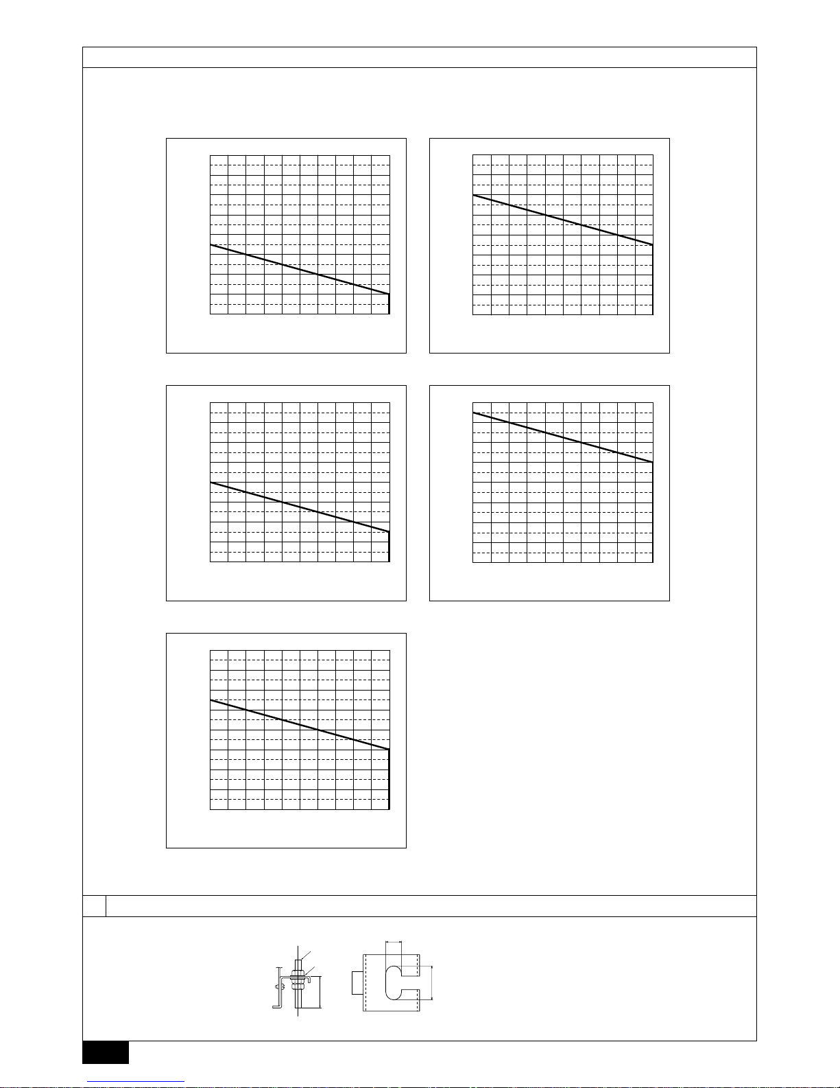
[Fig. 2.4.3]
2.4
3
3.2
[Fig. 3.2.1]
1
A
B
A
1 Hanging method
A: Min. 30 mm
A Hanging bolt ø10 (field supply)
B Washer (field supply)
PURY-P200/250/300YHM-A, PURY-EP200YHM-A
PQRY-P200/250/300YHM-A
●Restrictions on piping length
PURY-P600/650YSHM-A, PURY-EP600YSHM-A
PURY-P350/400/450Y(S)HM-A, PURY-EP250/300YHM-A
PURY-P700/750/800YSHM-A
PURY-P500/550YSHM-A, PURY-EP400/450/500/550YSHM-A(1)
PQRY-P400/450/500/550/600YSHM-A
400
500
600
700
800
900
1000
A
800
900
1000
200
300
400
500
600
700
800
900
1000
10 20 30 40 50 60 70 80 90 100 110
A
200
300
10 20 30 40 50 60 70 80 90 100 110
400
500
600
700
800
900
1000
200
300
400
500
600
700
800
10 20 30 40 50 60 70 80 90 100 110
A
900
1000
A
200
300
400
500
600
700
A
10 20 30 40 50 60 70 80 90 100 110
10 20 30 40 50 60 70 80 90 100 110
B
B
B
B
B
300
200
4
14
30
(Top view)
A Total piping length (m) B Piping length between outdoor unit and BC controller (m)
Page 5
5
4.1
[Fig. 4.1.1]
4
B
C
D
E
F
A
A
F
A
A Indoor unit connecting port
B Cutting point : ø9.52 (Liquid side) or ø15.88 (Gas side)
(Indoor unit model : bigger than P50)
C Cutting point : ø6.35 (Liquid side) or ø12.7 (Gas side)
(Indoor unit model : P50 or smaller)
D Cut the piping at the cutting point
E Have pipe expansion of indoor unit connecting port
F Field pipe
Note:
Remove burr after cutting the piping to prevent entering the piping.
Check that there is no crack at the pipe expansion part.
A To outdoor unit (MAIN BC CONTROLLER)
B End connection (brazing)
C BC controller (MAIN BC CONTROLLER / SUB BC CONTROLLER)
D Reducer E Indoor unit
F Less than 50
G Combined piping kit (Model name: CMY-R160-J1)
H Twinning pipe (Model name: CMY-Y102S-G2)
I Up to three units for 1 branch hole; total capacity: below 80 (but same in cooling/
heating mode)
E
EE
EEIE
A
B
G
*2
H
*1
D
63-80 100-250 *3
C
F
Total capacity of indoor units Liquid line Gas line
Below 140 ø15.88
141 to 200 ø9.52 ø19.05
201 to 250 ø22.2
*1. For connecting 15 to 50 type indoor units
Have pipe expansion of indoor unit connecting port by cutting the piping at the
cutting point which depends on the indoor unit capacity.
Note:
Remove burr after cutting the piping to prevent entering the piping.
Check that there is no crack at the pipe expansion part.
*2. To connect a unit with a capacity of higher than 81.
After combining two branches using an optionally available piping kit (CMY-R160J1), connect indoor units.
*3. Connection of plural indoor units with one connection (or joint pipe)
•Total capacity of connectable indoor units: Less than 80 (Less than 250 with
joint pipe)
• Number of connectable indoor units: Maximum 3 Sets
•Twinning pipe: Use the twinning pipe for CITY MULTI Y Series (CMY-Y102S-G2)
• Selection of refrigerant piping
Select the size according to the total capacity of indoor units to be installed
downstream.
*1 Use the supplied pipe.
Outdoor unit side
PURY-(E) P400
PQRY-P400
PURY-(E) P450
PQRY-P450
PURY-(E) P500
PQRY-P500
PURY-(E) P550
PQRY-P550
PURY-(E) P600
PQRY-P600
PURY-P650
PURY-P700
PURY-P750
PURY-P800
BC CONTROLLER/MAIN BC CONTROLLER SUB BC CONTROLLER
Unit model Model name
High pressure
side
Low pressure
side
Model name
Total capacity
of indoor units
High pressure
(gas) side
Low pressure
(gas) side
Liquid side
PURY-(E) P200
PQRY-P200
PURY-(E) P250
PQRY-P250
PURY-(E) P300
PQRY-P300
PURY-P350
Indoor unit side
(BC CONTROLLER)
CMB-P104V-G1
CMB-P105V-G1
CMB-P106V-G1
CMB-P108V-G1
CMB-P1010V-G1
CMB-P1013V-G1
CMB-P1016V-G1
(MAIN BC
CONTROLLER)
CMB-P108V-GA1
CMB-P1010V-GA1
CMB-P1013V-GA1
CMB-P1016V-GA1
(MAIN BC
CONTROLLER)
CMB-P1016V-HA1
When a system that has more than 16 branching points, use BC controllers (main and
sub) to connect the pipes.
CMB-P104V-GB1
CMB-P108V-GB1
CMB-P1016V-HB1
ø15.88*1
(Brazing)
ø19.05
(Brazing)
ø19.05*1
(Brazing)
ø22.2
(Brazing)
ø28.58*1
(Brazing)
ø28.58
(Brazing)
ø9.52 or ø6.35
(Brazing)
ø19.05*1
(Brazing)
ø22.2
(Brazing)
ø28.58*1
(Brazing)
ø28.58
(Brazing)
ø34.93*1
(Brazing)
ø15.88 or ø12.7
(Brazing)
below 200
ø15.88*1
(Brazing)
ø19.05*1
(Brazing)
ø9.52
(Brazing)
201~300
ø19.05
(Brazing)
ø22.2
(Brazing)
301~350
351~400
ø22.2*1
(Brazing)
ø28.58*1
(Brazing)
401~450
ø9.52 or ø6.35
(Brazing)
ø15.88 or ø12.7
(Brazing)
ø12.7*1
(Brazing)
ø15.88*1
(Brazing)
[Fig. 4.1.2]
Page 6
6
[Fig. 4.4.1]
4.4
1
A
A
B
C
B
A: 25 cm B: 1.5 – 2 m
A Downward pitch of more than 1/100
B Insulating material C Supporting bracket
D Drain discharge port E Drain hose (200 mm long, accessory)
F Tie band (accessory) G Hose band (accessory)
BB
A
D
3
C
VP-30
A BC controller B Indoor unit
C Collecting pipe D Please ensure this length is at least 10 cm.
[Fig. 4.4.2]
[Fig. 5.0.1]
A Control box
B Power source wiring
C ø21 hole (closed rubber bushing)
D Tr ansmission wiring
5
B
A
C
D
VP-25
2
D
E
G
F
4.2
[Fig. 4.2.1]
F
E
D
A
C
B
4.3
[Fig. 4.3.1]
A Cut here
B Remove brazed cap
B
A
A Locally procured insulating mater ial
for pipes
B Bind here using band or tape.
c Do not leave any opening.
D Lap margin: more than 40
E Insulating material (field supply)
F Unit side insulating material
Page 7
7
GBDFEINLPGRRUTRCZSVSLHGPO
Contents
1. Safety precautions
1.1. Before installation and electric work
s Before installing the unit, make sure you read all the “Safety
precautions”.
s The “Safety precautions” provide very important points re-
garding safety. Make sure you follow them.
Symbols used in the text
Warning:
Describes precautions that should be observed to prevent danger of injury
or death to the user.
Caution:
Describes precautions that should be observed to prevent damage to the
unit.
Symbols used in the illustrations
: Indicates an action that must be avoided.
: Indicates that important instructions must be followed.
: Indicates a part which must be grounded.
: Beware of electric shock (This symbol is displayed on the main unit label.)
<Color: Yellow>
Warning:
Carefully read the labels affixed to the main unit.
HIGH VOL T AGE W ARNING:
• Control box houses high-voltage parts.
• When opening or closing the front panel of the control box, do not let it
come into contact with any of the internal components.
• Before inspecting the inside of the control box, turn off the power, keep
the unit off for at least 10 minutes.
Warning:
• Ask the dealer or an authorized technician to install the air conditioner.
- Improper installation by the user may result in water leakage, electric shock,
or fire.
• Install the unit at a place that can withstand its weight.
- Failure to do so may cause the unit to fall down, resulting in injuries and
damage to the unit.
• Use the specified cables for wiring. Make the connections securely so
that the outside force of the cable is not applied to the terminals.
- Inadequate connection and fastening may generate heat and cause a fire.
• Prepare for earthquakes and install the unit at the specified place.
- Improper installation may cause the unit to fall down and result in injury and
damage to the unit.
• Always use accessories specified by Mitsubishi Electric.
- Ask an authorized technician to install the accessories. Improper installation
by the user may result in water leakage, electric shock, or fire.
• Never repair the unit. If the air conditioner must be repaired, consult the
dealer.
- If the unit is repaired improperly, water leakage, electric shock, or fire may
result.
• If refrigerant gas leaks during installation work, ventilate the room.
- If the refrigerant gas comes into contact with a flame, poisonous gases will
be released.
• Install the air conditioner according to this Installation Manual.
- If the unit is installed improperly, water leakage, electric shock, or fire may
result.
• Have all electric work done by a licensed electrician according to “Electric Facility Engineering Standard” and “Interior Wire Regulations”and
the instructions given in this manual and always use a dedicated power
supply.
- If the power source capacity is inadequate or electric work is performed im-
properly, electric shock and fire may result.
• Securely install the cover of control box.
- If the cover is not installed properly, dust or water may enter the outdoor unit
and fire or electric shock may result.
• When installing and moving the air conditioner to another site, do not
charge it with a refrigerant different from the refrigerant specified on the
unit.
- If a different refrigerant or air is mixed with the original refrigerant, the refrig-
erant cycle may malfunction and the unit may be damaged.
• If the air conditioner is installed in a small room, measures must be taken
to prevent the refrigerant concentration from exceeding the safety limit if
the refrigerant should leak.
- Consult the dealer regarding the appropriate measures to prevent the safety
limit from being exceeded. Should the refrigerant leak and cause the safety
limit to be exceeded, hazards due to lack of oxygen in the room could result.
• When moving and reinstalling the air conditioner, consult the dealer or
an authorized technician.
- If the air conditioner is installed improperly, water leakage, electric shock, or
fire may result.
• After completing installation work, make sure that refrigerant gas is not
leaking.
- If the refrigerant gas leaks and is exposed to a fan heater, stove, oven, or
other heat source, it may generate noxious gases.
• Do not reconstruct or change the settings of the protection devices.
- If the pressure switch, thermal switch, or other protection device is shorted
or operated forcibly, or parts other than those specified by Mitsubishi Electric
are used, fire or explosion may result.
•To dispose of this product, consult your dealer.
• The installer and system specialist shall secure safety against leakage
according to local regulation or standards.
- Choose the appropriate wire size and the switch capacities for the main power
supply described in this manual if local regulations are not available.
• Pay special attention to the place of installation, such as basement, etc.
where refrigeration gas can accumulate, since refrigerant is heavier than
the air.
1.2. Precautions for devices that use R410A
refrigerant
Caution:
• Do not use existing refrigerant piping.
- The old refrigerant and refrigerant oil in the existing piping contains a large
amount of chlorine which may cause the refrigerant oil of the new unit to
deteriorate.
- R410A is a high-pressure refrigerant and can cause the existing piping to
burst.
• Use refrigerant piping made of phosphorus deoxidized copper and copper alloy seamless pipes and tubes. In addition, be sure that the inner
and outer surfaces of the pipes are clean and free of hazardous sulphur,
oxides, dust/dirt, shaving particles, oils, moisture, or any other contaminant.
- Contaminants on the inside of the refrigerant piping may cause the refriger-
ant residual oil to deteriorate.
• Store the piping to be used during installation indoors and keep both
ends of the piping sealed until just before brazing. (Store elbows and
other joints in a plastic bag.)
- If dust, dirt, or water enters the refrigerant cycle, deterioration of the oil and
compressor failure may result.
• Apply a small amount of ester oil, ether oil, or alkyl benzene to flares. (for
indoor unit)
- Infiltration of a large amount of mineral oil may cause the refrigerant oil to
deteriorate.
1. Safety precautions ...................................................................................... 7
1.1. Before installation and electric work .......................................... 7
1.2. Precautions for devices that use R410A refrigerant .................. 7
1.3. Before installation ...................................................................... 8
1.4. Before installation (relocation) - electrical work ......................... 8
1.5. Before starting the test run ........................................................ 8
2. Selecting an installation site ....................................................................... 8
2.1. About the product ...................................................................... 8
2.2. Installation site ........................................................................... 8
2.3. Securing installation and service space .................................... 9
2.4. Checking the installation site ..................................................... 9
3. Installing BC controller .............................................................................. 10
3.1. Checking the accessories with BC controller .......................... 10
3.2. Installing BC controllers ........................................................... 10
4. Connecting refrigerant pipes and drain pipes ........................................... 10
4.1. Connecting refrigerant pipes ................................................... 10
4.2. Refrigerant piping work ........................................................... 11
4.3. Insulating refrigerant pipes ...................................................... 12
4.4. Drain piping work ..................................................................... 12
5. Electrical work ........................................................................................... 12
6. Setting addresses and operating units ..................................................... 12
7. Test run ..................................................................................................... 12
Page 8

8
GBDFEINLPGRRUTRCZSVSLHGPO
• Use liquid refrigerant to fill the system.
- If gas refrigerant is used to fill the system, the composition of the refrigerant
in the cylinder will change and performance may drop.
• Do not use a refrigerant other than R410A.
- If another refrigerant (R22, etc.) is mixed with R410A, the chlorine in the
refrigerant may cause the refrigerant oil to deteriorate.
• Use a vacuum pump with a reverse flow check valve.
- The vacuum pump oil may flow back into the refrigerant cycle and cause the
refrigerant oil to deteriorate.
• Do not use the following tools that are used with conventional refrigerants.
(Gauge manifold, charge hose, gas leak detector, reverse flow check valve,
refrigerant charge base, refrigerant recovery equipment)
- If the conventional refrigerant and refrigerant oil are mixed in the R410A, the
refrigerant may deteriorate.
- If water is mixed in the R410A, the refrigerant oil may deteriorate.
- Since R410A does not contain any chlorine, gas leak detectors for conven-
tional refrigerants will not react to it.
• Do not use a charging cylinder.
- Using a charging cylinder may cause the refrigerant to deteriorate.
• Do not use antioxidant or leak-detection additive.
• Be especially careful when managing the tools.
- If dust, dirt, or water gets into the refrigerant cycle, the refrigerant may dete-
riorate.
1.3. Before installation
Caution:
• Do not install the unit where combustible gas may leak.
- If the gas leaks and accumulates around the unit, an explosion may result.
• Do not use the air conditioner where food, pets, plants, precision instruments, or artwork are kept.
- The quality of the food, etc. may deteriorate.
• Do not use the air conditioner in special environments.
- Oil, steam, sulfuric smoke, etc. can significantly reduce the performance of
the air conditioner or damage its parts.
• When installing the unit in a hospital, communication station, or similar
place, provide sufficient protection against noise.
- Inverter equipment, private power generator, high-frequency medical equip-
ment, or radio communication equipment may cause the air conditioner to
operate erroneously, or fail to operate. On the other hand, the air conditioner
may affect such equipment by creating noise that disturbs medical treatment
or image broadcasting.
• Do not install the unit on or over things that are subject to water damage.
- When the room humidity exceeds 80 % or when the drain pipe is clogged,
condensation may drip from the indoor unit or BC controller. Perform collective drainage work together with the outdoor unit, as required.
1.4. Before installation (relocation) - electrical work
Caution:
• Ground the unit.
- Do not connect the ground wire to gas or water pipes, lightning rods, or
telephone ground lines. Improper grounding may result in electric shock.
• Install the power cable so that tension is not applied to the cable.
-Tension may cause the cable to break and generate heat and cause a fire.
• Install a leak circuit breaker, as required.
- If a leak circuit breaker is not installed, electric shock may result.
• Use power line cables of sufficient current carrying capacity and rating.
- Cables that are too small may leak, generate heat, and cause a fire.
• Use only a circuit breaker and fuse of the specified capacity.
-A fuse or circuit breaker of a larger capacity, or the use of substitute simple
steel or copper wire may result in a general unit failure or fire.
• Do not wash the air conditioner units.
-Washing them may cause an electric shock.
• Be careful that the installation base is not damaged by long use.
- If the damage is left uncorrected, the unit may fall and cause personal injury
or property damage.
• Install the drain piping according to this Installation Manual to ensure
proper drainage. Wrap thermal insulation around the pipes to prevent
condensation.
- Improper drain piping may cause water leakage causing damage to furniture
and other possessions.
• Be very careful about transporting the product.
- One person should not carry the product. Its weight is in excess of 20 kg.
- Some products use PP bands for packaging. Do not use any PP bands as a
means of transportation. It is dangerous.
• Safely dispose of the packing materials.
- Packing materials, such as nails and other metal or wooden parts, may cause
stabs or other injuries.
-Tear apart and throw away plastic packaging bags so that children will not
play with them. If children play with a plastic bag which has not been torn
apart, they face the risk of suffocation.
1.5. Before starting the test run
Caution:
•Turn on the power at least 12 hours before starting operation.
- Starting operation immediately after turning on the main power switch can
result in irreversible damage to internal parts. Keep the power switch turned
on during the operational season.
• Do not touch the switches with wet fingers.
-Touching a switch with wet fingers can result in an electric shock.
• Do not touch the refrigerant pipes during and immediately after operation.
- During and immediately after operation, the refrigerant pipes may be hot or
cold, depending on the condition of the refrigerant flowing through the refrigerant piping, compressor, and other refrigerant cycle parts. Your hands may
suffer burns or frostbite if you touch the refrigerant pipes.
• Do not operate the air conditioner with the panels and guards removed.
- Rotating, hot, or high-voltage parts can cause injuries.
• Do not turn off the power immediately after stopping operation.
- Always wait at least 5 minutes before turning off the power. Otherwise, drain-
age water leakage or mechanical failure of sensitive parts may occur.
2. Selecting an installation site
2.1. About the product
• This unit uses R410A-type refrigerant.
• Piping for systems using R410A may be different from that for systems using
conventional refrigerant because the design pressure in systems using R410A
is higher. Refer to the Data Book for more information.
• Some of the tools and equipment used for installation with systems that use
other types of refrigerant cannot be used with the systems using R410A. Refer
to the Data Book for more information.
• Do not use the existing piping, as it contains chlorine, which is found in conventional refrigerating machine oil and refrigerant. This chlorine will deteriorate
the refrigerant machine oil in the new equipment. The existing piping must not
be used as the design pressure in systems using R410A is higher than that in
the systems using other types of refrigerant and the existing pipes may burst.
2.2. Installation site
• Install the unit in a place not exposed to rain. The BC controller is designed to
be installed indoors.
• Install the unit with adequate space around it for servicing.
• Do not install the unit in a place that would result in the piping length restric-
tions being exceeded.
• Install the unit in a place not exposed to direct radiant heat from other heat sources.
• Do not install the unit in any oily steamy place or near any machine that gener-
ates high frequencies. Doing so may cause a risk of fire, erroneous operation
or dew drop.
• Install the unit in a location where the noise from the unit will not be a problem.
(Install indoor unit and BC controller at least 5 m away from each other when
installed in a space with low background noise, e.g., hotel rooms).
• Allow enough space and access to ensure water piping, refrigerant piping and
electrical wiring can be easily connected.
• Avoid places exposed to the generation, inflow, accumulation or leakage of
flammable and sulfuric gases.
• Ensure a downward gradient of at least 1/100 for drain piping.
• Properly install the unit on a stable, load-bearing surface.
Page 9

9
GBDFEINLPGRRUTRCZSVSLHGPO
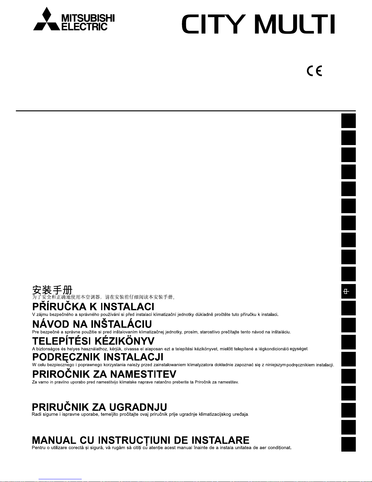
1. For hanging from the ceiling [Fig. 2.2.1] (P.2)
• Provide an inspection hole 450 mm square in the ceiling surface as shown in
[Fig. 2.3.1] (P.2).
• Install the unit in a suitable location (such as in the ceiling of a corridor or in the
bathroom etc) away from places regularly occupied. Avoid installing in the center
of a room.
• Ensure a pull out strength of at least 60 kg per bolt for hanging bolts.
• Be sure to install the BC controller horizontally.
Warning:
Be sure to install the unit in a place that can sustain the entire weight.
If there is a lack of strength, it may cause the unit to fall down, resulting in an
injury.
Caution:
Be sure to install the unit horizontally.
2.3. Securing installation and service space
1. For hanging from the ceiling
(This is a reference view showing the least installation space.)
[Fig. 2.3.1] (P.2)
<A> Top view <B> Front view
A Inspection hole B On the side of outdoor unit piping
C Control box D On the side of indoor unit piping
*1 Dimensions with which pipe connection can be handled at site
Notes:
*1 Refer to “Restrictions on piping length” on P . 4.
*2 Please refer to the figure “Distance between BC controller and farthest
Indoor unit” when the distance between BC controller and farthest indoor unit exceeds 40 m. (Not applicable to the P250 model indoor unit)
*3 The values in the parentheses show the maximum piping length to be
followed when the connection capacity of the indoor unit is 200 or more.
*4 In the system to which indoor units of the P200 model or above are con-
nected, neither a branch joint nor a branch header may be used.
*5 Do not connect the P200 or P250 models of indoor units and other mod-
els of indoor units at the same port.
*6 In the system to which indoor units of the P100 through P140 models are
connected, merge the two ports before connecting them. (Set DIP SW4-6
on the BC controller to ON.)
*7 It is possible to connect the P100 through P140 models of indoor units to
a single port. (Set DIP SW4-6 to OFF.) Note that the cooling capacity will
somewhat decrease. (The factory setting for DIP SW4-6 is OFF.)
*8 Indoor units that are connected to the same branch joint cannot be simul-
taneously operated in different operation modes.
Model name A B
CMB-P104V-G1
CMB-P105V-G1
CMB-P106V-G1 648
CMB-P108V-G1
CMB-P1010V-G1
CMB-P1013V-G1
1098
CMB-P1016V-G1
CMB-P108V-GA1
CMB-P1010V-GA1
1110 200
CMB-P1013V-GA1
CMB-P1016V-GA1
CMB-P104V-GB1
648
CMB-P108V-GB1
CMB-P1016V-HA1 1110 200
CMB-P1016V-HB1 1098
-
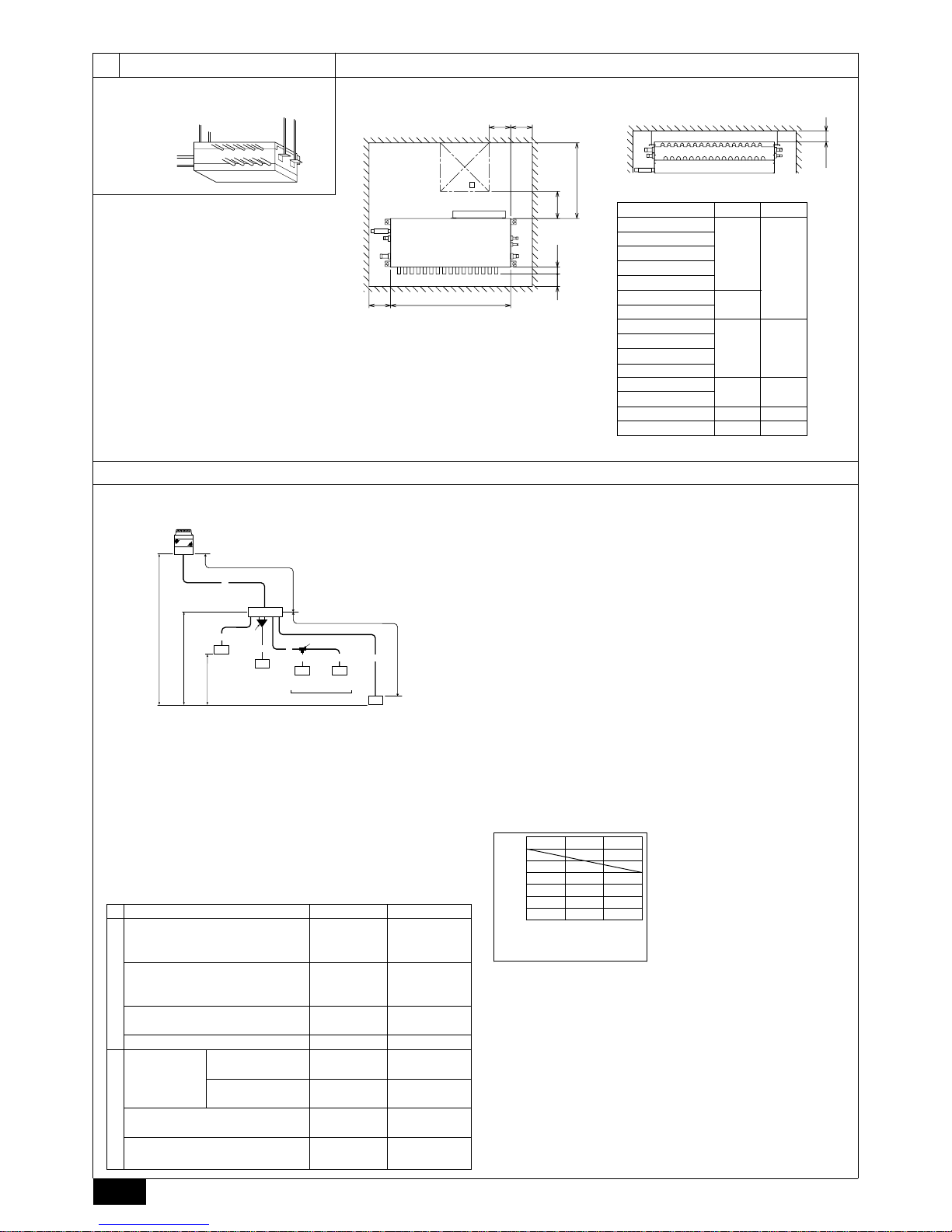
Length
(Unit: m)
Item Piping portion Allowable value
A+B+a+b
Total piping length
+c+d+e
Longest piping length A+e
Between outdoor unit and
A Below 110
BC controller
Between indoor units and BC controller e Below 40 *2
Above outdoor unit H Below 50
Below outdoor unit H1 Below 40
Between indoor units and BC controller h1
Below 15
(Below 10)*3
Between indoor units h2
Below 15
(Below 10)*3
Difference of elevation
Between
indoor and
outdoor units
Not to exceed the
maximum refrigerant piping length *1
165 m or less
(Equivalent length
of 190 m or less)
2.4. Checking the installation site
Check that the difference of elevation between indoor and outdoor units and the
length of refrigerant piping are within the following limitations.
1. CMB-P104, 105, 106, 108, 1010, 1013, 1016G1 (In the case the outdoor unit
is 14-hp (P350 model) or less, and 16 or fewer ports are used.)
[Fig. 2.4.1] (P.2)
A Outdoor unit B BC controller
C Indoor unit D P100 - P250 model: 2 ports merged.
E Less than H=50 m (when the outdoor unit is higher than the indoor unit)
F Less than H1=40 m (when the outdoor unit is lower than the indoor unit)
G Twinning pipe (for Y Series) CMY-Y102S-G2
H Combined pipe (CMY-R160-J1: optional)
I Less than 110 m J Less than 40 m
K Up to three units for 1 branch hole
Total capacity: less than 80 (but same in cooling/heating mode)
L Less than h1=15 m (10 m or less for 200, 250 unit type)
M Less than h2=15 m
Distance between BC controller
and farthest indoor unit
Height difference between
BC controller and farthest
indoor unit (m)
15105
20
10
0
0
Distance between BC contoroller
and farthest indoor unit (m)
70
60
50
40
30
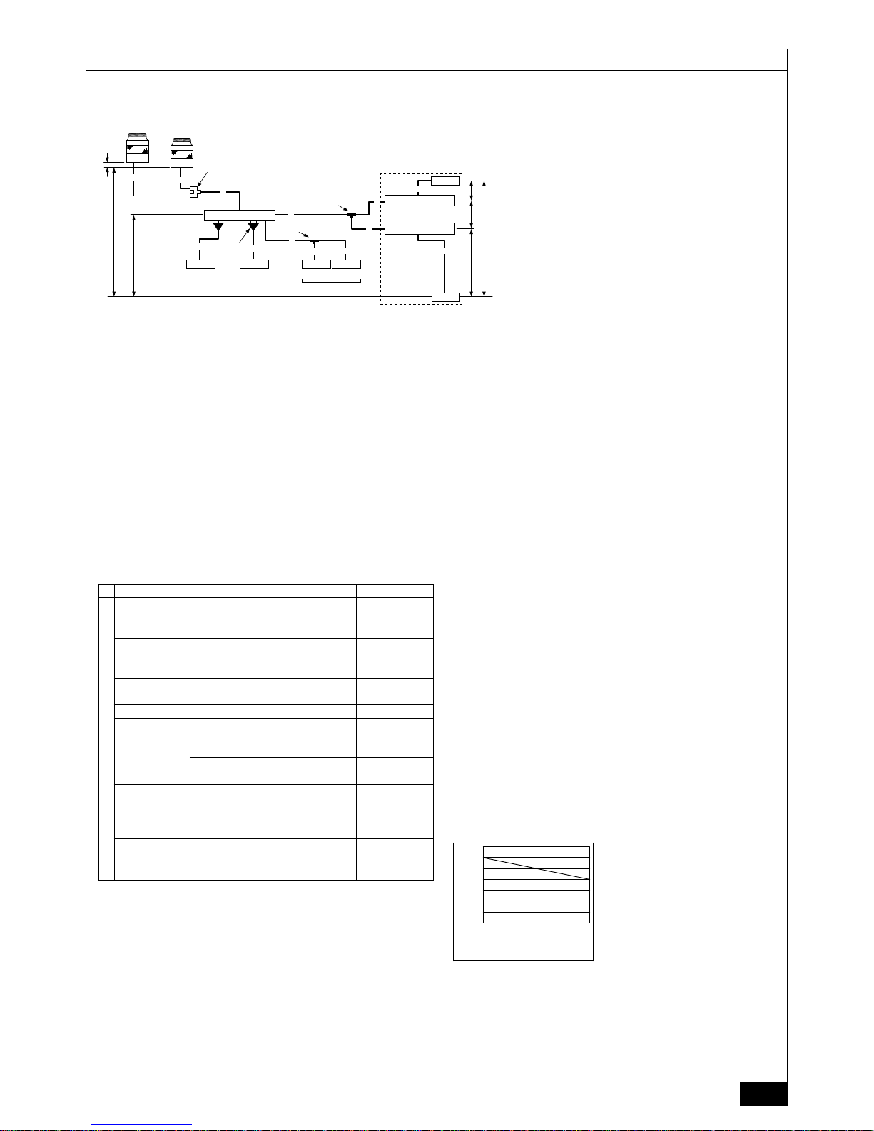
2. CMB-P108, 1010, 1013, 1016GA1, P104, 108GB1 (GA1: In the case the outdoor unit is 26-hp (P650 model) or less.)
CMB-P1016HA1, 1016HB1 (HA1: In the case the outdoor unit is 28-hp
(P700 model) or more.)
[Fig. 2.4.2] (P.3)
A Outdoor unit B MAIN BC controller
C SUB BC controller D Indoor unit
E The twinning kit is connected inside the outdoor unit on the low-pressure side.
When outdoor units of different capacities are connected, connect the twinning
kit to the unit with a higher capacity.
F Twinning pipe (for R2 series) CMY-R100VBK, CMY-R200VBK
(for WR2 series) CMY-Q100VBK
G Twinning pipe (for Y series) CMY-Y202-G2, CMY-Y102L-G2, CMY-Y102S-G2
H Twinning pipe (CMY-R160-J1: optional)
I Twinning pipe (for Y series) CMY-Y102S-G2
J P100 - P250 model: 2 ports merged
K Maximum of 3 units per a pair of ports
Total capacity of 80 or below
All units connected to the same port must be in the same operation mode.
L Less than H=50 m (when the outdoor unit is higher than the indoor unit)
M Less than H1=40 m (when the outdoor unit is lower than the indoor unit)
N Less than h1=15 m (10 m or less for 200, 250 unit type)
O Less than h2=15 m
Page 10

10
GBDFEINLPGRRUTRCZSVSLHGPO
3.1. Checking the accessories with BC controller
The following items are supplied with each BC controller.
Distance between MAIN BC controller
and farthest indoor unit
Height difference between
MAIN BC controller and
farthest indoor unit (m)
15105
20
10
0
0
Distance between MAIN BC controller
and farthest indoor unit (m)
70
60
50
40
30
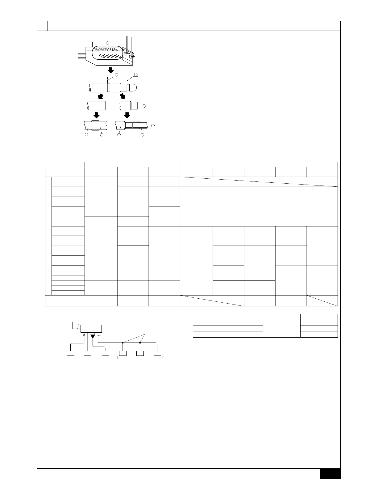
4.1. Connecting refrigerant pipes
1. Connect the liquid and gas pipes of each indoor unit to the same (correct) end
connection numbers as indicated on the indoor unit connection section of each
BC controller. If connected to wrong end connection numbers, there will be no
normal operation.
2. List indoor unit model names in the name plate on the BC controller control
box (for identification purposes), and BC controller end connection numbers
and address numbers in the name plate on the indoor unit side.
3. If the number of ports is greater than the number of indoor units to be connected,
use any ports.
Seal unused end connections using cover caps just as they were capped when
shipped from the factory. Not replacing on end cap will lead to refrigerant leak-age.
4. When using CMY-Y102S-G2, CMY-Y102L-G2, or CMY-Y202-G2, connect it
horizontally.
5. Be sure to have pipe expansion of indoor unit connecting port by cutting the
piping at the cutting point which depends on the indoor unit capacity.
Note:
Remove burr after cutting the piping to prevent entering the piping.
Check that there is no crack at the pipe expansion part.
[Fig. 4.1.1] (P.5)
A Indoor unit connecting port
B Cutting point : ø 9.52 (Liquid side) or ø15.88 (Gas side)
(Indoor unit model : bigger than P50)
C Cutting point : ø 6.35 (Liquid side) or ø12.7 (Gas side)
(Indoor unit model : P50 or smaller)
D Cut the piping at the cutting point
E Have pipe expansion of indoor unit connecting port
F Field pipe
4. Connecting refrigerant pipes and drain pipes
3.2. Installing BC controllers
Installing hanging bolts
Install locally procured hanging bolts (threaded rod) following the procedure given
in the figure. The hanging bolt size is ø10 (M10 screw).
To hang the unit, use a lifting machine to lift and pass it through the hanging bolts.
Suspension bracket has an oval hole. Use a large diameter washer.
[Fig. 3.2.1] (P.4)
1 Hanging method
A: Min.30 mm
A Hanging bolt ø10 (field supply) B Washer (field supply)
s Be sure to install the BC controller horizontally, using a level. If the
controller is installed at an angle, drain water may leak out. If the controller
is slanted, loosen the fixing nuts on the hanging brackets to adjust its
position.
Caution:
Be sure to install the unit horizontally.
Length
(Unit: m)
Item Piping portion Allowable value
F+G+A+B+C
Total piping length +D+E+a+b
+c+d+e+f
Longest piping length F(G)+A+C+E+f
Between outdoor unit and
F(G)+A Below 110
BC controller
Between indoor units and BC controller
B+d or C+D+e or C+E+f
Below 40 *2
Between outdoor units F+G Below 5
Above outdoor unit H Below 50
Below outdoor unit H’ Below 40
Between indoor units and BC controller h1
Below 15
(Below 10)*3
Between indoor units h2
Below 15
(Below 10)*3
Between BC controller (main or sub)
h3 Below 15
and BC controller (sub)
Between outdoor units h4 Below 0.1
Difference of elevation
Between
indoor and
outdoor units
Not to exceed the
maximum refrigerant piping length *1
165 m or less
(Equivalent length
of 190 m or less)
Notes:
A system that has more than 16 branching points requires 2 to 3 BC control-
lers (main and sub) and 3 pipes to connect the main and the sub BC controllers.
*1 Refer to “Restrictions on piping length” on P . 4.
*2 Please refer to the figure “Distance between main BC controller and far-
thest Indoor unit” when the distance between main BC controller and
farthest indoor unit exceeds 40 m. (Not applicable to the P250 model
indoor unit)
*3 The values in the parentheses show the maximum piping length to be
followed when the connection capacity of the indoor unit is 200 or more.
*4 In the system to which indoor units of the P200 model or above are con-
nected, neither a branch joint nor a branch header may be used.
*5 When connecting two sub BC controllers, the total piping length must be
equal to or less than the maximum length as listed in on the left.
*6 When connecting two sub BC controllers, install them in parallel.
*7 In the system to which indoor units of the P100 through P140 models are
connected, merge the two ports before connecting them. (Set DIP SW4-6
on the BC controller to ON.)
*8 It is possible to connect the P100 through P140 models of indoor units to
a single port. (Set DIP SW4-6 to OFF.) Note that the cooling capacity will
somewhat decrease. (The factory setting for DIP SW4-6 is OFF.)
*9 When the outdoor unit is 28-hp (P700 model) or more, use the HA-type
main BC controller. The G-type BC controller cannot be connected to the
models between 16-hp (P400 model) and 26-hp (P650 model), and the Gand GA-type BC controllers cannot be connected to the 28-hp (P650
model) or more.
*10 For Sub BC controller GB type, the connectable indoor unit capacities
may sum to equal that of a P350 unit or less. However, if two sub controllers are used the TOTAL sum of connectable units connected to BOTH
sub controllers must also not exceed that of a P350 unit.
For sub BC controller HB type, the connectable indoor unit capacities
may sum to equal that or a P350 unit or less. However, if two sub controllers are used the TOTAL sum of connectable units connected to BOTH
sub controllers must also not exceed that of a P450 unit.
*11 Indoor units that are connected to the same branch joint cannot be si-
multaneously operated in different operation modes.
*12 Do not connect the P200 or P250 models of indoor units and other mod-
els of indoor units at the same port.
3. Installing BC controller
1 Drain hose
2 Tie band
3 Hose band
4 Refrigerant
connection pipe
Item
Qty
CMBP104V-G1
P105V-G1
P106V-G1
P108V-G1
P1010V-G1
P1013V-G1
P1016V-G1
1
1
1
3
Model name
CMBP108V-GA1
P1010V-GA1
P1013V-GA1
P1016V-GA1
1
1
1
3
CMBP104V-GB1
P108V-GB1
1
1
1
8
CMBP1016V-HA1
1
1
1
1
CMBP1016V-HB1
1
1
1
8
[Fig. 2.4.3] (P.4)
A Total piping length (m)
B Piping length between controller unit and BC controller (m)
Page 11

11
GBDFEINLPGRRUTRCZSVSLHGPO
A To outdoor unit (MAIN BC CONTROLLER)
B End connection (brazing)
C BC controller (MAIN BC CONTROLLER/SUB BC CONTROLLER)
D Reducer E Indoor unit
F Less than 50
G Combined piping kit (Model name: CMY-R160-J1)
H Twinning pipe (Model name: CMY-Y102S-G2)
I Up to three units for 1 branch hole; total capacity: below 80 (but same in cooling/
heating mode)
The size of BC controller’s branch piping is for 63 to 140 type indoor units.
Therefore, if you want to connect indoor units other than the above, connect piping
following the procedures below.
*1. For connecting 15 to 50 type indoor units
Have pipe expansion of indoor unit connecting port by cutting the piping at the
cutting point which depends on the indoor unit capacity.
Note:
Remove burr after cutting the piping to prevent entering the piping.
Check that there is no crack at the pipe expansion part.
*2. To connect a unit with a capacity of higher than 81.
After combining two branches using an optionally available piping kit (CMY-R160J1), connect indoor units.
*3. Connection of plural indoor units with one connection (or joint pipe)
• Total capacity of connectable indoor units: Less than 80 (Less than 250 with
joint pipe)
• Number of connectable indoor units: Maximum 3 Sets
• Twinning pipe: Use the twinning pipe for CITY MULTI Y Series (CMY-Y102S-
G2)
• Selection of refrigerant piping
Select the size according to the total capacity of indoor units to be installed
downstream.
Total capacity of indoor units Liquid line Gas line
Below 140 ø15.88
141 to 200 ø9.52 ø19.05
201 to 250 ø22.2
6. Be sure to use non-oxidative brazing where necessary. If you do not use nonoxidative brazing, it may clog the pipes.
While under a nitrogen purge, braze the indoor unit connecting port before
brazing the outdoor unit connecting port of BC controller.
When brazing the indoor unit connecting port, supply a nitrogen gas into the
outdoor unit connecting port of BC controller.
When brazing the outdoor unit connecting port of BC controller, supply a nitrogen
gas into the pipe between the outdoor unit and BC controller.
7. After completing pipe connection, support the pipes to ensure that load is not
imparted to the BC controller’s end connections (particularly to the gas pipes
of indoor units).
Warning :
When installing and moving the unit, do not charge it with refrigerant other
than the refrigerant (R410A) specified on the unit.
- Mixing of a different refrigerant, air, etc. may cause the refrigerant cycle to mal-
function and result in severe damage.
Caution:
•
Use refrigerant piping made of phosphorus deoxidized copper and copper alloy seamless pipes and tubes. In addition, be sure that the inner and
outer surfaces of the pipes are clean and free of hazardous sulphur , oxides,
dust/dirt, shaving particles, oils, moisture, or any other contaminant.
-
R410A is a high-pressure refrigerant and can cause the existing piping to burst.
• Store the piping to be used during installation indoors and keep both
ends of the piping sealed until just before brazing. (Store elbows and
other joints in a plastic bag.)
- If dust, dirt, or water enters the refrigerant cycle, deterioration of the oil and
compressor failure may result.
• Apply a small amount of ester oil, ether oil, or alkyl benzene to flares. (for
indoor unit)
- Infiltration of a large amount of mineral oil may cause the refrigerant oil to
deteriorate.
• Do not vent R410A into the atmosphere.
• R410A is a Fluorinated Greenhouse gas, covered by the Kyoto Protocol
with a Global Warming Potential (GWP) = 1975.
*1 Use the supplied pipe.
[Fig. 4.1.2] (P.5)
Note:
Be sure to use non-oxidative brazing.
4.2. Refrigerant piping work
After connecting the refrigerant pipes of all indoor and outdoor units with the outdoor units’ stop valves remained fully closed, evacuate vacuum from the outdoor
units’ stop valve service ports.
After completing the above, open the outdoor units’ stop valves. This connects the
refrigerant circuit (between outdoor and BC controller) completely.
How to handle stop valves is described on each outdoor unit.
Notes:
• After pipe connection, be sure to check that there is no gas leakage,
using a leak detector or soap-and-water solution.
• Before brazing the refrigerant piping, always wrap the piping on the main
body, and the thermal insulation piping, with damp cloths to prevent heat
shrinkage and burning the thermal insulation tubing. Take care to ensure
that the flame does not come into contact with the main body itself.
• Do not use leak-detection additives.
Warning:
Do not mix anything other than the specified refrigerant (R410A) into the
refrigerating cycle when installing or moving. Mixing air may cause the refrigerating cycle to reach abnormally high temperature, resulting in burst pipes.
Caution:
Cut the tip of the outdoor unit piping, remove the gas, and then remove the
brazed cap.
[Fig. 4.2.1] (P.6)
A Cut here B Remove brazed cap
1. Size of BC controller’s end connection piping
Outdoor unit side
PURY-(E) P400
PQRY-P400
PURY-(E) P450
PQRY-P450
PURY-(E) P500
PQRY-P500
PURY-(E) P550
PQRY-P550
PURY-(E) P600
PQRY-P600
PURY-P650
PURY-P700
PURY-P750
PURY-P800
BC CONTROLLER/MAIN BC CONTROLLER SUB BC CONTROLLER
Unit model Model name
High pressure
side
Low pressure
side
Model name
Total capacity
of indoor units
High pressure
(gas) side
Low pressure
(gas) side
Liquid side
PURY-(E) P200
PQRY-P200
PURY-(E) P250
PQRY-P250
PURY-(E) P300
PQRY-P300
PURY-P350
Indoor unit side
(BC CONTROLLER)
CMB-P104V-G1
CMB-P105V-G1
CMB-P106V-G1
CMB-P108V-G1
CMB-P1010V-G1
CMB-P1013V-G1
CMB-P1016V-G1
(MAIN BC
CONTROLLER)
CMB-P108V-GA1
CMB-P1010V-GA1
CMB-P1013V-GA1
CMB-P1016V-GA1
(MAIN BC
CONTROLLER)
CMB-P1016V-HA1
When a system that has more than 16 branching points, use BC controllers (main and
sub) to connect the pipes.
CMB-P104V-GB1
CMB-P108V-GB1
CMB-P1016V-HB1
ø15.88*1
(Brazing)
ø19.05
(Brazing)
ø19.05*1
(Brazing)
ø22.2
(Brazing)
ø28.58*1
(Brazing)
ø28.58
(Brazing)
ø9.52 or ø6.35
(Brazing)
ø19.05*1
(Brazing)
ø22.2
(Brazing)
ø28.58*1
(Brazing)
ø28.58
(Brazing)
ø34.93*1
(Brazing)
ø15.88 or ø12.7
(Brazing)
below 200
ø15.88*1
(Brazing)
ø19.05*1
(Brazing)
ø9.52
(Brazing)
201~300
ø19.05
(Brazing)
ø22.2
(Brazing)
301~350
351~400
ø22.2*1
(Brazing)
ø28.58*1
(Brazing)
401~450
ø9.52 or ø6.35
(Brazing)
ø15.88 or ø12.7
(Brazing)
ø12.7*1
(Brazing)
ø15.88*1
(Brazing)
Page 12

12
GBDFEINLPGRRUTRCZSVSLHGPO
s Consult all related regulations and power companies beforehand.
Warning:
Electrical work should be handled by qualified electrical engineers in accordance with all related regulations and attached instruction manuals. Special circuits should also be used. If there is a lack of power capacity or a
deficiency in electrical work, it may cause a risk of electric shock or fire.
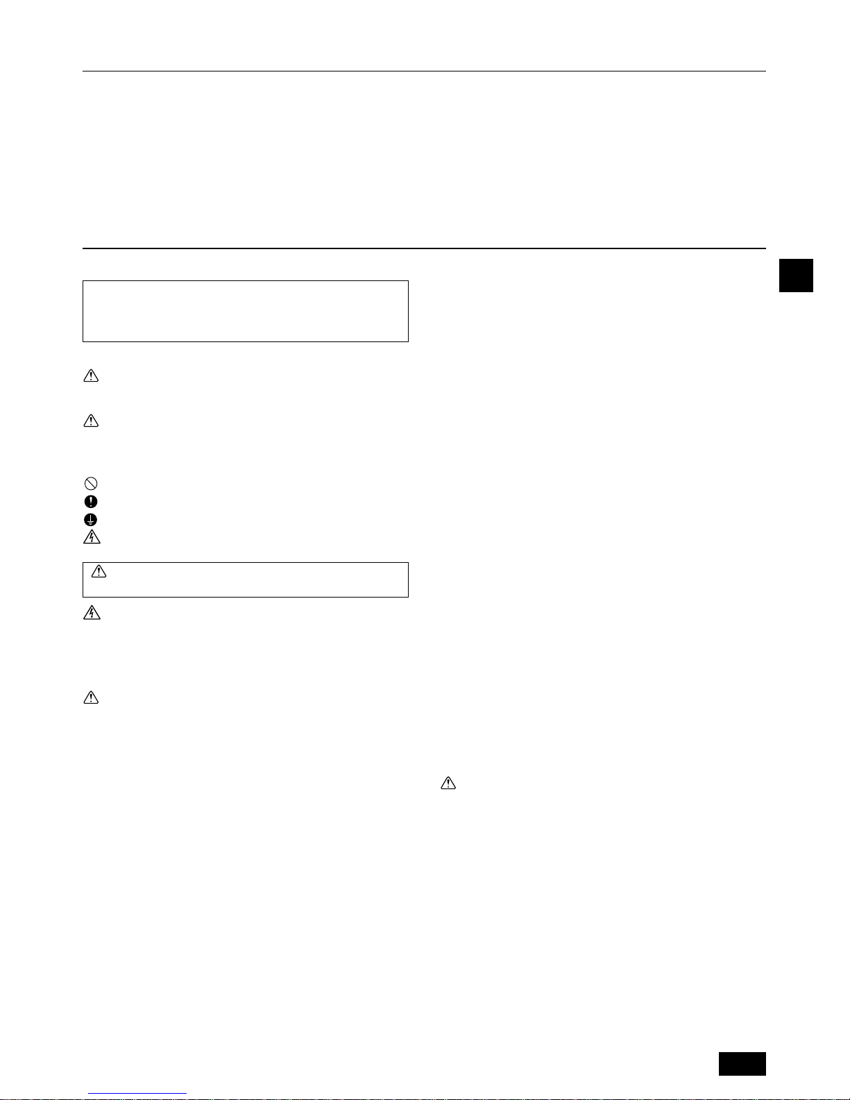
s Connect all wires securely.
• Fix power source wiring to control box by using buffer bushing for tensile force
(PG connection or the like).
[Fig. 5.0.1] (P.6)
A Control box B Power source wiring
C ø21 hole (closed rubber bushing) D Transmission wiring
s Never connect the power cable to the terminal board for control cables.
(Otherwise it may be broken.)
s Be sure to wire between the control wire terminal boards for indoor unit,
outdoor unit and BC controller.
Use non-polarized 2-wire as transmission cables.
Use 2-core shielding cables (CVVS, CPEVS) of more than 1.25 mm
2
in diameter
as transmission cables.
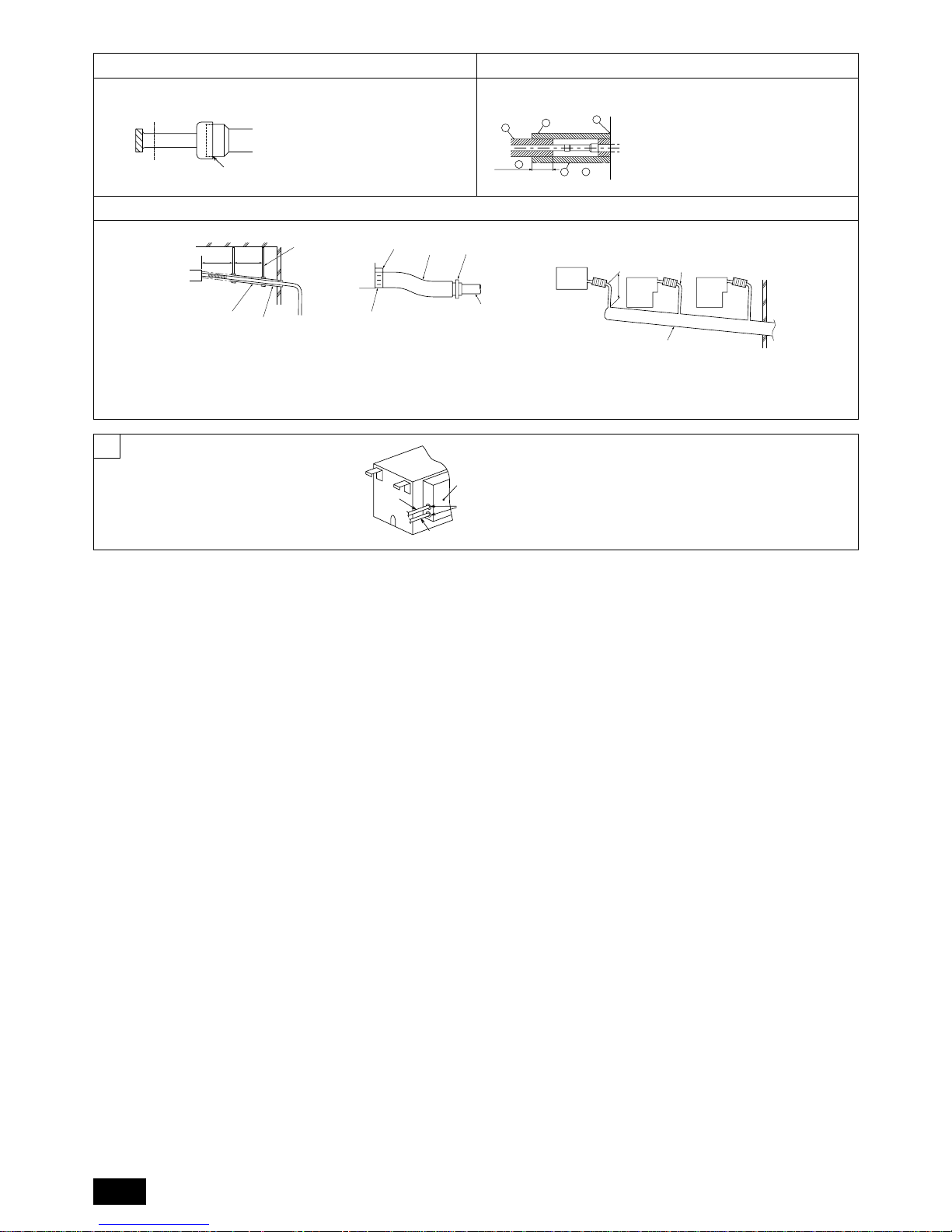
4.3. Insulating refrigerant pipes
Be sure to add insulation work to refrigerant piping by covering high-pressure pipe and
low-pressure pipe separately with enough thickness heat-resistant polyethylene, so
that no gap is observed in the joint between indoor unit and insulating material, and
insulating materials themselves. When insulation work is insufficient, there is a possibility
of condensation drip, etc. Pay special attention to insulation work in the ceiling plenum.
[Fig. 4.3.1] (P.6)
A Locally procured insulating material for pipes
B Bind here using band or tape. C Do not leave any opening.
D Lap margin: more than 40 E Insulating material (field supply)
F Unit side insulating material
• Insulation materials for the pipes to be added on site must meet the following
specifications:
Outdoor unit High-pressure pipe 10 mm or more
-BC controller Low-pressure pipe 20 mm or more
BC controller Pipe size 6.35 mm to 25.4 mm 10 mm or more
-indoor unit Pipe size 28.58 mm to 38.1 mm 15 mm or more
Temperature Resistance 100°C min.
• Installation of pipes in a high-temperature high-humidity environment, such as
the top floor of a building, may require the use of insulation materials thicker
than the ones specified in the chart above.
• When certain specifications presented by the client must be met, ensure that
they also meet the specifications on the chart above.
• The brazed connections must be covered with the insulations, its cutting surface
upward and fastened with the bands.
4.4. Drain piping work
1. Drain piping work
• Ensure that the drain piping is downward (pitch of more than 1/100) to the
outdoor (discharge) side. If it is impossible to take any downward pitch, use an
optionally available drain-up mechanism to obtain a downward pitch of more
than 1/100.
• Ensure that any cross-wise drain piping is less than 20 m. If the drain piping is
long, support it with metal brackets to prevent it from bending, warping, or
vibrating.
Molded case
circuit breaker
Earth leakage
breaker
• Connect the supplied drain hose to the discharge port on the unit body. Use
hard vinyl chloride pipes VP-25 (ø32) for drain piping (2). Tighten the supplied
drain hose onto the discharge port using the supplied hose band. (For this, do
not use any adhesive because the drain hose will need to be removed for
servicing at a later date.)
• Do not use any odor trap around the discharge port.
[Fig. 4.4.1] (P.6)
A: 25 cm B: 1.5 – 2 m
A Downward pitch of more than 1/100
B Insulating material C Supporting bracket
D Drain discharge port E Drain hose (200 mm long, accessory)
F Tie band (accessory) G Hose band (accessory)
•
As shown in 3, install a collecting pipe about 10 cm below the drain ports and give
it a downward pitch of more than 1/100. This collecting pipe should be of VP-30.
• Set the end of drain piping in a place without any risk of odor generation.
•
Do not put the end of drain piping into any drain where ionic gases are generated.
• Drain piping may be installed in any direction. However, please be sure to
observe the above instructions.
• When using an optionally available drain-up mechanism, follow its instruction
manual regarding its installation and use.
[Fig. 4.4.2] (P.6)
A BC controller B Indoor unit
C Collecting pipe D Please ensure this length is at least 10 cm.
2. Discharge test
After completing drain piping work, open the BC controller panel, and test drain
discharge using a small amount of water. Also, check to see that there is no water
leakage from the connections.
3. Insulating drain pipes
Provide sufficient insulation to the drain pipes just as for refrigerant pipes.
Caution:
Be sure to provide drain piping with heat inslation in order to prevent excess
condensation. Without drain piping, water may leak from the unit causing
damage to your property.
The switch capacity of the main power to BC controllers and the wire size are as
follows:
Switch (A)
Wire size
Capacity Fuse
16 16 20 A 20 A 30 mA 1.5 mm
2
0.1 s or less
• For other detailed information, refer to the outdoor unit installation manual.
• Power supply cords of appliances shall not be lighter than design 245 IEC 53
or 227 IEC 53.
• A switch with at least 3 mm contact separation in each pole shall be provided
by the Air conditioner installation.
Caution:
Do not use anything other than the correct capacity fuse and breaker. Using
fuse, conductor or copper wire with too large capacity may cause a risk of
malfunction or fire.
Ensure that the outdoor units are put to the ground. Do not connect the earth
cable to any gas pipe, water pipe, lightening rod or telephone earth cable.
Incomplete grounding may cause a risk of electric shock.
6. Setting addresses and operating units
7. Test run
Before commencing a test run please check the following:
s After installing, piping and wiring the indoor units and BC controllers,
check to see again that there is no refrigerant leakage and no slack on
power and control cables.
s Use a 500 V megger to check that there is an insulation resistance of
more than 1.0 MΩ between the power terminal block and the ground. If it
is less than 1.0 MΩ, do not operate the unit.
5. Electrical work
The address switch of each BC controller is set to “000” when shipped from the
factory.
• Set the address switch to 1 + the address of the outdoor unit.
s The BC controller address should generally be set to 1 + the address of
the outdoor unit. However, if this would result in it having the same address as another outdoor unit, set the address between 51 and 100, making sure that it is different from the address of other controllers.
• Please refer to the outdoor unit installation manual.
Caution:
Never measure the insulation resistance of the terminal block for any control
cables.
Page 13

63
GBDFEINLPGR
RUTRCZSVSLHGPO
Содержание
1. Меры предосторожности
1.1. До установки и монтажа проводки
s Перед установкой системы необходимо внимательно
ознакомиться с разделом “Меры предосторожности”.
s Раздел “Меры предосторожности” содержит важную
информацию по безопасности. Правила безопасности
следует соблюдать в обязательном порядке.
Символы, используемые в тексте
Предупреждение:
Несоблюдение данных предупреждений может привести к
травмированию людей или летальному исходу.
Внимание:
Несоблюдение данных инструкций может привести к выходу
оборудования из строя.
Символы, используемые в иллюстрациях
: Служит для обозначения действий, запрещенных к выполнению.
: Служит для обозначения инструкций, подлежащих выполнению.
: Служит для обозначения узла, который должен быть заземлен.
: Указывает на опасность поражения электрическим током. (Данный
символ отображается на предупреждающей наклейке, закрепленной
на основном блоке.) <Цвет: желтый>
Предупреждение:
Внимательно ознакомьтесь с содержанием
предупреждающих табличек на основном блоке.
ПРЕДУПРЕЖДЕНИЕ О ВЫСОКОМ НАПРЯЖЕНИИ:
• В блоке управления содержатся узлы под высоким напряжением.
• При открывании передней панели следует принять меры к
исключению их контакта с внутренними компонентами.
• Перед тем как приступить к осмотру внутренней части блока
управления, необходимо отключить питание не менее, чем на 10
минут.
Предупреждение:
• Установка кондиционера воздуха должна производиться силами
специалистов дилерского центра либо другим специалистом,
обладающим соответствующей квалификацией.
- Ненадлежащая установка самим пользователем может стать причиной
утечки воды, поражения электрическим током, возгорания и т.д.
• Монтаж должен осуществляться на таком месте, которое является
достаточно прочным, чтобы выдержать вес кондиционера.
- Невыполнение данного условия может привести к падению
кондиционера и травмированию людей.
• Для проводки используйте только специальные кабели. Убедитесь
в надежности подсоединения и в том, что внешние силы,
прикладываемые к кабелю, не передаются на клеммы.
- Ненадлежащим образом выполненные подсоединения и слабая
затяжка могут вызвать нагрев и последующее возгорание.
• Монтаж производится в специально предназначенном месте, с
запасом прочности на случай сильных ветров и землетрясений.
- Нарушение правил монтажа может привести к падению кондиционера
и травмированию людей.
• Aксессуары, указанные компанией Mitsubishi Electric, должны
использоваться в обязательном порядке.
- Для установки аксессуаров необходимо обратиться к помощи
квалифицированного специалиста. Ненадлежащая установка самим
пользователем может стать причиной утечки воды, поражения
электрическим током, возгорания и т.д.
• Запрещается ремонтировать кондиционер самостоятельно. При
необходимости выполнения ремонта следует обратиться в
дилерский центр.
- Ненадлежащим образом выполненный ремонт может стать причиной
утечки воды, поражения электрическим током, возгорания и т.д.
• При возникновении утечки хладагента во время проведения
монтажных работ необходимо проветрить помещение.
- В результате контактирования хладагента с открытым огнем
происходит выделение ядовитых газов.
• Установка кондиционера воздуха должна производиться в полном
соответствии с Руководством по установке.
- Ненадлежащим образом выполненная установка может стать причиной
утечки воды, поражения электрическим током, возгорания и т.д.
• Все работы, связанные с электричеством, должны выполняться
квалифицированным электриком в полном соответствии с
“Электротехническими стандартами” и “Нормами проведения
внутренней проводки” и инструкциями, указанными в Руководстве
по установке. Характеристики электропитания должны строго
соответствовать рекомендованным.
- Несоответствие характеристик подаваемого питания
рекомендованным или нарушение правил установки могут привести с
сбоям в работе кондиционера, поражению электрическим током или
возгоранию.
• Надежно устанавливайте крышку блока управления.
- Если крышка неправильно установлена, в наружный блок может
попасть вода или пыль, в результате чего может возникнуть пожар или
поражение электрическим током.
• При установке или переноске кондиционера воздуха на другое место
для его заправки следует применять только хладагент,
рекомендованный к применению с данным кондиционером.
- Использование иного хладагента, а также проникновение воздуха в
систему приведет к нарушениям его циркуляции и выходу кондиционера
из строя.
• При установке кондиционера воздуха в небольшом помещении
следует предварительно провести измерения и убедиться в том, что
в случае аварийной утечки в этом помещении не будет превышена
предельно допустимая концентрация паров хладагента.
- Для получения информации по размерам помещения обратитесь в
дилерский центр. Превышение концентрации паров хладагента в случае
его аварийной утечки повлечет за собой недопустимое снижение
содержания кислорода в воздухе.
• Перед проведением работ по перемещению или повторной его
установке необходимо проконсультироваться с сотрудниками
дилерского центра или квалифицированным специалистом.
- Ненадлежащим образом выполненная установка может стать причиной
утечки воды, поражения электрическим током, возгорания и т.д.
• После окончания монтажных работ следует убедиться в отсутствии
утечки хладагента.
- Контакт хладагента с нагревательными приборами, кухонной плитой и
иными источниками тепла может привести к выделению токсичных
газов.
• Запрещается вносить любые изменения в конструкцию защитных
устройств и изменять их настройки.
- Короткое замыкание реле давления, теплового реле и иных защитных
устройств, приложение к ним физического воздействие, равно как
применение компонентов, отличных от указанных компанией Mitsubishi
Electric, может привести к возгоранию или взрыву.
• По вопросам, связанным с утилизацией данного изделия следует
обращаться в дилерский центр.
• Мастер монтажа и электрик должны обеспечить защиту системы от
протечек в соответствии с требованиями местного законодательства
и стандартов.
- Выберите провод соответствующего размера и переключатели
необходимой мощности для основного блока питания, описанного в
данном руководстве, при отсутствии местных норм.
1. Меры предосторожности ....................................................................... 63
1.1. До установки и монтажа проводки ...................................... 63
1.2. Меры предосторожности для приборов, в которых
используется хладагент R410A ............................................ 64
1.3. Перед установкой .................................................................. 64
1.4. Перед монтажом (переносом) проводки ............................. 64
1.5. Перед началом тестового запуска ...................................... 64
2. Выберите место установки .................................................................... 65
2.1. Информация о продукте ....................................................... 65
2.2. Место установки .................................................................... 65
2.3. Обеспечение необходимого пространства для установки
и техобслуживания................................................................ 65
2.4. Проверка места установки ................................................... 65
3. Инсталляция Регулятора ВС ................................................................. 67
3.1. Проверка наличия дополнительных принадлежностей,
поставляемых в комплекте с Регулятором ВС .................. 67
3.2. Инсталляция Регуляторов ВС .............................................. 67
4. Подсоединение труб хладагента и дренажных труб ........................... 67
4.1. Подсоединение труб хладагента ......................................... 67
4.2. Прокладка труб хладагента ................................................. 68
4.3. Изоляция труб хладагента ................................................... 69
4.4. Прокладка дренажных труб ................................................. 69
5. Электроработы ....................................................................................... 69
6. Установка адресов и операционных блоков ........................................ 70
7. Выполнение испытания .......................................................................... 70
Page 14

64
GBDFEINLPGR
RUTRCZSVSLHGPO
• Особое внимание необходимо уделять области установки изделия,
и особенно его основанию, где возможно скопление паров
охлаждающего газа, который тяжелее воздуха.
1.2. Меры предосторожности для
приборов, в которых используется
хладагент R410A
Внимание:
• Не используйте имеющиеся трубы хладагента.
- Использование старых труб хладагента и старого масла охлаждения,
содержащих большие количества хлора, может привести к порче масла
охлаждения нового прибора.
- R410A является хладагентом высокого давления, что может привести
к разрыву существующих труб.
• Используйте трубы из раскисленной фосфором меди и бесшовные
трубы, выполненные из латуни. Кроме этого убедитесь, что
внутренняя и внешняя поверхность труб чистая, без частиц серы,
окисей, пыли/ грязи, частиц стружки, масел, влаги или других
загрязнений.
- Загрязнение внутренней поверхности труб хладагента может вызвать
ухудшение качеств компрессорного масла.
• Храните предназначенные для установки трубы в помещении,
герметически закрытыми с обоих концов до припайки. (изменения
и другие соединения храните в пластиковом пакете.)
- Попадание в контур охлаждения пыли, грязи или воды, может привести
к ухудшению эксплуатационных качеств масла и выходу компрессора
из строя.
• Нанесите небольшое количество сложного или простого эфира или
алкилбензола на патрубки и фланцевые соединения. (для
внутренних блоков)
- Масло охлаждения потеряет свои свойства при смешивании с большим
количеством минерального масла.
• Используйте для зарядки системы жидкий хладагент.
- При использовании газообразного хладагента для зарядки системы,
состав хладагента в баллоне изменится, а рабочие показатели прибора
могут ухудшиться.
• Разрешается использовать исключительно хладагент R410A.
- При использовании другого агента (например, R22 в смеси с R410A)
наличие в нем хлора может привести к ухудшению эксплуатационных
качеств холодильного масла.
• Используйте вакуумный насос с обратным клапаном.
- Проникновение масла вакуумного насоса в контур охлаждения может
привести к ухудшению эксплуатационных качеств холодильного масла.
• Запрещается использовать следующие инструменты, применяемые
с обычными видами хладагента.
(Штуцер манометра, заправочный шланг, течеискатель, обратный
клапан, заправочное основание, оборудование для сбора
хладагента)
- Попадание обычного хладагента и холодильного масла в R410A может
привести к ухудшению эксплуатационных свойств хладагента.
- Попадание воды R410A приведет к ухудшению эксплуатационных
свойств холодильного масла.
- Поскольку в состав R410A хлорин не входит, течеискатели,
используемые для работы с обычными хладагентами, не применимы.
• Запрещается использовать заправочные баллоны.
- Использование заправочного баллона может привести к ухудшению
эксплуатационных свойств хладагента.
• Не используйте противоокислительные или обнаруживающие
утечку добавки.
• При работе с инструментом следует принимать меры
предосторожности.
- Попадание в холодильный контур пыли, грязи или воды может привести
к ухудшению эксплуатационных свойств хладагента.
1.3. Перед установкой
Внимание:
• Запрещается устанавливать этот блок в местах, где возможна утечка
огнеопасных газов.
- Утечка газа и его скопление возле кондиционера может привести к
взрыву.
• Не используйте кондиционер в местах хранения продуктов питания,
точных инструментов, произведений искусств, а также местах
нахождения домашних животных и растений.
- Это може вызвать, например, порчу продуктов питания.
• Не используйте кондиционер воздуха в особых условиях
эксплуатации.
- Наличие масел, пара, испарений серы и т.д. может вызвать
значительное ухудшение рабочих показателей кондиционера или выход
его компонентов из строя.
• При установке прибора в больнице, на станции связи или в
аналогичном помещении обеспечьте достаточную защиту от шума.
- Преобразовательное оборудование, частный электрогенератор,
высоковольтное медицинское оборудование или оборудование для
радиосвязи могут вызвать сбой в работе кондиционера или его
отключение. С другой стороны, кондиционер может мешать работе
такого оборудования создаваемым шумом, который нарушает ход
медицинских процедур или радиовещания.
• Не устанавливайте изделие на конструкции, которые могут вызвать
утечку.
- Если влажность в помещении превышает 80 % или засорена дренажная
труба, с внутреннего (комнатного) блока или ВС-контроллера
(устройства для смены режима охлаждение-нагрев) может капать
конденсат. Дренаж внутреннего и наружного блоков выполняется
одновременно, по необходимости.
1.4. Перед монтажом (переносом)
проводки
Внимание:
• Заземлите изделие.
- Не подсоединяйте провод заземления к газовой трубе, водяной трубе,
громоотводу или линии заземления телефонной проводки.
Неправильно выполненное заземление может стать причиной
поражения электрическим током.
• Проложите сетевой кабель так, чтобы он не был натянут.
- Натяжение может привести к разрыву кабеля и стать причиной
перегрева и возгорания.
• Надлежащим образом установите основной автоматический
выключатель.
- Отсутствие выключателя может привести к поражению электрическим
током.
• Используйте провода питания с рекомендованными
характеристиками.
- Кабели слишком малой мощности могут прогореть, вызвать перегрев
и пожар.
• Используйте автоматический выключатель и предохранитель с
рекомендованными характеристиками.
- Использование автоматического выключателя или предохранителя
большего номинального тока, а также применение самодельных
устройств может привести к выходу изделия из строя или возгоранию.
• Запрещается мыть блок кондиционера.
- Невыполнение этого требования может привести к поражению
электрическим током.
• В течение всего срока эксплуатации следует проверять состояние
монтажного основания кондиционера.
- Потеря свойств основания может привести к падению блока с
возможным травмированием людей или порчей имущества.
• Для обеспечения правильного дренирования установка дренажных
трубок должна производиться в полном соответствии с
Руководством по установке. Во избежание конденсации влаги трубы
должны быть изолированы.
- Неправильная установка дренажной системы может привести к утечке
воды и порче мебели или иного личного имущества.
• Будьте очень внимательным при транспортировке изделия.
- Запрещается переносить изделие силами одного человека. Его масса
превышает 20 кг.
- Для упаковки некоторых изделий используются пластиковые ленты.
Не применяйте их для транспортировки. Это опасно.
• Утилизируйте упаковочные материалы с соблюдением правил
безопасности.
- Такие упаковочные материалы, как гвозди и другие металлические или
деревянные предметы, могут причинить порезы и иные травмы.
- Порвите пластиковый упаковочный пакет и утилизируйте так, чтобы
он был недоступен детям. Не позволяйте детям играть с пластиковой
упаковкой, это грозит летальным исходом от удушения.
1.5. Перед началом тестового запуска
Внимание:
• Подключите электропитание не менее чем за 12 часов до начала
работы.
- Запуск сразу после подключения сетевого питания может серьезно
повредить внутренние комоненты изделия. Сетевой выключатель
должен оставаться включенным в течение всего периода эксплуатации
изделия. Строго соблюдайте полярность всех подключений.
• Не прикасайтесь к выключателям мокрыми руками.
- Прикосновение к выключателю мокрыми руками может привести к
поражению электрическим током.
Page 15

65
GBDFEINLPGR
RUTRCZSVSLHGPO
2.3. Обеспечение необходимого
пространства для установки и
техобслуживания
1. При подвешивании на потолке
(На иллюстрации показано пространство, необходимое для установки.)
[Fig. 2.3.1] (P.2)
<A> Вид сверху <B> Вид спереди
A Инспекционное отверстие B Со стороны труб наружного прибора
C Блок управления
D Со стороны труб внутреннего прибора
*1 Необходимые габариты для работы с соединениями труб на
месте установки
2. Выберите место установки
2.1. Информация о продукте
• В данном блоке используется хладагент R410A.
• Трубопроводы для систем, в которых используется хладагент R410A,
могут отличаться от трубопроводов для систем, в которых используется
обычный хладагент, так как расчетное давление в системах с R410A
выше. Для получения дополнительных сведений см. Справочник.
• Некоторые инструменты и оборудование, используемые для установки
систем с другими типами хладагента, не могут использоваться при
установке систем, в которых используется хладагент R410A. Для
получения дополнительных сведений см. Справочник.
• Не используйте существующие трубопроводы, так как в них содержится
хлор, обнаруживаемый в масле и хладагенте обычных холодильных
машин. Хлор ухудшит свойства масла в холодильной машине нового
оборудования. Запрещается использовать существующие трубопроводы,
так как расчетное давление в системах, в которых используется
хладагент R410A, выше, чем в системах, в которых используются другие
типы хладагентов, и возможен разрыв существующих труб.
2.2. Место установки
• Устанавливайте блок в таком месте, где он не попадет под дождь. ВСконтроллер предназначен для установки в помещении.
• При установке блока необходимо учесть свободное пространство для
удобства обслуживания.
• Не устанавливайте блок там, где пришлось бы превысить ограничения
по длине трубопроводов.
• Устанавливайте блок в таком месте, где он не будет подвергаться прямому
воздействию тепла, излучаемого другими источниками.
• Не устанавливайте прибор в месте, где наблюдаются большие объемы
масел или пара, или вблизи оборудования, которое генерирует высокие
частоты. Это может вызвать риск пожара, неправильную работу прибора
или конденсацию.
• Устанавливайте блок в таком месте, чтобы шум при его работе не
создавал проблем для окружающих.
(При установке в помещении с низким уровнем шума, например,
гостиничных номерах, размещайте внутренний блок и ВС-контроллер на
расстоянии не менее 5 м друг от друга).
• Обеспечьте наличие достаточного пространства и доступ к
трубопроводам воды и хладагента, а также к электрическим проводам
для легкого их подсоединения.
• Избегайте установки в местах, подверженных скоплению, притоку,
образованию или утечки возгорающихся и сернистых газов.
• Обеспечьте нисходящий уклон дренажной трубы не менее 1/100.
• Правильно установите блок на устойчивую несущую поверхность.
1. При укреплении на потолке [Fig. 2.2.1] (P.2)
• Предусмотрите смотровое отверстие размером 450 кв. мм на поверхности
потолка, как показано на [Fig. 2.3.1] (P.2).
• Установите блок в подходящем месте (например, на потолке коридора
или в ванной и т.д.) вдали от мест, где регулярно находятся люди.Не
устанавливайте блок в центре комнаты.
• Обеспечьте прочность на выдергивание монтажных болтов не менее 60
кг на болт.
• Устанавливайте регулятор ВС только в горизонтальном положении.
Предупреждение:
Обязательно устанавливайте блок в таком месте, которое способно
выдерживать его полный вес.
При недостаточной прочности места установки прибор может упасть,
что приведет к личной травме.
Внимание:
Устанавливайте блок только в горизонтальном положении.
• Не прикасайтесь к трубам хладагента во время работы и сразу после
выключения прибора.
- В течение и сразу после эксплуатации прибора трубы хладагента могут
быть горячими или холодными, в зависимости от условий протекающего
в трубах, компрессоре и других компонентах холодильного контура. Вы
можете обжечь или обморозить руки при прикосновении к трубам
хладагента.
• Не используйте кондиционер воздуха, если его панели и крышки
сняты.
- Движущиеся, горячие части или части под напряжением могут
причинить травму.
• Не отключайте питание немедленно после выключения прибора.
- Следует выждать не менее пяти минут до отключения питания. Иначе
может возникнуть утечка воды и иные неисправности.
Наименование модели
AB
CMB-P104V-G1
CMB-P105V-G1
CMB-P106V-G1 648
CMB-P108V-G1
CMB-P1010V-G1
CMB-P1013V-G1
1098
CMB-P1016V-G1
CMB-P108V-GA1
CMB-P1010V-GA1
1110 200
CMB-P1013V-GA1
CMB-P1016V-GA1
CMB-P104V-GB1
648
CMB-P108V-GB1
CMB-P1016V-HA1 1110 200
CMB-P1016V-HB1 1098
-
2.4. Проверка места установки
Проверьте, что перепад высоты между местом установки внутреннего и
внешнего приборов, а также длина труб хладагента соответствуют
указанным ниже параметрам.
1. CMB-P104, 105, 106, 108, 1010, 1013, 1016G1 (Если производительность
наружного блока 14 -hp (модель P350) и менее и используется 16 и
менее портов).
[Fig. 2.4.1] (P.2)
A Внешний прибор B Регулятор BC
C Внутренний прибор
D Модель Р100–Р250:2 порта объединены.
E H менее=50 м (если внешнее устройство расположено выше внутреннего
устройства )
F H1 менее=40 м (если внешнее устройство расположено ниже внутреннего
устройства)
G 2-трубная магистраль (для серии Y) CMY-Y102S-G2
H Комбинированная труба (CMY-R160-J1: приобретается дополнительно)
I Менее 110 м J Менее 40 м
K До трех приборов на 1 отверстие ответвления
Общая мощность: менее 80 (одинаковая в режиме охлаждения/отопления)
L h1 менее=15 м (10 м или менее для блоков типа 200, 250)
M h2 менее=15 м
Page 16

66
GBDFEINLPGR
RUTRCZSVSLHGPO
(Единица измерения: м)
ПримечанЉия:
*1 См. “Restrictions on piping length (Ограничения по длине
трубопроводов)” на P. 4.
*2 Обратитесь к рисунку “Расстояние между ВС-контроллером и самым
дальним внутренним блоком”, если расстояние между ВСконтроллером и самым дальним внутренним блоком превышает 40
м. (Не применимо к внутреннему блоку модели P250)
*3 Значения в скобках показывают допустимую предельную длину
трубопровода, если присоединительная способность внутреннего
блока 200 и более.
*4 В системе с внутренними блоками модели P200 и выше нельзя
использовать ответвитель или коллектор.
*5 Не подсоединяйте внутренние блоки моделей P200 или P250 и другие
модели внутренних блоков к одному порту.
*6 В системе с внутренними блоками моделей P100–P140 включительно
объедините перед подсоединением два порта.(Установите
двухпозиционный переключатель SW4-6 на ВС-контроллере в
положение ON (ВКЛ).)
*7 Внутренние блоки моделей P100 по P140 включительно можно
подсоединять к одному порту.(Установите двухпозиционный
переключатель SW4-6 в положение OFF (ВЫКЛ).)Имейте в виду, что
охлаждающая способность несколько снизится.(Двухпозиционный
переключатель SW4-6 устанавливается изготовителем в положение
OFF (ВЫКЛ).)
*8 Внутренние блоки, подсоединенные к одному ответвителю, не могут
одновременно работать в разных рабочих режимах.
15105
20
10
0
0
70
60
50
40
30
Расстояние между регулятором BC и
самым удаленным внутренним прибором.
Расстояние между регулятором BC и самым
удаленным внутренним прибором. (м)
Разница высот между регулятором
BC и самым удаленным внутренним
прибором (м)
2 CMB-P108, 1010, 1013, 1016GA1, P104, 108GB1 (GA1: В случае если
производительность наружного блока 26 -hp (модель P650) и менее).
CMB-P1016HA1, 1016HB1 (HA1: В случае если производительность
наружного блока 28-hp (модель P700) и более).
[Fig. 2.4.2] (P.3)
A Наружный блок B ГЛАВНЫЙ ВС-контроллер
C ВСПОМОГАТЕЛЬНЫЙ ВС-контроллер
D Внутренний блок
E Ветвь трубный комплект подсоединяется внутри наружного блока на
стороне низкого давления.
При подсоединении наружных блоков разной производительности ветвь
трубный комплект подсоединяйте к блоку большей производительности.
F Ветвь трубная магистраль (для серии R2) CMY-R100VBK, CMY-R200VBK
(для серии WR2) CMY-Q100VBK
G Ветвь трубная магистраль (для серии Y) CMY-Y202-G2, CMY-Y102L-G2,
CMY-Y102S-G2
H Ветвь трубная магистраль (CMY-R160-J1: дополнительно)
I Ветвь трубная магистраль (для серии Y) CMY-Y102S-G2
J Модель Р100–Р250:2 порта объединены
K Не более 3 блоков на пару портов
Общая производительность 80 и ниже
Все блоки, подключаемые к одному порту, должны работать в одном
режиме.
L Меньше чем Н = 50 м (когда наружный блок находится выше, чем внутренний)
M Меньше чем Н1=40 м (когда наружный блок находится ниже, чем внутренний)
N Меньше чем h1=15 м (10 м и менее для блоков типоразмера 200, 250)
O Меньше чем h2=15 м
ДлинаРазница по высоте
Часть трубы
A+B+a+b
+c+d+e
A+e
A
e
H
H1
h1
h2
Часть
Общая длина трубы
Самый длинный отрезок трубы
Между внешним прибором и
регулятором ВС
Между внутренним приборами и
регулятором ВС
Над внешним
прибором
Ниже внешнего
прибором
Между внутренним приборами и
регулятором ВС
Между внутренним приборами
Допустимое
значение
Ниже 110
Ниже 40 *2
Ниже 50
Ниже 40
Ниже 15
(Ниже 10)*3
Ниже 15
(Ниже 10)*3
Между
внутренним и
внешним
приборами
Не превышать
максимальной длины
трубопровода хладагента *1
165 м и менее
(эквивалентная
длина 190 м и менее)
Длина
Участок
трубопровода
F+G+A+B+C
+D+E+a+b
+c+d+e+f
F(G)+A+C+E+f
F(G)+A
B+d или C+D+e
или C+E+f
F+G
H
H’
h1
h2
h3
h4
Поз.
Общая длина трубопровода
Максимальная длина
трубопровода
Между наружным блоком и ВСконтроллером
Между внутренними блоками и
ВС-контроллером
Между наружными блоками
Над наружным
блоком
Под наружным
блоком
Между внутренними блоками и
ВС-контроллером
Между внутренними блоками
Между ВС-контроллером (главным
или вспомогательным) и ВСконтроллером (вспомогательным)
Между наружными блоками
Допустимое
значение
Ниже 110
Ниже 40 *2
Ниже 5
Ниже 50
Ниже 40
Ниже 15
(Ниже 10)*3
Ниже 15
(Ниже 10)*3
Ниже 15
Ниже 0,1
Не превышать
максимальной длины
трубопровода хладагента *1
165 м и менее
(эквивалентная
длина 190 м и менее)
(Единица измерения: м)
Перепад высот
Между
внутренними
и наружными
блоками
Примечания:
Для системы с более чем 16 точками ответвления требуется 2–3 ВСконтроллера (главных и вспомогательных) и 3 трубы для соединения
главных и вспомогательных ВС-контроллеров.
*1 См. “Restrictions on piping length (Ограничения по длине
трубопроводов)” на P. 4.
*2 Если расстояние между главным ВС-контроллером и самым
дальним внутренним блоком превышает 40 м, см. рис. “Расстояние
между главным ВС-контроллером и самым дальним внутренним
блоком”. (Не применимо для внутреннего блока модели Р250)
*3 Значения в скобках показывают допустимую предельную длину
трубопровода, если присоединительная способность внутреннего
блока 200 и более.
*4 В системе с внутренними блоками модели P200 и выше нельзя
использовать ответвитель или коллектор.
*5 При подсоединении двух вспомогательных ВС-контроллеров общая
длина трубопроводов не должна превышать максимальную,
указанную слева.
*6 При подсоединении двух вспомогательных ВС-контроллеров
устанавливайте их параллельно.
*7 В системе с внутренними блоками моделей P100–P140 включительно
объедините перед подсоединением два порта.(Установите
двухпозиционный переключатель SW4-6 на ВС-контроллере в
положение ON (ВКЛ).)
*8 Внутренние блоки моделей P100 по P140 включительно можно
подсоединять к одному порту.(Установите двухпозиционный
переключатель SW4-6 в положение OFF (ВЫКЛ).)Имейте в виду, что
охлаждающая способность несколько снизится.(Двухпозиционный
переключатель SW4-6 устанавливается изготовителем в положение
OFF (ВЫКЛ).)
Page 17

67
GBDFEINLPGR
RUTRCZSVSLHGPO
3.1. Проверка наличия дополнительных
принадлежностей, поставляемых в
комплекте с Регулятором ВС
Указанные ниже материалы поставляются с каждым регулятором BC.
3.2. Инсталляция Регуляторов ВС
Установка навесных болов
Установите наложенные по месту навесные болты (резьбовая шпилька) в
соответствии с процедурой, приведенной на иллюстрации. Размер навесного
болта: ø10 (винт М10)
Для того чтобы навесить прибор, используйте подъемное оборудование и
продвиньте прибор через навесные болты.
Кронштейн подвески имеет овальное отверстие.Используйте устройство для
промывки с большим диаметром.
[Fig. 3.2.1] (P.4)
1 Метод навешивания
A: Минималь 30 мм
A Навесной болт ø10 (Приобретается на месте.)
B Прокладка (Приоретается на месте.)
s Обязательно проверьте, что регулятор BC установлен
горизонтально, с помощью уровня. Если регулятор установлен под
углом, возможна утечка конденсата. Если регулятор установлен под
уклоном, ослабьте крепежные гайки на подвесном кронштейне и
отрегулируйте положение регулятора.
Внимание:
Устанавливайте блок только в горизонтальном положении.
3. Инсталляция Регулятора ВС
1
Дренажный шланг
2 Стяжной хомут
3 Хомут шланга
4 Штуцер
хладагента
Поз.
Количество
CMBP104V-G1
P105V-G1
P106V-G1
P108V-G1
P1010V-G1
P1013V-G1
P1016V-G1
1
1
1
Название модели
CMBP108V-GA1
P1010V-GA1
P1013V-GA1
P1016V-GA1
1
1
1
CMBP104V-GB1
P108V-GB1
1
1
1
CMBP1016V-HA1
1
1
1
CMBP1016V-HB1
1
1
1
Расстояние между главным ВС-контроллером
и самым дальним внутренним блоком
Расстояние между главным ВС-контроллером
и самым дальним внутренним блоком (м)
Перепад высот между главным
ВС-контроллером и самым
дальним внутренним блоком (м)
15105
20
10
0
0
70
60
50
40
30
*9 Если производительность наружного блока 28-hp (модель Р700) и
более, используйте главный ВС-контроллер типа НА. ВС-контроллер
типа G нельзя подсоединять к блокам производительностью от
16 -hp (модель P400) до 26-hp (модель P650), а ВС-контроллеры типа
G и GA нельзя подсоединять к блокам производительностью 28 -hp
(модели P650) и более.
*10 Для вспомогательного ВС-контроллера типа GB общая
производительность подсоединяемых внутренних блоков может
быть равной или меньше производительности блока P350. Однако
при использовании двух вспомогательных контроллеров TOTAL
(ОБЩАЯ) производительность блоков, которые могут быть
подсоединены к BOTH (ОБОИМ) вспомогательным контроллерам,
также не должна превышать производительности блока P350.
Для вспомогательного ВС-контроллера типа HB общая
производительность внутренних блоков, которые могут быть
подсоединены, может быть равной или меньше производительности
блока P350.Однако при использовании двух вспомогательных
контроллеров TOTAL (ОБЩАЯ) производительность блоков, которые
могут быть подсоединены к BOTH (ОБОИМ) вспомогательным
контроллерам, также не должна превышать производительности
блока P450.
*11 Внутренние блоки, подсоединенные к одному ответвителю, не могут
одновременно работать в разных рабочих режимах.
*12 Не подключайте внутренние блоки моделей P200 или P250 и другие
модели внутренних блоков к одному порту.
[Fig. 2.4.3] (P.4)
A Общая длина трубопровода (м)
B Длина трубопровода между блоком управления и ВС-контроллером (м)
4. Подсоединение труб хладагента и дренажных труб
4.1. Подсоединение труб хладагента
1. Подсоедините жидкостные и газовые трубы каждого внутреннего блока
к концевым соединениям с теми же (соответствующими) номерами,
которые указаны на секции концевого соединения внутреннего блока
каждого регулятора BC. При подсоединениях к несоответствующим
номерам раструбов прибор не сможет нормально функционировать.
2. Запишите названия моделей внутренних устройств на именной табличке
регулирующей коробки регулятора ВС (с целью идентификации), а
номера соединений, номер регулятора ВС и адресные номера - на именной
табличке внутреннего устройства, расположенной на его боковой панели.
3. Если количество ответвлений превышает количество подсоединяемых
внутренних блоков, допускается использовать любые ответвления.
Закройте неиспользуемые концевые соединения заглушками так, как они
были закрыты при отправке с завода. Если не установить заглушку на
место, произойдет утечка хладагента.
4. При использовании магистрали CMY-Y102S-G2, CMY-Y102L-G2 или CMYY202-G2 подсоединяйте ее только горизонтально.
5. Развальцуйте трубу ответвления внутреннего блока, предварительно
обрезав трубу в соответствующей точке в зависимости от
производительности внутреннего блока.
Примечание:
После обрезания трубы удалите заусенцы во избежание попадания
стружки в трубы.
Убедитесь в отсутствии трещин на развальцованной части трубы.
[Fig. 4.1.1] (P.5)
A Ответвление внутреннего блока
B Точка отреза:
ø
9,52 (сторона жидкости) или ø15,88 (сторона газа)
(Модель внутреннего блока: выше P50)
C Точка отреза:
ø
6,35 (сторона жидкости) или ø12,7 (сторона газа)
(Модель внутреннего блока: P50 или ниже)
D Обрежьте трубу в точке отреза
E Развальцуйте трубу ответвления внутреннего блока
F Монтажная труба
6. Обязательно используйте неокисляемую смазку, где это необходимо.
Если вы не будете использовать неокисляемую смазку, то может
произойти засорение труб.
Сначала припаяйте ответвление внутреннего блока, а затем ответвление
наружного блока регулятора BC, подавая к месту пайки азот.
При пайке ответвления внутреннего блока подавайте азот в отверстие
ответвления наружного блока регулятора BC.
При пайке ответвления наружного блока регулятора BC подавайте азот
в трубу между наружным блоком и регулятором BC.
7. После завершения подсоединения труб, обеспечьте поддержку труб, так
чтобы нагрузка не передавалась на концевые соединения регулятора
BC (особенно на газовые трубы внутренних приборов).
Предупреждение:
При установке и монтаже прибора заряжайте его только хладагентом,
указанным на приборе (R410A).
- Подмешивание другого хладагента, воздуха и т.д. может нарушить цикл
охлаждения и стать причиной серъезного повреждения.
33818
Page 18

68
GBDFEINLPGR
RUTRCZSVSLHGPO
Внимание:
• Для трубопроводов хладагента используйте бесшовные трубы и
трубки из раскисленной фосфором меди и медного сплава.Кроме
этого убедитесь, что внутренняя и внешняя поверхность труб чистая,
без частиц серы, окисей, пыли/грязи, частиц стружки, масел, влаги
или других загрязнений.
- R410A является хладагентом высокого давления и может вызвать
разрыв имеющегося трубопровода.
• Храните предназначенные для установки трубы в помещении,
герметически закрытыми с обоих концов до припайки. (Уголки и
другие соединения храните в пластиковом пакете).
1. Размеры конечных трубных соединений регулятора ВС
[Fig. 4.1.2] (P.5)
Общая мощность внутренних приборов Труба жидкости Труба газа
Ниже 140 ø15,88
от 141 до 200 ø9,52 ø19,05
от 201 до 250 ø22,2
Примечание:
Обязательно используйте неокисляемый припой.
4.2. Прокладка труб хладагента
После соединения труб хладагента всех внутренних и наружных приборов,
при этом клапаны останова наружных приборов должны быть полностью
закрыты, удалите вакуум из сервисных портов клапана останова наружных
приборов.
После завершения описанной выше процедуры откройте клапаны останова
внешних приборов. На этом полностью завершается соединение цепи
хладагента (между внешним прибором и регулятором BC).
Указания о том, как обращаться с клапанами останова, обозначены на
каждом внешнем приборе.
Примечания:
• После соединения труб обязательно проверьте, что нет утечки газа,
пользуйтесь при этом детектором утечки или мыльным раствором.
• Перед пайкой труб хладагента всегда оборачивайте трубы на приборе и
трубы термоизоляции влажными тряпками для предотвращения
усадочной деформации и сгорания труб термоизоляции. Следите за
тем, чтобы пламя не касалось самого корпуса прибора.
• Не используйте добавки для обнаружения утечки.
Предупреждение:
Не подмешивайте в циклах хладагента ничего, кроме указанного агента
(R410A) при установке или перемещении. Подмешивание воздуха может
привести к ненормальному повышению температуры в контуре
охлаждения и вызвать разрыв трубы.
Внимание:
Обрежьте конец трубы наружного блока, удалите газ, а затем удалите
припаянный колпачок.
[Fig. 4.2.1] (P.6)
A Обрезать здесь B Удалить припаянный колпачок
- Попадание в контур циркуляции хладагента пыли, грязи или воды может
привести к ухудшению свойств масла и отказу компрессора.
• Слегка смажьте развальцовки сложноэфирным синтетическим
маслом, эфирным синтетическим маслом или алкилбензолом.(для
внутреннего блока)
- Попадание большого количества минерального смазочного масла может
вызвать ухудшение свойств масла для компрессора.
• Не сбрасывайте хладагент R410A в атмосферу.
• Хладагент R410A является фторсодержащим парниковым газом, на
который распространяется действие Киотского Протокола, с
потенциалом глобального потепления (ПГП) = 1975.
*1 Используйте прилагаемую трубу.
Сторона наружного блока
PURY-(E) P400
PQRY-P400
PURY-(E) P450
PQRY-P450
PURY-(E) P500
PQRY-P500
PURY-(E) P550
PQRY-P550
PURY-(E) P600
PQRY-P600
PURY-P650
PURY-P700
PURY-P750
PURY-P800
Модель блока
PURY-(E) P200
PQRY-P200
PURY-(E) P250
PQRY-P250
PURY-(E) P300
PQRY-P300
PURY-P350
Сторона внутреннего блока
(ВС-КОНТРОЛЛЕР)
CMB-P104V-G1
CMB-P105V-G1
CMB-P106V-G1
CMB-P108V-G1
CMB-P1010V-G1
CMB-P1013V-G1
CMB-P1016V-G1
(ГЛАВНЫЙ ВСКОНТРОЛЛЕР)
CMB-P108V-GA1
CMB-P1010V-GA1
CMB-P1013V-GA1
CMB-P1016V-GA1
(ГЛАВНЫЙ ВСКОНТРОЛЛЕР)
CMB-P1016V-HA1
CMB-P104V-GB1
CMB-P108V-GB1
CMB-P1016V-HB1
ø15,88*1
(Пайка)
ø19,05
(Пайка)
ø19,05*1
(Пайка)
ø22,2
(Пайка)
ø28,58*1
(Пайка)
ø28,58
(Пайка)
ø9,52 или ø6,35
(
Пайка
)
ø19,05*1
(Пайка)
ø22,2
(Пайка)
ø28,58*1
(Пайка)
ø28,58
(Пайка)
ø34,93*1
(Пайка)
ø15,88 или ø12,7
(
Пайка
)
ниже 200
ø15,88*1
(Пайка)
ø19,05*1
(Пайка)
ø9,52
(Пайка)
201~300
ø19,05
(Пайка)
ø22,2
(Пайка)
301~350
351~400
ø22,2*1
(Пайка)
ø28,58*1
(Пайка)
401~450
ø9,52 или ø6,35
(
Пайка
)
ø15,88 или ø12,7
(
Пайка
)
ø12,7*1
(Пайка)
ø15,88*1
(Пайка)
ВС-КОНТРОЛЛЕР /ГЛАВНЫЙ ВС-КОНТРОЛЛЕР
ВСПОМОГАТЕЛЬНЫЙ ВС-КОНТРОЛЛЕР
Название
модели
Сторона высокого
давления
Сторона низкого
давления
Название
модели
Общая производительность
внутренних блоков
Сторона высокого
давления (газа)
Сторона низкого
давления (газа)
Сторона
жидкости
Если в системе имеется более 16 точек разветвления, для соединения труб
используйте ВС-контроллеры (главный и вспомогательный).
A К внешнему прибору (ГЛАВНЫЙ ВС-КОНТРОЛЛЕР)
B Концевое соединение (Пайка)
C Регулятор BC (ГЛАВНЫЙ ВС-КОНТРОЛЛЕР / ВСПОМОГАТЕЛЬНЫЙ ВС-
КОНТРОЛЛЕР)
D Переходник
E Внутренний прибор F Менее 50
G Набор соединения труб (название модели: CMY-R160-J1)
H 2-трубная магистраль (наименование модели: CMY-Y102S-G2)
I До трех приборов на одно отверстие крепления; общая мощность: ниже 80
(одинаковое в режиме охлаждения/отопления)
Размер трубопровода ответвления регулятора BC находится в пределах от
63 до 140 типовых внутренних приборов.
Поэтому, если захотите подсоединить другие внутренние блоки, отличные
от указанных выше, подсоединяйте трубопроводы, как описано ниже.
*1. Для подсоединения внутренних приборов типа 15 до 50
Развальцуйте трубу ответвления внутреннего блока, предварительно
обрезав трубу в соответствующей точке в зависимости от
производительности внутреннего блока.
Примечание:
После обрезания трубы удалите заусенцы во избежание попадания
стружки в трубы.
Убедитесь в отсутствии трещин на развальцованной части трубы.
*2. Для соединения прибора с общей мощностью выше чем 81.
После комбинирования двух ответвлений с помощью приобретенного
отдельно набора трубопроводов (CMY-R160-J1), соедините внутренние
приборы.
*3. Соединение нескольких внутренних приборов одним соединением
(или общей трубой)
• Общая мощность соединяемых внутренних приборов: менее 80 (менее
250 с общей трубой)
• Число соединяемых внутренних приборов: не более 3
• 2-трубная магистраль:Для серии CITY MULTI Y (CMY-Y102S-G2)
используйте 2-трубную магистраль
• Выбор труб хладагента
Выбирайте размер в соответствии с общей мощностью внутренних
приборов, устанавливаемых вниз по потоку.
Page 19

69
GBDFEINLPGR
RUTRCZSVSLHGPO
Ёмкость переключателя питания к регуляторам ВС и сечение провода
приводятся в следующей таблице:
• За дополнительной информацией обращайтесь к руководству по
установке внешнего прибора.
• Шнуры питания устройств не должны быть легче шнуров дизайна 245
IEC 53 или 227 IEC 53.
• Установка кондиционера воздуха предусматривает использование
переключателя с разделением контактов на каждом полюсе не менее
3 мм.
Внимание:
Не используйте предохранитель и прерыватель неверной мощности.
Использование предохранителя, проводника или медного провода
слишком большой мощности может вызвать сбой в работе прибора или
пожар.
Убедитесь в том, что все внешние приборы заземлены. Не
подсоединяйте кабели заземления к кабелям заземления газовой
трубы, трубы для воды, громоотвода или телефонной линии.
Недостаточное заземление может привести к электрошоку.
4.3. Изоляция труб хладагента
В обязательном порядке снабдите трубы хладагента изоляцией (раздельно
трубы высокого и низкого давления) с достаточным количеством
термостойкого полиэтилена таким образом, чтобы отсутствовали зазоры
между внутренним блоком и изоляцией, а также между самими
изоляционными материалами. Недостаточная изоляция может привести к
капанию конденсата. Особое внимание уделите изоляции потолочной
области.
[Fig. 4.3.1] (P.6)
A Изолирующий материал для труб, приобретаемый на месте
B Обмотка с помощью ленты или тесьмы.
C Не оставляйте отверстий. D Перехлестка свыше 40
E Изолирующий материал (приобретается на месте)
F Изолирующий материал боковой стороны прибора
• Изоляционные материалы, приобретаемые на месте, должны отвечать
следующим требованиям:
Наружный блок
Трубка высокого давления
10 мм и более
-Блок управления ВС
Трубка низкого давления
20 мм и более
Блок управления ВС
Диаметр трубы от 6,35 до 25,4 мм
10 мм и более
-внутренний блок
Диаметр трубы от 28,58 до 38,1 мм
15 мм и более
Термостойкость не менее 100 °C
• Установка труб в местах, подверженных воздействию высоких
температур и влажности, например, на верхних этажах зданий, может
потребовать применения материалов большей толщины, чем указано
выше.
• Если клиент выдвигает особые требования, убедитесь в том, что они
отвечают требованиям, перечисленным выше.
• Паяные соединения должны покрываться изоляцией, которая наносится
отрезанной поверхностью наружу и крепится стяжными хомутами.
4.4. Прокладка дренажных труб
1. Прокладка дренажных труб
• Убедитесь, что трубы прокладываются с наклоном вниз (наклон свыше
1/100) к внешней стороне (слив). Если невозможно обеспечить наклон,
используйте приобретенный дополнительно дренажный механиз для
получения наклона вниз свыше 1/100.
• Обеспечьте перекрестные дренажные трубы менее 20 м. Протяженный
дренажный трубопровод прокладывайте на металлических кронштейнах
для предотвращения перегибов, деформации и вибрации.
• Подсоедините поставленный дренажный шланг к сливному порту на
корпусе прибора. Используйте из твердого винилхлорида VP-25 (ø32) для
дренажных труб. (2). Закрепите поставленный дренажный шланг на
порту слива, используя поставленную шланговую ленту. (Не используйте
для монтажа клей, так как дренажный шланг позднее необходимо будет
снять для обслуживания).
• Не ставьте никакой ловушки запахов вокруг выпускного отверстия.
[Fig. 4.4.1] (P.6)
A: 25 см
B: 1,5 – 2 м
A Наклон вниз свыше 1/100 B Изолирующий материал
C Поддерживающая скоба D Порт слива дренажа
E Дренажный шланг (200 мм длиной, поставлена)
F Закрепляющая лента (поставлена)
G Шланговая лента (поставлена)
• Как показано на диаграмме 3, установите трубу сбора примерно на 10 см
ниже выходов дренажа под углом наклона вниз не менее 1/100. Данная
труба сбора должна быть выполнена из VP-30.
• Установите конец дренажной трубы там, где не скапливаются запахи.
• Не помещайте конец дренажной трубы в какой-либо сток, где происходит
генерация ионных газов.
• Дренажный трубопровод можно отводить в любом направлении.Тем не
менее соблюдайте указанные выше инструкции.
• При использовании дополнительного механизма подъема дренажа
(дренажной помпы) соблюдайте инструкции по его монтажу и
использованию.
[Fig. 4.4.2] (P.6)
A Регулятор BC B Внутренний прибор
C Коллекторная труба
D Убедитесь, что эта длина не менее 10 см.
2. Испытание слива
После завершения прокладки дренажного трубопровода откройте панель
ВС-контроллера и небольшим количеством воды проверьте работу
дренажа.Проверьте, нет ли течи в местах соединения.
3. Изоляция дренажных труб
Для дренажных труб необходима такая же изоляция, как для труб хладагента.
Внимание:
Для предотвращения чрезмерной конденсации теплоизолируйте
дренажную трубу.Без дренажного трубопровода может произойти
утечка воды из блока, нанеся ущерб вашей собственности.
s Предварительно проконсультируйтесь о существующих местных
правилах с местными предприятиями.
Предупреждение:
Электромонтажные работы должны выполнять квалифицированные
электрики в соответствии с действующими нормами и инструкциями в
прилагаемых руководствах. Следует использовать специальные линии
электропитания. При недостаточной мощности электропитания или
неудовлетворительной электропроводке возникает риск электрошока
или пожара.
s Все провода присоединяйте надежно.
• Прикрепите проводку источника питания к блоку управления, применив
буферную втулку для придания прочности на растяжение (соединение
PG или подобное).
[Fig. 5.0.1] (P.6)
A Блок управления B Проводка источника питания
C Отверстие ø21 (проходной изолятор закрытого типа из резины)
D Проводка трансмиссии
s Ни в коем случае не подсоединяйте кабель питания к коммутатору
терминалов кабелей регулировки. (В противном случае он может
быть выведен из строя.)
s Не забудьте провести проводку между коммутаторами проводов
регулировки внутреннего устройства, внешнего устройства и
регулятора ВС.
В качестве соединительных кабелей используйте неполяризованные 2проводные
В качестве соединительных кабелей используйте 2-жильные
экранированные (с полиэтиленовой изоляцией, в поливинилхлоридной
оплетке: CVVS (управления), CPEVS (связи)) с сечением проводников более
1,25 мм
2
.
Прерыватель
в цельном
корпусе
20 A
Прерыватель
цепи
заземления
20 A 30 мA
0,1 сек. или
менее
Размер
провода
1,5 мм
2
Предохранитель
16
Мощность
16
Переключатель (А)
5. Электроработы
Page 20

70
GBDFEINLPGR
RUTRCZSVSLHGPO
6. Установка адресов и операционных блоков
Адресный переключатель на каждом регуляторе ВС, поставляемом с заводаизготовителя, установлен на отметку “000”.
• Установите адресный переключатель в положение 1+ адрес внешнего
устройства.
s Адрес регулятора ВС, как правило, должен задаваться по формуле
1+ адрес внешнего устройства. Тем не менее, если при использовании
данной формулы произойдет совпадение адреса регулятора ВС с
адресом другого внешнего устройства, задайте другой адрес в
пределах от 51 до 100. При этом убедитесь, что данный адрес
отличается от адресов других регуляторов.
• См. Руководство по установке внешнего прибора.
7. Выполнение испытания
Перед пробным пуском проверьте следующее:
s После монтажа, подсоединения трубопроводов и электропроводки
к внутреннему блоку и ВС-контроллеру убедитесь в отсутствии течи
хладагента и провисания силовых кабелей и кабелей управления.
s Используя мегомметр на 500 В, проверьте, чтобы сопротивление
изоляции между клеммой питания и землей было не менее 1,0 M1.Не
эксплуатируйте блок, если сопротивление менее 1,0 M1.
Внимание:
Не измеряйте сопротивление изоляции клеммной колодки для какихлибо кабелей управления.
Page 21

WT05845X01
Please be sure to put the contact address/telephone number on
this manual before handing it to the customer.
The product at hand is
based on the following
EU regulations:
• Low Voltage Directive 2006/95/EC
• Electromagnetic Compatibility Directive
2004/108/EC
This product is designed and intended for use in the residential,
commercial and light-industrial environment.
HEAD OFFICE: TOKYO BLDG., 2-7-3, MARUNOUCHI, CHIYODA-KU, TOKYO 100-8310, JAPAN
Printed in Japan
 Loading...