

Mitsubishi CMB-P-NU-G1, CMB-P-NU-HA1, CMB-P-NU-GA1, CMB-P-NU-GB1, CMB-P-NU-HB1 Installation Manual
Page 1

Air-Conditioners For Building Application
INDOOR UNIT
CMB-P-NU-G1
CMB-P-NU-GA1 (MAIN BC CONTROLLER)
CMB-P-NU-GB1 (SUB BC CONTROLLER)
CMB-P-NU-HA1 (MAIN BC CONTROLLER)
CMB-P-NU-HB1 (SUB BC CONTROLLER)
INSTALLATION MANUAL
For safe and correct use, please read this installation manual thoroughly before installing the air-conditioner unit.
MANUEL D’INSTALLATION
Veuillez lire le manuel d’installation en entier avant d’installer ce climatiseur pour éviter tout accident et vous assurer d’une utilisation correcte.
GBF
Page 2
Contents
1. Safety precautions ........................................................................................2
1.1. Before installation and electric work ............................................ 2
1.2. Precautions for devices that use R410A refrigerant .................... 2
1.3. Before installation ........................................................................ 3
1.4. Before installation (relocation) - electrical work ........................... 3
1.5. Before starting the test run .......................................................... 3
2. Items to be used ........................................................................................... 3
2.1. Package contents ........................................................................ 3
2.2. Commercially available items ...................................................... 3
3. Selecting an installation site ......................................................................... 4
3.1. About the product ........................................................................ 4
3.2. Installation site ............................................................................ 4
3.3. Securing installation and service space ...................................... 4
3.4. Checking the installation site ....................................................... 5
1. Safety precautions
1.1. Before installation and electric work
Before installing the unit, make sure you read all the “Safety
u
precautions”.
The “Safety precautions” provide very important points
u
regarding safety. Make sure you follow them.
GB
Symbols used in the text
Warning:
Describes precautions that should be observed to prevent danger of injury
or death to the user.
Caution:
Describes precautions that should be observed to prevent damage to the unit.
Symbols used in the illustrations
:
Indicates an action that must be avoided.
:
Indicates that important instructions must be followed.
:
Indicates a part which must be grounded.
:
Beware of electric shock. (This symbol is displayed on the main unit label.) <Color: Yellow>
Warning:
Carefully read the labels afxed to the main unit.
HIGH VOLTAGE WARNING:
• Control box houses high-voltage parts.
• When opening or closing the front panel of the control box, do not let it
come into contact with any of the internal components.
• Before inspecting the inside of the control box, turn off the power, keep
the unit off for at least 10 minutes.
Warning:
• Ask the dealer or an authorized technician to install the air conditioner.
- Improper installation by the user may result in water leakage, electric
shock, or re.
• Install the unit at a place that can withstand its weight.
- Failure to do so may cause the unit to fall down, resulting in injuries and
damage to the unit.
• Use the specied cables for wiring. Make the connections securely so
that the outside force of the cable is not applied to the terminals.
- Inadequate connection and fastening may generate heat and cause a re.
• Prepare for earthquakes and install the unit at the specied place.
- Improper installation may cause the unit to fall down and result in injury
and damage to the unit.
• Always use accessories specied by Mitsubishi Electric.
- Ask an authorized technician to install the accessories. Improper installa-
tion by the user may result in water leakage, electric shock, or re.
• Never attempt to repair the unit without the proper qualications. If the
air conditioner must be repaired, consult the dealer, contractor or quali-
ed Refrigeration Engineer.
- If the unit is repaired improperly, water leakage, electric shock, or re may
result.
• If refrigerant gas leaks during installation work, ventilate the room.
- If the refrigerant gas comes into contact with a ame, poisonous gases will
be released.
• Install the air conditioner according to this Installation Manual.
- If the unit is installed improperly, water leakage, electric shock, or re may
result.
4. Installing BC controller .................................................................................8
4.1. Installing BC controllers .............................................................. 8
5. Connecting refrigerant pipes and drain pipes...............................................8
5.1. Pipe connecting method .............................................................. 8
5.2. Connecting refrigerant pipes ....................................................... 9
5.3. Refrigerant piping work ............................................................. 10
5.4. Insulating refrigerant pipes ........................................................ 11
5.5. Drain piping work ...................................................................... 11
6. Electrical work ............................................................................................ 11
7. Setting addresses and operating units ....................................................... 12
8. Checklist after installation ...........................................................................12
9. Test run ....................................................................................................... 12
10. Important information to be passed on to the end users ............................ 12
• Have all electric work done by a licensed electrician according to “Electric Facility Engineering Standard” and “Interior Wire Regulations”and
the instructions given in this manual and always use a dedicated power
supply.
- If the power source capacity is inadequate or electric work is performed
improperly, electric shock and re may result.
• Securely install the cover of control box.
- If the cover is not installed properly, dust or water may enter the outdoor
unit and re or electric shock may result.
• When installing and moving the air conditioner to another site, do not
charge it with a refrigerant different from the refrigerant specied on
the unit.
- If a different refrigerant or air is mixed with the original refrigerant, the re-
frigerant cycle may malfunction and the unit may be damaged.
• If the air conditioner is installed in a small room, measures must be taken to prevent the refrigerant concentration from exceeding the safety
limit if the refrigerant should leak.
- Consult the dealer regarding the appropriate measures to prevent the
safety limit from being exceeded. Should the refrigerant leak and cause
the safety limit to be exceeded, hazards due to lack of oxygen in the room
could result.
• When moving and reinstalling the air conditioner, consult the dealer or
an authorized technician.
- If the air conditioner is installed improperly, water leakage, electric shock,
or re may result.
• After completing installation work, make sure that refrigerant gas is not
leaking.
- If the refrigerant gas leaks and is exposed to a fan heater, stove, oven, or
other heat source, it may generate noxious gases.
• Do not reconstruct or change the settings of the protection devices.
- If the pressure switch, thermal switch, or other protection device is shorted
or operated forcibly, or parts other than those specied by Mitsubishi Electric are used, re or explosion may result.
• To dispose of this product, consult your dealer.
• The installer and system specialist shall secure safety against leakage
according to local regulation or standards.
- Choose the appropriate wire size and the switch capacities for the main
power supply described in this manual if local regulations are not available.
• Pay special attention to the place of installation, such as basement, etc.
where refrigeration gas can accumulate, since refrigerant is heavier
than the air.
1.2. Precautions for devices that use
R410A refrigerant
Caution:
• Do not use existing refrigerant piping.
- The old refrigerant and refrigerant oil in the existing piping contains a large
amount of chlorine which may cause the refrigerant oil of the new unit to
deteriorate.
- R410A is a high-pressure refrigerant and can cause the existing piping to
burst.
• Use refrigerant piping made of phosphorus deoxidized copper and
copper alloy seamless pipes and tubes. In addition, be sure that the
inner and outer surfaces of the pipes are clean and free of hazardous
sulphur, oxides, dust/dirt, shaving particles, oils, moisture, or any other
contaminant.
- Contaminants on the inside of the refrigerant piping may cause the refrig-
erant residual oil to deteriorate.
2
Page 3
• Store the piping to be used during installation indoors and keep both
ends of the piping sealed until just before brazing. (Store elbows and
other joints in a plastic bag.)
- If dust, dirt, or water enters the refrigerant cycle, deterioration of the oil and
compressor failure may result.
• Apply a small amount of ester oil, ether oil, or alkyl benzene to ares. (for
indoor unit)
- Inltration of a large amount of mineral oil may cause the refrigerant oil to
deteriorate.
• Use liquid refrigerant to ll the system.
- If gas refrigerant is used to ll the system, the composition of the refriger-
ant in the cylinder will change and performance may drop.
• Do not use a refrigerant other than R410A.
- If another refrigerant (R22, etc.) is mixed with R410A, the chlorine in the
refrigerant may cause the refrigerant oil to deteriorate.
• Use a vacuum pump with a reverse ow check valve.
- The vacuum pump oil may ow back into the refrigerant cycle and cause
the refrigerant oil to deteriorate.
• Do not use the following tools that are used with conventional refrigerants.
(Gauge manifold, charge hose, gas leak detector, reverse ow check
valve, refrigerant charge base, refrigerant recovery equipment)
- If the conventional refrigerant and refrigerant oil are mixed in the R410A,
the refrigerant may deteriorate.
- If water is mixed in the R410A, the refrigerant oil may deteriorate.
- Since R410A does not contain any chlorine, gas leak detectors for conven-
tional refrigerants will not react to it.
• Do not use a charging cylinder.
- Using a charging cylinder may cause the refrigerant to deteriorate.
• Do not use antioxidant or leak-detection additive.
• Be especially careful when managing the tools.
- If dust, dirt, or water gets into the refrigerant cycle, the refrigerant may de-
teriorate.
1.3. Before installation
Caution:
• Do not install the unit where combustible gas may leak.
- If the gas leaks and accumulates around the unit, an explosion may result.
• Do not use the air conditioner where food, pets, plants, precision instruments, or artwork are kept.
- The quality of the food, etc. may deteriorate.
• Do not use the air conditioner in special environments.
- Oil, steam, sulfuric smoke, etc. can signicantly reduce the performance of
the air conditioner or damage its parts.
• When installing the unit in a hospital, communication station, or similar
place, provide sufcient protection against noise.
- Inverter equipment, private power generator, high-frequency medical
equipment, or radio communication equipment may cause the air conditioner to operate erroneously, or fail to operate. On the other hand, the
air conditioner may affect such equipment by creating noise that disturbs
medical treatment or image broadcasting.
• Do not install the unit on or over things that are subject to water damage.
- When the room humidity exceeds 80 % or when the drain pipe is clogged,
condensation may drip from the indoor unit or BC controller. Perform collective drainage work together with the outdoor unit, as required.
1.4. Before installation (relocation) - electrical work
Caution:
• Ground the unit.
- Do not connect the ground wire to gas or water pipes, lightning rods, or
telephone ground lines. Improper grounding may result in electric shock.
• Install the power cable so that tension is not applied to the cable.
- Tension may cause the cable to break and generate heat and cause a re.
• Install a leak circuit breaker, as required.
- If a leak circuit breaker is not installed, electric shock may result.
• Use power line cables of sufcient current carrying capacity and rating.
- Cables that are too small may leak, generate heat, and cause a re.
• Use only a circuit breaker and fuse of the specied capacity.
- A fuse or circuit breaker of a larger capacity, or the use of substitute simple
steel or copper wire may result in a general unit failure or re.
• Do not wash the air conditioner units.
- Washing them may cause an electric shock.
• Be careful that the installation base is not damaged by long use.
- If the damage is left uncorrected, the unit may fall and cause personal injury or property damage.
• Install the drain piping according to this Installation Manual to ensure
proper drainage. Wrap thermal insulation around the pipes to prevent
condensation.
- Improper drain piping may cause water leakage causing damage to furni-
ture and other possessions.
• Be very careful about transporting the product.
- One person should not carry the product. Its weight is in excess of 20 kg
[45 LBS].
- Some products use PP bands for packaging. Do not use any PP bands as
a means of transportation. It is dangerous.
• Safely dispose of the packing materials.
- Packing materials, such as nails and other metal or wooden parts, may
cause stabs or other injuries.
- Tear apart and throw away plastic packaging bags so that children will not
play with them. If children play with a plastic bag which has not been torn
apart, they face the risk of suffocation.
1.5. Before starting the test run
Caution:
• Turn on the power at least 12 hours before starting operation.
- Starting operation immediately after turning on the main power switch
can result in irreversible damage to internal parts. Keep the power switch
turned on during the operational season.
• Do not touch the switches with wet ngers.
- Touching a switch with wet ngers can result in an electric shock.
• Do not touch the refrigerant pipes during and immediately after operation.
- During and immediately after operation, the refrigerant pipes may be hot or
cold, depending on the condition of the refrigerant owing through the refrigerant piping, compressor, and other refrigerant cycle parts. Your hands
may suffer burns or frostbite if you touch the refrigerant pipes.
• Do not operate the air conditioner with the panels and guards removed.
- Rotating, hot, or high-voltage parts can cause injuries.
• Do not turn off the power immediately after stopping operation.
- Always wait at least 5 minutes before turning off the power. Otherwise,
drainage water leakage or mechanical failure of sensitive parts may occur.
GB
2. Items to be used
2.1. Package contents
The table below lists all the items and their quantities included in the package.
CMBP104NU-G1
P105NU-G1
P106NU-G1
P108NU-G1
P1010NU-G1
P1013NU-G1
Item Qty
Drain hose 1 1 1 1 1
1
Tie band 1 1 1 1 1
2
Hose band 1 1 1 1 1
3
Refrigerant
4
connection pipe
P1016NU-G1
CMBP108NU-GA1
P1010NU-GA1
P1013NU-GA1
P1016NU-GA1
3 3 8 1 8
Model name
CMBP104NU-GB1
P108NU-GB1
CMBP108NU-HA1
P1010NU-HA1
P1016NU-HA1
CMBP1016NU-HB1
2.2. Commercially available items
The table below lists the items not included in the package but required for installation, and their required quantity.
Hanging bolt ø10 or Anchor bolt M10 4
Nut 4
Washer 8
Double nuts 4
Insulating material 1
3
Page 4
3. Selecting an installation site
200
]
3.1. About the product
• This unit uses R410A-type refrigerant.
• Piping for systems using R410A may be different from that for systems us-
ing conventional refrigerant because the design pressure in systems using
R410A is higher. Refer to the Data Book for more information.
• Some of the tools and equipment used for installation with systems that use
other types of refrigerant cannot be used with the systems using R410A. Refer to the Data Book for more information.
• Do not use the existing piping, as it contains chlorine, which is found in
conventional refrigerating machine oil and refrigerant. This chlorine will deteriorate the refrigerant machine oil in the new equipment. The existing piping
must not be used as the design pressure in systems using R410A is higher
than that in the systems using other types of refrigerant and the existing
pipes may burst.
3.2. Installation site
• Install the unit in a place not exposed to rain. The BC controller is designed
to be installed indoors.
• Install the unit with adequate space around it for servicing.
• Do not install the unit in a place that would result in the piping length restric-
tions being exceeded.
• Install the unit in a place not exposed to direct radiant heat from other heat
sources.
• Do not install the unit in any oily steamy place or near any machine that generates high frequencies. Doing so may cause a risk of re, erroneous opera-
tion or dew drop.
• Install the unit in a location where the noise from the unit will not be a prob-
GB
lem. (Install indoor unit and BC controller at least 5 m [16-3/8 ft] away from
each other when installed in a space with low background noise, e.g., hotel
rooms).
• Allow enough space and access to ensure water piping, refrigerant piping
and electrical wiring can be easily connected.
• Avoid places exposed to the generation, inow, accumulation or leakage of
ammable and sulfuric gases.
• Ensure a downward gradient of at least 1/100 for drain piping.
• Properly install the unit on a stable, load-bearing surface.
• Some combination of BC controller and outdoor unit cannot be used.
Refer to the table below for details.
Combination of BC controller and outdoor unit
Outdoor unit
G type GA type GB type HA type HB type
P72 to P126 A A A A A
P127 to P240 N/A A A A A
P241 to P288 N/A N/A A A A
1. For hanging from the ceiling
[Fig. 3.2.1]
BC controller
A:available N/A:Not available
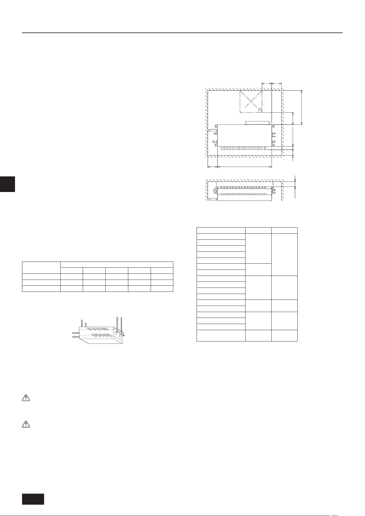
3.3. Securing installation and service
space
1. For hanging from the ceiling
(This is a reference view showing the least installation space.)
[Fig. 3.3.1] (Unit: mm [in])
<Top view>
450 (17-23/32)
B
D
INDOOR UNIT SIDE
200
[7-7/8]
<Front view>
B
Inspection hole
A
Control box
C
A
*1 Dimensions with which pipe connection can be handled at site
Model name A B
CMB-P104NU-G1
CMB-P105NU-G1
CMB-P106NU-G1
CMB-P108NU-G1
CMB-P1010NU-G1
CMB-P1013NU-G1
CMB-P1016NU-G1
CMB-P108NU-GA1
CMB-P1010NU-GA1
CMB-P1013NU-GA1
CMB-P1016NU-GA1
CMB-P104NU-GB1
CMB-P108NU-GB1
CMB-P108NU-HA1
CMB-P1010NU-HA1
CMB-P1016NU-HA1
CMB-P1016NU-HB1
[7-7/8]
A
C
648
[25-17/32]
1098
[43-1/4]
1110
[43-23/32]
648
[25-17/32]
1110
[43-23/32]
1098
[43-1/4]
B
[27-9/16]
(700)
250
9-27/32
[9-27/32]
[2-17/32][2-17/32]
64*1
100
[3-15/16]
On the side of outdoor unit piping
B
On the side of indoor unit piping
D
-
200
[7-7/8]
-
200
[7-7/8]
-
• Provide an inspection hole 450 mm [17-23/32 in] square in the ceiling surface as shown in [Fig.3.2.1].
• Install the unit in a suitable location (such as in the ceiling of a corridor or in
the bathroom etc) away from places regularly occupied. Avoid installing in
the center of a room.
• Ensure a pull out strength of at least 60 kg [133 LBS] per bolt for hanging
bolts.
• Be sure to install BC controllers level.
Warning:
Be sure to install the unit in a place that can sustain the entire weight.
If there is a lack of strength, it may cause the unit to fall down, resulting in
an injury.
Caution:
Be sure to install the unit level.
4
Page 5

3.4. Checking the installation site
Distance between BC controller and farthest indoor unit
Check that the difference of elevation between indoor and outdoor units and the
length of refrigerant piping are within the following limitations.
1. CMB-P104, 105, 106, 108, 1010, 1013, 1016G (In the case the outdoor
unit is 12.5-hp (P120 model) or less, and 16 or fewer ports are used.)
[Fig. 3.4.1]
A
I
A
H
H1
F
E
a
h1
L
h2
M
Outdoor unit
A
Indoor unit
C
Less than H=50 m [164 ft] (when the outdoor unit is higher than the indoor unit)
E
Less than H1=40 m [131 ft] (when the outdoor unit is lower than the indoor unit)
F
Twinning pipe (for Y Series) CMY-Y102S-G2
G
Combined pipe (CMY-R160-J1: optional)
H
Less than 110 m [360 ft]
I
Up to three units for 1 branch hole
K
Total capacity: less than 30 (but same in cooling/heating mode)
Less than h1=15 m [49 ft] (10 m [32 ft] or less for 200, 250 unit type)
L
Less than h2=15 m [49 ft]
M
Item Piping portion Allowable value
Total piping length
Longest piping length A+e
Length
Between outdoor unit and BC controller
Between indoor units and BC controller
Between indoor
and outdoor units
Above outdoor unit H Below 50 [164]
Below outdoor unit H1 Below 40 [131]
Between indoor units and BC controller
Between indoor units h2
Difference of elevation
Notes:
*1 Refer to “Restrictions on piping length” on P. 7.
*2 Please refer to the gure “Distance between BC controller and farthest
Indoor unit” when the distance between BC controller and farthest indoor unit exceeds 40 m [131ft]. (Not applicable to the P96 model indoor
unit)
*3 The values in the parentheses show the maximum piping length to be
followed when the connection capacity of the indoor unit is 72 or more.
*4 In the system to which indoor units of the P72 model or above are con-
nected, neither a branch joint nor a branch header may be used.
*5 Do not connect the P72 or P96 models of indoor units and other mod-
els of indoor units at the same port.
*6 Indoor units that are connected to the same branch joint cannot be si-
multaneously operated in different operation modes.
*7 When connecting multiple indoor units to one branch port, those in-
door units must be installed in the same room.
B
H
B
b
C
C
D
J
G
cde
CC
K
C
BC controller
B
P72 - P96 model: 2 ports merged.
D
Less than 40 m [131ft]
J
(Unit: m [ft])
A+B+a+b
+c+d+e
Not to exceed the
maximum refrigerant piping length
165 [541] or less
(Equivalent length
of 190 [623] or less)
A Below 110 [360]
e Below 40 [131] *2
h1
Below 15 [49]
(Below 10 [32])*3
Below 15 [49]
(Below 10 [32])*3
70 [229]
60 [196]
50 [164]
40 [131]
30 [98]
20 [65]
10 [32]
Distance between BC contoroller
and farthest indoor unit (m [ft])
0
0
Height difference between BC controller and farthest indoor
unit (m [ft])
15 [49]10 [32]5 [16]
2. CMB-P108, 1010, 1013, 1016GA, P104, 108GB, 1016HA, 1016HB
[Fig. 3.4.2]
h4
A
F
G
H
L
H1
N
M
*1
Outdoor unit
A
SUB BC controller
C
The Twinning Kit is connected inside the outdoor unit on the low-pressure side.
E
When outdoor units of different capacities are connected, connect the Twinning Kit to
the unit with a higher capacity.
Twinning pipe (for R2 series) CMY-R100VBK, CMY-R100XLVBK
F
Twinning pipe (for Y series) CMY-Y202-G2, CMY-Y102L-G2, CMY-Y102S-G2
G
Twinning pipe (CMY-R160-J1: optional)
H
Twinning pipe (for Y series) CMY-Y102S-G2
I
P72 - P96 model: 2 ports merged
J
Maximum of 3 units per a pair of ports
K
Total capacity of 30 or below
All units connected to the same port must be in the same operation mode.
Less than H=50 m [164 ft] (when the outdoor unit is higher than the indoor unit)
L
Less than H1=40 m [131 ft] (when the outdoor unit is lower than the indoor unit)
M
Less than h1=15 m [49 ft] (10 m [32 ft] or less for 36, 48 unit type)
N
Less than h2=15 m [49 ft]
O
E
A
F
A
<System that has more than 16 branching points>
G
B
C
I
H
a
DD DD
B
b
J
c d
K
MAIN BC controller
B
Indoor unit
D
D
e
C
D
GB
E
C
h2
*6
f
h1 h3 h1
O
D
(Unit: m [ft])
Item Piping portion Allowable value
Total piping length
F+G+A+B+C
+D+E+a+b
+c+d+e+f
Not to exceed the
maximum refrigerant piping length
*1
165 [541] or less
Longest piping length
F(G)+A+C+E+f
Length
Between outdoor unit and BC controller
Between indoor units and BC controller
Between outdoor unit
Between indoor
and outdoor units
Above outdoor unit H Below 50 [164]
Below outdoor unit H1 Below 40 [131]
Between indoor units and BC controller
Between indoor units h2
Between BC controller (main or sub)
and BC controller (sub)
Difference of elevation
F(G)+A Below 110 [360]
B+d or C+D
+e or C+E+f
F+G Below 5 [16]
h1
h3 Below 15 [49]
(Equivalent length
of 190 [623] or less)
Below 40 [131] *2
Below 15 [49]
(Below 10 [32])*3
Below 15 [49]
(Below 10 [32])*3
Between indoor units h4 Below 0.1 [5/16]
5
Page 6

Notes:
Distance between MAIN BC controller and farthest indoor unit
A system that has more than 16 branching points requires 2 to 3 BC controllers (main and sub) and 3 pipes to connect the main and the sub BC
controllers.
*1 Refer to “Restrictions on piping length” on P. 7.
*2 Please refer to the gure “Distance between main BC controller and
farthest Indoor unit” when the distance between main BC controller
and farthest indoor unit exceeds 40 m [131 ft]. (Not applicable to the
P96 model indoor unit)
*3 The values in the parentheses show the maximum piping length to be
followed when the connection capacity of the indoor unit is 72 or more.
*4 In the system to which indoor units of the P72 model or above are con-
nected, neither a branch joint nor a branch header may be used.
*5 When connecting two sub BC controllers, the total piping length must
be equal to or less than the maximum length as listed in the table
above.
*6 When connecting two sub BC controllers, install them in parallel.
*7 When the outdoor unit is 15-hp (P264 model) or more, use the HA-type
main BC controller. The GA-type BC controller cannot be connected to
the models between 27.5-hp (P264 model) and 30-hp (P288 model). The
G-type BC controller cannot be connected to the models between 15hp (P144 model) and 30-hp (P288 model).
*8 For Sub BC controller GB type, the connectable indoor unit capaci-
ties may sum to equal that of a P120 unit or less. However, if two sub
controllers are used the TOTAL sum of connectable units connected
to BOTH sub controllers must also not exceed that of a P120 unit.
For sub BC controller HB type, the connectable indoor unit capaci-
GB
ties may sum to equal that or a P120 unit or less. However, if two sub
controllers are used the TOTAL sum of connectable units connected to
BOTH sub controllers must also not exceed that of a P168 unit.
*9 Indoor units that are connected to the same branch joint cannot be si-
multaneously operated in different operation modes.
*10 Do not connect the P72 or P96 models of indoor units and other mod-
els of indoor units at the same port.
*11 When connecting multiple indoor units to one branch port, those in-
door units must be installed in the same room.
70 [229]
60 [196]
50 [164]
40 [131]
30 [98]
20 [65]
10 [32]
0
Distance between MAIN BC controller
0
and farthest indoor unit (m [ft])
Height difference between MAIN BC controller and farthest
indoor unit (m [ft])
15 [49]10 [32]5 [16]
6
Page 7

[Fig. 3.4.3]
Restrictions on piping length
PURY-P72/96THMU-A, PURY-P72/96YHMU-A
PURY-P72/96TJMU-A, PURY-P72/96YJMU-A
PURY-P216/240TSHMU-A, PURY-P216/240YSHMU-A
PURY-P216/240TSJMU-A, PURY-P216/240YSJMU-A
1000 [3280]
900 [2952]
800 [2624]
700 [2296]
600 [1968]
A
500 [1640]
400 [1312]
300 [984]
200 [656]
10
[32]20[65]30[98]40[131]50[164]60[196]70[229]80[262]90[295]
PURY-P120/144/168T (S) HMU-A, PURY-P120/144/168Y (S) HMU-A
PURY-P120/144/168T (S) JMU-A, PURY-P120/144/168Y (S) JMU-A
1000 [3280]
900 [2952]
800 [2624]
700 [2296]
1000 [3280]
900 [2952]
800 [2624]
700 [2296]
600 [1968]
A
500 [1640]
400 [1312]
300 [984]
100
110
[328]
B
[360]
200 [656]
10
[32]20[65]30[98]40[131]50[164]60[196]70[229]80[262]90[295]
B
100
[328]
110
[360]
PURY-P264/288TSJMU-A, PURY-P264/288YSJMU-A
1000 [3280]
900 [2952]
800 [2624]
700 [2296]
GB
600 [1968]
A
500 [1640]
400 [1312]
300 [984]
200 [656]
10
[32]20[65]30[98]40[131]50[164]60[196]70[229]80[262]90[295]
PURY-P192TSHMU-A, PURY-P192YSHMU-A
PURY-P192TSJMU-A, PURY-P192YSJMU-A
1000 [3280]
900 [2952]
800 [2624]
700 [2296]
600 [1968]
A
500 [1640]
400 [1312]
300 [984]
B
100
[328]
110
[360]
600 [1968]
A
500 [1640]
400 [1312]
300 [984]
200 [656]
10
[32]20[65]30[98]40[131]50[164]60[196]70[229]80[262]90[295]
PURY-P72-P234TGMU-A
1000 [3280]
900 [2952]
800 [2624]
700 [2296]
600 [1968]
A
500 [1640]
400 [1312]
300 [984]
100
110
[328]
B
[360]
200 [656]
10
[32]20[65]30[98]40[131]50[164]60[196]70[229]80[262]90[295]
Total piping length (m [ft])
A
100
110
[328]
B
Piping length between outdoor unit and BC controller (m [ft])
B
[360]
200 [656]
10
[32]20[65]30[98]40[131]50[164]60[196]70[229]80[262]90[295]
B
100
[328]
110
[360]
7
Page 8

4. Installing BC controller
14
B
4.1. Installing BC controllers
Installing hanging bolts
Install locally procured hanging bolts (threaded rod) following the procedure
given in the gure. The hanging bolt size is ø10 mm [13/32 in] (M10 screw).
To hang the unit, use a lifting machine to lift and pass it through the hanging
bolts.
Suspension bracket has an oval hole. Use a large diameter washer.
[Fig. 4.1.1] (Unit: mm [in])
Hanging method
A
B
<Top view>
[9/16]
Be sure to install the BC controllers level. Installing obliquely may
u
cause a risk of drain leakage. Use a level to check the unit’s level. If it
is oblique, loosen the xing nut and make an adjustment.
Caution:
Be sure to install the unit body level.
A
Hanging bolt ø10 [13/32] (eld-supplied) B Washer (eld-supplied)
A
A: Min.30 [1-3/16]
5. Connecting refrigerant pipes and drain pipes
GB
30
[1-3/16]
5.1. Pipe connecting method
Brazing
Caution:
Keep the ame out of contact with the cables and metal sheet when brazing the pipes.
- Failure to do so may result in burnout or malfunction.
When connecting pipes, satisfy the minimum insertion depth requirement for copper pipe joint, and the gap between the pipe outer wall and the joint inner wall as follows.
(Unit: mm)
Pipe size (D) Minimum insertion depth (B) Gap (A–D)
D A
5 or more, less than 8 6
8 or more, less than 12 7
12 or more, less than 16 8
16 or more, less than 25 10
25 or more, less than 35 12
35 or more, less than 45 14
0.05 to 0.35
0.05 to 0.45
0.05 to 0.55
• Silver braze the pipes in corrosive environments such as in which the concentration of sulphurous acid gas is high.
• Do not use a low-temperature brazing material as it is not strong enough.
• When re-brazing the connections, use the same brazing material.
• Paint the brazed sections after brazing.
• Use the proper ux based on the base material type, shape, brazing type, and brazing method.
Procedures
(1) Braze the pipes as shown in the gure below at the temperature appropriate for the brazing material.
After brazing, keep supplying a ow of nitrogen gas until the pipes become cool enough to be touched by hand. (Be careful not to burn yourself.)
(2) Completely remove the ux after brazing.
(After brazing, keep supplying a
ow of nitrogen gas until the brazed
section is cooled down to 200ºC or
lower.)
Notes:
• Keep the heated area to a minimum and braze the pipes at the appropriate temperature.
• To prevent a re, cover the pipes with a metal sheet and place a wet towel on the pipes.
• After brazing pipes, do not splash water on the pipes to cool them down.
• Avoid giving mechanical shock to the pipes until the brazed sections have solidied.
• Make sure to check the components of the antioxidant before use. The components must not corrode the pipes if mixed with the refrigerant or refrigerant
oil.
N
Cylinder
2
Stuff something in the pipe to keep air from entering the pipe.
Example of brazing pipes under nitrogen purge
Brazed section
Supply a ow of dry nitrogen gas at the rate
you slightly feel the ow (about 1 liter/minute).
8
Page 9

5.2. Connecting refrigerant pipes
1. Connect the liquid and gas pipes of each indoor unit to the same (correct)
end connection numbers as indicated on the indoor unit are connection section of each BC controller. If connected to wrong end connection numbers,
there will be no normal operation.
2. List indoor unit model names in the name plate on the BC controller control
box (for identication purposes), and BC controller end connection numbers
and address numbers in the name plate on the indoor unit side.
3. If the number of connected indoor units is less than the number of branch
holes, it does not matter which end connections you leave.
Seal unused end connections using are nuts with end caps just as they
were capped when shipped from the factory. Not replacing on end cap will
lead to refrigerant leakage.
4. When using twinning pipes (CMY-Y102S-G2, CMY-Y102L-G2, CMY-Y202G2), be sure to connect them level.
5. Be sure to have pipe expansion of indoor unit connecting port by cutting the
piping at the cutting point which depends on the indoor unit capacity.
6. Be sure to use non-oxidative brazing where necessary. If you do not use
non-oxidative brazing, it may clog the pipes.
7. After completing pipe connection, support the pipes to ensure that load is not
imparted to the BC controller’s end connections (particularly to the gas pipes
of indoor units).
Note:
Remove burr after cutting the piping to prevent entering the piping.
Check that there is no crack at the pipe expansion part.
[Fig. 5.2.1]
Warning:
When installing and moving the unit, do not charge it with refrigerant other
than the refrigerant (R410A) specied on the unit.
- Mixing of a different refrigerant, air, etc. may cause the refrigerant cycle to
malfunction and result in severe damage.
Caution:
• Use refrigerant piping made of phosphorus deoxidized copper and
copper alloy seamless pipes and tubes. In addition, be sure that the
inner and outer surfaces of the pipes are clean and free of hazardous
sulphur, oxides, dust/dirt, shaving particles, oils, moisture, or any other
contaminant.
- R410A is a high-pressure refrigerant and can cause the existing piping to
burst.
• Store the piping to be used during installation indoors and keep both
ends of the piping sealed until just before brazing. (Store elbows and
other joints in a plastic bag.)
- If dust, dirt, or water enters the refrigerant cycle, deterioration of the oil and
compressor failure may result.
• Apply a small amount of ester oil, ether oil, or alkyl benzene to ares. (for
indoor unit)
- Inltration of a large amount of mineral oil may cause the refrigerant oil to
deteriorate.
A
B
F
A
Indoor unit connecting port
A
Cutting point : ø9.52 (Liquid side) or ø15.88 (Gas side)
B
(Indoor unit model : bigger than P18)
Cutting point : ø6.35 (Liquid side) or ø12.7 (Gas side)
C
(Indoor unit model : P18 or smaller)
Cut the piping at the cutting point
D
Have pipe expansion of indoor unit connecting port
E
Field pipe
F
C
D
E
FA
Note:
Remove burr after cutting the piping to prevent entering the piping.
Check that there is no crack at the pipe expansion part.
GB
9
Page 10

1. Size of BC controller’s end connection piping
[Fig. 5.2.2]
BC CONTROLLER/MAIN BC CONTROLLER SUB BC CONTROLLER
Unit model Model name
PURY-P72
(BC CONTROLLER)
CMB-P104NU-G1
CMB-P105NU-G1
PURY-P96
CMB-P106NU-G1
CMB-P108NU-G1
CMB-P1010NU-G1
PURY-P120
CMB-P1013NU-G1
CMB-P1016NU-G1
High pressure
side (mm [in])
ø15.88 [5/8]
(Brazing)
ø19.05 [3/4]
(Brazing)
Low pressure
side (mm [in])
ø19.05 [3/4]
(Brazing)
ø22.2 [7/8]
(Brazing)
ø25.4 [1]
(Brazing)
PURY-P144
PURY-P168 73-108
(MAIN BC
CONTROLLER)
PURY-P192 109-126
CMB-P108NU-GA1
CMB-P1010NU-GA1
ø22.2 [7/8]
(Brazing)
ø28.58 [1-1/8]
(Brazing)
CMB-P1013NU-GA1
PURY-P216
CMB-P1016NU-GA1
Outdoor unit side
GB
PURY-P240
PURY-P264
PURY-P288
(MAIN BC
CONTROLLER)
CMB-P108NU-HA1
CMB-P1010NU-HA1
CMB-P1016NU-HA1
Indoor unit side
A
B
C
*1D
E
F
24-54 72-96 *3
To outdoor unit (MAIN BC CONTROLLER)
A
End connection (brazing)
B
BC controller (MAIN BC CONTROLLER / SUB BC CONTROLLER)
C
Reducer (accessory)
D
Less than 18
F
Combined piping kit (Model name: CMY-R160-J1)
G
Twinning pipe (Model name: CMY-Y102S-G2)
H
Up to three units for 1 branch hole; total capacity: below 30 (but same in cooling/heat-
I
ing mode)
G*2
EE
ø28.58 [1-1/8]
(Brazing)
ø9.52 [3/8]
(Flare)
H
EEIE
Indoor unit
E
ø34.93 [1-3/8]
(Brazing)
ø15.88 [5/8]
(Flare)
The size of BC controller’s branch piping is for 63 to 140 type indoor units.
Therefore, if you want to connect indoor units other than the above, connect piping following the procedures below.
*1. For connecting 06 to 18 type indoor units
Connect indoor units using the reducers supplied with BC controllers.
Note:
Use only the are nuts supplied with the BC controller.
*2. To connect a unit with a capacity of higher than 31.
After combining two branches using an optionally available piping kit
(CMY-R160-J1), connect indoor units.
*3. Connection of plural indoor units with one connection (or joint pipe)
• Total capacity of connectable indoor units: Less than 30 (Less than 96 with
joint pipe)
• Number of connectable indoor units: Maximum 3 Sets
• Twinning pipe: Use the twinning pipe for CITY MULTI Y Series (CMY-Y102S-
G2)
• Selection of refrigerant piping
Select the size according to the total capacity of indoor units to be installed
downstream.
(Unit: mm [in])
Total capacity of indoor units Liquid line Gas line
Below 54
55 to 72 ø19.05 [3/4]
ø9.52 [3/8]
ø15.88 [5/8]
73 to 96 ø22.2 [7/8]
Model name
Total capacity of
indoor units
High pressure
(gas) side (mm [in])
Low pressure (gas)
side (mm [in])
When a system that has more than 16 branching points, use BC controllersì
(main and sub) to connect the pipes.
below 72
ø15.88 [5/8]
(Brazing)
ø19.05 [3/4]
(Brazing)
ø22.2 [7/8]
ø19.05 [3/4]
(Brazing)
(Brazing)
CMB-P104NU-GB1
CMB-P108NU-GB1
127-144
CMB-P1016NU-HB1
ø28.58 [1-1/8]
(Brazing)
ø15.88 [5/8]
(Flare)
145-168
ø22.2 [7/8]
(Brazing)
ø9.52 [3/8]
(Flare)
*1 Use the supplied pipe.
2. Connecting to out side pipes
• For PURY-P72, 96, 120, 144, 168, 192, 216, 240, 264, 288
[Fig. 5.2.3] (Unit: mm [in])
High pressure/low pressure piping diagram
B
A
D
E
C
Connection pipe of outdoor unit (Low pressure)
A
Connection pipe of outdoor unit (High pressure)
B
Drain piping (O.D.
C
Connection pipe of indoor unit (Liquid)
D
Connection pipe of indoor unit (Gas)
E
32mm [1-1/4 in])
ø
Note:
Be sure to use non-oxidative brazing.
5.3. Refrigerant piping work
After connecting the refrigerant pipes of all indoor and outdoor units with the outdoor units’ stop valves remained fully closed, evacuate vacuum from the outdoor
units’ stop valve service ports.
After completing the above, open the outdoor units’ stop valves. This connects
the refrigerant circuit (between outdoor and BC controller) completely.
How to handle stop valves is described on each outdoor unit.
Notes:
• Before tightening the are nut, apply refrigerating machine oil lightly
over the valve are surface and its seating surface.
• Use two wrenches for pipe connection.
• After pipe connection, be sure to check that there is no gas leakage,
using a leak detector or soap-and-water solution.
• Before brazing the refrigerant piping, always wrap the piping on the main
body, and the thermal insulation piping, with damp cloths to prevent
heat shrinkage and burning the thermal insulation tubing. Take care to
ensure that the ame does not come into contact with the main body itself.
• Do not use leak-detection additives.
Warning:
Do not mix anything other than the specied refrigerant (R410A) into the
refrigerating cycle when installing or moving. Mixing air may cause the
refrigerating cycle to reach abnormally high temperature, resulting in burst
pipes.
Liquid side
(mm [in])
ø9.52 [3/8]
(Brazing)
ø12.7 [1/2]
(Brazing)
ø15.88 [5/8]
(Brazing)
10
Page 11

Caution:
Cut the tip of the indoor unit piping, remove the gas, and then remove the
brazed cap.
[Fig. 5.3.1]
[Fig. 5.5.1] (Unit: mm [in])
1
C
A
B
2
D
F
E
Cut here
A
A
B
Remove brazed cap
B
5.4. Insulating refrigerant pipes
Be sure to wind heat-resisting polyethylene form of more than 20 mm [13/16
in] in thickness onto both liquid and gas pipes and also put it onto the joints
between indoor unit and insulating material so that there will be no gaps. Incomplete insulation may cause excess condensation or heat losses. Pay careful attention, particularly when insulating above the ceiling.
[Fig. 5.4.1]
C
B
A
D
F
E
Locally procured insulating material for pipes
A
Bind here using band or tape.
B
Lap margin: more than 40 mm [1-19/32 in]
D
Unit side insulating material
F
Do not leave any opening.
C
E Insulating material (eld-supplied)
5.5. Drain piping work
1. Drain piping work
• Ensure that the drain piping is downward (pitch of more than 1/100) to the
outdoor (discharge) side. If it is impossible to take any downward pitch, use
an optionally available drain-up mechanism to obtain a downward pitch of
more than 1/100.
• Ensure that any cross-wise drain piping is less than 20 m [65 ft]. If the drain
piping is long, support it with metal brackets to prevent it from bending, warping, or vibrating.
• Connect the supplied drain hose to the discharge port on the unit body. Use
hard vinyl chloride pipes VP-25 (ø32 mm [1-1/4 in]) for drain piping (2).
Tighten the supplied drain hose onto the discharge port using the supplied
hose band. (For this, do not use any adhesive because the drain hose will
need to be removed for servicing at a later date.)
• Do not use any odor trap around the discharge port.
• Make sure to use the supplied hose band G to x the drain hose in place.
Using a commercially available hose band may cause damage to the natural
drain discharge port when tightend too much, resulting in water leakage.
A
A: 250 [9-27/32]
B
B: 1500-2000 [59-1/16-78-3/4]
Downward pitch of more than 1/100 B Insulating material
A
Supporting bracket
C
Drain hose (200 [7-7/8] long, accessory) F Tie band (accessory)
E
Hose band (accessory)
G
G
Drain discharge port
D
VP-25
• As shown in 3, install a collecting pipe about 100 mm [3-15/16 in] below the
drain ports and give it a downward pitch of more than 1/100. This collecting
pipe should be of VP-30.
• Set the end of drain piping in a place without any risk of odor generation.
• Do not put the end of drain piping into any drain where ionic gases are gen-
erated.
• Drain piping may be installed in any direction. However, please be sure to
observe the above instructions.
• When using an optionally available drain-up mechanism, follow its instruction
manual regarding its installation and use.
[Fig. 5.5.2]
3
A
D
VP-30
BB
C
BC controller
A
Indoor unit
B
Collecting pipe
C
Please ensure this length is at least 100 mm [3-15/16 in].
D
2. Discharge test
After completing drain piping work, open the BC controller panel, and test drain
discharge using a small amount of water. Also, check to see that there is no water leakage from the connections.
3. Insulating drain pipes
Provide sufcient insulation to the drain pipes just as for refrigerant pipes.
Caution:
Be sure to provide drain piping with heat inslation in order to prevent
excess condensation. Without drain piping, water may leak from the unit
causing damage to your property.
GB
6. Electrical work
Consult all related regulations and power companies beforehand.
u
Warning:
Electrical work should be handled by qualied electrical engineers in accordance with all related regulations and attached instruction manuals.
Special circuits should also be used. If there is a lack of power capacity or
a deciency in electrical work, it may cause a risk of electric shock or re.
Connect all wires securely.
u
• Fix power source wiring to control box by using buffer bushing for tensile
force (PG connection or the like).
[Fig. 6.0.1]
B
Control box
A
ø21 mm [27/32 in] hole (closed rubber bushing)
C
Transmission wiring
D
Never connect the power cable to the terminal board for control cables.
u
(Otherwise it may be broken.)
Be sure to wire between the control wire terminal boards for indoor
u
unit, outdoor unit and BC controller.
A
C
D
Power source wiring
B
Use non-polarized 2-wire as transmission cables.
Use 2-core shielding cables (CVVS, CPEVS) of more than 1.25 mm
2
[AWG16] in
diameter as transmission cables.
The switch capacity of the main power to BC controllers and the wire size are as
follows:
Switch (A)
Capacity Fuse
15 15 20 A
Molded case
circuit breaker
Earth leakage
breaker
20 A 30 mA
0.1 s or less
Wire size
1.5 mm2 [AWG15]
• For other detailed information, refer to the outdoor unit installation manual.
• Power supply cords of appliances shall not be lighter than design 245 IEC 53
or 227 IEC 53.
• A switch with at least 3 mm [1/8 in] contact separation in each pole shall be
provided by the Air conditioner installation.
Caution:
Do not use anything other than the correct capacity fuse and breaker. Using fuse, conductor or copper wire with too large capacity may cause a
risk of malfunction or re.
Ensure that the outdoor units are put to the ground. Do not connect the
earth cable to any gas pipe, water pipe, lightening rod or telephone earth
cable. Incomplete grounding may cause a risk of electric shock.
11
Page 12

7. Setting addresses and operating units
The address switch of each BC controller is set to “000” when shipped from the factory.
• Set the address switch to 1 + the address of the outdoor unit.
The BC controller address should generally be set to 1 + the address of the outdoor unit. However, if this would result in it having the same address as
u
another outdoor unit, set the address between 51 and 100, making sure that it is different from the address of other controllers.
• Please refer to the outdoor unit installation manual.
When connecting multiple indoor units to one branch port
u
• Indoor units connected to one branch port can only be operated in the same mode.
• When connecting multiple remote controllers, group setting is required.
8. Checklist after installation
Warning:
After the installation has been completed, check for refrigerant leaks.
- If the refrigerant leaks, oxygen starvation may result. If the leaked refrigerant comes in contact with a heat source, toxic gas will be generated.
After completion of installation work, check the item shown in the table below. If any abnormality is noticed, identify the problem and correct it. Leaving the problem
unattended may cause mechanical failure or malfunctions and raise safety risks.
No. Item to be checked
1 Check for refrigerant gas leakage.
GB
9. Test run
Before commencing a test run please check the following:
After installing, piping and wiring the indoor units and BC controllers, check to see again that there is no refrigerant leakage and no slack on power and
u
control cables.
Use a 500 V megger to check that there is an insulation resistance of more than 1.0 MΩ between the power terminal block and the ground. If it is less than
u
1.0 MΩ, do not operate the unit.
Caution:
Never measure the insulation resistance of the terminal block for any control cables.
10. Important information to be passed on to the end users
• Provide correct usage instructions to the end user. If the user is not present, provide them to the building owner, general constructor, or building manager.
• Important notes about safety is explained in section “Safety precautions” in this manual. Advise the user to follow them.
• Pass this Installation Manual to the user after completion of installation.
• Make sure that the manual is passed on to any future users.
• Perform a test run when the user is present.
12
Page 13

This product is designed and intended for use in the residential,
commercial and light-industrial environment.
Please be sure to put the contact address/telephone number on
this manual before handing it to the customer.
WT07612X01
HEAD OFFICE: TOKYO BLDG., 2-7-3, MARUNOUCHI, CHIYODA-KU, TOKYO 100-8310, JAPAN
 Loading...