

Mitsubishi Electric PQRY-P200YEM-A, PQRY-P250YEM-A, CMB-P104, PQHY-P200YEM-A, CMB-P105 Service Manual
...
Models
Service Handbook
PQRY-P200YEM-A, P250YEM-A
PQHY-P200YEM-A, P250YEM-A
CMB-P104, P105, P106, P108, P1010, P1013, P1016V-F
AIR CONDITIONERS CITY MULTI
HEAD OFFICE MITSUBISHI DENKI BLDG. MARUNOUCHI TOKYO 100-0005 TELEX J24532 CABLE MELCO TOKYO
New publication effective March 2004
Specifications subject to change without notice.
Service Handbook PQRY-P200YEM-A, P250YEM-A
CMB-P104, P105, P106, P108, P1010, P1013, P1016V-F
PQHY-P200YEM-A, P250YEM-A
Issued in March 2004 MEE03K209
Printed in Japan
Service Handbook WR2/WY YEM-A(R407C)

–1–
Contents
1 PRECAUTIONS FOR DEVICES THAT USE R407C REFRIGERANT .... 3
[1] Storage of Piping Material................................................................. 4
[2] Piping Machining............................................................................... 5
[3] Necessary Apparatus and Materials and Notes on Their Handling .. 6
[4] Brazing.............................................................................................. 7
[5] Airtightness T est................................................................................ 8
[6] Vacuuming ........................................................................................ 8
[7] Charging of Refrigerant..................................................................... 9
[8] Dryer ................................................................................................. 9
2 COMPONENT OF EQUIPMENT ........................................................... 10
[1] Appearance of Components ........................................................... 10
[2] Refrigerant Circuit Diagram and Thermal Sensor........................... 18
[3] Electrical Wiring Diagram................................................................ 20
[4] Standard Operation Data ................................................................ 26
[5] Function of Dip SW and Rotary SW................................................ 30
[6] External Input/Output Specifications............................................... 33
3 TEST RUN ............................................................................................. 34
[1] Before Test Run .............................................................................. 34
[2] Address Setting............................................................................... 38
[3] Test Run Method............................................................................. 43
4
...................................................................... 44
5 CONTROL.............................................................................................. 50
[1] Control of Heat Source Unit ............................................................ 50
[2] Control Box Cooling System............................................................ 54
[3] Control of BC Controller.................................................................. 57
[4] Operation Flow Chart...................................................................... 58
[5] List of Major Component Functions ................................................ 64
[6] Resistance of Temperature Sensor................................................. 67
6 REFRIGERANT AMOUNT ADJUSTMENT ............................................ 68
[1] Refrigerant Amount and Operating Characteristics ........................ 68
[2] Adjustment and Judgement of Refrigerant Amount ........................ 68
7 TROUBLESHOOTING ........................................................................... 72
[1] Principal Parts................................................................................. 72
[2] BC Controller Disassembly Procedure ........................................... 81
[3] Inverter and Compressor 96
[4] Trouble and Remedy of Remote Controller 101
[5] Self-diagnosis and Countermeasures Depending on the
Check Code Displayed ................................................................. 109
[6] LED Monitor Display ..................................................................... 132
8 PREPARATION, REPAIRS AND REFRIGERANT REFILLING
WHEN REPAIRING LEAKS ................................................................. 151
[1]
Location of Leaks: Extension Piping or Indoor Units (When Cooling)
... 151
[2]
Location of Leaks: Heat Source Unit (Cooling Mode)
.................... 151
[3] Location of Leaks: Extension Piping or Indoor Units
(Heating Mode) ............................................................................. 152
[4] Location of Leaks: Heat Source Unit (When Heating)................... 152
9 CHECK THE COMPOSITION OF THE REFRIGERANT..................... 153
0 DIFFERENCES BETWEEN THE PREVIOUS REFRIGERANT
AND THE NEW REFRIGERANT ......................................................... 155
[1] Chemical Characteristics .............................................................. 155
[2] Chances in Composition ............................................................... 155
[3] Pressure Characteristics............................................................... 156
A REFRIGERATOR OIL .......................................................................... 157
[1] Refrigerator Oil with HFC Based Refrigerants .............................. 157
[2] Influence of Contaminants ............................................................ 157
................................................................
....................................
GROUPING REGISTRATION OF INDOOR UNITS WITH M-NET
REMOTE CONTROLLER
–2–
Safety precautions
Before installation and electric work
Before installing the unit, make sure you read all
the “Safety precautions”.
The “Safety precautions” provide very important
points regarding safety. Make sure you follow
them.
This equipment may not be applicable to
EN61000-3-2: 1995 and EN61000-3-3: 1995.
This equipment may have an adverse effect on
equipment on the same electrical supply system.
Please report to or take consent by the supply
authority before connection to the system.
Symbols used in the text
Warning:
Describes precautions that should be observed to
prevent danger of injury or death to the user.
Caution:
Describes precautions that should be observed to
prevent damage to the unit.
Symbols used in the illustrations
: Indicates an action that must be avoided.
: Indicates that important instructions must be followed.
: Indicates a part which must be grounded.
: Indicates that caution should be taken with rotating parts.
(This symbol is displayed on the main unit label.)
<Color: Yellow>
: Indicates that the main switch must be turned off before
servicing. (This symbol is displayed on the main unit label.)
<Color: Blue>
: Beware of electric shock (This symbol is displayed on the
main unit label.) <Color: Yellow>
: Beware of hot surface (This symbol is displayed on the
main unit label.) <Color: Yellow>
: Please pay attention to electric shock fully because
this is not Safety Extra Low-Voltage (SELV) circuit.
And at servicing, please shut down the power supply
for both of Indoor Unit and Heat Source Unit.
Warning:
Carefully read the labels affixed to the main unit.
Warning:
• Ask the dealer or an authorized technician to install the air
conditioner.
- Improper installation by the user may result in water leakage,
electric shock, or fire.
• Install the air unit at a place that can withstand its weight.
- Inadequate strength may cause the unit to fall down, resulting
in injuries.
• Use the specified cables for wiring. Make the connections
securely so that the outside force of the cable is not
applied to the terminals.
- Inadequate connection and fastening may generate heat and
cause a fire.
• Prepare for typhoons and other strong winds and earthquakes and install the unit at the specified place.
- Improper installation may cause the unit to topple and result
in injury.
• Always use an air cleaner, humidifier, electric heater, and
other accessories specified by Mitsubishi Electric.
- Ask an authorized technician to install the accessories.
Improper installation by the user may result in water leakage,
electric shock, or fire.
• Never repair the unit. If the air conditioner must be
repaired, consult the dealer.
- If the unit is repaired improperly, water leakage, electric
shock, or fire may result.
• Do not touch the heat exchanger fins.
- Improper handling may result in injury.
• If refrigerant gas leaks during installation work, ventilate
the room.
- If the refrigerant gas comes into contact with a flame,
poisonous gases will be released.
• Install the air conditioner according to this Installation
Manual.
- If the unit is installed improperly, water leakage, electric
shock, or fire may result.
• Have all electric work done by a licensed electrician
according to “Electric Facility Engineering Standard” and
“Interior Wire Regulations”and the instructions given in
this manual and always use a special circuit.
- If the power source capacity is inadequate or electric work is
performed improperly, electric shock and fire may result.
• Securely install the cover of control box and the panel.
- If the cover and panel are not installed properly, dust or water
may enter the heat source unit and fire or electric shock may
result.
• When installing and moving the air conditioner to another
site, do not charge the it with a refrigerant different from
the refrigerant (R407C) specified on the unit.
- If a different refrigerant or air is mixed with the original
refrigerant, the refrigerant cycle may malfunction and the unit
may be damaged.
• If the air conditioner is installed in a small room, measures
must be taken to prevent the refrigerant concentration
from exceeding the safety limit even if the refrigerant
should leak.
- Consult the dealer regarding the appropriate measures to
prevent the safety limit from being exceeded. Should the
refrigerant leak and cause the safety limit to be exceeded,
hazards due to lack of oxygen in the room could result.
• When moving and reinstalling the air conditioner, consult
the dealer or an authorized technician.
- If the air conditioner is installed improperly, water leakage,
electric shock, or fire may result.
• After completing installation work, make sure that refrigerant gas is not leaking.
- If the refrigerant gas leaks and is exposed to a fan heater,
stove, oven, or other heat source, it may generate noxious
gases.
• Do not reconstruct or change the settings of the protection devices.
- If the pressure switch, thermal switch, or other protection
device is shorted and operated forcibly, or parts other than
those specified by Mitsubishi Electric are used, fire or
explosion may result.
• To dispose of this product, consult your dealer.
• The installer and system specialist shall secure safety
against leakage according to local regulation or standards.
- Following standards may be applicable if local regulation are
not available.
• Pay a special attention to the place, such as a basement,
etc. where refrigeration gas can stay, since refrigerant is
heavier than the air.
▲
▲
▲
▲
▲
ELV
–3–
11
11
1 PRECAUTIONS FOR DEVICES THAT USE R407C REFRIGERANT
Caution
Do not use the existing refrigerant piping.
• The old refrigerant and refrigerator oil in the existing
piping contains a large amount of chlorine which ma y
cause the refrigerator oil of the new unit to deteriorate.
• Contaminants on the inside of the refrigerant piping
may cause the refrigerant residual oil to deteriorate.
❇
JIS : Japanese Industrial Standard
❇❇
: Comparable to CU-DHP (CUPROCLIMA), Cu-bl
(AFNOR), C12200 (ASTN), SF-Cu (DIN)
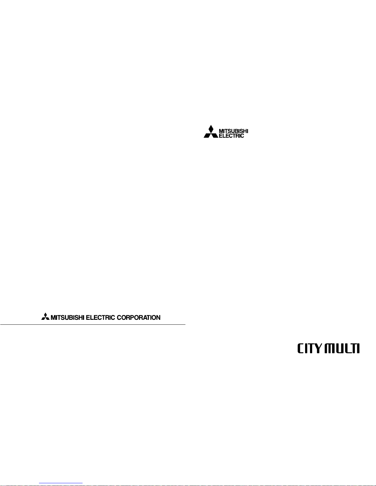
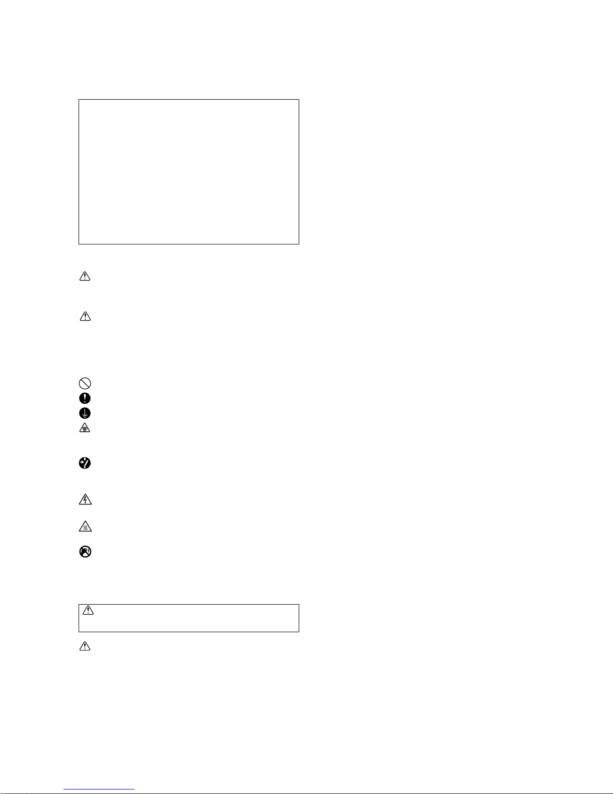
Store the piping to be used during installation indoors
and keep both ends of the piping sealed until just
before brazing. (Store elbows and other joints in a
plastic bag.)
• If dust, dirt, or water enters the refrigerant cycle,
deterioration of the oil and compressor trouble may
result.
Use ester oil, ether oil or alkylbenzene (small
amount) as the refrigerator oil to coat flares and
flange connections.
• The refrigerator oil will degrade if it is mixed with a
large amount of mineral oil.
Use liquid refrigerant to seal the system.
• If gas refrigerant is used to seal the system, the composition of the refrigerant in the cylinder will change
and performance may drop.
Do not use a refrigerant other than R407C.
• If another refrigerant (R22, etc.) is used, the chlorine
in the refrigerant may cause the refrigerator oil to deteriorate.
Use a vacuum pump with a reverse flow c hec k v alve.
• The vacuum pump oil may flow back into the refrigerant cycle and cause the refrigerator oil to deteriorate.
Do not use the following tools that have been used
with conventional refrigerants.
(Gauge manifold, c harge hose, gas leak detector, reverse flow check valve, refrigerant charge base,
vacuum gauge, refrigerant recovery equipment.)
• If the conventional refrigerant and refrigerator oil are
mixed in the R407C, the refrigerant may deteriorated.
• If water is mixed in the R407C, the refrigerator oil
may deteriorate.
• Since R407C does not contain any chlorine, gas
leak detectors for conventional refrigerants will not
react to it.
Do not use a charging cylinder.
• Using a charging cylinder may cause the refrigerant
to deteriorate.
Be especially careful when managing the tools.
• If dust, dirt, or water gets in the refrigerant cycle, the
refrigerant may deteriorate.
If the refrigerant leaks, recover the refrigerant in the
refrigerant cycle, then recharge the cycle with the
specified amount of the liquid refrigerant indicated
on the air conditioner.
• Since R407C is a nonazeotropic refrigerant, if additionally charged when the refrigerant leaked, the composition of the refrigerant in the refrigerant cycle will
change and result in a drop in performance or abnormal stopping.
Use refrigerant piping made of ❇❇C1220T phosphorus
deoxidized copper as specified in the
❇
JIS H3300
“Copper and copper alloy seamless pipes and tubes”.
In addition, be sure that the inner and outer surfaces of the pipes are clean and free of hazardous
sulphur, oxides, dust/dirt, shaving particles, oils,
moisture, or any other contaminant.
–4–
[1] Storage of Piping Material
(1) Storage location
Store the pipes to be used indoors. (Warehouse at site or owner’s warehouse)
Storing them outdoors may cause dirt, waste, or water to infiltrate.
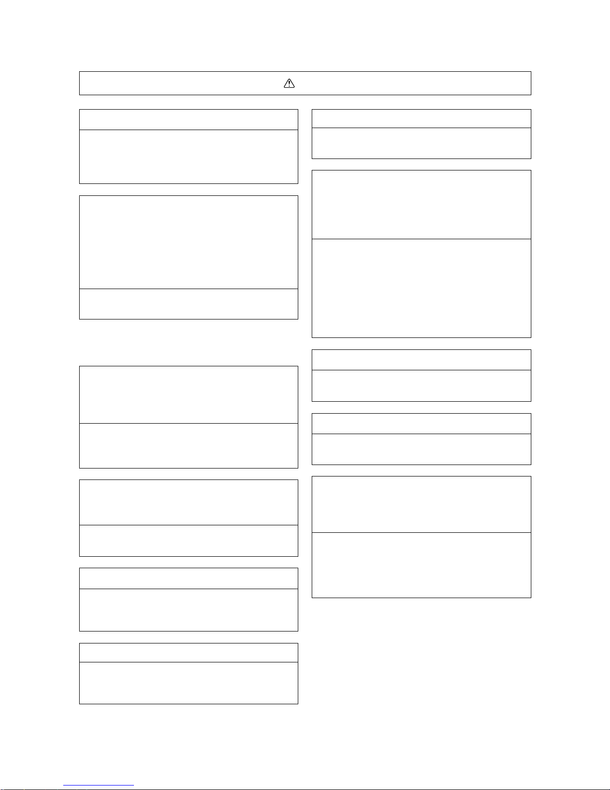
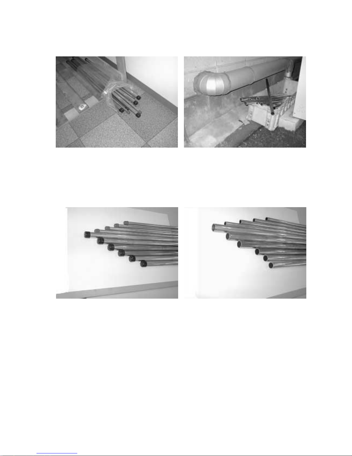
(2)
Both ends of the pipes should be sealed until immediately before brazing.
Wrap elbows and T’s in plastic bags for storage.
❇
The new refrigerator oil is 10 times more hygroscopic than the conventional refrigerator oil (such as Suniso). Water
infiltration in the refrigerant circuit may deteriorate the oil or cause a compressor failure. Piping materials must be
stored with more care than with the conventional refrigerant pipes.
OK
NG
OK
NG
Pipe sealing before storage
–5–
[2] Piping Machining
Use ester oil, ether oil or alkylbenzene (small amount) as the refrigerator oil to coat flares and flange connections.
Use only the necessary minimum quantity of oil.
Reason :
1. The refrigerator oil used for the equipment is highly hygroscopic and may introduce water inside.
Notes :
• Introducing a great quantity of mineral oil into the refrigerant circuit may also cause a compressor failure.
• Do not use oils other than ester oil, ether oil or alkylbenzene.
–6–
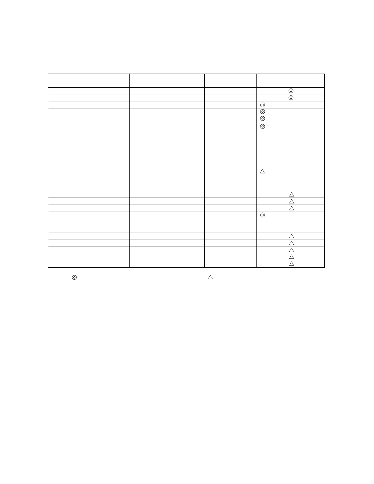
[3] Necessary Apparatus and Materials and Notes on Their Handling
The following tools should be marked as dedicated tools for R407C.
<<Comparison of apparatus and materials used for R407C and for R22>>
Apparatus Used Use R22 R407C
Gauge manifold Evacuating, refrigerant filling Current product
Charging hose Operation check Current product
Charging cylinder Refrigerant charging Current product Do not use.
Gas leakage detector Gas leakage check Current product Shared with R134a
Refrigerant collector Refrigerant collection R22 For R407C use only
Refrigerant cylinder Refrigerant filling R22
Vacuum pump Vacuum drying Current product
Vacuum pump with a check valve Current product
Flare tool Flaring of pipes Current product
Bender Bending of pipes Current product
Application oil Applied to flared parts Current product
Torque wrench Tightening of flare nuts Current product
Pipe cutter Cutting of pipes Current product
Welder and nitrogen cylinder Welding of pipes Current product
Refrigerant charging meter Refrigerant charging Current product
Vacuum gauge Checking the vacuum degree Current product
Symbols :
To be used for R407C only. Can also be used for conventional refrigerants.
Tools for R407C must be handled with more care than those for conventional refrigerants. They must not come into contact
with any water or dirt.
Identification of dedicated use for R407C
:Record refrigerant
name and put brown
belt on upper part of
cylinder.
Can be used by
attaching an adapter
with a check valve.
Ester oil or Ether oil or
Alkybenzene (Small
amount)
–7–
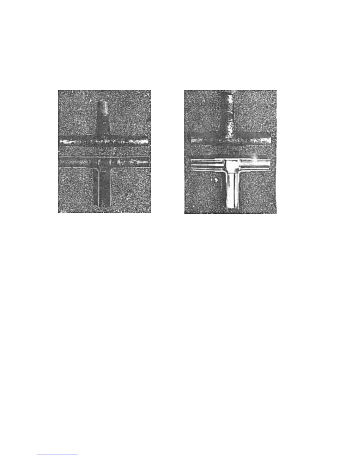
[4] Brazing
No changes from the conventional method, but special care is required so that foreign matter (ie. oxide scale, water, dirt,
etc.) does not enter the refrigerant circuit.
Example : Inner state of brazed section
When non-oxide brazing was not used When non-oxide brazing was used
Items to be strictly observed :
1. Do not conduct refrigerant piping work outdoors on a rainy day.
2. Apply non-oxide brazing.
3. Use a brazing material (BCuP-3) which requires no flux when brazing between copper pipes or between a copper pipe
and copper coupling.
4. If installed refrigerant pipes are not immediately connected to the equipment, then br az e and seal both ends of them.
Reasons :
1. The new refrigerant oil is 10 times more hygroscopic than the conventional oil. The probability of a machine failure if
water infiltrates is higher than with conventional refrigerant oil.
2. A flux generally contains chlorine. A residual flux in the refrigerant circuit may generate sludge.
Note :
• Commercially available antioxidants may have adverse effects on the equipment due to its residue, etc. When
applying non-oxide brazing, use nitrogen.
–8–
[5] Airtightness Test
No changes from the conventional method. Note that a refrigerant leakage detector for R22 cannot detect R407C
leakage.
Items to be strictly observed :
1. Pressurize the equipment with nitrogen up to the design pressure and then judge the equipment’s airtightness, taking
temperature variations into account.
2. When investigating leakage locations using a refrigerant, be sure to use R407C.
3. Ensure that R407C is in a liquid state when charging.
Reasons :
1. Use of oxygen as the pressurized gas may cause an explosion.
2. Charging with R407C gas will lead the composition of the remaining refrigerant in the cylinder to change and this
refrigerant can then not be used.
Note :
• A leakage detector for R407C is sold commercially and it should be purchased.
[6] Vacuuming
1. Vacuum pump with check valve
A vacuum pump with a check valve is required to prevent the vacuum pump oil from flowing back into the refrigerant
circuit when the vacuum pump power is turned off (power failure).
It is also possible to attach a check valve to the actual vacuum pump afterwards.
2. Standard degree of vacuum for the vacuum pump
Use a pump which reaches 65Pa or below after 5 minutes of operation.
In addition, be sure to use a vacuum pump that has been properly maintained and oiled using the specified oil. If the
vacuum pump is not properly maintained, the degree of vacuum may be too low.
3. Required accuracy of the vacuum gauge
Use a vacuum gauge that can measure up to 65Pa. Do not use a general gauge manifold since it cannot measure a
vacuum of 65Pa.
4. Evacuating time
• Evacuate the equipment for 1 hour after 650Pa has been reached.
• After envacuating, leave the equipment for 1 hour and make sure the that vacuum is not lost.
5. Operating procedure when the vacuum pump is stopped
In order to prevent a backflow of the vacuum pump oil, open the relief valve on the vacuum pump side or loosen the
charge hose to drawn in air before stopping operation.
The same operating procedure should be used when using a vacuum pump with a check valve.
Halide torch R22 leakage detector
NG
NG
–9–
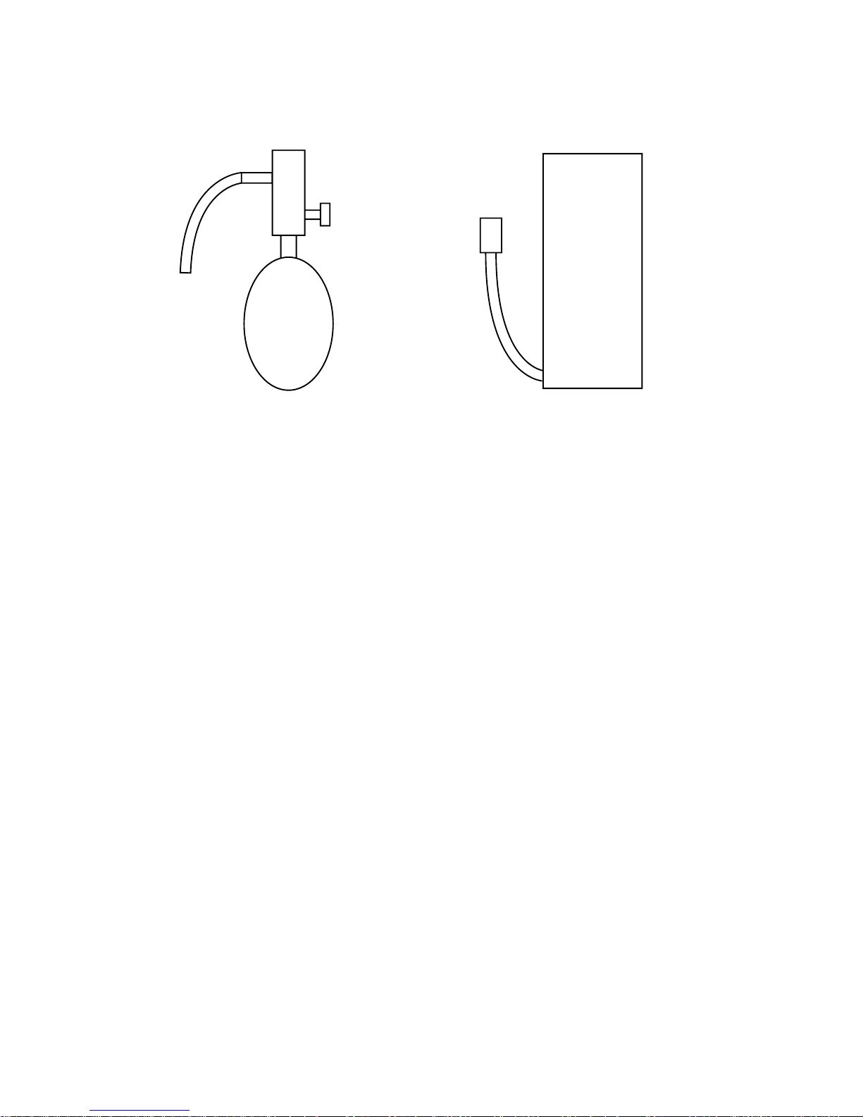
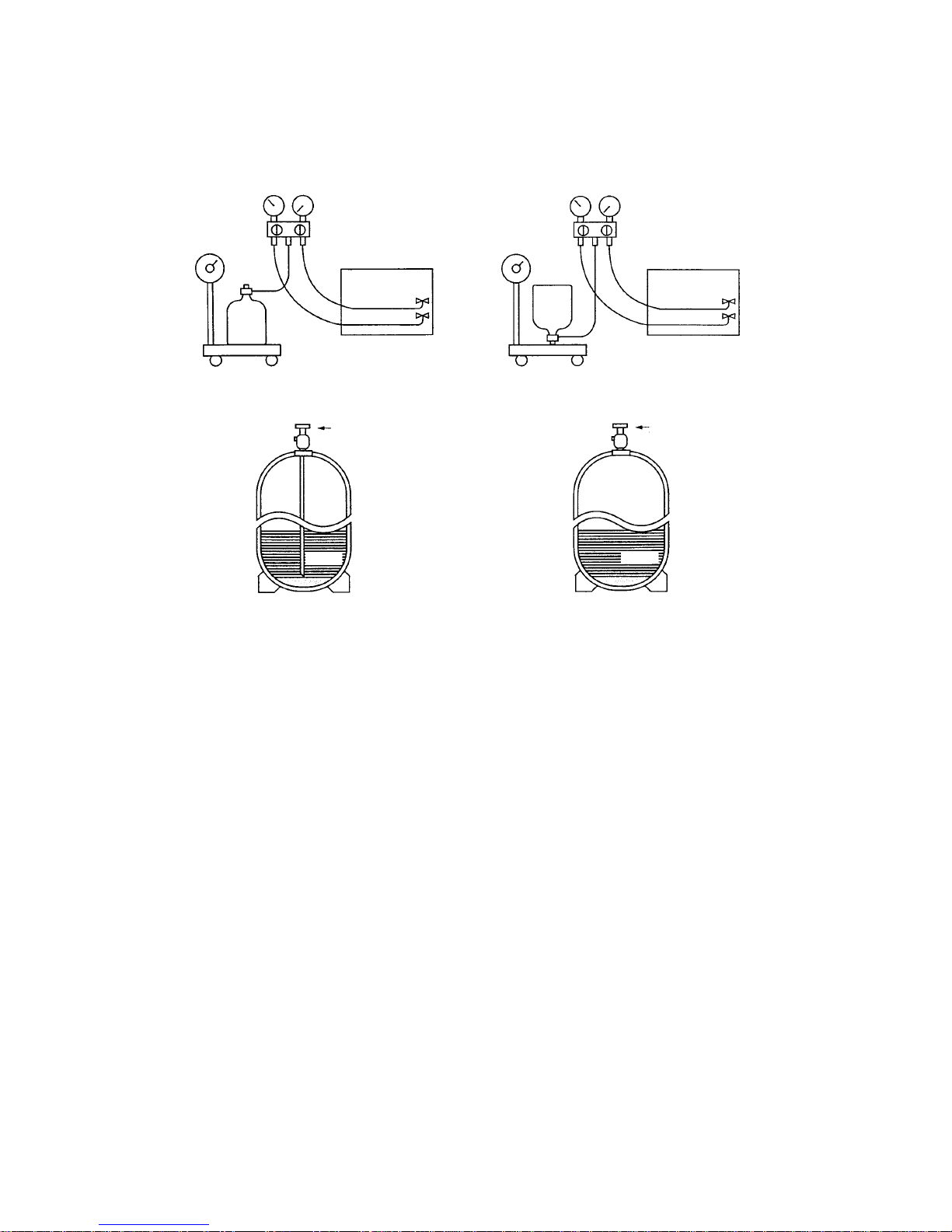
[7] Charging of Refrigerant
R407C must be in a liquid state when charging, because it is a non-azeotropic refrigerant.
For a cylinder with a syphon attached For a cylinder without a syphon attached
Cylinder color identification R407C-brown Charged with liquid refrigerant
Reasons :
1. R407C is a mixture of 3 refrigerants, each with a different evaporation temperature. Therefore, if the equipment is
charged with R407C gas, then the refrigerant whose evapor ation temper ature is closest to the outside temperature is
charged first while the rest of refrigerants remain in the cylinder.
Note :
• In the case of a cylinder with a syphon, liquid R407C is charged without turning the cylinder up side down. Chec k the
type of cylinder before charging.
[8] Dryer
1. Replace the dryer when the refrigerant circuit is opened (Ex. Change the compressor, full gas leakage). Be sure to
replace the dryer with a CITY MULTI Series WR2 (PQRY) (For use with R407C).
If any other product is used, the unit will be damaged.
2. Opening the refrigerant circuit after changing to a new dryer is less than 1 hour. The replacement of the dryer should
be the last operation performed.
Cylin-
der
Cylin-
der
Valve
Valve
Liquid
Liquid
–10–
22
22
2 COMPONENT OF EQUIPMENT
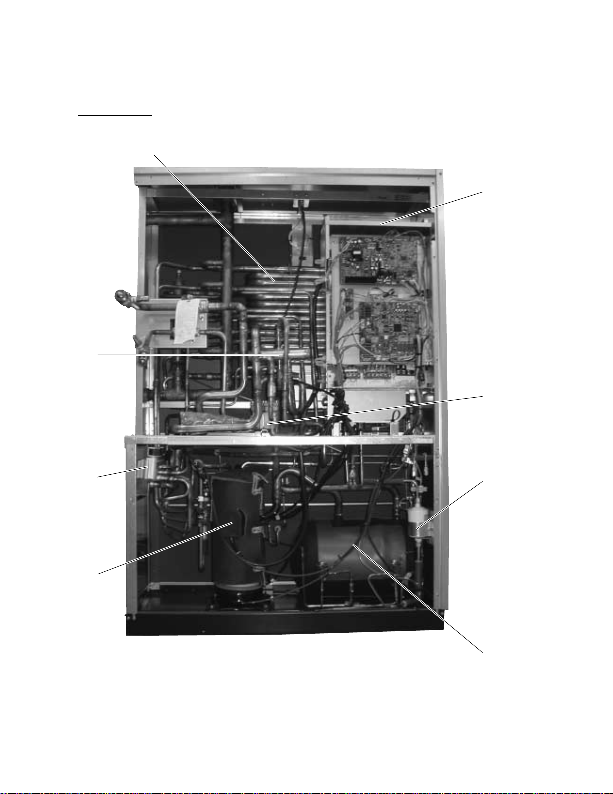
[1] Appearance of Component
• PQRY
s
Heat source unit
Heatexchanger
Control Box
CV
Block
Drier
Accumulator
Compressor
SV
Block
4-way
Valve
–11–
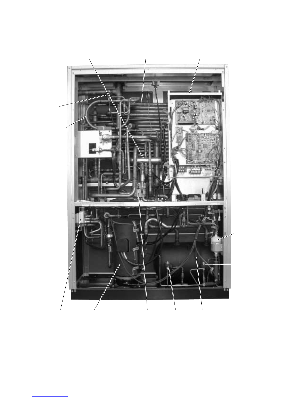
• PQHY
Heat exchanger4-way valve
LEV1
Sub-cool
coil
SV block Compressor CV block
Control box
S LEV Accumulator
LEV2
Drier
–12–
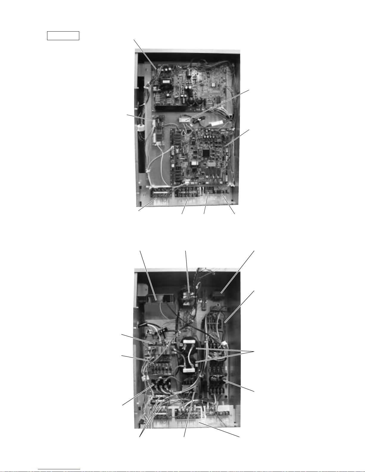
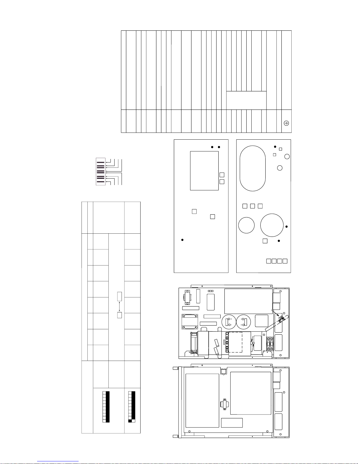
Control Box
INV board
RELAY
board
Transformer
(T01)
MAIN
board
Terminal block TB7
Transmission (Centralized Control)
Terminal block TB8
UNIT ON/OFF,
Pump inter lock
Terminal block TB1A
Power Source
Terminal block
TB3 Transmission
Cooling fan
(MF1)
DC reactor
(DCL)
Choke coil
(L2)
Fuse
(F3)
Noise
Filter
Magnetic Contactor (52C)
Intelligent Power
Module (IPM)
G/A board
Diode
stack
(DS)
Capacitor
(C2, C3)
Front View
Inner View
SNB board
(Back Side)
Fuse
(F5, F6)
–13–
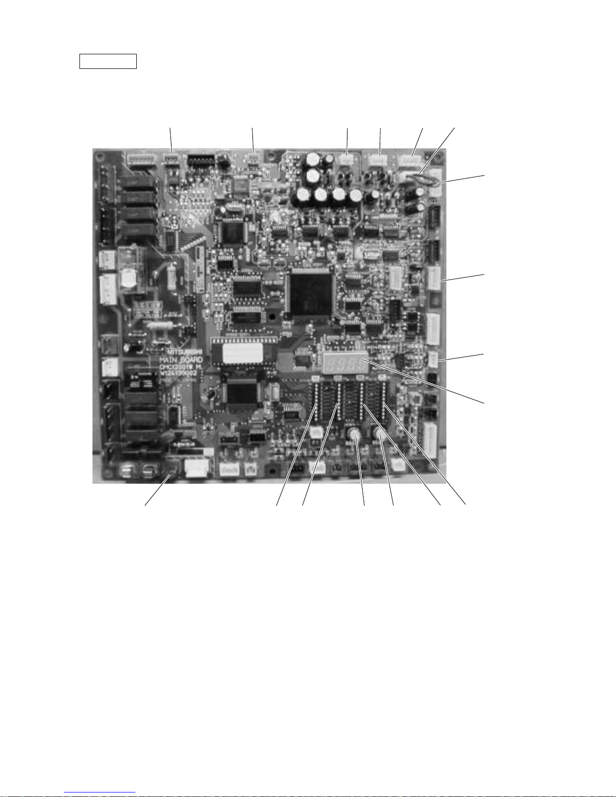
MAIN board
CNTR CNVCC4 CNS1 CNS2 CN40 CN41
CNVCC3
CN51
CN3D
LD1
Service LED
SW1SW2
SWU1SWU2
SW3SW4CN20
Power source
for control (5V)
Power source
for control
1-2 30 V,
1-3 30 V,
4-6 12 V,
5-6 5 V
–14–
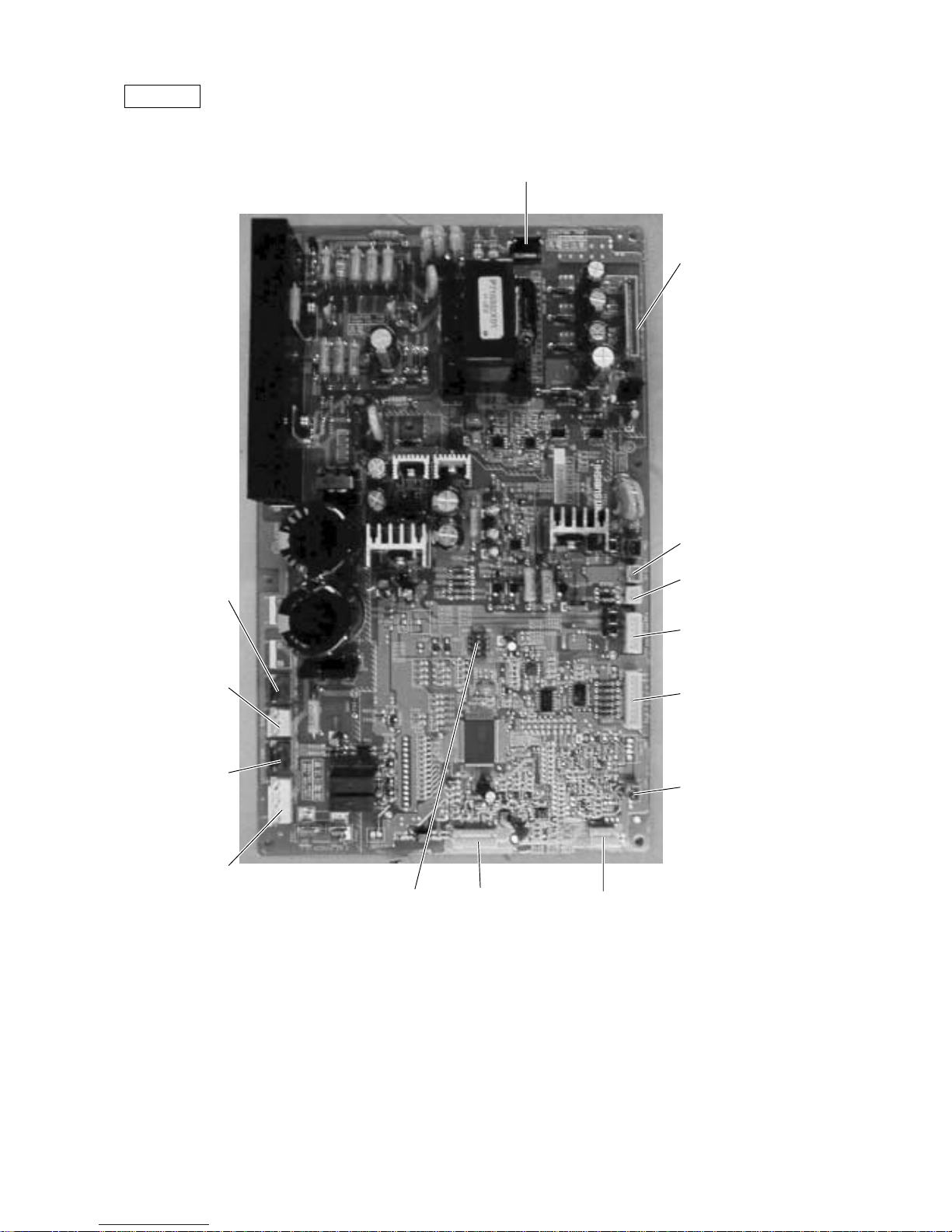
INV board
CNDR2
Output to
G/A board
CNTH
CN15V2
Power supply
for IPM control
CNACCT
CNAC2
Power
source
1 L2
3 N
5 G
CN52C
Control for
52C
CNFAN
Control
for MF1
CNR
CNRS2
Serial transmission
to MAIN board
SW1
CNVDC
1-4
DC-560V
CNVCC4
Power supply (5V)
CNL2
Choke coil
CNVCC2
Power supply
1-2 30V, 1-3 30V
4-6 12V, 5-6 5V
–15–
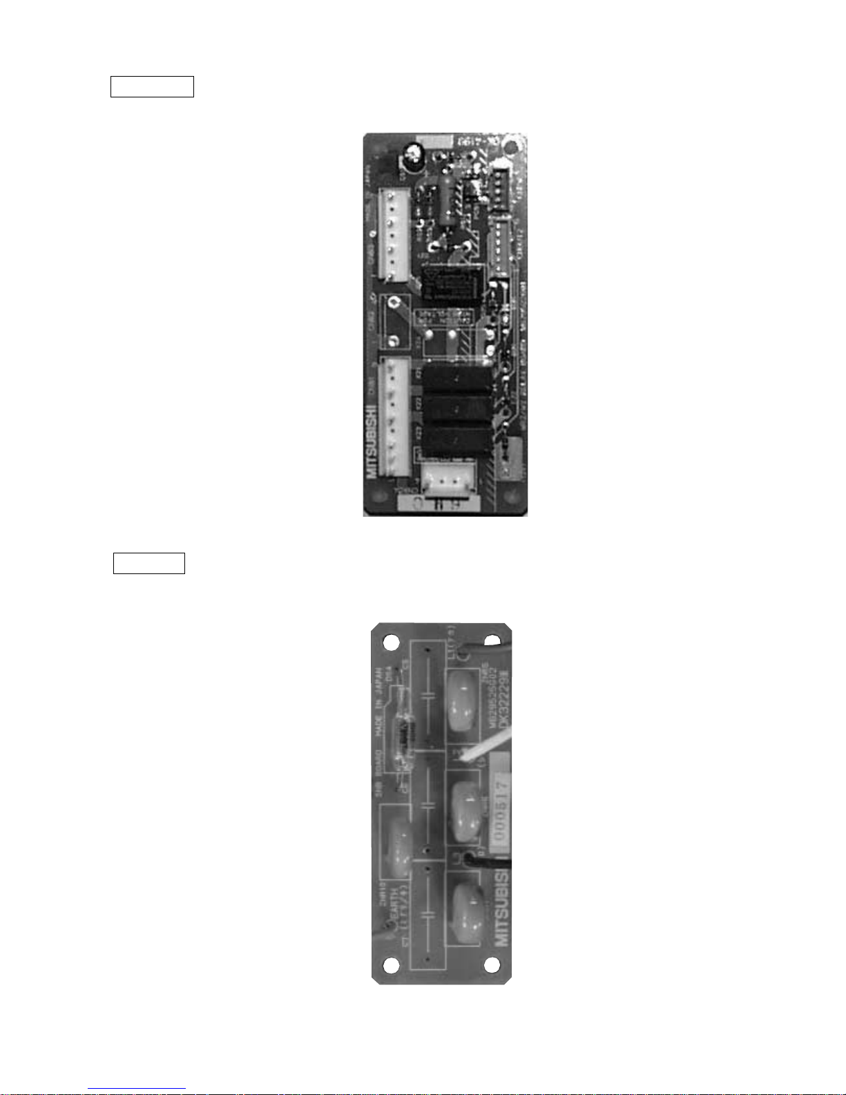
RELAY board
SNB board
–16–
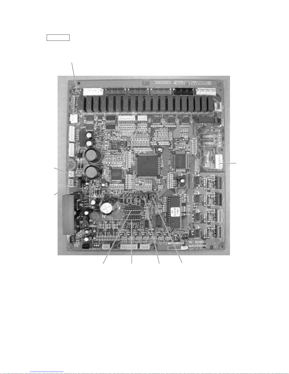
BC controller
BC board
SW4 SW5 SW2 SW1
CN12
Power
supply
1 EARTH
3 N
5 L
CN02
M-NET
transmission
CN03
CNTR
–17–
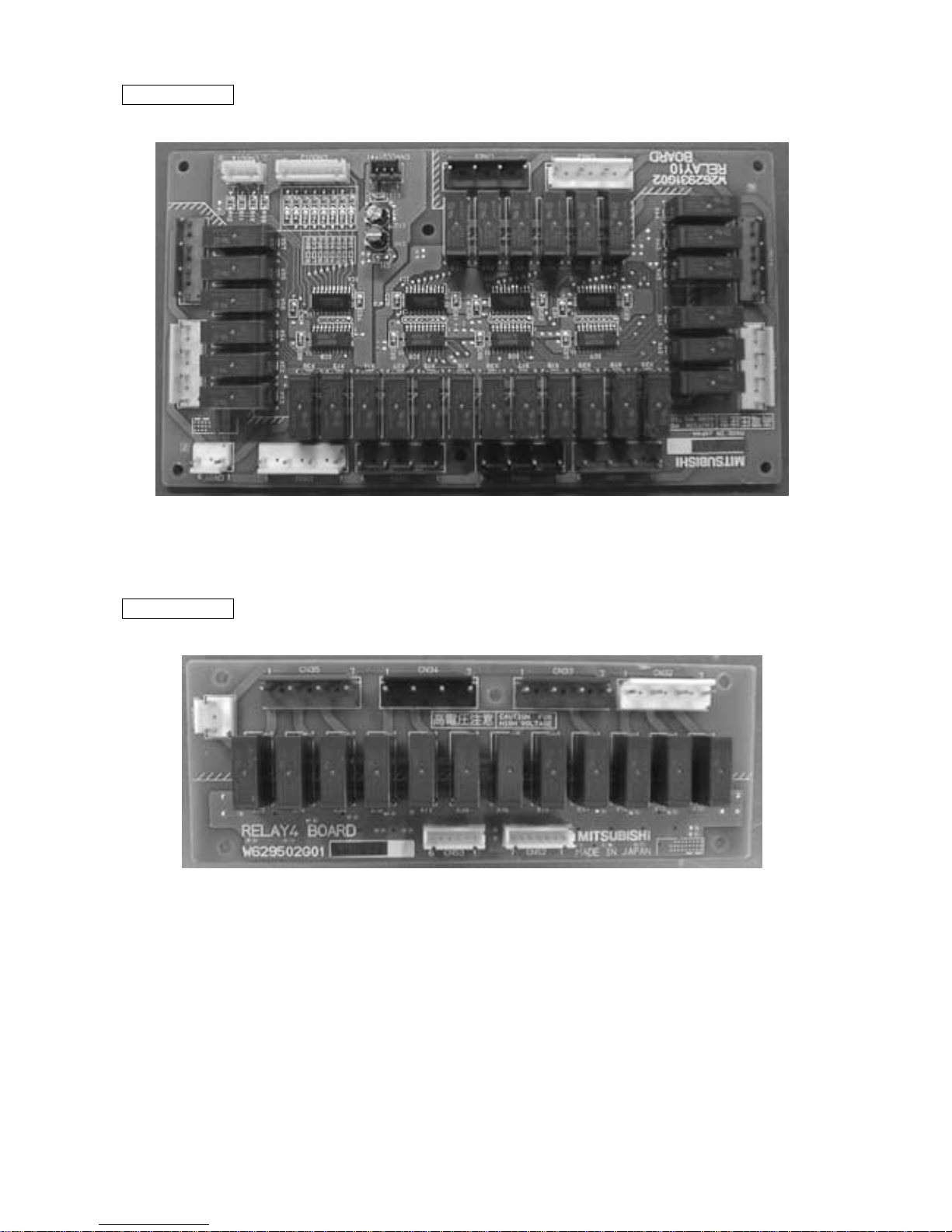
RELAY 10 board
RELAY 4 board
–18–
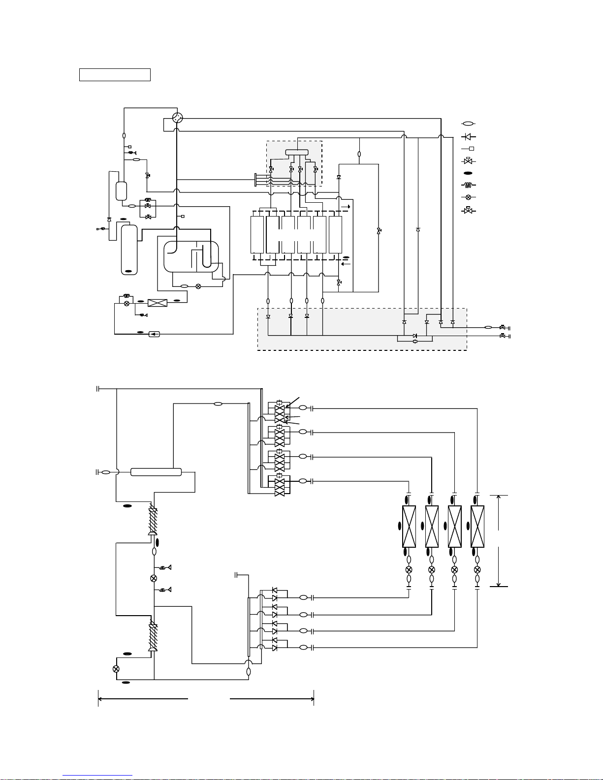
[2] Refrig
• PQRY
erant Circuit Diagram and Thermal Sensor
Heat source unit
TH1
Oil
separator
Compressor
CV1
ST6
CP1
ST5
SP1
ST2
4way valve
ST4
SLEV
Accumulator
TH10
SV73
Air heat exchanger
CP4
Water
circulating
High pressure
High pressure
sensor
switch
CV9
CV8
Drier
TH2
TH9
TH INV
LEV2
ST7b ST7cST7a
Low presser sensor
TH6
CV7
CV10
CV5
CV4
CV6
SV71
Orifice
SV72
ST7d
SV6
SV5
SV4
SV3
Solenoid Valves
Block
Check Valves Block
CV11
ST8
Distributor
BV2
BV1
ST1
CV3
CV2
SV1
SV2
CJ2
Water heat exchanger
(Double coil type)
TH23
TH21
TH22
LEV
SVC
SVA
SVB
Indoor
units
BC controller
CMB-P104V-E
Gas/liquid separator
63HS1
LEV1
63HS3
LEV3
TH12
TH11
TH15
TH16
: Strainer
: Check valve
: Service port
: Solenoid valve
: Thermal sensor
: Capillary
:
Liner valve expansion
: Ball valve
ST
CV
SP
SV
TH
CP
LEV
BV
–19–
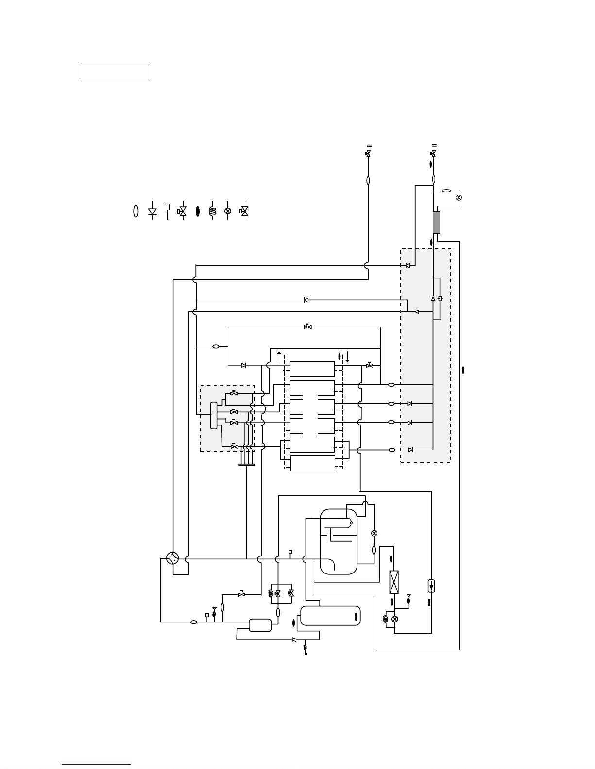
• PQHY
Heat source unit
TH5
TH7
TH8
SP1
ST2
4way valve
High pressure
sensor
Oil
separator
ST5
SV73
ST6
CP1
SV1
SV2
CJ2
TH1
CV1
High pressure
switch
Compressor
ST4
SLEV
Accumulator
TH10
Air heat exchanger
CP4
TH INV
LEV2
TH2
Low presser sensor
Drier
TH9
Solenoid Valves
Block
CV11
ST8
Check Valves Block
CV9
CV8
CV10
Water
circulating
ST7b ST7cST7a ST7d
CV7
SV72
TH6
SV71
SV6
SV5
SV4
SV3
Distributor
Orifice
CV4
CV6
BV2
BV1
ST1
ST9
ST10
CV3
Water heat exchanger
(Double coil type)
LEV1
SCC
: Strainer
: Check valve
: Service port
: Solenoid valve
: Thermal sensor
: Capillary
:
Liner valve expansion
: Ball valve
ST
CV
SP
SV
TH
CP
LEV
BV
–20–
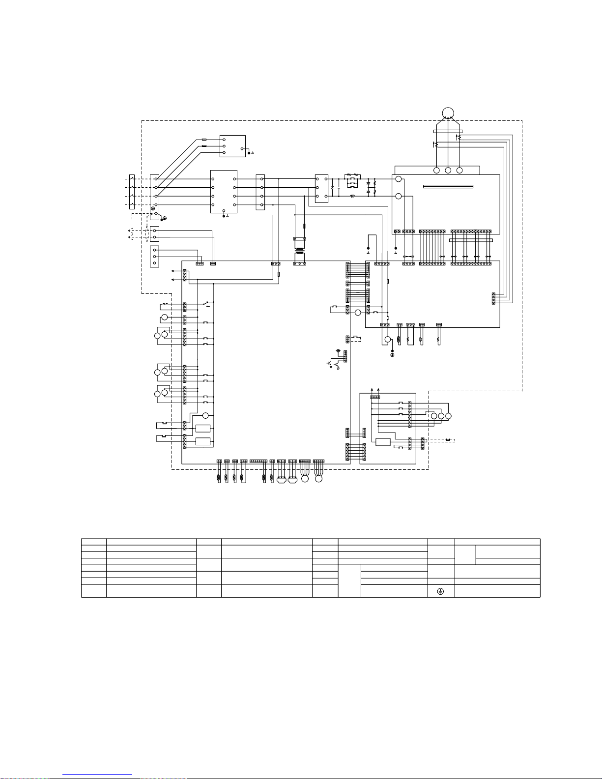
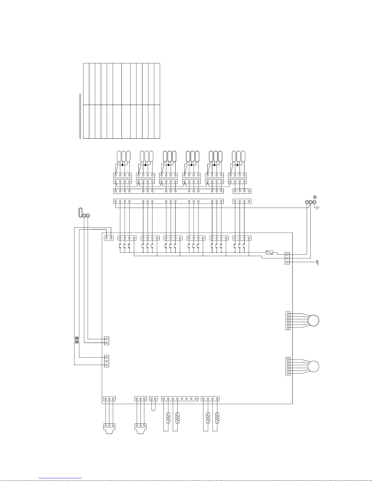
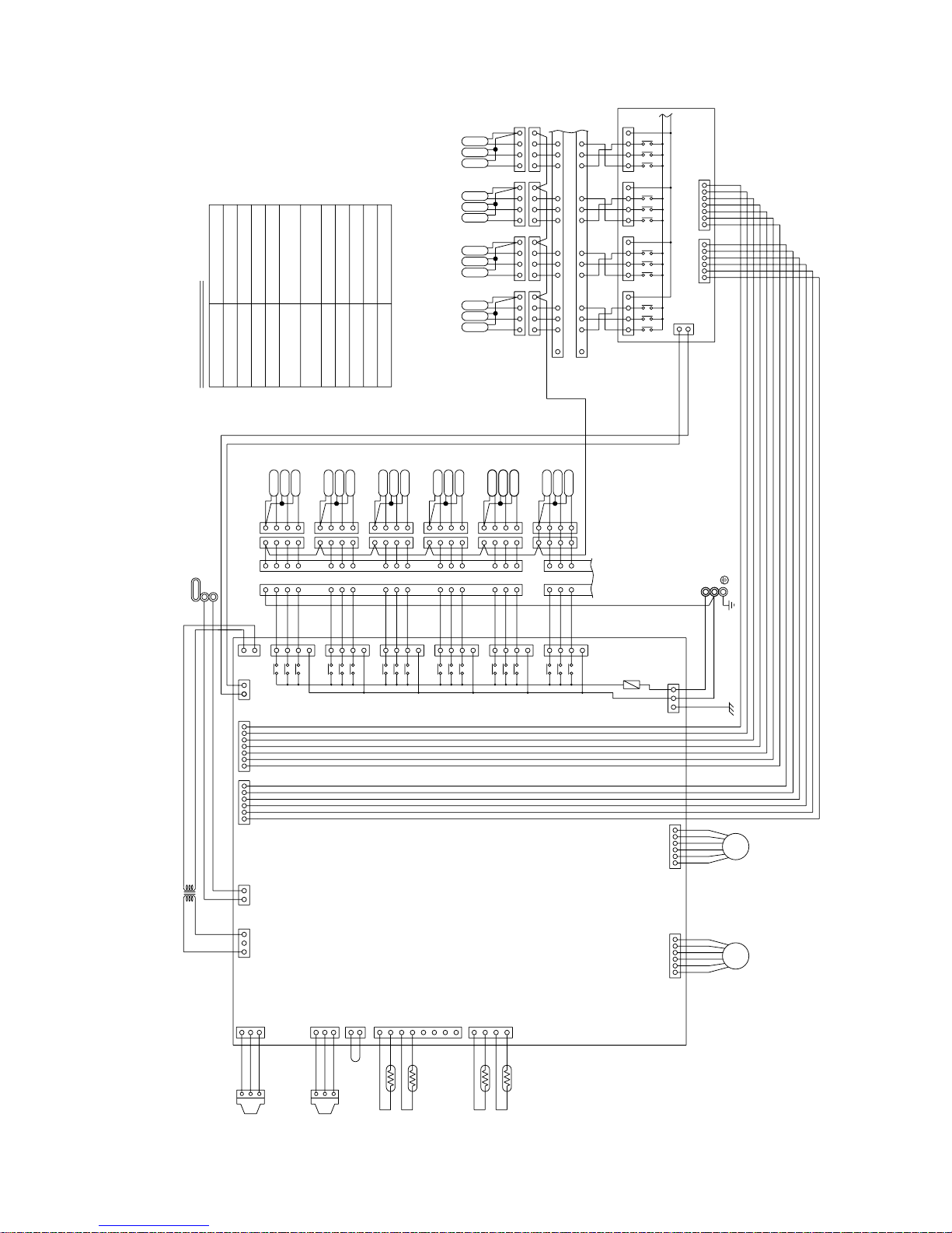
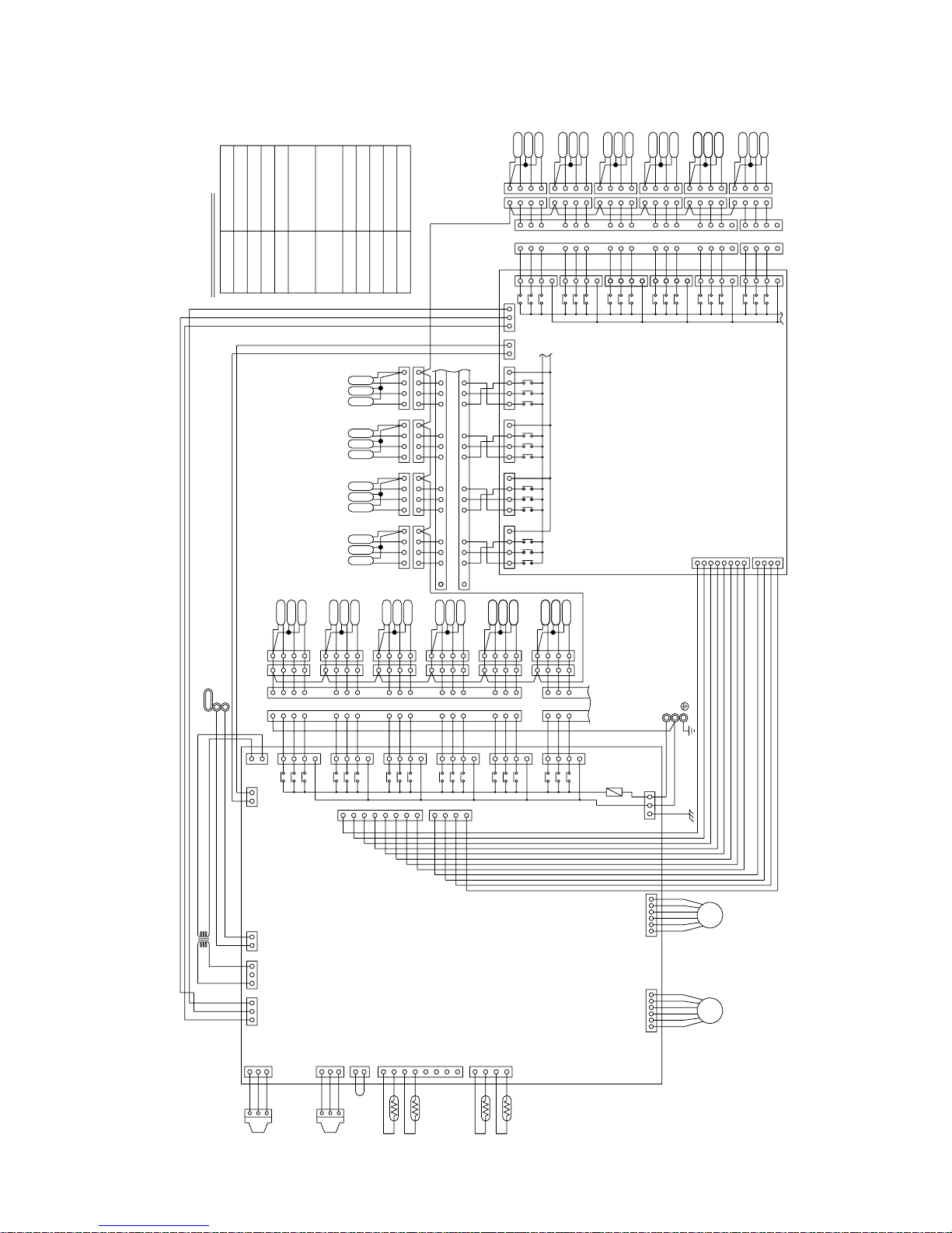
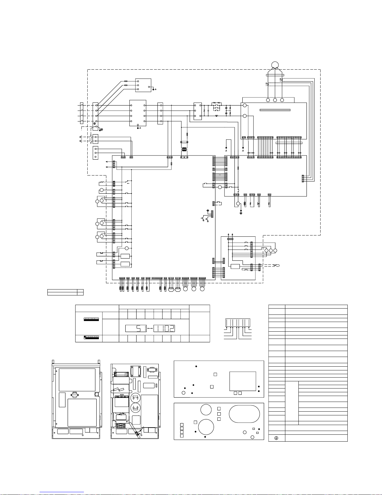
[3] Electrical Wiring Diagram
• PQRY
Black
White
Red
Black
White
Red
(4P)
CNAC3
X10
FB1
SNB board
EARTH
BOX BODY
8A F
600VAC
F5
8A F
600VAC
F6
L3
L1
L2
Green
ACCT
-U
(4P)
CNACCT
4
Brown
Orange
(14P)
CN15V1
(9P)
CNDR1
IPM
FB2
(G/A board)
Gate amp board
N
P
WVU
4
3
2
1
5
Gray
White
Black
Purple
Orange
Yellow
987612345987612345 14131110 12
121011 1314
(9P)
CNDR2
543216789 54321
4321
(4P)
CNDC1
Refer to the service handbook
about the switch operations.
L2
S
M2
M1
L1
1
L3
PE
R6
2
3
4
1
2
1
7
6
5
4
3
2
1
5
6
3
1
4
2
2
3
5
1
F01
250VAC
2A F
13
CN20
(3P)
221
CNVCC4
(2P)
31
CNS1
(2P)
CN51
(5P)
CNAC2
(5P)
2
CNS2
(3P)
1
CNX10
(3P)
CNR
(3P)
2
CN52C
(3P)
3
CNVDC
(4P)
CNTH
(2P)
12V
N
5:SW3-3 OFF:water freeze signal
4:Compressor ON/OFF
N
L3
(MAIN board)
TB1A
L2
F1
250VAC
2A F
L1
PE
White
Red
Black
Blue
Green/
Yellow
Connect to
Indoor and
remote
controller
TB3
M1
M2
TB7
DS
-
+
ZNR4
C1
R5
R1
52C
+
+
DCL
C2
C3
R2
R3
T01
F3
250VAC
1A F
CNTR1
White
V
Red
Black
3
212112234
132126178392
2
3
4
1
2
1
7
6
5
4
3
2
1
5
6
1
2
3
52C
X02
X01
X10
CNRS2
(7P)
CNVCC4
(2P)
CNVCC3
(6P)
CNVCC2
(6P)
CNRS3
(7P)
CNFAN
(3P)
THHS
CNTR
(3P)
CN15V2
(14P)
CNL2
(2P)
CN30V
(2P)
MF1
R7
L2
Power circuit board
(INV board)
BOX BODY
Controller Box
Red
Brown
Black
White
Red
Blue
Control circuit board
CNOUT1
(6P)
L2
L3
N
BOX BODY
TB1B
L1
White
Red
Black
Blue
NF
Red
White
Black
Blue
L1
L2
L3
N
L1
L2
L3
N
6
5
4
3
2
1
Terminal
Block
Terminal
Block
Noise
Filter
Diode
stack
BOX BODY
BOX BODY
12
(2P)
CNE
BOX BODY
ACCT
-W
Inverter
U
W
MC1
Motor
(Compressor)
(4P)
CNPW
4
3
2
1
123
4
CNAC4
(4P)
1
2
3
4
(9P)
CN81
5
6
7
8
9
X21
X22
X23
SV72
SV71
SV73
1
3
5
7
(7P)
CN83
X25
4
3
2
1
TB8
63PW
CNOUT2
(6P)
1
2
3
4
5
6
AC1AC4
(to CNAC3)
(3P)
CN3D
2
3
1
TH6
THINV
SLEV
321
TH1
321
63HS 63LS
122121 32112
(5P)
CNLV1
(3P)
CNL
(3P)
CNH
(2P)
CN01
(8P)
CN02
(3P)
CN03
5432132132121876345
LEV2
(5P)
CNLV2
54321
26W
SV5
SV6
SV3
SV4
21S4
SV2
63H
CH1
SV1
(to CNAC4)
AC4
AC1
4
1
2
3
X01
CN34
(6P)
6
5
4
3
2
1
X04
X05
(3P)
CN32
X02
1
2
3
2
1
(3P)
CN33
3
X07
X06
1
2
3
4
5
6
(6P)
CN36
4
5
6
CN37
1
2
3
CN38
(3P)
X09
X08
1
2
3
(6P)
1
2
3
4
5
CNRT1
(5P)
4
3
2
1
(4P)
CN63PW
CN06
(2P)
CN09
(2P)
CN12
(2P)
detection
circuit
detection
circuit
circuit
detection
DEMAND
RELAY board
Freeze protect
switch
High pressure
switch
Crank case heater
(Compressor)
Unit ON/OFF
Pump interlock
TH9TH10 TH2
ON :trouble signal
Ferrite core
Discharge pipe temp. detect
Saturation evapo. temp. detect
TH2
TH1
TH6 OA temp. detect
Electronic expansion valve(Oil return)SLEV
THINV
TH10
TH9
Compressor shell temp.
High pressure liquid temp.
THHS
heat exchanger for inverter
Outlet temp. detect of
50/60Hz
380/400/415V
3N
~
Power source
~
~
~
<SYMBOL EXPLANATION>
Symbol
DCL
ACCT-U,W
52C
ZNR4 Varistor
DC reactor (Power factor improvement)
Current Sensor
Magnetic contactor (Inverter main circuit)
N a m e
Fan motor (Radiator panel)MF1
Solenoid valve (Discharge--suction bypass)SV1,SV2
4--way valve
21S4
Symbol
63HS
SV3~6
Solenoid valve
(Heat exchanger capacity control)
SV71~73
Solenoid valve
(Heat exchanger capacity control)
LEV2
High pressure sensor
63LS Low pressure sensor
Electric expansion valve
(Heat exchanger for inverter)
N a m e
Choke coil (Transmission)L2
IPM Intelligent power module
N a m eSymbol
Thermistor
Thermistor
Symbol N a m e
Radiator panel temp. detect
Aux. relay
X1~10
X21~25
FB1~2
Earth terminal
–21–
• PQRY
21S4
SV1
SV2
SV3
SV4
SV72SV71
SV5
SV6
SV73
SSR
<Operation of self-diagnosis switch (SW1) and LED display>
<LED display>
Display
Relay output
display
(Lighting)
Check display1
(Blinking)
(at factory shipment)
Display at LED lighting (blinking) Remarks SW1 operation
FLAG1 FLAG2
FLAG3 FLAG4
FLAG5 FLAG6 FLAG7
FLAG8
Display the address and error code by turns
Always
lighting
FLAG8 always lights
at microcomputer
power ON
During
compressor
run
Crankcase
heater
51
1102
FLAG1
FLAG2
FLAG3
FLAG4
FLAG8
FLAG7
FLAG6
FLAG5
ON:1
OFF:0
1 2 3 4 5 6 7 8 9 10
ON:1
OFF:0
1 2 3 4 5 6 7 8 9 10
❇
Please refer to the service handbook about other switch settings of LED display.
LD1
INV board
MAIN board
RELAY
board
TB8
TB1A
TB3
TB7
T01
G/A board
IPM
C1
ZNR4
THHS
DCL
ACCT
R2
C2
C3
R3
NF
52C
MF1
L2
R5
R1
R7
F3
R6
DS
F6
F5
TB1B
TB8
TB3
TB7
TB1A
SNB
board
FB1~2
Ferrite core
Earth terminal
Aux. relay
L2
Discharge pipe temp. detect
Saturation
evapo. temp.
detect
Thermistor
TH2
TH1
TH6
OA temp. detect
(Heat exchanger capacity control)
Solenoid valve
(Heat exchanger capacity control)
(Heat exchanger for inverter)
Solenoid valve
SV3~6
High pressure sensor
Low pressure sensor
63LS
63HS
SLEV
Choke coil (Transmission)
Intelligent power module
IPM
Electronic expansion valve
Electronic expansion valve (Oil return)
LEV2
Fan motor (Radiator panel)
SV1, SV2 Solenoid valve (Discharge-suction bypass)
4-way
valve21S4
Varistor
Name
Symbol
DCL
(Power factor improvement)
< Symbol explanation >
DC reactor
ACCT-U, W
Current Sensor
ZNR4
(Inverter main circuit)
52C
MF1
Magnetic contactor
X1~10
SV71~73
X21~25
THINV
TH10
TH9
Compressor shell temp.
High pressure liquid temp.
THHS
Radiator panel tem
p. detect
heat exchanger for inverter
Outlet temp. detect of
< Controller box internal layout >
(Upside)
(Underside)
< Unit internal layout >
SV73
SV1
(Upside)
(Underside)
SEPARATOR
BOX
CONTROLLER
63LS
63HS
TH10
TH1
63H
SV2
SLEV
LEV2
TH9
ACCUMULATOR
MC
OIL
SV71SV72
INVERTER
26W
21S4
TH2
THINV
TH6
SV6
SV5
SV4
SV3
–22–
Symbol explanation
F01
250VAC
6.3A F
T6
T2
T3
T4
T5
T1
PE
3
2
1
3
2
1
EARTH
Fuse AC250V 6.3A F
F01
1
2
142
3
4
3
432
1
432
1
SV6C
SV6A
SV6B
1
234
1
234
123
4
1
234
123
4
123
4
123
4
123
4
123
4
SV5C
SV5A
SV5B
SV4B
SV4A
SV4C
SV3B
SV3A
SV3C
SV2B
SV2A
SV2C
123
4
161514
765
142
3
131211
10
9
8
423
TerminalT1~6
Terminal block
(for Transmission)
TB02
Terminal block
(for power source)
TB0
Note:TB02 is terminal block for transmission.
Never connect power line to it.
Solenoid valve
Solenoid valve
Solenoid valve
Expansion valve
Thermister sensor
Transformer
NameSymbol
SV1~6A
SV1~6B
SV1~6C
TR
TH11,12,15,16
LEV1,3
PS1,3 Pressure sensor
Transmission line
Shield wire
~220V~240V 50/60Hz
Power source
CONT.board
LEV1
161514
131211
10
9
8
765
1
SV1C
SV1A
SV1B
3
1
CNTR
CN02
CN12
153
753
1
753
1
753
1
753
1
753
1
753
1
TR
X2
X1
X30
X4
X3
X31
X6
X5
X32
X8
X7
X33
X10X9X34
X12
X11
X35
}
}
DC 30V
654321564321
LEV3
1
2
3
CNP1
123
CNP3
211234567
8
432
1
12321
CN03
CN13
CN10
CN11
CN07 CN05
L
N
TH11
TH12
TH15
TH16
PS1
PS3
22V
TB02
M2
M1
CN26
CN27
CN28
CN29
CN30
CN31
TB01
220~240V
1 CMB-P104, P105, P106V-F
–23–
Symbol explanation
F01
250VAC
6.3A F
T6
T7T8T9T10
T1
T2
T3
T4
T5
PE
3
2
1
3
2
1
EARTH
Fuse AC250V 6.3A F
F01
SV6B
SV6A
SV6C
123
4
1
234
33
2
1
2
1
1
2
34
1
2
34
1
2
34
1
2
34
1
2
34
1
2
34
1
2
34
1
2
34
SV7B
SV8B
SV9B
SV10B
SV7A
SV8A
SV9A
SV10A
SV7C
SV8C
SV9C
SV10C
131415
101112
9
78
6
5
4
4
87
6
5
12 11 10
915 14 13
16
16
RELAY4 Board
161514
765
142
3
131211
10
9
8
161514
765
142
3
10
9
8
131211
4
4
4
4
4
3
3
3
3
3
2
2
2
2
2
1
1
1
1
1
SV5C
SV5A
SV5B
SV4B
SV4A
SV4C
SV3B
SV3A
SV3C
SV2B
SV2A
SV2C
SV1C
SV1A
SV1B
123
4
2341234
234
234
1
1
1
TerminalT1~10
Power source
}
L
N
~220V~240V 50/60Hz
TB0
TB0
Terminal block
(for Transmission)
Solenoid valve
Solenoid valve
Solenoid valve
Terminal block
(for power source)
Pressure sensor
Expansion valve
Thermister sensor
Transformer
NameSymbol
SV1~10
SV1~10B
SV1~10C
TR
TH11,12,15,16
LEV1,3
PS1,3
Note:TB02 is terminal block for transmission.
Never connect power line to it.
Transmission line
Shield wire
CONT.board
CN38
1
3
1
CNTR
CN50
CN51
7654321123456
CN02
CN12
1
53
753
1
753
1
753
1
753
1
753
1
753
1
3
TR
X2
X1
X30
X4
X3
X31
X6
X5
X32
X8
X7
X33
X10X9X34
X12
X11
X35
}
DC 30V
6
54321
6
54321
LEV3 LEV1
1
2
3
CNP1
1
2
3
CNP3
2
1
1
234
5
6
7
8
432
1
12321
CN03
CN13
CN10
CN11
CN07 CN05
TH11
TH12
TH15
TH16
PS1
PS3
22V
TB02
M2
M1
CN26
CN27
CN28
CN29
CN30
CN31
TB01
220~240V
7654321123456
CN35
CN32
CN33
CN34
CN39
3
1
X14
X13
X36
X37
X15
X16
X18
X17
X38
X39
X19
X20
CN52CN53
57315315315133 3
2 CMB-P108, P1010V-F
777
–24–
Symbol explanation
EARTH
1
2
3
1
2
3
PE
TH11,12,15,16
T6
T2
T3
T4
T5
T1
T7
T8T9
T10
T16
T12
T13
T14
T15
T11
F01
250VAC
6.3A F
RELAY10 board
CONT.board
CN39
13
135
CN12
CNOUT3
CNOUT1
13571357135713571357135
7
135
7
135
7
135
7
135
7
135
7
753
1
1357 1357 1357
13
21
CNVCC2
3
X54
X57
X53
X52
X56
X55
CN45
CN44
CN42
CN43
X49
X50
X46
X47
X51
X48
123
8765432
1
4
CNOUT2
CNOUT4
CN41
CN40
X41
X44
X40
X43
X42
X45
CN34
CN35
X20
X18
X19
X17
X39
X38
3
CNVCC1
12
X16
X15
X37
X36
X13
X14
X2
X1
X30
X4
X3
X31
X6
X5
X32
X8
X7
X33
X10X9X34
X12
X11
X35
}
}
DC 30V
654321564321
LEV3 LEV1
123
CNP1
123
CNP3
211234567
8
432
1
12321
CN03
CN02
CN13
CN10
CN11
CN07 CN05
33
CN33
1357
CN32
TH11
TH12
TH15
TH16
PS1
PS3
22V
TR
TB02
M2
M1
CN38
CN26
CN27
CN28
CN29
CN30
CN31
TB01
220~240V
3
1
CNTR
4
1
2
3
4
5
6
7
8
3
2
1
Note1:TB02 is terminal block for transmission.
Never connect power line to it.
TB0
TB0
Terminal block
(for Transmission)
Solenoid valve
Solenoid valve
Solenoid valve
Terminal block
(for power source)
Pressure sensor
Expansion valve
Thermister sensor
Transformer
NameSymbol
SV1~16A
SV1~16B
SV1~16C
TR
LEV1,3
PS1,3
Shield wire
Transmission line
Power source
~220V~240V 50/60Hz
N
L
T1~16 Terminal
1
2
1233
432
1
432
1
SV6C
SV6A
SV6B
1
234
1
234
123
4
1
234
123
4
123
4
123
4
123
4
123
4
SV5C
SV5A
SV5B
SV4B
SV4A
SV4C
SV3B
SV3A
SV3C
SV2B
SV2A
SV2C
123
4
16
15
14
765
142
3
131211
10
9
8
423
16
15
14
131211
10
9
8
765
1
SV1C
SV1A
SV1B
432 1432 143 1432 1
432 1432 1432
2
1432 1
131415 101112 9 78654
487 6512 11 10 915 14 13
124
3
432
1
432
1
SV16C
SV16A
SV16B
1
234
1
234
123
4
1
234
123
4
123
4
123
4
123
4
123
4
SV15C
SV15A
SV15B
SV14B
SV14A
SV14C
SV13B
SV13A
SV13C
SV12B
SV12A
SV12C
123
4
161514
7
6
51423
13
121110
9
8
231
SV11C
SV11A
SV11B
124
3
161415
131112
10
798
654
16
16
SV10C
SV10A
SV10B
SV9C
SV9A
SV9B
SV8C
SV8A
SV8B
SV7C
SV7B
SV7A
Fuse AC250V 6.3A F
F01
3 CMB-P1013, P1016V-F
–25–
(5P)
CNRT1
High pressure
switch
Freeze protect
switch
circuit
detection
circuit
detection
5
4
3
2
1
(3P)
CN38
3
2
1
63H
26W
X10
Black
White
Red
(4P)
CNAC3
12345
(5P)
TH7 TH8
(2P)
CN12
12
THINV
12345
LEV1
FB1
SNB board
EARTH
BOX BODY
8A F
600VAC
F5
8A F
600VAC
F6
L3
L1
L2
Green
ACCT
-U
PQHY-P250YEM-A
PQHY-P200YEM-A 30A
50A
No fuse breaker
(4P)
CNACCT
4
Brown
Orange
(14P)
CN15V1
(9P)
CNDR1
IPM
FB2
(G/A board)
Gate amp board
N
P
WVU
4
3
2
1
5
Gray
White
Black
Purple
Orange
Yellow
987612345987612345
14131110 12
121011 1314
(9P)
CNDR2
54321 6789 54321
4321
(4P)
CNDC1
Refer to the service handbook
about the switch operations.
L2
S
M2
M1
L1
1
L3
PE
R6
2
3
4
1
2
1
7
6
5
4
3
2
1
5
6
3
1
4
2
2
3
5
1
F01
250VAC
2A F
13
CN20
(3P)
2
21
CNVCC4
(2P)
31
CNS1
(2P)
CN51
(5P)
CNAC2
(5P)
2
CNS2
(3P)
1
CNX10
(3P)
CNR
(3P)
2
CN52C
(3P)
3
CNVDC
(4P)
CNTH
(2P)
12V
N
5:SW3-3 OFF:water freeze signal
4:Compressor ON/OFF
N
L3
Power source
3N
~
380/400/415V
50/60Hz
(MAIN board)
TB1A
L2
F1
250VAC
2A F
L1
PE
White
Red
Black
Blue
Green/
Yellow
Connect to
Indoor and
remote
controller
TB3
M1
M2
TB7
~
DS
~
-
~
+
ZNR4
C1
R5
R1
52C
+
+
DCL
C2
C3
R2
R3
T01
F3
250VAC
1A F
CNTR1
White
V
Red
Black
3
212112234
132126178392
2
3
4
1
2
1
7
6
5
4
3
2
1
5
6
1
2
3
52C
X02
X01
X10
CNRS2
(7P)
CNVCC4
(2P)
CNVCC3
(6P)
CNVCC2
(6P)
CNRS3
(7P)
CNFAN
(3P)
THHS
CNTR
(3P)
CN15V2
(14P)
CNL2
(2P)
CN30V
(2P)
MF1
R7
L2
Power circuit board
(INV board)
BOX BODY
Controller Box
Red
Brown
Black
Red
Control circuit board
L2
L3
N
BOX BODY
TB1B
L1
White
Red
Black
Blue
NF
Red
White
Black
Blue
L1
L2
L3
N
L1
L2
L3
N
6
5
4
3
2
1
Terminal
Block
Terminal
Block
Noise
Filter
Diode
stack
BOX BODY
BOX BODY
12
(2P)
CNE
BOX BODY
ACCT
-W
Inverter
U
W
MC1
Motor
(Compressor)
(4P)
CNPW
4
3
2
1
123
4
CNAC4
(4P)
1
2
3
4
(9P)
CN81
5
6
7
8
9
X21
X22
X23
SV72
SV71
SV73
1
3
5
7
(7P)
CN83
X25
4
3
2
1
TB8
63PW
CNOUT2
(6P)
1
2
3
4
5
6
AC1AC4
(to CNAC3)
(3P)
CN3D
2
3
1
TH6
TH10
SLEV
321
Red
White
Black
TH1
321
63HS 63LS
122121 32112
(4P)
CN13
(3P)
CNL
(3P)
CNH
(2P)
CN01
(8P)
CN02
(3P)
CN03
4321 32132121876345
LEV2
54321
SV5
SV6
SV3
SV4
21S4
SV2
CH1
SV1
(to CNAC4)
AC4
AC1
4
1
2
3
X01
CN34
(6P)
6
5
4
3
2
1
X04
X05
(3P)
CN32
X02
1
2
3
2
1
(3P)
CN33
3
X07
X06
1
2
3
4
5
6
(6P)
CN36
4
5
6
CN37
X09
X08
1
2
3
(6P)
4
3
2
1
(4P)
CN63PW
CN06
(2P)
CN08
(2P)
CN09
(2P)
circuit
detection
DEMAND
RELAY board
Crank case heater
(Compressor)
Unit ON/OFF
Pump interlock
TH9TH5 TH2
ON:trouble signal
FLAG8
FLAG7
FLAG6
FLAG5
FLAG4
FLAG3
FLAG2
FLAG1
sor run
Compres-
SV73SV72SV71SV6SV5
SV4SV3SV2SV1
FLAG8FLAG7FLAG6FLAG5FLAG4FLAG3FLAG2
ON:1
OFF:0
<Operation of self-diagnosis switch(SW1)and LED display>
FLAG8 always
lights at
microcomputer
power ON
Always
lighting
21S4
Crankcace
heater
Display at LED lighting (blinking) Remarks SW1 operation
During
FLAG1
Display
Check display1
(Blinking)
Relay output
display
(Lighting)
<LED display>
LD1
Display the address and error code by turns
❇
Please refer to the service handbook about other switch settings of LED display.
12345678910
ON:1
OFF:0
(at factory shipment)
12345678910
TH8
TH5
TH7
LEV1
SV1
SV2
SV73
(Upside)
(Underside)
SEPARATOR
BOX
CONTROLLER
63LS
63HS
TH10
TH1
63H
SLEV
LEV2
TH9
ACCUMULATOR
MC
OIL
SV71SV72
INVERTER
26W
21S4
TH2
THINV
TH6
SV6
SV5
SV4
SV3
at Sub-cool coil
bypass outlet temp. detect
at Sub-cool coil
liquid outlet temp. detect
Pipe temp. detect
TH8
TH7
TH5
LEV1
Electronic expansion valve
(Sub-cool coil bypass)
INV board
MAIN board
RELAY
board
TB8
TB1A
TB3
TB7
T01
G/A board
IPM
C1
ZNR4
THHS
DCL
ACCT
R2
C2
C3
R3
NF
52C
MF1
L2
R5
R1
R7
F3
R6
DS
F6
F5
TB1B
TB8
TB3
TB7
TB1A
SNB
board
FB1~2
Ferrite core
Earth terminal
Aux. relay
L2
Discharge pipe temp. detect
Saturation evapo. temp. detect
Thermistor
TH2
TH1
TH6
OA temp. detect
(Heat exchanger capacity control)
Solenoid valve
SV3~6
Electronic expansion valve(Oil return)
High pressure sensor
Low pressure sensor
63LS
63HS
SLEV
Choke coil(Transmission)
Intelligent power module
IPM
Electronic expansion valve
LEV2
(Heat exchanger for inverter)
Fan motor (Radiator panel)
SV1,SV2
Solenoid valve (Discharge-suction bypass)
4-way valve
21S4
Varistor
N a m eSymbol
DCL
(Power factor improvement)
<Symbol explanation>
DC reactor
ACCT-U,W
Current Sensor
ZNR4
(Inverter main circuit)
52C
MF1
Magnetic contactor
X1~10
Solenoid valve
(Heat exchanger capacity control)
SV71~73
X21
~
25
THINV
TH10
TH9
Compressor shell temp.
High pressure liquid temp.
THHS
Radiator panel temp. detect
heat exchanger for inverter
Outlet temp. detect of
<Controller box internal layout>
(Underside)
(Upside)
<Unit internal layout>
• PQHY
CNLV1
(5P)
CNLV2 CNLV3
(5P)
CNOUT1
(6P)
Blue
White
–26–
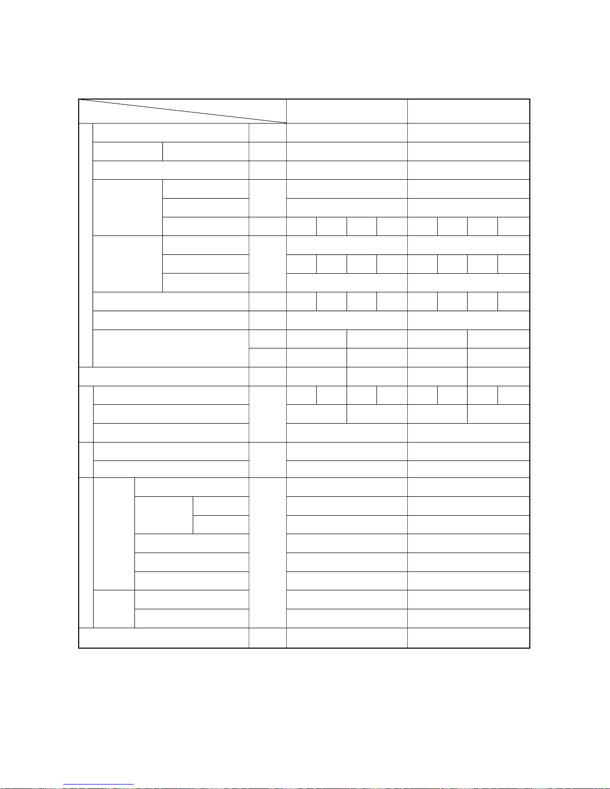
[4] Standard Operation Data
1 Cooling operation
Heat source unit
Items
PQRY-P200 PQRY-P250
Indoor
Quantity
Quantity in operation
Model
Main pipe
Branch pipe
Total piping length
380-415V/50Hz • 60Hz 380-415V/50Hz • 60Hz
27.0/19.0 27.0/19.0
30 30
4
4
4
4
63 63 50 25 125 40 63 25
55
55555555
25 25
Hi Hi Hi Hi Hi Hi Hi Hi
11.4 12.2
330 460 430 300 410 330 460 300
2000 240 2000 260
180 330
2.20/0.52 2.15/0.50
2.09/2.09 2.04/2.04
101 99.0
77
10 10
12 12
4.9 4.3
70 78
26 30
15 15
0.23 0.23
380 415 380 415
270/77 270/77 340/95 340/95
14.0 12.8 18.8 17.2
Indoor unit fan notch
Refrigerant volume
Compressor volts / Frequency
Heat source unit
Indoor unit
BC controller (1, 3)
Oil return
High pressure/Low pressure
BC controller liquid/Intermediate
Pressure
V/Hz
DB/WB
°C
Q’ty
–
m
–
kg
V
V/Hz
A
Pulse
MPa
˚C
Condition
Sectional temperature
LEV opening
Discharge (TH1)
Accumulator
Suction (Comp)
CS circuit (TH2)
Shell bottom (Comp)
LEV inlet
Heat exchanger outlet
Inlet
Outlet
Heat
source
unit
Indoor
unit
αOC
Circulated water temp. (Intet)
Power source
Ambient temp.
Indoor unit
Piping
–27–
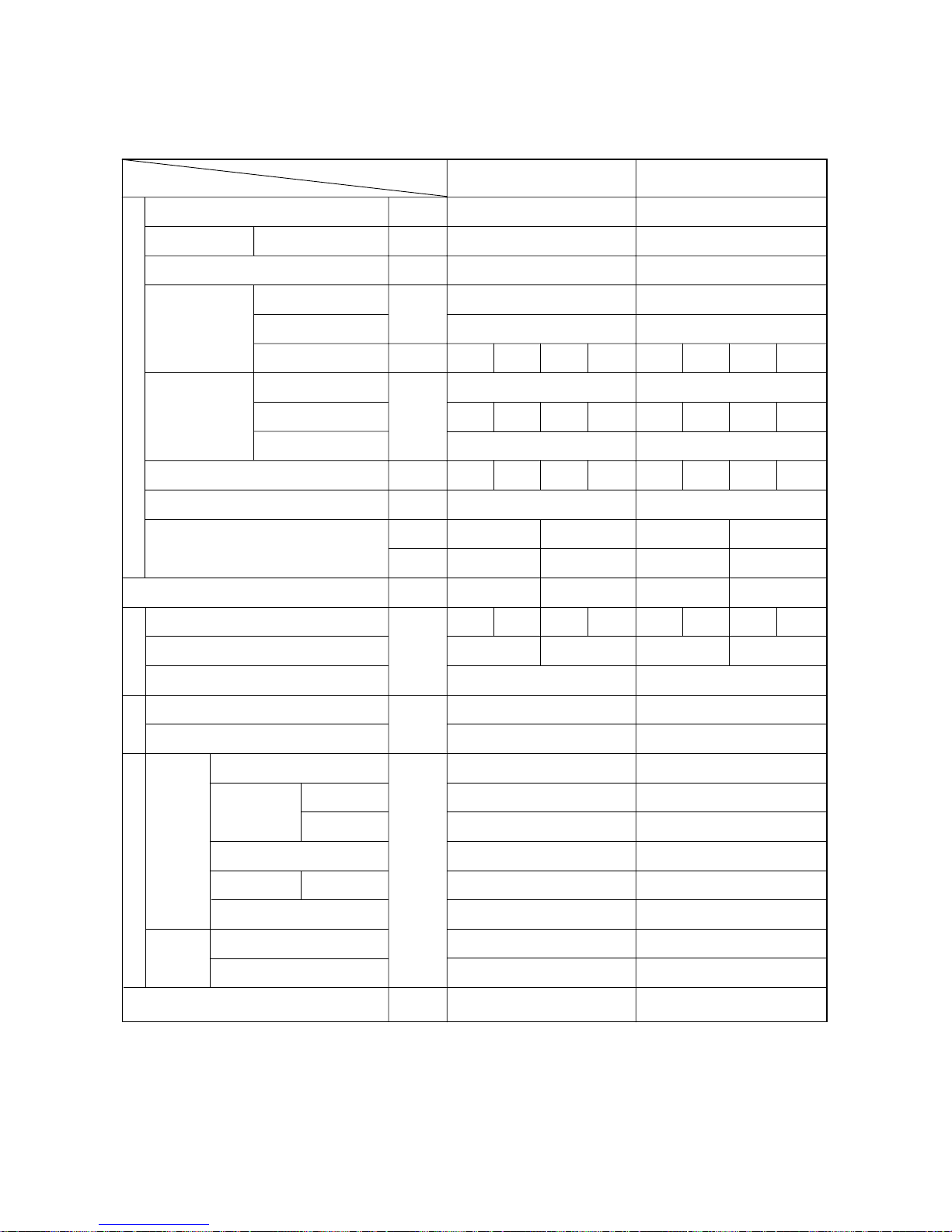
2 Heating operation
Heat source unit
Items
PQRY-P200 PQRY-P250
Indoor
Quantity
Quantity in operation
Model
Main pipe
Branch pipe
Total piping length
380-415V/50Hz • 60Hz 380-415V/50Hz • 60Hz
20.0/– 20.0/–
20 20
4
4
63 63 50 25 125 40 63 25
5
4
4
5
55555555
25 25
Hi Hi Hi Hi Hi Hi Hi Hi
11.4 12.2
600 950 750 400 750 600 950 400
60 600 60 850
115 115
2.20/0.56 2.20/0.54
2.10/1.80 2.10/1.80
75 79
–1 –1
–4 –2
–1 –1
75
55 60
38 40
80 85
0.28 0.28
380 415 380 415
250/75 250/75 330/93 330/93
13.1 12.0 16.1 14.8
Indoor unit fan notch
Refrigerant volume
Compressor volts/Frequency
Heat source unit total current
Indoor unit
BC controller (1, 3)
Oil return
High pressure/Low pressure
BC controller liquid/Intermediate
Pressure
V/Hz
DB/WB
°C
Q’ty
–
m
–
kg
V
V/Hz
A
Pulse
MPa
˚C
Condition
Sectional temperature LEV opening
Discharge (TH1)
Accumulator
Suction (Comp)
CS circuit
Shell bottom (Comp)
LEV inlet
Heat exchanger outlet
Inlet
Outlet
(TH2)
Heat
source
unit
Indoor
unit
αOC
Power source
Ambient temp.
C
Indoor unit
Piping
Circulated water temp.
–28–
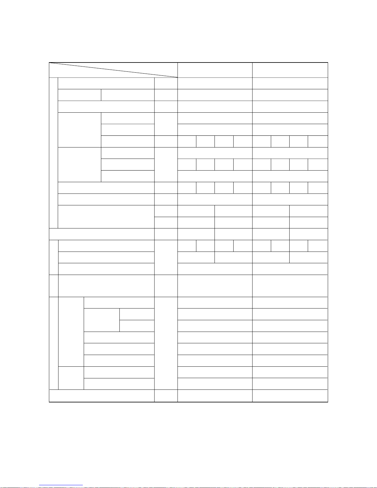
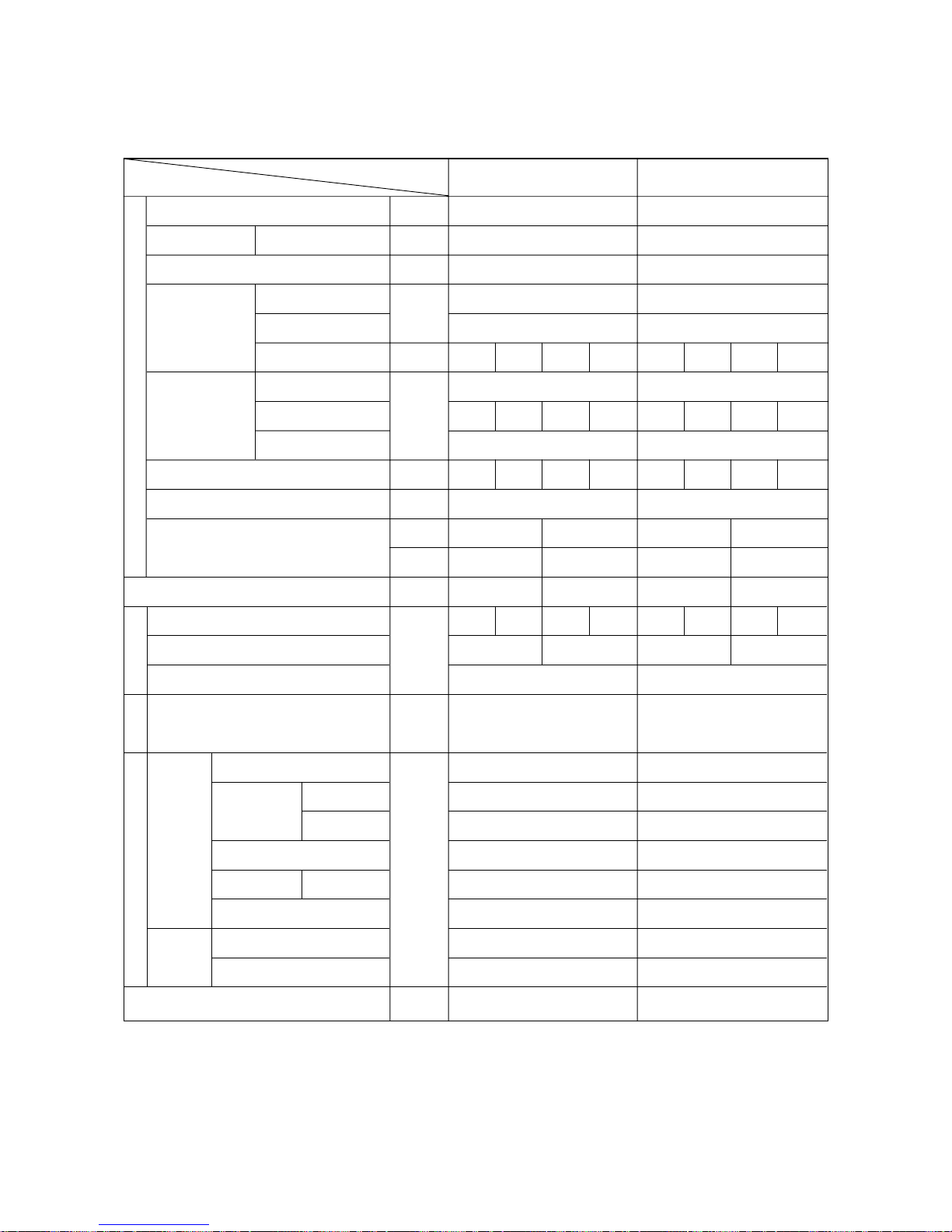
1 Cooling operation
Heat source unit
Items
PQHY-P200 PQHY-P250
Indoor
Quantity
Quantity in operation
Model
Main pipe
Branch pipe
Total piping length
380-415V/50Hz • 60Hz 380-415V/50Hz • 60Hz
27.0/19.0 27.0/19.0
30 30
4
4
4
4
63 63 50 25 125 40 63 25
55
55555555
25 25
Hi Hi Hi Hi Hi Hi Hi Hi
11.4 12.2
330 460 430 300 410 330 460 300
2000 240 2000 260
180 330
2.20/0.52 2.15/0.50
101 99.0
77
10 10
12 12
4.9 4.3
70 78
26 30
15 15
0.23 0.23
380 415 380 415
270/77 270/77 340/95 340/95
14.0 12.8 18.8 17.2
Indoor unit fan notch
Refrigerant volume
Compressor volts / Frequency
Heat source unit
Indoor unit
BC controller (1, 3)
Oil return
High pressure/Low pressure
Pressure
V/Hz
DB/WB
°C
Q’ty
–
m
–
kg
V
V/Hz
A
Pulse
MPa
˚C
Condition
Sectional temperature
LEV opening
Discharge (TH1)
Accumulator
Suction (Comp)
CS circuit (TH2)
Shell bottom (Comp)
LEV inlet
Heat exchanger outlet
Inlet
Outlet
Heat
source
unit
Indoor
unit
αOC
Circulated water temp. (Intet)
Power source
Ambient temp.
Indoor unit
Piping
–29–
2 Heating operation
Heat source unit
Items
PQHY-P200
PQHY-P250
Indoor
Quantity
Quantity in operation
Model
Main pipe
Branch pipe
Total piping length
380-415V/50Hz • 60Hz 380-415V/50Hz • 60Hz
20.0/– 20.0/–
20 20
4
4
63 63 50 25 125 40 63 25
5
4
4
5
55555555
25 25
Hi Hi Hi Hi Hi Hi Hi Hi
11.4 12.2
600 950 750 400 750 600 950 400
60 600 60 850
115 115
2.20/0.56 2.20/0.54
75 79
–1 –1
–4 –2
–1 –1
75
55 60
38 40
80 85
0.28 0.28
380 415 380 415
250/75 250/75 330/93 330/93
13.1 12.0 16.1 14.8
Indoor unit fan notch
Refrigerant volume
Compressor volts/Frequency
Heat source unit total current
Indoor unit
BC controller (1, 3)
Oil return
High pressure/Low pressure
Pressure
V/Hz
DB/WB
°C
Q’ty
–
m
–
kg
V
V/Hz
A
Pulse
MPa
˚C
Condition
Sectional temperature LEV opening
Discharge (TH1)
Accumulator
Suction (Comp)
CS circuit
Shell bottom (Comp)
LEV inlet
Heat exchanger outlet
Inlet
Outlet
(TH2)
Heat
source
unit
Indoor
unit
αOC
Power source
Ambient temp.
C
Indoor unit
Piping
Circulated water temp.
 Loading...