

Mitsubishi PUHY-250YMF-B, PUY-200YMF-B, PUHY-P200YMF-B, PUHY-P250YMF-B, PUY-250YMF-B Service Handbook
...Page 1

AIR CONDITIONERS CITY MULTI
Models PUHY-200YMF-B, 250YMF-B
PUHY-P200YMF-B, P250YMF-B
PUY-200YMF-B, 250YMF-B
PURY-200YMF-B, 250YMF-B
PURY-P200YMF-B, P250YMF-B
CMB-P104, P105, P106, P108, P1010V-D
CMB-P104, P105, P106, P108, P1010, P1013, P1016V-E
Service Handbook
Service Handbook PUHY, PUY, PURY-200·250YMF-B/PUHY, PURY-P200·P250YMF-B/CMB-P-V-D, CMB-P-V-E
Page 2

Page 3
–1–
11
11
1 PRECAUTIONS FOR DEVICES THAT USE R407C REFRIGERANT
Caution
Do not use the existing refrigerant piping.
• The old refrigerant and refrigerator oil in the existing
piping contains a large amount of chlorine which may
cause the refrigerator oil of the new unit to deteriorate.
Use refrigerant piping made of C1220 (CU-DHP) phosphorus deoxidized copper as specified in the *JIS
H3300 “Copper and copper alloy seamless pipes and
tubes”. In addition, be sure that the inner and outer
surfaces of the pipes are clean and free of hazardous
sulphur, oxides, dust/dirt, shaving particles, oils,
moisture, or any other contaminant.
• Contaminants on the inside of the refrigerant piping
may cause the refrigerant residual oil to deteriorate.
*JIS: Japanese Industrial Standard
Store the piping to be used during installation indoors
and keep both ends of the piping sealed until just
before brazing. (Store elbows and other joints in a
plastic bag.)
• If dust, dirt, or water enters the refrigerant cycle,
deterioration of the oil and compressor trouble may
result.
Use ester oil, ether oil or alkylbenzene (small
amount) as the refrigerator oil to coat flares and
flange connections.
• The refrigerator oil will degrade if it is mixed with a
large amount of mineral oil.
Use liquid refrigerant to seal the system.
• If gas refrigerant is used to seal the system, the composition of the refrigerant in the cylinder will change
and performance may drop.
Do not use a refrigerant other than R407C.
• If another refrigerant (R22, etc.) is used, the chlorine
in the refrigerant may cause the refrigerator oil to deteriorate.
Use a vacuum pump with a reverse flow check valve.
• The vacuum pump oil may flow back into the refrigerant cycle and cause the refrigerator oil to deteriorate.
Do not use the following tools that have been used
with conventional refrigerants.
(Gauge manifold, charge hose, gas leak detector, reverse flow check valve, refrigerant charge base,
vacuum gauge, refrigerant recovery equipment)
• If the conventional refrigerant and refrigerator oil are
mixed in the R407C, the refrigerant may deteriorated.
• If water is mixed in the R407C, the refrigerator oil
may deteriorate.
• Since R407C does not contain any chlorine, gas
leak detectors for conventional refrigerants will not
react to it.
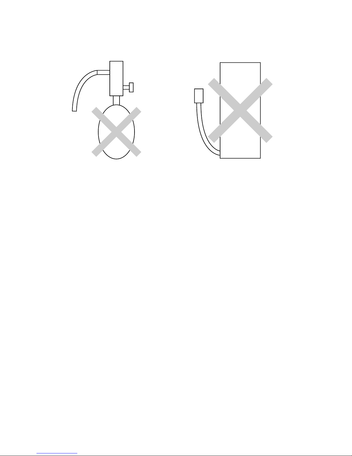
Do not use a charging cylinder.
• Using a charging cylinder may cause the refrigerant
to deteriorate.
Be especially careful when managing the tools.
• If dust, dirt, or water gets in the refrigerant cycle, the
refrigerant may deteriorate.
If the refrigerant leaks, recover the refrigerant in the
refrigerant cycle, then recharge the cycle with the
specified amount of the liquid refrigerant indicated
on the air conditioner.
• Since R407C is a nonazeotropic refrigerant, if additionally charged when the refrigerant leaked, the composition of the refrigerant in the refrigerant cycle will
change and result in a drop in performance or abnormal stopping.
Page 4
–2–
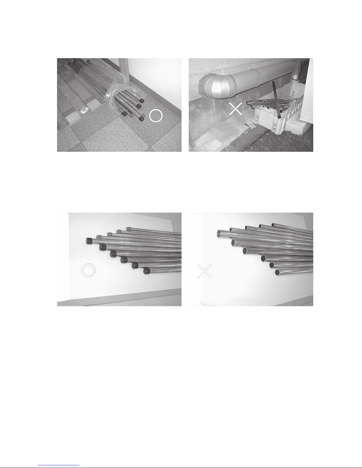
[1] Storage of Piping Material
(1) Storage location
Store the pipes to be used indoors. (Warehouse at site or owner’s warehouse)
Storing them outdoors may cause dirt, waste, or water to infiltrate.
(2) Pipe sealing before storage
Both ends of the pipes should be sealed until immediately before brazing.
Wrap elbows and T’s in plastic bags for storage.
* The new refrigerator oil is 10 times more hygroscopic than the conventional refrigerator oil (such as Suniso). Water
infiltration in the refrigerant circuit may deteriorate the oil or cause a compressor failure. Piping materials must be
stored with more care than with the conventional refrigerant pipes.
Page 5
–3–
[2] Piping Machining
Use ester oil, ether oil or alkylbenzene (small amount) as the refrigerator oil to coat flares and flange connections.
Use only the necessary minimum quantity of oil !
Reason :
1. The refrigerator oil used for the equipment is highly hygroscopic and may introduce water inside.
Notes :
• Introducing a great quantity of mineral oil into the refrigerant circuit may also cause a compressor failure.
• Do not use oils other than ester oil, ether oil or alkylbenzene.
Page 6
–4–
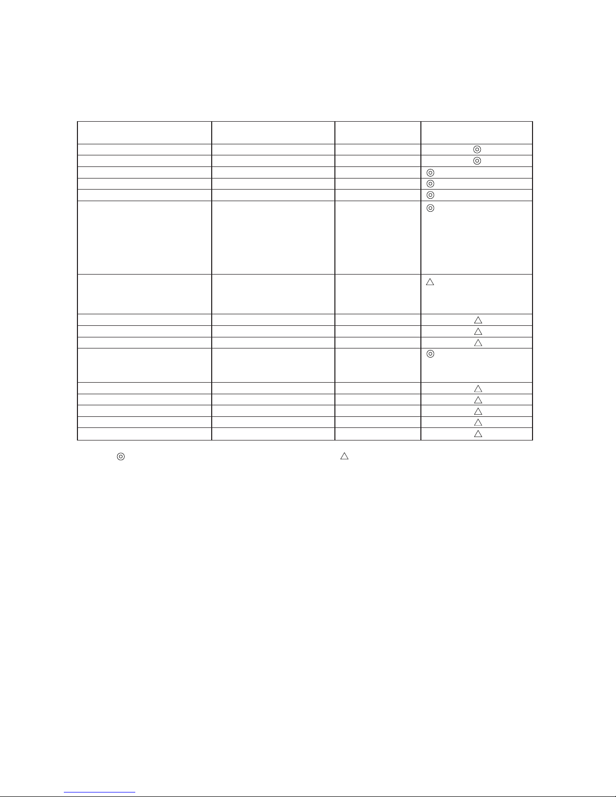
[3] Necessary Apparatus and Materials and Notes on Their Handling
The following tools should be marked as dedicated tools for R407C.
<<Comparison of apparatus and materials used for R407C and for R22>>
Apparatus Used Use R22 R407C
Gauge manifold Evacuating, refrigerant filling Current product
Charging hose Operation check Current product
Charging cylinder Refrigerant charging Current product Do not use.
Gas leakage detector Gas leakage check Current product Shared with R134a
Refrigerant collector Refrigerant collection R22 For R407C use only
Refrigerant cylinder Refrigerant filling R22
Vacuum pump Vacuum drying Current product
Vacuum pump with a check valve Current product
Flare tool Flaring of pipes Current product
Bender Bending of pipes Current product
Application oil Applied to flared parts Current product
Torque wrench Tightening of flare nuts Current product
Pipe cutter Cutting of pipes Current product
Welder and nitrogen cylinder Welding of pipes Current product
Refrigerant charging meter Refrigerant charging Current product
Vacuum gauge Checking the vacuum degree Current product
Symbols :
To be used for R407C only. Can also be used for conventional refrigerants.
Tools for R407C must be handled with more care than those for conventional refrigerants. They must not come into contact
with any water or dirt.
Identification of dedicated use for R407C
: Record refrigerant
name and put brown
belt on upper part of
cylinder.
Can be used by
attaching an adapter
with a check valve.
Ester oil or Ether oil or
Alkybenzene (Small
amount)
Page 7
–5–
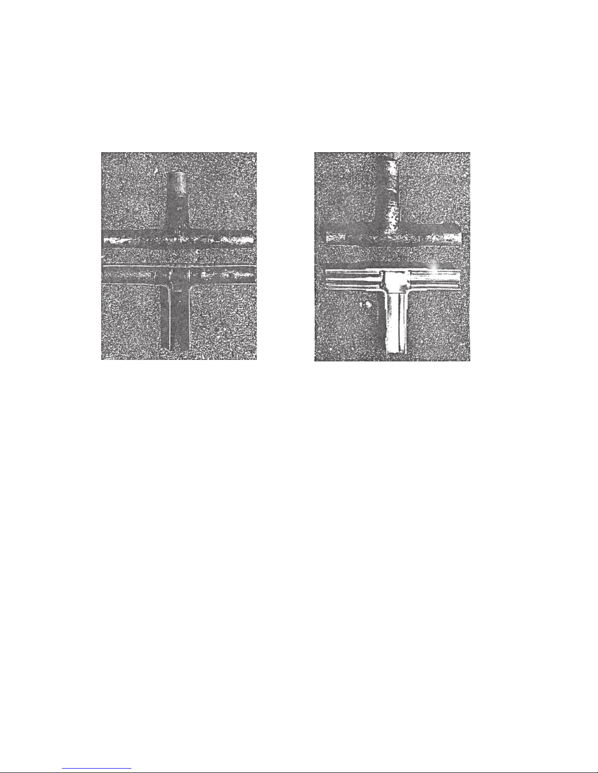
[4] Brazing
No changes from the conventional method, but special care is required so that foreign matter (ie. oxide scale, water, dirt,
etc.) does not enter the refrigerant circuit.
Example : Inner state of brazed section
When non-oxide brazing was not used When non-oxide brazing was used
Items to be strictly observed :
1. Do not conduct refrigerant piping work outdoors on a rainy day.
2. Apply non-oxide brazing.
3. Use a brazing material (Bcup-3) which requires no flux when brazing between copper pipes or between a copper pipe
and copper coupling.
4. If installed refrigerant pipes are not immediately connected to the equipment, then braze and seal both ends of them.
Reasons :
1. The new refrigerant oil is 10 times more hygroscopic than the conventional oil. The probability of a machine failure if
water infiltrates is higher than with conventional refrigerant oil.
2. A flux generally contains chlorine. A residual flux in the refrigerant circuit may generate sludge.
Note :
• Commercially available antioxidants may have adverse effects on the equipment due to its residue, etc. When
applying non-oxide brazing, use nitrogen.
Page 8
–6–
[5] Airtightness Test
No changes from the conventional method. Note that a refrigerant leakage detector for R22 cannot detect R407C
leakage.
Halide torch R22 leakage detector
Items to be strictly observed :
1. Pressurize the equipment with nitrogen up to the design pressure and then judge the equipment’s airtightness, taking
temperature variations into account.
2. When investigating leakage locations using a refrigerant, be sure to use R407C.
3. Ensure that R407C is in a liquid state when charging.
Reasons :
1. Use of oxygen as the pressurized gas may cause an explosion.
2. Charging with R407C gas will lead the composition of the remaining refrigerant in the cylinder to change and this
refrigerant can then not be used.
Note :
• A leakage detector for R407C is sold commercially and it should be purchased.
[6] Vacuuming
1. Vacuum pump with check valve
A vacuum pump with a check valve is required to prevent the vacuum pump oil from flowing back into the refrigerant
circuit when the vacuum pump power is turned off (power failure).
It is also possible to attach a check valve to the actual vacuum pump afterwards.
2. Standard degree of vacuum for the vacuum pump
Use a pump which reaches 0.5 Torr (500 MICRON) or below after 5 minutes of operation.
In addition, be sure to use a vacuum pump that has been properly maintained and oiled using the specified oil. If the
vacuum pump is not properly maintained, the degree of vacuum may be too low.
3. Required accuracy of the vacuum gauge
Use a vacuum gauge that can measure up to 5 Torr. Do not use a general gauge manifold since it cannot measure a
vacuum of 5 Torr.
4. Evacuating time
• Evacuate the equipment for 1 hour after –755 mmHg (5 Torr) has been reached.
• After envacuating, leave the equipment for 1 hour and make sure the that vacuum is not lost.
5. Operating procedure when the vacuum pump is stopped
In order to prevent a backflow of the vacuum pump oil, open the relief valve on the vacuum pump side or loosen the
charge hose to drawn in air before stopping operation.
The same operating procedure should be used when using a vacuum pump with a check valve.
Page 9
–7–
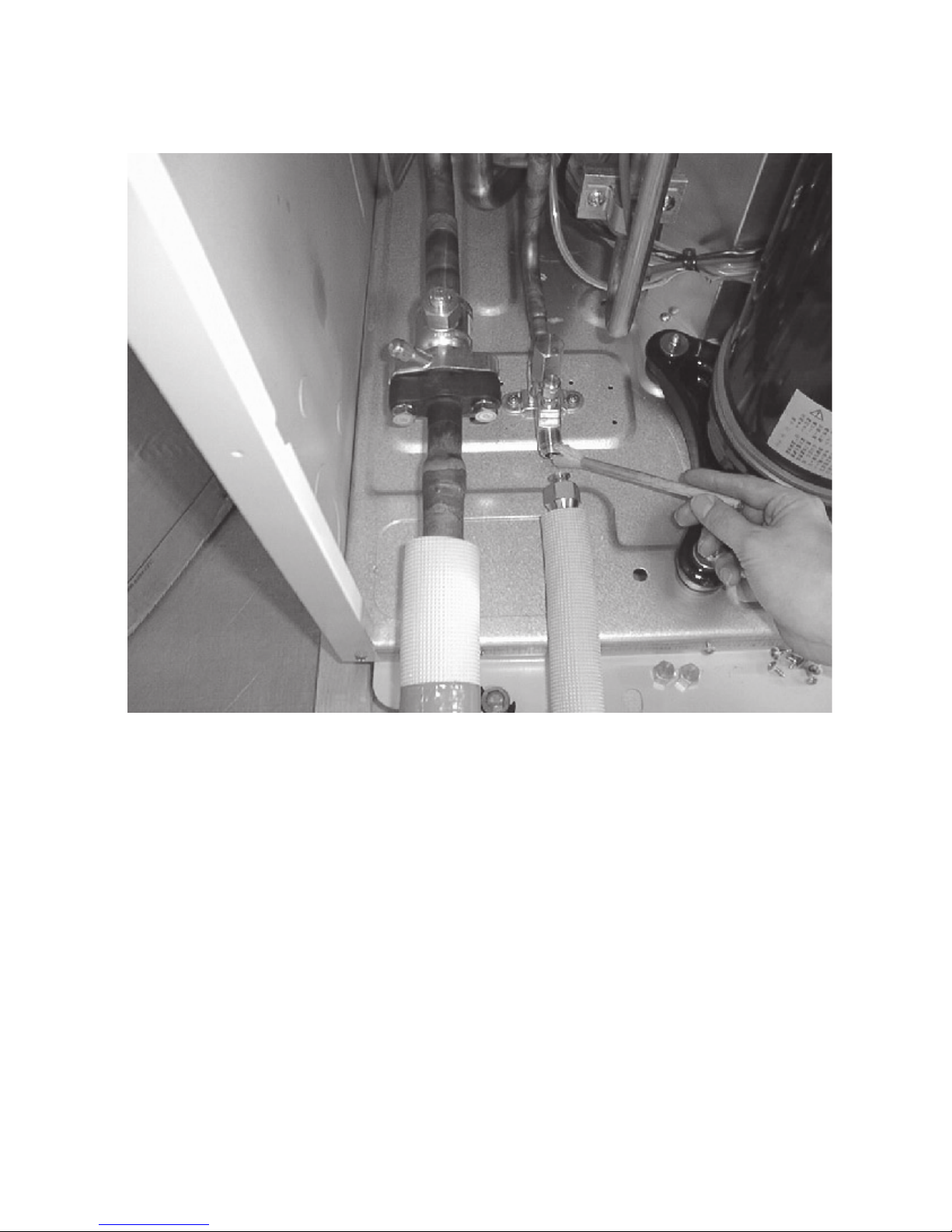
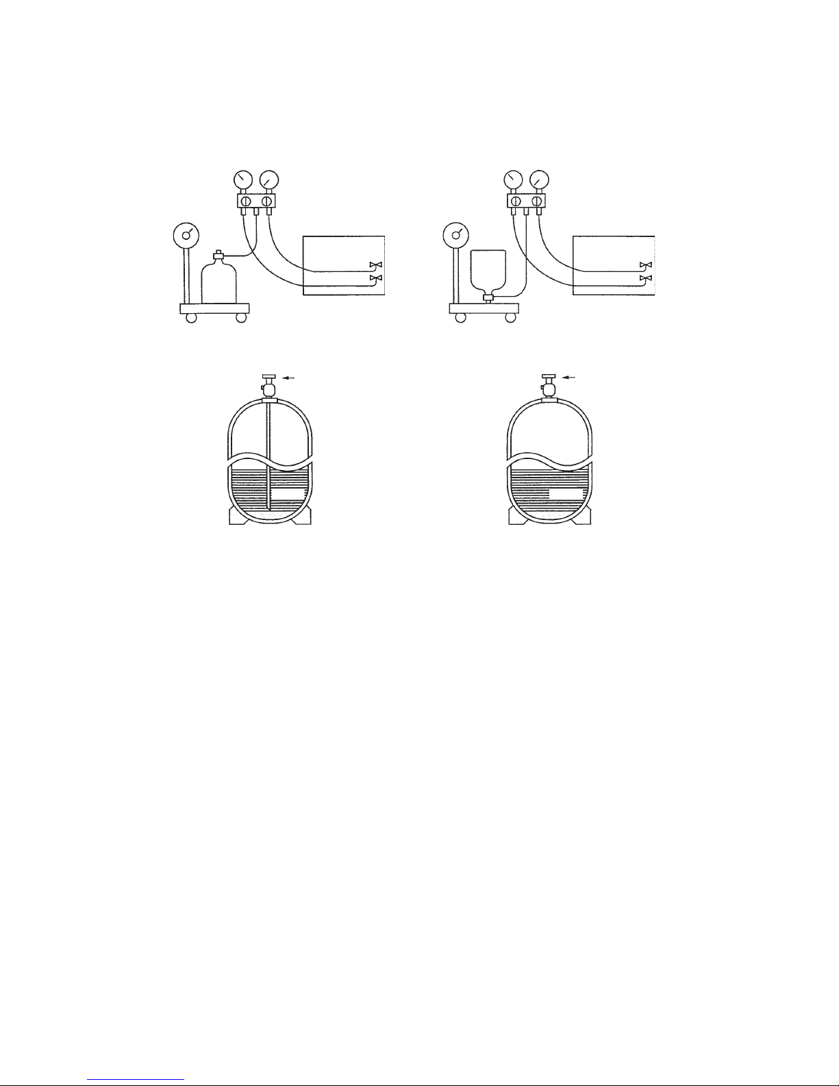
[7] Charging of Refrigerant
R407C must be in a liquid state when charging, because it is a non-azeotropic refrigerant.
For a cylinder with a syphon attached For a cylinder without a syphon attached
Cylinder color identification R407C-Gray Charged with liquid refrigerant
R410A-Pink
Reasons :
1. R407C is a mixture of 3 refrigerants, each with a different evaporation temperature. Therefore, if the equipment is
charged with R407C gas, then the refrigerant whose evaporation temperature is closest to the outside temperature is
charged first while the rest of refrigerants remain in the cylinder.
Note :
• In the case of a cylinder with a syphon, liquid R407C is charged without turning the cylinder up side down. Check the
type of cylinder before charging.
[8] Dryer
1. Replace the dryer when the refrigerant circuit is opened (Ex. Change the compressor, full gas leakage). Be sure to
replace the dryer with a CITY MULTI Series Y (For use with R407C).
If any other product is used, the unit will be damaged.
2. Opening the refrigerant circuit after changing to a new dryer is less than 1 hour. The replacement of the dryer should
be the last operation performed.
Cylin-
der
Cylin-
der
Val ve
Val ve
Liquid
Liquid
Page 10
–8–
22
22
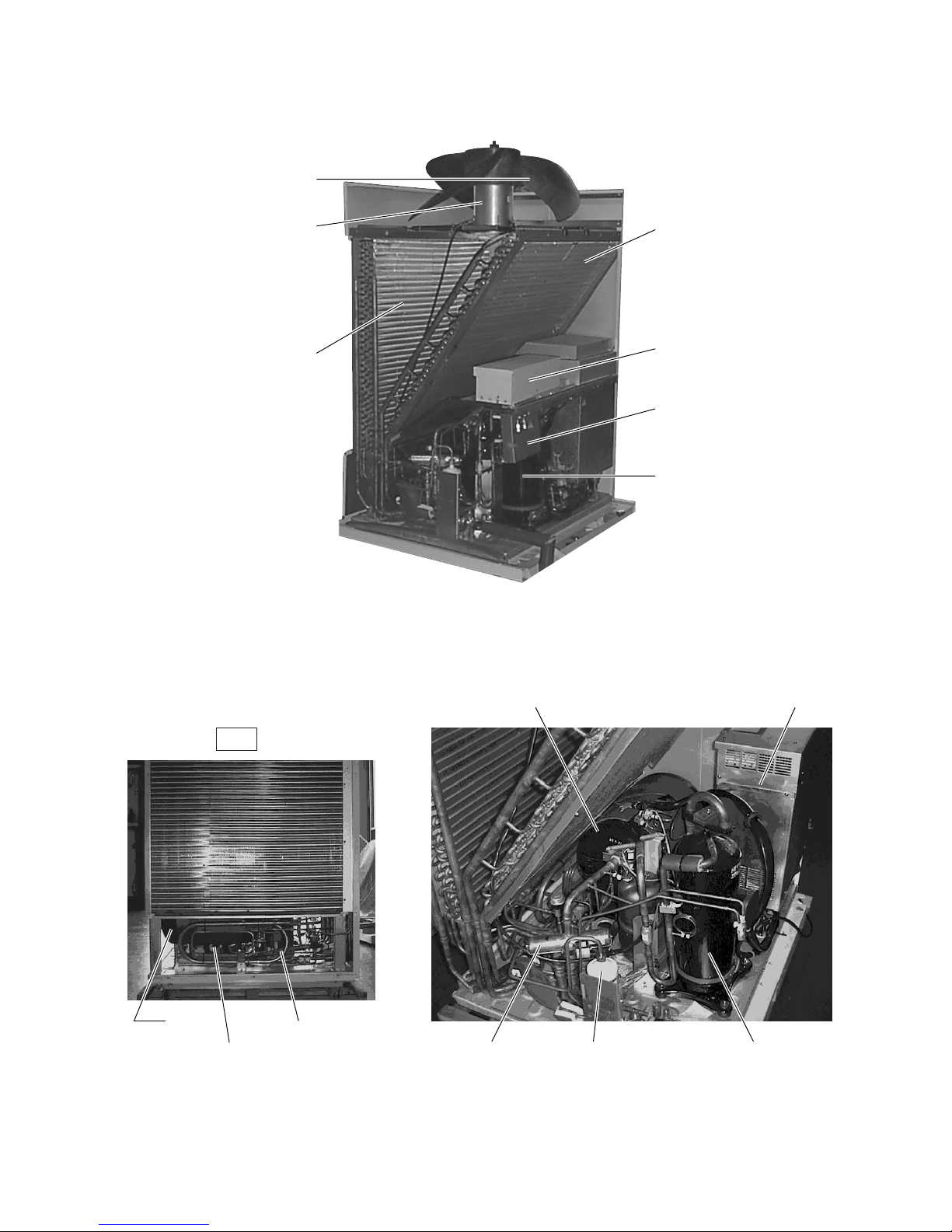
2 COMPONENT OF EQUIPMENT
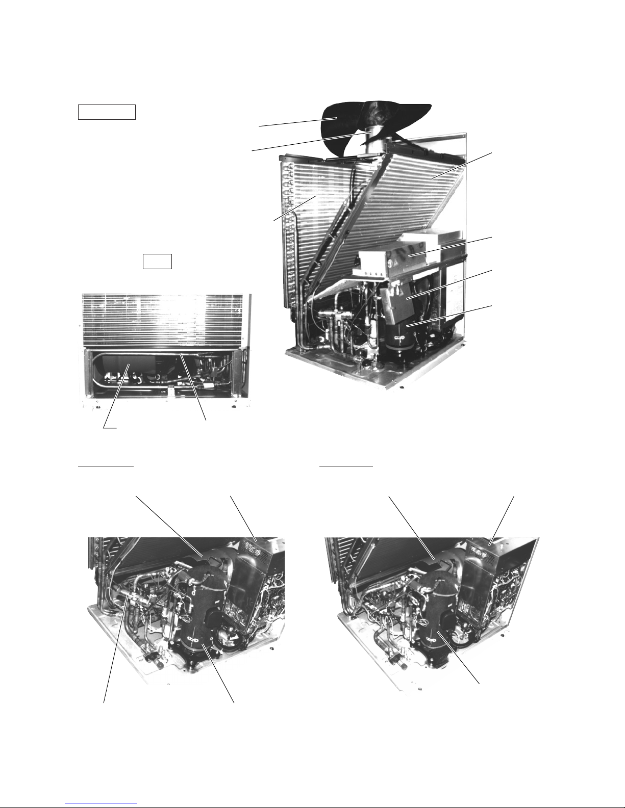
[1] Appearance of Components
Outdoor unit
• PU(H)Y-200, 250YMF-B
Rear
PUHY-YMF-B PUY-YMF-B
Propeller fan
Fan motor
Heat exchanger
(front)
Noise
filter
Heat exchanger
(rear)
Terminal
Box
Compressor
Accumulator
SCC
Accumulator Control Box Accumulator Control Box
4-way valve Compressor
Compressor
Page 11
–9–
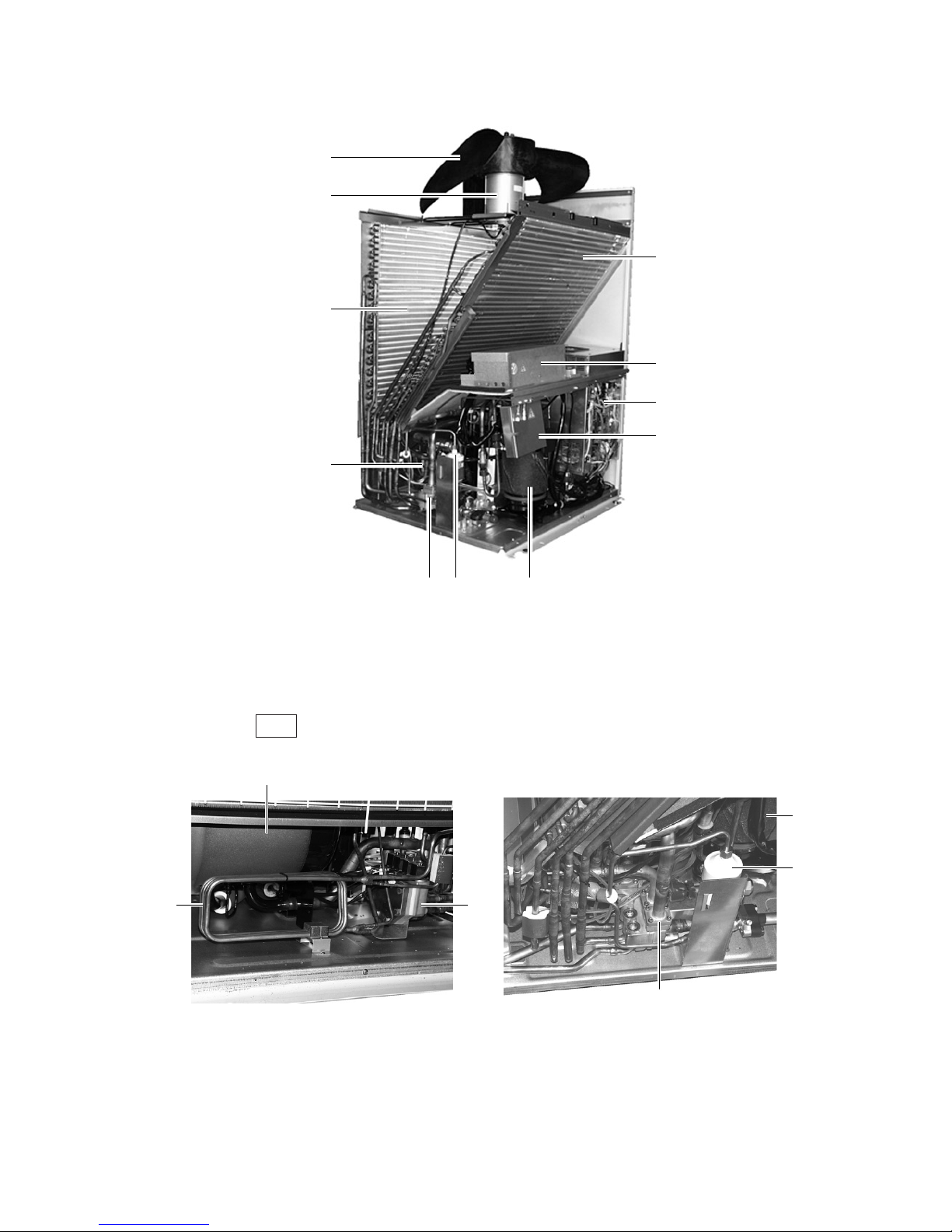
• PUHY-P200·250YMF-B
Propeller fan
Fan motor
Heat exchanger (front)
Heat exchanger (rear)
Noise filter
Terminal Box
Compressor
Drier
Accumulator Control Box
4-way valve Compressor
SCC
Accumulator
Rear
Heat exchanger
of CS circuit
Page 12
–10–
• PURY-P200·250YMF-B
Propeller fan
Solenoid Valves
(SV) Block
Fan motor
Heat exchanger
(rear)
Accumulator
Compressor
Terminal Box
Check Valves
(CV) Block
Drier
CV block
Rear
SV
block
Heat
exchanger
of CS circuit
Compressor
Drier
Heat exchanger
(front)
Noise filter
Control Box
Page 13
–11–
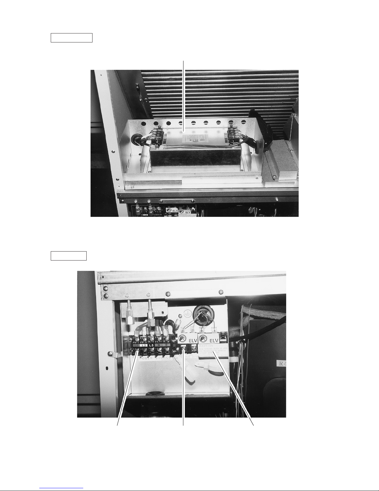
Noise Filter Box
Terminal Box
Noise filter
Terminal block TB3
Transmission
Terminal block TB1
Power source
Terminal block TB7
Transmission (Centralized control)
Page 14
–12–
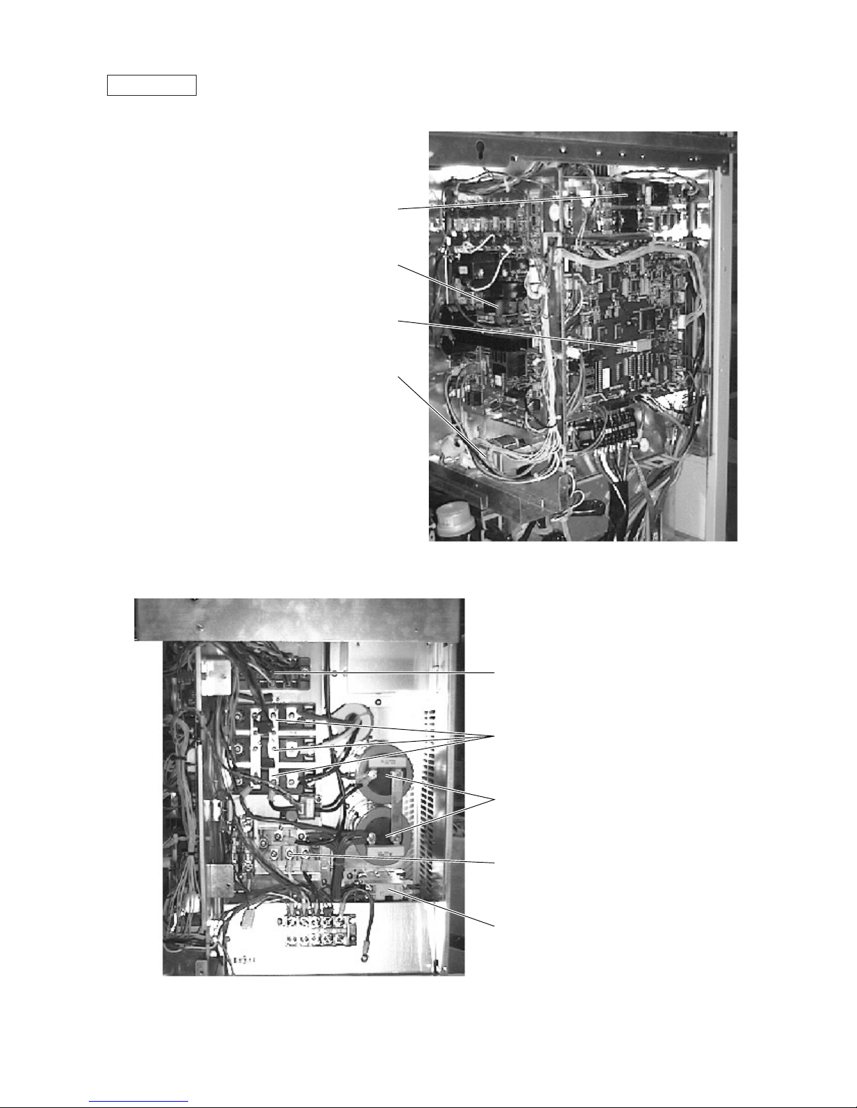
Controller Box
FANCON board
Choke coil (L2)
INV board
MAIN board
Thyristor module (SCRM)
Diode stack (DS)
Transistor module (TRM)
Capacitor (C2, C3)
(Smoothing capacitor)
Magnetic contactor (52C)
Page 15
–13–
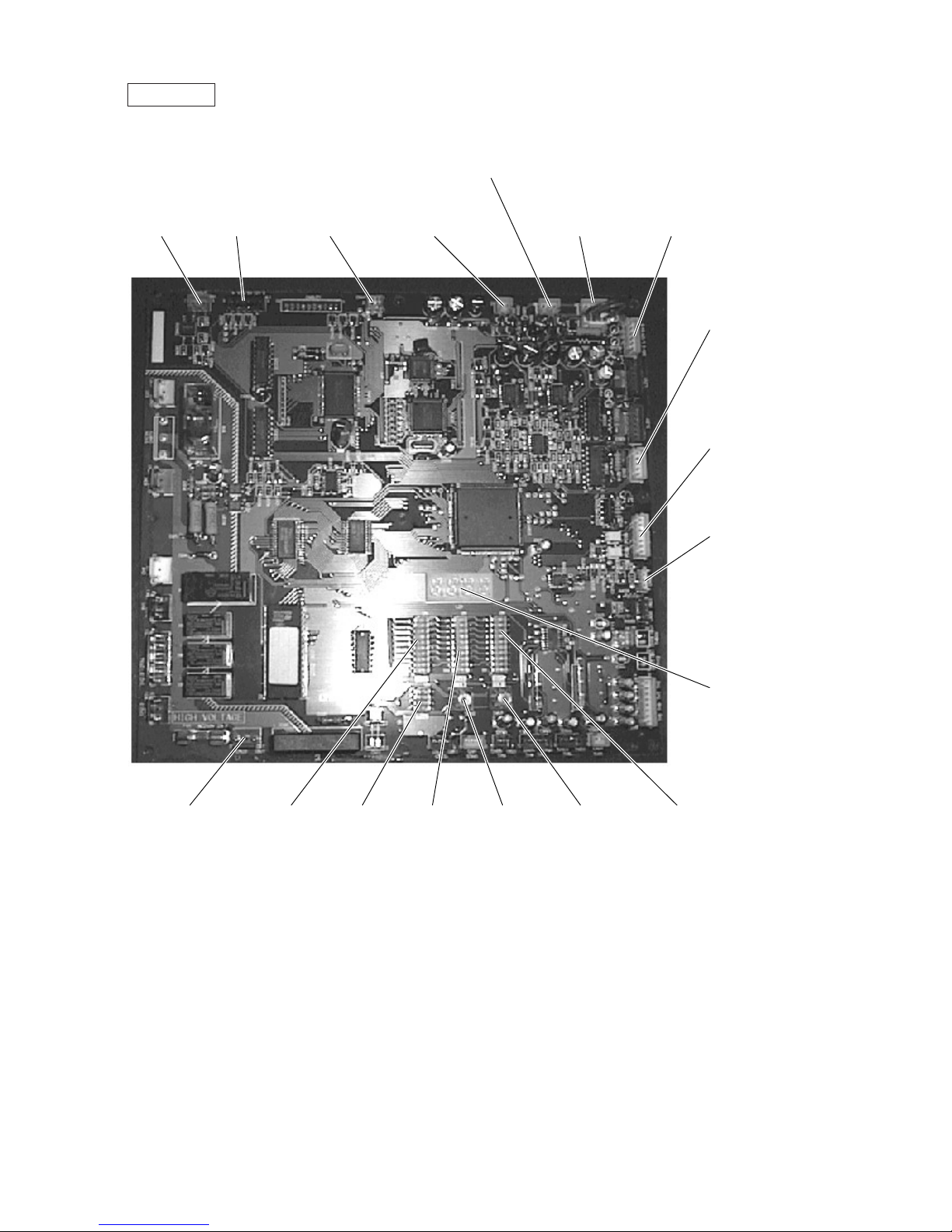
MAIN board
• PUHY
CN51
Indication distance
3-4 Compressor
ON/OFF
3-5 Trouble
LD1
Service LED
CNRS3
Serial transmission to
INV board
CN3D
Cooling/Heating auto
changeover
SW1
CNTR CNFC1
CNVCC4
Power source for
control
CNVCC3
Power source for
control
1-2 30V, 1-3 30V
4-6 12V, 5-6 5V
CNS1
M-NET transmision
CNS2
M-NET transmission
(Centralized control)
CN40
M-NET transmission
power supply
CN20
Power supply
3 L1
1 N
SW3 SW4 SW2 SWU2 SWU1
Page 16

–14–
MAIN board
• PURY
CN51
Indication distance
3-4 Compressor
ON/OFF
3-5 Trouble
LD1
Service LED
CNRS3
Serial transmission to
INV board
CNTR CNFC1
CNVCC4
Power source for
control
CNVCC3
Power source for
control
1-2 30V, 1-3 30V
4-6 12V, 5-6 5V
CNS2
M-NET transmission
(Centralized control)
CNS1
M-NET
transmission
CN20
Power supply
3 L1
1 N
SW3 SW4 SW2
CN40
M-NET transmission
power supply
SWU2 SWU1 SW1
Page 17
–15–
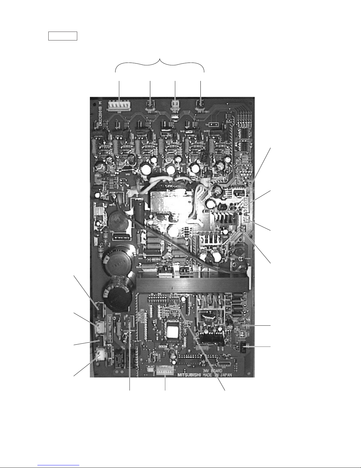
INV board
CN3 CN2-1 CN2-2 CN2-3
Output to transistor module (INVERTER)
CNL2
Choke coil
CNTH
CN30V
CNVCC1
Power supply
1-2 30V, 1-3 30V
4-6 12V, 5-6 5V
CNVCC2
Power supply (5V)
CNCT
CNVDC
1-4
DC-560V
CNAC2
Powe r
source
1 L2
3 N
CN52C
Control for
52C
CNFAN
Control
for MF1
CNR CNRS2
Serial transmission
to MAIN board
SW1
Page 18
–16–
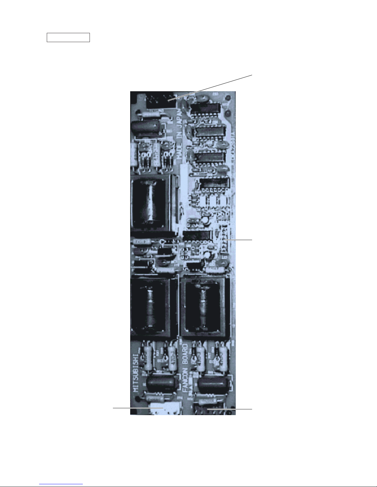
FANCON board
CNFC2
CNU
CNW
CNV
Page 19
–17–
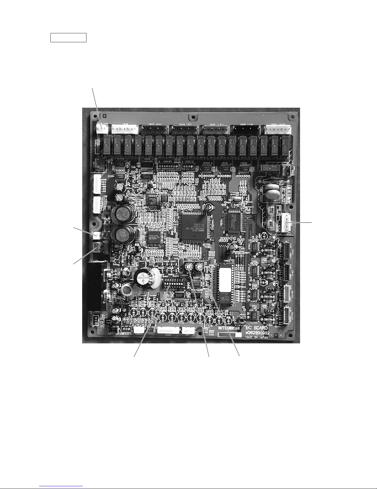
BC controller
CNTR
CN02
M-NET
transmission
CN03
CN12
Power
supply
1 EARTH
3 N
5 L
SW4 SW2 SW1
Page 20
–18–
TH1
TH6
TH7
TH8
TH5
TH3
TH4
TH2
Indoor units
CJ1
O/S
63HS
CJ1
Comp
HEX2
HEX1
SCC
LEV1
ST7
BV2
ST2
BV1
ST1
CJ2
CV1
ST6
SV1
CP1
SV2ST5
CP2
CP4
ST3
ST4
SLEV
SA
MA
CP3
63H
6-2
27
8
40 6
CH
93 80
*Operation data of PUHY-200YMF-B
Standard operation data are shown for cooling
in the C column and heating in the H column.
Units for each value are : ˚C for TH1
˜
TH8
: kg/cm
2
G (MPa) for HPS
*
6-1
30 36
20.3
(1.99)
17.5
(1.72)
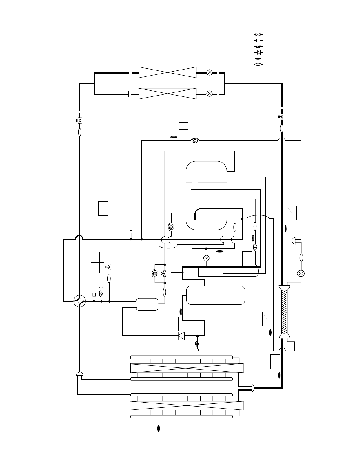
[2] Refrigerant Circuit Diagram and Thermal Sensor
1PUHY-200YMF-B, 250YMF-B
: Solenoid valve
: Orifice
: Capillary
: Check valve
: Thermal sensor
: Strainer
SP : Service port
ACC : Accumulator
Page 21
–19–
TH1
TH6
TH7
TH8
TH5
TH3
TH4
TH2
Indoor units
CJ1
O/S
63HS
CJ1
Comp
HEX2
HEX1
SCC
LEV1
ST7
BV2
ST2
BV1
ST1
CJ2
CV1
ST6
SV1
CP1
SV2ST5
CP2
CP4
ST3
ST4
SLEV
SA
MA
CP3
63H
6
27
8
40
C
93
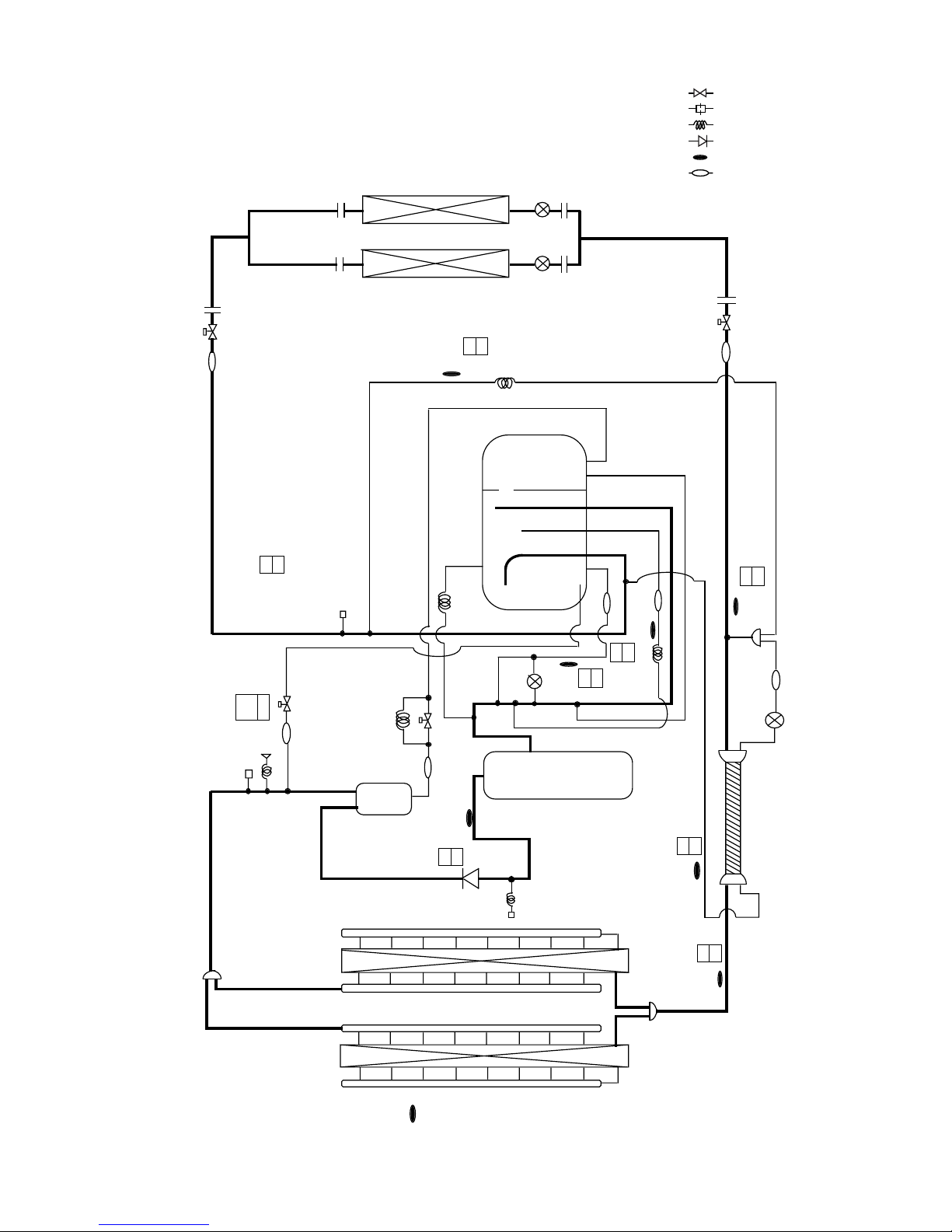
*Operation data of PUY-200YMF-B
Standard operation data are shown for cooling
in the C.
Units for each value are : ˚C for TH1
˜
TH8
: kg/cm
2
G (MPa) for HPS
*
6
30
20.3
(1.99)
: Solenoid valve
: Orifice
: Capillary
: Check valve
: Thermal sensor
: Strainer
SP : Service port
ACC : Accumulator
2PUY-200YMF-B, 250YMF-B
Page 22

–20–
SCC
11 0
85 70
21.9
(2.15)
21.4
(2.10)
96 78
111 87
34 36
3.93 3.67
19 -3
0.23 0.28
-1 -3
42 -1
CH
8
27
85 0
LEV1
HEX f HEX b
TH6
CS-Circuit
SV2
CP1
CJ1
CJ2
63HS
SV1
ST6
CV1
CP3
O/S
63H
63LS
MA SA
ST8
ST4
TH4
TH3
TH7
ST7
LEV1
ST2
BV2
Indoor units
ST1 BV1
ST3
Comp
Drier
TH9
TH10
CP2
TH2
TH8
TH5
SLEV
ST5
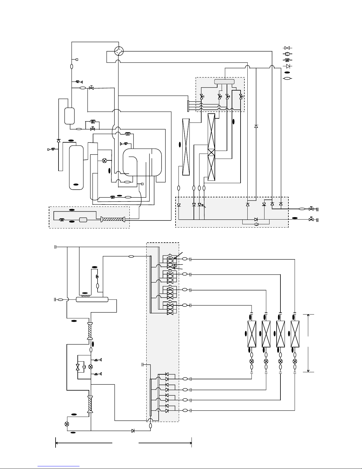
Circulating Configuration : αOC
❈
❈ Operation data of PUHY-P250YMF-B
Standard operation data are shown for cooling in the C column and for heating in
the H column.
TH1~TH5, TH7~TH10 : ˚C
LEV1,SLEV : pulse
HPS, LPS : kg/cm
2
G (MPa)
➂PUHY-P200YMF-B, P250YMF-B
TH1
: Solenoid valve
: Orifice
: Capillary
: Check valve
: Thermal sensor
: Strainer
SP : Service port
ACC : Accumulator
Page 23

–21–
: Solenoid valve
: Orifice
: Capillary
: Check valve
: Thermal sensor
: Strainer
SP : Service port
ACC : Accumulator
➃PURY-200YMF-B, 250YMF-B
TH1
TH5
TH3
TH4
TH23
TH21
TH22
LEV
TH13
PS1
SVC
SVA
SVB
A Block
B Block
C Block
Indoor
units
BC controller
Gas/liquid separator
LEV2
LEV1
SVM
LEV4
LEV3
TH15 TH16
PS3
TH12
O/S
63HS
SP1
Comp
BV2
BV1
ST1
Solenoid Valves
Block
SP2
Check Valves Block
CV1
ST6
SV1
CP1
SV2
ST5
CP2
CP3
ST3
ST4
SLEV
SA
MA
63H
TH6
HEXb
SV6
CV7
SV5
SV3
SV4
HEXf3
HEXf2
HEXf1
CV10
CV3
CV2
CV5
CV4
CV9
CV8
CV6
63LS
TH14
TH11
Distributor
TH7
ACC
CMB-P104V-D
Page 24
–22–
TH1
TH9
Drier
TH5
TH3
TH4
TH2
O/S
63HS
63LS
SP1
Comp
BV2
BV1
ST1
SP2
CS(Composition Sensing) circuit
CV1
ST6
SV1
CP1
SV2
ST5
CP2
CP3
ST3
ST4
SLEV
SA
MA
CP3
63H
TH10
TH6
HEXb
CV7
HEXf3
HEXf2
HEXf1
CV10
CV3
CV2
CV5
CV4
CV9CV8
CV6
TH7
Check Valves Block
Valves Block
ACC
Solenoid Valves
Block
SV6
SV5
SV3
SV4
Distributor
➄PURY-P200YMF-B, P250YMF-B
: Solenoid valve
: Orifice
: Capillary
: Check valve
: Thermal sensor
: Strainer
SP : Service port
ACC : Accumulator
TH23
TH21
TH22
LEV
TH13
SVC
SVA
SVB
Indoor
units
BC controller
CMB-P104V-E
Gas/liquid separator
PS1
LEV1
SVM
PS3
LEV3
TH14
TH12
TH11
TH15
TH16
Page 25
–23–
ON/OFF
–
STAND BY
DEFROST
ERROR CODE
OA UNIT ADDRESS NO.
CENTRALLY CONTROLLED
CLOCK
ON
OFF
˚C
1Hr.
NOT AVAILABLE
˚C
CHECK MODE
FILTER
CHECK
TEST RUN
ON
OFF
CLOCK
FILTER
CHECK
TEST RUN
REMOTE CONTROLLER
NETWORK
PAR-F25MA
TEMP. TIMER SET
INDOOR UNIT
ADDRESS NO.
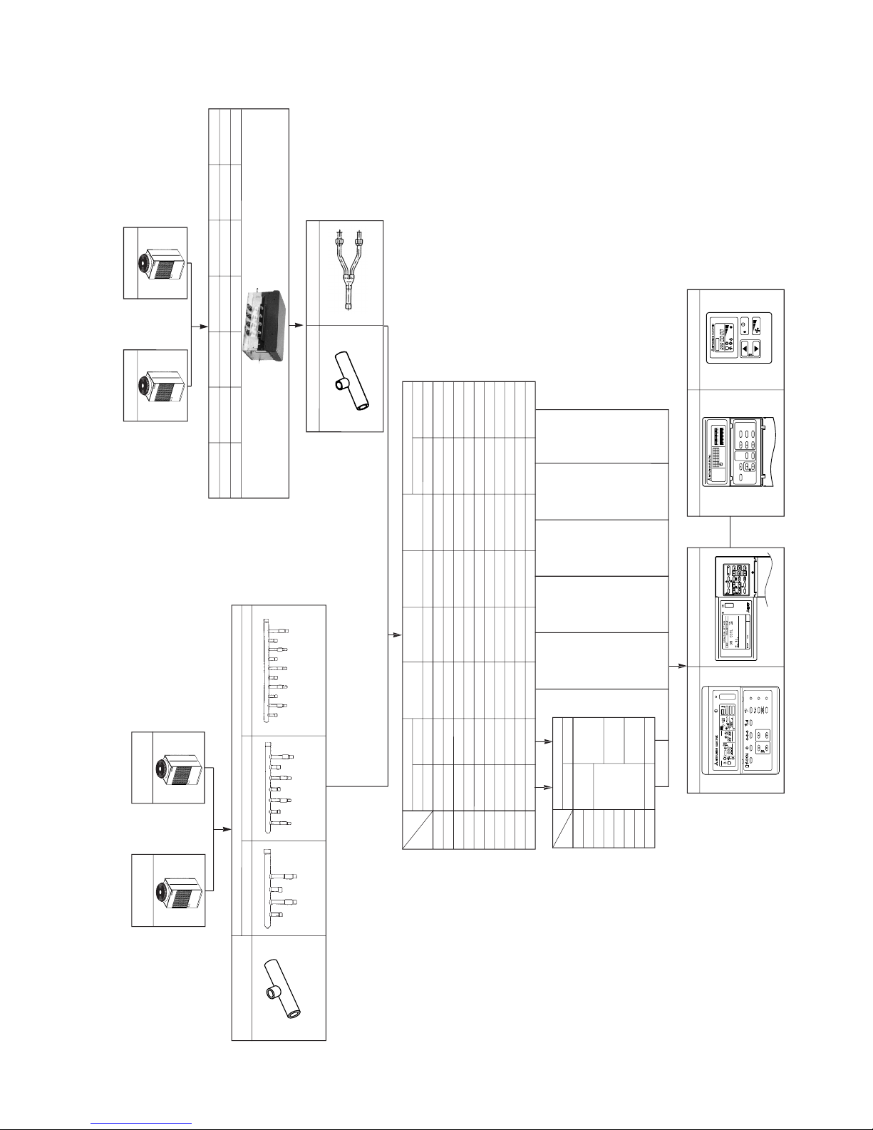
[3] Equipment Composition
40LW-F
A. Outdoor Unit
PURY-200YMF-B
PURY-P200YMF-B
PURY-250YMF-B
PURY-P250YMF-B
B. BC controller
Branch pipe kit
CMY-Y102S-F CMY-Y102L-F
D. Indoor Unit
Cassette ceiling
Ceiling concealed Wall mounted Ceiling suspended
Floor standing
Exposed Concealed
PLFY-P PLFY-P PEFY-P PKFY-P PCFY-P PFFY-P PFFY-P
4-way flow 2-way flow
20 - 20VLMD 20VM 20VAM - 20VLEM 20VLRM
25 - 25VLMD 25VM 25VAM - 25VLEM 25VLRM
32 32VKM 32VLMD 32VM 32VGM - 32VLEM 32VLRM
40 40VKM 40VLMD 40VM 40VGM 40VGM 40VLEM 40VLRM
50 50VKM 50VLMD 50VM 50VGM - 50VLEM 50VLRM
63 63VKM 63VLMD 63VM - 63VGM 63VLEM 63VLRM
80 80VKM 80VLMD 80VM - - - -
100 100VKM 100VLMD 100VM - 100VGM - -
125 125VKM 125VLMD 125VM -
125VGM
--
E. Option (Panel)
Decoration panel
PLP- CMP-
20
25
32
40
50
63
80
100, 125
3GB
6GB
32LW-F
63LW-F
125LW-F
Model
Capacity
Model
Capacity
PAR-F25MA
F. Remote Controller
C. Branch pipe kit/joint pipe kit
4-branch type
CMB-P104V-D
5-branch type
CMB-P105V-D
6-branch type
CMB-P106V-D
8-branch type
CMB-P108V-D
10-branch type
CMB-P1010V-D
13-branch type
––
16-branch type
CMB-P104V-E CMB-P105V-E CMB-P106V-E CMB-P108V-E CMB-P1010V-E CMB-P1013V-ECMB-P1016V-E
Joint pipe kit
CMY-R160-F: for V-D type
CMY-R160-G: for V-E type
Ceiling mounted
built-in
71
-
-
-
PDFY-P
20VM
25VM
32VM
40VM
50VM
63VM
80VM
100VM
125VM
71VM
-
-
--
MJ-103MTRA
PAC-SC32PTA
PAC-SE51CRA
A. Outdoor Unit
PUHY-200YMF-B
PUY-200YMF-B
PUHY-P200YMF-B
PUHY-250YMF-B
PUY-250YMF-B
PUHY-P250YMF-B
B. Branch pipe kit
Branch joint
Branch header
4-connection 7-connection 10-connection
CMY-Y107-ECMY-Y104-E CMY-Y1010-ECMY-Y102S-F CMY-Y102L-F
12
6
3
GROUP
SELECT
MODE
TEST RUN
AIR
DIRECTION
FAN SPEED
ON/OFF
0
87
54
CLOCK/
PATTERN
PROHIBITION
TIMER
MODE
TEMP.
REMOTE
MJ-103MTRA
CENTRAL CONTROLLER
9
INS.
DEL.
SCREEN
BACK
ENTER
VENTILATION
RESET
ON/OFF
SMTWTFS
SET
SET BACK
036912
12 15 18 21 24
SET/MONITOR TODAY
WEEKLY
SETTING
PROGRAM TIMER
PAC-SC32PTA
DAILY
SETTING
ON
SET BACK ON
CLOCK
OFF
DAILY TIMER
OFF
SET BACK
CENTRAL
TEMP.CHECK
˚C
TEMP.
ON/OFF
PAC-SE51CRA
Page 26
–24–
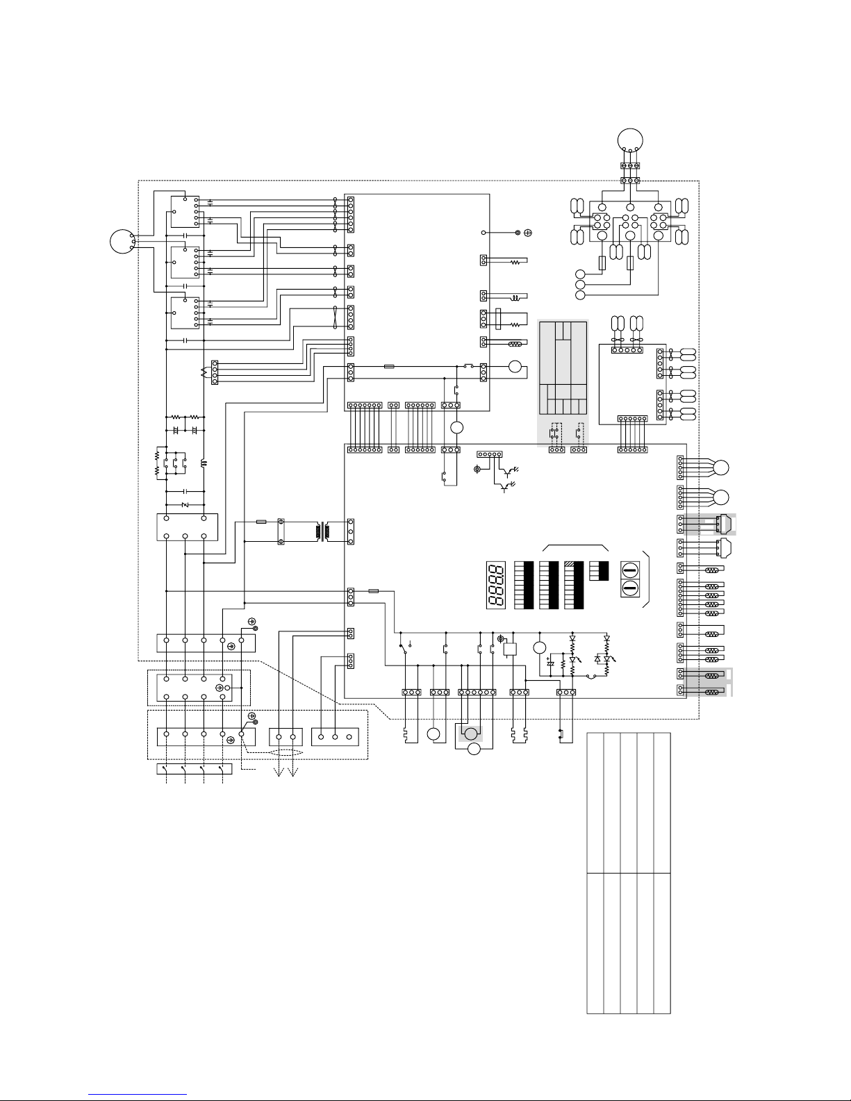
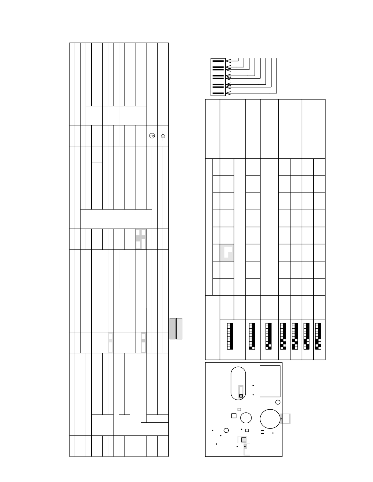
[4] Electrical Wiring Diagram
1 PU(H)Y-(P)200·250YMF-B
kQ
r
lQ
lP
kP
P
m
kR
od
@@
ioQ
qU
kdc@
|
T
Q
f
j
f
j
f
j
f
j
f
j
f
j
bmle
vfQ
tjP
tfQ
rbql
tfP
t
tjQ
vjP
vjQ
v
vfP
ujP
ufP
ujQ
ufQ
u
t
kP
q
kQ
eQ
kP
v
kR
v
kQ
eP
UOOu‘b
W‘@e
kR
le
S
P
Q
R
UOOu‘b
W‘@e
a
bmOS
u
q
tfQ
S
v
a
T
tfP
tjP
tjQ
T
U
TSRQPPQRST
R
Q
P
vfQ
e@
@
@ie@j
vjQ
vfP
vjP
ufQ
ujQ
ufP
ujP
@ @nm@ @l @QTOD
@rvR|PO@ @nee@ @l @QOOD
PQ P SQ
R
PRQ
P
RQS
S
PPQR UV
P
W
R
P
Q
QP
P
Q
P
R
V
PQ
U
R
Q
P
T
QR
S
S
R
T
R
P
Q
Q
P
RS
P
T
T
Q
U
R
P
S
Q
Q
R
T
P
Q
R
S
T
U
eOP
QTOu‘b
Q‘@e
bmOX
iQoj
R
bmOU
iQoj
bmRR
iRoj
P
P
bmRc
iRoj
bmRT
iRoj
bmRr
iRoj
R
bmQO
iRoj
Q
bmebP
iUoj
Q
bmRS
iUoj
R
Q
Q
P
bmQ|R
iQoj
U
P
T
bmubbS
iQoj
S
R
R
Q
P
P
R
bmrP
iQoj
Q
bmTP
iToj
P
bm‘bQ
iRoj
P
Q
Q
bmrQ
iRoj
R
P
bmwPO
iRoj
bmq
iRoj
Q
bmTQb
iRoj
R
bmucb
iSoj
bmRW
iRoj
bmsg
iQoj
wOQ
wOP
PPO
e
@
PO
t@
@
@
nmFP
PPO
rvP
rvtQ rvtP
neeFO
nmFP
rvQ
neeFO
rvR
POP
neeFO
nmFP
kcP
P
r|
@
ie @rvPFP‘PO
@
@@
@j
PQu
me@a
m
TFs
SFb
@nm^nee
bOSV
m
wPO
kR
o@
Rm‘
RWO^SOO^SPTu
TOg
qORX
cQS
qORV
obOP
qORW
obOV
cQT
qPTW
qPTV
c‘OSO
anw@ancx
b
@
@
il‘hm@ j
f^
x
a
SR
QP
a
q
v
rrq
wOS
wOT
me
ruP
kduP
bgP
QPrS
saP‘
ruQ
kP
bgQ
kQ
bgR
kQ
eP
QTOu‘b
Q‘@e
URg
kR
m
kP
kQ
kR
m
PQR
sgP
sgQ
sgVsgWsgT
sgU
sgRsgS
a
v
q
URgr
kP
rkdu
kR
kQ
od
s
@@@@@a
kP
od
saP
v
q
a
a
f/
x
b
@
h
@
t@
saR
lP
lQ
saV
‘
cr
bP
‘|
‘
{
ymqS
bP
qT
qP
TQb
{
sqlP
{
cbk
bQ
bR
qQ
qR
sOP
eR
QTOu‘b
P‘@e
bmsqP
sqlQ
bP
bQdP
aQ
dQ
dQ
dP
aP
aP
dP
dQ
dQ
aQ
bQdP
bP
sqlR
bQdP
aQ
dQ
dQ
dP
aP
bPS
bPT
bPU
SR
cbbs
QP
v
bQT
t
bQQbQP
bQSbQR
bQO
v
lb
u
lib
j
qa
RQ P
ef
PQ
Q
RS
P
PQ
Q
RS Q
PR
PQ
Q
PQ
P
PP
Q
QR
P
ST
R
U
Q
Q
R
S
P
Q
P
V
U
T
S
R
Q
P
T
U
P
Q
R
TQb
wOQ
wOP
wPO
bmqrQ
iVoj
bmubbQ
iQoj
bmubbR
iUoj
bmbs
iSoj
bmubbP
iUoj
bmqrR
iVoj
bmOT
iSoj
bme‘m
iRoj
bmOR
iRoj
bmQ|Q
iQoj
bmOQ
iWoj
sggr
bmOP
iQoj
bmg
iRoj
bmQ|P
iQoj
bmk
iRoj
bmRQ
iRoj
bmkuP
iToj
bmsq
iRoj
bmkuQ
iToj
bmR
iUoj
bmkQ
iQoj
bmROu
iQoj
leP
o
qV
eaU
a
x
n
kQ
o@
@
ihmu@
j
anw@ancx
h
b
@a
q
a
a
o
a
x
v
q
a
n
q
a
bmv
iToj
bmu
iToj
bmebQ
iUoj
bmt
iToj
vhqhmf@ch‘fq‘l
P|Q
nm
nee
nm
nee
P|R
nm
nee
bmRc
l
‘
m
gd‘s
bnnk
nmFP
neeFO
rvS
PS
Appliance
PUHY-P200/250YMF-B
PUY-P200/250YMF-B
PUHY-200/250YMF-B
PUY-200/250YMF-B
Difference
All exists
” 1” are not existed
” 2” are not existed
” 1” and ” 2” are not existed
1
2
2
1
<Difference of appliance>
URkr
PQR
a
v
q
sgPO sgX
Page 27
–25–
sgT
f
kduP
sgQ
q
sgW
f
sgV
v
W
Q
P
neeFO
nmFP
P
mDQ
mDPTmDPSmDPQmDPO
mDWmDUmDS
mDPU
mDP
mDPRm DPPmDX
mDVmDTmDR
mDQ mDT
mDX mDPR m DPU
mDU
mDPO m DPS
mDV
mDPP
mDP mDS mDW
mDPQ m DPT
TSRQPW
nmFP
neeFO
c
|
@
i@ @ j
ek‘ fVek‘ fP
QPrS
b
b@
Q
ruP
ek‘ fU
c
‘
n
@@ |
@
irvPj @kdc@
WPQRSTUV
Q
W
nmFP
neeFO
VU
UV
neeFO
nmFP
R
nmFP
WPQRST
neeFO
S
TSRQPW
nmFP
neeFO
VU
VU
UV
neeFO
nmFP
W
R
T
PQRST
VU
ST
c
@ @kdc@
i
jq
@rvP@
ek‘ fRek‘ fSek‘ fQ
ruQ
ek‘ fT
OOOO‘ XXXX
c
@@
@@ @
@@
rrq
OOOO‘ XXXX
c
@@
@@
@
@@
mDR
kdc@
h
@
··
PUHY-P
·
YMF-B
ek‘ f
ek‘ f
ek‘ f
ek‘ f
ek‘ f
ek‘ f
ek‘ f
ek‘ f
kcP
q@
ik
j
b@
P
ia
j
q@
@Q
h@
h@
h@
h@
ek‘ fW
sgU
lb
rkdu
sgP
URgr
URg
n
ruQ
ruP
‘ bbtltk
‘ snq
sgR
a
sgS
x
h
b
a
ie j
ek‘ fW@
@
@
@
nm
k
@@
@@ @ C
s@@@
k
@@
a@@
s@@@^
k
@@
@
s@@@
X
X
X
X
X
X
XPO
PO
PO
PO
PO
PO
PO
sgR
sgT
sgS
sgQ
q@
@
qQCqR
u
b
bQCbR
m@@@r
o@
g@
i@
@
j
i
@QSOu@
@ODPP‘ j
leP
cbk
eP‘ R
saPi‘ j
saV
r
le
q
@
e
r
r@
io @
@
j
q
c
rxlank@dwok
‘ m ‘ shnm
b@is
j
ruPCruQ
kQ
cb@
i ‘
@
@
@
j
cbbs
o@
saR
TQb
sgP
b
@r
qU
qV
ih
@@
j
sggr
qPCqT
q@
@
bPCPSCPTCPU
ymqS
lblb
@@@@@@@@@ir | @ @
j
d
@
@
in @
j
URgr
URg g @
@
b@
bgQCbgR
r
@
@
ic
|
@
j
kduP
S| @QPrS
1
rkdu
g@
@
k@
@
URkr
m@@@r
rvQCRCS
r@
rvtP‘ Q
b
@@D
q
@
@D@
k
r
e
@
‘ D@
k
@
t
‘
@
@
@@ D@
g@
@
@D
n ‘ @D@
o@ D@
@
@D@
@@@ @r | @
@
@D@
@@@ @r | @
m@ @ @
eaU
e
l
@
m@@@
rrq r @
@
s
sP
ib
@
@
@
j
bgP b
@
ib
j
d
@
@
cr c @
sqlP‘ Ro @
@
me m @e
sgPO
sgX
sgW
sgV
sgU
wPCQCSCTCPO
kcP
bQO‘ QT
e
@
t@
@
c
@
@|
r
s
rvPr
@D
@D@
c
@@D@
s
s
s
i
b
@
bmbs
bmqrQCR
b
bmubbPCR
bmebPCQ
bmubbQCS
b
l|h@s
u
u
o@
@
d@
q@
PUHY-P
·
YMF-B only
H/P unit (PUHY) only
1
2
2
2
2
1
2
2
sgPO
a
URkr
sgX
o
QPrS
1 PU(H)Y-(P)200·250YMF-B
Page 28
–26–
CNTR
(3P)
CN3
(6P)
CNL2
(2P)
CN30V
(2P)
MF1
Purple
R7
FB6
Black
Yellow
Orange
L2
Power circuit board
(INV board)
BOX BODY
Inverter
Controller Box
Red
Brown
Black
Purple
Black
Yellow
White
Red
Brown
Orange
Red
Blue
CNW
(5P)
CNV
(5P)
CNFC2
(6P)
CNU
(5P)
SW4
41
OFF:0
ON:1
SV4
X07
X06
12345
6
(6P)
CN36
SV6
X09
X08
12345
6
(6P)
CN37
SV3
SV5
22
(5P)
CNLV1
(3P)
CN32
(3P)
CNL
(2P)
CN2-1
(3P)
CNH
(2P)
CN01
THHS
(8P)
CN02
(2P)
CN2-2
(3P)
CN03
(3P)
CNFAN
(4P)
CN05
(7P)
CNRS3
(6P)
CNVCC1
(4P)
CNCT
(6P)
CNVCC3
(2P)
CNVCC2
(7P)
CNRS2
X10
X01
X02
52C
32165
1234567121432
2
6
3
54
1
32
2
11
1
21
2
21
31
243
2
21
1
43
2
21
FG
123
BlackRed
Motor (Compressor)
V
MC
W
C20
C23 C24
C21 C22
U
C25
White
12
DCCT
34
C16
C15
C14
B1
E1
E2
E2
B2
C2E1
TRM3
C1
C2E1
B2
E2
E2
E1
B1
B1
E1
E2
E2
B2
C2E1
C1
TRM2
CNTR1
1A F
250VAC
F3
T01
R3
R2
C3
C2
DCL
+
TRM1
+
52C
R1
R5
C1
ZNR4
+
~
-~
C1
DS
~
TB7
M2
M1
TB3
Unit body
controller
remote
Indoor and
Connect to
Yellow
Green/
Blue
Black
Red
White
TB1
PE
L1
Terminal Box
PE
L2
L3
SLEV
L1
63LS
Red
White
Black
321
63HS
Red
White
Black
TH4 TH3
TH6
TH5
TH7
TH2
TH1
321
N
L3
L2
L1
N
L3
63H
2A F
250VAC
F1
L2
CH3
L2
CH2
L1
SV2
TB1A
21S4
CH1
SV1
NF
X05
X04
SSR
White
Red
Black
12
34
Blue
Yellow
Green/
(MAIN board)
Control circuit board
BOX BODY
DA040
R157
R158
D25
PC07
R038
PC01
R037
D24
R039
50Hz
380/400/415V
3N~
Power source
L3
X10
N
C047
4:Compressor ON/OFF
5:Trouble
N
NF Box
12V
switch
the following table)
(For SW1:1~10display see
Self-diagnosis selector
1
LD1
ON:1
OFF:0
110
*1
SW3
OFF:0
SW2
ON:1
OFF:0
SWU1SWU2
SW1
101
ON:1
*1
Unit address setting switch
10
switch
Function selector
101
X01
X02
(2P)
CNTH
(3P)
CN38
(4P)
CNVDC
3
(3P)
CN52C
2
(3P)
CNR
(3P)
CNX10
1
3
(3P)
CNS2
221
(3P)
CNAC2
1
(5P)
CN51
2
(2P)
CNS1
3112334
(2P)
CNVCC4
516
(2P)
CN2-3
122
3
(6P)
CN34
2
(6P)
CNFC1
2
(3P)
CN20
3
(3P)
CN3S
(3P)
CN35
(3P)
CN3D
1
1
(3P)
CN33
(2P)
CN06
3
(2P)
CN09
2A F
250VAC
F01
65432
1
5322413
625
112
3
5
3
4
4325
1
2
3
6217
3
1
2
1122
1
3
8
1
763211
4
423
1
231
3
24121
SW3-10 are OFF for Model 200.
and ON for Model 250.
VK1
VG1
VK2
VG2
WK1
WG1
WK2
(Fancon board)
Fan control board
WG2
123
54321 12345
6
5
UK2
UK1
UG1
5
Black
White
4
UG2
Red
V
CN04
Black
8A F
600VAC
321
4
MF
L3
8A F
600VAC
F1
L2
W
L3
White
L1
F2
L2
Red
L1
U
V
VG2
VK2
VG1
VK1
WG1
W
WK2
WK1
UK2
U
UG1
SCRM
UG2
UK1
WG2
CNMF
K
G
K
G
K
G
K
G
K
G
K
G
2
5
display
self-diagnosis
LED for
R6
5
TH10
PE
L3
N
1
L1
M1
M2
S
L2
4
3
CNRT1
(5P)
1
2
Terminal
Block
Noise
Filter
Crank case heater
(Compressor)
Cord heater
(Accumulator liquid
level detect)
switch
High Pressure
Fan motor
(Heat exchanger)
Fuse
Fuse
Fuse
Terminal Block
Diode stack
to TB1A
TH9
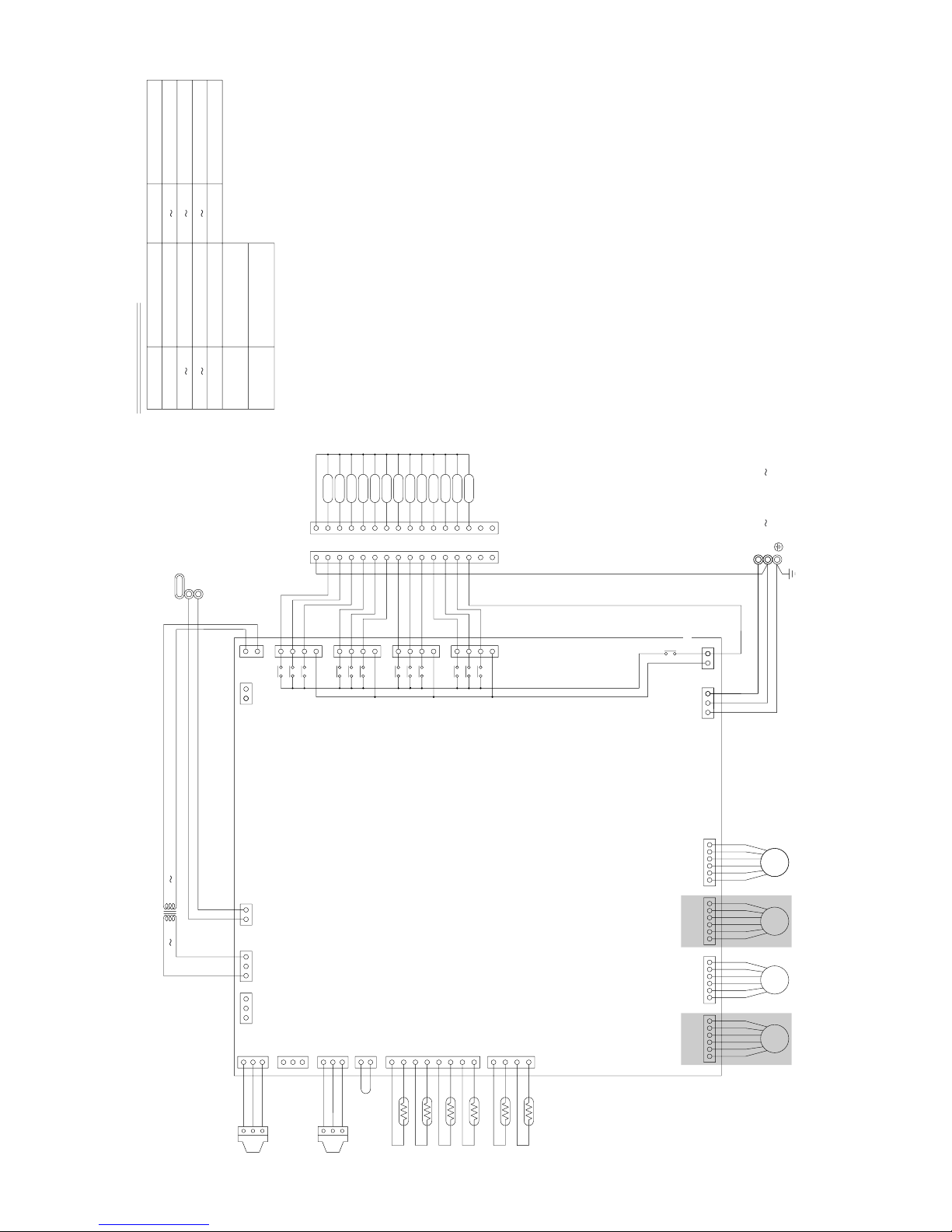
Appliance
PURY-P200/250YMF-B
PURY-200/250YMF-B
Difference
All exists
” 2” are not existed
<Difference of appliance>
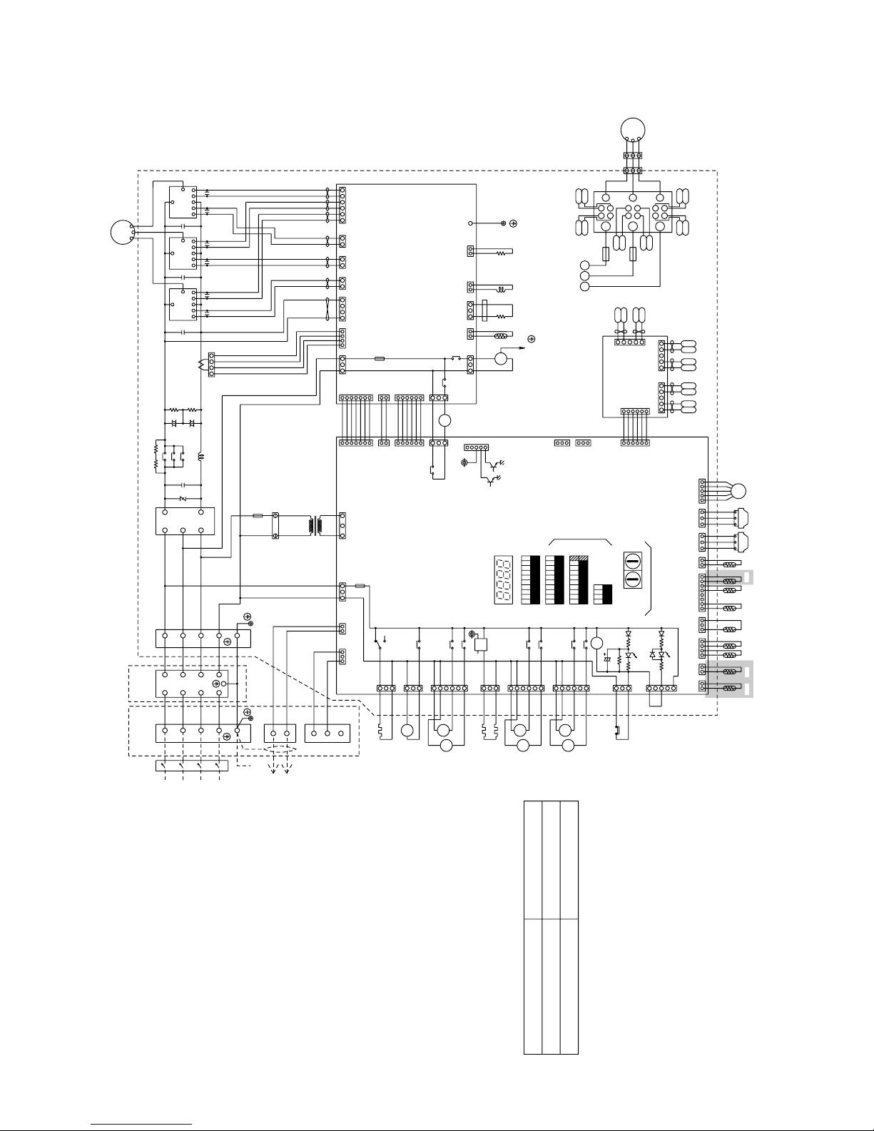
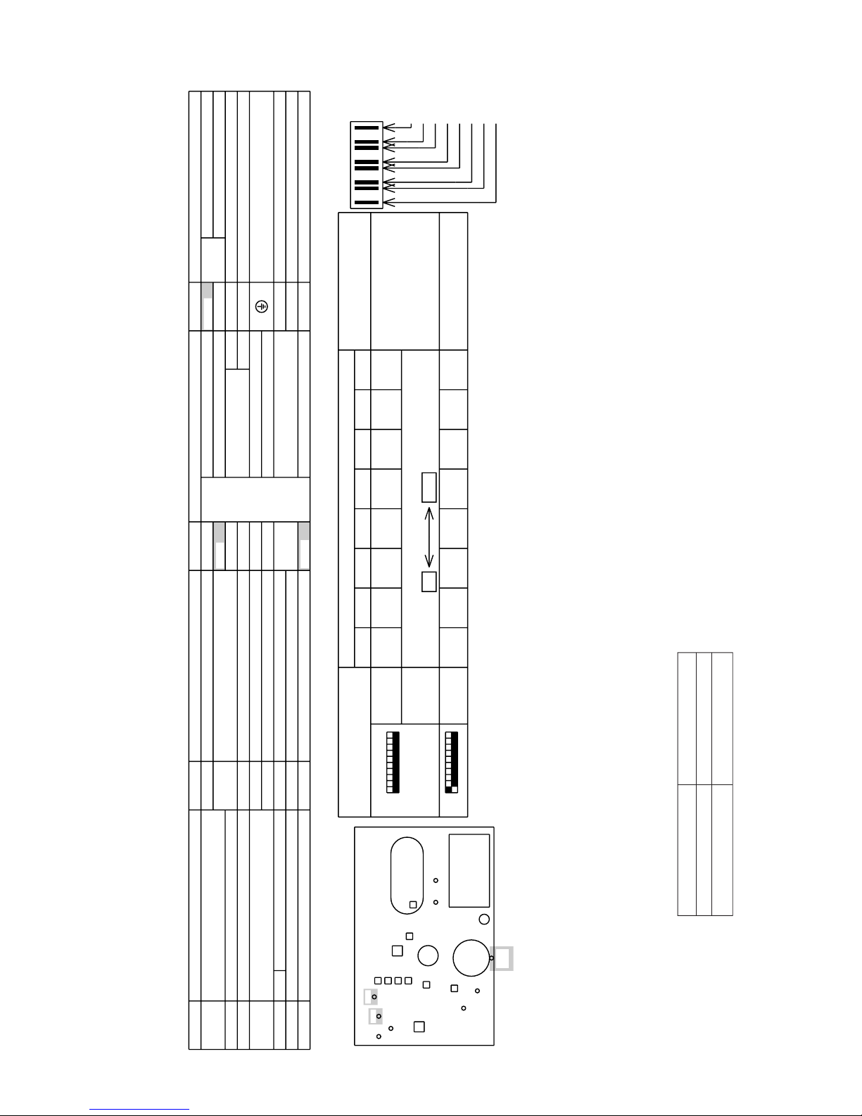
2 PURY-(P)200·250YMF-B
Page 29
–27–
FLAG8 always lights at
microcomputer power
ON
(Front)
Inverter
Controller
Box
TH4TH3
ACCUMULATOR
63LS
SV1
SV2
TH10
Blown
Oil
separator
21S4
63H
63HS
TH1
SLEV
MC
FLAG8
Check display1
(Blinking)
Relay output
display
(Lighting)
LD1
FLAG8
FLAG1
FLAG2
FLAG3
FLAG4
FLAG5
FLAG6
FLAG7
<Internal layout>
<LED display>
FLAG5
SV2
FLAG2 FLAG4FLAG3
Display at LED lighting(blinking)Remarks SW1 operation
76543218
<Operation of self-diagnosis switch(SW1)and LED display>
Always
lighting
Display
FLAG6
SV1
Crankcase
heater
21S4
FLAG1 FLAG7
(at factory shipment)
During
compres-
sor run
ON:1
OFF:0
<SYMBOL EXPLANATION>
109
For PURY-(P)200/250YMF-B
*2
*2
51 1102
*please refer to the service handbook about other switch settings of LED display.
SV6
SV5
SV4
SV3
TH2
TH9
TH7
TH6
*2
TH5
Display the address and error code by turns
76543218
ON:1
OFF:0
109
SV3 SV4
SV5 SV6 SSR
NameSymbol
MF1
DCL
Symbol
Radiator panelFan
(Power factor improvement)
Choke coil(Transmission)L2
SV1,SV2
DC reactor
DCCT
52C
TH1
Current Sensor
(Inverter main circuit)
THHS
ZNR4 Electronic expansion valve(Oil return)
63HS
Solenoid valve (Discharge-suction bypass)
4-way valve21S4
SLEV
High pressure sensor
Low pressure sensor63LS
NameSymbol
Compressor shell temp.
Radiator panel temp. detect
Lower
Symbol
Aux. relay
Upper
Accumurator liquid
High pressure liquid temp.
temp. detect
OA temp. detect
Iiquid outlet temp.detect
Pipe temp. detect
at Sub-cool coil
Name
Magnetic contactor
Name
SSR Solid state relay TRM1~3 Power transistor module
TH10 *2
TH9 *2
TH7
TH6
X1,2,4~10
Saturation evapo. temp. detect
Discharge pipe temp. detectThermistor
Earth terminal
(Heat exchanger capacity control)
SV3~SV6
FB6 Ferrite core
Solenoid valve
Varistor
TH2 *2
TH4
TH5
TH3
Thermistor
<Difference of appliance>
Appliance Difference
PURY-P200/250YMF-B All exists
PURY-200/250YMF-B ”*2” are not existed
2 PURY-(P)200·250YMF-B
Page 30
–28–
Symbol explanation
PE
3
2
1
3
2
1
EARTH
Terminal block
(for Transmission)
TB02
Terminal block
(for power source)
TB01
Note:TB02 is terminal block for transmission.
Never connect power line to it.
NameSymbol
Solenoid valve
Solenoid valve
Solenoid valve
Solenoid valve
Expansion valve
Thermister sensor
Transformer
NameSymbol
SV1 4A
SV1 4B
SV1 4C
SVM
TR
TH11 16
LEV1 4
PS1,3 Pressure sensor
Transmission line
Shield wire
* Only for CMB-P-V-D
/N 220V 240V 50Hz
Power source
BC Board
31
LEV1
TB01
16
15
14
13
12
11
10
9
8
7
6
5
4
3
2
1
16
15
14
13
12
11
10
9
8
7
6
5
4
3
2
1
SVM
SV4B
SV4A
SV4C
SV3B
SV3A
SV3C
SV2B
SV2A
SV2C
SV1C
SV1A
SV1B
}
CN38
3
1
CNTR
CN02
CN12
153
31
7
5
3
1
7
5
3
1
7
5
3
1
7
5
3
1
TR
3
CNVCC1
12
X2
X1
X30
X4
X3
X31
X6
X5
X32
X8
X7
X33
X21
}
DC 30V
123456 654321654321654321
LEV4 LEV3 LEV2
1
2
3
CNP1
1
2
3
CNP2
1
2
3
CNP3
2
1
1
2
3
4
5
6
7
8
4
3
2
1
12321
CN03
CN13
CN10
CN11
CN08 CN07 CN06 CN05
L
N
TH11
TH12
TH13
TH14
TH15
TH16
PS1
PS3
20 22V
TB02
M2
M1
CN26
CN27
CN28
CN29
TB01
220 240V
CN36
3 CMB-P104V-D
CMB-P104V-E
Page 31

–29–
4 CMB-P105V-D
CMB-P105V-E
Symbol explanation
PE
3
2
1
3
2
1
EARTH
Terminal block
(for Transmission)
TB02
Terminal block
(for power source)
TB01
Note:TB02 is terminal block for transmission.
Never connect power line to it.
NameSymbol
Solenoid valve
Solenoid valve
Solenoid valve
Solenoid valve
Expansion valve
Thermister sensor
Transformer
NameSymbol
SV1 5A
SV1 5B
SV1 5C
SVM
TR
TH11 16
LEV1 4
PS1,3 Pressure sensor
Transmission line
Shield wire
* Only for CMB-P-V-D
/N 220V 240V 50Hz
Power source
BC Board
31
LEV1
TB01
16
15
2
1
2
1
14
13
12
11
10
9
8
7
6
5
4
3
2
1
16
15
14
13
12
11
10
9
8
7
6
5
4
3
2
1
SV4B
SV4A
SV4C
SV3B
SV3A
SV3C
SV2B
SV2A
SV2C
SV1C
SV1A
SV1B
}
CN38
3
1
CNTR
CN02
CN12
153
31
7
5
3
1
7
5
3
1
7
5
3
1
7
5
3
1
TR
3
CNVCC1
12
X2
X1
X30
X4
X3
X31
X6
X5
X32
X8
X7
X33
X21
}
DC 30V
123456 654321654321654321
LEV4 LEV3 LEV2
1
2
3
CNP1
1
2
3
CNP2
1
2
3
CNP3
2
1
1
2
3
4
5
6
7
8
4
3
2
1
12321
CN03
CN13
CN10
CN11
CN08 CN07 CN06 CN05
L
N
TH11
TH12
TH13
TH14
TH15
TH16
PS1
PS3
20 22V
TB02
M2
M1
CN26
CN27
CN28
CN29
TB01
220 240V
SV5C
SV5A
SV5B
7
5
3
1
X10
X9
X34
CN30
SVM
CN36
Page 32

–30–
5 CMB-P106V-D
CMB-P106V-E
PE
3
2
1
3
2
1
EARTH
Note:TB02 is terminal block for transmission.
Never connect power line to it.
Transmission line
Shield wire
* Only for CMB-P-V-D
/N 220V 240V 50Hz
Power source
BC Board
31
LEV1
TB01
SV6B
SV6A
SV6C
16
15
14
13
12
11
10
9
8
7
6
5
4
3
2
1
16
15
14
13
12
11
10
9
8
7
6
5
4
3
2
1
SV5C
SV5A
SV5B
SV4B
SV4A
SV4C
SV3B
SV3A
SV3C
SV2B
SV2A
SV2C
SVM
SV1C
SV1A
SV1B
}
4321
1234
CN38
3
1
CNTR
CN02
CN12
153
31
7
5
3
1
7
5
3
1
7
5
3
1
7
5
3
1
7
5
3
1
7
5
3
1
TR
3
CNVCC1
12
X2
X1
X30
X4
X3
X31
X6
X5
X32
X8
X7
X33
X10
X9
X34
X12
X11
X35
X21
}
DC 30V
123456 654321654321654321
LEV4 LEV3 LEV2
1
2
3
CNP1
1
2
3
CNP2
1
2
3
CNP3
2
1
1
2
3
4
5
6
7
8
4
3
2
1
12321
CN03
CN13
CN10
CN11
CN08 CN07 CN06 CN05
L
N
TH11
TH12
TH13
TH14
TH15
TH16
PS1
PS3
20 22V
TB02
M2
M1
CN26
CN27
CN28
CN29
CN30
CN31
TB01
220 240V
CN36
Symbol explanation
Terminal block
(for Transmission)
TB02
Terminal block
(for power source)
TB01
NameSymbol
Solenoid valve
Solenoid valve
Solenoid valve
Solenoid valve
Expansion valve
Thermister sensor
Transformer
NameSymbol
SV1 6A
SV1 6B
SV1 6C
SVM
TR
TH11 16
LEV1 4
PS1,3 Pressure sensor
Page 33

–31–
6 CMB-P108V-D
CMB-P108V-E
* Only for CMB-P-V-E
PE
3
2
1
3
2
1
EARTH
}
Power source
}}
L
N
Power source
/N 220V 240V 50Hz
Note:TB02 is terminal block for transmission.
Never connect power line to it.
Transmission line
Shield wire
SV10B
SV10A
SV10C
SV9B
SV9A
SV9C
BC Board
CN38
1
3
1
CNTR
CN50
CN51
7654321123456
CN02
CN12
153
31
7
5
3
1
7
5
3
1
7
5
3
1
7
5
3
1
7
5
3
1
7
5
3
1
3
TR
3
CNVCC1
12
X2
X1
X30
X4
X3
X31
X6
X5
X32
X8
X7
X33
X10
X9
X34
X12
X11
X35
X21
}
DC 30V
12345 6 654321654321654321
LEV4 LEV3 LEV2 LEV1
1
2
3
CNP1
1
2
3
CNP2
1
2
3
CNP3
2
1
1
2
3
4
5
6
7
8
4
3
2
1
123
21
CN03
CN13
CN10
CN11
CN08 CN07 CN06 CN05
CN36
TH11
TH12
TH13
TH14
TH15
TH16
PS1
PS3
20 22V
TB02
M2
M1
CN26
CN27
CN28
CN29
CN30
CN31
TB01
220 240V
LEV1
7654321
CN35
TB01
SV6B
SV6A
SV6C
SVM
16
15
14
13
12
11
10
9
8
7
6
5
4
3
2
1
16
15
14
13
12
11
10
9
8
7
6
5
4
3
2
1
RELAY4 Board
SV5C
SV5A
SV5B
SV4B
SV4A
SV4C
SV3B
SV3A
SV3C
SV2B
SV2A
SV2C
CN32
CN33
CN34
CN39
3
1
SV7C
SV7A
SV7B
SV8C
SV8A
SV8B
SV1C
SV1A
SV1B
X14
X13
X36
X37
X15
X16
98765432116 15 1011121314
12345678910111213141516
X18
X17
X38
X39
X19
X20
CN52
5731753175317533 31
Symbol explanation
Terminal block
(for Transmission)
TB02
Terminal block
(for power source)
TB01
NameSymbol
Solenoid valve
Solenoid valve
Solenoid valve
Solenoid valve
Expansion valve
Thermister sensor
Transformer
NameSymbol
SV1 8A
SV1 8B
SV1 8C
SVM
TR
TH11 16
LEV1 4
PS1,3 Pressure sensor
Page 34

–32–
7 CMB-P1010V-D
CMB-P1010V-E
* Only for CMB-P-V-E
PE
3
2
1
3
2
1
EARTH
}
Power source
}}
L
N
Power source
/N 220V 240V 50Hz
Note:TB02 is terminal block for transmission.
Never connect power line to it.
Transmission line
Shield wire
SV10B
SV10A
SV10C
SV9B
SV9A
SV9C
BC Board
CN38
1
3
1
CNTR
CN50
CN51
7654321123456
CN02
CN12
153
31
7
5
3
1
7
5
3
1
7
5
3
1
7
5
3
1
7
5
3
1
7
5
3
1
3
TR
3
CNVCC1
12
X2
X1
X30
X4
X3
X31
X6
X5
X32
X8
X7
X33
X10
X9
X34
X12
X11
X35
X21
}
DC 30V
12345 6 654321654321654321
LEV4 LEV3 LEV2 LEV1
1
2
3
CNP1
1
2
3
CNP2
1
2
3
CNP3
2
1
1
2
3
4
5
6
7
8
4
3
2
1
123
21
CN03
CN13
CN10
CN11
CN08 CN07 CN06 CN05
CN36
TH11
TH12
TH13
TH14
TH15
TH16
PS1
PS3
20 22V
TB02
M2
M1
CN26
CN27
CN28
CN29
CN30
CN31
TB01
220 240V
LEV1
7654321123456
CN35
TB01
SV6B
SV6A
SV6C
SVM
16
15
14
13
12
11
10
9
8
7
6
5
4
3
2
1
16
15
14
13
12
11
10
9
8
7
6
5
4
3
2
1
RELAY4 Board
SV5C
SV5A
SV5B
SV4B
SV4A
SV4C
SV3B
SV3A
SV3C
SV2B
SV2A
SV2C
CN32
CN33
CN34
CN39
3
1
SV7C
SV7A
SV7B
SV8C
SV8A
SV8B
SV1C
SV1A
SV1B
X14
X13
X36
X37
X15
X16
98765432116 15 1011121314
12345678910111213141516
X18
X17
X38
X39
X19
X20
CN52CN53
5731753175317533 31
Symbol explanation
Terminal block
(for Transmission)
TB02
Terminal block
(for power source)
TB01
NameSymbol
Solenoid valve
Solenoid valve
Solenoid valve
Solenoid valve
Expansion valve
Thermister sensor
Transformer
NameSymbol
SV1 10A
SV1 10B
SV1 10C
SVM
TR
TH11 16
LEV1 4
PS1,3 Pressure sensor
Page 35

–33–
8 CMB-P1013V-E
PE
EARTH
1
2
3
1
2
3
TB02
TB01
Name
Symbol
Terminal block
(for Transmission)
Solenoid valve
Solenoid valve
Solenoid valve
Solenoid valve
Terminal block
(for power source)
Pressure sensor
Expansion valve
Thermister sensor
Transformer
Name
SV1~13A
SV1~13B
SV1~13C
SVM
Symbol
TR
TH11~16
LEV1,3
PS1,3
M1
M2
DC 30V
}
Shield wire
Transmission line
Power source
}
L
N
Power source
~/N 220V~240V 50Hz
RELAY10
Board
BC Board
CN39
13
654321 1234567
CN51
CN50
135
CN12
13
CNOUT3
CNOUT1
1
3
5
7
1
3
5
7
1
3
5
7
1
3
5
7
1
3
5
7
1
3
5
7
1
3
5
7
1
3
5
7
7
5
3
1
1571571357
13
21
CNVCC2
3
CN42
X46
X47
X48
1
2
3
8
7
6
5
4
3
2
1
4
CNOUT2
CNOUT4
CN41
CN40
X41
X44
X40
X43
X42
X45
X20
X18
X19
X17
X39
X38
3
CNVCC1
12
X16
X15
X37
X36
X13
X14
X2
X1
X30
X4
X3
X31
X6
X5
X32
X8
X7
X33
X10
X9
X34
X12
X11
X35
X21
6
5432
1
6
5432
1
LEV3 LEV1
1
2
3
CNP1
1
2
3
CNP3
2
1
1
2
3
4
5
6
7
8
4
3
2
1
12321
CN03
CN02
CN13
CN10
CN11
CN07 CN05
33
CN34
CN33
1357
CN32
TH11
TH12
TH13
TH14
TH15
TH16
TR
TB02
CN38
CN26
CN27
CN28
CN29
CN30
CN31
TB01
CN35
3
1
CNTR
4
1
2
3
4
5
6
7
8
3
2
1
SV1B
SV1A
SV1C
SV2C
SV2A
SV2B
SV3C
SV3A
SV3B
SV4C
SV4A
SV4B
SV5B
SV5A
SV5C
1
2
3
4
5
6
7
8
9
10
11
12
13
14
15
16
1
2
3
4
5
6
7
8
9
10
11
12
13
14
15
16
SV9C
SV9A
SV9B
SV10C
SV10A
SV10B
16 15 14 13 12 11 10 9 8 7 6 5 4 3 2 1
14 13 12 11 101516 123456789
SV8B
SV8A
SV8C
SV7B
SV7A
SV7C
SVM
SV6C
SV6A
SV6B
SV11C
SV11A
SV11B
16
15
14
13
12
11
10
9
8
7
6
5
4
3
2
1
9
8
7
6
5
4
3
2
1
16
15
14
13
12
11
10
SV12C
SV12A
SV12B
SV13C
SV13A
SV13B
PS1
PS3
Note : 1. TB02 is transmission terminal block.
Never connect power line to it.
2. The initial set values of switch on CONT.B are
as follows : SW1 : 0, SW2:0.
20 22V 220 240V
CN36
Page 36

–34–
9 CMB-P1016V-E
PE
EARTH
1
2
3
1
2
3
TB02
TB01
Name
Symbol
Terminal block
(for Transmission)
Solenoid valve
Solenoid valve
Solenoid valve
Solenoid valve
Terminal block
(for power source)
Pressure sensor
Expansion valve
Thermister sensor
Transformer
Name
SV1~16A
SV1~16B
SV1~16C
SVM
Symbol
TR
TH11~16
LEV1,3
PS1,3
M1
M2
DC 30V
}
Shield wire
Transmission line
Power source
}
L
N
Power source
~/N 220V~240V 50Hz
CN39
13
654321 1234567
CN51
CN50
135
CN12
13
CNOUT3
CNOUT1
1
3
5
7
1
3
5
7
1
3
5
7
1
3
5
7
1
3
5
7
1
3
5
7
1
3
5
7
1
3
5
7
7
5
3
1
1571571357
13
21
CNVCC2
3
CN42
X46
X47
X48
1
2
3
8
7
6
5
4
3
2
1
4
CNOUT2
CNOUT4
CN41
CN40
X41
X44
X40
X43
X42
X45
X20
X18
X19
X17
X39
X38
3
CNVCC1
12
X16
X15
X37
X36
X13
X14
X2
X1
X30
X4
X3
X31
X6
X5
X32
X8
X7
X33
X10
X9
X34
X12
X11
X35
X21
6
5432
1
6
5432
1
LEV3 LEV1
1
2
3
CNP1
1
2
3
CNP3
2
1
1
2
3
4
5
6
7
8
4
3
2
1
12321
CN03
CN02
CN13
CN10
CN11
CN07 CN05
33
CN34
CN33
1357
CN32
TH11
TH12
TH13
TH14
TH15
TH16
TR
TB02
CN38
CN26
CN27
CN28
CN29
CN30
CN31
TB01
CN35
3
1
CNTR
4
1
2
3
4
5
6
7
8
3
2
1
SV1B
SV1A
SV1C
SV2C
SV2A
SV2B
SV3C
SV3A
SV3B
SV4C
SV4A
SV4B
SV5B
SV5A
SV5C
1
2
3
4
5
6
7
8
9
10
11
12
13
14
15
16
1
2
3
4
5
6
7
8
9
10
11
12
13
14
15
16
SV9C
SV9A
SV9B
SV10C
SV10A
SV10B
16 15 14 13 12 11 10 9 8 7 6 5 4 3 2 1
14 13 12 11 101516 123456789
SV8B
SV8A
SV8C
SV7B
SV7A
SV7C
SVM
SV6C
SV6A
SV6B
SV11C
SV11A
SV11B
16
15
14
13
12
11
10
9
8
7
6
5
4
3
2
1
9
8
7
6
5
4
3
2
1
16
15
14
13
12
11
10
SV12C
SV12A
SV12B
SV13C
SV13A
SV13B
PS1
PS3
Note : 1. TB02 is transmission terminal block.
Never connect power line to it.
2. The initial set values of switch on CONT.B are
as follows : SW1 : 0, SW2:0.
1
2
2
1
1
3
5
7
1
3
5
7
1
3
5
7
X57
X53
X52
X56
X55
CN45
CN44
CN43
X50
SV14C
SV14A
SV14B
SV15A
SV15B
SV16C
SV16A
SV16B
SV15C
X54
X51
X49
RELAY10
Board
BC Board
20 22V 220 240V
CN36
Page 37

–35–
[5] Standard Operation Data
(1) Cooling operation
1 PU(H)Y-200·250YMF-B
Outdoor unit
Items
PUHY-200YMF-B
PUY-200YMF-B
PUHY-250YMF-B
PUY-250YMF-B
Indoor
Outdoor
Quantity
Quantity in operation
Model
Main pipe
Branch pipe
Total piping length
27.0/19.5 27.0/19.5
35.0/24.0 35.0/24.0
44
44
63 63 50 25 125 40 63 25
55
10 10 10 10 10 10 10 10
45 45
Hi Hi Hi Hi Hi Hi Hi Hi
12.2 13.8
440 440 380 280 430 350 440 280
80 85
111 111
22.0/4.80 20.3/4.7
(2.16/0.47) (1.99/0.46)
93 95
40 42
75
97
710
64
30 30
65
69 60
27 27
86
26 26
10 10
15.1 13.8 19.0 17.4
380 415 380 415
270/75 270/75 340/95 340/95
Indoor unit fan notch
Refrigerant volume
Total current
Volts/Frequency
Indoor unit
SC (LEV1)
Oil return (SLEV)
High pressure/Low pressure (after O/S)
(before MA)
Pressure
DB/WB
Set
–
m
–
kg
A
V
V/Hz
Pulse
kg/cm
2
G
(MPa)
˚C
Condition
Sectional temperature
Outdoor unit
LEV opening
Discharge (TH1)
Heat exchanger outlet (TH5)
Accumulator
Suction (Comp)
TH2
Liquid level
Shell bottom (Comp)
SCC outlet (TH7)
Bypass outlet (TH8)
LEV inlet
Heat exchanger outlet
Inlet
Outlet
Upper (TH4)
Lower (TH3)
Outdoor
unit
Indoor
unit
Ambient temp.
Indoor unit
Piping
Page 38

–36–
PUHY-P200·250YMF-B
Outdoor unit
Items
PUHY-P200YMF-B PUHY-P250YMF-B
Indoor
Outdoor
Quantity
Quantity in operation
Model
Main pipe
Branch pipe
Total piping length
27.0/19.5 27.0/19.5
35.0/24.0 35.0/24.0
44
44
63 63 50 25 125 40 63 25
55
10 10 10 10 10 10 10 10
45 45
Hi Hi Hi Hi Hi Hi Hi Hi
12.7 14.3
440 440 380 280 430 350 440 280
80 85
111 111
20.5/4.0 21.9/3.9
(2.01/0.39) (2.15/0.38)
96 96
40 42
77
10 10
12 15
–1 –1
11 11
34 34
19 19
80 85
27 27
86
26 26
10 10
0.23 0.23
15.9 14.5 19.9 18.2
380 415 380 415
270/75 270/75 340/95 340/95
Indoor unit fan notch
Refrigerant volume
Total current
Volts/Frequency
Indoor unit
SC (LEV1)
Oil return (SLEV)
High pressure/Low pressure (after O/S)
(before MA)
Pressure
DB/WB
Set
–
m
–
kg
A
V
V/Hz
Pulse
kg/cm
2
G
(MPa)
˚C
Condition
Sectional temperature
Outdoor unit
LEV opening
Inlet
Outlet
Upper (TH4)
Lower (TH3)
Outdoor
unit
Indoor
unit
αOC
Ambient temp.
Indoor unit
Piping
Discharge (TH1)
Heat exchanger outlet (TH5)
Accumulator
Suction (Comp)
CS circuit (TH2)
CS circuit (TH9)
Liquid level
Shell bottom (Comp)
SCC outlet (TH7)
Bypass outlet (TH8)
LEV inlet
Heat exchanger outlet
Page 39

–37–
380 415 380 415
270/75 270/75 340/95 340/95
15.1 13.8 19.0 17.4
PURY-200·250YMF-B
Outdoor unit
Items
PURY-P200YMF-B PURY-P250YMF-B
Indoor
Outdoor
Quantity
Quantity in operation
Model
Main pipe
Branch pipe
Total piping length
380-415V/50Hz 380-415V/50Hz
27.0/19.5 27.0/19.5
35.0/24.0 35.0/24.0
44
44
63 63 50 25 125 40 63 25
55
55555555
25 25
Hi Hi Hi Hi Hi Hi Hi Hi
15.4 17.2
330 460 430 300 410 330 460 300
2000 2000 360 60 2000 2000 400 60
180 180
20.7/5.0 19.4/4.0
(2.03/0.49) (1.90/0.39)
19.6/19.6 18.3/18.3
(1.92/1.92) (1.79/1.79)
107 110
50 47
77
10 10
12 12
40 40
35 35
75 70
26 30
15 15
Indoor unit fan notch
Refrigerant volume
Compressor volts / Frequency
Outdoor unit
Indoor unit
BC controller (1, 2, 3, 4)
Oil return
High pressure/Low pressure
BC controller liquid/Intermediate
Pressure
V/Hz
DB/WB
Q’ty
–
m
–
kg
V
V/Hz
A
Pulse
kg/cm2G
(MPa)
˚C
Condition
Sectional temperature
LEV opening
Discharge (TH1)
Heat exchanger outlet (TH5)
Accumulator
Suction (Comp)
Liquid level
Shell bottom (Comp)
LEV inlet
Heat exchanger outlet
Inlet
Outlet
Upper (TH4)
Lower (TH3)
Outdoor
unit
Indoor
unit
Ambient temp.
Ambient temp.
Indoor unit
Piping
Page 40

–38–
PURY-P200·250YMF-B
Outdoor unit
Items
PURY-P200YMF-B PURY-P250YMF-B
Indoor
Outdoor
Quantity
Quantity in operation
Model
Main pipe
Branch pipe
Total piping length
380-415V/50Hz 380-415V/50Hz
27.0/19.5 27.0/19.5
35.0/24.0 35.0/24.0
44
44
63 63 50 25 125 40 63 25
55
55555555
25 25
Hi Hi Hi Hi Hi Hi Hi Hi
15.9 17.7
330 460 430 300 410 330 460 300
2000 2000 360 60 2000 2000 400 60
180 180
23.5/5.3 23.0/5.1
(2.30/0.52) (2.25/0.50)
22.4/22.4 21.9/21.9
(2.20/2.20) (2.15/2.15)
97 105
50 47
77
10 10
12 12
75
40 40
35 35
75 70
26 30
15 15
0.23 0.23
380 415 380 415
270/75 270/75 340/95 340/95
15.9 14.5 19.9 18.2
Indoor unit fan notch
Refrigerant volume
Compressor volts / Frequency
Outdoor unit
Indoor unit
BC controller (1, 2, 3, 4)
Oil return
High pressure/Low pressure
BC controller liquid/Intermediate
Pressure
V/Hz
DB/WB
Q’ty
–
m
–
kg
V
V/Hz
A
Pulse
kg/cm2G
(MPa)
˚C
Condition
Sectional temperature
LEV opening
Discharge (TH1)
Heat exchanger outlet (TH5)
Accumulator
Suction (Comp)
CS circuit (TH2)
Liquid level
Shell bottom (Comp)
LEV inlet
Heat exchanger outlet
Inlet
Outlet
Upper (TH4)
Lower (TH3)
Outdoor
unit
Indoor
unit
αOC
Ambient temp.
Ambient temp.
Indoor unit
Piping
Page 41

–39–
2 Heating operation
PUHY-200·250YMF-B
Outdoor unit
Items
PUHY-200YMF-B PUHY-250YMF-B
Indoor
Outdoor
Quantity
Quantity in operation
Model
Main pipe
Branch pipe
Total piping length
21.0/– 21.0/–
7.0/6.0 7.0/6.0
44
44
63 63 50 25 125 40 63 25
55
10 10 10 10 10 10 10 10
45 45
Hi Hi Hi Hi Hi Hi Hi Hi
12.2 13.8
510 510 450 280 440 420 510 280
00
87 87
17.5/3.7 17.5/3.7
(1.72/0.36) (1.72/0.36)
80 85
68
–1 –2
–1 –2
–1 –2
–2 –2
35 38
–1 –1
50 60
71 71
33 33
14.0 12.8 17.7 16.2
380 415 380 415
280/83 280/83 355/102 355/102
Indoor unit fan notch
Refrigerant volume
Total current
Volts/Frequency
Indoor unit
SC (LEV1)
Oil return (SLEV)
High pressure/Low pressure (after O/S)
(before MA)
Pressure
DB/WB
Set
–
m
–
kg
A
V
V/Hz
Pulse
kg/cm
2
G
(MPa)
˚C
Condition
Sectional temperature
Outdoor unit
LEV opening
Discharge (TH1)
Heat exchanger outlet (TH5)
Accumulator
Suction (Comp)
TH2
Liquid level
Shell bottom (Comp)
Heat exchanger outlet
LEV inlet
Inlet
Outlet
Upper (TH4)
Lower (TH3)
Outdoor
unit
Indoor
unit
Ambient temp.
Indoor unit
Piping
Page 42

–40–
PUHY-P200·250YMF-B
Outdoor unit
Items
PUHY-P200YMF-B PUHY-P250YMF-B
Indoor
Outdoor
Quantity
Quantity in operation
Model
Main pipe
Branch pipe
Total piping length
21.0/– 21.0/–
7.0/6.0 7.0/6.0
44
44
63 63 50 25 125 40 63 25
55
10 10 10 10 10 10 10 10
45 45
Hi Hi Hi Hi Hi Hi Hi Hi
12.7 14.3
510 510 450 280 440 420 510 280
00
87 87
18.5/3.7 21.4/3.7
(1.81/0.36) (2.10/0.36)
75 78
–1 –1
–2 –2
–2 –2
–3 –3
–3 –3
00
36 36
–3 –3
60 70
80 80
39 39
0.28 0.28
14.4 13.2 18.4 16.8
380 415 380 415
270/75 270/75 340/95 340/95
Indoor unit fan notch
Refrigerant volume
Total current
Volts/Frequency
Indoor unit
SC (LEV1)
Oil return (SLEV)
High pressure/Low pressure (after O/S)
(before MA)
Pressure
DB/WB
Set
–
m
–
kg
A
V
V/Hz
Pulse
kg/cm
2
G
(MPa)
˚C
Condition
Sectional temperature
Outdoor unit
LEV opening
Discharge (TH1)
Heat exchanger inlet (TH5)
Accumulator
Suction (Comp)
CS circuit (TH2)
CS circuit (TH9)
Liquid level
Shell bottom (Comp)
Heat exchanger outlet
LEV inlet
Inlet
Outlet
Upper (TH4)
Lower (TH3)
Outdoor
unit
Indoor
unit
αOC
Ambient temp.
Indoor unit
Piping
Page 43

–41–
PURY-200·250YMF-B
Outdoor unit
Items
PURY-200YMF-B PURY-250YMF-B
Indoor
Outdoor
Quantity
Quantity in operation
Model
Main pipe
Branch pipe
Total piping length
380-415V/50Hz 380-415V/50Hz
21.0/– 21.0/–
7.0/6.0 7.0/6.0
44
44
63 63 50 25 125 40 63 25
55
55555555
25 25
Hi Hi Hi Hi Hi Hi Hi Hi
15.4 17.2
600 950 750 400 750 600 950 400
60 60 1300 60 60 60 1800 60
115 180
18.5/3.6 18.0/3.7
(1.81/0.35) (1.76/0.36)
17.5/14.0 17.0/14.0
(1.72/1.37) (1.67/1.37)
100 95
–2 –1
–1 –1
–4 –2
–1 –1
18 22
–1 –1
45 40
38 40
80 85
380 415 380 415
285/85 285/85 360/105 360/105
14.0 12.8 17.7 16.2
Indoor unit fan notch
Refrigerant volume
Compressor volts / Frequency
Outdoor unit total current
Indoor unit
BC controller (1, 2, 3, 4)
Oil return
High pressure/Low pressure
BC controller liquid/Intermediate
Pressure
V/Hz
DB/WB
Q’ty
–
m
–
kg
V
V/Hz
A
Pulse
kg/cm2G
(MPa)
˚C
Condition
Sectional temperature
LEV opening
Discharge (TH1)
Heat exchanger outlet (TH5)
Accumulator
Suction (Comp)
Liquid level
Shell bottom (Comp)
LEV inlet
Heat exchanger outlet
Inlet
Outlet
Upper (TH4)
Lower (TH3)
Outdoor
unit
Indoor
unit
Ambient temp.
Ambient temp.
Indoor unit
Piping
Page 44

–42–
PURY-P200·250YMF-B
Outdoor unit
Items
PURY-P200YMF-B PURY-P250YMF-B
Indoor
Outdoor
Quantity
Quantity in operation
Model
Main pipe
Branch pipe
Total piping length
380-415V/50Hz 380-415V/50Hz
21.0/– 21.0/–
7.0/6.0 7.0/6.0
44
44
63 63 50 25 125 40 63 25
55
55555555
25 25
Hi Hi Hi Hi Hi Hi Hi Hi
15.9 17.7
600 950 750 400 750 600 950 400
60 60 1300 60 60 60 1800 60
115 180
18.5/3.6 18.0/3.7
(1.96/0.38) (1.86/0.34)
17.5/14.0 17.0/14.0
(1.86/1.57) (1.76/1.47)
100 95
–2 –1
–1 –1
–4 –2
–1 –1
75
18 22
–1 –1
45 40
38 40
80 85
0.28 0.28
380 415 380 415
280/80 280/80 340/95 340/95
14.4 13.2 18.4 16.8
Indoor unit fan notch
Refrigerant volume
Compressor volts/Frequency
Outdoor unit total current
Indoor unit
BC controller (1, 2, 3, 4)
Oil return
High pressure/Low pressure
BC controller liquid/Intermediate
Pressure
V/Hz
DB/WB
Q’ty
–
m
–
kg
V
V/Hz
A
Pulse
kg/cm2G
(MPa)
˚C
Condition
Sectional temperature
LEV opening
Discharge (TH1)
Heat exchanger outlet (TH5)
Accumulator
Suction (Comp)
CS circuit
Liquid level
Shell bottom (Comp)
LEV inlet
Heat exchanger outlet
Inlet
Outlet
(TH2)
Upper (TH4)
Lower (TH3)
Outdoor
unit
Indoor
unit
αOC
Ambient temp.
Ambient temp.
Indoor unit
Piping
Page 45

–43–
[6] Function of Dip SW and Rotary SW
(1) Outdoor unit
1 PU(H)Y-200·250YMF-B
Switch Function
Function according to switch operation Switch set timing
When off When on When off When on
SWU
SW1
SW2
SW3
SW4
1~2
1~8
9~10
1
2
3
4
5
6
7
8
9
10
1
2
3
4
5
6
7
8
9
10
1
2
3
Unit address setting
For self diagnosis/
operation monitoring
–
Centralized control switch
Deletion of connection
information.
Deletion of error history.
Adjustment of refrigerant
volume
–
Disregard ambient air
sensor errors, liquid
overflow errors.
Forced defrosting
Defrost prohibited timer
-
SW3-2 Function valid/
invalid
Indoor unit test operation
Defrosting start temperature of TH5.
Defrosting end temperature of TH5.
Opening angle of IC except
when heater thermostat is
ON during defrosting.
–
Models
Target Pd (High pressure)
–
–
Models
–
–
–
Set on 51~100 with the dial switch.
LED monitering display
–
Centralized control not
connected.
Storing of refrigeration
system connection
information.
–
Ordinary control
–
Errors valid.
Ordinary control
50 min.
–
–
SW3-2 Function invalid
Stop all indoor units.
-2°C
8°C
(no operation)
–
PUHY-YMF-B
18kg/cm2G
(1.76MPa)
–
–
Model 200
–
–
–
–
Centralized control
connected.
Deletion of refrigeration
system connection
information.
Deletion
Refrigerant volume
adjustment operation.
–
Disregard errors.
Start forced defrosting.
90 min.
–
–
SW3-2 Function valid
All indoor units test
operation ON.
0°C
15°C
2000
–
PUY-YMF-B
20kg/cm2G
(1.96MPa)
–
–
Model 250
–
–
–
Before power is turned on.
During normal operation when power
is on.
Should be set on OFF.
Before power is turned on.
Before power is turned on.
During normal operation when power
is on.
–
During normal operation when power
is on.
During normal operation when power
is on. (Except during defrosting)
–
–
During normal operation when power
is on.
When SW3-1 is ON after power is
turned on.
During normal operation when power
is on.
During normal operation when power
is on. (Except during defrosting)
–
When switching on the power.
During normal operation when power
is on.
–
–
When switching on the power.
–
–
–
During normal
operation when
power is on.
Invalid 2 hours
after compressor
starts.
During normal
operation when
power is on.
10 minutes or
more after
compressor
starts.
Note:
• SWU1~2=00 when shipped from the factory. Other factory settings are indicated by shaded portions.
• If the address is set from 01 to 50, it automatically becomes 100.
Page 46

–44–
2 PUHY-P200·250YMF-B
Switch Function
Function according to switch operation Switch set timing
When off When on When off When on
SWU
SW1
SW2
SW3
SW4
1~2
1~8
9~10
1
2
3
4
5
6
7
8
9
10
1
2
3
4
5
6
7
8
9
10
1
2
3
Unit address setting
For self diagnosis/
operation monitoring
–
Centralized control switch
Deletion of connection
information.
Deletion of error history.
Adjustment of Refrigerant
Volume
–
Disregard ambient air
sensor errors, liquid
overflow errors.
Forced defrosting
Defrost prohibited timer
–
–
SW3-2 Function valid/
invalid
Indoor unit test operation
Defrosting start temperature of TH5.
Defrosting end temperature of TH5.
Opening angle of IC except
when heater thermostat is
ON during defrosting.
–
–
Target Tc (High pressure)
at Heating
–
–
Models
SW4-2 Function valid/
invalid
Configuration compensation value
–
Set on 51~100 with the dial switch.
LED Monitering Display
–
Centralized control not
connected.
Storing of refrigeration
system connection
information.
–
Ordinary control
–
Errors valid.
Ordinary control
39 min.
–
–
SW3-2 Function invalid
Stop all indoor units.
–10°C
8°C
(no operation)
–
–
49˚C
–
–
Model P200
Invalid
–
–
Centralized control
connected.
Deletion of refrigeration
system connection
information.
Deletion
Refrigerant volume
adjustment operation.
–
Disregard errors.
Start forced defrosting.
90 min.
–
–
SW3-2 Function valid
All indoor units test
operation ON.
–7°C
15°C
2000
–
–
53˚C
–
–
Model P250
Valid
–
Before power is turned on.
During normal operation when power
is on.
Should be set on OFF.
Before power is turned on.
Before power is turned on.
During normal operation when power
is on.
–
During normal operation when power
is on.
During normal operation when power
is on. (Except during defrosting)
–
–
During normal operation when power
is on.
When SW3-1 is ON after power is
turned on.
During normal operation when power
is on.
During normal operation when power
is on. (Except during defrosting)
–
–
During normal operation when power
is on.
–
–
When switching on the power.
During normal operation when power
is on.
when SW4-1 in ON.
–
During normal
operation when
power is on.
Invalid 2 hours
after compressor
starts.
During normal
operation when
power is on.
10 minutes or
more after
compressor
starts.
Note:
• SWU1~2=00 when shipped from the factory. Other factory settings are indicated by shaded portions.
• If the address is set from 01 to 50, it automatically becomes 100.
Changes as shown below by on → off change
0% → 3% → 6% → 9% → 12% → –6% → –3% → 0%
Page 47

–45–
3 PURY-200·250YMF-B
Switch Function
Function according to switch operation Switch set timing
When off When on When off When on
SWU
SW1
SW2
SW3
SW4
1~2
1~8
9~10
1
2
3
4
5
6
7
8
9
10
1
2
3
4
5
6
7
8
9
10
1
2
3
Unit address setting
For self diagnosis/
operation monitoring
–
Centralized control switch
Deletion of connection
information.
Deletion of error history.
Adjustment of refrigerant
volume
–
Disregard ambient air
sensor errors, liquid
overflow errors.
Forced defrosting
Defrost prohibited timer
–
–
SW3-2 Function valid/
invalid
Indoor unit test operation
Defrosting start temperature of TH7.
Defrosting end temperature of TH5.
–
Pump down operation
Target Td (High pressure)
at Heating
–
–
Models
–
–
–
Set on 51~100 with the dial switch.
LED monitering display
–
Centralized control not
connected.
Storing of refrigeration
system connection
information.
–
Ordinary control
–
Errors valid.
Ordinary control
50 min.
–
–
SW3-2 Function invalid
Stop all indoor units.
–6°C
8°C
–
Invalid
49˚C
–
–
Model 200
–
–
–
–
Centralized control
connected.
Deletion of refrigeration
system connection
information.
Deletion
Refrigerant volume
adjustment operation.
–
Disregard errors.
Start forced defrosting.
90 min.
–
–
SW3-2 Function valid
All indoor units test
operation ON.
–3°C
15°C
–
Valid
53˚C
–
–
Model 250
–
–
–
Before power is turned on.
During normal operation when power
is on.
Should be set on OFF.
Before power is turned on.
Before power is turned on.
During normal operation when power
is on.
–
During normal operation when power
is on.
During normal operation when power
is on. (Except during defrosting)
–
–
During normal operation when power
is on.
When SW3-1 is ON after power is
turned on.
During normal operation when power
is on.
During normal operation when power
is on. (Except during defrosting)
–
During compressor stop when power
is on.
During normal operation when power
is on.
–
–
When switching on the power.
–
–
–
During normal
operation when
power is on.
Invalid 2 hours
after compressor
starts.
During normal
operation when
power is on.
10 minutes or
more after
compressor
starts.
Note:
• SWU1~2=00 when shipped from the factory. Other factory settings are indicated by shaded portions.
• If the address is set from 01 to 50, it automatically becomes 100.
Page 48

–46–
4 PURY-P200·250YMF-B
Switch Function
Function according to switch operation Switch set timing
When off When on When off When on
SWU
SW1
SW2
SW3
SW4
1~2
1~8
9~10
1
2
3
4
5
6
7
8
9
10
1
2
3
4
5
6
7
8
9
10
1
2
3
Unit address setting
For self diagnosis/
operation monitoring
–
Centralized control switch
Deletion of connection
information.
Deletion of error history.
Adjustment of refrigerant
Volume
–
Disregard ambient air
sensor errors, liquid
overflow errors.
Forced defrosting
Defrost prohibited timer
–
–
SW3-2 Function valid/
invalid
Indoor Unit Test operation
Defrosting start temperature of TH7.
Defrosting end temperature of TH5.
–
Pomp down operation
Target Tc (High pressure)
at Heating
–
–
Models
SW4-2 function valid/
Invalid
Configuration compensation value
–
Set on 51~100 with the dial switch.
LED monitering display
–
Centralized control not
connected.
Storing of refrigeration
system connection
information.
–
Ordinary control
–
Errors valid.
Ordinary control
50 min.
–
–
SW3-2 Function invalid
Stop all indoor units.
–8°C
8°C
–
Invalid
49˚C
–
–
Model P200
Invalid
–
–
Centralized control
connected.
Deletion of refrigeration
system connection
information.
Deletion
Refrigerant volume
adjustment operation.
–
Disregard errors.
Start forced defrosting.
90 min.
–
–
SW3-2 Function valid
All indoor units test
operation ON.
–5°C
15°C
–
Valid
53˚C
–
–
Model P250
Valid
–
Before power is turned on.
During normal operation when power
is on.
Should be set on OFF.
Before power is turned on.
Before power is turned on.
During normal operation when power
is on.
–
During normal operation when power
is on.
During normal operation when power
is on. (Except during defrosting)
–
–
During normal operation when power
is on.
When SW3-1 is ON after power is
turned on.
During normal operation when power
is on.
During normal operation when power
is on. (Except during defrosting)
–
During compressor stop when power
is on.
During normal operation when power
is on.
–
–
When switching on the power.
During normal operation when power
is on.
when SW4-1 in ON.
–
During normal
operation when
power is on.
Invalid 2 hours
after compressor
starts.
During normal
operation when
power is on.
10 minutes or
more after
compressor
starts.
Note:
• SWU1~2=00 when shipped from the factory. Other factory settings are indicated by shaded portions.
• If the address is set from 01 to 50, it automatically becomes 100.
Changes as shown below by on → off change
0% → 3% → 6% → 9% → 12% → –6% → –3% → 0%
Page 49

–47–
(2) Indoor unit
DIP SW1, 3
Note 1: The shaded part indicates the setting at factory shipment. (For the SW not being shaded, refer to the
table below.)
Note 2: The DipSW setting is only effective during unit stopping (remote controller OFF) for SW1, 2, 3 and 4 commonly
and the power source is not required to reset.)
3: When both SW1-7 and SW1-8 are being set to ON, the fan stops at the heating thermostat of OFF.
Setting of DIP SW2
Switch SW name
Operation by SW
Switch set timing
OFF ON OFF ON
Remarks
SW1
SW3
1
2
3
4
5
6
7
8
9
10
1
2
3
4
5
6
7
8
Room temp. sensor position
Clogged filter detect.
Filter duration
OA intake
Remote display select.
Humidifier control
Heating thermo. OFF airflow
Heating thermo. OFF airflow
Power failure automatic
return
Power source start/stop
Model selection
Louver
Vane
Vane swing function
Vane horizontal angle
Vane angle set for cooling
–
Heating 4deg up
Indoor unit inlet
None
100h
Ineffective
Fan output display
At stationary heating
Very low speed
SW1-7 setting
Ineffective
Ineffective
Heat pump
None
None
None
1st setting
Down blow B, C
–
Effective
Built in remote controller
Provided
2500h
Effective
Thermo. ON signal display
Always at heat
Low speed
Set airflow
Effective
Effective
Cool.only
Provided
Provided
Provided
2nd setting
Horizontal
–
Ineffective
At unit stopping
(at remote
controller OFF)
Always ineffective for PKFY-P.VAM
Not provided for PKFY-P.VAM
Provided for PLFY-P.VGM (ON) setting
Always down blow B,C for PKFY-P.VAM
Horizontal (ON) setting for PLFY-P.VLMD
Ineffective (OFF) setting for
floor standing
Model
Switch
SW1
SW3
3
6
3
4
6
8
PLFY-P PEFY-P PDFY-P PFFY-P PCFY-P PKFY-P
VKM VLMD VM VM VLRM, VLEM VGM VAM VGM
ON OFF ON OFF ON OFF
ON OFF
ON OFF ON
ON OFF ON OFF ON
OFF ON OFF
OFF ON OFF
Model P20 P25 P32 P40 P50 P63
Capacity (model name) code
4 5 6 8 10 13
SW2 setting
Model P71 P80 P100 P125
Capacity (model name) code
14 16 20 25
SW2 setting
ON
OFF
ON
OFF
ON
OFF
ON
OFF
ON
OFF
ON
OFF
ON
OFF
ON
OFF
ON
OFF
Cooling capacity saving
for PKFY-P. VAM,
effective/ineffective
ON
OFF
Page 50

–48–
Setting of DIP SW4 Setting of DIP SW5
Model Circuit board used
SW4
1234
––––
ON ON ON OFF
ON OFF ON OFF
OFF OFF OFF ON
ON OFF OFF ON
OFF ON OFF ON
OFF OFF ON ON
––––
OFF OFF OFF –
––––
OFF OFF ON –
Switch Function Operation by switch Switch set timing
SWA
SWA
SWB
SWC
PLFY-P-VLMD
PEFY-P20 ~ 63VM
PDFY-P20 ~ 80VM
PLFY-P40 ~ 63VKM
PLFY-P80 ~ 125VKM
PCFY-P-VGM
PKFY-P-VGM
PKFY-P-VAM
PFFY-P-VLEM, P-VLRM
PEFY-P80 ~ 125VM
PDFY-P100·125VM
1~3
1~3
1~3
1~2
Ceiling height setting
For options
Setting of air outlet opening
Airflow control
(PLFY-P-VKM) (PCFY-P-VGM) (PDFY-P-VM)
(PLFY-P-VLMD, PEFY-P-VM)
(PLFY-P-VKM)
(PLFY-P-VKM, PCFY-P-VGM, PKFY-P-VGM)
(PLFY-P-VLMD)
(PDFY-P-VM)
Phase control
Relay selection
* The ceiling
height is
changed by
SWB setting.
Ceiling height
3 3.5m
2 2.8m
1 2.3m
* As this switch is used by interlocking with SWC,
refer to the item of SWC for detail.
SWA
SWB
123
2-way 3.5m 3.8m 3.8m
3-way 3.0m 3.3m 3.5m
4-way 2.7m 3.0m 3.5m
* Set to the option to install the high efficiency
filter
Always after powering
Always after powering
Always after powering
Always after powering
3
1
2
2-way
4-way
3-way
Option
Standard
SWC
3
1
SWA
2
Option
Standard
SWC
3
1
SWA
2
3
1
2
(3) BC controller unit
DIP SW4
*If the EPROM for the BC controller is WF30334, the controller is exclusively V-D type.
Function according to switch operation
When off When on
1 Models V-E type V-D type
2~8 –– –
Switch Function
SW4
3
1
2
3
1
2
220V
240V
Option
Standard
Page 51

–49–
33
33
3 TEST RUN
[1] Before Test Run
(1) Check points before test run
1 Neither refrigerant leak nor loose power source/ transmission lines should be found.
2 Confirm that the resistance between the power source terminal block and the ground exceeds 2MΩ by measur-
ing it with a DC500V megger. Do not run if it is lower than 2MΩ.
Note) Never apply the megger to the MAIN board. If applied, the MAIN board will be broken.
3 Confirm that the Ball valve at both gas and liquid sides is being fully opened.
Note) Certainly close the cap.
4 Be sure that the crankcase heater has been powered by turning the main power source on at least 12 hours
before starting the test run. The shorter powering time causes compressor trouble.
(2) Caution at inverter check
Because the inverter power portion in outdoor unit electrical part box have a lot of high voltage portion, be sure to follow
the instructions shown below.
During energizing power source, never touch inverter power portion because high voltage (approx. 580V) is
applied to inverter power portion.
When checking,
Shut off main power source, and check it with tester, etc.
Allow 10 minutes after shutting off main power source.
Open the MAIN board mounting panel, and check whether voltage of both ends of electrolytic capacitor is
20V or less.
1
2
1
2
3
Page 52

–50–
(3) Check points for test run when mounting options
(4) Attention for mounting drain water lifting-up mechanism
Check point
Local remote controller displays code
No. “2503”, and the mechanism stops.
No overflow from drain pan.
Drain water comes out by operations of
drain pump.
Sound of pump operations is heard, and
drain water comes out.
No water leak from connecting portions
of each water piping.
Water is supplied to water supply tank,
and float switch is operating.
Built-in optional parts
Mounting of drain
water lifting-up
mechanism
Mounting of permeable film humidifier
Content of test run
Release connector of pump circuit,
check error detection by pouring
water into drain pan water inlet.
After that, connect connector of
circuit.
Check pump operations and drainage status in cooling (test run) mode.
Check humidifier operations and water
supply status in heating (test run) mode.
1
2
3
4
5
Result
1
2
3
Work
Disassembling and
assembling of drain
water lifting-up
mechanism
Mounting of float
switch
Electric wiring
Float switch moves smoothly.
Float switch is mounted on
mounting board straightly without
deformation.
Float switch does not contact with
copper pipe.
Wiring procedure is exactly followed.
Connector portion is tightly hooked.
Content of test run
Lead wire from control box not
damaged.
Rubber cap properly inserted to
drain water outlet of drain pan?
Insulation pipe of gas and liquid
pipes dealt with as shown in the right
figure?
Drain pan and piping cover mounted
without gap?
Drain pan hooked on cut projection
of the mechanism?
Float switch installed without contacting
with drain pan?
No mistakes in wiring?
Connectors connected surely and
tightly?
No tension on lead wire when sliding
control box?
1
2
3
1
2
3
Check point Result
Insulation pipe
No gap
Page 53

–51–
Page 54

–52–
(5) Check points for system structure
ex. PURY-200YMF-B
Check points from installation work to test run.
Trouble
Not operate.
Not cool (at cooling).
Not heat (at heating).
Not cool, not heat, error stop.
Condensation drip in piping.
Not cool, not heat, error stop.
Water leak, condensation drip in drain piping.
Error stop, not operate.
Classification
Installation and
piping
Power source
wiring
Portion
1
2
3
4
5
6
7
8
1
2
Check item
Instruction for selecting combination of outdoor unit,
and indoor unit followed? (Maximum number of indoor
units which can be connected, connecting model name,
and total capacity.)
Follow limitation of refrigerant piping length? For example, 70m or less (total length : 220m) at the farthest.
Connecting piping size of branch piping correct?
Refrigerant piping diameter correct?
Refrigerant leak generated at connection?
Insulation work for piping properly done?
Specified amount of refrigerant replenished?
Pitch and insulation work for drain piping properly done?
Specified switch capacity and wiring diameter of main
power source used?
Proper grounding work done on outdoor unit?
Page 55

–53–
Classification
Transmission
line
System set
Before starting
Portion Check item
1
Limitation of transmission line length followed? For
example, 200m or less (total length : 500m) at the farthest.
2 1.25mm2 or more transmission line used?
(Remote controller 10m or less 0.75mm
2
)
3 2-core cable used for transmission line?
4 Transmission line apart from power source line by 5cm
or more?
5 One refrigerant system per transmission line?
6
The short circuit connector is changed form CN41 to
CN40 on the MAIN board when the system is centralized
control? (Just one outdoor unit. Not all outdoor units.)
7 • No connection trouble in transmission line?
Address setting properly done? (Remote controller,
indoor unit and outdoor unit.)
Setting of address No. done when shutting off power
source?
Address numbers not duplicated?
Turned on SW3-8 on indoor unit circuit board when
mounting room thermistor sensor?
Refrigerant piping ball valve (Liquid pressure pipe, gas
pressure pipe) opened?
Turn on power source 12 hours before starting operations?
1
2
1
2
3
4
Trouble
Erroneous operation, error stop.
Erroneous operation, error stop.
Error stop in case multiple-core
cable is used.
Erroneous operation, error stop.
Not operate.
Not operate.
Error stop or not operate.
Error stop or not operate.
Can not be properly set with power
source turned on.
Not operate.
Set temperature not obtained at
heating operations (Thermostat
stop is difficult)
Error stop.
Error stop, compressor trouble.
Page 56

–54–
[2] Test Run Method
Operation procedure
1
Turn on universal power supply at least 12 hours before getting started → Displaying “HO” on display panel for
about two minutes
2 Press
TEST RUN
button twice → Displaying “TEST RUN’’ on display panel
3 Press selection button → Make sure that air is blowing out
4
Press
select button to change from cooling to heating operation, and vice versa → Make sure that
warm or cold air is blowing out
5 Press
adjust button → Make sure that air blow is changed
6 Press
or button to change wind → Make sure that horizontal or downward blow is adjustable.
7 Make sure that indoor unit fans operate normally
8 Make sure that interlocking devices such as ventilator operate normally if any
9 Press
ON/OFF
button to cancel test run → Stop operation
Note 1: If check code is displayed on remote controller or remote controller does not operate normally.
2: Test run automatically stops operating after two hours by activation of timer set to two hours.
3: During test run, test run remaining time is displayed on time display section.
4: During test run, temperature of liquid pipe in indoor unit is displayed on remote controller room temperature
display section.
5: When pressing
adjust button, depending on the model, “NOT AVAILABLE” may be displayed on remote
controller. However, it is not a malfunction.
6: When pressing
or button, depending on the model, “NOT AVAILABLE” may be displayed on
remote controller. However, it is not a malfunction.
Page 57

–55–
4 GROUPING REGISTRATION OF INDOOR UNITS WITH REMOTE CONTROLLER
(1) Switch function
• The switch operation to register with the remote controller is shown below:
Registration/
ordinary mode
selector switch
Registration/ordinary
mode selection switch
Switch to assign indoor
unit address
Registration switch
Confirmation switch
Delete switch
Registered mode
selector switch
Switch to assign
interlocked unit address
A + B
C
D
E
F
G
H
This switch selects the ordinary mode or registered mode (ordinary
mode represents that to operate indoor units).
* To select the registered mode, press the
FILTER
+
switch continuously for over 2 seconds under stopping state.
[Note] The registered mode can not be obtained for a while after
powering.
Pressing the
FILTER
+ switch displays “CENTRALLY
CONTROLLED”.
This switch assigns the unit address for “INDOOR UNIT ADDRESS
NO.”
This switch is used for group/interlocked registration.
This switch is used to retrieve/identify the content of group and interlocked (connection information) registered.
This switch is used to retrieve/identify the content of group and interlocked (connection information) registered.
This switch selects the case to register indoor units as group (group
setting mode) or that as interlocked (interlocked setting mode).
*The unit address is shown at one spot for the group setting mode
while at two spots for the interlocked setting mode.
This switch assigns the unit address of “OA UNIT ADDRESS NO.”
Symbol
of switch
ON/OFF
–
STAND BY
DEFROST
INDOOR UNIT
ADDRESS NO.
ERROR CODE
OA UNIT ADDRESS NO.
CENTRALLY CONTROLLED
CLOCK
ON OFF
˚C
1Hr.
NOT AVAILABLE
˚C
CHECK MODE
FILTER
CHECK
TEST RUN
ON OFFCLOCK
FILTER
CHECK
TEST RUN
REMOTE CONTROLLER
NETWORK
PAR-F25MA
TEMP. TIMER SET
F Delete switch
G Registered mode
selector switch
E Confirmation switch
C Switch to assign
indoor unit address
H Switch to assign inter-
locked unit address
D Registration switch
A
B
+
FILTER
TEST RUN
CLOCK
ON OFF
Name Name of actual switch Description
of TEMP
of TIMER SET
Page 58

–56–
(2) Attribute display of unit
• At the group registration and the confirmation/deletion of registration/connection information, the type (attribute) of the
unit is displayed with two English characters.
Display Type (Attribute) of unit/controller
Indoor unit connectable to remote controller
Outdoor unit
Local remote controller
System controller (MJ)
[Description of registration/deletion/retrieval]
• The items of operation to be performed by the remote controller are given below. Please see the relating paragraph for
detail.
1 Group registration of indoor unit
• The group of the indoor units and operating remote controller is registered.
• It is usually used for the group operation of indoor units with different refrigerant system.
2 Retrieval/identification of group registration information of indoor units
• The address of the registered indoor units in group is retrieved (identified).
3 Retrieval/identification of registration information
• The connection information of any unit (indoor/outdoor units, remote controller or the like) is retrieved (identified).
4 Deletion of group registration information of indoor units
• The registration of the indoor units under group registration is released (deleted).
5 Deletion of the address not existing
• This operation is to be conducted when “6607” error (No ACK error) is displayed on the remote controller caused by
the miss setting at test run, or due to the old memory remained at the alteration/modification of the group composition.
Caution:
When MELANS (MJ-103MTRA for example) is being connected, do not conduct the group/pair registration using
the remote controller. The group/pair registration should be conducted by MELANS. (For detail, refer to the instruction exclusively prepared for MELANS.)
Page 59

–57–
(3) Group registration of indoor unit
1) Registration method
• Group registration of indoor unit ........................................................................ 1
The indoor unit to be controlled by a remote controller is registered on the remote controller.
[Registration procedure]
1 With the remote controller under stopping or at the display of “HO”, continuously press the
FILTER
+ switch
(A + B) at the same time for 2 seconds to change to the registration mode. (See the figure below.)
2 Assign the indoor unit address to “INDOOR UNIT ADDRESS NO.” by operating the
(Room temperature
adjustment) (C).
Then press the
TEST RUN
switch (D) to register. In the figure below, the “INDOOR UNIT ADDRESS NO.” is being set
to 001.
3 After completing the registration, press the
FILTER
+ switch (A + B) at the same time for 2 seconds to
change to the original ordinary mode (with the remote controller under stopping).
• Remote controller under stopping • “HO” under displaying
Ordinary mode
INDOOR UNIT
ADDRESS NO
ERROR CODE
OA UNIT ADDRESS NO
˚C
INDOOR UNIT
ADDRESS NO
ERROR CODE
OA UNIT ADDRESS NO
˚C
INDOOR UNIT
ADDRESS NO
ERROR CODE
OA UNIT ADDRESS NO
˚C
1
1
Group setting mode
• Confirm the indoor unit address No.
• Confirm the connection of the transmission line.
ON/OFF
–
STAND BY
DEFROST
ERROR CODE
OA UNIT ADDRESS NO.
CENTRALLY CONTROLLED
CLOCK
ON OFF
˚C
1Hr.
NOT AVAILABLE
˚C
CHECK MODE
FILTER
CHECK
TEST RUN
ON OFFCLOCK
FILTER
CHECK
TEST RUN
REMOTE CONTROLLER
NETWORK
PAR-F25MA
TEMP. TIMER SET
INDOOR UNIT
ADDRESS NO.
INDOOR UNIT
ADDRESS NO
ERROR CODE
OA UNIT ADDRESS NO
˚C
INDOOR UNIT
ADDRESS NO
ERROR CODE
OA UNIT ADDRESS NO
˚C
• Registration complete
• Registration error
Indicates the type of unit
(Indoor unit in this case)
“88” flickers indicating registration error. (when the indoor unit
registered is not existing)
2 Assign the
address (C)
1 Change to the
registration
mode (A + B)
3 Press the
registration
switch (D)
Remote controller
▲
▼
System example
Indoor units
Group
2 + 3
Page 60

–58–
2) Method of retrieval/confirmation
• Retrieval/confirmation of group registration information on indoor unit............... 2
The address of the indoor unit being registered on the remote controller is displayed.
[Operation procedure]
1 With the remote controller under stopping or at the display of “HO”, continuously press the
FILTER
+ switch (A
+ B) at the same time for 2 seconds to change to the registration mode.
2 In order to confirm the indoor unit address already registered, press
switch (E). (See figure below.) When the group
of plural sets is registered, the addresses will be displayed in order at each pressing of switch (E).
3 After completing the registration, continuously press the
FILTER
+ switch (A + B) at the same time for 2
seconds to change to the original ordinary mode (with the remote controller under stopping).
• Retrieval/confirmation of registration information ................................................ 3
The registered information on a certain unit (indoor unit, outdoor unit, remote controller or the like) is displayed.
[Operation procedure]
1 With the remote controller under stopping or at the display of “HO”, continuously press the
FILTER
+ switch (A
+ B) at the same time for 2 seconds to change to the registration mode.
2 Operate
switch (G) for the interlocked setting mode. (See figure below.)
3 Assign the unit address of which registration information is desired to confirm with the (TIMER SET) switch
(H). Then press the
switch (E) to display it on the remote controller. (See figure below.)
Each pressing of switch (E) changes the display of registered content. (See figure below.)
4 After completing the retrieval/confirmation, continuously press the
FILTER
+ switch (A + B) at the same time
for 2 seconds to change to the original ordinary mode (with the remote controller under stopping).
• Registered
• No registration.
ON/OFF
–
STAND BY
DEFROST
ERROR CODE
OA UNIT ADDRESS NO.
CENTRALLY CONTROLLED
CLOCK
ON OFF
˚C
1Hr.
NOT AVAILABLE
˚C
CHECK MODE
FILTER
CHECK
TEST RUN
ON OFFCLOCK
FILTER
CHECK
TEST RUN
REMOTE CONTROLLER
NETWORK
PAR-F25MA
TEMP. TIMER SET
INDOOR UNIT
ADDRESS NO.
INDOOR UNIT
ADDRESS NO
ERROR CODE
OA UNIT ADDRESS NO
˚C
INDOOR UNIT
ADDRESS NO
ERROR CODE
OA UNIT ADDRESS NO
˚C
▲
▼
1 Press the switch for confirmation (E)
Note: Only one address will be displayed
when the registration is one even the
switch is how often pressed
Indicates the type of unit
(Indoor unit in this case)
1
1
Page 61

–59–
3) Method of deletion
• Deletion of group registration information of indoor unit ...................................... 4
[Operation procedure]
1 With the remote controller under stopping or at the display of “HO”, continuously press the
FILTER
+
switch (A + B) at the same time for 2 seconds to change to the registration mode.
2 Press the switch (E) to display the indoor unit address registered. (As same as 2)
3 In order to delete the registered indoor unit being displayed on the remote controller, press the
CLOCK ON OFF
(F) switch two
times continuously. At completion of the deletion, the attribute display section will be shown as “ – – “.
(See figure below.)
Note: Completing the deletion of all indoor units registered on the remote controller returns to “HO” display.
4 After completing the registration, continuously press the
FILTER
+ switch (A + B) at the same time for 2
seconds to change to the original ordinary mode (with the remote controller under stopping).
ON/OFF
–
STAND BY
DEFROST
INDOOR UNIT
ADDRESS NO.
ERROR CODE
OA UNIT ADDRESS NO.
CENTRALLY CONTROLLED
CLOCK
ON OFF
˚C
1Hr.
NOT AVAILABLE
˚C
CHECK MODE
FILTER
CHECK
TEST RUN
ON OFFCLOCK
FILTER
CHECK
TEST RUN
REMOTE CONTROLLER
NETWORK
PAR-F25MA
TEMP. TIMER SET
INDOOR UNIT
ADDRESS NO
ERROR CODE
OA UNIT ADDRESS NO
˚C
ON/OFF
–
STAND BY
DEFROST
ERROR CODE
OA UNIT ADDRESS NO.
CENTRALLY CONTROLLED
CLOCK
ON OFF
˚C
1Hr.
NOT AVAILABLE
˚C
CHECK MODE
FILTER
CHECK
TEST RUN
ON OFFCLOCK
FILTER
CHECK
TEST RUN
REMOTE CONTROLLER
NETWORK
PAR-F25MA
TEMP. TIMER SET
INDOOR UNIT
ADDRESS NO.
INDOOR UNIT
ADDRESS NO
ERROR CODE
OA UNIT ADDRESS NO
˚C
INDOOR UNIT
ADDRESS NO
ERROR CODE
OA UNIT ADDRESS NO
˚C
ON/OFF
–
1 Set the address
2 Press the switch for
confirmation (E)
• Registered
• No registration
* Same display will appear when
the unit of “007” is not existing.
1 Press the switch for confirmation (F)
twice continuously.
• Deletion completed
• Deletion completed
In case group registration with other
indoor unit is existing
In case no group
registration with other
indoor unit is existing
▲
▼
1
1
▼
▲
1 + 2
“– –” indicates the
deletion completed.
INDOOR UNIT
ADDRESS NO
ERROR CODE
OA UNIT ADDRESS NO
˚C
INDOOR UNIT
ADDRESS NO
ERROR CODE
OA UNIT ADDRESS NO
˚C
(Alternative
display)
INDOOR UNIT
ADDRESS NO
ERROR CODE
OA UNIT ADDRESS NO
˚C
INDOOR UNIT
ADDRESS NO
ERROR CODE
OA UNIT ADDRESS NO
˚C
(Alternative
display)
INDOOR UNIT
ADDRESS NO
ERROR CODE
OA UNIT ADDRESS NO
˚C
2
Page 62

–60–
4) Deletion of information on address not existing
• Deletion of information on address not existing ................................................... 5
This operation is to be conducted when “6607” error (No ACK error) is displayed on the remote controller caused by
the miss setting at test run, or due to the old memory remained at the alteration/modification of group composition,
and the address not existing will be deleted.
Note: The connection information (connection between indoor unit and outdoor unit) on the refrigerant system can
not be deleted.
An example to delete the system controller of “250” from the indoor unit of “007” is shown below.
[Operation procedure]
1 With the remote controller under stopping or at the display of “HO”, continuously press the
FILTER
+ switch (A
+ B) at the same time for 2 seconds to change to the registration mode.
2 Operate
switch (G) for the interlocked setting mode ( ii ). (See the figure below.)
3 Assign the unit address existing to “OA UNIT ADDRESS No.” with the (Room temperature control) switch (C),
and press switch (E) to call the address to be deleted. (See the figure below.) As the error display on the remote
controller is usually transmitted from the indoor unit, “OA UNIT ADDRESS No.” is used as the address of the indoor unit.
4 Press the
CLOCK
ON
OFF
switch (F) twice. (See the figure below.)
5 After completing the deletion, continuously press the
FILTER
+ switch (A + B) at the same time for 2 seconds
to return to the original ordinary mode (with the remote controller under stopping).
INDOOR UNIT
ADDRESS NO
ERROR CODE
OA UNIT ADDRESS NO
˚C
INDOOR UNIT
ADDRESS NO
ERROR CODE
OA UNIT ADDRESS NO
˚C
(Alternative
display)
INDOOR UNIT
ADDRESS NO
ERROR CODE
OA UNIT ADDRESS NO
˚C
INDOOR UNIT
ADDRESS NO
ERROR CODE
OA UNIT ADDRESS NO
˚C
(Alternative
display)
*
ON/OFF
–
STAND BY
DEFROST
INDOOR UNIT
ADDRESS NO.
ERROR CODE
OA UNIT ADDRESS NO.
CENTRALLY CONTROLLED
CLOCK
ON OFF
˚C
1Hr.
NOT AVAILABLE
˚C
CHECK MODE
FILTER
CHECK
TEST RUN
ON OFFCLOCK
FILTER
CHECK
TEST RUN
REMOTE CONTROLLER
NETWORK
PAR-F25MA
TEMP. TIMER SET
INDOOR UNIT
ADDRESS NO
ERROR CODE
OA UNIT ADDRESS NO
˚C
INDOOR UNIT
ADDRESS NO
ERROR CODE
OA UNIT ADDRESS NO
˚C
(Alternative
display)
*
▲
▲
▼
When both indoor
unit and interlocked
unit addresses are
existing
Deletion of
address not
existing
1 Set the address (H)
3 Press the deletion switch (F) twice
• Deletion completed
• Deletion completed
1 + 2
3
3
2 Press the switch for
confirmation (E)
Page 63

–61–
55
55
5 CONTROL
[1] Control of Outdoor Unit
(1) Initial processing
• When turning on power source, initial processing of microcomputer is given top priority.
• During initial processing, control processing corresponding to operation signal is suspended. The control process-
ing is resumed after initial processing is completed. (Initial processing : Data processing in microcomputer and
initial setting of each LEV opening, requiring approx. 2 minutes at the maximum.)
(2) Control at staring
• In case unit is started within 2 hours after turning on power source at low ambient temperature (+5˚C or less), the
unit does not start operating for 30 minutes at the maximum.
(3) Bypass, capacity control
• Solenoid valve consists of bypass solenoid valve (SV1, SV2) bypassing between high pressure side and low
pressure sider. The following operation will be provided.
1) Bypass solenoid valves SV1 and SV2 (both “open” when turned on)
• PU(H)Y-200·250YMF-B : Y
• PUHY-P200·250YMF-B : Y-P
• PURY-200·250YMF-B : R2
• PURY-P200·250YMF-B : R2-P
Item
When starting compressor
After thermost “ON is returned
and after 3 minutes restart
When compressor stops in
cooling or heating mode
After operation stops
During defrosting operations
During oil recovery operations
During 20Hz operations, at
fall in low pressure or low
pressure saturation temperature. (3minutes or more after
starting)
When high pressure rises
(Pd)
When high pressure rises
(Pd) during 20Hz operations
(3 minutes after starting)
When discharge temperature
rises
(3 minutes after starting)
SV1
ON (Open) OFF (Close)
Turned on for 4 minutes
Turned on for 4 minutes
Always turned on
Turned on for 3 minutes
Always turned on
Always turned on.
Always turned on.
–
–
When Pd
reaches
27.5kg/cm2G
(2.70MPa) or
more
When Pd is
24kg/cm2G
(2.35MPa) or
less 30
seconds
SV2
ON (Open) OFF (Close)
–
–
–
–
Always turned on.
Always turned on.
–
When Ps is 1.5kg/
cm2G (0.15MPa) or
less
When low TH2 is
–30˚C or less
When Pd reaches
26.5kg/cm2G
(2.60MPa) or more
When Pd reaches
25.5kg/cm2G
(2.50MPa) or more
Turned on when high
pressure (Pd) exceeds pressure limit
When temp. exceeds
130˚C and Pb
reaches 15kg/cm2G
(1.47MPa) or more
When Ps is 2.5kg/
cm2G (0.25MPa) or
more
When TH2 is
–15˚C or more
When Pd is 23.5kg/
cm2G (2.30MPa) or
less after 30 seconds
When Pd is 23kg/
cm2G (2.25MPa) or
less after 30 seconds
When high pressure
(Pd) is 20kg/cm2G
(1.96MPa) or less
When discharge
temp. is 115˚C or
less
Object
Y Y-P R2 R2-P
❍❍❍❍
❍❍❍❍
❍❍❍❍
❍❍❍❍
❍❍❍❍
❍❍
❍❍
❍❍❍
❍
❍❍
❍❍
❍❍❍❍
❍❍❍❍
Compressor
Bypass
solenoid
valve (SV1)
(4-minute)
(2-minute) (4-minute) (3-minute)
Start
Thermo.
OFF
Thermo.
ON
Defrosting time
(*1)
Stop
Page 64

–62–
(4) Frequency control
• Depending on capacity required, capacity control change and frequency change are performed to keep constant
evaporation temperature in cooling operations, and high pressure saturation temperature in heating operation.
• Frequency change is perfprmed at the rate of 2Hz/second across 20 ~ 105Hz range.
1) Frequency control starting
• 60Hz is the upper limit for 3 minutes after starting.
• 75Hz is the upper limit within 30 minutes at the first starting compressor after turning on power source.
2) Pressure limit
The upper limit of high pressure (Pd) is set for each frequency.
When the limit is exceeded, frequency is reduced every 10 seconds.
(Frequency decrease rate (Hz) : 22% of the present value)
<(P)200YMF-B> <(P)250YMF-B>
3) Discharge temperature limit
Discharge temperature (Td) of compressor is detected during operation. If the upper limit is exceeded, the frequency
is reduced. (Change rate : 5% of the present value)
• 30 seconds after starting compressor, control is performed every minute.
• Operation temperature is 130˚C.
4) Periodical frequency control
Frequency controll is periodically performed except for the frequency controls at operation start, status change, and
protection.
1 Cycle of periodical frequency control
Periodical frequency control is performed every minute after the time specified below has passed.
• 20 sec after starting compressor or finishing defrostoing operations
• 20 sec after frequency control by discharge temperature or pressure limit
2 Amount of frequency change
The amount of frequency change is controlled corresponding to evaporation temperature and high pressure
saturation temperature.
3-1 Back up of frequency control by bypass valve (PU(H)Y-200·250YMF-B)
During 20Hz operations, frequency is backed up by turning on (opening) bypass valve (SV2).
• Cooling
During 20Hz operations 3 minutes after starting compressor, bypass valve is turned on when TH2 is -30˚C or
less, and turned off when TH2 is –15˚C or more.
• Heating
During 20Hz operations 3 minutes after starting compressor, SV2 turned on when high pressure (Pd)
exceeds pressure limit and turned off when Pd falls to 20kg/cm
2
G (1.96MPa) or less.
▼
–30˚C –15˚C
▼
▼
▼
ON
OFF
ON
OFF
20kg/cm2G 22kg/cm2G
(1.96MPa) (2.16MPa)
Page 65

–63–
3-2 Back up of frequency control by bypass valve (PUHY-P200·250YMF-B, PURY-(P)200·250YMF-B)
During 20Hz operations, frequency is backed up by turning on (opening) bypass valve (SV2).
• Cooling
During 20Hz operations 3 minutes after starting compressor, bypass valve is turned on when,
Ps is 1.5kg/cm
2
G (0.15MPa) or less and turned off when Ps is 2.5kg/cm2G (0.25MPa) or more.
• Heating
During 20Hz operations 3 minutes after starting compressor, SV2 turned on when high pressure (Pd)
exceeds pressure limit and turned off when Pd falls to 20kg/cm
2
G (1.96MPa) or less.
(5) Oil return control (Electronic expansion valve <SLEV>)
• Oil return LEV (SLEV) opening is dependent on compressor frequency and ambient temperature.
• SLEV is closed (0) when compressor stops, and SLEV is set (64) for 10 minutes after starting compressor.
(6) Subcool coil control (electronic expansion valve <LEV1>) : PU(H)Y-200·250YMF-B, PUHY-P200·250YMF-B
• The amount of super heat detected from the bypass outlet temperature of subcool coil (TH8) is controlled to be
within a certain range for each 60 sec.
• The opening angle is corrected and controlled depending on the outlet/inlet temperature of subcool coil (TH5, TH7)
and the discharge temperature.
• However, the valve will be closed (0) at heating and compressor stopping.
• It will fully open at defrosting.
(7) Defrost operation control
1 PU(H)Y-(P)200·250YMF-B
1) Starting of defrost operations
•
After integrated 39 min : P-YMF-B, 50 min : YMF-B of compressor operations, defrosting operations start when –10˚C
or less : P-YMF-B, –2˚C or less : YMF-B of piping temperature (TH5) is detected for 3 consecutive minutes.
• Forcible defrosting operations start by turning on forcible defrost switch (SW2-7) if 3 minutes have already elapsed
after compressor start or completion of defrosting operations.
2) Completion of defrosting operations
Defrosting operations stop when 10 min : P-YMF-B, 15 min : YMF-B have passed since start of defrosting operation,
or piping temperature (TH5) reaches 8˚C or more.
(Defrosting operations do not stop for 2 minutes after starting, except when piping temperature exceeds 20˚C.)
3) Defrosting prohibition
Defrosting operations do not start during oil recovery, and for 10 minutes after starting compressor.
4) Trouble during defrosting operations
When trouble is detected during defrosting operations, the defrosting operations stop, and defrosting prohibition
time decided by integrated operation time of compressor is set to be 20 minutes.
5) Change in number of operating indoor units during defrosting operations
• In case number of operating indoor units changes during defrosting operations, the defrosting operations continue,
and control of unit number change is performed after the defrosting operations are finished.
• Even in case all indoor units stop or thermostat is turned off during defrosting operations, the defrosting operations
do not stop until expected defrosting activities are completed.
▼
1.5kg/cm2G 2.5kg/cm2G
(0.15MPa) (0.25MPa)
▼
20kg/cm2G 27kg/cm2G
(1.96MPa) (2.65MPa)
▼
▼
ON
OFF
ON
OFF
Page 66

–64–
2 PURY-(P)200·250YMF-B
1) Starting of defrost operations
• After integrated 50 minutes of compressor operations, defrosting operations start when –8˚C : P-YMF-B, –6˚C :
YMF-B or less of piping temperature (TH7) is detected for 3 consecutive minutes.
• Forcible defrosting operations start by turning on forcible defrost switch (SW2-7) if 3 minutes have already elapsed
after compressor start or completion of defrosting operations.
2) Completion of defrosting operations
Defrosting operations stop when 10 minutes have passed since start of defrosting operation, or piping temperature
(TH5) reaches 8˚C or more.
(Defrosting operations do not stop for 4 minutes after starting, except when piping temperature exceeds (TH5 and
TH7) 20˚C and Pd >10kg/cm
2
G (0.98MPa).)
3) Defrosting prohibition
Defrosting operations do not start during oil recovery, and for 10 minutes after starting compressor.
4) Trouble during defrosting operations
When trouble is detected during defrosting operations, the defrosting operations stop, and defrosting prohibition
time decided by integrated operation time of compressor is set to be 20 minutes.
5) Change in number of operating indoor units during defrosting operations
• In case number of operating indoor units changes during defrosting operations, the defrosting operations continue,
and control of unit number change is performed after the defrosting operations are finished.
• Even in case all indoor units stop or thermostat is turned off during defrosting operations, the defrosting operations
do not stop until expected defrosting activities are completed.
(8) Control of liquid level detecting heater
Detect refrigerant liquid level in accumulator, and heat refrigerant with liquid level heater for judging refrigerant
amount. 6 steps of duty control is applied to liquid level heater depending on frequency and outdoor air temperature,
1minute after starting compressor.
(9) Judgement and control of refrigerant amount
1 PU(H)Y-(P)200·250YMF-B
Judge refrigerant amount by detecting refrigerant liquid surface accumulator.
1) Judgement of accumulator liquid level
Return refrigerant from accumulator liquid level detecting circuit to compressor inlet pipe, detect piping temperature,
and judge liquid level.
When heated with heater, liquid refrigerant temperature is almost equal to low pressure saturation temperature, and
gas refrigerant temperature is a little higher than low pressure saturation temperature. By comparing these temperatures with Te (low pressure saturation temperature) : P-YMF-B, TH2 : YMF-B in accumulator inlet portion, refrigerant
liquid level can be judged.
Accumulator liquid level is judged in 3 steps as shown in the figure, from Te or TH2 and liquid level detecting temperatures (TH3, TH4). After deciding refrigerant status (Liquid : TH3 and TH4 are Te or TH2 +5˚C or less, Gas : TH3
and TH4 are Te or TH2 +5˚C or more), judge liquid level by comparing TH3 and TH4.
Page 67

–65–
2) Control of refrigerant amount
Cooling
(a)Prohibition of liquid level detection
• Liquid level is detected in normal conditions except for the following:
For 6 minutes after starting unit, and during unit stopping.
(b)In case AL=2 is detected for 3 consecutive minutes during liquid level detection (control at excessive refrigerant
replenishment and trouble mode)
• Changed to intermittent fault check mode preceded by 3 minutes restart prevention. But it is not abnormal when
the discharge SH is high. Error stop is observed when trouble is detected again in the same intermittent fault
check mode (for 30 minutes after unit stops for intermittent fault check).
• When turning on liquid level trouble ignore switch (SW2-6), error stop is not observed, and 3 minutes restart
prevention by intermittent fault check mode is repeated. However, LED displays overflow.
(Turning SW2-6 on makes the error of TH6 < outdoor air sensor > ineffective.)
(c) When operation mode shows “Stop,” excessive or insufficient refrigerant display and excessive or insufficient
refrigerant ignore display are extinguished.
Heating
(a)Prohibition of liquid level detection
Liquid level is detected in normal conditions except for the following.
• For 6 minutes after starting unit, and during unit stopping (including restart after overflow ignored).
• During defrosting operations and for 6 minutes after defrosting.
(b)In case AL=2 is detected for 3 consecutive minutes during liquid level detection (control at excessive refrigerant
replenishment and trouble mode)
• Changed to intermittent fault check mode preceded by 3 minutes restart prohibition. But it is not abnormal when
the discharge SH is high. Error stop is observed when trouble is detected again in the same intermittent fault
check mode (for 30 minutes after unit stops for intermittent fault check).
• When turning on liquid level trouble ignore switch (SW2-6), error stop is not observed, and 3 minutes restart
prevention by intermittent fault check mode is repeated. However, LED displays overflow.
(Turning SW2-6 on makes the error of TH6 < outdoor air sensor > ineffective.)
* Judgement by the AL is at best only a
rough guideline.
Please do not add refrigerant based on
the AL reading alone.
Ps
Page 68

–66–
2 PURY-(P)200·250YMF-B
Judge refrigerant amount by detecting refrigerant liquid surface accumulator.
1) Judgement of accumulator liquid level
Return refrigerant from accumulator liquid level detecting circuit to compressor inlet pipe, detect piping temperature,
and judge liquid level.
When heated with heater, liquid refrigerant temperature is almost equal to low pressure saturation temperature, and
gas refrigerant temperature is a little higher than low pressure saturation temperature. By comparing these temperatures with low pressure saturation temperature Te in accumulator inlet portion, refrigerant liquid level can be judged.
Accumulator liquid level is judged in 3 steps as shown in the figure, from low pressure saturation temperature Te
and liquid level detecting temperatures (TH3, TH4). After deciding refrigerant status (Liquid : TH3 and TH4 are
Te+5˚C : YMF-B, TH2+9˚C : P-YMF-B or less Gas : TH3 and TH4 are Te +5˚C : YMF-B, TH2 +9˚C : P-YMF-B or
more), judge liquid level by comparing TH3 and TH4.
2) Control of refrigerant amount
Cooling
(a)Prohibition of liquid level detection
• Liquid level is detected in normal conditions except for the following:
For 6 minutes after starting unit, and during unit stopping.
(b)In case AL=2 and Td-Tc
20 is detected for 3 consecutive minutes during liquid level detection (control at
excessive refrigerant replenishment and trouble mode)
• Changed to intermittent fault check mode preceded by 3 minutes restart prevention. Error stop is observed
when trouble is detected again in the same intermittent fault check mode (for 30 minutes after unit stops for
intermittent fault check).
• When turning on liquid level trouble ignore switch (SW2-6), error stop is not observed, and 3 minutes restart
prevention by intermittent fault check mode is repeated. However, LED displays overflow.
(Turning SW2-6 on makes the error of TH6 < outdoor air sensor > ineffective.)
(c) When operation mode shows “Stop,” excessive or insufficient refrigerant display and excessive or insufficient
refrigerant ignore display are extinguished.
Heating
(a)Prohibition of liquid level detection
Liquid level is detected in normal conditions except for the following.
• For 6 minutes after starting unit, and during unit stopping (including restart after overflow ignored).
• During defrosting operations and for 6 minutes after defrosting.
(b)In case AL=2 and Td-Tc
20 deg is detected for 3 consecutive minutes during liquid level detection (control at
excessive refrigerant replenishment and trouble mode)
• Changed to intermittent fault check mode preceded by 3 minutes restart prohibition. Error stop is observed when
trouble is detected again in the same intermittent fault check mode (for 30 minutes after unit stops for intermittent
fault check).
* Judgement by the AL is at best only a
rough guideline.
Please do not add refrigerant based on
the AL reading alone.
Ps
Te (low pressure saturation
Temperature)
Page 69

–67–
• When turning on liquid level trouble ignore switch (SW2-6), error stop is not observed, and 3 minutes restart
prevention by intermittent fault check mode is repeated. However, LED displays overflow.
(Turning SW2-6 on makes the error of TH6 < outdoor air sensor > ineffective.)
(10) Refrigerant recovery control (PU(H)Y-(P)200·250YMF-B)
Refrigerant recovery is conducted to prevent refrigerant from accumulating in the stopped unit (fan unit), the unit
under cooling mode and that with heating thermostat being turned off.
1) Start of refrigerant recovery
1 Refrigerant recovery is started when the two items below are fully satisfied.
• 30 minutes has passed after finishing refrigerant recovery.
• The level detector detects AL = 0 for 3 minutes continuously, or the discharge SH is high.
2) Refrigerant recovery operation
• Refrigerant is recovered by opening LEV of the objective indoor units (indoor units under stop. fan, and cooling
modes, and that with heating thermostat being turned off) for 30 seconds.
• The regular capacity control of the outdoor unit and the regular LEV control of the indoor unit are not applied
during refrigerant recovery operation, but are fixed with the value before the recovery operation. These controls will
be conducted one minute after finishing the recovery operation.
• Defrosting operation is prohibited during the recovery operation, and it will be conducted after finishing the recov-
ery operation.
(11) Control of outdoor unit fan and outdoor unit heat exchanger capacity
1 PU(H)Y-200·250YMF-B
1) Control system
Depending on capacity required, control outdoor fan flow rate with phase control, for maintaining evaporation
temperature (0˚C when TH6
27˚C, lower than 0˚C when TH6 < 27˚C) in cooling operations, and high pressure
18kg/cm2G (1.76MPa) in heating operations.
2) Control
• Outdoor unit fan stops when compressor stops.
• Fan is in full operation for 5 seconds after starting.
• Outdoor unit fan stops during defrosting operations.
2 PUHY-P200·250YMF-B, PURY-(P)200·250YMF-B
1) Control system
Depending on capacity required, control outdoor fan flow rate with phase control, for maintaining evaporation
temperature (0˚C) in cooling operations, and high pressure saturated temperature (49˚C) in heating operations.
2) Control
• Outdoor unit fan stops when compressor stops.
• Fan is in full operation for 5 seconds after starting.
• Outdoor unit fan stops during defrosting operations.
Starts
LEV opening
before change
LEV opening at refrigerant recovery
(Indoor unit LEV opening 500 pulse)
Finish
30 seconds
Page 70

–68–
Mode
Connection
2000
Superheat
control *1
60
60 *4
Differential
Pressure control
*2
2000
2000
60
1000
60
[2] Control of BC Controller
(1) Control of SVA, SVB and SVC
SVA, SVB and SVC are turned on and off depending on connection mode.
Cooling Heating Stop Defrost
SVA ON OFF OFF OFF
SVB OFF ON OFF OFF
SVC ON OFF OFF OFF
(2) Control of SVM
SVM is turned on and off corresponding to operation mode.
Operation mode Cooling-only Cooling-main Heating-only Heating-main Defrost Stop
SVM ON OFF OFF OFF ON OFF
(3) Control of LEV
LEV opening (sj) is controlled corresponding to operation mode as follows: (Number of pulse)
Operation mode Cooling-only Heating-only Cooling-main Heating-main Defrost Stop
* Please confirm that the above parts of BC controllers are being color-corded and shown with the name plate inside
the BC controller unit.
LEV1
LEV2*
4
LEV3
LEV4*
4
*1
*2
*3
*4
Superheat
control
Differential
pressure control
–
–
Control every minute so that superheat amount detected by bypass inlet and oulet
temperatures (TH12, TH15) stay in the specified range.
Control every minute so that detected differential pressure (PS1, PS3) stay in the
specified range.
60 or more pulses are sometimes detected because of rise in liquid side pressure (PS1).
There are not LEV2 and LEV4 on CMB-P-V-E.
• Liquid level
control
• Differential
pressure control
*2
60
60 *3
Differential
Pressure control
*2
Page 71

–69–
YES
NO
YES
NO
YES
YES
NO
NO
Normal operations
Trouble observed
Stop
Start
Breaker
turned on
Set indoor ad-
dress No. to remote
controller
Operation
command
Operation
mode
Error mode
Cooling-only, Heating-only,
Cooling/heating mixed
Error stop
Operation
mode
Operation
mode
52C ON
[3] Operation Flow Chart
(1) Outdoor unit
Note : 1 For about 3 minutes after turning on power source, address and group information of outdoor unit, BC, controller indoor unit,
and remote controller are retrieved by remote controller, during which “HO” blinks on and off on remote controller. In case
indoor unit is not grouped to remote controller, “HO” display on remote controller continues blinking even after 3 minutes after
turning on power source.
Note : 2 Two trouble modes included indoor unit side trouble, (BC controller trouble) and outdoor unit side trouble. In the case of indoor
unit side trouble, error stop is observed in outdoor unit only when all the indoor units are in trouble. However, if one or more
indoor units are operating normally, outdoor unit shows only LED display without undergoing stop.
Note : 3 On PUHY system, operation mode conforms to mode command by indoor unit. However, when outdoor unit is being under
cooling operation, the operation of indoor unit will be prohibited even by setting a part of indoor units under operation, or indoor
unit under stopping or fan mode to heating mode. Reversely when outdoor unit is being heating operation, the same condition
will be commenced.
On PURY system, operation mode conforms to mode command by BC controller.
Note : 4 In case BC controller issues cooling/heating mixed operation mode, outdoor unit decides operation mode of cooling-main
operation or heating-main operation.
Note : 3
Note : 2
Note : 1
Fan
“HO” blinks on the remote
controller
Oil return LEV, SC coil LEV
(PUHY) fully closed
1. 52C OFF
2. Inverter output 0Hz
3. Outdoor fan Stop
4. All solenoid valve OFF
Cooling (Cooling-
only) operations
Heating (Heating-
only) operations
Cooling-main
operations
Heating-main
operations
Operation mode command to (BC controller) outdoor unit
Error code blinks on the
outdoor controller board
Error command to
BC controller
Error code blinks on the
remote controller
Cooling/heating mixed
(only for PURY)
Note : 4
Page 72

–70–
(2) BC controller (for PURY)
Note : 1 Two error modes include indoor unit side trouble, BC controller trouble, and outdoor unit side trouble. In the case of indoor
unit side trouble, error stop is observed in the concerned indoor unit only, and in the cases of BC controller and outdoor unit
side troubles, error stop is observed in all the indoor units, BC controller, and outdoor unit.
YES
NO
YES
NO
YES
NO
Normal operations
Trouble observed
Stop
Solenoid valve OFF,
LEV fully closed.
Start
Breaker
turned on
Operation
command
1. Operation mode judgement
(cooling-only, heating-only,
cooling/heating mixed)
2. Transmission to outdoor unit
Receiving operation mode
command from outdoor unit
Error mode
Cooling-only
operations
Heating-only
operations
Cooling-main
operations
Heating-main
operations
Operation mode
Operation mode
Operation mode
Cooling/heating mixed
Note : 1
Fan
Error stop
Error code blinks on the
outdoor controller board
Error command to
BC controller
Error code blinks on the
remote controller
Page 73

–71–
(3) Indoor unit
YES
NO
YES
NO
YES
NO
YES
NO
YES
NO
YES
NO
YES
NO
YES
NO
Normal operations
Trouble observed
Stop
Start
Breaker
turned on
Operation SW
turned on
1. Protection function
self-holding cancelled.
2. Indoor unit LEV fully
closed.
Remove controller
display extinguished
3-minute drain
pupm ON
FAN stop
Drain pump
ON
Error mode
Error stop
Error code blinks on
the remote controller
Indoor unit LEV
fully closed
Error code
blinks on the
outdoor
controller board
Operation mode
Heating
mode
Cooling
display
Cooling mode
Dry mode
Heating
display
Fan mode
Cooling/heating
automatic display
Cooling/heating
automatic mode
Fan display
Dry display
Prohibition Prohibition
Heating
operations
Cooling
operations
Prohibition Prohibition
Cooling/heating
automatic
operations
Dry
operation
Fan
operations
Prohibition “Remote
controller blinking”
Note :3Note :3 Note :3
Note :1
Note :2
Note :1
Note : 1 Indoor unit LEV fully closed : Opening 60
Note : 2 Two error modes include indoor unit trouble, (BC controller trouble) and outdoor unit side trouble. In the case of indoor unit
trouble, error stop is observed in the concerned indoor unit only, and in the cases of (BC controller and) outdoor unit side
troubles, error stop is observed in all the indoor units connected.
Note : 3 “Prohibition” status is observed (when several indoor units are connected to one connection, of BC controller and) when
connection mode is different from indoor unit operation mode. (Operation mode display on the remote controller blinks on
and off, fan stops, and indoor unit LEV is fully closed.)
only for PURY
Error command
to outdoor unit
Page 74

–72–
(4) Cooling operation
YES
NO
YES
YES
NO
NO
1. Inverter output 0Hz
2. Indoor unit LEV, oil return LEV,
Subcool coil bypass LEV fully
closed
3. Solenoid valve OFF
4. Outdoor unit fan stop
5. BC controller solenoid valve OFF
(PURY)
6. BC controller LEV fully closed
(PURY)
1. Inverter frequency control
2. Indoor unit LEV, oil return LEV
control
3. Solenoid valve control
4. Outdoor unit fan control
5. BC controller solenoid valve control
(PURY)
6. BC controller LEV control (PURY)
Cooling operation
4-way valve OFF
Indoor unit fan
operations
Test run start
Thermostat ON
Normal operations
Test run
Stop
3-minute
restart
prevention
Page 75

–73–
YES
YES
NO
YES
YES
NO
NO
NO
(5) Heating operation
Normal operations
Defrosting operations
Stop
Test run
1. Indoor unit fan very low speed
operations
2. Inverter output 0Hz
3. Indoor unit LEV, oil return LEV
fully closed
4. Solenoid valve OFF
5. Outdoor unit fan stop
6. BC controller solenoid valve
OFF (PURY)
7. BC controller LEV fully closed
(PURY)
1. Indoor and outdoor unit fan
control
2. Inverter frequency control
3. Indoor unit LEV, oil return LEV
control
4. Solenoid valve control
5. BC controller solenoid valve
control (PURY)
6. BC controller LEV control
(PURY)
1. Indoor unit fan stop
2. Inverter defrost frequency control
3. Indoor unit LEV fully opened, oil
return LEV fully closed
4. Solenoid valve control
5. Outdoor unit fan stop
6. BC controller solenoid valve control
(PURY)
7. BC controller LEV control (PURY)
Heating operation
4-way valve ON
Defrosting
operation
Test run star t
4-way valve OFF
Thermostat ON
3-minute
restart
prevention
Note : 1 When outdoor unit starts defrosting, it transmits defrost operations command to (BC controller and) indoor unit, and the
indoor unit starts defrosting operations.
Similarly when defrosting operation stops, indoor unit returns to heating operation after receiving defrost end command of
outdoor unit.
Note : 2 1 PUHY-(P)200·250YMF-B
Defrosting start condition : After integrated 39 minutes : P-YMF-B, 50 minutes : YMF-B of compressor operations,
and –10˚C : P-YMF-B, –2˚C : YMF-B or less outdoor unit coil temperature.
Defrosting end condition : After 10 minutes : P-YMF-B, 15 minutes : YMF-B of defrosting operation or the outdoor unit
coil temperature having risen to 8˚C or more.
2 PURY-(P)200·250YMF-B
Defrosting start condition : After integrated 50 minutes of compressor operations, and –8˚C:P-YMF-B, –6˚C:YMF-B or
less outdoor unit coil temperature. (TH7)
Defrosting end condition : After 15 minutes of defrosting operation or the outdoor unit coil temperature (TH5 and TH7)
having risen to 8˚C or more.
Note : 1
Note : 2
Page 76

–74–
YES
NO
YES
YES
NO
(6) Dry operation
Normal operations
Thermostat ON
Stop
1. Indoor unit fan stop
2. Inverter output 0Hz
3. Indoor unit LEV, oil return LEV
closed
4. Solenoid valve OFF
5. Outdoor unit fan stop
6. BC controller solenoid valve OFF
(PURY)
7. BC controller LEV fully closed
(PURY)
1. Outdoor unit (Compressor) intermittent operations
2. Indoor unit fan intermittent operations
(Synchronized with compressor :
low speed, OFF operations)
Dry operations
4-way valve OFF
Inlet temp. 18˚C
Note : 2
Thermostat ON
Test run star t
Note : 1
Note : 1 When indoor unit inlet temperature exceeds 18˚C, outdoor unit (compressor) and indoor unit fan start intermittent operations
synchronously. Operations of outdoor unit, BC controller (PURY), indoor unit LEV and solenoid valve accompanying
compressor are the same as those in cooling operations.
Note : 2 Thermostat is always kept on in test run, and indoor and outdoor unit intermittent operation (ON) time is a little longer than
normal operations.
Page 77

–75–
Low pressure shell scroll type
with capacity control mechanism
Winding resistance:
Each phase 0.388Ω (20˚C)
Setting 30kg/cm2G
(2.94MPa) OFF
R120=7.465kΩ
B25/120=4057
Rt = 7.465exp
{4057( - )}
R0=33kΩ
B0/100=3965
Rt =
33exp{3965( - )}
-20˚C : 92kΩ
-10˚C : 55kΩ
0˚C : 33kΩ
10˚C : 20kΩ
20˚C : 13kΩ
30˚C : 8.2kΩ
R0=15kΩ
B0/100=3460
Rt =
15exp{3460( - )}
0˚C : 15kΩ
10˚C : 9.7kΩ
20˚C : 6.4kΩ
25˚C : 5.3kΩ
30˚C : 4.3kΩ
40˚C : 3.1kΩ
[4] List of Major Component Functions
MC
63HS
63LS
63H
TH1
(discharge)
TH2
(low pressure
saturation
temperature)
TH3 TH4
(liquid level
detection)
TH5
(piping
temperature)
TH6 (outdoor
air temperature)
TH7
(subcool coil
outlet
temperature)
TH8
(subcool coil
bypass outlet
temperature)
TH9
Compressor
High
pressure
sensor
Low
pressure
sensor
Pressure
switch
Thermistor
Adjust refrigerant circulation by
controlling operating frequency and
capacity control valve with operating
pressure.
1) High press. detection.
2) Frequency control and high
pressure protection
1) Detects low pressure
2) Calculates the refrigerant circulation configuration.
3) Protects the low pressure
1) High pressure detection
2) High pressure protection
1) Discharge temperature detection
2) High pressure protection
20˚C : 250kΩ 70˚C : 34kΩ
30˚C : 160kΩ 80˚C : 24kΩ
40˚C : 104kΩ 90˚C : 17.5kΩ
50˚C : 70kΩ 100˚C : 13.0kΩ
60˚C : 48kΩ 110˚C : 9.8kΩ
1) Detects the saturated vapor
temperature.
2) Calculates the refrigerant circulation configuration.
3) Controls the compressor frequency.
4) Controls the outdoor unit’s fan air
volume.
Detection of refrigerant liquid level
inside accumulator by temperature
difference of TH2, TH3 and TH4
1) Frequency control
2) Defrost control and liquid level
detection at heating
1) Outdoor air temperature detection
2) Fan control, liquid level heater, and
opening setting for oil return
Subcool coil bypass LEV (LEV1)
control
Subcool coil bypass LEV (LEV1)
control
1) Detects the CS circuit fluid
temperature.
2) Calculates the refrigerant
circulation configuration.
Name Application Specification Check method Object
Pressure
0~10 kg/cm
2
G
(0~0.98MPa)
Vout 0.5~3.5 V
Gnd (black)
Vout (white)
Vc (DC5V) (red)
Pressure
0~30 kg/cm
2
G
(0~2.94MPa)
Vout 0.5~3.5 V
Gnd (black)
Vout (white)
Vc (DC5V) (red)
Connector
Connector
1
273+t
1
273+t
1
273+t
Continuity check
Resistance value
check
Resistance value
check
• PU(H)Y(P)200·250YMF-B
• PURY(P)200·250YMF-B
• PUHYP200·250YMF-B
• PURY(P)200·250YMF-B
• PU(H)Y(P)200·250YMF-B
• PURY(P)200·250YMF-B
• PU(H)Y(P)200·250YMF-B
• PURYP200·250YMF-B
• PU(H)Y(P)200·250YMF-B
• PURY(P)200·250YMF-B
• PU(H)Y(P)200·250YMF-B
• PUHYP200·250YMF-B
• PURYP200·250YMF-B
Outdoor unit
Symbol
(function)
63HS
63LS
1
273+120
1
273+0
1
273+0
Page 78

–76–
Name Application Specification Check method Object
Outdoor unit
Symbol
(function)
Thermistor
Solenoid
valve
Linear
expansion
valve
Liquid level
detection
heater
Linear
expansion
valve
Thermistor
TH10
(P-YMF-B
only)
THHS
SV1
(discharge suction
bypass)
SV2
(discharge suction
bypass)
SV3 ~ 6
SLEV
LEV1
(SC coil)
CH2, CH3
(accumulator
liquid level
detection)
LEV
TH21
(inlet air
temperature)
TH22
(piping
temperature)
TH23
(gas side
piping
temperature)
1) Detects the compressor shell
temperature.
2) Provides compressor shell
overheating protection.
1) Detects the inverter cooling fin
temperature.
2) Provides inverter overheating
protection.
3) Controls the control box cooling
fan.
1) High/low press. bypass at starting/
stopping and capacity control at
low load
2) Discharge press. rise suppression
Capacity control and high press. rise
suppression (backup for frequency
control)
Control of heat exchanger capacity.
Adjustment of liquid refrigerant (oil)
return foam accumulator
Adjustment bypass flow rate from
outdoor unit liquid line at cooling.
Heating of refrigerant in accumulator
liquid level detection circuit
1) Adjust superheat of outdoor unit
heat exchanger outlet at cooling.
2) Adjust subcool of indoor unit heat
exchanger at heating.
Indoor unit control (thermostat)
1) Indoor unit control (freeze
prevention, hot adjust, etc.)
2) LEV control in heating operation
(Subcool detection)
LEV control in cooling operation
(Superheat detector)
R120=7.465kΩ
B25/120=4057
Rt =
7.465exp
{4057( - )}
20˚C : 250kΩ 70˚C:34kΩ
30˚C : 160kΩ 80˚C:24kΩ
40˚C : 104kΩ 90˚C : 17.5kΩ
50˚C : 70kΩ 100˚C : 13.0kΩ
60˚C : 48kΩ 110˚C : 9.8kΩ
R50=17kΩ
B25/50=4170
Rt =
17exp{4170( - )}
-20˚C : 605.0kΩ 50˚C : 17.0kΩ
-10˚C : 323.3kΩ 60˚C : 11.5kΩ
0˚C : 180.9kΩ 70˚C : 8.0kΩ
10˚C : 105.4kΩ 80˚C : 5.7kΩ
20˚C : 63.8kΩ 90˚C : 4.1kΩ
30˚C : 39.9kΩ 100˚C : 3.0kΩ
40˚C : 25.7kΩ
AC 220~240V
Open at energizing and
close at deenergizing
DC12V stepping motor drive
Valve opening 0~480 pulse
Cord heater : 2kΩ
(1kΩ + 1kΩ)
AC220~240V
20W (10W + 10W)
DC12V
Opening of stepping motor
driving valve
60~2,000 pulses
R0 = 15kΩ
B0/100 = 3460
Rt =
15exp {3460 ( - )}
0°C : 15kΩ
10°C : 9.7kΩ
20°C : 6.4kΩ
25°C : 5.3kΩ
30°C : 4.3kΩ
40°C : 3.1kΩ
• Continuity check
by tester
• Temperature of
inlet and outlet.
Resistance value
check
Continuity check
with tester for
white-red-orange
yellow-brown-blue
Resistance value
check
1
273+t
• PUHYP200·250
YMF-B
• PURYP200·250
YMF-B
• PU(H)Y(P)200·250
YMF-B
• PURY(P)200·250
YMF-B
•
PURY(P)200·250YMF-B
• PU(H)Y(P)200·250YMF-B
• PURY(P)200·250YMF-B
•
PU(H)Y(P)200·250YMF-B
• PU(H)Y(P)200·250YMF-B
• PURY(P)200·250YMF-B
Indoor unit
1
273+50
1
273+t
1
273+t
1
273+0
1
273+120
Page 79

–77–
Name Application Specification Check method Object
BC controller
Symbol
(function)
1
273+t
Pressure
sensor
Thermistor
Solenoid
valve
Electronic
expansion
valve
PS1
PS3
TH11
(liquid inlet
temperature)
TH12
(bypass outlet
pressure)
TH13
(liquid level
detection,
heat exchanger outlet
temperature)
TH14
(liquid level
detection,
heat exchanger inlet
temperature)
TH15
(bypass outlet
temperature)
TH16
(bypass inlet
temperature)
SVM
SVA
SVB
SVC
LEV1
LEV2*
LEV3
LEV4*
1) Liquid pressure (high-pressure)
detection
2) LEV control
1) Intermediate pressure detection
2) LEV control
LEV control (liquid refrigerant control)
LEV control (superheat control)
LEV control (liquid refrigerant control)
LEV control (liquid refrigerant control)
LEV control (superheat control)
LEV control (subcool control)
Opens for cooling-only, defrosting.
Supplies refrigerant to cooling indoor
unit.
Supplies refrigerant to heating indoor
unit.
Supplies refrigerant to cooling indoor
unit.
Liquid level control
pressure control
Liquid level control
pressure control
Pressure control
Pressure 0~30kg/cm2G
(0~2.94MPa)
VOUT 0.5~3.5V
R0=15kΩ
B0/100=3460
Rt =
15exp{3460( - )}
0˚C : 15kΩ
10˚C : 9.7kΩ
20˚C : 6.4kΩ
25˚C : 5.3kΩ
30˚C : 4.3kΩ
40˚C : 3.1kΩ
AC 220~240V
Open when energized
Closed when de-energized
12V DC stepping motor drive
0 to 2000 valve opening
pulse
Continuity check
by a tester
Same as LEV of
indoor unit.
Red
White
Black
1
273+0
* Only for CMB-P-V-D
Page 80

–78–
[5] Resistance of Temperature Sensor
Thermistor for low temperature
Thermistor Ro= 15kΩ ± 3% (TH3 ~ 9) Thermistor R120 = 7.465kΩ ± 2% (TH1, 10)
R
t = 15exp {3460 ( - )} Rt = 7.465exp {4057 ( - )}
Thermistor R
o = 33kΩ ± 1% (TH2) Thermistor R50 = 17kΩ ± 2% (THHS)
Rt = 33exp {3965 ( - )} Rt = 17exp {4170 ( - )}
50
40
30
20
10
0
–20 –10 10 20 30 40 500
25
20
15
10
5
0
90 100 110 120
1
273+t
1
273+t
1
273+t
1
273+t
1
273+50
Temperature (˚C) Temperature (˚C)
Temperature (˚C) Temperature (˚C)
Resistance (kΩ)
Resistance (kΩ)
Resistance (kΩ)
Resistance (kΩ)
1
273+0
1
273+120
1
273+0
Page 81

–79–
66
66
6 REFRIGERANT AMOUNT ADJUSTMENT
Clarify relationship between the refrigerant amount and operating characteristics of CITY MULTI, and perform service
activities such as decision and adjustment of refrigerant amount on the market.
[1] Refrigerant Amount and Operating Characteristics
The followings are refrigerant amount and operating characteristics which draw special attention.
During cooling operations, required refrigerant amount tends to increase (refrigerant in accumulator decreases)
in proportion to increase in the number of operating indoor units. However, the change of increase rate is small.
During heating operations, liquid level of accumulator is the highest when all the indoor units are operating.
Discharge temperature hardly changes when increasing or decreasing refrigerant amount with accumulator
filled with refrigerant.
Compressor shell temperature is 20~70 degrees higher than low pressure saturation temperature (Te) when
refrigerant amount is appropriate.
→ Judged as over replenishment when temperature difference from low pressure saturation temperature (Te)
is 10 degrees or less.
[2] Adjustment and Judgement of Refrigerant Amount
(1) Symptom
The symptoms shown in the table below are the signs of excess or lack of refrigerant amount. Be sure to adjust
refrigerant amount in refrigerant amount adjustment mode, by checking operation status, judging refrigerant amount,
and performing selfdiagnosis with LED, for overall judgement of excess or lack of refrigerant amount.
Tendency of
discharge
temperature
During cooling operations, discharge temperature tends to rise at
overload than low temperature.
During heating operations, discharge temperature tends to rise at low
temperature than overload.
The lower operating frequency is, the higher discharge temperature
tends to become of deteriorated compressor efficiency.
Comparison including
control system
Emergency stop at 1500 remote controller display (excessive
refrigerant replenishment)
Operating frequency does not fully increase, thus resulting in
insufficient capacity
Emergency stop at 1102 remote controller display (discharge
temperature trouble)
Emergency stop occurs when the remote control display is at
1501. (insufficient refrigerant)
Excessive refrigerant replenishment
Insufficient refrigerant replenishment
Insufficient refrigerant
1
2
3
4
5
1
2
3
4
Page 82

–80–
(2) Refrigerant Volume Adjustment Operation (PU(H)Y-(P)200·250YMF-B)
1) Operating Characteristics Refrigerant Volume
Characteristic items related to operating characteristics and the refrigerant volume are shown below.
If the number of indoor units in operation increases during cooling, the required volume of refrigerant tends to
increase (the amount of refrigerant in the accumulator tends to decrease), but the change is minimal.
The liquid level in the accumulator is at its highest when all the indoor units are operating during heating.
If there is refrigerant in the accumulator, even if the volume of refrigerant is increased or decreased, there is practically no change in the outlet temperature.
During cooling, the discharge temperature rises more easily when there is an
overload than when the temperature is low.
During heating, the discharge temperature rises more easily when the temperature is low than when there is an overload.
The lower the operating frequency, the less efficient the compressor is, making it
easier for the discharge temperature to rise.
The compressor shell temperature becomes 20~70 deg. higher than the low pressure saturation temperature (TH2)
if the refrigerant volume is appropriate. If the difference with the low pressure saturation temperature (TH2) is 10 deg.
or less, it can be judged that the refrigerant is overcharged.
2) Adjusting and Judging the Refrigerant Volume
1 Symptoms
Overcharging with refrigerant can be considered as the cause of the following symptoms. When adjusting the
refrigerant volume, be sure that the unit is in the operating condition, and carry out refrigerant volume judgment and
self-diagnosis by the LED’s, judging overall whether the volume of refrigerant is in excess or is insufficient. Perform
adjustments by running the unit in the refrigerant volume adjustment mode.
2 Refrigerant Volume
a Checking the Operating Condition
Operate all the indoor units on cooling or on heating, checking the discharge temperature, sub-cooling, low pressure saturation temperature, inlet temperature, shell bottom temperature, liquid level, liquid step, etc. and rendering
an overall judgment.
Note :
Depending on the operating state, AL = 0 has the meaning does not mean that there is insufficient refrigerant.
1
2
3
4
5
Tendency of
discharge
Temperature
Comparison
when control is
included.
Emergency stop occurs when the remote control display is at 1500 (refrigerant
overcharge).
The operating frequency doesn’t rise high enough and capacity is not achieved.
Emergency stop occurs when the remote control display is at 1102 (outlet
temperature overheating).
Emergency stop occurs when the remote control display is at 1501 (insufficient
refrigerant).
1
2
3
4
Refrigerant overcharge
Insufficient refrigerant
Insufficient refrigerant
Judgement
Refrigerant volume tends toward
insufficient.
Rifrigerant volume tends toward
overcharge.
Condition
1 Outlet temperature is high. (125°C or higher)
2 Low pressure saturation temperature is extremely low.
3 Inlet superheating is high (if normal, SH = 20 deg or lower).
4 Shell bottom temperature is high (the difference with the low pressure saturation
temperature is 70 deg. or greater)
5 Shell temperature is low (the difference with the low pressure saturation tem-
perature is 10 deg. or lower).
6 Liquid level AL = 2
for PU(H)Y-(P)200·250YMF-B
Page 83

–81–
b Cautions When Judging the Liquid Level
If you are judging the liquid level, be sure to use it only after making sure the liquid level sensor function (sensor and
heater) is operating normally.
Check Items
1 Liquid Heater Disconnection Check
2 Liquid Heater Output Check
Turn 1 ON on the self-diagnosis switch (SW1)
1234 567 8910
ON
, and output the
signal for the heater relay to LED 7, then check the voltage of the heater
terminal (AC 198~264 V) (leave the heater connections as they are).
3 Inlet superheating is high (if normal, SH = 20 deg or lower).
c Check the refrigerant volume by self-diagnosis using the LED.
Set the self-diagnosis switch (SW1) as shown below and check the past information (history) concerning the
refrigerant volume.
Set SW1 as shown in he figure at right.
If LD8 lights up, it indicates the refrigerant charge abnormal delay state just before emergency stop due to refrigerant overcharge (1500).
3 Additional Refrigerant Charge Volume
At the time of shipping from the factory, the outdoor unit is charged with the amount of coolant shown in the following table, but since no extension piping is included, please carry out additional charging on-site.
Outdoor Unit Model Name PU(H)Y-200YMF-B PUHY-P200YMF-B PU(H)Y-250YMF-B PUHY-P250YMF-B
Refrigerant Charge Volume 7.5kg 8 kg 9.5kg 10 kg
Calculation Formula
Calculate the additional refrigerant volume by calculating the size of the extension liquid piping and its length (units: m).
Additional Refrigerant Volume (kg) = (0.12 × L
1) + (0.06 × L2) + (0.024 × L3) + α
L
1: Length of ø12.7 liquid pipe (m)
L2: Length of ø9.52 liquid pipe (m)
L
3: Length of ø6.35 liquid pipe (m)
α: refer to the calculation table.
In the calculation results, round up fractions smaller than 0.01 kg. (Example: 18.54 kg → 18.6 kg)
(α Calculation Table)
Total Capacity of
α
Connected Indoor Units
~90 1.0 kg
91~180 1.5
181~370 2.0
371~462 2.5
Caution : (PUHY-P200·250YMF-B)
When charging with refrigerant, be sure to charge from the liquid side. If charging from the gas side, it will cause
the refrigerant composition to change inside the unit and the composition of the refrigerant remaining in the
canister will also change.
Judgment
Normal if the resistance is 2 kΩ ± 5%.
Normal if AC 198~264 V is output
together with the LED lighting.
1234 567 8910
ON
for PU(H)Y-(P)200·250YMF-B
Page 84

–82–
3) Refrigerant Volume Adjustment Mode Operation
2 Procedure
Depending on the operating conditions, it may be necessary either to charge with supplementary refrigerant, or to
drain out some, but if such a case arises, please follow the procedure given below.
Switching the function select switch (SW2-4), located on the outdoor unit’s control board, ON starts refrigerant
volume adjustment mode operation and the following operation occurs.
1 During cooling, LEV1 on the outdoor unit opens slightly wider than normal.
2 During heating, ordinary operation is carried out.
Additionally, if the self-diagnosis switch (SW1) on the outdoor unit’s control board is set to
1234 567 8910
ON
, the
accumulator’s liquid level is indicated by the LED lighting position.
AL = 0 (No liquid in accumulator)
AL = 1 (Liquid in accumulator)
AL = 2 (Overcharge)
Notes 1 Even if AL = 1 for a short time after operation in the refrigerant volume adjustment mode starts, as
time passes (as the refrigeration system stabilizes), it may change to AL = 0.
1 If it is really AL = 1
Cases where AL = 1, TH5 - TH7 in the outdoor unit is 5 deg or greater and the SH of all indoor units is 6~13 deg.
2 Cases where AL = 1 now, but there is a possibility that it will change to AL = 0 as time passes.
TH5 - TH7 in the outdoor unit is not 5 deg., or the SH of at least one of the indoor units is not deg.
Notes 2 A refrigerant volume adjustment performed in the cooling mode must be done with a gauge reading of 14 kg/cm2G
(1.37MPa) or higher.
If the pressure does not reach 14 kg/cm2G (1.37MPa), adjust in the heating mode.
Notes 3
In cases where a high pressure of 14 kg/cm2G (1.37MPa)
or greater cannot be maintained with low temperature outside air
(20~25 deg.) in cooling mode operation, and high pressure changes at the border of 14 kg/cm2G (1.37MPa)
, use TH1, TH5, TH7
and Tc to adjust the refrigerant volume. TH1, TH5 and TH7 can be displayed using the self-diagnosis switch (SW1) on the outdoor
unit’s control board.
Notes 4 Judgment by the AL is at best only a rough guideline. Please do not add refrigerant based on the
AL reading alone. (Be sure to obtain calculations of the correct amount before adding refrigerant.)
TH1 Self-diagnosis Switch TH5 Self-diagnosis Switch
TH7 Self-diagnosis Switch Tc Self-diagnosis Switch
Using these, judge TH1, Tc - TH5 and Tc - TH7.
However, if you are adjusting the cooling refrigerant volume by this procedure, do not turn Dip SW2-4 ON.
A
In cases where cooling is being done in the refrigerant volume adjustment mode, if 2 above
applies, please perform accumulator level AL judgment after waiting until TH5 - TH7 in the
outdoor unit is at 5 deg or higher and the SH of all the indoor units reaches 6~9 deg.
C
For the SH of indoor units, turn the self-diagnosis switch for the outdoor unit ON, then monitor by
the lighting position of the LED.
When supplementing the refrigerant volume, please be careful to charge with liquid refrigerant.
1
2
Operation
1234 567 8910
ON
1234 567 8910
ON
1234 567 8910
ON
1234 567 8910
ON
Treatment
for PU(H)Y-(P)200·250YMF-B
Page 85

–83–
(3) Refrigerant adjustment in cooling season (When the high pressure is 14 kg/cm2G (1.37MPa) or greater)
Caution :
• Do not let the drained out refrigerant escape to the outside atmosphere.
• Always be sure to charge with refrigerant from the liquid phase side. (PUHY-P200·250YMF-B)
Adjustment start
Cooling operations of all indoor unit
in test run mode.
Operations status
stabilized ?
Turn on refrigerant amount adjustment switch (SW2-4) of outdoor unit.
Liquid level of accumulator
indicates AL=0 or AL=2
Liquid level changed from
AL=0 to AL=1 ?
After adjusting the
refrigerant volume, run for 5
minutes and judge the AL.
YES
NO
AL=0
AL=2
Finish to draw out refrigerant refrigerant.
Finish refrigerant replenishment.
Adjustment finished.
Liquid level changed from
AL=2 to AL=1 ?
Draw out refrigerant little by little
from low pressure service port.
After adjusting the refrigerant
volume, run for 5 minutes and
judge the AL.
Charge refrigerant from low
pressure service port little by little.
for PU(H)Y-(P)200·250YMF-B
Page 86

–84–
YES
NO
Flow Chart (When a high pressure cannot be maintained at 14 kg/cm2G (1.37MPa) in the intermediate period)
Caution: (PUHY-P200·250YMF-B)
Always be sure to charge with refrigerant from the liquid phase side.
Start adjustment.
Run all the indoor units in the cooling
condition in the trial operation mode.
Is the liquid level in the
accumulator 0 or 16 or more
minutes after starting?
Drain out small amounts of
refrigerant at a time from the
low pressure service port.
Is TH1 115°C?
Charge with small amounts of
refrigerant at a time through
the low pressure service port.
Has the power
been switched on for 2 hours
or longer, or has the compressor run
continuously for 30 minutes or longer
since the power was switched on,
and has the frequency
stabilized?
Run for 5 minutes after adjusting the refrigerant,
then judge.
Charge with small amounts of
refrigerant at a time through
the low pressure service port.
Charge with small amounts of
refrigerant at a time through
the low pressure service port.
Run for 5 minutes after
adjusting the refrigerant,
then judge Tc - TH5.
Charge with small
amounts of refrigerant at
a time through the low
pressure service port.
Drain out small amounts
of refrigerant at a time
from the low pressure
service port.
Is 7(5) Tc-TH5
12(10) deg.?
Is Tc-TH7 < 7(5) deg.?
Is TH1 110°C?
Is Tc-TH7 17(15)
deg.?
Note: • Do not let the drained out
refrigerant escape to the
outside atmosphere.
• ( ) is for PU(H)Y200·250YMF-B
for PU(H)Y-(P)200·250YMF-B
Run for 5 minutes after adjusting the refrigerant, then judge.
Adjustment completed.
Page 87

–85–
YES
NO
(4) Refrigerant adjustment in heating season
* If adjustment of the refrigerant volume was done by heating
operation, it is possible that accumulation of refrigerant due to the
lengthened piping could have a great influence, so it is recommended that operation be checked during the cooling season.
Note: Do not let the drained out refrigerant escape to the outside
atmosphere.
Caution: (PUHY-P200·250YMF-B)
Always be sure to charge with refrigerant from the
liquid phase side.
Start
Adjustment
Run all the indoor units in the heating condition in the trial operation
mode.
Has the operating
condition stabilized?
Is the accumulator’s
liquid level AL = 0?
Charge with small amounts of refrigerant at a time through the low
pressure service port.
After adjusting the refrigerant volume, run for 5 minutes and judge the AL.
Finish charging with refrigerant.
Determine the difference between
the volume of refrigerant needed for
heating and the volume needed for
cooling and charge with that amount.
Turn all of switches of
SW1 OFF.
Adjustment
completed.
Is the accumulator’s
liquid level AL=0 when just one indoor
unit is running.
Is the accumulator’s
liquid level AL = 1?
Adjustment is
not necessary.
Note 3
Is the accumulator’s
liquid level AL = 1?
Adjustment
completed.
Finish draining out refrigerant. Finish draining out refrigerant.
Draining out approximately 5 kg of
refrigerant.
Did the liquid level
change from AL = 2
to AL = 1?
Charge with small amounts of refrigerant at a time from the low
pressure service port.
Drain out small amount of refrigerant at a time from the low pressure service port.
Did the liquid level
change from AL = 1
to AL = 0?
Readjust.
Note 4
Note 2
Note 3
Note 1
1
2
3
6
8
0
B
C
D
4
5
7
9
A
E
F
G
H
I
for PU(H)Y-(P)200·250YMF-B
Did the liquid level
change from AL = 0
to AL = 1?
Turn on switches No. 1, 2, 4, 5 and 6
of the self-diagnosis switch (SW1),
switching to the mode in which the
liquid level is displayed by the LED.
Page 88

–86–
Note 1 If there are any units which are not operating, it will cause refrigerant to accumulate, so by all means operate all
the indoor units. Also, in order to prevent stable operation from being disrupted by the thermostat going OFF, set
the trial operation mode.
Note 2 If the high pressure is stabilized, it is safe to judge that the operation condition is stable.
Judge that operation is stabilized or not stabilized by whether the compressor starts after 3 or more minutes
have passed.
Note 3 When turning on SW1 to
1234 567 8910
ON
, the LED will display the liquid level.
Note 4 If AL = 1, it indicates basically that adjustment is not necessary, but when the liquid level is on the low side even
if it is in the AL = 1 region, if one unit only is run and refrigerant is accumulating in the units that are stopped, it
may result in there being insufficient refrigerant, so at such a time, adjustment is necessary.
Note 5 Determine the difference in the volume of refrigerant necessary for cooling and for heating as follows, and carry
out supplementary charging in accordance with the table below.
* The piping length is the total pipe length calculated for a liquid pipe with a ø12.7 size.
• PUHY-P200·250YMF-B
Note 6 When turning on SW1 to
1234 567 8910
ON
, the LED will display the liquid level.
Note 7 If the adjustment in items 6~A is sure, AL will not become AL = 2 even if the MAX refrigerant volume is
charged. Therefore, in the case of AL = 2, it can be judged that there was overcharging in items 6 and 8, or
that there was a mistake in the calculations in B.
Pipe Length 60 m or less 60~90 m 90 m or longer
8 kg 10 kg 12 kg
Additional Refrigerant
Volume
If the liquid pipe size is ø9.52, the actual length is 0.50
If the liquid pipe size is ø6.35, the actual length is 0.2
for PU(H)Y-(P)200·250YMF-B
Page 89

–87–
(5) Refrigerant Amount Adjustment Mode Operations (PURY-(P)200·250YMF-B)
1) Procedure
Follow the procedure shown below when needs to additionally replenish or discharge refrigerant arises depending
on operation status.
When turning on function select switch (SW2-4) on outdoor unit control circuit board, mode is changed to
refrigerant amount adjustment mode followed by the operations shown in the table below.
In addition when setting selfdiagnosis switch (SW1) on control circuit board of outdoor unit to
1ON2345678910
liquid level of accumulator is shown by position of LED light-up.
When LED1 lights up → AL = 0 (No liquid in accumulator)
When LED2 lights up → AL = 1 (Liquid in accumulator)
When LED3 lights up → AL = 2 (Overcharge)
Note 1: Though AL=1 is shown for a while after starting operations in refrigerant amount adjustment mode, it some-
times changes to AL=0 as time goes by (when refrigerant system becomes stable).
1 In the case of genuine AL=1
In case AL=1, subcool of BC controller is 5 degrees or more, and SH of all indoor units are within 5-9
degrees.
2 In case the present AL=1 status will possibly change to AL=0
In case subcool of BC controller is 5 degrees or less, or SH of at least one indoor units 5 degrees or less.
2: Refrigerant amount adjustment in cooling mode can not be performed when high pressure is 14kg/cm
2
G
(1.37MPa) or more. In this case, perform the adjustment in heating mode.
In the case of cooling-only operations in refrigerant amount adjustment mode, if the above 2
is applicable, judge accumulator level (AL) after subcool of BC controller reaches 5 deg or
more, and SH of all indoor units becomes 5~7 degrees.
Monitor subcool of BC controller at LED light-up position, by turning on selfdiagnosis switch
of outdoor unit (SW1-1, 2, 4, 8)
Monitor SH of indoor unit at LED light-up position, by turning on No. 1 unit SW1 -5, 6, 8
No. 2 unit SW1 -1, 5, 6, 7 and No. 3 unit SW1 -2, 5, 6, 8 No. 4 Unit SW1 -1, 2, 5, 6, 8
No. 5 unit SW1 -3, 5, 6, 8 No. 6 unit SW1 -1, 3, 5, 6, 8, No. 7 unit SW1 -1, 2, 3, 5, 6, 8,
No. 8 unit SW1 -4, 5, 6, 8 No. 9 unit SW1 -1, 4, 5, 6, 8, No. 10 unit SW1 -2, 4, 5, 6, and 8.
During cooling-only operations only, LEV3of BC controller is set at fixed opening, with outdoor
unit heat exchanger fully operated (SV3-5 open, SV6 close).
During heating-only operations (or cooling/heating mixed operations), normal operation is
observed.
Operations
1
2
Countermeasure
A
B
C
for PU(H)Y-(P)200·250YMF-B
Page 90

–88–
YES
NO
2) Refrigerant adjustment in cooling season
1 Flow chart
Cooling operations of all indoor units
in test run mode.
After compressor start, turn on
refrigerant amount adjustment switch
(SW2-4) of outdoor unit.
Operations status
stabilized?
Liquid level of accumulator
indicates AL=0?
Charge refrigerant from low pressure
service port little by little.
Calculate adjustment (Wkg) as shown
in separate table.
Parameter:
frequency, low pressure, piping
length, outdoor unit capacity
Recover adjustment to refrigerant from
High pressure Ball valve (BV2) service
port by setting refrigerant recovering
time as a standard.
Recover refrigerant little by little from
low pressure service port.
* Valid for only 2 hours in the test run mode. All work must therefore be carried out
within 2 hours. Select the test run mode again if more than 2 hours is required.
* The coolant volume adjustment mode extends for 2 hours after SW2-4 is set to ON.
All work must therefore be carried out within 2 hours. Switch SW2-4 OFF → ON if
more than 2 hours is required.
Liquid level changed from
AL=0 to AL=1?
Finish refrigerant.
Liquid level changed from
AL=1 to AL=0?
Finish refrigerant purge.
Replenish ajustment of refrigerant from
low pressure service port.
Adjustment (W) minus?
Turn off refrigerant amount adjustment
switch (SW2-4)
Adjustment finished.
Adjustment start
for PURY-(P)200·250YMF-B
Page 91

–89–
2 Additional replenishment amount and discharge amount of refrigerant
Table-1 PURY-(P)250YMF-B (In case total capacity code is 40 or more and displayed compressor frequency is 94Hz or less)
Compressor frequency (Hz) 63~69 70~76 77~83 84~94
Adjustment W(kg) +4 +3 +2 +1
Table-2 PURY-(P)250YMF-B (In case total capacity code is 40 or more and displayed compressor frequency is 95Hz)
Low pressure (kg/cm2G) (MPa)
3.8~4.5 4.5~5.0 5.0~5.5 5.5 or more
(0.37~0.44) (0.44~0.49) (0.49~0.54) (0.54)
Adjustment W(kg) 0 –1 –2-3
Table-3 PURY-(P)250YMF-B (In case total capacity code is 40 or less and displayed frequency is 94Hz or less)
Table-4 PURY-(P)250YMF-B (In case total capacity code is 40 or less and displayed compressor frequency is 95Hz)
Table-5 PURY-(P)200YMF-B (In case total capacity code is 40 or more and displayed compressor frequency is 74Hz or less)
Compressor frequency (Hz) 55~60 61~66 67~74
Adjustment W(kg) +13 +11 +9
Table-6 PURY-(P)200YMF-B (In case total capacity code is 40 or more and displayed compressor frequency is 75Hz)
Low pressure (kg/cm2G) (MPa)
3.8~4.5 4.5~5.0 5.0~5.5 5.5~6.0 6.0 or more
(0.37~0.44) (0.44~0.49) (0.49~0.54) (0.54~0.59) (0.59)
Adjustment W(kg) +7 +5 +3 +2 +1
Table-7 PURY-(P)200YMF-B (In case total capacity code is 40 or less and displayed compressor frequency is 74Hz or less)
Compressor frequency (Hz) 39~43 44~49 50~54 55~60 61~66 67~74
Adjustment W(kg) +13 +12 +11 +10 +9 +8
Table-8 PURY-(P)200YMF-B (In case total capacity code is 40 or less and displayed compressor frequency is 75Hz)
Low pressure (kg/cm2G) (MPa)
3.8~4.5 4.5~5.0 5.0~5.5 5.5 or more
(0.37~0.44) (0.44~0.49) (0.49~0.54) (0.54)
Adjustment W(kg) +6 +5 +3 +2
Note: Check displayed frequency with LED by setting selfdiagnosis switch (SW1) to
1ON2345678910
Compressor
frequency (Hz)
Extended piping
length (m) (Ø19.05)
10m or less
10~50m
50m or more
42~48 49~55 56~62 63~69 70~76 77~83 84~94
+9 +7 +5 +3 +1
00
–1 –2
–1 –5
Low pressure
(kg/cm2G) (MPa)
Extended piping
length (m) (Ø19.05)
10m or less
10~50m
50m or more
3.8~4.5 4.5 or more
(0.37~0.44) (0.44)
00
–3 –4
–9 –11
for PURY-(P)200·250YMF-B
Page 92

–90–
3 Time required for recovering refrigerant from low pressure service port (minute)
3.5~4.5 4.5~5.5 5.5 ~ 7.5
(0.34~0.44) (0.44~0.54) (0.54~0.74)
1 4.0 3.5 3.5
2 8.0 7.0 6.5
3 12.0 10.5 10.0
4 16.0 14.0 13.0
5 20.0 18.0 16.5
6 24.0 21.5 19.5
7 28.0 25.0 23.0
8 32.0 28.5 26.0
9 36.0 32.0 29.5
10 40.0 35.5 32.5
11 44.0 39.0 36.0
4 Additional evacuation, refrigerant replacement, and refrigerant replacement
R2 series has unique refrigerant circuit structure which makes possible 2-pipe cooling-heating simultaneous
operations. Therefore, in the case of total replacement or replenishment of refrigerant in this system, the following
evacuation and refrigerant replenishment procedures are required.
1 Perform evacuation by connecting to system analyzer joint of service port of high pressure ball valve and high
pressure charge plug, and joint of service port of low pressure ball valve and low pressure charge plug.
2 Perform refrigerant charge from low pressure circuit only, after finishing evacuation, closing vacuum pump valve,
shutting off high pressure circuit of system analyzer, and opening valve of refrigerant cylinder.
(In case service port of ball valve and charge plug can not be jointed as shown in the figure, use two vacuum
pumps and evacuate high pressure side and low pressure side circuits separately.)
Note 1: Though refrigerant gas itself is harmless, airtight room should be opened before gas release for preventing
oxygen shortage.
2: When releasing gas, use blotting paper, etc. so that oil spouted with the gas does not spread out.
A Ball valve of the high pressure side
B Service port
C Ball valve of the low pressure side
D Charge plug
E High pressure
F Low pressure
G Evacuation
H Evacuation
I Replenish of refrigerant
J System analyzer
K Lo knob
L Hi knob
M 3-way joint
Low pressure
(kg/cm
2
G) (MPa)
Refrigerant amount
to be drawn out (kg)
N Val ve
O Val ve
P Flon 22 cylinder
Q R407C cylinder
R Scale
S Vacuum pump
P-YMF-B : Use a vacuum pump with a reverse flow
check valve
T A high-precision gravimeter measurable up to 0.1kg
should be used. If you are unable to prepare such a
high-precision gravimeter, you may use a charge
cylinder.
K
G
H
I
J
P
O
R
R
Q
M
S
T
L
N
LO
HI
P-YMF-B
A
B
C
F
E
D
for PURY-(P)200·250YMF-B
Page 93

–91–
3) Refrigerant adjustment in heating season
1 Flow chart
* Valid for only 2 hours in the test run mode. All work must therefore be carried out within 2
hours. Select the test run mode again if more than 2 hours is required.
* The coolant volume adjustment mode extends for 2 hours after SW2-4 is set to ON. All work
must therefore be carried out within 2 hours. Switch SW2-4 OFF → ON if more than 2 hours is
required.
Heating operations of all indoor
units in test run mode.
After compressor start, turn on
refrigerant amount adjustment
switch (SW2-4) of outdoor unit
multi board.
Charge refrigerant little by little
from low pressure service port.
Recover about 2kg refrigerant
by setting refrigerant recover
time as a standard.
YES
NO
Turn off all SW1
Liquid level of
accumulator indicates
AL=1?
Calculate difference (W)
between refrigerant amounts
required for heating and
cooling, and replenish the
calculated refrigerant amount.
Adjustment finished
Re-adjustment
Turn off refrigerant amount
adjustment switch (SW2-4).
Liquid level
changed from AL=1
to AL=0?
Adjustment not
required.
Liquid level
changed from AL=1
to AL=0?
Recover refrigerant little by little
from low pressure Ball valve
(BV1) service port.
Finish refrigerant.
Suspend refrigerant purge.
Liquid level
changed from AL=0
to AL=1?
Charge refrigerant little by little
from low pressure service port.
Finish refrigerant.
Turn on No. 7 selfdiagnosis
switch (SW1) so as to be in LED
liquid level display mode.
Turn off refrigerant amount
adjustment switch (SW2-4), and
perform normal operations for
about 15-minute.
Refrigerant
insufficient for one
unit operations?
Liquid level of
accumulator indicates
AL=1?
Operations stabilized?
Liquid level of
accumulator
indicates AL=0?
Adjustment start
Adjustment
finished
for PURY-(P)200·250YMF-B
Note 1
Note 2
Note 3
Note 3
Note 4
Note 5
Note 6
Note 5
Note 8
Note 5
Page 94

–92–
Note :
1. Be sure to operate all indoor units because refrigerant is accumulated in stopped unit. Change mode to test run
mode for preventing stabilized operations from being disturbed by turning thermostat.
2. • Judge operation status as “stable” when high pressure is stabilized.
• Judge “stable” or “unstable” 3 minutes after starting compressor.
3. When turning on SW1 to
1ON2345678910
, LED displays liquid level as follows.
When LED 1 lights up → AL=0
When LED 2 lights up → AL=1
When LED 3 lights up → AL=2
4. In the case of AL=1, adjustment is not required in principle. However, if liquid level is on the lower side, adjustment
is required for fear of refrigerant shortage because refrigerant is accumulated in stopped unit at the time on oneunit operations.
5. Calculate difference of required refrigerant amounts between cooling and heating operations.
1 In case refrigerant piping length is roughly known
Replenish refrigerant observing the table below.
The total. length is that converted to ø19.05 liquid pipe size.
15 or less 15~17 17 or more
(1.47)
(1.47~1.67)
(1.67)
60m or less 10kg 5kg 2kg
60~90m 11kg 6kg 3kg
90m or more 12kg 7kg 4kg
Liquid pipe size ø12.7 → Actual length × 0.75
Liquid pipe size ø9.52 → Actual length × 0.375
Liquid pipe size ø6.35 → Actual length × 0.15
2 In case refrigerant piping length is not known
Additionally charge 10kg refrigerant.
6. When turning on SW, LED shows liquid level displayed mode.
When LED 1 lights up → AL=0
When LED 2 lights up → AL=1
When LED 3 lights up → AL=2
7. When 7~B adjustments has been done without fail, AL=2 is not indicated even though maximum amount of
refrigerant is charged at C. Therefore, when AL=2 is displayed, excessive replenishment at 7 and 9, or calculation mistaken in C are judged as the cause.
High pressure
(kg/cm
2
G) (MPa)
Piping length (m)
for PURY-(P)200·250YMF-B
1ON2345678910
Page 95

–93–
77
77
7 TROUBLESHOOTING
[1] Principal Parts
Pressure Sensor
(1) Judging Failure
1) Check for failure by comparing the sensing pressure according to the high pressure/low pressure pressure sensor
and the pressure gauge pressure.
Turn on switches 1, 3, 5, 6 (High) and 2, 4, 5, 6 (Low) of the digital display select switch (SW1) as shown below, and
the sensor pressure of the high pressure/low pressure sensors is displayed digitally by the light emitting diode LD1.
High Pressure
Low Pressure
1 In the stopped condition, compare the pressure readings from the gauge and from the LD1 display.
(a) If the gauge pressure is 0~1 kg/cm
2
G (0.098MPa), the internal pressure is dropping due to gas leakage.
(b) If the pressure according to the LD1 display is 0~1 kg/cm2G (0.098MPa), there is faulty contact at the connec-
tor, or it is disconnected. Proceed to 4.
(c) If the pressure according to the LD1 display is 32 kg/cm
2
G (3.14MPa) or higher, proceed to 3.
(d) If other than (a), (b) or (c), compare the pressure readings during operation. Proceed to 2.
2 Compare the pressure readings from the gauge and from the LD1 display while in the running condition.
(a) If the difference between the two pressures is within 1 kg/cm
2
G (0.098MPa), both the affected pressure sensor
and the main MAIN board are normal.
(b) If the difference between the two pressures exceeds 1 kg/cm
2
G (0.098MPa), the affected pressure sensor is
faulty (deteriorating performance).
(c) If the pressure reading in the LD1 display does not change, the affected pressure sensor is faulty.
3 Disconnect the pressure sensor from the MAIN board and check the pressure according to the LD1 display.
(a) If the pressure is 0~1 kg/cm
2
G (0.098MPa) on the LD1 display, the affected pressure sensor is faulty.
(b) If the pressure is 32 kg/cm2G (3.14MPa) (in the case of the low pressure sensor, 10 kg/cm2G (0.98MPa)) or
higher, the MAIN board is faulty.
4 Disconnect the pressure sensor from the MAIN board and short out the No. 2 and No. 3 pins of the connector
(63HS, 63LS), then check the pressure by the LD1 display.
(a) If the pressure according to the LD1 display is 32 kg/cm
2
G (3.14MPa) (in the case of the low pressure sensor,
10 kg/cm2G (0.98MPa)) or higher, the affected pressure sensor is faulty.
(b) If other than (a), the MAIN board is faulty.
2) Pressure sensor configuration.
The pressure sensors are configured in the circuit shown in the figure at right. If DC 5 V is applied between the red
and black wires, a voltage corresponding to the voltage between the white and black wires is output and this voltage
is picked up by the microcomputer. Output voltages are as shown below.
High Pressure 0.1 V per 1 kg/cm
2
G (0.098MPa)
Low Pressure 0.3 V per 1 kg/cm2G (0.098MPa)
1234 567 8910
ON
1234 567 8910
ON
Connector
Vout 0.5~3.5 V
GND (Black)
Vout (White)
Vcc (DC5V) (Red)
63HS/
63LS
Page 96

–94–
* Connector connection specifications on the pressure sensor body side.
The connector’s pin numbers on the pressure sensor body side differ from the pin numbers on the main circuit board
side.
Sensor Body Side MAIN Board Side
Vcc Pin 1 Pin 3
Vout Pin 2 Pin 2
GND Pin 3 Pin 1
Solenoid Valve (SV1, SV2) (PU(H)Y-(P)200, 250YMF-B)
Check if the control board’s output signals and the operation of the solenoid valves match.
Setting the self-diagnosis switch (SW1) as shown in the figure below causes the ON signal of each relay to be output to
the LED’s.
Each LED shows whether the relays for the following parts are ON or OFF. When a LED lights up, it indicates that the
relay is ON.
12345678
1) In the case of SV1 (Bypass Valve)
(a) When the compressor starts, SV1 is ON for 4 minutes, so check operation by whether the solenoid valve is
emitting an operating noise.
(b) Changes in the operating condition by solenoid valve operation can be confirmed by the temperature of the
bypass circuit and the sound of the refrigerant.
2) In the case of SV2 (Bypass)
(a) SV2 goes ON in accordance with the rise in the high pressure in the cooling mode and heating mode, so check
its operation by the LED display and the operating noise emitted by the solenoid valve.
(b) Changes in the operating condition by solenoid valve operation can be confirmed by the temperature of the
bypass circuit and the sound of the refrigerant.
SW1
SV2SV1
LED
1234 567 8910
ON
Page 97

–95–
Solenoid Valve (SV1~6) (PURY-(P)200·250YMF-B)
Check if the control board’s output signals and the operation of the solenoid valves match.
Setting the self-diagnosis switch (SW1) as shown in the figure below causes the ON signal of each relay to be output to
the LED’s.
Each LED shows whether the relays for the following parts are ON or OFF. When a LED lights up, it indicates that the
relay is ON.
12345678
1) In the case of SV1 (Bypass Valve)
(a) When the compressor starts, SV1 is ON for 4 minutes, so check operation by whether the solenoid valve is
emitting an operating noise.
(b) Changes in the operating condition by solenoid valve operation can be confirmed by the temperature of the
bypass circuit and the sound of the refrigerant.
2) In the case of SV2 (Bypass)
(a) SV2 goes ON in accordance with the rise in the high pressure in the cooling mode and heating mode, so check
its operation by the LED display and the operating noise emitted by the solenoid valve.
(Conditions during operation: See Control of Outdoor Unit.)
(b) Changes in the operating condition by solenoid valve operation can be confirmed by the temperature of the
bypass circuit and the sound of the refrigerant.
3) SV3 ~ 6 (Control of heat exchanger capacity)
(a) Operations can be confirmed by LED display and operating sound of solenoid valve, because one or more of
SV3 ~5 are turned on depending on conditions during cooling-only operations.
(b) Operation can be confirmed by LED display and operating sound of solenoid valve, because all of SV3 ~ 5 are
turned on during heating-only operations.
(c) Operations can be confirmed by LED display and operating sound of solenoid valve, because one or more of
SV3 ~6 are turned on depending on conditions during cooling-principal and heating-principal operations.
SW1
LED
1234 567 8910
ON
1234 567 8910
ON
SV6SV5
SV4SV3
Page 98

–96–
(d) The refrigerant flow is as following figure. Hot gas (high pressured) flows in cooling mode and cool gas/liquid
(low pressured) flows in heating mode. Please refer to the Refrigerant Circuit Diagram.
And, ON/OFF of Solenoid valve is depends on the amount of running indoor units, ambient temperature and so
on. So please check by LED Monitor Display.
The SV coil is taken off, then it is possible to open caps and check plungers. But the special tool which is on the
Service Parts List is needed.
* Closed torque : 13kg·m (1.3N·m)
Page 99

–97–
Outdoor LEV
The valve opening angle changes in proportion to the number of pulses.
(Connections between the outdoor unit’s MAIN board and SLEV, LEV1 (PU(H)Y-(P)200·250YMF-B))
Pulse Signal Output and Valve Operation
1234567 8
ø1 ON OFF OFF OFF OFF OFF ON ON
ø2 ON ON ON OFF OFF OFF OFF OFF
ø3 OFF OFF ON ON ON OFF OFF OFF
ø4 OFF OFF OFF OFF ON ON ON OFF
LEV Valve Closing and Valve Opening Operations
Output (phase)
Output states
Output pulses change in the following orders when the
Valve is Closed 1→2→3→4→5→6→7→8→1
Valve is Open 8→7→6→5→4→3→2→1→8
*1. When the LEV opening angle does not change, all the
output phases are off.
2. When the output is out of phase or remains ON
continuously, the motor cannot run smoothly, but move
jerkily and vibrates.
* When the power is switched ON, a 520 pulse valve
opening signal is output to make sure the valve’s
position, so that it is definitely at point A. (The pulse
signal is output for approximately 17 seconds.)
* When the valve operates smoothly, there is no sound
from the LEV and no vibration occurs, but when the
valve is locked, it emits a noise.
* Whether a sound is being emitted or not can be
determined by holding a screwdriver, etc. against it,
then placing your ear against the handle.
* If there is liquid refrigerant inside the LEV, the sound
may become lower.
Valve Opening Angle (Flow Rate)
Pulse Count
Valve Opening
Fully Open
480 pulses
Valve Closing
Page 100

–98–
Judgment Methods and Likely Failure Mode
Caution:
The specifications of the outdoor unit (outdoor LEV) and outdoor units (indoor LEV) differ. For this reason, there are
cases where the treatment contents differ, so follow the treatment specified for the appropriate LEV as indicated in
the right column.
Microcomputer
Driver Circuit
Failure
LEV mechanism
is locked.
The LEV motor
coils have a
disconnected wire
or is shorted.
Fully Closed
Failure (valve
leaks)
Faulty wire
connections in
the connector or
faulty contact.
Failure Mode Judgment Method Treatment Affected LEV
1 Disconnect the control board connector and connect
the check LED as shown in the figure below.
When the base power supply is turned on, the indoor LEV
outputs pulse signals for 10 seconds.
If the LED does not light up, or lights up and remains on,
the driver circuit is abnormal.
1 If the LEV is locked up, the drive motor turns with no
load and a small clicking sound is generated.
Generation of this sound when the LEV is fully closed
or fully open is abnormal.
Measure the resistance between the coils (red - white, red
- orange, brown - yellow, brown - blue) using a tester. They
are normal if the resistance is within 150Ω ± 10%.
Measure the resistance between the coils (gray - orange,
gray - red, gray - yellow, gray - black) using a tester. They
are normal if the resistance is within 46Ω ± 3%.
1 If you are checking the indoor unit’s LEV, operate the
indoor unit’s blower and the other indoor units in the
cooling mode, then check the piping temperatures
(liquid pipe temperatures) of the indoor units by the
operation monitor through the outdoor unit’s control
board. When the fan is running, the linear expansion
valve is fully closed, so if there is leakage, the
temperature sensed by the thermistor (liquid pipe
temperature sensor) will become low. If the tempera-
ture is considerably low compared
to the remote control’s intake
temperature display, it can be
judged that there is a fully closed
failure. In the case of minimal
leakage, it is not necessary to
replace the LEV if there are no
other effects.
1 Check for pins not fully inserted on the connector and
check the colors of the lead wires visually.
2 Disconnect the control board’s connector and conduct
a continuity check using a tester.
Thermistor
liquid pipe
(temperature sensor)
Linear
Expansion
Valve
In the case of driver circuit
failure, replace the indoor unit’s
control board.
Replace the LEV.
Replace the LEV coils.
Replace the LEV coils.
If there is a large amount of
leakage, replace the LEV.
Check the continuity at the
places where trouble is found.
Indoor
Indoor
Outdoor
Indoor
Outdoor
Indoor
Indoor
Outdoor
 Loading...