

Page 1
MITSUBISHI HVIGBT MODULES
CM600HG-130H
3rd-Version HVIGBT (High Voltage Insulated Gate Bipolar Transistor) Modules
HIGH POWER SWITCHING USE
CM600HG-130H
● IC ..................................................................600 A
● V
CES ...................................................... 6500 V
● High Insulated Type
● 1-element in a Pack
● AISiC Baseplate
APPLICATION
Traction drives, High Reliability Converters / Inverters, DC choppers
INSULATED TYPE
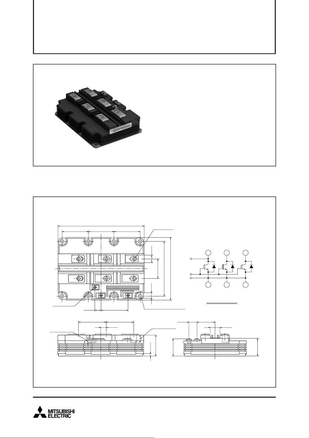
OUTLINE DRAWING & CIRCUIT DIAGRAM Dimensions in mm
190
3-M4 NUTS
screwing depth
min. 7.7
±0.5
57
±0.25
57
±0.25
64 2
53
E
GC
14
±0.3
61.2
±0.5
59.2
12
±0.3
±0.5
61.2
57
±0.5
±0.25
5-M8 NUTS
±0.1
17
±0.25
±0.3
44
1
8-φ7 MOUNTING HOLES
124
±0.1
9
screwing depth
min. 16.5
+1.0
0
±0.15
48
5
±0.5
140
+1.0
(6)
C
(4)
(2)
C
C
C
G
E
E
(5)
CIRCUIT DIAGRAM
18
±0.3
41
±0.5
E
(3)
22
±0.3
E
(1)
LABEL
0
38
±0.3
40.4
HVIGBT (High Voltage Insulated Gate Bipolar Transistor) Modules
May 2009
1
Page 2
3rd-Version HVIGBT (High Voltage Insulated Gate Bipolar Transistor) Modules
MAXIMUM RATINGS
Symbol Item Conditions
j
= –40°C
T
V
V
I
C
I
CM
I
E
IEM
P
V
V
T
T
T
t
psc
CES
GES
c
iso
e
j
op
stg
Collector-emitter voltage
Gate-emitter voltage
Collector current
Emitter current (Note 2)
Maximum power dissipation
(Note 3)
Isolation voltage
Par tial discharge extinction voltage
Junction temperature
Operating temperature
Storage temperature
Maximum short circuit pulse width
VGE = 0V
CE
= 0V, Tj = 25°C
V
DC, T
c
= 80°C
T
j
= +25°C
T
j
= +125°C
Pulse (Note 1)
DC
Pulse (Note 1)
T
c
= 25°C, IGBT part
RMS, sinusoidal, f = 60Hz, t = 1 min.
RMS, sinusoidal, f = 60Hz, Q
CC
= 4500V, VCE ≤ V
V
PD
≤ 10 pC
CES
, VGE = 15V, Tj = 125°C
MITSUBISHI HVIGBT MODULES
CM600HG-130H
HIGH POWER SWITCHING USE
INSULATED TYPE
Ratings Unit
5800
6300
6500
± 20
600
1200
600
1200
8900
10200
5100
–40 ~ +150
–40 ~ +125
–40 ~ +125
10
V
V
A
A
A
A
W
V
V
°C
°C
°C
µs
ELECTRICAL CHARACTERISTICS
Symbol Item Conditions
I
CES
V
GE(th)
I
GES
C
ies
C
oes
C
res
Q
g
V
CE(sat)
t
d(on)
t
r
E
on(10%)
t
d(off)
t
f
t
f2
E
off(10%)
V
EC
t
rr
t
rr2
Q
rr
E
rec(10%)
Collector cutoff current
Gate-emitter threshold voltage
Gate leakage current
Input capacitance
Output capacitance
Reverse transfer capacitance
Total gate charge
Collector-emitter saturation
voltage
Tu r n-on delay time
Tu r n-on rise time
Tu r n-on switching energy
(Note 5)
Tu r n-off delay time
Tu r n-off fall time
Tu r n-off fall time
Tu r n-off switching energy
(Note 5)
Emitter-collector voltage
(Note 2)
Reverse recovery time
(Note 2)
Reverse recovery time
(Note 2)
Reverse recovery charge
(Note 2)
Reverse recovery energy
(Note 2), (Note 5)
V
CE
= V
CES
, VGE = 0V
V
CE
= 10 V, IC = 60 mA, Tj = 25°C
V
GE
= V
GES
, VCE = 0V, Tj = 25°C
CE
= 10 V, VGE = 0 V, f = 100 kHz, Tj = 25°C
V
V
CC
= 3600 V, IC = 600 A, VGE = ±15 V, Tj = 25°C
I
C
= 600 A (Note 4)
V
GE
= 15 V
V
CC
= 3600 V, IC = 600 A, VGE = ±15 V
R
G(on)
= 10 Ω, Tj = 125°C, Ls = 150 nH
t
(IGBT_off)
CC
= 3600 V, IC = 600 A, VGE = ±15 V
V
R
G(off)
= 33 Ω, Tj = 125°C, Ls = 150 nH
= 60 µs
(Note 6)
, Inductive load
Inductive load
I
E
= 600 A (Note 4)
V
GE
= 0 V
CC
= 3600 V, IE = 600 A, VGE = ±15 V
V
R
G(on)
= 10 Ω, Tj = 125°C, Ls = 150 nH
t
(IGBT_off)
= 60 µs
(Note 6)
, Inductive load
j
= 25°C
T
T
j
= 125°C
Tj = 25°C
T
j
= 125°C
Tj = 25°C
T
j
= 125°C
—
—
5.0
–0.5
—
—
—
—
—
—
—
—
—
—
—
—
—
—
—
—
—
Limits
Ty p
—
30
6.0
—
124
7.6
2.2
9.9
4.50
4.60
1.20
0.35
4.50
8.20
0.50
3.10
4.30
4.00
3.60
1.00
2.40
1100
2.00
MaxMin
10
90
7.0
0.5
—
—
—
—
—
—
—
—
—
—
—
—
—
—
—
—
—
—
—
Unit
mA
V
µA
nF
nF
nF
µC
V
µs
µs
J/P
µs
µs
µs
J/P
V
µs
µs
µC
J/P
HVIGBT (High Voltage Insulated Gate Bipolar Transistor) Modules
May 2009
2
Page 3
3rd-Version HVIGBT (High Voltage Insulated Gate Bipolar Transistor) Modules
THERMAL CHARACTERISTICS
Symbol Item Conditions
R
th(j-c)Q
R
th(j-c)R
R
th(c-f)
MECHANICAL CHARACTERISTICS
Symbol Item Conditions
M
t
M
s
M
t
m
CTI
d
a
d
s
L
P CE
R
CC’+EE’
Note 1. Pulse width and repetition rate should be such that junction temperature (Tj) does not exceed T
Thermal resistance
Thermal resistance
Contact thermal resistance
Junction to Case, IGBT part
Junction to Case, FWDi part
Case to Fin, λ
grease
= 1W/m·K, D(c-f) = 100 µm
M8: Main terminals screw
Mounting torque
M6: Mounting screw
M4: Auxiliary terminals screw
Mass
Comparative tracking index
Clearance
Creepage distance
Internal inductance
Internal lead resistance
2. The symbols represent characteristics of the anti-parallel, emitter to collector free-wheel diode (FWDi).
3. Junction temperature (Tj) should not exceed T
4. Pulse width and repetition rate should be such as to cause negligible temperature rise.
5. E
on(10%)
/ E
off(10%)
/ E
rec(10%)
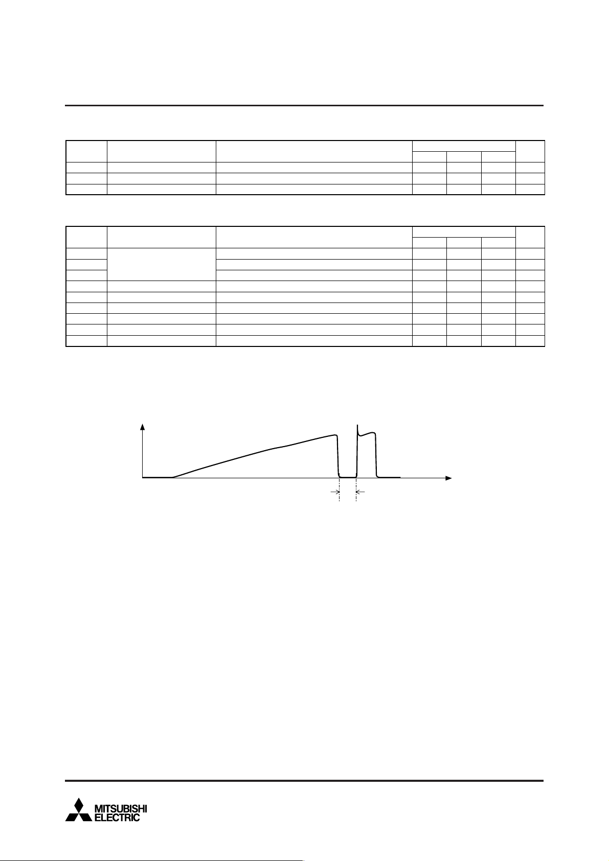
6. t
(IGBT_off)
definition is shown as follows.
are the integral of
T
c
= 25°C
jmax
rating (150°C).
0.1VCE x 0.1IC x dt.
opmax
MITSUBISHI HVIGBT MODULES
CM600HG-130H
HIGH POWER SWITCHING USE
INSULATED TYPE
Limits
rating (125°C).
—
—
—
7.0
3.0
1.0
—
600
26
56
—
—
Ty p
—
—
6.0
Limits
Ty p
—
—
—
1.35
—
—
—
17
0.14
MaxMin
14.0
22.0
—
MaxMin
15.0
6.0
3.0
—
—
—
—
—
—
Unit
K/kW
K/kW
K/kW
Unit
N·m
N·m
N·m
kg
—
mm
mm
nH
mΩ
Ic
time
t(IGBT_off)
HVIGBT (High Voltage Insulated Gate Bipolar Transistor) Modules
May 2009
3
Page 4

3rd-Version HVIGBT (High Voltage Insulated Gate Bipolar Transistor) Modules
90%V
di
10%V
td(off) tf2
0
0
10%V
V
GE
90%I
C
10%V
10%I
C
td(on)
tr
ton
t1 t2 t3 t4
CE
Eon = ic·vce dt
∫
GE
V
CC
I
C
V
CE
t2
t1
MITSUBISHI HVIGBT MODULES
CM600HG-130H
HIGH POWER SWITCHING USE
INSULATED TYPE
GE
90%I
C
50%I
C
10%I
CE
dt
C
t4
Eoff = ic·vce dt
∫
t3
tf = (0.9ic–0.1ic)/(di/dt)
toff = td(off)+tf
Fig. 1 – Definitions of switching times & energies of IGBT part
IE(IF)
di/dt
0
0
di
Irr
trr
dt
10%V
EC
trr2
t5 t60
10%I
VEC(VR)
E
Qrr = – ie dt
Erec = – ie·vec dt
Fig. 2 – Definitions of reverse recovery charge & energy of FWDi part
t6
∫
0
t6
∫
t5
HVIGBT (High Voltage Insulated Gate Bipolar Transistor) Modules
May 2009
4
Page 5

3rd-Version HVIGBT (High Voltage Insulated Gate Bipolar Transistor) Modules
PERFORMANCE CURVES
MITSUBISHI HVIGBT MODULES
CM600HG-130H
HIGH POWER SWITCHING USE
INSULATED TYPE
OUTPUT CHARACTERISTICS
1200
Tj = 125°C
1000
)
A
(
800
600
400
COLLECTOR CURRENT
200
0
0246
COLLECTOR-EMITTER VOLTAGE (V
COLLECTOR-EMITTER SATURATION
VOLTAGE CHARACTERISTICS
1200
V
GE
= 15V
(
TYPICAL
V
GE
= 20V
V
GE
= 15V
V
GE
= 12V
(
TYPICAL
)
)
TRANSFER CHARACTERISTICS
1200
V
CE
= 20V
1000
)
A
(
V
GE
= 10V
V
GE
= 8V
8
)
800
600
400
COLLECTOR CURRENT
200
Tj = 25°C
j
= 125°C
T
0
GATE-EMITTER VOLTAGE (V
FORWARD CHARACTERISTICS
1200
(
TYPICAL
FREE-WHEEL DIODE
(
TYPICAL
)
6 8420 10 12
)
)
1000
)
A
(
800
600
400
COLLECTOR CURRENT
200
Tj = 25°C
j
= 125°C
0
02468
COLLECTOR-EMITTER SATURATION VOLTAGE (V
HVIGBT (High Voltage Insulated Gate Bipolar Transistor) Modules
T
1000
)
A
(
800
600
400
EMITTER CURRENT
200
Tj = 25°C
j
= 125°C
0
02468
)
EMITTER-COLLECTOR VOLTAGE (V
T
)
May 2009
5
Page 6

3rd-Version HVIGBT (High Voltage Insulated Gate Bipolar Transistor) Modules
MITSUBISHI HVIGBT MODULES
CM600HG-130H
HIGH POWER SWITCHING USE
INSULATED TYPE
CAPACITANCE CHARACTERISTICS
3
10
7
5
3
2
2
10
7
)
5
nF
(
3
2
1
10
7
5
3
CAPACITANCE
2
0
10
7
5
3
V
GE
2
f = 100kHz
-1
10
-1
23 57
10
COLLECTOR-EMITTER VOLTAGE (V
HALF-BRIDGE SWITCHING ENERGY
10
V
CC
R
G(on)
Tj = 125°C, Inductive load
8
)
J/P
(
6
(
= 0V, Tj = 25°C
0
10
CHARACTERISTICS
(
= 3600V, V
= 10Ω, R
GE
G(off)
TYPICAL
)
C
ies
C
oes
C
res
23 57 23 57
10
1
)
TYPICAL
)
= ±15V
= 33Ω
E
on
E
off
10
GATE CHARGE CHARACTERISTICS
(
TYPICAL
)
20
V
CE
= 3600V, IC = 600A
Tj = 25°C
15
)
V
(
10
5
0
-5
GATE-EMITTER VOLTAGE
-10
2
-15
GATE CHARGE (µC
151050
)
HALF-BRIDGE SWITCHING ENERGY
CHARACTERISTICS
(
TYPICAL
)
12
V
CC
= 3600V, IC = 600A
V
GE
= ±15V, Tj = 125°C
Inductive load
10
)
J/P
(
8
E
on
4
SWITCHING ENERGIES
2
0
0 500 1000 1500
COLLECTOR CURRENT (A
HVIGBT (High Voltage Insulated Gate Bipolar Transistor) Modules
E
rec
)
6
4
SWITCHING ENERGIES
2
0
6
E
off
E
rec
0204060
GATE RESISTOR (Ω
)
May 2009
80
Page 7

3rd-Version HVIGBT (High Voltage Insulated Gate Bipolar Transistor) Modules
MITSUBISHI HVIGBT MODULES
CM600HG-130H
HIGH POWER SWITCHING USE
INSULATED TYPE
HALF-BRIDGE SWITCHING TIME
2
10
V
CC
= 3600V, V
7
R
G(on)
5
3
2
= 10Ω, R
T
j
= 125°C, Inductive load
)
µs
1
10
(
7
5
3
2
0
10
SWITCHING TIMES
7
5
3
2
-1
10
10
t
f
t
r
1
423 57
COLLECTOR CURRENT (A
CHARACTERISTICS
10
2
(
TYPICAL
GE
G(off)
= ±15V
= 33Ω
)
423 57
10
FREE-WHEEL DIODE REVERSE RECOVERY
CHARACTERISTICS
(
2
10
V
CC
= 3600V, V
7
R
G(on)
5
3
)
2
µs
(
1
t
d(off)
t
d(on)
3
423 57
10
4
10
7
5
3
2
0
10
7
5
REVERSE RECOVERY TIME
3
2
-1
10
10
= 10Ω, R
T
j
= 125°C, Inductive load
1
423 57
)
TYPICAL
GE
G(off)
2
10
EMITTER CURRENT (A
= ±15V
= 33Ω
423 57
)
4
10
7
5
)
A
3
(
10
l
rr
t
rr
3
423 57
10
2
3
10
7
5
3
2
2
10
7
5
REVERSE RECOVERY CURRENT
3
2
1
10
4
)
TRANSIENT THERMAL IMPEDANCE
CHARACTERISTICS
1.2
R
th(j–c)Q
= 14K/kW
R
th(j–c)R
= 22K/kW
1.0
0.8
0.6
0.4
0.2
NORMALIZED TRANSIENT THERMAL IMPEDANCE
0
10
-3
23 57
10
-2
23 57
TIME (s
10
-1
23 57
)
10
0
23 57
10
n
=
th( j –c )
Ri [K/kW]
[sec]
τ
i
( t )
ZR
1
Σ
i=1
0.0059
0.0002
1
1–exp
i
2
0.0978
0.0074
t
–
t
i
3
0.6571
0.0732
4
0.2392
0.4488
HVIGBT (High Voltage Insulated Gate Bipolar Transistor) Modules
May 2009
7
Page 8

3rd-Version HVIGBT (High Voltage Insulated Gate Bipolar Transistor) Modules
REVERSE BIAS SAFE OPERATING AREA
1500
V
CC
≤ 4500V, V
Tj = 125°C, R
G(off)
(
RBSOA
GE
≥ 33Ω
= ±15V
)
15000
V
CC
Tj = 125°C, R
MITSUBISHI HVIGBT MODULES
CM600HG-130H
HIGH POWER SWITCHING USE
INSULATED TYPE
SHORT CIRCUIT
SAFE OPERATING AREA
(SCSOA)
≤ 4500V, V
GE
G(off)
= ±15V
≥ 33Ω
)
A
(
1000
500
COLLECTOR CURRENT
0
0
COLLECTOR-EMITTER VOLTAGE (V
FREE-WHEEL DIODE REVERSE RECOVERY
1500
)
A
(
SAFE OPERATING AREA
(
RRSOA
V
CC
≤ 4500V, di/dt ≤ 3000A/µs
Tj = 125°C
)
)
A
(
10000
5000
COLLECTOR CURRENT
0
)
2000 40000 6000 80002000 4000 6000 8000
COLLECTOR-EMITTER VOLTAGE (V
)
1000
500
REVERSE RECOVERY CURRENT
0
HVIGBT (High Voltage Insulated Gate Bipolar Transistor) Modules
2000 40000 6000 8000
COLLECTOR-EMITTER VOLTAGE (V
)
May 2009
8
 Loading...