

Mitsubishi Electric City Multi PCFY-P15NGMU-E, City Multi PCFY-P24NGMU-E, City Multi PCFY-P30NGMU-E, City Multi PCFY-P36NGMU-E Service Manual

SPLIT-TYPE, HEAT PUMP AIR CONDITIONERS
TECHNICAL & SERVICE MANUAL
August 2006
No. OC343
REVISED EDITION-A
[Models]
PCFY-P15NGMU-E
PCFY-P24NGMU-E
PCFY-P30NGMU-E
PCFY-P36NGMU-E
CONTENTS
1. FEATURES ··········································2
2. PART NAMES AND FUNCTIONS ·······4
3. SPECIFICATIONS ·······························6
4. OUTLINES AND DIMENSIONS···········9
5. WIRING DIAGRAM····························13
6.
7. MICROPROCESSOR CONTROL······15
8. TROUBLE SHOOTING······················22
INDOOR UNIT
9. DISASSEMBLY PROCEDURE··········29
10. PARTS LIST······································33
11. RoHS PARTS LIST ··························40
12. OPTIONAL PARTS ··························47
R410A
REFRIGERANT SYSTEM DIAGRAM
R22
Revision:
• RoHS PARTS LISTis added.
• Some descriptions have been
modified.
• Please void OC343.
NOTE:
• This manual describes only
service data of the indoor
units.
• RoHS compliant products
have <G> mark on the spec
name plate.
• For servicing of RoHS
compliant products, refer to
the RoHS PARTS LIST.
··14
1
Unifies the air speed
with the vane
Sending the air to the upper
area of the vane
Prevents the air comes from
cntering from outside the unit
Protruding portion B
Protruding portion A
Flockless vane
Air outlet
B
A
FEATURES
Indoor unit
Models Cooling capacity / Heating capacity
PCFY-P15NGMU-E 15,000 / 17,000 Btu/h
PCFY-P24NGMU-E 24,000 / 27,000 Btu/h
PCFY-P30NGMU-E 30,000 / 34,000 Btu/h
PCFY-P36NGMU-E 36,000 / 40,000 Btu/h
1. EASY TO CLEAN ; FLOCKLESS VANE
With our original air current control mechanism, a flockless vane is
newly adapted.
The flockless vane prevents the condensation on the vane.
By changing the vane to the flockless type, the unit can be cleaned
much easier with mild household detergent.
2. NEW MATERIALS FOR BETTER OIL RESISTANCE
We have changed the materials of grill, filer, fan and fan casing from ABS to P.P. (polypropylene) for better oil
resistance. As a result, oil crazing is cut in half.
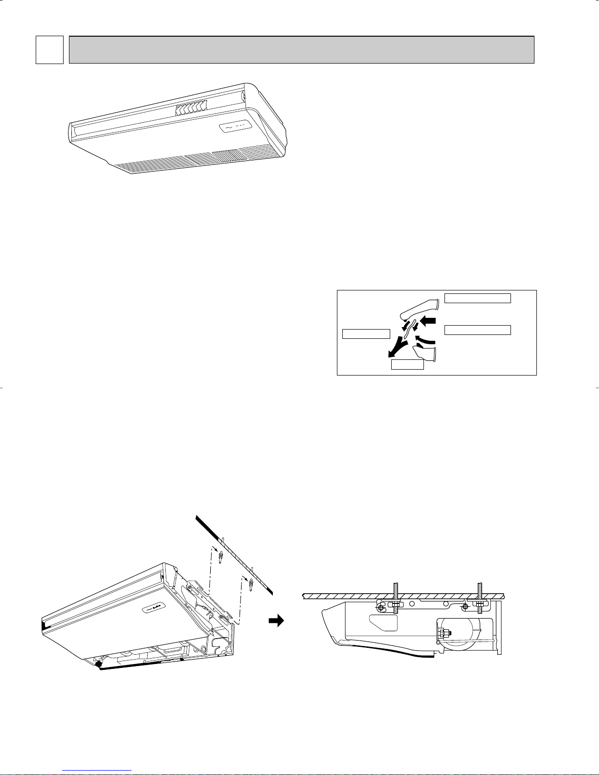
3. SIMPLIFIED INSTALLATION WORK (DIRECT SUSPENDING METHOD)
Simplified the installation work by changing the suspending method to the direct suspending method (suspending
the unit directly from the suspension fixture).
In this way, the unit can be attached to the suspension fixture without removing the installation parts off (Only the
side cover is removed). This method is much simpler than the “One-time installation method”.
2
4. IMPROVING EFFICIENCY OF PIPING WORK
Back panel
U-cut
Side panel
L : Liquid pipe
G : Gas pipe
D : Drain pipe
L
L
G
D
D
G
open
open
11
Removed the knockout work by separating the piping
space from the air outlet for efficiency of the piping work.
22
Improved the flexibility by making it possible for
drainage pipe to exit not only from the right side
back but also from the left side back.
Rubber plug
Insulation cover
(attached)
Drain pipe
(purchased locally)
w Knockout work is needed for the top part. When option-
al drain-up machine is installed, the refrigerant pipe
Drain pan
Joint coupler
(attached)
Insulation
cover
Band
(attached)
w Please move the rubber plug for the unit to the right joint
when drainage pipe exits from the left side.
exits out from the top.
5. EASY MAINTENANCE FILTER ; NO MAINTENANCE NECESSARY FOR 2500 HOURS
The new long-life air filter can be used continuously 2500 hours without maintenance (at general office use).
3
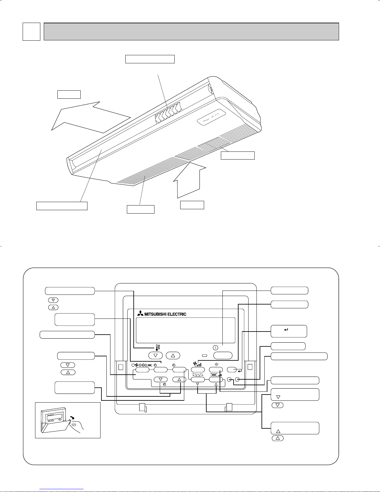
2
Air outlet
Intake grille
Air intake
Left/right guide vanes
Change the direction of airflow
from the horizontal blower.
Long-life filter
Removes dust and foreigh matter from air coming in
through the grille (Recommended cleaning interval :
Approx, every 2,500 operating hours)
Up/down guide vanes
Change the direction of airflow from the
vartical blower.
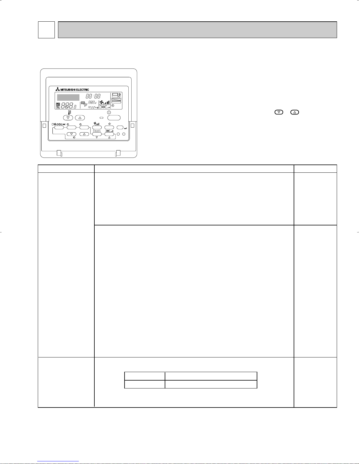
PAR-21MAA
ON/OFF
FILTER
CHECK
OPERATION
CLEAR
TEST
TEMP.
MENU
BACK DAY
MONITOR/SET
CLOCK
ON/OFF
Set Temperature buttons
Down
Up
Timer Menu button
(Monitor/Set button)
Mode button (Return button)
Set Time buttons
Back
Ahead
Timer On/Off button
(Set Day button)
Opening the
door
ON/OFF button
Fan Speed button
Filter button
(<Enter> button)
Test Run button
Check button (Clear button)
Airflow Up/Down button
Louver button
(
Operation button)
To preceding operation
number
Ventilation button
(
Operation button)
To next operation number
PART NAMES AND FUNCTIONS
● Indoor Unit
● Remote controller
● Operation buttons
[PAR-21MAA]
● Once the controls are set, the same operation mode can be repeated
by simply pressing the ON/OFF button.
4
● Display
For purposes of this explanation,
all parts of the display are shown
as lit. During actual operation, only
the relevant items will be lit.
˚F˚C
˚F˚C
ERROR CODE
AFTER
TIMER
TIME SUN MON TUE WED THU FRI SAT
ON
OFF
Hr
AFTER
FILTER
FUNCTION
ONLY1Hr.
WEEKLY
SIMPLE
AUTO OFF
Identifies the current operation
Shows the operating mode, etc.
* Multilanguage display is sup-
ported.
“Centrally Controlled” indicator
Indicates that operation of the remote controller has been prohibited by a master controller.
“Timer Is Off” indicator
Indicates that the timer is off.
Temperature Setting
Shows the target temperature.
Day-of-Week
Shows the current day of the week.
Time/Timer Display
Shows the current time, unless the simple or Auto Off
timer is set.
If the simple or Auto Off timer is set, shows the time
remaining.
“Sensor” indication
Displayed when the remote controller
sensor is used.
“Locked” indicator
Indicates that remote controller buttons have been locked.
“Clean The Filter” indicator
Comes on when it is time to clean the
filter.
Timer indicators
The indicator comes on if the corresponding timer is set.
Up/Down Air Direction indicator
The indicator shows the direction of the outcoming airflow.
“One Hour Only” indicator
Displayed if the airflow is set to
Low and downward during COOL
or DRY mode. (Operation varies
according to model.)
The indicator goes off after one
hour, at which time the airflow
direction also changes.
Room Temperature display
Shows the room temperature.
Louver display
Indicates the action of the swing
louver. Does not appear if the
louver is stationary.
(Power On indicator)
Indicates that the power is on.
Fan Speed indicator
Shows the selected fan speed.
Ventilation indicator
Appears when the unit is running in
Ventilation mode.
Caution
● Only the Power on indicator lights when the unit is stopped and power supplied to the unit.
● If you press a button for a feature that is not installed at the indoor unit, the remote controller will display the “Not Available”
If you are using the remote controller to operate multiple indoor units, this message will appear only if the feature is not
present at every unit connected.
● When power is turned ON for the first time, it is normal that “PLEASE WAIT” is displayed on the room temperature
indication (For max. 2minutes). Please wait until this “PLEASE WAIT” indication disappear then start the operation.
message.
5
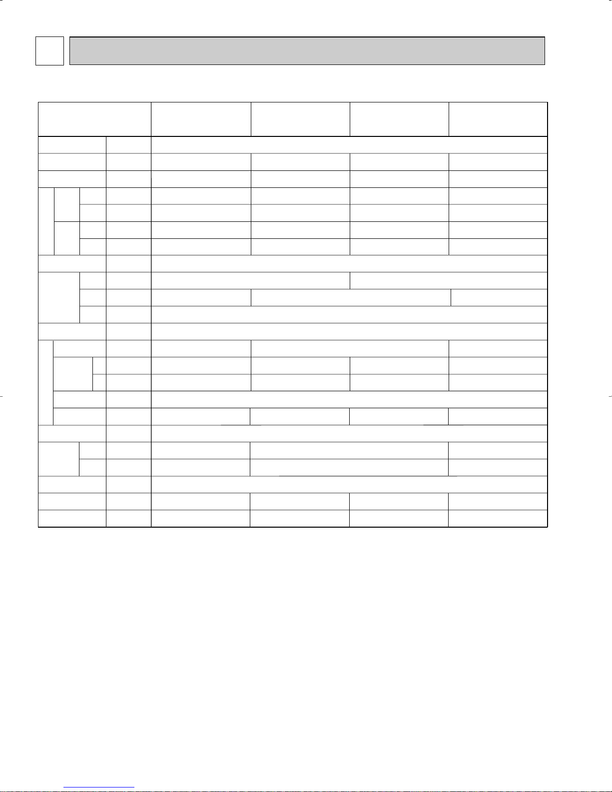
3
Item
V
·Hz
Btu/h
Btu/h
kW
kW
A
A
—
in.
in.
in.
—
—
CFM
CFM
Pa
kW
—
in.
in.
in.
dB
lb
Cooling capacity
Power
Heat exchanger
Air filter
Fan ✕ No
Pipe
dimensions
Unit drain pipe size
Noise level W2
Product weight
Exterior
(munsell symbol)
Fan motor
output
External
static pressure
Liquid
side
Gas
side
Heating capacity
F
a
n
Dimensions
Height
Width
Depth
Electric characteristic
Input
Cooling
Heating
Cooling
Heating
Current
PCFY-P15NGMU-E PCFY-P24NGMU-E PCFY-P30NGMU-E PCFY-P36NGMU-E
Single phase 208/230V 60Hz
15,000
17,000
0.08
0.08
0.40
0.40
24,000
27,000
0.09
0.09
0.45
0.45
30,000
34,000
0.23
0.23
1.12
1.12
36,000
40,000
0.27
0.27
1.32
1.32
420-490-570-640
380-470-530-600
0.07
32-34-37-39
75
Unit : Munsell<0.70Y 8.59/0.97>
51-9/16
26-25/32
Cross fin(Aluminum plate fin and copper tube)
Sirocco fan ✕ 3
0
PP honey comb
5/8"
3/8"
1" I.D. (PVC pipe VP-20 connectable)
5/8" / 3/4"(compatible)
3/8"
8-9/32 10-5/8
640-710-810-880
600-670-770-830
0.09
36-38-41-43
82
63-3/4
Sirocco fan ✕ 4
920-990-1120-1230
870-930-1050-1160
0.15
37-39-42-44
95
39-5/8
Sirocco fan ✕ 2
280-350-390-420
250-310-350-380
0.054
1/2"
1/4"
29-33-36-38
60
DRY
Air flow W2
WET
3-1.
SPECIFICATIONS
SPECIFICATIONS
Note 1. Rating conditions
W 2. Air flow and the noise level are indicated as Low - Medium2 - Medium1 - High.
Cooling : Indoor : D.B. 80_F W.B. 67_F
Heating : Indoor : D.B. 70_F
outdoor : D.B. 95_F W.B. 75_F
outdoor : D.B. 47_F W.B. 43_F
6
3-2. ELECTRICAL PARTS SPECIFICATIONS
Parts name
Model
Symbol
TH21
TH22
TH23
FUSE
MF
C1
MV
LEV
TB2
TB5
TB15
250V 6A
OFF 266˚F ±41˚F
(L1, L2, GR) 330V 30A
(M1, M2, S) 250V 20A
(1, 2) 250V 10A
3µF ✕ 440V
Inner-thermostat
4µF ✕ 440V 5µF ✕ 440V 7µF ✕ 440VFan motor capacitor
Vane motor
Linear expansion valve
PCFY-P15NGMU-E PCFY-P24NGMU-E PCFY-P30NGMU-E PCFY-P36NGMU-E
Room temperature
thermistor
Liquid pipe temperature
thermistor
Gas pipe temperature
thermistor
Fuse
(Indoor controller board)
Fan motor
(with inner-thermostat)
Power supply
terminal block
Transmission
terminal block
MA remote controller
terminal block
DC12V Stepping motor drive
port [3.2 (0~2000pulse) EDM-40YGME
4-Pole Output 54W
D09B4P54MS
MP35EA
DC12V
MP42EA
DC12V
4-Pole Output 70W
D09C4P70MS
4-Pole Output 90W
D10C4P90MS
4-Pole Output 150W
D10D4P150MS
DC12V Stepping motor drive
port [5.2 (0~2000pulse) EDM-80YGME
Resistance 30_F/15.8k", 50_F/9.6k", 70_F/6.0k", 80_F/4.8k", 90_F/3.9k", 100_F/3.2k"
Resistance 30_F/15.8k", 50_F/9.6k", 70_F/6.0k", 80_F/4.8k", 90_F/3.9k", 100_F/3.2k"
Resistance 30_F/15.8k", 50_F/9.6k", 70_F/6.0k", 80_F/4.8k", 90_F/3.9k", 100_F/3.2k"
7
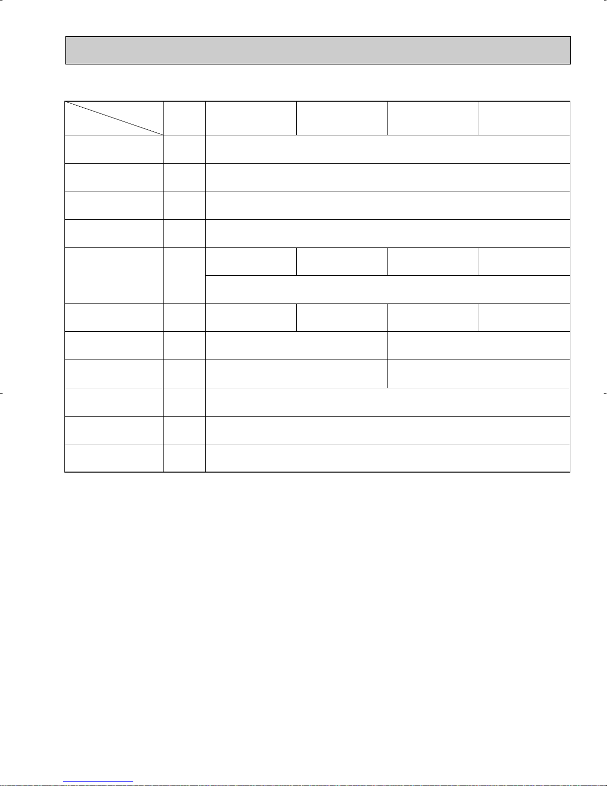
3-3. NOISE CRITERION CURVES
90
80
70
60
50
40
30
20
10
63 125 250 500 1000 2000 4000 8000
APPROXIMATE THRESHOLD OF HEARING
FOR CONTINUOUS NOISE
NC-60
NC-50
NC-40
NC-30
NC-20
NC-70
OCTAVE BAND SOUND PRESSURE LEVEL, dB (0 dB = 0.0002 µbar)
BAND CENTER FREQUENCIES, Hz
PCFY-P15NGMU-E
High
NOTCH
Medium1
Medium2
Low
38
SPL(dB)
36
33
29
LINE
90
80
70
60
50
40
30
20
10
63 125 250 500 1000 2000 4000 8000
APPROXIMATE
THRESHOLD OF
HEARING FOR
CONTINUOUS
NOISE
NC-60
NC-50
NC-40
NC-30
NC-20
NC-70
OCTAVE BAND SOUND PRESSURE LEVEL, dB (0 dB = 0.0002 µbar)
BAND CENTER FREQUENCIES, Hz
PCFY-P24NGMU-E
High
NOTCH
Medium1
Medium2
Low
39
SPL(dB)
37
34
32
LINE
90
80
70
60
50
40
30
20
10
63 125 250 500 1000 2000 4000 8000
APPROXIMATE
THRESHOLD OF
HEARING FOR
CONTINUOUS
NOISE
NC-60
NC-50
NC-40
NC-30
NC-20
NC-70
OCTAVE BAND SOUND PRESSURE LEVEL, dB (0 dB = 0.0002 µbar)
BAND CENTER FREQUENCIES, Hz
PCFY-P30NGMU-E
High
NOTCH
Medium1
Medium2
Low
43
SPL(dB)
41
38
36
LINE
90
80
70
60
50
40
30
20
10
63 125 250 500 1000 2000 4000 8000
APPROXIMATE
THRESHOLD OF
HEARING FOR
CONTINUOUS
NOISE
NC-60
NC-50
NC-40
NC-30
NC-20
NC-70
OCTAVE BAND SOUND PRESSURE LEVEL, dB (0 dB = 0.0002 µbar)
BAND CENTER FREQUENCIES, Hz
PCFY-P36NGMU-E
High
NOTCH
Medium1
Medium2
Low
44
SPL(dB)
42
39
37
LINE
UNIT
About 1.4m
MICROPHONE
CEILING
1m
1m
8
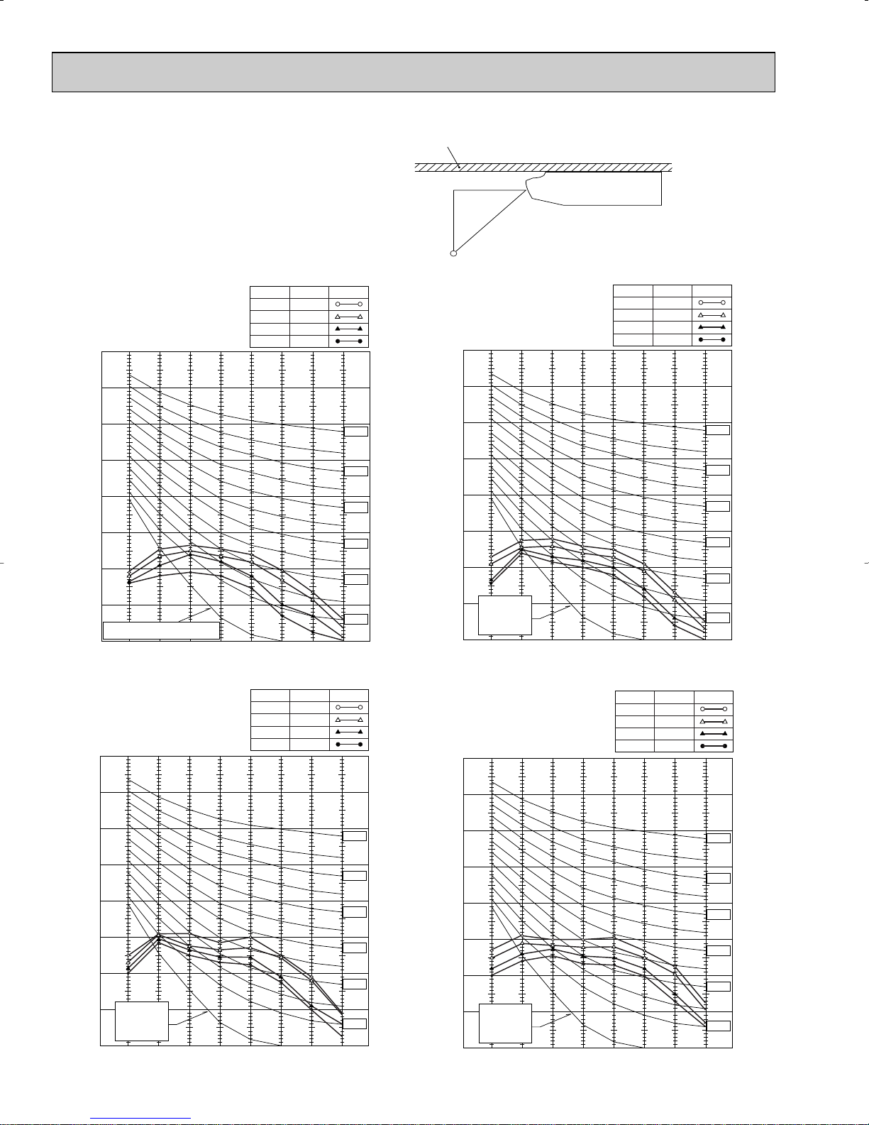
4
9
2-7/16(62) 1-15/16(49)
1-3/4(45)
11-13/16(300)
7/16(11)
Knock out hole for fresh air intake
9
1-1/4(32)6-11/32(161)
(7~8)
1/4~9/32
1-21/32(42) 7-1/16(179)
3-1/8(79)
1-1/2(38)1-1/2(38)
5-5/32(131)
(175)
1-13/16(46)
6-7/8 1/16(1)
3-11/16(86)
5-7/16(138)
6-3/4(171)
10-3/8(263)
13-7/8(352)20-21/32(525)
36-17/32(928)
2-3/4(70)
9-1/32(229)
(150)
23/32(18)
5-29/32
5-1/2(140) 2-3/4(70)
3-1/8(80)12-5/8(320)
3-7/16(87)
5/8(16)
6-3/16(157)
9-1/2(241)
7-15/16(201)
7-3/16(182)
Less than
26-25/32(680)
9-13/16(230)
39-3/8(1000)
11-13/16(300)
10-5/8(270)
or more
6
Allowing clearances
Less than
1/16(1)
(Gap to ceiling)
19-11/16(500)
or more
or more
Ceiling
Rear wall
10(254)
19-29/32(506)
2-7/32(56)
26-25/32(680)
36-5/32(918)
3-17/32(90)6-3/8(161)
Air intake
liquid 1/4F([6.35)
gas 1/2F([12.7)
(Drainage)
38-11/16(983)
3-25/32(96)
7-3/32(180)
8-9/32(210)
3-3/16(81)
39-5/8(1000)
35-19/32(904)
Air outlet
36-23/32(933)
(Suspension bolt pitch)
4
5
8
1
(FRONT VIEW)
2
Electrical box
3
2
7
Electrical box
When electrical box
is pulled down
Ceiling
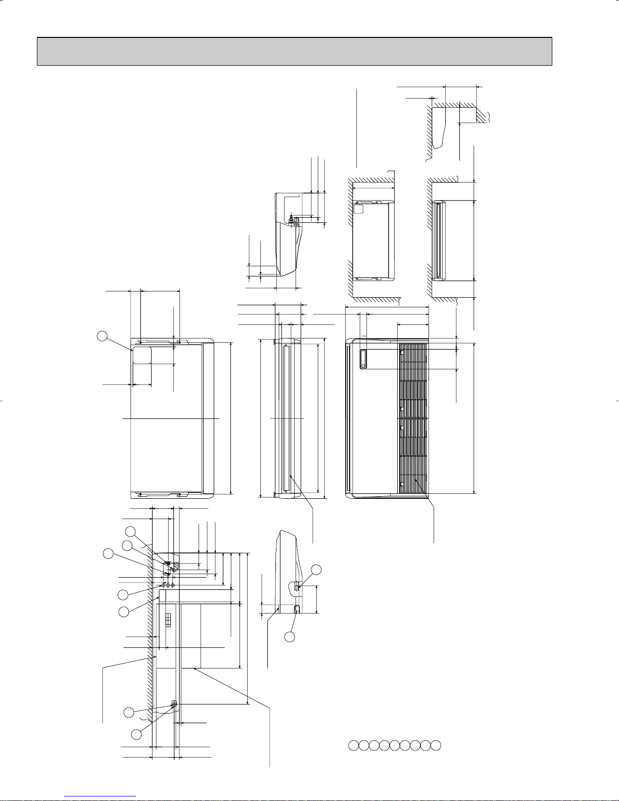
Refrigerant-pipe connection(liquid pipe side/flared connection)
Knock out hole for upper pipe arrangement
Knock out hole for left drain pipe arrangement
Knock out hole for wiring arrangement
Drainage pipe connection(1-1/32(26mm)I.D.)
Drainage pipe connection(for the left arrangement)
Knock out hole for left drain-piping arrangement
Refrigerant-pipe connection(gas pipe side/flared connection)
1234567
8
NOTES.
1.Use M10 or W3/8 screw for anchor bolt.
2.Please be sure when installing the drain-up machine
(option parts),refrigerant pipe will be only
upper drain pipe arrangement.
OUTLINES AND DIMENSIONS
INDOOR UNIT
PCFY-P15NGMU-E
Unit: in.(mm)
9
PCFY-P24NGMU-E
or more
19-11/16(500)
(Gap to ceiling)
1/16(1)
Unit : in.(mm)
5/8(16)
3-7/16(87)
NOTES.
1.Use M10 or W3/8 screw for anchor bolt.
2.Please be sure when installing the drain-up machine
(option parts),refrigerant pipe will be only
upper drain pipe arrangement.
12-5/8(320) 3-1/8(80)
2-3/4(70)
6-3/16(157)
8-9/32(210)
7-3/32(180)
6
(150)
23/32(18)
5-29/32
5-1/2(140)
(Suspension bolt pitch)
50-13/16(1290)
gas 5/8F([15.88)
liquid 3/8F([9.52)
9-1/2(241)
7-3/16(182)
7/15/16(201)
51-9/16(1310)
47-13/16(1214)
(Drainage)
Allowing clearances
26-25/32(680)
Less than
Rear wall
2-7/32(56)19-29/32(506)
2-3/16(81) 3-25/32(96)
Ceiling
26-25/32(680)
10(254)
Less than
9-13/16(250)
3-17/32(90)6-3/8(161)
or more
or more
48-3/8(1228) 11-13/16(300)51-9/16(1310)10-5/8(270)
1/16(1)
5-5/32(131)
(175)
6-7/8
1-13/16(46)
4
1
5
1-1/2(38)
3-1/8(79)
3-3/8(86)
5-7/16(138)
1-1/2(38)
8
9
Ceiling
(FRONT VIEW)
Electrical box
7/16(11)
2
(6~7)
1/4~9/32
3
1-1/4(32)6-11/32(161)
6-3/4(171)
1-21/32(42) 7-1/16(179)
48-13/16(1240)
10-3/8(263)
11-13/16(300)
16-3/8(416)
3-15/16(100)
2-1/8(54) 2-1/4(57)
20-21/32(525)
2-3/4(70)
48-5/8(1235)
7
Electrical box
When electrical box
is pulled down
10
Air outlet
2
9-1/32(229)
Air intake
Drainage pipe connection(1-1/32(26mm)I.D.)
Drainage pipe connection(for the left arrangement)
Refrigerant-pipe connection(liquid pipe side/flared connection)
Knock out hole for left drain-piping arrangement
Refrigerant-pipe connection(gas pipe side/flared connection)
1234567
Knock out hole for fresh air intake
Knock out hole for upper pipe arrangement
Knock out hole for left drain pipe arrangement
Knock out hole for wiring arrangement
9
8
PCFY-P30NGMU-E
NOTES.
1.Use M10 or W3/8 screw for anchor bolt.
2.Please be sure when installing the drain-up machine
(option parts),refrigerant pipe will be only
upper drain pipe arrangement.
6
12-5/8(320) 3-1/8(80)
2-3/4(70)5-1/2(140)
5/8(16)
3-7/16(87)
gas 5/8F([15.88)
liquid 3/8F([9.52)
7-3/16(182)
7-13/16(198)
8-17/32(217)
Allowing clearances
(Drainage)
9-5/8(245)
Rear wall
10-5/8(270)
(56)
8-5/32(207)
2-7/32
3-3/16(81) 3-25/32(96)
Less than
26-25/32(680)
26-25/32(680)
19-29/32(506)
10(254)
(Gap to ceiling)
1/16(1)
19-11/16(500)
Ceiling
3-17/32(90)6-3/8(160)
Less than
9-13/16(250)
(300)
or more
11-13/16
51-9/16(1310)
or more
10-5/8(270)
Unit: in.(mm)
23/32(18)5-29/32(150)
9-9/32(236)
(196)
1/16(1)
4
1
5
8
7-9/16
3-3/8(86)
5-1/2(140)
1-1/2(38)
9
7/16(11)
2-3/16(55)5-7/8(150)
(FRONT VIEW)
Ceiling
3-21/32(93)
(6~7)
1/4~9/32
Electrical box
2
3
(160)
6-5/16
7-2/32(289)1-21/32(42)
1-25/32(45)
6-3/4(171)
5-7/16(138)
1-1/2(38)
(Suspension bolt pitch)
48-13/16(1240)
13(330)
10-3/8(263)
27-1/16(687)20-21/32(525)
7-7/8(200)
48-5/8(1235)
When electrical
box is pulled
down
50-13/16(1290)
2-3/4(70)
Electrical box
11
7
51-9/16(1310)
47-13/16(1214)
Air outlet
2
9-1/32(229)
48-3/8(1228)
Air intake
Refrigerant-pipe connection(liquid pipe side/flared connection)
Drainage pipe connection(1-1/32(26mm)I.D.)
Drainage pipe connection(for the left arrangement)
Knock out hole for left drain-piping arrangement
3
2
1
Knock out hole for upper pipe arrangement
Refrigerant-pipe connection(gas pipe side/flared connection)
6
5
4
Knock out hole for fresh air intake
Knock out hole for left drain pipe arrangement
Knock out hole for wiring arrangement
9
8
7
RG01N982
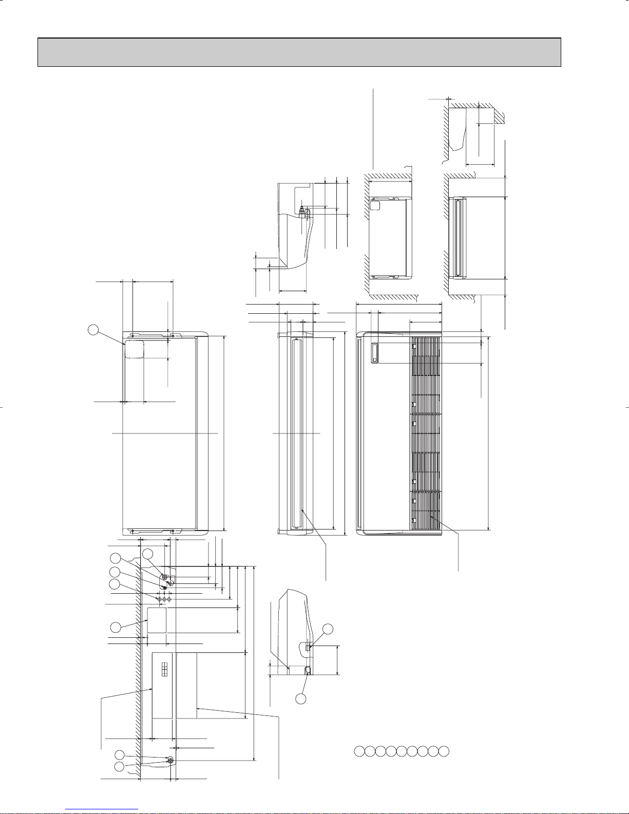
PCFY-P36NGMU-E
9
7-7/8(200) 13(330)
5-7/8(150) 2-3/16(55)
7/16(11)
When electrical box
is pulled down
9
Knock out hole for fresh air intake
1-21/32(42)
Electrical box
3-21/32(93)6-5/16(160)
1/4~9/32(6~7)
1/16(1)1-25/32(45) 9-9/32(236)
7-9/16(192)
1-1/2(38) 1-1/2(38)
5-1/2(140)
10-3/8(263)
6-3/4(171)
5-7/16(138)
3-3/8(86)
27-1/16(687)
20-21/32(525)
60-13/16(1545)
9-1/32(229)
2-7/32(56)19-29/32(506)
10(254)
26-25/32(680)
3-3/16(81) 3-25/32(96)
8-5/32(207)
10-5/8(270)
60(1524)
63-3/4(1620)
23/32(18)5-29/32(150)
2-3/4(70)5-1/2(140)
12-5/8(320) 3-1/8(80)
3-7/16(87)
5/8(16)
8-17/32(217)
9-5/8(245)
7-13/16(198)
7-3/16(182)
liquid 3/8F([9.52)
(Drainage)
gas 5/8F/3/4F(Compatible)
([15.88/[19.05)
Less than
26-25/32(680)
10-5/8(270) 11-13/16(300)63-3/8(1620)
or more
1/16(1)
19-11/16(500)
9-13/16(250)
Refrigerant-pipe connection(liquid pipe side/flared connection)
Knock out hole for upper pipe arrangement
Knock out hole for left drain pipe arrangement
Knock out hole for wiring arrangement
1234567
8
Drainage pipe connection(1-1/32(26mm)I.D.)
Drainage pipe connection(for the left arrangement)
Knock out hole for left drain-piping arrangement
Refrigerant-pipe connection(gas pipe side/flared connection)
6
4
8
5
1
3
2
Electrical box
2
7
Air outlet
Air intake
or more
or more
Less than
Ceiling
(FRONT VIEW)
(Suspension bolt pitch)
Allowing clearances
Rear wall
Ceiling
(Gap to ceiling)
NOTES.
1.Use M10 or W3/8 screw for anchor bolt.
2.Please be sure when installing the drain-up machine
(option parts),refrigerant pipe will be only
upper drain pipe arrangement.
7-1/16(239)
2-3/4(70)
60-7/16(1535)
60-29/32(1547)
6-3/8(161) 3-17/32(90)
PCFY-P36NGMU-E
Unit : in.(mm)
12
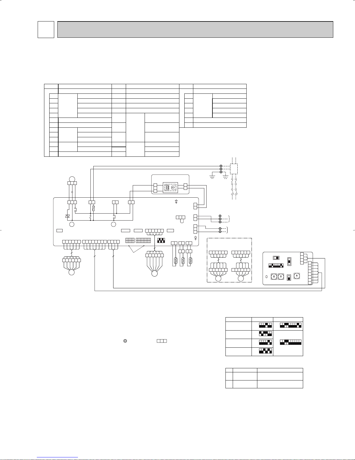
PCFY-P15NGMU-E PCFY-P24NGMU-E PCFY-P30NGMU-E PCFY-P36NGMU-E
MF
654321 87654321 4321
654321
654321
21 21 21
SW2
(GRN)
VANE
CN6V
(RED)
ADDRESS
CN81
(RED)
ADDRESS
CN42
FUSE
250V
6A
(GRN)
REMOTE
INDICATION
CN52
(WHT)
CENTRALLY
CONTROL
CN51
(WHT)
REMOTO
SWITCH
CN32
(WHT)
LEV
CN60
See fig:w 1
ON
OFF
X1
X4
ZNR
F.C
ON
OFF
SW3 SW4
6
ORN
BLU
WHT
YLW
BRN
RED
654321
12345678910123456 12345
3
2
1
2
1
1
2
1
2
1
2
3
(YLW)
HEATER
CN24
135
135
13 13 13
321
MV
654321
654321
MV
654321
654321
MV
TH21 TH22 TH23
21 21
L1
L2
GR
X4 X1
M1
M2
1
2
8
7
6
5
4
3
2
1
4
3
2
1
48
6
5151 13
(WHT)
DRAIN
CN31
AC208-230V
(RED)
CNSK
DC13.1V
(WHT)
CN2S
(WHT)
LIQUID
CN21
(RED)
INTAKE
CN20
(BLK)
GAS
CN29
(GRN)
VAHE
CN6V
(GRN)
VAHE
CN6V
CN2D
(WHT)
CN3A
(BLU)
CN2M
(BLU)
M-NET
LED1
TRANS
BLU
BLU
BLU
BLK
WHT
ORN
ORN
RED
LED2
CNDK
(RED)
CNP
(BLU)
FAN
(WHT)
CND
(RED)
BLK
BLK
BLU
RED
RED
WHT
WHT
C1
I.B
P.B
TB2
PULL BOX
FUSE(15A)
BREAKER
(15A)
TO NEXT INDDOR UNIT
GRN
/
YLW
POWER SUPPLY
~/N 208-230V 60Hz
TB5
S(SHIELD)
TO OUTDOOR UNIT
BC CONTROLLER
REMOTE CONTROLLER
DC24-30V
TO MA-REMOTE
CONTROLLER
DC8.7-13V
TB15
MODEL
PCFY-P30NGMU-E
MODEL
PCFY-P36NGMU-E
65
BLU
WHT
YLW
ORN
RED
RED
BRN
BLU
WHT
YLW
ORN
A.B
208V 230V
SW5
SW1
SW12
2ND
DIGIT
3RD
DIGIT
SWA
SWC
3
2
1
0
SW11
1ST
DIGIT
0
SW14
CONNECTION
NO.
0
(RED)
ADDRESS
CN43
(RED)
ADDRESS
CN82
ON
OFF
12345678910
ORN
BLU
WHT
YLW
BRN
RED
LEV
PCFY-P15NGMU-E
PCFY-P24NGMU-E
PCFY-P30NGMU-E
PCFY-P36NGMU-E
Models SW2<w1> SW3
ON
OFF
123456
ON
OFF
12345678910
ON
OFF
12345678910
ON
OFF
123456
ON
OFF
123456
ON
OFF
123456
<w2>
Use Copper Supply Wire.
w 2
1
2
Symbol
I. B
Connector Heater
Remote switch
Centrally control
Remote indication
Drain-up machine
Fan phase control
FUSE (6A/250V)
Switch Capacity code
Mode selection
Model selection
Aux.Relay Drain-up machine
Fan motor
Varistor
INDOOR POWER BOARD
Capacitor (fan motor)
Linear expansion valve
Fan motor (with inner thermo)
Vane motor
Thermistor Room temp, detection
(
32°F/15k", 77°F/5.4k"
)
Pipe temp, detection/Iiguid
(
32°F/15k", 77°F/5.4k"
)
Pipe temp, detection/Gas
(
32°F/15k", 77°F/5.4k"
)
Terminal Power supply
block Transmission
MA-remote controller
Legend
Name Symbol Name
P. B
C1
LEV
MF
MV
TH21
TH22
TH23
TB2
TB5
TB15
Indoor controller board
CN24
CN32
CN51
CN52
CNP
F.C
FUSE
SW2
SW3
SW4
X1
X4
ZNR
Symbol
A. B
Switch Mode selection
Voltage selection
Address setting 1st digit
Address setting 2nd digit
Connection No.
Ceiling height Selector
Option Selector
Name
Circuit board Address
SW1
SW5
SW11
SW12
SW14
SWA
SWC
LED on indoor board for service
Meaning
Mark
Main power supply
Power supply for
MA-Remote controller
Main power supply(Indoor unit:208-230V)
power on➝Iamp is Iit
Power supply for MA-Remote controller
on➝Iamp is lit
Function
LED1
LED2
Note
1.At servicing for outdoor unit, always follow the wiring diagram of outdoor unit.
2.In case of using MA-Remote controller, please connect to TB15.
(Remote controller wire is non-polar.)
3.In case of using M-NET, please connect to TB5. (Transmission line is non-polar.)
4.Symbol [S] of TB5 is the shield wire connection.
5.Symbols used in wiring diagram above are, : terminal block, : connector.
6.The setting of the SW2/SW3 dip switches differs in the capacity.
For the detail, refer to the fig:
w
1.
7.Please set the switch SW5 according to the power supply voltage.
Set SW5 to 230V side when the power supply is 230 volts.
When the power supply is 208 volts, set SW5 to 208V side.
5
WIRING DIAGRAM
13
6
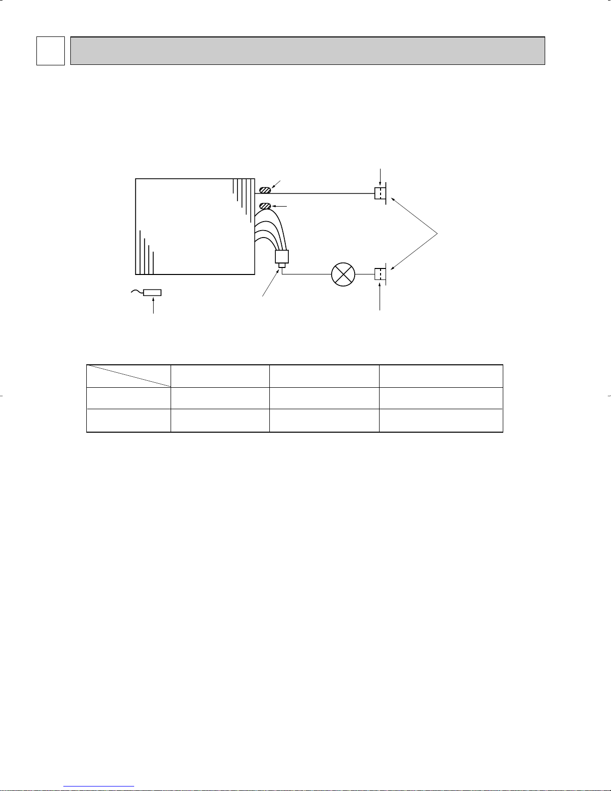
REFRIGERANT SYSTEM DIAGRAM
PCFY-P15NGMU-E
PCFY-P24NGMU-E
PCFY-P30NGMU-E
PCFY-P36NGMU-E
Item
Gas pipe
Liquid pipe
Heat exchanger
Strainer (# 50mesh)
Room temperature thermistor TH21
Model
PCFY-P15NGMU-E
{12.7(1/2”)
{6.35(1/4”)
Gas pipe temperature
thermistor TH23
Liquid pipe temperature
thermistor TH22
Linear expansion valve
PCFYP24/P30NGMU-E
{15.88(5/8”)
{9.52(3/8”)
Strainer (#100mesh)
Gas pipe
Flare connection
Liquid pipe
Strainer (#100mesh)
Unit : mm(in.)
PCFY-P36NGMU-E
{15.88(5/8”)/{19.05(3/4”)
(compatible)
{9.52(3/8”)
14
MICROPROCESSOR CONTROL7
PAR-21MAA
ON/OFF
FILTER
CHECK
OPERATION
CLEAR
TEST
TEMP.
MENU
BACK DAY
MONITOR/SET
CLOCK
ON/OFF
˚F˚C
˚F˚C
ERROR CODE
AFTER
TIMER
TIME SUN MON TUE WED THU FRI SAT
ON
OFFHrAFTER
FILTER
FUNCTION
ONLY1Hr.
WEEKLY
SIMPLE
AUTO OFF
Control modes
Control details
1-1. Thermoregulating function (Function to prevent restarting for 3 minutes)
• Room temperature ] desired temperature + 2°F
···Thermo ON
• Room temperature [ desired temperature
···Thermo OFF
1-2. Frozen prevention control
Detected condition : When the liquid pipe temp. (TH22) is 32°F or less in 16
minutes from compressor start up, anti-freezing control
starts and the thermo OFF.
Released condition : The timer which prevents reactivating is set for 3 minutes,
and anti- freezing control is cancelled when any one of the
following conditions is satisfied.
1 Liquid pipe temp. (TH22) turns to be 50°F or above.
2 The condition of the thermo OFF become complete
by thermoregulating, etc.
3 The operation modes become mode other than COOL.
4 The operation stops.
By the remote controller setting (switch of 4 speeds)
2. Fan
1. Thermoregulating
function
Remarks
Type
Fan speed notch
[Low], [Med2], [Med1], [High]
4 speeds
To be continued to the next page
INDOOR UNIT CONTROL
7-1. COOL OPERATION
<How to operate>
1 Press POWER ON/OFF button.
2 Press the operation MODE button to display COOL.
3 Press the TEMP. button to set the desired temperature.
NOTE: The set temperature changes 2°F when the or button is
pressed one time Cooling 67 to 87°F.
15
 Loading...