

Mitsubishi Electric CITY MULTI PAC-YT52CRA, Simple MA PAC-YT52CRA Installation Manual
– 1 –
GB
This installation manual describes how to install the Simple MA Remote Controller for use with
Mitsubishi Building Air Conditioning System, direct expansion type CITY MULTI air conditioner indoor
units (“-A” type and later), and Mitsubishi Mr. SLIM packaged air conditioners.
Please be sure to read this installation manual and Instruction Book that are supplied with the Remote
Controller before proceeding with the installation. Failure to follow the instructions may result in
equipment damage.
For information on how to wire and install the air conditioning units, refer to the installation manual.
After the installation, hand over this manual to users.
• Read the following safety precautions prior to installation.
• Observe these precautions carefully to ensure safety.
• After reading this manual, provide this manual to end user for future reference.
• Keep this manual for future reference and refer to it as necessary. This manual should be made
available to those who repair or relocate the controller. Make sure that the manual is forwarded to
future end users.
WARNING
1 Safety Precautions
WARNING
Indicates a risk of death or serious injury if you misuse the PAC-YT52CRA.
CAUTION
Indicates a risk of serious injury or structural damage if you misuse the
PAC-YT52CRA.
General precautions
All electric work must be performed by qualified personnel.
Do not install the unit in a place where large amounts of
oil, steam, organic solvents, or corrosive gases, such
as sulfuric gas, are present or where acidic/alkaline
solutions or sprays are used frequently. These
substances can compromise the performance of the
unit or cause certain components of the unit to corrode,
which can result in electric shock, malfunctions,
smoke, or fire.
To reduce the risk of shorting, current leakage, electric
shock, malfunctions, smoke, or fire, do not wash the
controller with water or any other liquid.
To reduce the risk of electric shock, malfunctions,
smoke or fire, do not operate the switches/buttons or
touch other electrical parts with wet hands.
To reduce the risk of injury or electric shock, stop the
operation and switch off the power supply before
cleaning, maintaining, or inspecting the controller.
To reduce the risk of injury or electric shock, before
spraying a chemical around the controller, stop the
operation and cover the controller.
To reduce the risk of injury, keep children away while
installing, inspecting, or repairing the unit.
Properly install all required covers to keep moisture
and dust out of the controller. Dust accumulation and
water can cause electric shock, smoke, or fire.
CITY MULTI Control System
and Mitsubishi Mr. SLIM Air Conditioners
Simple MA Remote Controller PAC-YT52CRA
Installation Manual
WT06592X01
GB
For distribution to dealers and contractors
DFESINLPRGRRUTRSCTCDESW
– 2 –
GB
CAUTION
WARNING
CAUTION
WARNING
CAUTION
Precautions during installation
Precautions during wiring
To reduce the risk of electric shock or malfunctions, do
not touch the touch panel, switches, or buttons with a
pointy or sharp object.
To reduce the risk of damage to the controller, do not
directly spray insecticide or other flammable sprays on
the controller.
To reduce the risk of injury and electric shock, avoid
contact with sharp edges of certain parts.
To reduce the risk of injury, wear protective gear when
working on the controller.
Consult your dealer for the proper disposal of the
controller.
Do not install the unit where there is a risk of leaking
flammable gas.
If flammable gas accumulates around the unit, it may
ignite and cause a fire or explosion.
To reduce the risk of shorting, current leakage, electric
shock, malfunctions, smoke, or fire, do not install the
controller in a place exposed to water or in a
condensing environment.
Controller must be installed by qualified personnel
according to the instructions detailed in the Installation
Manual.
Improper installation may result in electric shock or fire.
Install the top case into the bottom case until it clicks.
To reduce the risk of damage to the controller,
malfunctions, smoke, or fire, do not connect the power
cable to the signal terminal block.
Properly secure the cables in place and provide
adequate slack in the cables so as not to stress the
terminals. Improperly connected cables may break,
overheat, and cause smoke or fire.
To reduce the risk of injury or electric shock, switch off
the main power before performing electrical work.
All electric work must be performed by a qualified
electrician according to the local regulations,
standards, and the instructions detailed in the
Installation Manual.
To reduce the risk of electric shock, install a breaker
and a residual current circuit breaker on the power
supply.
To reduce the risk of electric shock, smoke, or fire,
install a breaker for each controller.
Use properly rated breakers and fuses (breaker, local
switch <switch + fuse>, no-fuse breaker).
Breaker with a breaking capacity greater than the
specified capacity may cause electric shock,
malfunctions, smoke, or fire.
To reduce the risk of current leakage, overheating,
smoke, or fire, use properly rated cables with adequate
current carrying capacity.
Proper grounding must be provided by a licensed
electrician.
Do not connect the grounding wire to a gas pipe, water
pipe, lightning rod, or telephone wire.
Improper grounding may result in electric shock,
smoke, fire, or malfunction due to electrical noise
interference.
To reduce the risk of electric shock, shorting, or
malfunctions, keep wire pieces and sheath shavings
out of the terminal block.
To reduce the risk of shorting, current leakage, electric
shock, or malfunctions, keep the cables out of contact
with controller edges.
To reduce the risk of electric shock, malfunctions, or
fire, seal the gap between the cables and cable access
holes with putty.
– 3 –
GB
WARNING
CAUTION
Precautions for moving or repairing the controller
Additional precautions
The controller should be repaired or moved only by
qualified personnel.
Do not disassemble or modify the controller.
Improper installation or repair may cause injury, electric
shock, or fire.
To reduce the risk of electric shock, shorting, or
malfunctions, keep wire pieces and sheath shavings
out of the terminal block.
To avoid damage to the unit, use appropriate tools to
install, inspect, or repair the unit.
This controller is designed for exclusive use with the
Building Management System by Mitsubishi Electric.
The use of this controller for with other systems or for
other purposes may cause malfunctions.
To avoid discoloration, do not use benzene, thinner, or
chemical rag to clean the controller.
To clean the controller, wipe with a soft cloth soaked in
water with mild detergent, wipe off the detergent with a
wet cloth, and wipe off water with a dry cloth.
To avoid damage to the controller, provide protection
against static electricity.
Take appropriate measures against electrical noise
interference when installing the air conditioners in
hospitals or facilities with radio communication
capabilities.
Inverter, high-frequency medical, or wireless
communication equipment as well as power
generators may cause the air conditioning system to
malfunction. Air conditioning system may also
adversely affect the operation of these types of
equipment by creating electrical noise.
To avoid malfunctions, do not bundle power cables and
signal cables together, or place them in the same
metallic conduit.
Leave the circuit board and its protective film on the
case.
To avoid damage to the controller, do not overtighten
the screws.
Use a flat-head screwdriver with a blade width of 5 mm
(7/32 inch).
Do not turn the flat-head screwdriver with fitting it in the
latch strongly.
To avoid deformation and malfunction, do not install
the remote controller in direct sunlight or where the
ambient temperature may exceed 40ºC (104ºF) or
drop below 0ºC (32ºF).
Do not install the controller on the control panel door.
Vibrations or shocks to the controller may damage the
controller or cause the controller to fall.
Secure the cable with a clamp.
Do not use solderless terminals to connect cables to
the terminal block.
Solderless terminals may come in contact with the
circuit board and cause malfunctions or damage the
controller cover.
After connecting the connector, install the top case
properly.
– 4 –
GB
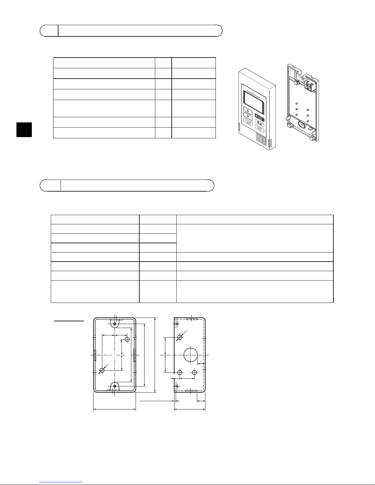
The following parts are included in the box.
(1) Field-supplied parts
The following parts are field-supplied parts.
(2) Field-supplied tools
• Flat-tip screwdriver (Width: 3 - 5 mm (1/8 - 7/32 inch))
• Knife or Nipper
• Miscellaneous tools
2 Component names and supplied parts
*3 ISO metric screw thread
*4 Remote controller cable is not included.
3 Field-supplied parts/Required tools
Parts name Qty. Notes
Single switch box 1 Not required for direct wall installation
Thin metal conduit Necessary
Lock nut and bushing Necessary
Cable cover Necessary Required for routing remote controller cable along a wall
Putty Reasonable
Molly anchor Necessary
Remote controller cable
(Use a 0.3 mm² (AWG22) 2-core
sheathed cable.)
Necessary
Parts name Qty. Appearance
Remote controller (top case) 1 Right figure *1
Remote controller (bottom case) 1 Right figure *2
Roundhead cross slot screws M4×30 2 *3
Wood screw 4.1×16
(for direct wall installation)
2*3
Installation Manual (this manual) 1
Instruction Book 1
Bottom case *2
Top case *1
h
16 (5/8) 16 (5/8)
25 (1)
25 (1)
102 (4)
54 (2-1/8)
20
(13/16)
10
(3/8)
44 (1-3/4)
(3-3/8±1/32)
ø6 (1/4OD)
20 (13/16)
6
(1/4)
ø6 (1/4OD)
20 (13/16)
Switch box
unit: mm (in)
1.5 (1/16) or less
83.5±0.4
– 5 –
GB
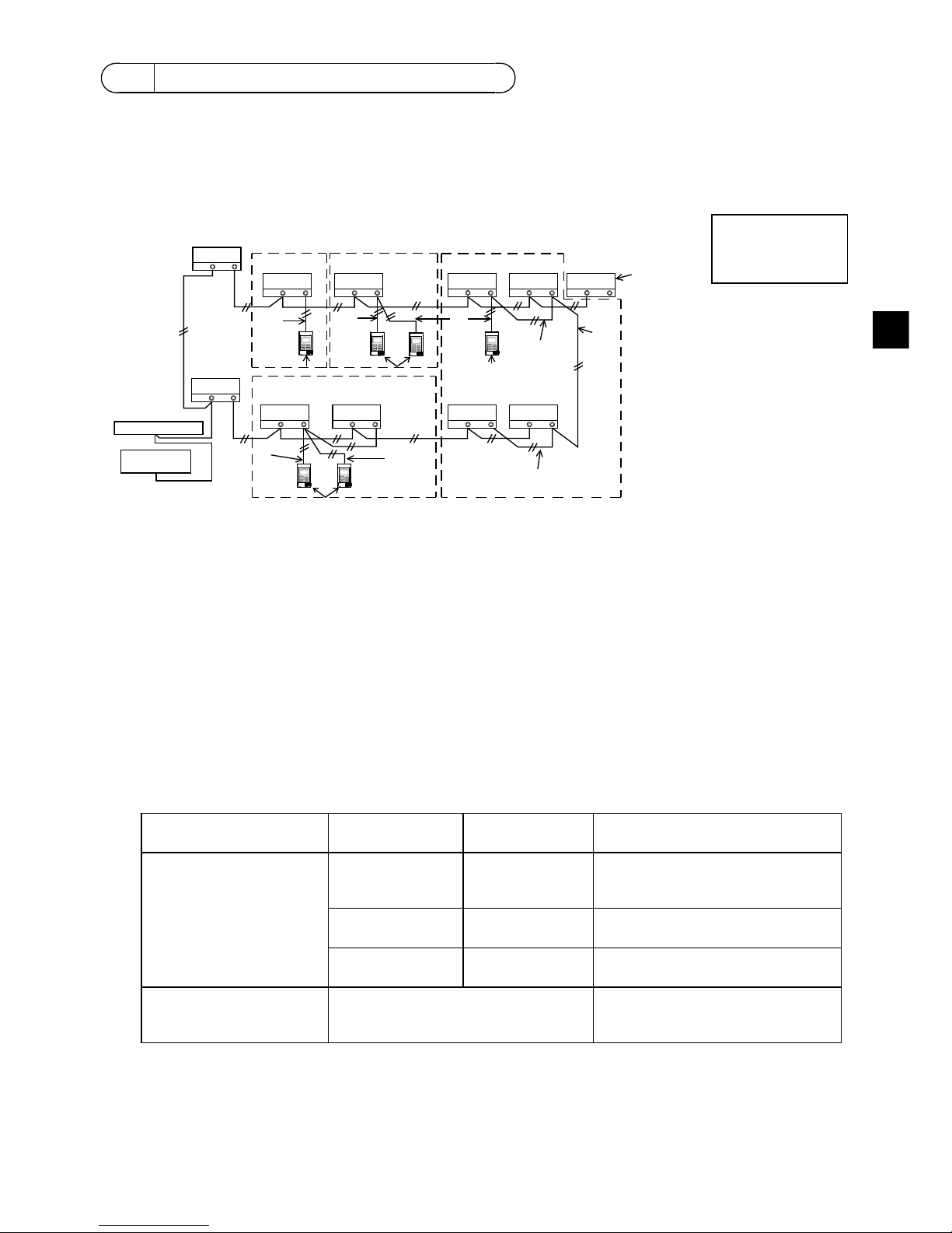
The wiring is different when the remote controller is connected to a CITY MULTI control system (“-A”
type and later) and when it is connected to a Mr. SLIM air conditioner (A control type). The wiring also
differs with the system configuration. Check the system used.
1. Connecting to CITY MULTI control system
The numbers (1) to (4) in the figure correspond to items (1) to (4) in the following description.
(1) Wiring from the remote controller
• Connect to the MA remote controller terminal block (TB15) on the indoor unit.
• The terminal block has no polarity. Connect to the terminal block at the rear bottom of the remote
controller.
(2) Operating in a group (Groups 03, and 04 above)
• Interconnect the MA remote controller terminal block (TB15) of the indoor units you want to
operate as a group, and connect the MA remote controller to that point.
• When the remote controller is used in combination with the system controller as shown in the
figure above, group setting at the system controller (central controller in the figure above) is
necessary.
(3) Number of connectable remote controllers (groups 02 and 04)
• A main remote controller and one sub remote controller, a total of two, can be connected to a
group made up of indoor units.
NOTE: When using this Simple MA remote controller in combination with other MA remote
controllers, be sure to follow the compatibility rules below.
4 How To Wire Transmission Line
Connect to TB15
on the indoor unit.
a Outdoor unit
b Indoor unit
c LOSSNAY or
OA processing unit
d Main Remote Controller
e Sub Remote Controller
f Central controller
g Power supply unit for
transmission line
Indoor unit function Main remote
controller
Sub remote
controller
Compatibility
Models applicable for
AUTO (dual set point)
mode
This Simple MA
remote controller
This Simple MA
remote controller
Compatible, and AUTO (dual set
point) mode can be used depending
on the indoor units to be connected.
Other MA remote
controllers
This Simple MA
remote controller
Compatible, but AUTO (dual set
point) mode cannot be used.
This Simple MA
remote controller
Other MA remote
controllers
Incompatible
Models not applicable for
AUTO (dual set point)
mode
Combination with all of the above Compatible
TB5 TB15
TB5 TB15
bb
TB5 TB15
c
TB5 TB15
b
TB5 TB15
b
TB5 TB15
b
TB5 TB15
b
TB7 TB3
TB5 TB15
TB5 TB15
TB7 TB3
(1)
(1)
(3)
(3)
(1)
(3)
(3)
(2)
(2)
(2)
(4)
(1)
(1)
a
a
dded
ed
bb
g
f
Address = 51
Address = 01 Address = 02
Address = 55
Address = 08
Address = 07
Address = 03
Address = 04 Address = 09
Address = 06
Address = 05
Group 01 Group 02 Group 03
Group 04
– 6 –
GB
(4) To interlock to a LOSSNAY or OA processing unit, make the following settings using the remote
controller. (For a description of how to set an interlock, see section .)
Set the LOSSNAY or OA processing unit address and the address of all the indoor units you want
to interlock.
(5) Total length of remote controller wiring
• The simple MA controller can be wired up to 200 m (656 ft).
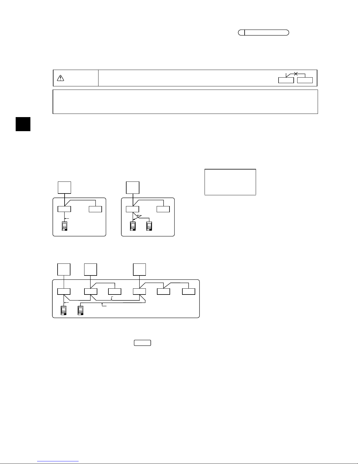
2. Connecting to Mr. SLIM air conditioner
The remote controller wiring depends on the system configuration. Check the system configuration.
Wire the remote controller as shown in the example below.
The numbers (1) to (3) in the figure correspond to items (1) to (3) in the following description.
[1] Connecting the remote controller for each refrigerant system (Standard 1:1, simultaneous twin,
simultaneous triple, simultaneous four)
[2] When grouping by different refrigerant systems
* Set the refrigerant address using the outdoor unit dip switches. (For more information, refer to the
outdoor unit installation manual.)
* All the indoor units enclosed in are controlled as one group.
(1) Wiring from remote controller
• Connect to indoor unit TB5 (remote controller terminal block). (The terminal block has no polarity.)
• For simultaneous multi type, when mixing various types of indoor units, always connect the
remote controller to the indoor unit with the most functions (wind velocity, vane, louver, etc.).
(2) When grouping with difference refrigerant systems
• Group using the remote controller wiring. Connect the remote controller to an arbitrary indoor unit
of each refrigerant system you want to group.
• When mixing different types of indoor units in the same group, always make the outdoor unit
connecting the indoor unit with the most functions (wind velocity, vane, louver, etc.) the Main unit
(refrigerant address = 00). Also, when the Main unit is the simultaneous multi type, always satisfy
the conditions of (1) above.
• The Simple MA Remote Controller can control up to 16 refrigerant systems as one group.
CAUTION
Remote controllers cannot be wired together. Only one wire
can be connected to the remote controller terminal block.
Connect to TB5
on the indoor unit.
a Outdoor unit
b Indoor unit
d Main Remote Controller
(Simple MA Controller)
e Sub Remote Controller
(Simple MA Controller)
7
Ventilation Setting
ed
NOTE: When interlocking the MA remote controller with a LOSSNAY or OA processing unit,
always set the address of all the indoor units in the group and the address of the
LOSSNAY or OA processing unit.
(1)
TB5
TB4
TB1
TB4
(3)
(3)(3)
(1)
TB4
TB4
TB5
TB1
a
bb
d
a
bb
de
Refrigerant
address = 00
Refrigerant
address = 00
Simultaneous twin Simultaneous twin
TB4
TB4
TB4
TB4
TB4TB4
TB1 TB1 TB1
TB5
TB5
TB5
(2)
(1)
(3)
(3)
(1)
(2)
aa a
bbbbbb
de
Standard 1:1 Simultaneous twin
Simultaneous triple
Refrigerant
address = 01
(Sub)
Refrigerant
address = 00
(Main)
Refrigerant
address = 02
(Sub)
– 7 –
GB
(3) Up to two remote controllers can be connected to one group
• When two remote controllers are connected to one group, always set the Main remote controller
and Sub remote controller.
• When only one remote controller is connected to one group, set it as the Main controller. When
two remote controllers are connected to one group, set the Main remote controller and Sub
remote controller. (For a description of how to set the Main/Sub switch, see step 5 in section
.)
NOTE: When using this Simple MA remote controller in combination with other MA remote
controllers, be sure to follow the compatibility rules below.
(4) Total length of remote controller wiring
• The Simple MA Remote Controller can be wired up to 500 m (1640 ft).
This remote controller is for the wall installation. It can be installed either in the switch box or directly
on the wall. When performing direct wall installation, wires can be thread through either back or top of
the remote controller.
(1) Selecting an installation site
Install the remote controller (switch box) on the site where the following conditions are met.
(a) A flat surface
(b) A place where the remote controller can measure the accurate indoor temperature
Sensors to monitor indoor temperature are on the indoor unit and on the remote controller. When
the room temperature is monitored with the sensor on the remote controller, the built-in sensor on
the Main remote controller monitors the room temperature. When using the sensor on the remote
controller, follow the instructions below.
Indoor unit function Main remote
controller
Sub remote
controller
Compatibility
Models applicable for
AUTO (dual set point)
mode
This Simple MA
remote controller
This Simple MA
remote controller
Compatible, and AUTO (dual set
point) mode can be used depending
on the indoor units to be connected.
Other MA remote
controllers
This Simple MA
remote controller
Compatible, but AUTO (dual set
point) mode cannot be used.
This Simple MA
remote controller
Other MA remote
controllers
Incompatible
Models not applicable for
AUTO (dual set point)
mode
Combination with all of the above Compatible
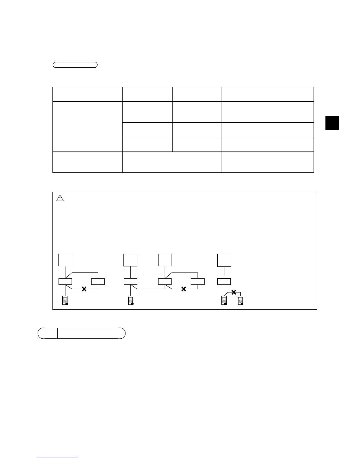
CAUTION - The wiring cannot be connected to TB5 of the indoor unit of the same
refrigerant system. If so connected, the system will not operate normally.
- Remote controllers cannot be wired together. Only one wire can be connected
to the remote controller terminal block.
- When connecting to TB5, connect up to two wires of the same size to one
terminal block.
a Outdoor unit
b Indoor unit
d Main Remote Controller
e Sub Remote Controller
5How To Install
5
How To Install
d
d
TB4
TB4
TB4
TB4
TB4
TB4
TB1
TB1 TB1
TB1
TB5
TB5
TB5
TB5 TB5 TB5
a
bbb bbb
de
aa a
Refrigerant
address = 00
Refrigerant
address = 00
Refrigerant
address = 01
Refrigerant
address = 00
Simultaneous twin Standard 1:1 Simultaneous twin Standard 1:1
– 8 –
GB
• To monitor the accurate indoor temperature, install the remote controller away from direct
sunlight, heat sources, and the supply air outlet of the air conditioner.
• Install the remote controller in a location that allows the sensor to measure the representative
room temperature.
• Install the remote controller where no wires are routed around the temperature sensor on the
controller. (If wires are routed, the sensor cannot measure accurate indoor temperature.)
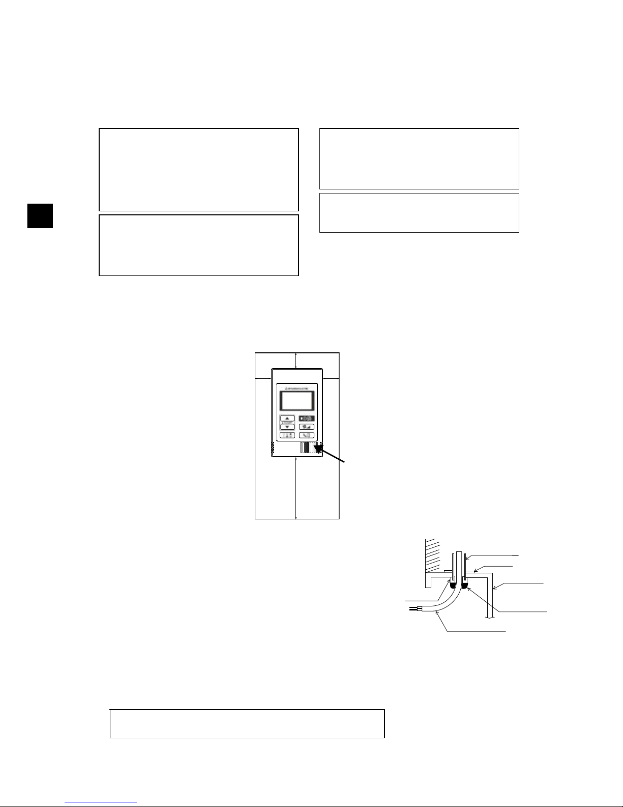
(2) Installation space
Leave a space around the remote controller as shown in the figure shown below, regardless of
whether the controller is installed in the switch box or directly on the wall. Removing the remote
controller will not be easy with insufficient space.
Also, leave an operating space in front of the remote controller.
(3) Installation work
Controller can be installed either in the switch box or directly on the
wall. Perform the installation properly according to the installation
method.
1 Drill a hole in the wall.
■ Installation using a switch box
• Drill a hole in the wall, and install the switch box on the wall.
• Connect the switch box to the conduit tube.
■ Direct wall installation
• Drill a hole in the wall, and thread the cable through it.
2 Seal the cable access hole with putty
■ Installation using a switch box
• Seal the remote controller cable access hole at the
connection of switch box and conduit tube with putty.
Do not install the controller in a place where
the difference between the remote controller
surface temperature and the actual room
temperature will be great.
If the temperature difference is too high,
room temperature may not be adequately
controlled.
To reduce the risk of malfunctions, do not
install the controller in a place where water
or oil may come into contact with the
controller, or in a condensing or corrosive
environments.
To avoid deformation and malfunction, do
not install the remote controller in direct
sunlight or where the ambient temperature
may exceed 40ºC (104ºF) or drop below 0ºC
(32ºF).
Do not install the remote controller directly
onto electrically conductive objects such as
metal plate that has not been painted.
Important
30
(1-3/16)
30
(1-3/16)
30 (1-3/16)
120 (4-3/4)
Temperature sensor
unit: mm (in)
External dimensions of remote controller
Minimum required space
around the remote
controller
Wall
Conduit tube
Locknut
Switch box
Seal the gap
with putty.
Remote
controller cable
Bushing
To reduce the risk of electric shock, malfunctions, or fire, seal
the gap between the cables and cable access holes with putty.
 Loading...