

Mitsubishi Electric City Multi PAC-LV11M-J Installation Manual
AIR CONDITIONING SYSTEMS
CONNECTION KIT
PAC-LV11M-J
GB
INSTALLATION MANUAL
For safe and correct use, please read this installation manual thorou ghly before installing the indoor unit.
2
GB
Contents
1. Safety precautions ........................................................................ 2
1.1. Before installation and electric work .............................. 2
1.2. Precautions for devices that use R410A refrigerant ...... 2
1.3. Before getting installed .................................................. 3
1.4. Before getting installed (moved) - electrical work..........3
1.5. Before starting the test run............................................. 3
2. Overview of units........................................................................... 4
2.1. System outline ............................................................... 4
2.2. Unit construction............................................................ 4
2.3. Installation...................................................................... 5
2.4. Dip switch setting..........................................................18
3. Specifications...............................................................................18
4. Outlines and dimensions..............................................................1 9
5. Wiring diagram.............................................................................20
6. Refrigerant system diagram.........................................................21
7. Troubleshooting...........................................................................22
7.1. Test run.........................................................................22
7.2. Check methods.............................................................23
7.3. Dip switch setting (Factory setting)...............................26
1. Safety precautions
1.1. Before installation and electric work
Symbols used in the text
Warning:
Describes precautions that should be observed to prevent danger of injury
or death to the user.
Caution:
Describes precautions that should be observed to prevent damage to the
unit.
Symbols used in the illustrations
Warning:
• Ask the dealer or an authorized technician to install the connection kit.
- Improper installation by the user may result in water leakage, electric shock,
or fire.
• Install the unit at a place that can withstand its weight.
- Inadequate strength may cause the unit to fall down, resulting in injuries.
• Use the specified cables for wiring. Make the connections securely so
that the outside force of the cable is not applied to the terminals.
- Inadequate connection and fastening may generate heat and cause a fire.
• Prepare for typhoons and other strong winds and earthquakes and
install the unit at the specifie d pl ac e.
- Improper installation may cause the unit to topple and result in injury.
• Always use an air cleaner, humidifier, electric heater, and other accessories specified by Mitsubishi Electric.
- Ask an authorized technician to install the accessories. Improper installation
by the user may result in water leakage, electric shock, or fire.
• Never repair the unit. If the unit must be repaired, consult the dealer.
- If the unit is repaired improperly, water leakage, electric shock, or fire may
result.
• When handling this product, always wear protective equipment.
EG: Gloves, full arm protection namely boiler suit, and safety glasses.
- Improper handling may result in injury.
• If refrigerant gas leaks during installation work, ventilate the room.
- If the refrigerant gas comes into contact with a flame, poisonous gases will
be released.
• Install the unit according to this Installation Manual.
- If the unit is installed improperly, water leakage, electric shock, or fire may
result.
• Have all electric work done by a licensed electrician according to “Electric Facility Engineering Standard” and “Interior Wire Regulations” and
the instructions given in this manual and always use a special circuit.
- If the power source capacity is inadequate or electri c work is performed
improperly, electric shock and fire may result.
• Keep the electric parts away from water (washing water etc.).
- It might result in electric shock, catching fire or smoke.
• When installing and moving the unit to another site, do not charge the it
with a refrigerant different from the refrigerant specified on the unit.
- If a different refrigerant or air is mixed with the original refrigerant, the refrig-
erant cycle may malfunction and the unit may be damaged.
• If the unit is installed in a small room, measures must be taken to prevent the refrigerant concentration from exceeding the safety limit even
if the refrigerant should leak.
- Consult the dealer regarding the appropriate measures to prevent the safety
limit from being exceeded. Should the refrigerant leak and cause the safety
limit to be exceeded, hazards due to lack of oxygen in the room could result.
• When moving and reinstalling the unit, consult the dealer or an authorized technician.
- If the air conditioner is installed improperly, water leakage, electric shock, or
fire may result.
• After completing installation work, make sure that ref rigerant gas is not
leaking.
- If the refrigerant gas leaks and is exposed to a fan heater, stove, oven, or
other heat source, it may generate noxious gases.
• Do not reconstruct or change the settings of the protection devices.
- If the pressure switch, thermal switch, or other protection device is shorted
and operated forcibly, or parts other than those specified by Mitsubishi Electric are used, fire or explosion may result.
• To dispose of this product, consult your dealer.
• Do not use a leak detection additive.
1.2. Precautions for devices that use
R410A refrigerant
Caution:
• Do not use the existing refrigerant piping.
- The old refrigerant and refrigerator oil in the existing piping contains a large amount
of chlorine which may cause the refrigerator oil of the new unit to deteriorate.
• Use refrigerant piping made of C1220 (Cu-DHP) phosphorus deoxidized
copper as specified in the JIS H3300 “Copper and copper alloy seamless pipes and tubes”. In addition, be sure that the inner and outer surfaces of the pipes are clean and free of hazardous sulphur, oxides, dust/
dirt, shaving particles, oils, moisture, or any other contaminant.
- Contaminants on the inside of the refrigerant piping may cause the refriger-
ant residual oil to deteriorate.
• Store the piping to be used during installation indoors and keep both
ends of the piping sealed until just before brazing. (Store elbows and
other joints in a plastic bag.)
- If dust, dirt, or water enters the refrigerant cycle, deterioration of the oil and
compressor trouble may result.
• Use liquid refrigerant to fill the system.
- If gas refrigerant is used to seal the system, the composition of the refriger-
ant in the cylinder will change and performance may drop.
• Do not use a refrigerant other than R410A.
- If another refrigerant (R22, etc.) is used, the chlorine in the refrigerant may
cause the refrigerator oil to deteriorate.
• Use a vacuum pump with a reverse flow check valve.
- The vacuum pump oil may flow back into the refrigerant cycle and cause the
refrigerator oil to deteriorate.
• Do not use the following tools that are used with conventional refrigerants.
(Gauge manifold, charge hose, gas leak detector, reverse flow check
valve, refrigerant charge base, vacuum gauge, refrigerant recovery
equipment)
- If the conventional refrigerant and refrigerator oil are mixed in the R410A, the
refrigerant may deteriorated.
- If water is mixed in the R410A, the refrigerator oil may deteriorate.
- Since R410A does not contain any chlorine, gas leak detectors for conven-
tional refrigerants will not react to it.
• Do not use a charging cylinder.
- Using a charging cylinder may cause the refrigerant to deteriorate.
• Be especially careful when managing the tools.
Before installing the unit, make sure you read all the “Safety precau-
tions”.
The “Safety precautions” provide very important points regarding
safety. Make sure you follow them.
: Indicates an action that must be avoided.
: Indicates that important instructions must be followed.
: Indicates a part which must be grounded.
: Indicates that caution should be taken with rotating parts. (This symbol is
displayed on the main unit label.) <Color: yellow>
: Beware of electric shock (This symbol is displayed on the main unit label.)
<Color: yellow>
Warning:
Carefully read the labels affixed to the main unit.
3
GB
- If dust, dirt, or water gets in the refrigerant cycle, the refrigerant may deteriorate.
1.3. Before getting installed
Caution:
• Do not install the unit where combustible gas may leak.
- If the gas leaks and accumulates around the unit, an explosion may result.
• Do not use the connection kit where food, pets, plants, precision instruments, or artwork are kept.
- The quality of the food, etc. may deteriorate.
• Do not use the unit in special environments.
- Oil, steam, sulfuric smoke, etc. can significantly reduce the performance of
the unit or damage its parts.
• When installing the unit in a hospital, communication station, or similar
place, provide sufficient protection against noise.
- T he inverter equipment, private power generator, high-frequency medical
equipment, or radio communication equipment may cause the air conditioner to operate erroneously, or fail to operate. On the other hand, the unit
may affect such equipment by creating noise that disturbs medical treatment
or image broadcasting.
• Do not install the unit on a structure that may cause leakage.
- When the room humidity exceeds 80% or when the drain pipe is clogged,
condensation may drip from the indoor unit. Perform collective drainage
work together with the outdoor unit, as required.
• The unit should be installed the ceiling over than 2.5 m from floor.
1.4. Before getting installed (moved) -
electrical work
Caution:
• Ground the unit.
- Do not connect the ground wire to gas or water pipes, lightning rods, or tele-
phone ground lines. Improper grounding may result in electric shock.
• Install the power cable so that tension is not applied to the cable.
- Tension may cause the cable to break and generate heat and cause a fire.
• Install a leak circuit breaker, as required.
- If a leak circuit breaker is not installed, electric shock may result.
• Use power line cables of sufficient current carrying capacity and rating.
- Cables that are too small may leak, generate heat, and cause a fire.
• Use only a circuit breaker and fuse of the specified capacity.
- A fuse or circuit breaker of a larger capacity or a steel or copper wire may
result in a general unit failure or fire.
• Do not wash the unit.
- Washing them may cause an electric shock.
• Be careful that the installation base is not damaged by long use.
- If the damage is left uncorrected, the unit may fall and cause personal injury
or property damage.
• Install the drain piping a ccording to this In stallation Manual to ensure
proper drainage. Wrap thermal insulation around the pipes to prevent
condensation.
- Improper drain piping may cause water leakage and damage to furniture and
other possessions.
• Be very careful about product transportation.
- Some products use PP bands for packaging. Do not use any PP bands for a
means of transportation. It is dangerous.
• Safely dispose of the packing materials.
- Packing materials, such as nails and other metal or wooden parts, may
cause stabs or other injuries.
- Tear apart and throw away plastic packaging bags so that children will not
play with them. If children play with a plastic bag which was not torn apart,
they face the risk of suffocation.
1.5. Before starting the test run
Caution:
• Turn on the power at least 12 hours before starting operation.
- Starting operation immediately after turning on the main power switch can
result in severe damage to internal parts. Keep the power switch turned on
during the operational season.
• Do not touch the switches with wet fingers.
- Touching a switch with wet fingers can cause electric shock.
• Do not touch the refrigerant pipes during and immediately after operation.
- During and immediately after operation, the refrigerant pipes are may be hot
and may be cold, depending on the condition of the refrigerant flowing
through the refrigerant piping, compressor, and other refrigerant cycle parts.
Your hands may suffer burns or frostbite if you touch the refrigerant pipes.
• Do not operate the unit with the panels and guards removed.
- Rotating, hot, or high-voltage parts can cause injuries.
• Do not turn off the power immediately after stopping operation.
- Always wait at least five minutes before turning off the power. Otherwise,
water leakage and trouble may occur.
• If the supply cord is damaged, it must be replaced by the manufacturer,
its service agent or similarly qualified persons in order to avoid a hazard.
• This appliance is not intended for use by persons (including children)
with reduced physical, sensory or mental cap abiliti es, or lack of exper ience and knowledge, unless they have been given supervision or
instruction concerning use of the appliance by a person responsible for
their safety.
• Children should be supervised to ensure that they do not play with the
appliance.
4
GB
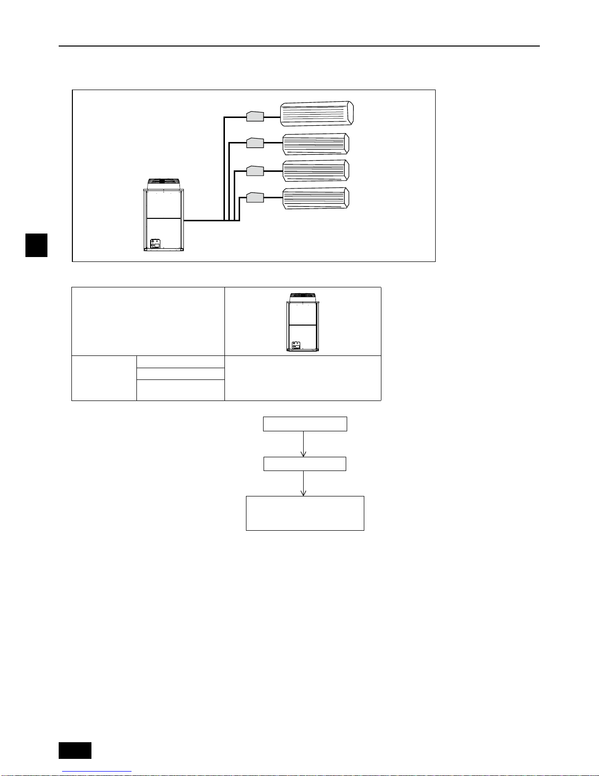
2. Overview of units
2.1. System outline
2.1.1. System example
2.2. Unit construction
Outdoor unit
Indoor unit that
can be
connected
Capacity
Refer to manuals of the outdoor unit.
Number of units
Total system wide
capacity
Outdoor unit
Connection kit
Connection kit
Connection kit
Connection kit
Branching Pipe
Wall mounted
Connection kit
+
* For connectable indoor unit
models, consult your dealer.
5
GB
2.3. Installation
2.3.1. Installing the connection kit
Parts to procure locally
• Suspension bolts or anchor bolts : W3/8 (M10)
• Nut : W3/8 (M10)
• Washer : W3/8 (M10)
Installing the unit in a ceiling
(1) Install the suspension bolts.
(2) Install the connection kit.
Installing the unit on a wall
(1) Install the anchor nuts.
(2) Install the connection kit.
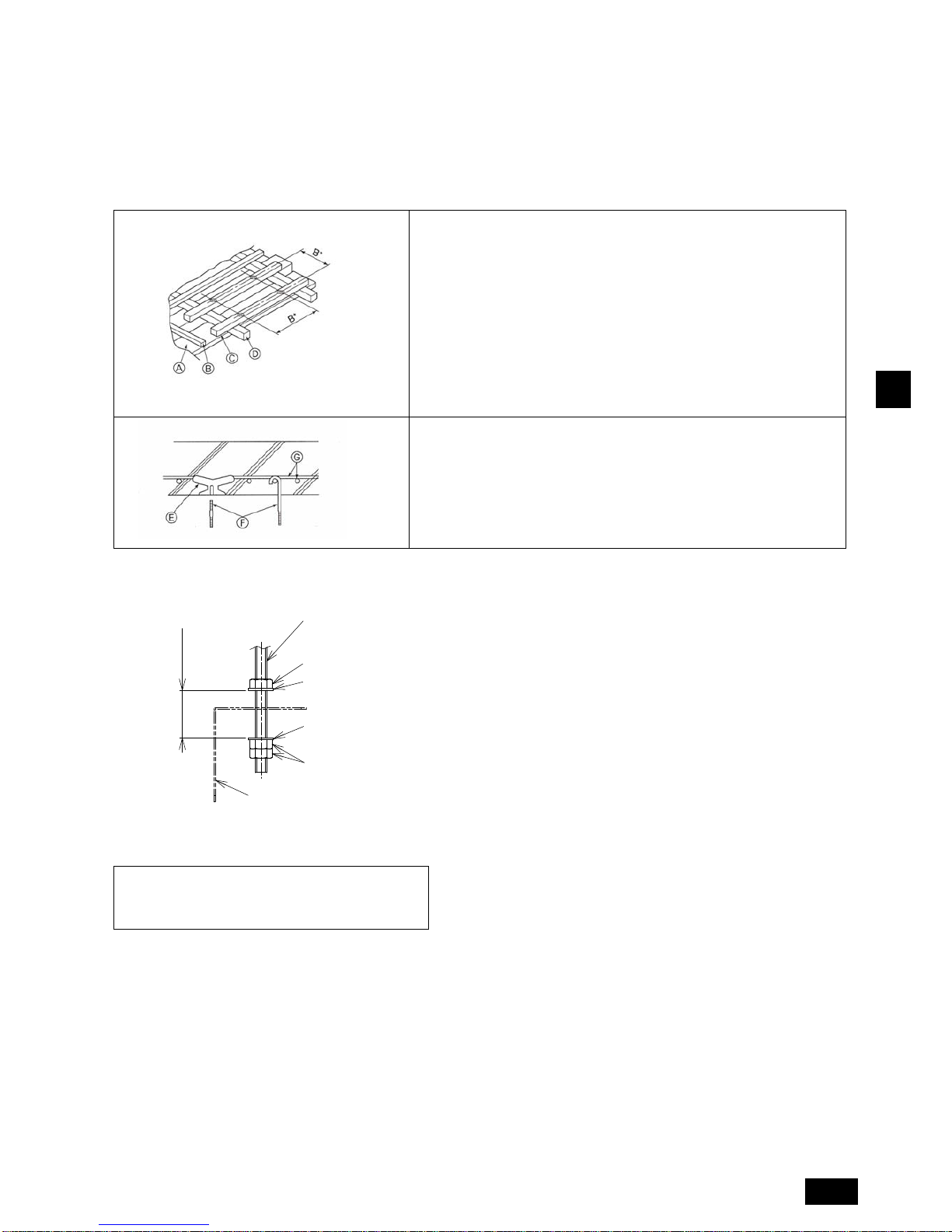
Wooden structures
• Use tie beams (single storied houses) or second floor beams (two
story houses) as reinforcing members.
• Wooden beams for suspending air conditioners must be sturdy and
their sides must be at least 6 cm long if the beams are separated by
not more than 90 cm. The size of the suspension bolts should be
M10 (W3/8). (The bolts are not supplied with the unit.)
A Ceiling
B Rafter
C Beam
D Roof beam
B* Suspension bolt pitch
Ferro-concrete structures
Secure the suspension bolts using the method shown, or use
steel or wooden hangers, etc. to install the suspension bolts.
E Use inserts rated at 100-150 kg each (procure locally)
F Suspension bolts M10 (W3/8) (procure locally)
G Steel reinforcing rod
Do not install the refrigerant pipes on top of the
unit when installing the unit on a wall, otherwise
condensation can enter the electrical devices,
which can cause an electric shock or a fire.
Unit
Washer (procure locally)
Washer (procure locally)
Nuts (procure locally)
Nut (procure locally)
Suspension bolt M10
ޓ(procure locally)
(When unit is hung
and nuts tightened)
MIN.30
(Unit: mm)
6
GB
Connect the Connection Kit to the liquid pipe and install it inside the ceiling or on a wall (Do not install in an outdoor location. It may
cause a breakdown). Make sure to install the access door on the ceiling.
Installation location
• The installation patterns below are available. Select the installation pattern according to the preferred installation method. The
distance between indoor unit and Connection Kit is within 15 m. (Pipe:15 m, Cable:2.5 m)
• Install the connection kit at a height of 2.5 m or above from the floor, where it is not easily accessible for the users.
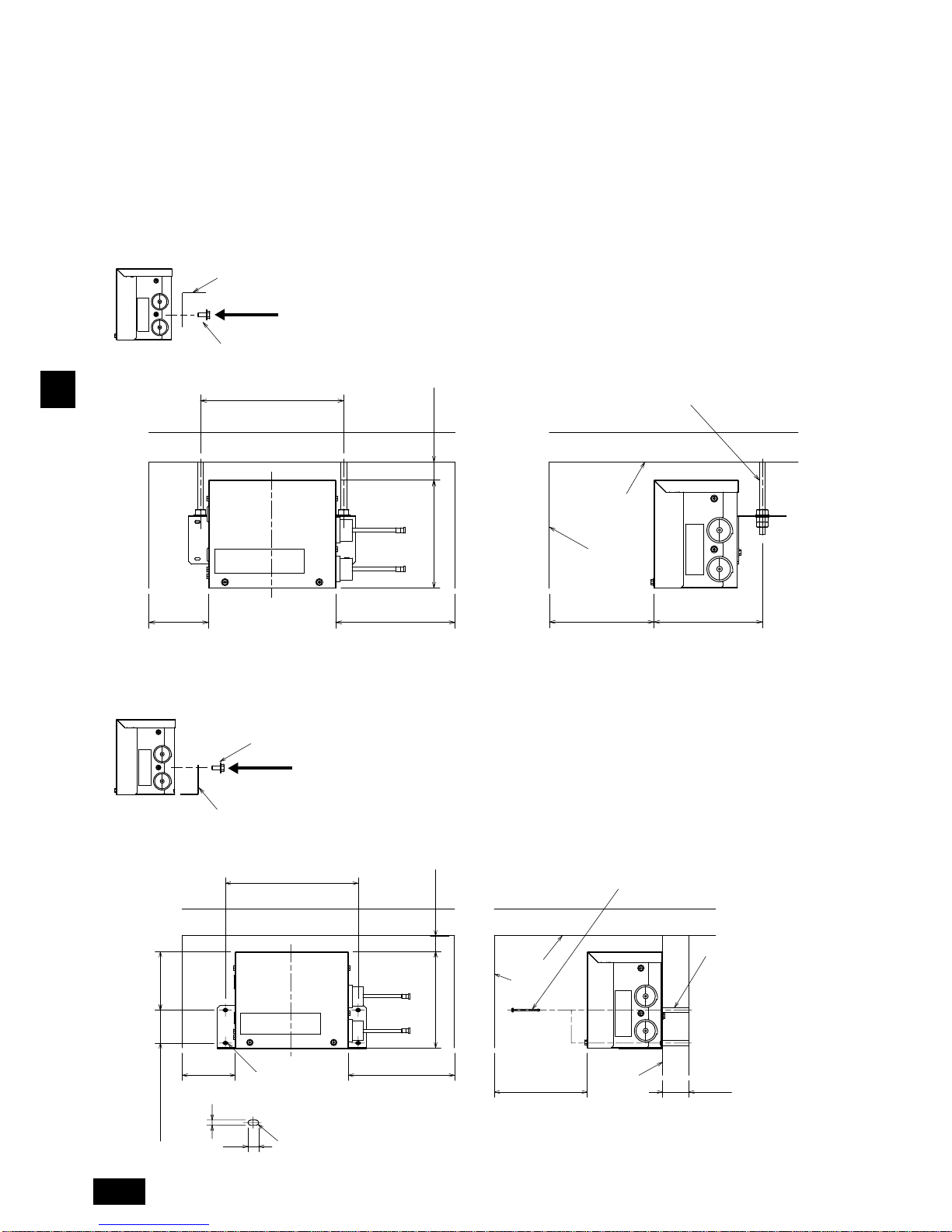
Installation pattern A (Using suspension bolt ; recommended pa tte rn)
Set the Connection Kit mounting plate as shown below.
The mounting plate can also be fixed to suspension bolts before it is fixed to the Connection Kit.
Installation pattern B (Installing the unit on a wall.)
Set the Connection Kit mounting plate as shown below.
Mounting plate
Install the two screws (5 × 10)
Wall
Ceiling
Suspension bolt M10
182
SERVICE SPACE
MIN.500
MIN.100 MIN.200
181
MIN.30
Suspension bolt pitch
240
Mounting plate
Install the two screws (5 × 10)
Wall
Wall
Ceiling
4-Oval holes
Anchor nuts
(procure locally)
Oval hole dimension
Install the four screws (4×50 procure
locally) in oval holes.
(R)
10
5
MIN.50
110
ANCHOR NUT PITCH
62
ANCHOR NUT PITCH
250
SERVICE SPACE
MIN.500
MIN.100 MIN.200
181 MIN.30
(Unit: mm)
(Unit: mm)
7
GB
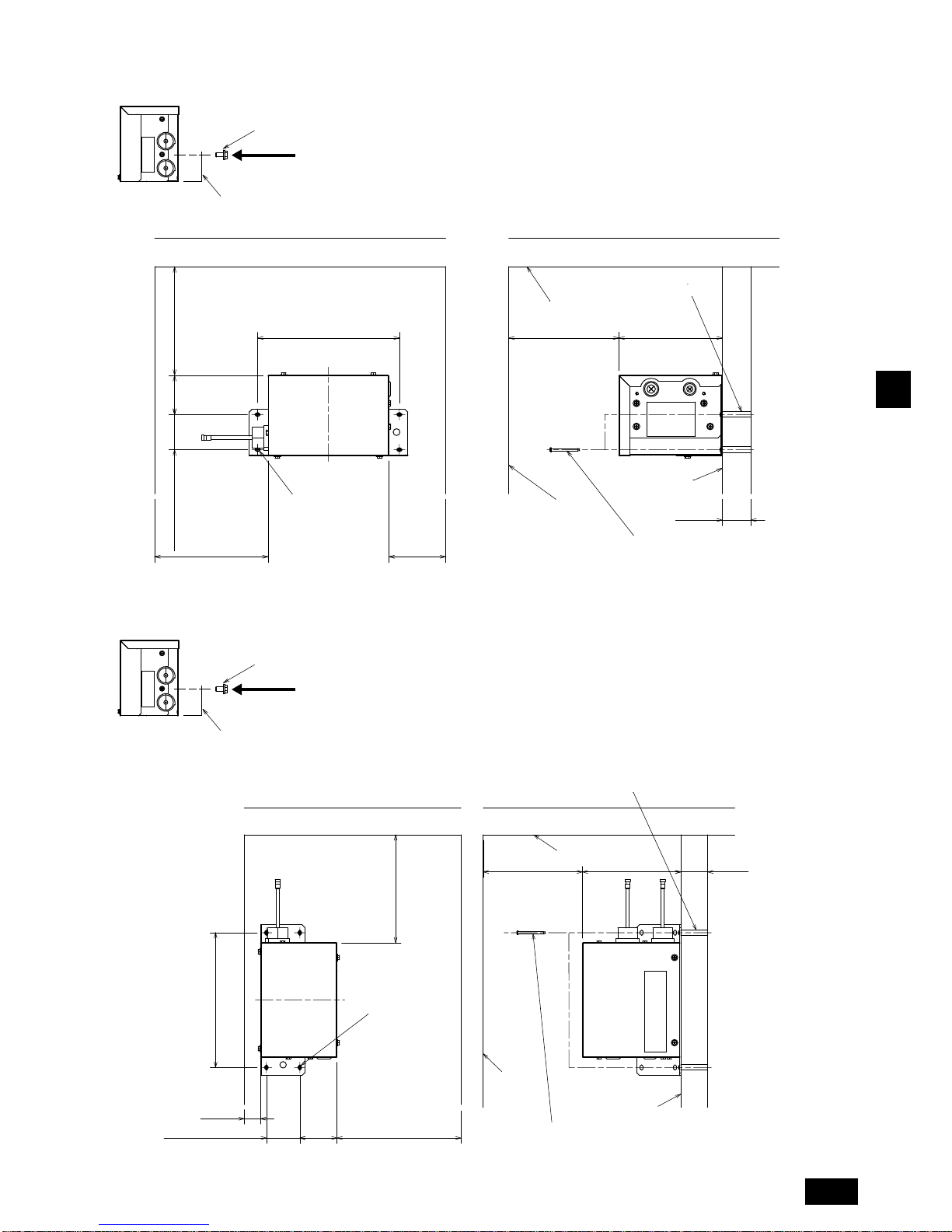
Installation pattern C (Installing the unit on a wall.)
Set the Connection Kit mounting plate as shown below.
Installation pattern D (Installing the unit on a wall.)
Set the Connection Kit mounting plate as shown below.
Mounting plate
Install the two screws (5 × 10)
Install the four screws (4×50 procure
locally) in oval holes.
Anchor nuts
(procure locally)
Wall
Wall
Ceiling
4-Oval holes
183
SERVICE SPACE
500
SERVICE SPACE
500
69
MIN.100MIN.200
ANCHOR NUT PITCH
62
ANCHOR NUT PITCH
250
MIN.50
Mounting plate
Install the two screws (5 × 10)
Install the four screws (4×50 procure
locally) in oval holes.
Wall
Wall
Ceiling
4-Oval holes
Anchor nuts
(procure locally)
ANCHOR NUT PITCH
250
MIN.50
183MIN.30
69
MIN.30
MIN.200
SERVICE SPACE
500
ANCHOR NUT PITCH
62
(Unit: mm)
(Unit: mm)
8
GB
2.3.2. Installing the refrigerant piping
Check the Connection Kit accessories and parts
1Pipe cover × 2
2Thermistor holder - ø9.52 × 1
3Thermistor holder - ø12.7 × 1
Connect Connection Kit to the liquid pipe.
When brazing the refrigerant pipes, be sure to braze, after covering a wet cloth to the insulation pipes of the units in order to prevent
it from burning and shrinking by heat.
Press the pipe cover 1 on the liquid piping against the Connection Kit and wrap it to hold it in place.
Fasten the supplied bands 20 mm from each of the pipe covers 1.
Wrap the pipe cover 1 with tape.
Connection kit
Refrigerant pipe (procure locally)
Brazing
To indoor unit
To outdoor unit
(120)
2020
Connection kit
Band (procure locally)
Refrigerant pipe
(procure locally)
1Pipe cove
r
Tape (procure locally)
9
GB
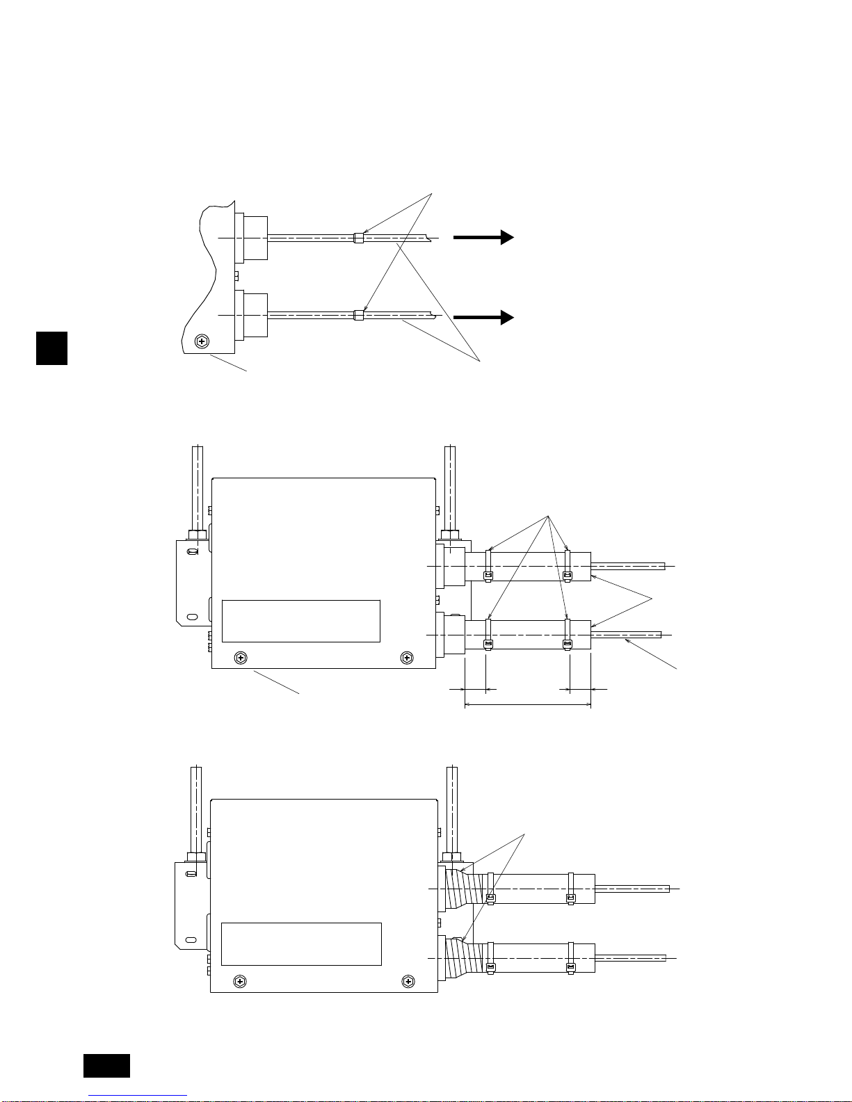
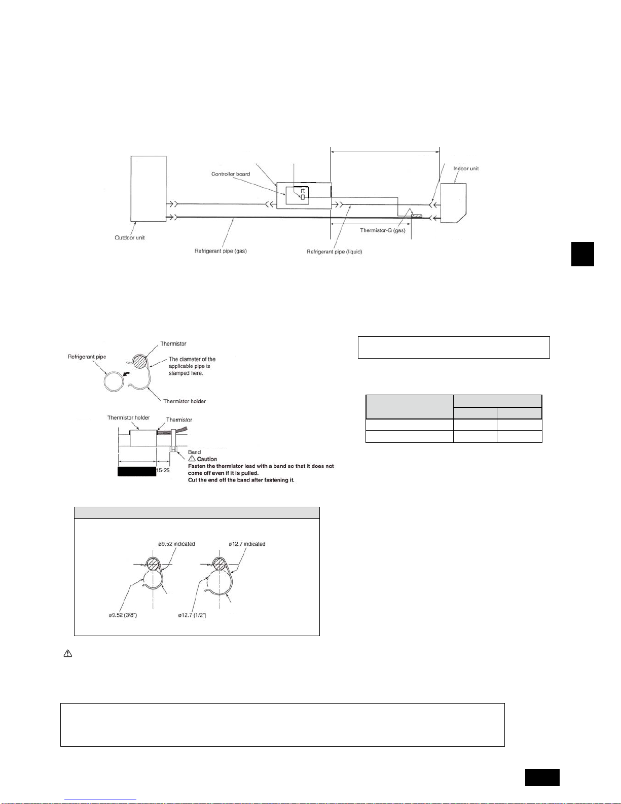
2.3.3. Installing the thermistors
Be sure to install the thermistors (gas) supplied with the unit as shown in the illustration.
• If the thermistors are not installed, the unit will not operate. If the thermistors are installed incorrectly, the unit will not operate
properly.
Take precaution so that condensation does contact the thermistor leads or enters the electrical devices.
Before installing thermal insulation to the frame connecting points of the indoor unit, be sure to install the thermistors
according to the procedures given on this page.
* Refer to section 8.4 "Wiring (mm)" for the location of CN44.
Thermistor installation order
(1) Securely fasten the thermistor (gas) supplied with the unit using the thermistor holders (2, 3) at the fastening points of indoor
unit refrigerant pipes.
• Set thermistor-G (gas) in thermistor holders 2 or 3, and then fasten the refrigerant pipes.
Caution:
• To prevent condensation from dripping on the thermistor fasteners, wrap them with sufficient thermal insulation.
• Install the thermistor so that the piping is on top (as shown in above illustration).
• Take out the thermistor lead from above the piping.
• Install the thermistor indoors.
Select thremistor holders that match the size
of the refrigerant piping.
Gas
• Route the following lead, line, and cable pairs so that they do not come into contact with each other.
- Thermistor lead and indoor unit-connection kit transmission line
- Thermistor lead and power supply cable
- Transmission line and power supply cable
Connection kit
Gas: CN44
1500
Brazed point
MAX. 15000
MAX. 2000
MAX. 1500 mm
(procure locally)
Indoor unit capacity pipe size (mm)
15-40
50
Liquid
ø6.35
ø6.35
Gas
ø9.52
ø12.7
2
3
 Loading...