

Mitsubishi Electric CITY MULTI CMH-WM-V-A, CITY MULTI CMH-WM250V-A, CITY MULTI CMH-WM350V-A, CITY MULTI CMH-WM500V-A Data Book

AIR CONDITIONING SYSTEMS
MODEL
CMH-WM-V-A

CONTENTS
CMH-WM-V-A
I.Hydro unit
1. SPECIFICATIONS .................................................................................................................................... 2
2. EXTERNAL DIMENSIONS ....................................................................................................................... 5
3. CENTER OF GRAVITY ............................................................................................................................ 7
4. ELECTRICAL WIRING DIAGRAMS ......................................................................................................... 8
5. SOUND LEVELS ...................................................................................................................................... 9
5-1. Sound levels .................................................................................................................................... 9
5-2. NC curves ........................................................................................................................................ 9
6. ELECTRICAL CHARACTERISTICS......................................................................................................... 10
7. INSTALLATION ........................................................................................................................................ 11
7-1. Lifting method .................................................................................................................................. 11
8. OPTIONAL PARTS................................................................................................................................... 12
8-1. Drain pan ......................................................................................................................................... 12
Hydro unit
MEES18K070
1

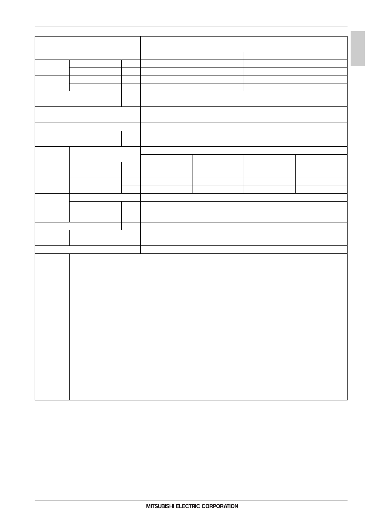
1. SPECIFICATIONS
I.Hydro unit1. SPECIFICATIONS
Model name CMH-WM250V-A
Power source 1-phase 220-230-240 V
50 Hz 60 Hz
Power input Cooling kW 0.74/0.74/0.74 0.74/0.74/0.74
(220/230/240) Heating kW 0.74/0.74/0.74 0.74/0.74/0.74
Current input Cooling A 3.84/3.67/3.52 3.84/3.67/3.52
(220/230/240) Heating A 3.84/3.67/3.52 3.84/3.67/3.52
Hydro unit
Sound pressure level (measured in anecho ice room) dB <A> 60
Applicable temperature range of installation site °C (D.B.) -5~52
External finish Pre-coated galvanized steel sheets
(Lower part drain pan: Pre-coated galvanized sheets + powder coating)
Connectable outdoor/heat source unit capacity (E)M200~250
External dimension H x W x D mm 660 x 920 x 740
in.
Refrigerant piping
diameter
Water piping
diameter
Net weight kg (lbs) 112 (247) [119 (263) with water]
Standard
attachment
Optional parts Drain pan (PAC-SH01DP-E)
Note 1.Works not included:
To outdoor/heat source unit Connectable outdoor/heat source unit capacity
M200 M250 EM200 EM250
Liquid pipe mm (in.) 9.52 (3/8) 9.52 (3/8) 9.52 (3/8) 9.52 (3/8)
O.D.
Gas pipe mm (in.) 22.2 (7/8) 22.2 (7/8) 22.2 (7/8) 22.2 (7/8)
O.D.
To Indoor unit
Inlet Pipe
Outlet Pipe
Document
Accessories Y-type strainer, Auto air vent valve, Joint, Elbow, Pipe
Installation/foundation work, electrical connection work, duct work, insulation work, power source switch, and other items are not specified in this specifications.
2.The equipment is for R32 refrigerant.
3.Install this product in a location where noise (refrigerant noise) emitted by the unit will not disturb the neighbors.
(For use in quiet environments with low background noise, position the Hydro unit at least 5 m away from any indoor units.)
4.Please install the Hydro unit in a place where noise will not be an issue.
5.Please attach an expansion vessel (field supply).
6.Use copper, plastic, steel, or stainless steel pipes for the water circuit. Furthermore, when using copper pipe-work use a non-oxidative brazing method.
Oxidation of the pipe-work will reduce the pump life.
7.When brazing the pipes, be sure to braze, after covering a wet cloth to the insulation pipes of the units in order to prevent it from burning and shrinking by heat.
8.Please install an air purge valve where air will gather in the water circuit.
9.Please install a pressure reducing valve and a strainer on the water supply to the Hydro unit.
10.Please refer to the databook or the installation manual for the specified water quality.
11.Please always make water circulate or pull out the circulation water completely when not using it. *Please do not use it as a drinking water.
12.Please do not use ground water and well water.
13.When installing the Hydro unit in an environment which may drop below 0 °C, please add antifreeze to the circulating water.
(Refer to the data-book and the installation manual).
14.R32 is flammable, and certain restrictions apply to the installation of units.
When installing new units, moving the existing units, or changing the layout of the room,
ensure that installation restrictions are observed.
For detail, refer to the section in the Databook on installation restrictions.
15.Drain or condensation water will be discharged from hydro units during test run. If this will be a problem, install a separately sold drain pan.
16.Do not install the unit where it could be salt-damaged.
mm (in.)
I.D.
mm (in.)
I.D.
Brazed Brazed Brazed Brazed
Brazed Brazed Brazed Brazed
25-63/64 x 36-7/32 x 29-9/64
40 (1-1/2) housing joint
40 (1-1/2) housing joint
–
Hydro unit
MEES18K070
2
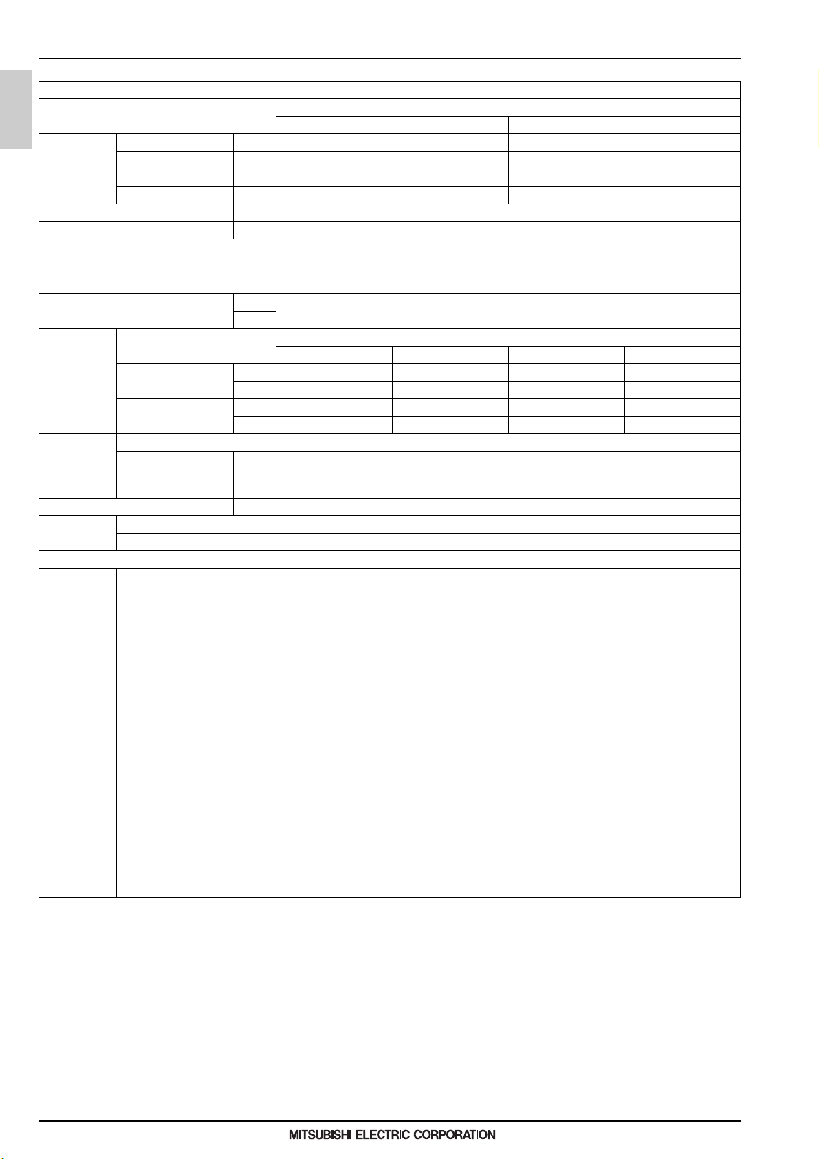
1. SPECIFICATIONS
Model name CMH-WM350V-A
Power source 1-phase 220-230-240 V
50 Hz 60 Hz
Power input Cooling kW 0.90/0.90/0.90 0.90/0.90/0.90
(220/230/240) Heating kW 0.90/0.90/0.90 0.90/0.90/0.90
Current input Coo ling A 4.69/4.48/4.30 4.69/4.48/4.30
(220/230/240) Heating A 4.69/4.48/4.30 4.69/4.48/4.30
Sound pressure level (measured in anechoice room) dB <A> 60
Applicable temperature range of installation site °C (D.B.) -5~52
External finish Pr e-coated galvanized steel sheets
(Lower part drain pan: Pre-coated galvanized sheets + powder coating)
Connectable outdoor/heat source unit capacity (E)M300~350
External dimension H x W x D mm 660 x 920 x 740
in.
Refrigerant piping
diameter
Water piping
diameter
Net weight kg (lbs) 122 (26 9) [126 (278) with water]
Standard
attachment
Optional parts Drain pan (PAC-SH01DP-E)
Note 1.Works not included:
To outdoor/heat source unit Connectable outdoor/heat source unit capacity
M300 M350 EM300 EM350
Liquid pipe mm (in.) 9.52 (3/8) 12.7 (1/2) 9.52 (3/8) 12.7 (1/2)
O.D.
Gas pipe mm (in.) 22.2 (7/8) 28.58 (1-1/8) 28.58 (1-1/8) 28.58 (1-1/8)
O.D.
To Indoor unit
Inlet Pipe
Outlet Pipe
Document
Accessories Y-type strainer, Auto air vent valve, Joint, Elbow, Pipe
Installation/foundation work, electrical connection work, duct work, insulation work, power source switch, and other items are not specified in this specifications.
2.The equipment is for R32 refrigerant.
3.Install this product in a location where noise (refrigerant noise) emitted by the unit will not disturb the neighbors.
(For use in quiet environments with low background noise, position the Hydro unit at least 5 m away from any indoor units.)
4.Please install the Hydro unit in a place where noise will not be an issue.
5.Please attach an expansion vessel (field supply).
6.Use copper, plastic, steel, or stainless steel pipes for the water circuit. Furthermore, when using copper pipe-work use a non-oxidative brazing method.
Oxidation of the pipe-work will reduce the pump life.
7.When brazing the pipes, be sure to braze, after covering a wet cloth to the insulation pipes of the units in order to prevent it from burning and shrinking by heat.
8.Please install an air purge valve where air will gather in the water circuit.
9.Please install a pressure red ucing valve and a strainer on the water supply to the Hydro unit.
10.Please refer to the databook or the installation manual for the specified water quality.
11.Please always make water circulate or pull out the circulation water completely when not using it. *Please do not use it as a drinking water.
12.Please do not use ground water and well water.
13.When installing the Hydro unit in an environment which may drop below 0 °C, please add antifreeze to the circulating water.
(Refer to the data-book and the installation manual).
14.R32 is flammable, and certain restrictions apply to the installation of units.
When installing new units, moving the existing units, or changing the layout of the room,
ensure that installation restrictions are observed.
For detail, refer to the section in the Databook on installation restrictions.
15.Drain or condensation water will be discharged from hydro units during test run. If this will be a problem, install a separately sold drain pan.
16.Do not install the unit where it could be salt-damaged.
mm (in.)
I.D.
mm (in.)
I.D.
Brazed Brazed Brazed Brazed
Brazed Brazed Brazed Brazed
25-63/64 x 36-7/32 x 29-9/64
40 (1-1/2) housing joint
40 (1-1/2) housing joint
–
Hydro unit
Hydro unit
MEES18K070
3
1. SPECIFICATIONS
Model name CMH-WM500V-A
Power source 1-phase 220-230-240 V
50 Hz 60 Hz
Power input Cooling kW 1.06/1.06/1.06 1.06/1.06/1.06
(220/230/240) Heating kW 1.06/1.06/1.06 1.06/1.06/1.06
Current input Cooling A 5.47/5.23/5.02 5.47/5.23/5.02
(220/230/240) Heating A 5.47/5.23/5.02 5.47/5.23/5.02
Hydro unit
Sound pressure level (measured in anecho ice room) dB <A> 60
Applicable temperature range of installation site °C (D.B.) -5~52
External finish Pre-coated galvanized steel sheets
(Lower part drain pan: Pre-coated galvanized sheets + powder coating)
Connectable outdoor/heat source unit capacity (E)M400~500
External dimension H x W x D mm 660 x 920 x 740
in.
Refrigerant piping
diameter
Water piping
diameter
Net weight kg (lbs) 143 (316) [157 (347) with water]
Standard
attachment
Optional parts Drain pan (PAC-SH01DP-E)
Note 1.Works not included:
To outdoor/heat source unit Connectable outdoor/heat source unit capacity
M400 M450/500 EM400 EM450/500
Liquid pipe mm (in.) 12.7 (1/2) 15.88 (5/8) 12.7 (1/2) 15.88 (5/8)
O.D.
Gas pipe mm (in.) 28.58 (1-1/8) 28.58 (1-1/8) 28.58 (1-1/8) 28.58 (1-1/8)
O.D.
To Indoor unit
Inlet Pipe
Outlet Pipe
Document
Accessories Y-type strainer, Auto air vent valve, Joint, Elbow, Pipe
Installation/foundation work, electrical connection work, duct work, insulation work, power source switch, and other items are not specified in this specifications.
2.The equipment is for R32 refrigerant.
3.Install this product in a location where noise (refrigerant noise) emitted by the unit will not disturb the neighbors.
(For use in quiet environments with low background noise, position the Hydro unit at least 5 m away from any indoor units.)
4.Please install the Hydro unit in a place where noise will not be an issue.
5.Please attach an expansion vessel (field supply).
6.Use copper, plastic, steel, or stainless steel pipes for the water circuit. Furthermore, when using copper pipe-work use a non-oxidative brazing method.
Oxidation of the pipe-work will reduce the pump life.
7.When brazing the pipes, be sure to braze, after covering a wet cloth to the insulation pipes of the units in order to prevent it from burning and shrinking by heat.
8.Please install an air purge valve where air will gather in the water circuit.
9.Please install a pressure reducing valve and a strainer on the water supply to the Hydro unit.
10.Please refer to the databook or the installation manual for the specified water quality.
11.Please always make water circulate or pull out the circulation water completely when not using it. *Please do not use it as a drinking water.
12.Please do not use ground water and well water.
13.When installing the Hydro unit in an environment which may drop below 0 °C, please add antifreeze to the circulating water.
(Refer to the data-book and the installation manual).
14.R32 is flammable, and certain restrictions apply to the installation of units.
When installing new units, moving the existing units, or changing the layout of the room,
ensure that installation restrictions are observed.
For detail, refer to the section in the Databook on installation restrictions.
15.Drain or condensation water will be discharged from hydro units during test run. If this will be a problem, install a separately sold drain pan.
16.Do not install the unit where it could be salt-damaged.
mm (in.)
I.D.
mm (in.)
I.D.
Brazed Brazed Brazed Brazed
Brazed Brazed Brazed Brazed
25-63/64 x 36-7/32 x 29-9/64
50 (2) housing joint
50 (2) housing joint
–
Hydro unit
MEES18K070
4
 Loading...