

Mitsubishi Electric City Multi CMH-WM250V-A, City Multi CMH-WM350V-A, City Multi CMH-WM500V-A Installation Manual

Air-Conditioners For Building Application
INDOOR/OUTDOOR UNIT
CMH-WM250V-A, CMH-WM350V-A, CMH-WM500V-A
<ORIGINAL>
INSTALLATION MANUAL
For safe and correct use, please read this installation manual thoroughly before installing the air-conditioner unit.
INSTALLATIONSHANDBUCH
Zum sicheren und ordnungsgemäßen Gebrauch der Klimageräte das Installationshandbuch gründlich durchlesen.
MANUEL D’INSTALLATION
Veuillez lire le manuel d’installation en entier avant d’installer ce climatiseur pour éviter tout accident et vous assurer d’une utilisation correcte.
INSTALLATIEHANDLEIDING
Voor een veilig en juist gebruik moet u deze installatiehandleiding grondig doorlezen voordat u de airconditioner installeert.
MANUAL DE INSTALACIÓN
Para un uso seguro y correcto, lea detalladamente este manual de instalación antes de montar la unidad de aire acondicionado.
MANUALE DI INSTALLAZIONE
Per un uso sicuro e corretto, leggere attentamente questo manuale di installazione prima di installare il condizionatore d’aria.
ΕΓΧΕΙΡΙ∆ΙΟ Ο∆ΗΓΙΩΝ ΕΓΚΑΤΑΣΤΑΣΗΣ
Για ασφάλεια και σωστή χρήση, παρακαλείστε διαβάσετε προσεχτικά αυτό το εγχειρίδιο εγκατάστασης πριν αρχίσετε την εγκατάσταση της μονάδας
κλιματισμού.
MANUAL DE INSTALAÇÃO
Para segurança e utilização correctas, leia atentamente este manual de instalação antes de instalar a unidade de ar condicionado.
INSTALLATIONSMANUAL
Læs venligst denne installationsmanual grundigt, før De installerer airconditionanlægget, af hensyn til sikker og korrekt anvendelse.
INSTALLATIONSHANDBOK
Läs den här installationshandboken noga innan luftkonditioneringsenheten installeras, för säker och korrekt användning.
MONTAJ ELKİTABI
Emniyetli ve doğru biçimde nasıl kullanılacağını öğrenmek için lütfen klima cihazını monte etmeden önce bu elkitabını dikkatle okuyunuz.
РЪКОВОДСТВО ЗА МОНТАЖ
За безопасна и правилна употреба, моля, прочетете внимателно това ръководство преди монтажа на климатизатора.
PODRĘCZNIK INSTALACJI
W celu bezpiecznego i poprawnego korzystania należy przed zainstalowaniem klimatyzatora dokładnie zapoznać się z niniejszym podręcznikiem
instalacji.
INSTALLASJONSHÅNDBOK
For sikker og riktig bruk, skal du lese denne installasjonshåndboken nøye før du installerer klimaanlegget.
РУКОВОДСТВО ПО УСТАНОВКЕ
Для осторожного и правильного использования прибора необходимо тщательно ознакомиться с данным руководством по установке до
выполнения установки кондиционера.
PŘÍRUČKA K INSTALACI
V zájmu bezpečného a správného používání si před instalací klimatizační jednotky důkladně pročtěte tuto příručku k instalaci.
NÁVOD NA INŠTALÁCIU
Pre bezpečné a správne použitie si pred inštalovaním klimatizačnej jednotky, prosím, starostlivo prečítajte tento návod na inštaláciu.
TELEPÍTÉSI KÉZIKÖNYV
A biztonságos és helyes használathoz, kérjük, olvassa el alaposan ezt a telepítési kézikönyvet, mielőtt telepítené a légkondicionáló egységet.
PRIROČNIK ZA NAMESTITEV
Za varno in pravilno uporabo pred namestitvijo klimatske naprave skrbno preberite priročnik za namestitev.
MANUAL CU INSTRUCŢIUNI DE INSTALARE
Pentru o utilizare corectă şi sigură, vă rugăm să citiţi cu atenţie acest manual înainte de a instala unitatea de aer condiţionat.
PRIRUČNIK ZA UGRADNJU
Radi sigurne i ispravne uporabe, temeljito pročitajte ovaj priručnik prije ugradnje klimatizacijskog uređaja.
en
defresit
nlru
el
pt
da
sv
tr
bg
pl
no
cs
sk
hu
sl
ro
hr
安装手册
为了安全和正确地使用本空调器,请在安装前仔细阅读本安装手册。
中<简>
22.2
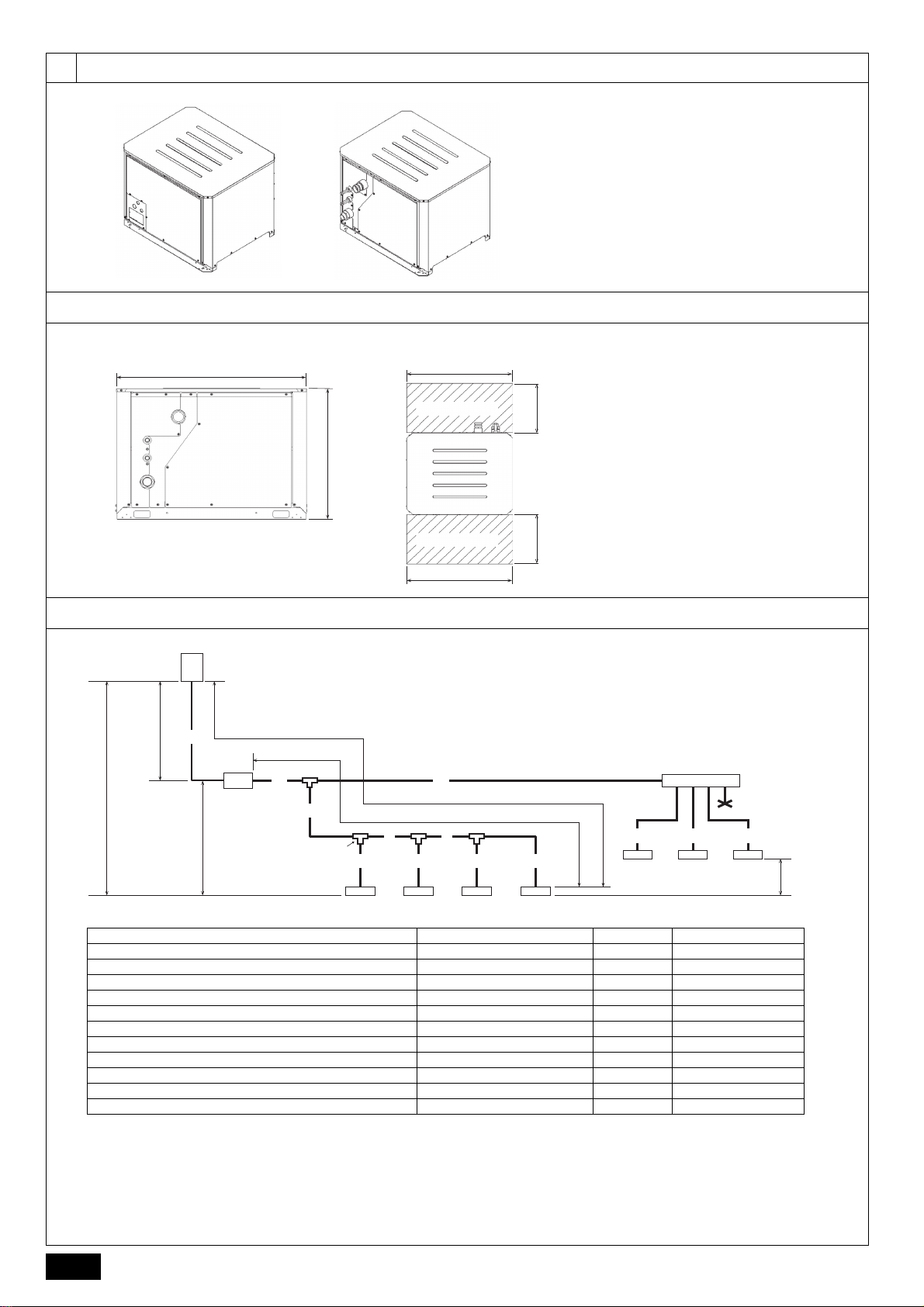
<A> Refrigerant piping side
<B> Water piping side
<A> Front view
<B> Top view
A Service space
A Outdoor unit B 1st branching
C Indoor unit D Hydro unit
E Cap F Joint
G Header branching H Refrigerant piping
I Water piping
(Unit: m)
*1 The maximum length is 90 m, depending on the unit model and installation conditions. For more detailed information, contact your local distributor.
*2 The maximum length is 60 m, depending on the unit model and installation conditions. For more detailed information, contact your local distributor.
Item Piping in the figure Max. length Max. equivalent length
Total piping length A+A'+B+C+D+E+a+b+c+d+e+f+g 1000 Farthest indoor unit from outdoor unit (L1) A+A'+C+D+E+g/A+B+c 165 190
Between outdoor unit and hydro unit (refrigerant pipework) A 110 Farthest indoor unit from hydro unit (L3) A'+C+D+E+g/A'+B+c 60 60
Height between outdoor unit and indoor unit (outdoor unit above indoor unit)
H90-
Height between outdoor unit and indoor unit (outdoor unit below indoor unit)
H' 60 -
Height between outdoor unit and hydro unit (outdoor unit above hydro unit)
H1 50 *1 -
Height between outdoor unit and hydro unit (outdoor unit below hydro unit)
H1' 40 *2 -
Height between hydro unit and indoor unit (hydro unit above indoor unit)
H2 50 -
Height between hydro unit and indoor unit (hydro unit below indoor unit)
H2' 40 -
Height between indoor units h1 30 -
[Fig. 2.2.1]
<A>
<B>
2.3
[Fig. 2.3.1]
<A> <B>
920
920
[Fig. 2.4.1]
)
)
C
C
below
above
A
A
H (
H' (
)
D
above
A
H1 (
A
)
D
below
A
A
H
H1' (
)
C
above
D
H2 (
D
)
C
below
D
H2' (
A
450450
660
A
920
2.4
I
B
A'
C
F
D E
d e f g
CCCC
B
L1
L3
a
CCC
G
E
b c
h1
2
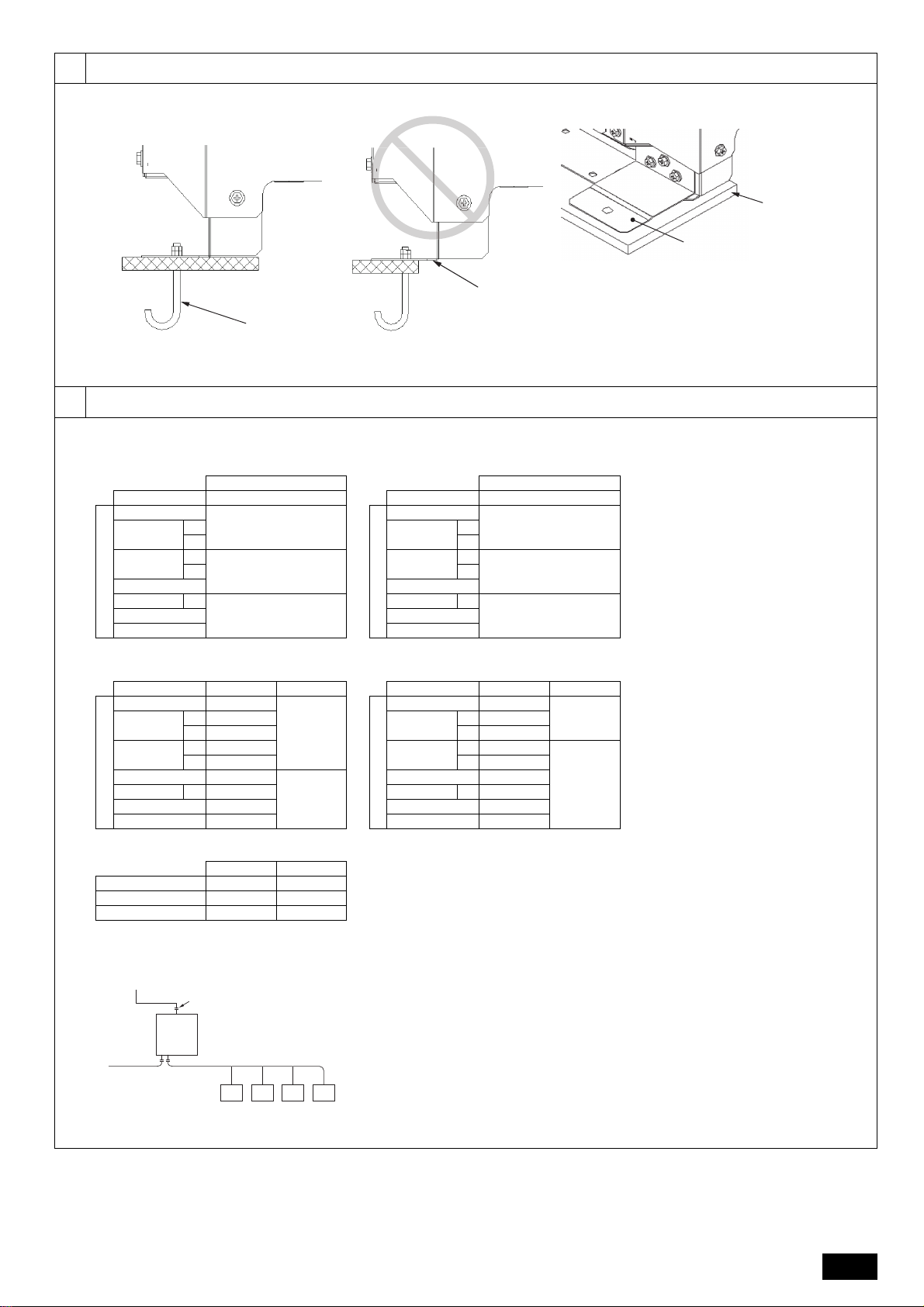
33.2
A M10 anchor bolt (not supplied)
B (Incorrect installation) The corner section is not securely received.
C Fixing bracket for post-installed anchor bolts (not supplied) (To be
fixed with three screws)
D Anti-vibration rubber pad (The pad needs to be large enough to
cover the entire width of each unit leg.)
*1 When the piping length from the outdoor unit to the hydro unit is less than
90 m (295 ft)
*2 When the piping length from the outdoor unit to the hydro unit is
90 m (295 ft) or more
*3 When the piping length from the outdoor unit to the hydro unit is less than
40 m (131 ft)
*4 When the piping length from the outdoor unit to the hydro unit is
40 m (131 ft) or more
*5 When the unit is used alone
A To outdoor unit
B End connection (brazing)
C Hydro unit
D To main piping
E Indoor unit
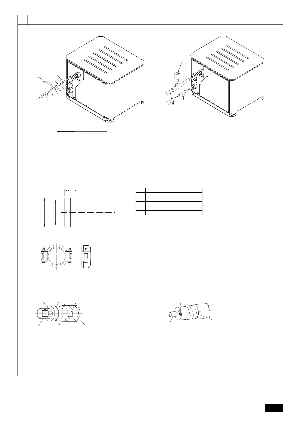
1. Hydro units connectable to outdoor units
Standard models High-efficient models
2. Connecting pipe diameter of outdoor unit
Standard models High-efficient models
3. Connecting pipe diameter of hydro unit
If the connecting pipe diameter of hydro unit differs
from that of outdoor unit, expand or reduce the pipe
diameter at the inlet of the hydro unit.
Hydro unit
Unit model Model name
Outdoor unit side
PUHY-M200
CMH-WM250V-A
PUHY-M250
*1
*2
PUHY-M300
*3
CMH-WM350V-A*4
PUHY-M350
PUHY-M400 *5
CMH-WM500V-APUHY-M450
PUHY-M500
Hydro unit
Unit model Model name
Outdoor unit side
PUHY-EM200
CMH-WM250V-A
PUHY-EM250
*1
*2
PUHY-EM300
*3
CMH-WM350V-A*4
PUHY-EM350
PUHY-EM400 *5
CMH-WM500V-APUHY-EM450
PUHY-EM500
Unit model Liquid Gas
Outdoor unit side
PUHY-M200 ø9.52 (ø3/8)
ø22.2
(ø7/8)
PUHY-M250
*1 ø9.52 (ø3/8)
*2 ø12.7 (ø1/2)
PUHY-M300
*3 ø9.52 (ø3/8)
*4 ø12.7 (ø1/2)
PUHY-M350 ø12.7 (ø1/2)
ø28.58
(ø1-1/8)
PUHY-M400 *5 ø12.7 (ø1/2)
PUHY-M450 ø15.88 (ø5/8)
PUHY-M500 ø15.88 (ø5/8)
Unit model Liquid Gas
Outdoor unit side
PUHY-EM200 ø9.52 (ø3/8)
ø22.2
(ø7/8)
PUHY-EM250
*1 ø9.52 (ø3/8)
*2 ø12.7 (ø1/2)
PUHY-EM300
*3 ø9.52 (ø3/8)
ø28.58
(ø1-1/8)
*4 ø12.7 (ø1/2)
PUHY-EM350 ø12.7 (ø1/2)
PUHY-EM400 *5 ø12.7 (ø1/2)
PUHY-EM450 ø15.88 (ø5/8)
PUHY-EM500 ø15.88 (ø5/8)
Liquid Gas
CMH-WM250V-A ø9.52 (ø3/8) ø22.2 (ø7/8)
CMH-WM350V-A ø12.7 (ø1/2) ø25.4 (ø1)
CMH-WM500V-A ø15.88 (ø5/8) ø25.4 (ø1)
[Fig. 3.2.1]
D
C
B
A
44.1
[Fig. 4.1.1]
A
B
C
D
EEEE
3
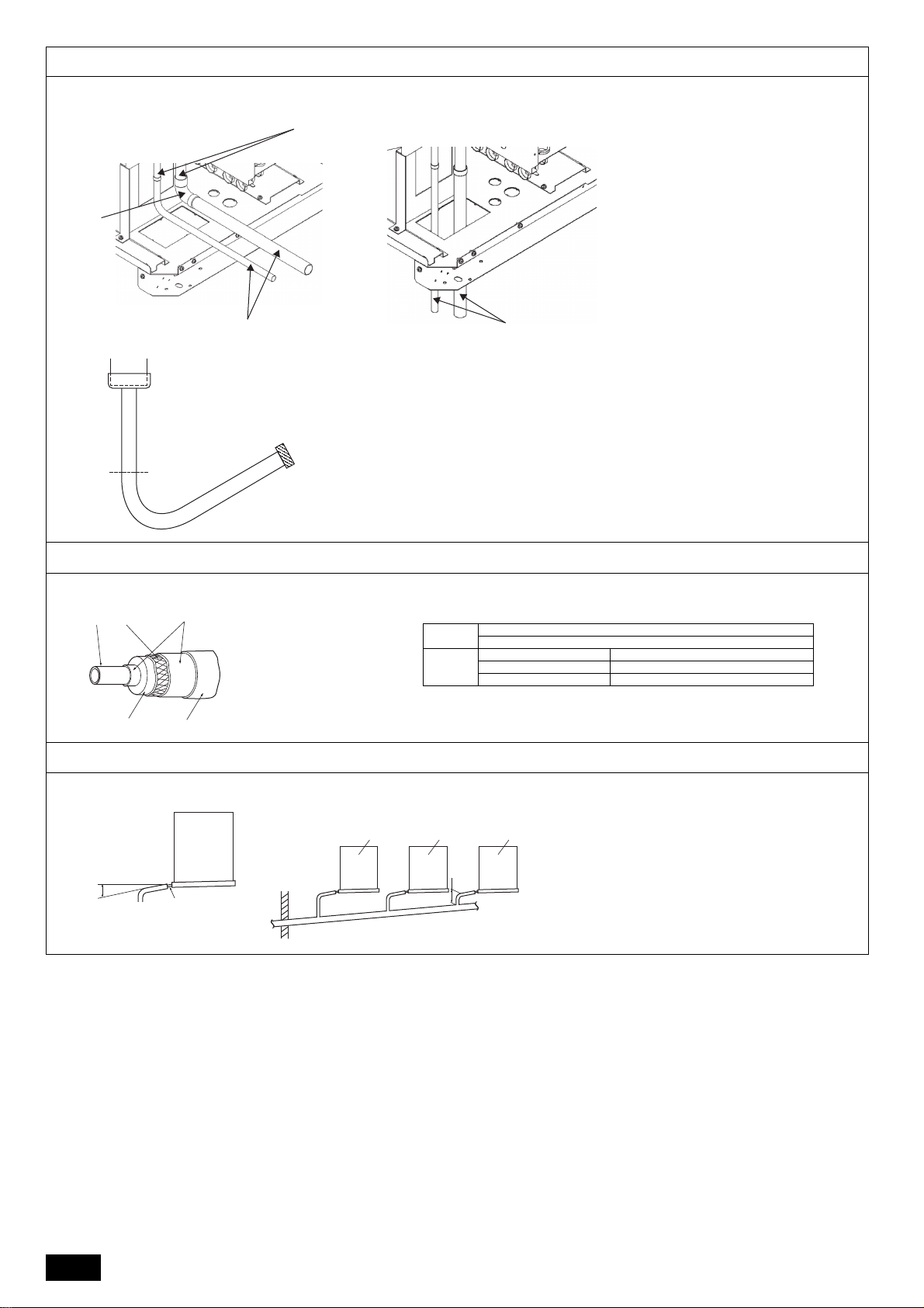
[Fig. 4.1.2]
(1) When routing the pipes through the front of the unit (2) When routing the pipes through the bottom of the unit
(3) Pipe connection port and connecting pipe
C
C
<A> Liquid side
<B> Gas side
A Refrigerant piping
B Elbow
C On-site piping
A Steel w ire
B pipe
C Oily mastic asphalt or asphalt
D Insulation material A
E Outer covering B
* If a polyethylene cover is used as an outer covering, asphalt roofing is not necessary.
Insulation
material A
Glass fiber + Steel wire
Adhesive + Heat-resistant polyethylene foam + Adhesive tape
Outer
covering B
Indoor Vinyl tape
Under the floor and exposed Waterproof hemp cloth + Bronze asphalt
Outdoor Waterproof hemp cloth + Zinc plate + Oily paint
A Downward slope 1/100 or more
B Drain hose
C Unit
D Collective piping
E Maximize this length to approx. 10 cm
* A drain pan is separately sold (for indoor use only).
4.1
B
[Fig. 4.3.1]
<A> <B>
A
<A> <B>
4.3
Ⓑ
Ⓐ
Ⓓ
Ⓒ
Ⓔ
4.4
[Fig. 4.4.1]
C
A
B
1
D
C
E
C
2
4
55.1
Hydro unit sample installation
A Expansion vessel (not supplied) B Pressure gauge (not supplied)
C Check valve (not supplied) D Shutoff valve (not supplied)
E Pressure reducing valve (not supplied) F Strainer (not supplied)
G Water inlet H Auto air vent valve (supplied)
I Strainer (supplied) J Water pipe s
(*1)
Note:
*1. Connect the pipes to the water pipes according to the local regulations.
Pipe size
40A 50A
d ø48.6 ø60.3 ± 0.61
G ø44.8 ø57.15
W 8 ± 0.5 7.95 ± 0.76
L 15 15.88 ± 0.76
+0
-0.7
+0
-0.38
+0.8
-0
A #7K tar felt
B Steel wire
C Blown asphalt
D Base paper
E Pipe
F Glass wool
(Note: Absorbent material)
G Asphalt felt
H Cotton tape (After wrapping it
around a pipe, brush polyester
synthetic resin over the tape.)
[Fig. 5.2.1]
[Fig. 5.2.2]
A Adhesive (Completely fill joints of foam polystyrene pipe insulation and a gap
between a pipe and foam polystyrene pipe insulation with adhesive.)
B Pipe
C Form polystyrene pipe insulation (Non-absorbent material)
D Exterior (When pipes are installed on a roof, cover the pipes with galvanized
steel sheets to protect the pipes from rainwater. This countermeasure is unnecessary when pipes are installed inside.)
E Adhesive tape (Ensure that it has sufficient heat resistance so that high hot water
temperature will not lower its adhesion.)
[Fig. 5.1.1]
H
To
G
A
F
E
C
B
D
J
I
[Fig. 5.1.2]
[Fig. 5.1.3]
A
E
L
W
Gd
5.2
B
F
D
C
G
H
C
A
B
C
D
E
5
A
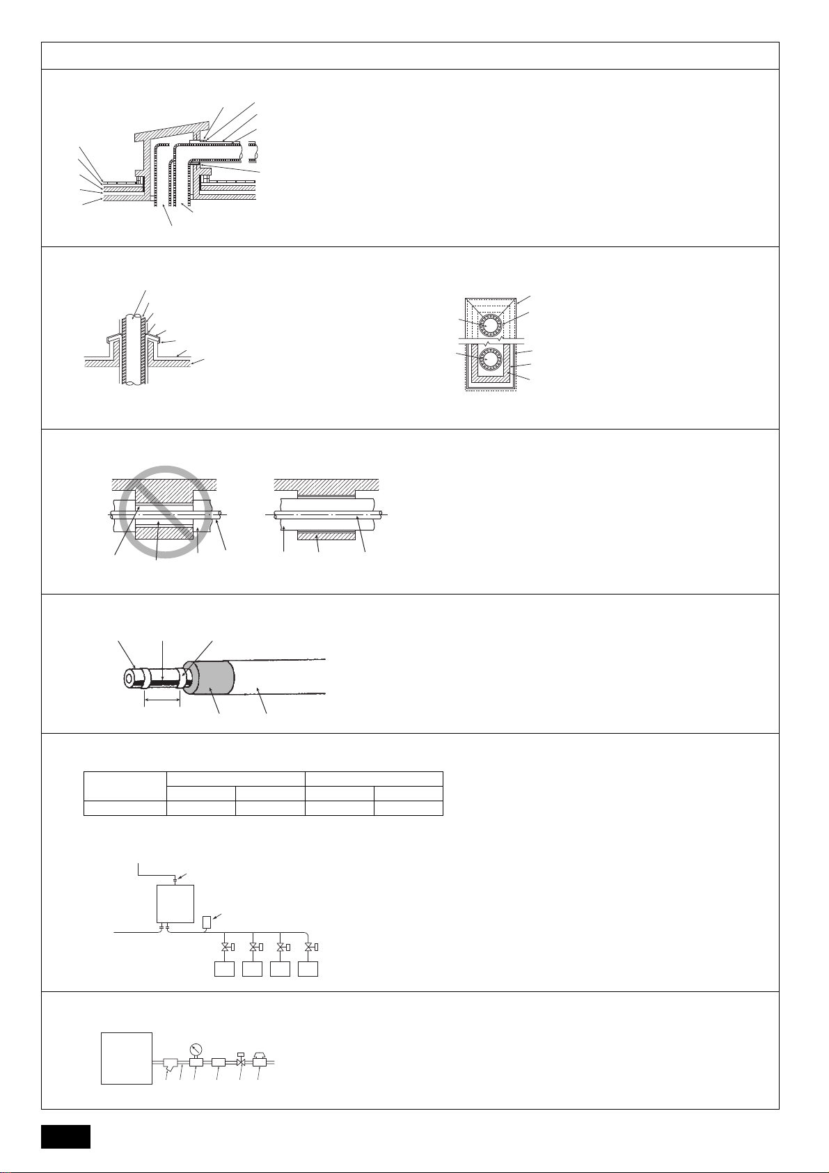
A Finishing mortar (25–30 mm) B Cinder concrete (70–100 mm)
C Two layers of waterproofing membrane (10–12 mm) D Smoothing mortar (25–30 mm)
E Frame concrete F Filled with thermal insulation materials
G Caulking (Waterproof material) H Lagging (Molded paper, waterproof paper, galvanized cast iron
sheet, and paint of a specified color)
I Thermal insulation material (Glass wool or rock wool) J Iron pipe sleeve with collar
Determine the inner diameter of a sleeve in consideration of the
outer diameter of an iron pipe, thickness of thermal insulation,
and thickness of a filler.
K Cold (hot) water pipe (supply pipe) L Cold (hot) water pipe (return pipe)
[Fig. 5.2.3]
A Cold (hot) water pipe (supply and
return pipe)
B Thermal insulation material
C Lagging (covering with galvanized
steel sheet)
D Soldering
E Galvanized steel sheet cover
F Caulking (waterproof material)
elastomeric sealant
G Mortal waterproofing membrane
(30–100 mm)
H Concrete (150 mm)
A Cold (hot) water pipe (supply pipe)
B Bind here using band or tape.
C Galvanized steel sheet cover
D Soldering
E Caulking (waterproof material)
elastomeric sealant
F Mortal waterproofing membrane
G Concrete (150 mm)
B
A Sleeve
B No thermal insulation
C Thermal insulation materials
D Pipe
[Fig. 5.2.5]
Thermal and cold insulation work on a pipe penetrating through a beam
[Fig. 5.2.6]
A Pipe
B Heater
C Adhesive tape
D Insulating material
E Covering material
[Fig. 5.2.7]
Indoor unit
Connection size Pipe size
Water inlet Water outlet Water return Water out
PEFY-W·VMA O.D. 22.0 mm O.D. 22.0 mm I.D. 20 mm I.D. 20 mm
A To outdoor unit
B End connection
C Hydro unit
D To main piping
E Indoor unit
F Auto air vent valve (Highest point on the water pipe) (supplied)
* For other indoor units, refer to the indoor unit installation manual.
* The pipe diameter depends on the capacity of indoor units.
Refer to the indoor unit installation manual for details.
[Fig. 5.2.8]
A Hydro unit
B Strainer (supplied)
C Water pipe
D Pressure gauge (not supplied)
E Check valve (not supplied)
F Shutoff valve (not supplied)
G Pressure reducing valve (not supplied)
B
C
D
E
[Fig. 5.2.4]
5.2
G
F
H
I
J
K
L
A
B
C
D
E
F
G
H
A
B
C
D
E
F
G
A
A
B
250 mm
D
C
C
DE
C
AD
A
B
C
F
D
EEEE
6
A
B GDC FE
 Loading...