

Mitsubishi Electric City Multi CMB-WP108V-G Installation Manual

Air-Conditioners For Building Application
INDOOR UNIT
CMB-WP108V-G
GB
INSTALLATION MANUAL
For safe and correct use, please read this installation manual thoroughly before installing the air-conditioner unit.
2
22.2 2.3
2.4
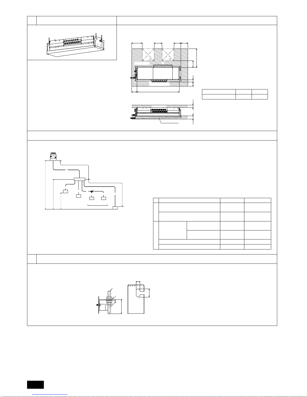
[Fig. 2.4.1]
33.2
[Fig. 3.2.1]
[Fig. 2.2.1]
C
D
E
B
B
E
AA
H Indoor unit side
G Service space
GService space
(FSub drain pan)
(700)
250120 100
*1
89
A200
B265
450 450
300400
<B>
<A>
G Service space
[Fig. 2.3.1]
<A> Top view
<B> Front view
Model name A B
CMB-WP108V-G 1600 –
*1 Dimensions with which pipe connection can be handled at site
A Inspection hole
B Side of outdoor unit piping
C Control box
D Side of indoor unit piping
E Water inlet
F Sub drain pan
G Service space
H Indoor unit side
C
C
CC
I
C
E
A
B
G
H
F
D
J
K
D
A
c
def
b
a
H
H1
h1
h2
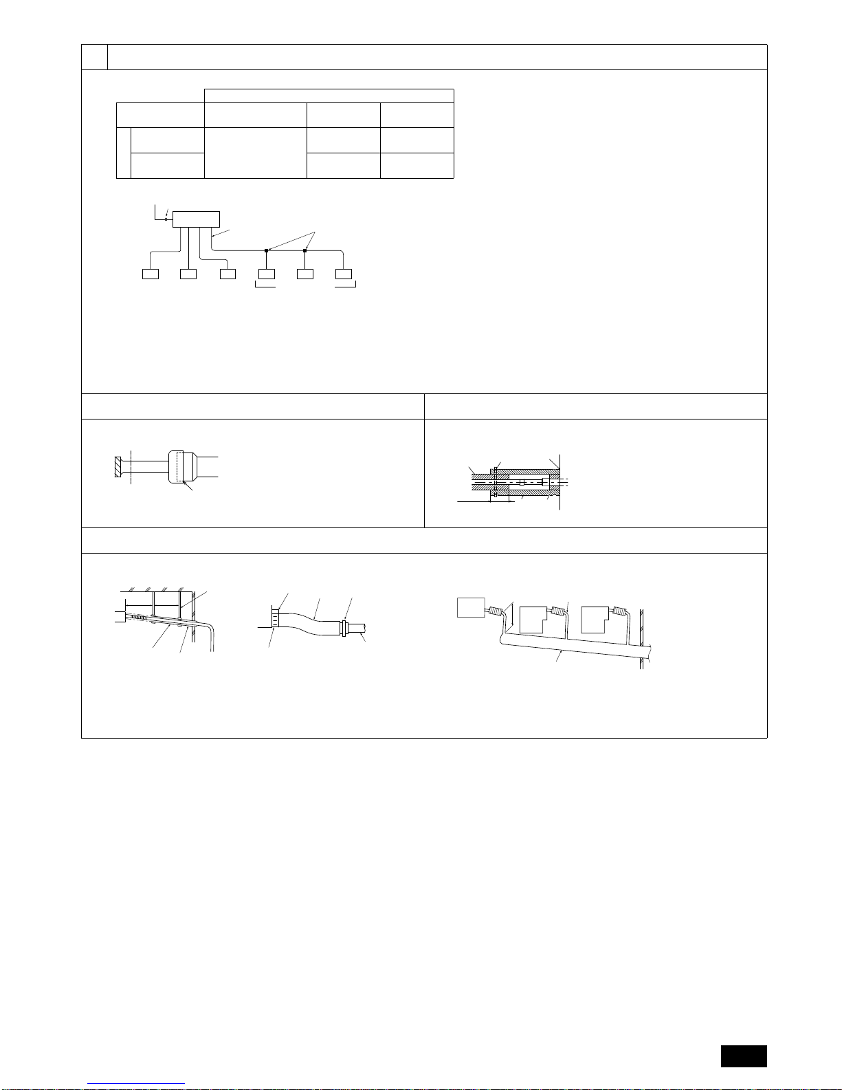
A Outdoor unit B HBC controller
C Indoor unit
D Less than H=50 m (when the outdoor unit is higher than the indoor unit)
E Less than H1=40 m (when the outdoor unit is lower than the indoor unit)
F Twinning pipe (field supply)
G Less than 110 m H Less than 60 m
I Up to three units for 1 branch port
Total capacity: less than 80 (but in same mode, cooling/heating)
J Less than 15 m K Less than 15 m
CMB-WP108V-G
Notes:
*1 Indoor units that are connected to the same branch joint cannot be si-
multaneously operated in different operation modes.
(Unit: m)
Item Piping portion Allowable value
Between outdoor unit and
HBC controller (refrigerant pipework)
A 1 10 or less
Water pipework between indoor units
and HBC controller
f 60 or less
Between
indoor and
outdoor units
Above outdoor unit H 50 or less
Below outdoor unit H1 40 or less
Between indoor units and HBC controller h1 15 or less
Between indoor units h2 15 or less
Pipe Lengths
Difference of ele vat ion
<Top view>
1
B
A
14
30
A
1 Hanging method
A: Min. 30 mm
A Hanging bolt ø10 (field supply)
B Washer (field supply)
3
44.1
[Fig. 4.1.2]
4.2 4.3
[Fig. 4.2.1] [Fig. 4.3.1]
4.4
[Fig. 4.4.1] [Fig. 4.4.2]
D
DD
DDFD
A
B
E
*1
C
HBC CONTROLLER
Unit model Model name
High pressure
side
Low pressure
side
PURY-WP200
(HBC CONTROLLER)
CMB-WP108V-G
ø15.88
(Brazing)
ø19.05
(Brazing)
PURY-WP250
ø19.05
(Brazing)
ø22.2
(Brazing)
Outdoor unit side
Connection to water circuit by screw
connections
Note:
*1. Connection of multiple indoor units with one connection (or joint pipe)
• Total capacity of connectable indoor units: Less than 80
• Number of connectable indoor units: Maximum 3 Sets
• Twinning pipe is field supplied.
A To outdoor unit
B End connection (brazing)
C HBC controller
D Indoor unit
E Twinning pipe (field supply)
F Up to three units for 1 branch hole; to tal cap acity: below 80 (but same in cooling/
heating mode)
B
A
A Cut here
B Remove brazed cap
E
D
A
C
B
F
A Locally procured insulating material
for pipes
B Bind here using band or tape.
C Do not leave any opening.
D Lap margin: more than 40 mm
E Insulating material (field supply)
F Unit side insulating material
1
A
A
B
C
B
VP-25
2
D
E
G
F
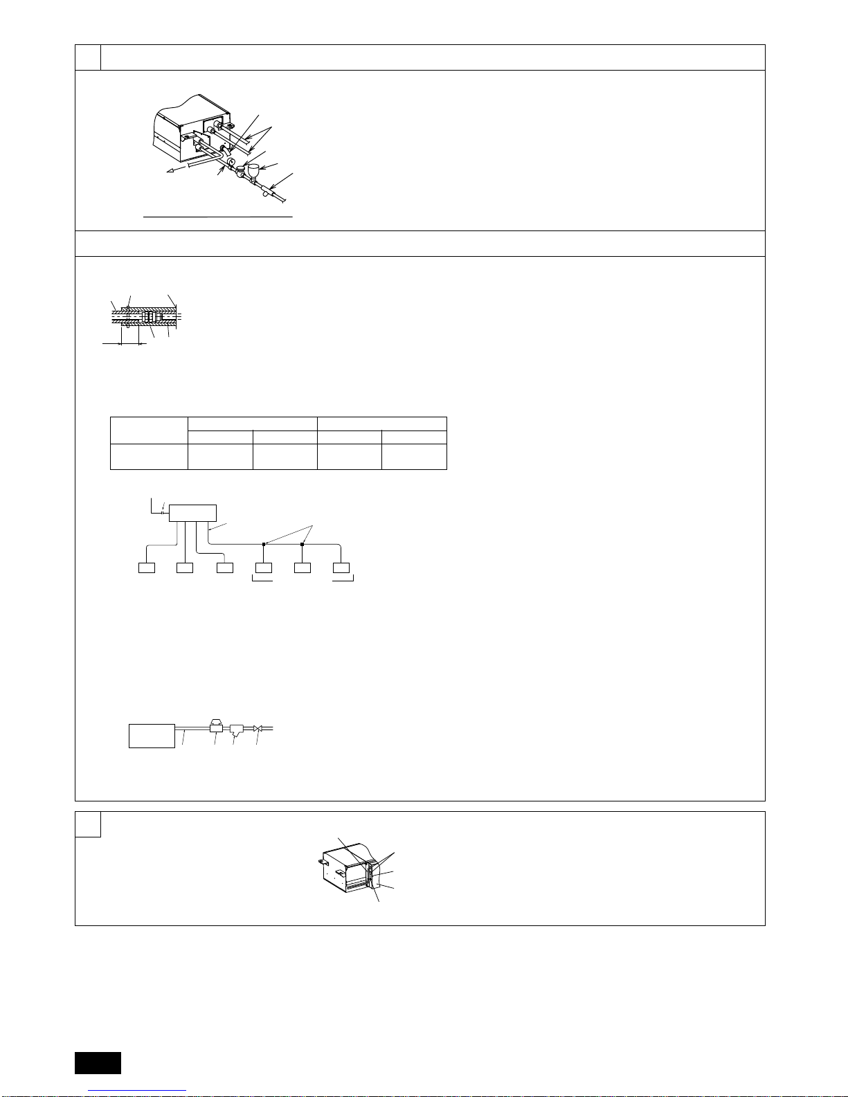
A: 25 cm B: 1.5 – 2 m
A Downward gradient of more than 1/100
B Insulating material C Supporting bracket
D Drain discharge port E Drain hose (200 mm long, accessory)
F Cable tie (accessory) G Hose band (accessory)
BB
A
D
3
C
VP-30
A HBC controller B Indoor unit
C Collecting pipe D Please ensure this length is at least 10 cm.
4
55.1
[Fig. 5.1.1]
5.2
6
E
C
D
B
F
G
ATo
HBC controller sample installation
A Expansion tank B Shutoff valve
C Strainer D Pressure reducing valve
E Water inlet F Refrigerant pipes
G Drain pipe
F
E
D
C
B
A
D
DD
DDFD
A
B
E
*1
C
B C ED
A
A Locally procured insulating material
for pipes
B Bind here using band or tape.
C Do not leave any opening.
D Lap margin: more than 40mm
E Insulating material (field supply)
F Unit side insulating material
A To ou tdoor unit
B End connection (brazing)
C HBC controller
D Indoor unit
E Twinning pipe (field supply)
F Up to three units for 1 branch hole; total capacity: below 80 (but in same mode,
cooling/heating)
Water pipework is screw
connections
Note:
*1. Connection of multiple indoor units with one connection (or joint pipe)
• Total capacity of connectable indoor units: Less than 80
• Number of connectable indoor units: Maximum 3 Sets
• Selection of water piping
Select the size according to the total capacity of indoor units to be installed
downstream.
• Please group units that operate on 1 branch.
[Fig. 5.2.2]
[Fig. 5.2.3]
[Fig. 5.2.1]
A HBC controller
B Water pipe
C Pressure reducing valve
D Strainer
E Shut off valve
Indoor unit
Connection size Pipe size
Water inlet Water outlet Water out Water return
PEFY-WP·VMA
Rc 3/4
screw
Rc 3/4
screw
I.D. 20 mm I.D. 20 mm
E
A
B
C
D
A Control box
B Power source wiring
C ø21 hole (closed rubber bushing)
D Transmission wiring
E Clip cables here
[Fig. 6.0.1]
 Loading...