

Mitsubishi Electric CITY MULTI CMB-WP108V-GA1, CITY MULTI CMB-WP1016V-GB1, CITY MULTI CMB-WP1016V-GA1, CITY MULTI CMB-WP108V-GB1 Installation Manual
Air-Conditioners For Building Application
INDOOR UNIT
CMB-WP108V-GA1, CMB-WP1016V-GA1
CMB-WP108V-GB1, CMB-WP1016V-GB1
GB
INSTALLATION MANUAL
For safe and correct use, please read this installation manual thoroughly before installing the air-conditioner unit.
MANUEL D’INSTALLATION
Veuillez lire le manuel d’installation en entier avant d’installer ce climatiseur pour éviter tout accident et vous assurer d’une utilisation correcte.
DFEI
INSTALLATIONSHANDBUCH
Zum sicheren und ordnungsgemäßen Gebrauch der Klimageräte das Installationshandbuch gründlich durchlesen.
MANUAL DE INSTALACIÓN
Para un uso seguro y correcto, lea detalladamente este manual de instalación antes de montar la unidad de aire acondicionado.
MANUALE DI INSTALLAZIONE
Per un uso sicuro e corretto, leggere attentamente questo manuale di installazione prima di installare il condizionatore d’aria.
NLRU
INSTALLATIEHANDLEIDING
Voor een veilig en juist gebruik moet u deze installatiehandleiding grondig doorlezen voordat u de airconditioner installeert.
РУКОВОДСТВО ПО УСТАНОВКЕ
Для осторожного и правильного использования прибора необходимо тщательно ознакомиться с данным руководством по установке до
выполнения установки кондиционера.
Air-Conditioners For Building Application
INDOOR UNIT
CMB-WP108V-GA1, CMB-WP1016V-GA1
CMB-WP108V-GB1, CMB-WP1016V-GB1
<ORIGINAL>
2
22.2 2.3
2.4
[Fig. 2.4.1]
[Fig. 2.4.2]
[Fig. 2.2.1]
450□450□
AA
Service space
Indoor unit side
(700)
B
B 300
250
A
100120 200
F
D
C
Service space
F
G
Service space
F
Service space
F
B
E
<B>
<A>
[Fig. 2.3.1]
<A> Top view
<B> Front view
Model name A B
CMB-WP108V-GA1 1520 160
CMB-WP1016V-GA1 1800 300
CMB-WP108V-GB1 1520 160
CMB-WP1016V-GB1 1520 160
*1 Dimensions with which pipe connection can be handled at site
A Inspection hole
B Side of outdoor unit piping
C Control box
D Side of indoor unit piping
E Water inlet
F Service space
G Indoor unit side
D
D
DD
J
D
A
B
I
G
K
L
C
H
FE
A
c
de
b
a
h1
h2
f
g
HH1
A Outdoor unit B Main-HBC controller
C Sub-HBC controller D Indoor unit
E Less than H=50 m (when the outdoor unit is higher than HBC)
F Less than H1=40 m (when the outdoor unit is lower than HBC)
G Twinning pipe (field supply)
H Less than 110 m I Less than 60 m
J Up to three units for 1 branch port
Total capacity: less than 80 (but in same mode, cooling/heating)
K Less than 15 m L Less than 15 m
CMB-WP108V-GA1 + CMB-WP108V-GB1
(
CMB-WP1016V-GA1
) (
CMB-WP1016V-GB1
)
Notes:
*1 Indoor units that are connected to the same branch joint cannot be si-
multaneously operated in different operation modes.
(Unit: m)
Item Piping portion Allowable value
Between outdoor unit and
HBC controller (refrigerant pipework)
A 110 or less
Water pipework between indoor units
and HBC controller
f + g 60 or less
Between
indoor and
outdoor units
Above outdoor unit H 50 or less
Below outdoor unit H1 40 or less
Between indoor units and HBC controller h1 15 or less
Between indoor units h2 15 or less
Pipe Lengths
Difference of elevation
C
J
D
A
B
B
H
I
G
K
L
D
D
DD
M
D
FE
G
A
c
de
f
b
a
h1
h2
g
h3
HH1
B
A Outdoor unit B Main-HBC controller
C Sub-HBC controller D Indoor unit
E Less than H=50 m (when the outdoor unit is higher than the indoor unit)
F Less than H1=40 m (when the outdoor unit is lower than the indoor unit)
G Twinning pipe (field supply)
H Less than 110 m I Less than 60 m
J Up to three units for 1 branch port
Total capacity: less than 80 (but in same mode, cooling/heating)
K Less than 15 m L Less than 15 m
M Less than 15 m
CMB-WP108V-GA1 + CMB-WP108V-GB1
(
CMB-WP1016V-GA1
) (
CMB-WP1016V-GB1
)
(Unit: m)
Item Piping portion Allowable value
Between outdoor unit and
HBC controller (refrigerant pipework)
A 110 or less
Water pipework between indoor units
and HBC controller
f + g 60 or less
Between HBC controllers B 40 or less
Between
indoor and
outdoor units
Above outdoor unit H 50 or less
Below outdoor unit H1 40 or less
Between indoor units and HBC controller h1 15 or less
Between indoor units h2 15 or less
Between HBC controllers h3 15 or less
Pipe Lengths
Difference of elevation
3
33.2
[Fig. 3.2.1]
44.1
[Fig. 4.1.2]
4.2
[Fig. 4.2.1]
[Fig. 4.2.2]
<Top view>
1
B
A
14
30
A
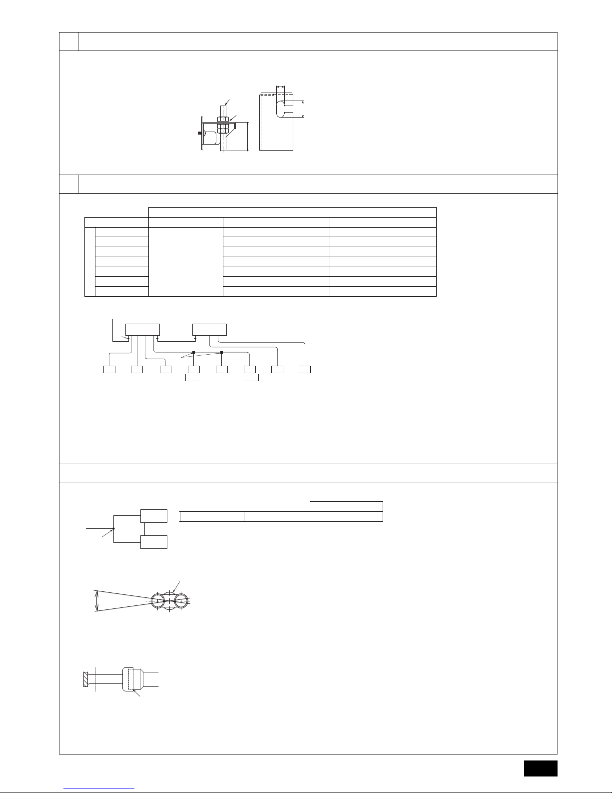
1 Hanging method
A: Min. 30 mm
A Hanging bolt ø10 (field supply)
B Washer (field supply)
E
EE
EEGE E E
A
B
F
*1
C D
HBC CONTROLLER
Unit model Model name High pressure side Low pressure side
PURY-(E)P200
(HBC CONTROLLER)
CMB-WP108V-GA1
CMB-WP1016V-GA1
*2
ø15.88 (Brazing) ø19.05 (Brazing)
PURY-(E)P250 ø19.05 (Brazing) ø22.2 (Brazing)
PURY-(E)P300 ø19.05 (Brazing) ø22.2 (Brazing)
PURY-(E)P350 ø19.05 (Brazing) ø28.58 (Brazing)
PURY-(E)P400 ø15.88 (Brazing) for each HBC ø19.05 (Brazing) for each HBC
PURY-(E)P450 ø15.88 (Brazing) for each HBC ø22.2 (Brazing) for each HBC
PURY-(E)P500 ø19.05 (Brazing) for each HBC ø22.2 (Brazing) for each HBC
Note:
*1. Connection of multiple indoor units with one connection (or joint
pipe)
• Total capacity of connectable indoor units: Less than 80
• Number of connectable indoor units: Maximum 3 Sets
• Twinning pipe is field supplied.
*2. PURY-(E)P-400YLM model or larger requires a connection of two
main-HBC controllers in parallel.
A To outdoor unit
B End connection (brazing)
C Main-HBC controller
D Sub-HBC controller
E Indoor unit
F Twinning pipe (field supply)
G Up to three units for 1 branch hole; total capacity: below 80 (but same in cooling/
heating mode)
Outdoor unit side
HBC 1
HBC 2
A
A
B
Slope of twinning pipes (high-pressure side and low-pressure side)
Make sure the slope of the twinning pipes are at an angle within ±15° to the ground.
If the slope exceeds the specified angle, it may cause lack of capacity.
Pipe size
HBC controller 1 HBC controller 2 ø15.88 (Brazing)
±15°
C
*1
A Main-HBC controller
B Twinning pipe (field supply)
C Slope of the twinning pipe is at an angle within ±15° to the ground
Note:
*1. Straight run of pipe connecting twinning pipe is 500 mm or more.
B
A
A Cut here
B Remove brazed cap
4
44.3
[Fig. 4.3.1]
4.4
[Fig. 4.4.1] [Fig. 4.4.2]
55.1
[Fig. 5.1.1]
[Fig. 5.1.2]
E
D
A
C
B
F
A Locally procured insulating material
for pipes
B Bind here using band or tape.
C Do not leave any opening.
D Lap margin: more than 40 mm
E Insulating material (field supply)
F Unit side insulating material
1
A
A
B
C
B
VP-25
2
D
E
G
F
A: 25 cm B: 1.5 – 2 m
A Downward gradient of more than 1/100
B Insulating material C Supporting bracket
D Drain discharge port E Drain hose (200 mm long, accessory)
F Cable tie (accessory) G Hose band (accessory)
BB
A
D
3
C
VP-30
A Main-HBC controller/Sub-HBC controller
B Indoor unit C Collecting pipe
D Please ensure this length is at least 100 mm.
D
F
B
C
I
H
E
A
G
To
HBC controller sample installation
A Expansion vessel (field supply) B Shutoff valve (field supply)
C Strainer (field supply) D Pressure reducing valve (field supply)
E Water inlet F Refrigerant pipes
G Drain pipe H Pressure gauge (field supply)
I Check valve (field supply)
(*1)
Note:
*1. Connect the pipes to the water pipes according to the local regulations.
A Indoor unit connection
B Cutting point
C Cut the piping at the cutting point
D Field pipe connection (field supply)
E Field pipe
F Pipe connection (field supply)
Note: Remove burr after cutting the piping to prevent entering the pipe con-
nection.
Check that there is no crack at the edge of the piping.
A
B
C
D
E
F
5
55.1
5.2
6
A
B
C
D
EF
A HBC controller
B Sub-HBC controller
C To Sub-HBC controller (Hot water)
D From Sub-HBC controller (Hot water)
E To Sub-HBC controller (Cold water)
F From Sub-HBC controller (Cold water)
[Fig. 5.1.3]
F
E
D
C
B
A
E
EE
EEGE
A
B
F
C D
K
H
J
I
B FCGED
A
A Locally procured insulating material
for pipes
B Bind here using band or tape.
C Do not leave any opening.
D Lap margin: more than 40 mm
E Insulating material (field supply)
F Unit side insulating material
[Fig. 5.2.2]
[Fig. 5.2.3]
[Fig. 5.2.1]
A HBC controller
B Water pipe
C Pressure gauge (field supply)
D Check valve (field supply)
E Shutoff valve (field supply)
F Pressure reducing valve (field supply)
G Strainer (field supply)
Indoor unit
Connection size Pipe size
Water inlet Water outlet Water out Water return
PEFY-WP·VMA
Rc 3/4
screw
Rc 3/4
screw
I.D. 20 mm I.D. 20 mm
A To outdoor unit
B End connection (brazing)
C Main-HBC controller
D Sub-HBC controller
E Indoor unit
F Twinning pipe (field supply)
G Up to three units for 1 branch hole; total capacity: below 80 (but in same mode,
cooling/heating)
H Shutoff valve (field supply)
I Pressure control valve (field supply)
J Auto air vent valve (Highest point on the water pipe) (field supply)
K Water pipew ork
* For other indoor units, refer to the indoor unit installation manual.
A
B
C
D
E
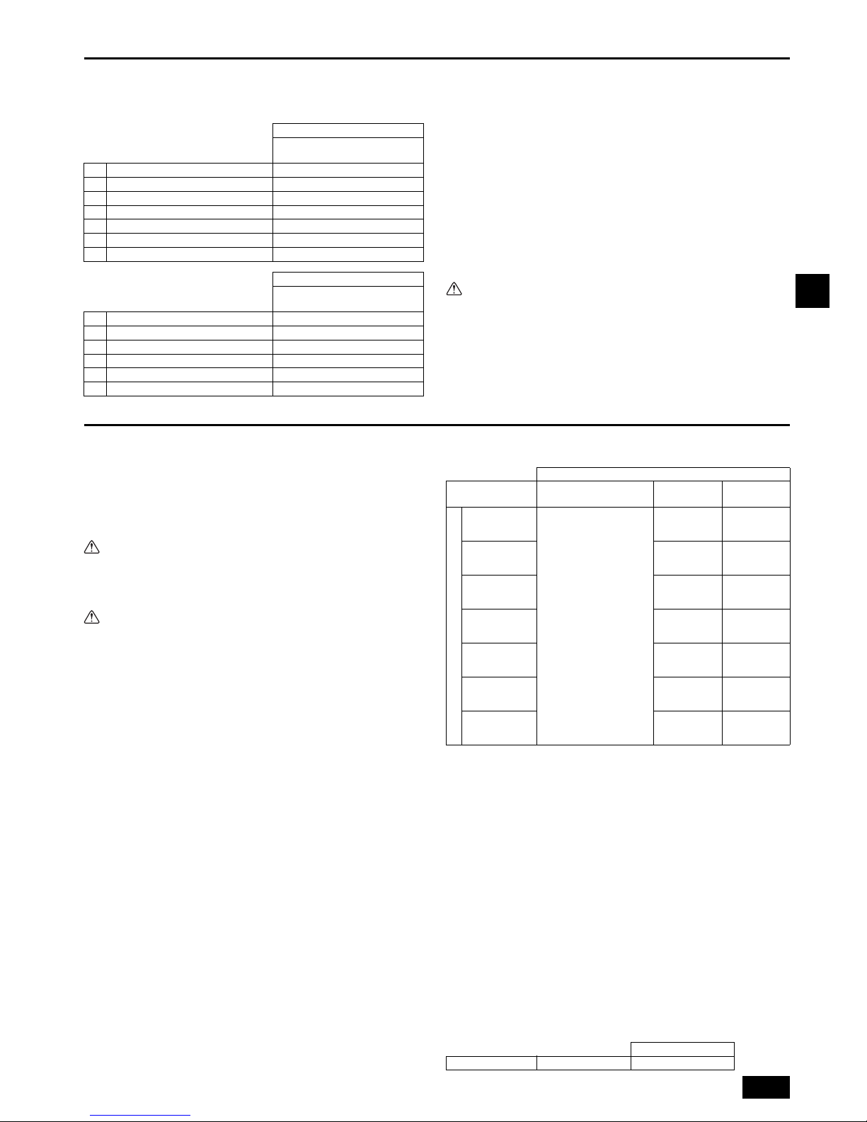
A Control box
B Power source wiring
C ø21 hole (closed rubber bushing)
D Transmission wiring
E Clip cables here
[Fig. 6.0.1]
CMB-WP108V-GA1,CMB-WP1016V-GA1
CMB-WP108V-GB1, CMB-WP1016V-GB1
6
GB
Contents
1. Safety precautions .............................................................................................6
1.1. Before installation and electric work.................................................6
1.2. Precautions for devices that use R410A refrigerant .........................7
1.3. Before installation .............................................................................7
1.4. Before installation (relocation) - electrical work ................................7
1.5. Before starting the test run...............................................................7
2. Selecting an installation site ..............................................................................8
2.1. About the product .............................................................................8
2.2. Installation site..................................................................................8
2.3. Securing installation and service space ...........................................8
2.4. Checking the installation site ............................................................8
3. Installing the HBC controller ..............................................................................9
3.1. Checking the accessories with the HBC controller...........................9
3.2. Installing HBC controllers.................................................................9
4. Connecting refrigerant pipes and drain pipes ....................................................9
4.1. Connecting refrigerant pipes ............................................................9
4.2. Refrigerant piping work ....................................................................9
4.3. Insulating refrigerant pipes.............................................................10
4.4. Drain piping work............................................................................ 10
5. Connecting water pipework .............................................................................11
5.1. Important notes on water pipework installation ..............................11
5.2. Water pipe insulation ......................................................................11
5.3. Water treatment and quality control ...............................................12
6. Electrical work..................................................................................................12
7. Setting addresses and operating units ............................................................12
8. Test run............................................................................................................13
1. Safety precautions
1.1. Before installation and electric work
Symbols used in the text
Warning:
Describes precautions that should be observed to prevent danger of injury or
death to the user.
Caution:
Describes precautions that should be observed to prevent damage to the unit.
Symbols used in the illustrations
HIGH VOLTAGE WARNING:
• Control box houses high-voltage parts.
• When opening or closing the front panel of the control box, do not let it
come into contact with any of the internal components.
• Before inspecting the inside of the control box, turn off the power, keep the
unit off for at least 10 minutes.
Warning:
• Ask the dealer or an authorized technician to install the air conditioner.
- Improper installation by the user may result in water leakage, electric shock, or
fire.
• Install the unit at a place that can withstand its weight.
- Failure to do so may cause the unit to fall down, resulting in injuries and dam-
age to the unit.
• Use the specified cables for wiring. Make the connections securely so that
the outside force of the cable is not applied to the terminals.
- Inadequate connection and fastening may generate heat and cause a fire.
• Prepare for earthquakes and install the unit at the specified place.
- Improper installation may cause the unit to fall down and result in injury and
damage to the unit.
• Always use accessories specified by Mitsubishi Electric.
- Ask an authorized technician to install the accessories. Improper installation by
the user may result in water leakage, electric shock, or fire.
• Never repair the unit. If the air conditioner must be repaired, consult the
dealer.
- If the unit is repaired improperly, water leakage, electric shock, or fire may
result.
• If the supply cord is damaged, it must be replaced by the manufacturer, its
service agent or similarly qualified persons in order to avoid a hazard.
• If refrigerant gas leaks during installation work, ventilate the room.
- If the refrigerant gas comes into contact with a flame, poisonous gases will be
released.
• Install the air conditioner according to this Installation Manual.
- If the unit is installed improperly, water leakage, electric shock, or fire may
result.
• Do not modify or adjust safety protection devices.
- Shorting of pressure or temperature switches to force operation may lead to
damage, fire, explosions etc...
- Do not change the set values as this may lead to damage, fire, explosions etc...
- Use of any product except that specified by this company may lead to damage,
fire, explosions etc...
• Do not spray water on electrical parts.
- This could lead to shorting, fire, smoke, electrical shock, unit failure etc...
• Do not create a situation where the refrigeration circuit is sealed yet incomplete with oil or refrigerant in the system.
- This may result in an explosion.
• Do not touch electrical components during or directly after operation.
- This may lead to burns.
• Put covers on control and terminal boxes.
- Shock due to ingress of dust, water, smoke, fire etc. may result.
• Do not operate with guards or panels removed.
- Injury due to rotating parts, electric shock due to high voltage or burns due to
high temperatures may result.
• Do no sit, ride or place objects on the unit.
- Injury due to the unit falling may result.
• Use the appropriate safety gear.
- High voltages may result in electric shock.
- Hot parts may result in burns.
• Recover the refrigerant in the unit.
- Reuse the refrigerant or have it disposed of by a specialist.
- Release of refrigerant may damage the environment.
• Clear the pipework of remnant gas and oil.
- Failure to do so could lead to an eruption of flames and burns if the pipework is
heated.
• Vacuum dry the refrigerant pipework. Do not replace with a refrigerant that
has not been specified.
- This could lead to explosions, fire.
• Do not touch the onsite pipework ends.
- This could damage the pipework leading to refrigerant leaks and oxygen defi-
ciency.
• Have all electric work done by a licensed electrician according to “Electric
Facility Engineering Standard” and “Interior Wire Regulations” and the
instructions given in this manual and always use a dedicated power supply.
- If the power source capacity is inadequate or electric work is performed
improperly, electric shock and fire may result.
• Securely install the cover of control box.
- If the cover is not installed properly, dust or water may enter the outdoor unit
and fire or electric shock may result.
• When installing and moving the air conditioner to another site, do not
charge it with a refrigerant different from the refrigerant specified on the
unit.
- If a different refrigerant or air is mixed with the original refrigerant, the refriger-
ant cycle may malfunction and the unit may be damaged.
• If the air conditioner is installed in a small room, measures must be taken
to prevent the refrigerant concentration from exceeding the safety limit if
the refrigerant should leak.
- Consult the dealer regarding the appropriate measures to prevent the safety
limit from being exceeded. Should the refrigerant leak and cause the safety
limit to be exceeded, hazards due to lack of oxygen in the room could result.
• When moving and reinstalling the air conditioner, consult the dealer or an
authorized technician.
- If the air conditioner is installed improperly, water leakage, electric shock, or fire
may result.
• After completing installation work, make sure that refrigerant gas is not
leaking.
- If the refrigerant gas leaks and is exposed to a fan heater, stove, oven, or other
heat source, it may generate noxious gases.
Before installing the unit, make sure you read all the “Safety
precautions”.
The “Safety precautions” provide very important points regard-
ing safety. Make sure you follow them.
: Indicates an action that must be avoided.
: Indicates that important instructions must be followed.
: Indicates a part which must be grounded.
: Beware of electric shock. (This symbol is displayed on the main unit label.)
<Color: Yellow>
Warning:
Carefully read the labels affixed to the main unit.

7
GB
• Do not reconstruct or change the settings of the protection devices.
- If the pressure switch, thermal switch, or other protection device is shorted or
operated forcibly, or parts other than those specified by Mitsubishi Electric are
used, fire or explosion may result.
• To dispose of this product, consult your dealer.
• The installer and system specialist shall secure safety against leakage
according to local regulation or standards.
- Choose the appropriate wire size and the switch capacities for the main power
supply described in this manual if local regulations are not available.
• Pay special attention to the place of installation, such as basement, etc.
where refrigeration gas can accumulate, since refrigerant is heavier than
the air.
• This appliance is not intended for use by persons (including children) with
reduced physical, sensory or mental capabilities, or lack of experience and
knowledge, unless they have been given supervision or instruction concerning use of the appliance by a person responsible for their safety.
• Children should be supervised to ensure that they do not play with the
appliance.
1.2. Precautions for devices that use R410A
refrigerant
Caution:
• Do not use existing refrigerant piping.
- The old refrigerant and refrigerant oil in the existing piping contains a large
amount of chlorine which may cause the refrigerant oil of the new unit to deteriorate.
- R410A is a high-pressure refrigerant and can cause the existing piping to burst.
• Use refrigerant piping made of phosphorus deoxidized copper and copper
alloy seamless pipes and tubes. In addition, be sure that the inner and
outer surfaces of the pipes are clean and free of hazardous sulphur,
oxides, dust/dirt, shaving particles, oils, moisture, or any other contaminant.
- Contaminants on the inside of the refrigerant piping may cause the refrigerant
residual oil to deteriorate.
• Store the piping to be used during installation indoors and keep both ends
of the piping sealed until just before brazing. (Store elbows and other joints
in a plastic bag.)
- If dust, dirt, or water enters the refrigerant cycle, deterioration of the oil and
compressor failure may result.
• Apply a small amount of ester oil, ether oil, or alkyl benzene to flares. (for
indoor unit)
- Infiltration of a large amount of mineral oil may cause the refrigerant oil to dete-
riorate.
• Use liquid refrigerant to fill the system.
- If gas refrigerant is used to fill the system, the composition of the refrigerant in
the cylinder will change and performance may drop.
• Do not use a refrigerant other than R410A.
- If another refrigerant (R22, etc.) is mixed with R410A, the chlorine in the refrig-
erant may cause the refrigerant oil to deteriorate.
• Use a vacuum pump with a reverse flow check valve.
- The vacuum pump oil may flow back into the refrigerant cycle and cause the
refrigerant oil to deteriorate.
• Do not use the following tools that are used with conventional refrigerants.
(Gauge manifold, charge hose, gas leak detector, reverse flow check valve,
refrigerant charge base, refrigerant recovery equipment)
- If the conventional refrigerant and refrigerant oil are mixed in the R410A, the
refrigerant may deteriorate.
- If water is mixed in the R410A, the refrigerant oil may deteriorate.
- Since R410A does not contain any chlorine, gas leak detectors for conven-
tional refrigerants will not react to it.
• Do not use a charging cylinder.
- Using a charging cylinder may cause the refrigerant to deteriorate.
• Do not use antioxidant or leak-detection additive.
• Be especially careful when managing the tools.
- If dust, dirt, or water gets into the refrigerant cycle, the refrigerant may deterio-
rate.
1.3. Before installation
Caution:
• Do not install the unit where combustible gas may leak.
- If the gas leaks and accumulates around the unit, an explosion may result.
• Do not use the air conditioner where food, pets, plants, precision instruments, or artwork are kept.
- The quality of the food, etc. may deteriorate.
• Do not use the air conditioner in special environments.
- Oil, steam, sulfuric smoke, etc. can significantly reduce the performance of the
air conditioner or damage its parts.
• When installing the unit in a hospital, communication station, or similar
place, provide sufficient protection against noise.
- Sound pressure level does not exceed 70 dB(A). However, inverter equipment,
private power generator, high-frequency medical equipment, or radio communication equipment may cause the air conditioner to operate erroneously, or fail
to operate. On the other hand, the air conditioner may affect such equipment by
creating noise that disturbs medical treatment or image broadcasting.
• Do not install the unit on or over things that are subject to water damage.
- When the room humidity exceeds 80 % or when the drain pipe is clogged, con-
densation may drip from the indoor unit or HBC controller. Perform collective
drainage work together with the outdoor unit, as required.
1.4. Before installation (relocation) - electri-
cal work
Caution:
• Ground the unit.
- Do not connect the ground wire to gas or water pipes, lightning rods, or tele-
phone ground lines. Improper grounding may result in electric shock.
• Install the power cable so that tension is not applied to the cable.
- Tension may cause the cable to break and generate heat and cause a fire.
• Install a leak circuit breaker, as required.
- If a leak circuit breaker is not installed, electric shock may result.
• Use power line cables of sufficient current carrying capacity and rating.
- Cables that are too small may leak, generate heat, and cause a fire.
• Use only a circuit breaker and fuse of the specified capacity.
- A fuse or circuit breaker of a larger capacity, or the use of substitute simple
steel or copper wire may result in a general unit failure or fire.
• Do not wash the air conditioner units.
- Washing them may cause an electric shock.
• Be careful that the installation base is not damaged by long use.
- If the damage is left uncorrected, the unit may fall and cause personal injury or
property damage.
• Install the drain piping according to this Installation Manual to ensure
proper drainage. Wrap thermal insulation around the pipes to prevent condensation.
- Improper drain piping may cause water leakage causing damage to furniture
and other possessions.
• Be very careful about transporting the product.
- One person should not carry the product. Its weight is in excess of 20 kg.
- Some products use PP bands for packaging. Do not use any PP bands as a
means of transportation. It is dangerous.
• Safely dispose of the packing materials.
- Packing materials, such as nails and other metal or wooden parts, may cause
stabs or other injuries.
- Tear apart and throw away plastic packaging bags so that children will not play
with them. If children play with a plastic bag which has not been torn apart, they
face the risk of suffocation.
1.5. Before starting the test run
Caution:
• Turn on the power at least 12 hours before starting operation.
- Starting operation immediately after turning on the main power switch can
result in irreversible damage to internal parts. Keep the power switch turned on
during the operational season.
• Do not touch the switches with wet fingers.
- Touching a switch with wet fingers can result in an electric shock.
• Do not touch the refrigerant pipes during and immediately after operation.
- During and immediately after operation, the refrigerant pipes may be hot or
cold, depending on the condition of the refrigerant flowing through the refrigerant piping, compressor, and other refrigerant cycle parts. Your hands may suffer burns or frostbite if you touch the refrigerant pipes.
• Do not operate the air conditioner with the panels and guards removed.
- Rotating, hot, or high-voltage parts can cause injuries.
• Do not turn off the power immediately after stopping operation.
- Always wait at least 5 minutes before turning off the power. Otherwise, drain-
age water leakage or mechanical failure of sensitive parts may occur.
8
GB
2. Selecting an installation site
2.1. About the product
• This unit uses R410A-type refrigerant.
• Only the “WP” models of indoor units can be connected.
• Piping for systems using R410A may be different from that for systems using
conventional refrigerant because the design pressure in systems using R410A is
higher. Refer to the Data Book for more information.
• Some of the tools and equipment used for installation with systems that use other
types of refrigerant cannot be used with the systems using R410A. Refer to the
Data Book for more information.
• Do not use the existing piping, as it contains chlorine, which is found in conventional refrigerating machine oil and refrigerant. This chlorine will deteriorate the
refrigerant machine oil in the new equipment. The existing piping must not be
used as the design pressure in systems using R410A is higher than that in the
systems using other types of refrigerant and the existing pipes may burst.
2.2. Installation site
• Install the unit in a place not exposed to rain. The HBC controller is designed to
be installed indoors.
• Install the unit with adequate space around it for servicing.
• Do not install the unit in a place that would result in the piping length restrictions
being exceeded.
• Install the unit in a place not exposed to direct radiant heat from other heat
sources.
• Do not install the unit in any oily steamy place or near any machine that generates high frequencies. Doing so may cause a risk of fire, erroneous operation or
condensation.
• Depending on the operation conditions, HBC unit generates noise caused by
valve actuation, refrigerant flow, and pressure changes even when operating
normally. Therefore install the unit in places such as ceilings of corridor,
restrooms and plant rooms.
• Install indoor unit and HBC controller at least 5 m away from each other when
installed in a space with low background noise, e.g., hotel rooms.
• Allow enough space and access to ensure water piping, refrigerant piping and
electrical wiring can be easily connected.
• Avoid places exposed to the generation, inflow, accumulation or leakage of flammable and sulfuric gases.
• Ensure a downward gradient of at least 1/100 for drain piping.
• Properly install the unit on a stable, load-bearing surface.
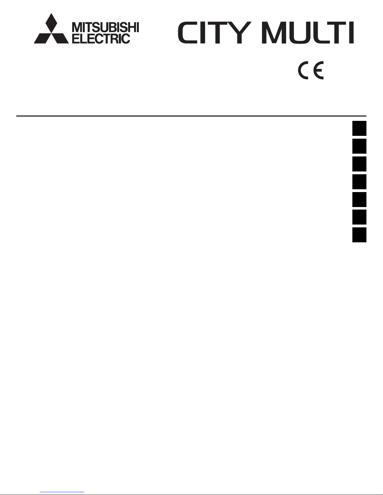
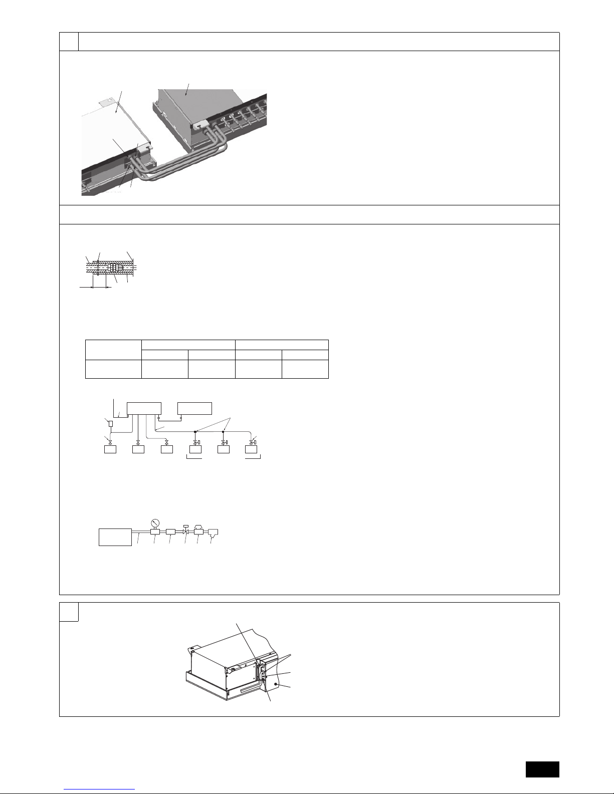
1. For hanging from the ceiling [Fig. 2.2.1] (P.2)
• Provide 2 inspection holes 450 mm square in the ceiling surface as shown in
[Fig. 2.3.1] (P.2).
• Install the unit in a suitable location (such as in the ceiling of a corridor or in the
bathroom etc) away from places regularly occupied. Avoid installing in the center
of a room.
• Ensure hanging bolts are of sufficient pull out strength.
Warning:
Be sure to install the unit in a place that can sustain the entire weight.
If there is a lack of strength, it may cause the unit to fall down, resulting in an
injury.
Caution:
• Be sure to install the unit horizontally.
Install the HBC level (less than 1° tilt), so that the drain pan can function
correctly.
• Install the HBC in an environment where the temperature in always above
0°C.
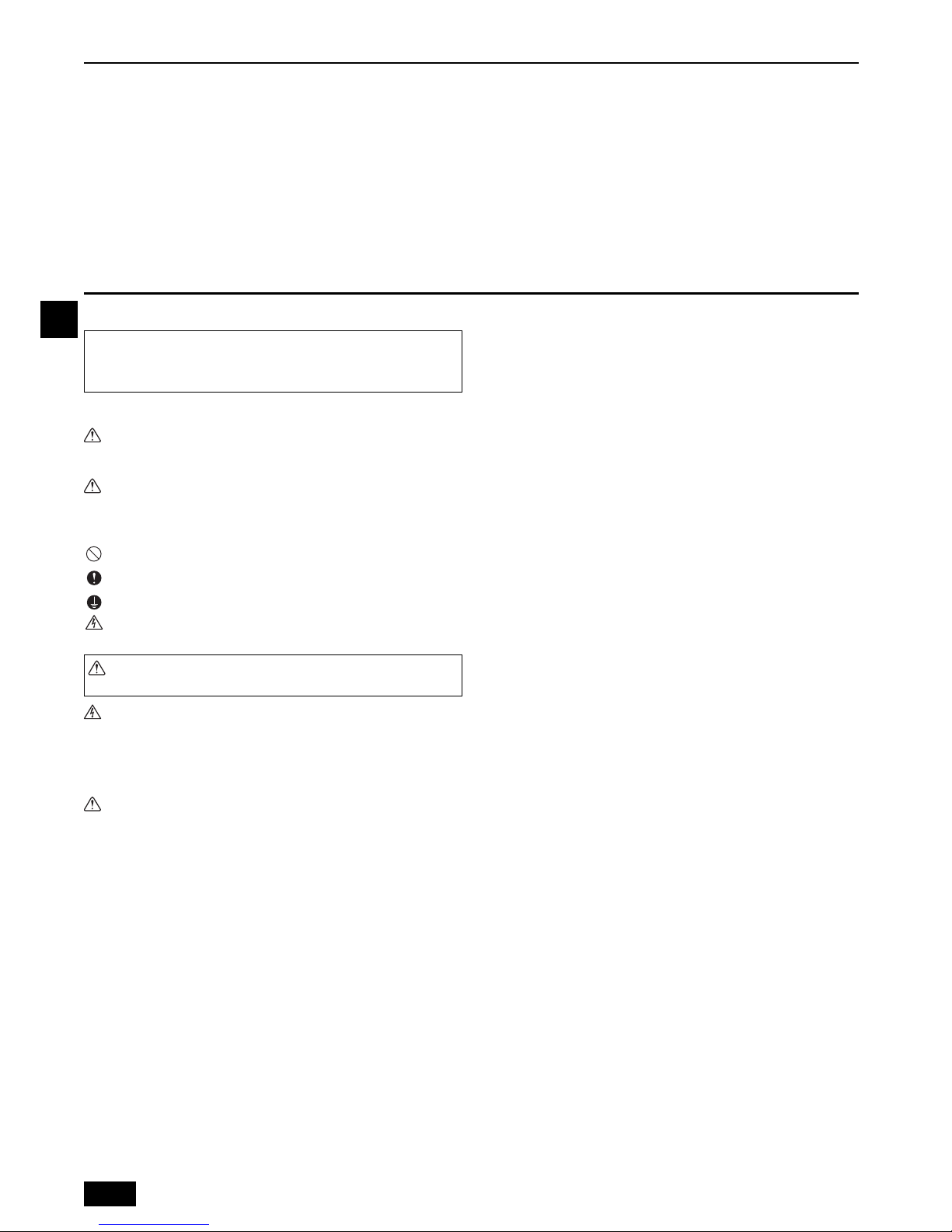
2.3. Securing installation and service space
1. For hanging from the ceiling
(This is a reference view showing the least installation space.)
[Fig. 2.3.1] (P.2)
2.4. Checking the installation site
Check that the difference of elevation between indoor and outdoor units and the
length of refrigerant piping are within the following limitations.
1. CMB-WP108V-GA1 + CMB-WP108V-GB1
(
CMB-WP1016V-GA1
) (
CMB-WP1016V-GB1
)
[Fig. 2.4.1] (P.2)
Notes:
*1 Indoor units that are connected to the same branch joint cannot be simul-
taneously operated in different operation modes.
2. CMB-WP108V-GA1 + CMB-WP108V-GB1
(
CMB-WP1016V-GA1
) (
CMB-WP1016V-GB1
)
[Fig. 2.4.2] (P.2)
<A> Top view <B> Front view
A Inspection hole B Side of outdoor unit piping
C Control box D Side of indoor unit piping
E Water inlet F Service space
G Indoor unit side
*1 Dimensions with which pipe connection can be handled at site
Model name A B
CMB-WP108V-GA1 1520 160
CMB-WP1016V-GA1 1800 300
CMB-WP108V-GB1 1520 160
CMB-WP1016V-GB1 1520 160
A Outdoor unit B Main-HBC controller
C Sub-HBC controller D Indoor unit
E Less than H=50 m (when the outdoor unit is higher than HBC)
F Less than H1=40 m (when the outdoor unit is lower than HBC)
G Twinning pipe (field supply)
H Less than 110 m I Less than 60 m
J Up to three units for 1 branch port
Total capacity: less than 80 (but in same mode, cooling/heating)
K Less than 15 m L Less than 15 m
(Unit: m)
Item Piping portion Allowable value
Between outdoor unit and HBC
controller (refrigerant pipework)
A 110 or less
Water pipework between indoor units and
HBC controller
f + g 60 or less
Between
indoor and
outdoor units
Above outdoor unit H 50 or less
Below outdoor unit H1 40 or less
Between indoor units and HBC controller h1 15 or less
Between indoor units h2 15 or less
A Outdoor unit B Main-HBC controller
C Sub-HBC controller D Indoor unit
E Less than H=50 m (when the outdoor unit is higher than the indoor unit)
F Less than H1=40 m (when the outdoor unit is lower than the indoor unit)
G Twinning pipe (field supply)
H Less than 110 m I Less than 60 m
J Up to three units for 1 branch port
Total capacity: less than 80 (but in same mode, cooling/heating)
K Less than 15 m L Less than 15 m
M Less than 15 m
(Unit: m)
Item Piping portion Allowable value
Between outdoor unit and
HBC controller (refrigerant pipework)
A 110 or less
Water pipework between indoor units
and HBC controller
f + g 60 or less
Between HBC controllers B 40 or less
Between
indoor and
outdoor units
Above outdoor unit H 50 or less
Below outdoor unit H1 40 or less
Between indoor units and HBC controller h1 15 or less
Between indoor units h2 15 or less
Between HBC controllers h3 15 or less
Pipe Lengths
Difference of elevation
Pipe Lengths
Difference of elevation
9
GB
3. Installing the HBC controller
3.1. Checking the accessories with the HBC
controller
The following items are supplied with each HBC controller.
3.2. Installing HBC controllers
Installing hanging bolts
Install locally procured hanging bolts (threaded rod) following the procedure given in
the figure. The hanging bolt size is ø10 (M10 screw).
To hang the unit, use a lifting machine to lift and pass it through the hanging bolts.
The suspension bracket has an oval hole. Use a large diameter washer.
[Fig. 3.2.1] (P.3)
Be sure to install the HBC controller horizontally. Check using a level. If
the controller is installed at an angle, drain water may leak out. If the unit
is slanted, loosen the fixing nuts on the hanging brackets to adjust its
position.
Install the HBC level (less than 1° tilt), so that the drain pan can function
correctly.
Caution:
• Be sure to install the unit horizontally.
Install the HBC level (less than 1° tilt), so that the drain pan can function
correctly.
4. Connecting refrigerant pipes and drain pipes
4.1. Connecting refrigerant pipes
1. Be sure to use non-oxidative brazing where necessary. If you do not use non-oxidative brazing, it may clog the pipes.
When brazing the outdoor unit connecting port of HBC controller, supply nitrogen
gas into the pipe between the outdoor unit and HBC controller.
2. After completing pipe connection, support the pipes to ensure that load is not
imparted to the HBC controller’s end connections.
Warning:
When installing and moving the unit, do not charge it with refrigerant other
than the refrigerant (R410A) specified on the unit.
- Mixing of a different refrigerant, air, etc. may cause the refrigerant cycle to mal-
function and result in severe damage.
Caution:
• Use refrigerant piping made of phosphorus deoxidized copper and copper
alloy seamless pipes and tubes. In addition, be sure that the inner and outer
surfaces of the pipes are clean and free of hazardous sulphur, oxides, dust/
dirt, swarf, oils, moisture, or any other contaminants.
- R410A is a high-pressure refrigerant and can cause the existing piping to burst.
• Store the piping to be used during installation indoors and keep both ends
of the piping sealed until just before brazing. (Store elbows and other joints
in a plastic bag.)
- If dust, dirt, or water enters the refrigerant cycle, deterioration of the oil and
compressor failure may result.
- Infiltration of a large amount of mineral oil may cause the refrigerant oil to dete-
riorate.
• Do not vent R410A into the atmosphere.
• R410A is a Fluorinated Greenhouse gas, covered by the Kyoto Protocol
with a Global Warming Potential (GWP) = 2090.
1. Size of HBC controller’s end connection piping
[Fig. 4.1.2] (P.3)
Note:
• Be sure to use non-oxidative brazing.
*1. PURY-(E)P-400YLM model or larger requires a connection of two main-HBC
controllers in parallel.
4.2. Refrigerant piping work
After connecting the refrigerant pipes of the outdoor units with the outdoor units’ stop
valves remained fully closed, evacuate vacuum from the outdoor units’ stop valve
service ports.
After completing the above, open the outdoor units’ stop valves. This connects the
refrigerant circuit (between outdoor and HBC controller) completely.
How to handle stop valves is described on each outdoor unit.
Precautions for HBC controller combinations
Refer to [Fig. 4.2.1] for the positioning of twinning pipes.
[Fig. 4.2.1] (P.3)
Model name
CMB-WP108V-GA1
CMB-WP1016V-GA1
Item Qty
1 Drain hose 1
2 Cable tie 1
3 Hose band 1
4 Installation manual 1
5 Air vent manual 1
6 Wrench 1
Model name
CMB-WP108V-GB1
CMB-WP1016V-GB1
Item Qty
1 Drain hose 1
2 Cable tie 1
3 Hose band 1
4 Installation manual 1
5 Air vent manual 1
1 Hanging method
A: Min.30 mm
A Hanging bolt ø10 (field supply) B Washer (field supply)
HBC CONTROLLER
Unit model Model name
High pressure
side
Low pressure
side
PURY-(E)P200
(HBC CONTROLLER)
CMB-WP108V-GA1
CMB-WP1016V-GA1
*1
ø15.88
(Brazing)
ø19.05
(Brazing)
PURY-(E)P250
ø19.05
(Brazing)
ø22.2
(Brazing)
PURY-(E)P300
ø19.05
(Brazing)
ø22.2
(Brazing)
PURY-(E)P350
ø19.05
(Brazing)
ø28.58
(Brazing)
PURY-(E)P400
ø15.88 (Brazing)
for each HBC
ø19.05 (Brazing)
for each HBC
PURY-(E)P450
ø15.88 (Brazing)
for each HBC
ø22.2 (Brazing)
for each HBC
PURY-(E)P500
ø19.05 (Brazing)
for each HBC
ø22.2 (Brazing)
for each HBC
A To o ut do or uni t
B End connection (brazing)
C Main-HBC controller
D Sub-HBC controller
E Indoor unit
F Twinning pipe (field supply)
G Up to three units for 1 branch hole; total capacity: below 80 (but in same mode, cool-
ing/heating)
Pipe size
HBC controller 1 HBC controller 2 ø15.88 (Brazing)
Outdoor unit side
10
GB
Notes:
• After pipe connection, be sure to check that there is no gas leakage, using
a leak detector or soap-and-water solution.
• Before brazing the refrigerant piping, always wrap the piping on the main
body, and the thermal insulation piping, with damp cloths to prevent heat
shrinkage and burning the thermal insulation tubing. Take care to ensure
that the flame does not come into contact with the main body itself.
• Do not use leak-detection additives.
• Straight run of pipe connecting twinning pipe is 500 mm or more.
Warning:
Do not mix anything other than the specified refrigerant (R410A) into the refrigerating cycle when installing or moving. Mixing air may cause the refrigerating
cycle to reach abnormally high temperature, resulting in burst pipes.
Caution:
Cut the tip of the outdoor unit piping, remove the gas, and then remove the
brazed cap.
[Fig. 4.2.2] (P.3)
4.3. Insulating pipes
Be sure to add insulation work to piping by covering high-temperature pipe and lowtemperature pipe separately with enough thickness heat-resistant polyethylene
foam, so that no gap is observed in the joint between the HBC controller and insulating material, and insulating materials themselves. When insulation work is insufficient, there is a possibility of condensation. Pay special attention to insulation work in
the ceiling plenum.
[Fig. 4.3.1] (P.4)
• Insulation materials for the pipes to be added on site must meet the following
specifications:
• Installation of pipes in a high-temperature high-humidity environment, such as
the top floor of a building, may require the use of insulation materials thicker than
the ones specified in the chart above.
• When certain specifications presented by the client must be met, ensure that
they also meet the specifications on the chart above.
• The brazed connections must be covered with insulation, with its seam facing
upward and fastened with the bands.
4.4. Drain piping work
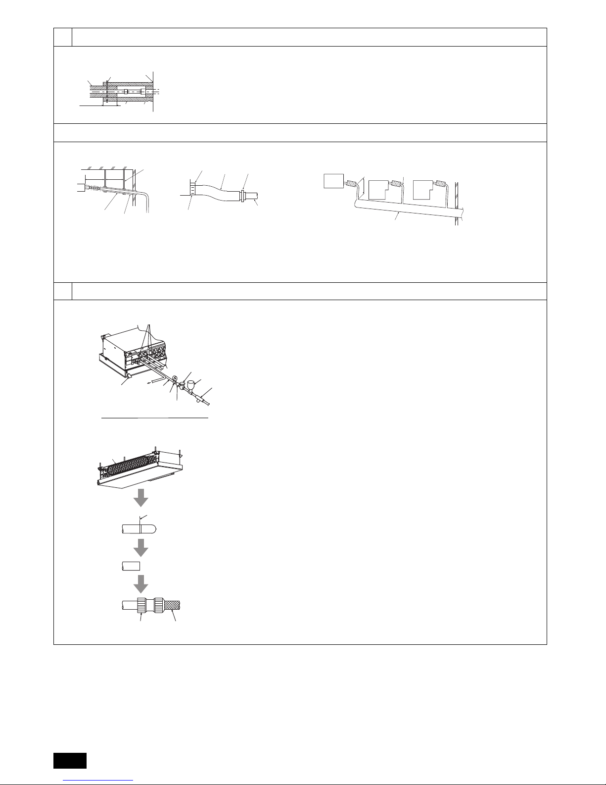
1. Drain piping work
• Ensure that the drain piping is downward (sloped gradient of more than 1/100) to
the outdoor (discharge) side. If it is impossible to take any downward pitch, use
an optionally available drain-up mechanism to obtain a downward pitch of more
than 1/100.
• Ensure that any cross-wise drain piping is less than 20 m. If the drain piping is
long, support it with metal brackets to prevent it from bending, warping, or vibrating.
• Connect the supplied drain hose to the discharge port on the unit body. Use hard
vinyl chloride pipes VP-25 (ø32) for drain piping (2). Tighten the supplied drain
hose onto the discharge port using the supplied hose band. (For this, do not use
any adhesive because the drain hose will need to be removed for servicing at a
later date.)
• Do not use any odor trap around the discharge port.
[Fig. 4.4.1] (P.4)
• As shown in 3, install a collecting pipe about 10 cm below the drain ports and give
it a downward pitch of more than 1/100. This collecting pipe should be of VP-30.
• Set the end of drain piping in a place without any risk of odor generation.
• Do not put the end of drain piping into any drain where ionic gases are generated.
• Drain piping may be installed in any direction. However, please be sure to
observe the above instructions.
[Fig. 4.4.2] (P.4)
2. Discharge test
After completing drain piping work, open the HBC controller panel, and test drain discharge using a small amount of water. Also, check to see that there is no water leakage from the connections.
3. Insulating drain pipes
Provide sufficient insulation to the drain pipes just as for refrigerant pipes.
Caution:
Be sure to provide drain piping with heat insulation in order to prevent excess
condensation. Without drain piping, water may leak from the unit causing
damage to your property.
A Main-HBC controller
B Twinning pipe (field supply)
C Slope of the twinning pipe is at an angle within ±15° to the ground
A Cut here B Remove brazed cap
A Locally procured insulating material for pipes
B Bind here using band or tape. C Do not leave any opening.
D Lap margin: more than 40 mm E Insulating material (field supply)
F Unit side insulating material
Outdoor unit High-pressure pipe 10 mm or more
-HBC controller Low-pressure pipe 20 mm or more
Temperature Resistance 100°C min.
A: 25 cm B: 1.5 – 2 m
A Downward gradient of more than 1/100
B Insulating material C Supporting bracket
D Drain discharge port E Drain hose (200 mm long, accessory)
F Cable tie (accessory) G Hose band (accessory)
A Main-HBC controller/Sub-HBC controller
B Indoor unit C Collecting pipe
D Please ensure this length is at least 100 mm.
11
GB
5. Connecting water pipework
Please observe the following precautions during installation.
5.1. Important notes on water pipework
installation
• The design pressure of the HBC water system is 0.6MPa.
• Use water pipe-work with a design pressure of at least 1.0MPa.
• When performing a water leak check, please do not allow the water pressure to
go above 0.3MPa.
• Perform a pressure test on the field-installed water pipes at a pressure equal to
1.5 times the design pressure. Before performing a pressure test, isolate the
pipes from HBC and indoor units.
• Please connect the water pipework of each indoor unit to the connect port on the
HBC. Failure to do so will result in incorrect running.
• Please list the indoor units on the naming plate in the HBC unit with addresses
and end connection numbers.
• Use the reverse-return method to insure proper pipe resistance to each unit.
• Provide some joints and valves around inlet/outlet of each unit for easy mainte-
nance, checkup, and replacement.
• Install a suitable air vent on the water pipe. After flowing water through the pipe,
vent any excess air.
• Secure the pipes with metal fitting, positioning them in locations to protect pipes
against breakage and bending.
• Do not confuse the water intake and outlet piping especially when connecting the
HBC controller and the Sub-HBC controller.
(Error code 5102 will appear on the remote controller if a test run is performed
with the pipe-work installed incorrectly (inlet connected to outlet and vice versa).)
• This unit doesn’t include a heater to prevent freezing within tubes. If the water
flow is stopped on low ambient, drain the water out.
• The unused knockout holes should be closed and the refrigerant pipes, water pipes,
power source and transmission wires access holes should be filled with putty.
• Install water pipe so that the water flow rate will be maintained.
• Wrap sealing tape as follows.
1 Wrap the joint with sealing tape following the direction of the threads (clock-
wise), do not wrap the tape over the edge.
2 Overlap the sealing tape by two-thirds to three-fourths of its width on each
turn. Press the tape with your fingers so that it is tight against each thread.
3 Do not wrap the 1.5th through 2nd farthest threads away from the pipe end.
• Hold the pipe on the unit side in place with a spanner when installing the pipes or
strainer. Tighten screws to a torque of 40 N·m.
• If there is a risk of freezing, carry out a procedure to prevent it.
• When connecting heat source unit water piping and on site water piping, apply
liquid sealing material for water piping over the sealing tape before connection.
• Please use copper or plastic pipes for the water circuit. Do not use steel or stain-
less steel pipework. Furthermore, when using copper pipe-work, use a non-oxidative brazing method. Oxidation of the pipe-work will reduce the pump life.
• Add water pressure gauge to see if the water pressure in HBC is correct or not.
• Be sure to braze the water pipes after covering a wet cloth to the insulation
pipes of the units in order to prevent them from burning and shrinking by
heat. (There are some plastic parts in HBC.)
Example of HBC controller installation
[Fig. 5.1.1] (P.4)
[Fig. 5.1.2] (P.4)
[Fig. 5.1.3] (P.5)
Note: Remove burr after cutting the piping to prevent entering the pipe con-
nection.
Check that there is no crack at the edge of the piping.
5.2. Water pipe insulation
1. Connect the water pipes of each indoor unit to the same (correct) end connection
numbers as indicated on the indoor unit connection section of each HBC controller.
If connected to wrong end connection numbers, there will be no normal operation.
2. List indoor unit model names in the name plate on the HBC controller control box
(for identification purposes), and HBC controller end connection numbers and
address numbers in the name plate on the indoor unit side.
In case of using cover caps for unused end connections, please use dezincification resistant brass (DZR) (field supply). Not using the rubber end caps will lead
to water leakage.
3. Be sure to add insulation work to water piping by covering water pipework separately with enough thickness heat-resistant polyethylene, so that no gap is
observed in the joint between indoor unit and insulating material, and insulating
materials themselves. When insulation work is insufficient, there is a possibility of
condensation, etc. Pay special attention to insulation work in the ceiling plenum.
[Fig. 5.2.1] (P.5)
• Insulation materials for the pipes to be added on site must meet the following
specifications:
• This specification is based on copper for water piping. When using plastic pipework, choose a thickness based on the plastic pipe performance.
• Installation of pipes in a high-temperature high-humidity environment, such as
the top floor of a building, may require the use of insulation materials thicker than
the ones specified in the chart above.
• When certain specifications presented by the client must be met, ensure that
they also meet the specifications on the chart above.
4. Expansion vessel
• Install an expansion vessel to accommodate expanded water.
• Please install expansion vessel at same height level of HBC.
Expansion vessel selection criteria:
• The water containment volume of the HBC and the indoor unit.
• The maximum water temperature is 60°C.
• The minimum water temperature is 5°C.
• The circuit protection valve set pressure is 370-490kPa.
• The circulation pump head pressure is 0.24MPa.
• The design pressure of the expansion vessel is the charged water pressure
(the reading of the pressure gauge).
• Tank volume of expansion vessel is as follows:
Tan k volu me = ε × G/(1 - (Psupply + 0.1)/0.29) × 1.2
ε = The expansion coefficient of water
(= 0.0171)
* Please choose ε for using antifreeze solution on the type and temperature range
used.
ε = Max density/Min density - 1
G [L] = (HBC [L] + Indoor unit [L] + Pipe [L]) × 1.1
Psupply: Water supply pressure [MPa]
5. Leakproof the water pipework, valves and drain pipework. Leakproof all the way
to, and include pipe ends so that condensation cannot enter the insulated pipework.
6. Apply caulking around the ends of the insulation to prevent condensation getting
between the pipework and insulation.
7. Add a drain valve so that the unit and pipework can be drained.
8. Ensure there are no gaps in the pipework insulation. Insulate the pipework right
up to the unit.
9. Ensure that the gradient of the drain pan pipework is such that discharge can
only blow out.
10. HBC water pipe connection sizes and pipe sizes.
[Fig. 5.2.2] (P.5)
* For other indoor units, refer to the indoor unit installation manual.
A Expansion vessel (field supply) B Shutoff valve (field supply)
C Strainer (field supply) D Pressure reducing valve (field supply)
E Water inlet F Refrigerant pipes
G Drain pipe H Pressure gauge (field supply)
I Check valve (field supply)
A Indoor unit connection B Cutting point
C Cut the piping at the cutting point D Field pipe connection (field supply)
E Field pipe F Pipe connection (field supply)
A HBC controller B Sub-HBC controller
C To Sub-HBC controller (Hot water) D From Sub-HBC controller (Hot water)
E To Sub-HBC controller (Cold water) F From Sub-HBC controller (Cold water)
A Locally procured insulating material for pipes
B Bind here using band or tape. C Do not leave any opening.
D Lap margin: more than 40 mm E Insulating material (field supply)
F Unit side insulating material
HBC controller
20 mm or more
-indoor unit
HBC controller
20 mm or more
-Sub-HBC controller
Indoor unit
Connection size Pipe size
Water inlet Water outlet Water out Water return
PEFY-WP·VMA
Rc 3/4
screw
Rc 3/4
screw
I.D. 20 mm I.D. 20 mm
A To o ut do or uni t
B End connection (brazing)
C Main-HBC controller
D Sub-HBC controller
E Indoor unit
F Twinning pipe (field supply)
(Unit: L)
Unit model Water volume
HBC Controller 10
PEFY-WP20VMA
0.7
PEFY-WP25VMA
1
PEFY-WP32VMA
PEFY-WP40VMA
1.8
PEFY-WP50VMA
* For other indoor units, refer to the installation manual for
each.
12
GB
Note:
*1. Connection of multiple indoor units with one connection (or joint pipe)
• Total capacity of connectable indoor units: Less than 80
• Number of connectable indoor units: Maximum 3 Sets
• Selection of water piping
Select the size according to the total capacity of indoor units to be installed down-
stream.
• Please group units that operate on 1 branch.
• When multiple indoor units are connected to a single port, install a pressure control valve in the pipe to equalize the pressure of all indoor units.
11. Please refer to the [Fig. 5.2.3] when connecting the water supply.
[Fig. 5.2.3] (P.5)
12. Use formula 0.1 [MPa] < 0.01 + 0.01 x A < 0.16 [MPa] for the supply pressure
range to be used.
(A: Head pressure (m) between the HBC and the highest indoor unit)
If the supply pressure is greater than 0.16 MPa, use a pressure reducing valve to
keep the pressure within the range.
If the head pressure is unknown, set it to 0.16 MPa.
13. Before performing a pressure test on the pipes in the water circuit, be sure to
install a shutoff valve on the inlet/outlet water pipes of the indoor units. Also,
install a strainer on the field-installed water pipes for easy operation and maintenance.
14. Apply insulation to the indoor unit pipework, strainer, shutoff valve, and pressure
reducing valve.
15. Please do not use a corrosion inhibitor in the water system.
16. When installing the HBC unit in an environment which may drop below 0°C,
please add antifreeze solution (Propylene Glycol only) to the circulating
water according to the local regulations.
5.3. Water treatment and quality control
To preserve water quality, use the closed type of water circuit. When the circulating
water quality is poor, the water heat exchanger can develop scale, leading to a
reduction in heat-exchange power and possible corrosion. Pay careful attention to
water processing and water quality control when installing the water circulation system.
• Removing of foreign objects or impurities within the pipes.
During installation, make sure that foreign objects, such as welding fragments,
sealant particles, or rust, do not enter the pipes.
• Water Quality Processing
2 Water quality standard
6. Electrical work
Consult all related regulations and power companies beforehand.
Warning:
Electrical work should be handled by qualified electrical engineers in accordance with all related regulations and attached instruction manuals. Special circuits should also be used. If there is a lack of power capacity or a deficiency in
electrical work, it may cause a risk of electric shock or fire.
Connect all wires securely.
• Fix power source wiring to control box by using buffer bushing for tensile force
(PG connection or the like).
[Fig. 6.0.1] (P.5)
Never connect the power cable to the terminal board for control cables.
(Otherwise it may be broken.)
Be sure to wire between the control wire terminal boards for indoor unit,
outdoor unit and HBC/Sub-HBC controller.
Use non-polarized 2-wire as transmission cables.
Use 2-core shielding cables (CVVS, CPEVS) of more than 1.25 mm
2
in diameter as
transmission cables.
The switch capacity of the main power to HBC/Sub-HBC controllers and the wire size
are as follows:
• For other detailed information, refer to the outdoor unit installation manual.
• Power supply cords of appliances shall not be lighter than design 245 IEC 53 or
227 IEC 53.
• A switch with at least 3 mm contact separation in each pole shall be provided by
the Air conditioner installation.
Caution:
Do not use anything other than the correct capacity fuse and breaker. Using
fuse, conductor or copper wire with too large capacity may cause a risk of malfunction or fire.
Ensure that the outdoor units are put to the ground. Do not connect the earth
cable to any gas pipe, water pipe, lightening rod or telephone earth cable. Incomplete grounding may cause a risk of electric shock.
7. Setting addresses and operating units
The address switch of each HBC/Sub-HBC controller is set to “000” when shipped
from the factory.
• Set the address switch to an address that equals the lowest address of the indoor
units that are connected to the HBC/Sub-HBC controller plus 50.
Assign the HBC controller address that equals the lowest address of the
indoor units that are connected to the HBC/Sub-HBC controller plus 50.
However, if the address overlaps any other units’ addresses, assign the
address that equals the next lowest address plus 50.
• Please refer to the outdoor unit installation manual.
G Up to three units for 1 branch hole; total capacity: below 80 (but in same mode, cool-
ing/heating)
H Shutoff valve (field supply)
I Pressure control valve (field supply)
J Auto air vent valve (Highest point on the water pipe) (field supply)
K Water pipework is screw connections
A HBC controller
B Water pipe
C Pressure gauge (field supply)
D Check valve (field supply)
E Shutoff valve (field supply)
F Pressure reducing valve (field supply)
G Strainer (field supply)
1 Depending on the quality of the cold-temperature water used in the aircondi-
tioner, the copper piping of the heat exchanger may corrode.
Regular water quality processing is recommended.
If a water supply tank is installed, keep air contact to a minimum, and keep
the level of dissolved oxygen in the water no higher than 1mg/ℓ.
Items
Low to mid-range
temperature water system
Tendency
Recirculating
water
[20<T<60°C]
[68<T<140°F]
Make-up
water
Corrosive
Scale-
forming
pH (25°C) [77°F]
7.0 ~ 8.0 7.0 ~ 8.0
Electric conductivity (mS/m) (25°C) [77°F]
30 or less
[300 or less]
30 or less
[300 or less]
(µ s/cm) (25°C) [77°F]
Chloride ion (mg Cl-/ℓ)
50 or less 50 or less
Sulfate ion (mg SO42-/ℓ)
50 or less 50 or less
Acid consumption (pH4.8)
50 or less 50 or less
(mg CaCO3/ℓ)
Total hardness (mg CaCO
3
/ℓ)
70 or less 70 or less
Calcium hardness (mg CaCO3/ℓ)
50 or less 50 or less
Ionic silica (mg SiO2/ℓ)
30 or less 30 or less
Iron (mg Fe/ℓ)
1.0 or less 0.3 or less
Copper (mg Cu/ℓ)
1.0 or less 0.1 or less
Sulfide ion
(mg S
2-
/ℓ)
not to be
detected
not to be
detected
Ammonium ion (mg NH
4
+
/ℓ)
0.3 or less 0.1 or less
Residual chlorine (mg Cl/ℓ)
0.25 or less
0.3 or less
Free carbon dioxide (mg CO2/ℓ)
0.4 or less 4.0 or less
Ryzner stability index
6.0 ~ 7.0 –
Reference : Guideline of Water Quality for Refrigeration and Air Conditioning
Equipment. (JRA GL02E-1994)
3 Consult with a specialist about water quality control methods and calculations
before using anti-corrosive solutions.
Standard items
Reference items
A Control box B Power source wiring
C ø21 hole (closed rubber bushing) D Transmission wiring
E Clip cables here
Switch (A)
Molded case
circuit breaker
Earth leakage
breaker
Wire size
Capacity Fuse
16 16 20 A
20 A 30 mA
0.1 s or less
1.5 mm
2

13
GB
8. Test run
Before commencing a test run please check the following:
After installing, piping and wiring the indoor units and HBC controllers,
check to see again that there is no refrigerant leakage, water leakage, the
indoor unit inlet and outlet piped backwards, and no slack on power and
control cables.
(Error code 5102 will appear on the remote controller if a test run is performed with the pipe-work installed incorrectly (inlet connected to outlet
and vice versa).)
Use a 500 V tester to check that there is an insulation resistance of more
than 1.0 MΩ between the power terminal block and the ground. If it is less
than 1.0 MΩ, do not operate the unit.
• When water has been supplied to the water pipework, purge the system of air.
The details of air purging can be found separately in the water circuit maintenance manual.
Caution:
• Never measure the insulation resistance of the terminal block for any control cables.
• Incomplete purging of the air in the system, closing of the valves upstream
or down stream of the pump etc. may cause the pump to operate with no
water flow and thus lead to pump failure.
• Ensure that the power is off when replacing a pump. Do not remove or
attach the pump connector with the power on. Otherwise pump will break.
After turning off the power, wait 10 minutes before commencing work.
14
GB
RATED INPUT (Cooling)
RATED CURRENT(Cooling)
RATED INPUT (Heating)
RATED CURRENT(Heating)
SERVICE REF.
MODEL
HBC CONTROLLER
UNIT RATING~ V
FREQUENCY Hz
220
230 240
50/60
50/60 50/60
ALLOWABLE PRESSURE(Ps)
4.15MPa
REFRIGERANT R410A
MAXIMUM WATER PRESSURE
0.6MPa
IP20
WEIGHT
SERIAL No.
MANUFACTURER: MITSUBISHI ELECTRIC CORPORATION
MADE IN JAPAN
5-66,TEBIRA,6-CHOME,WAKAYAMA CITY,
IP CODE
YEAR OF MANUFACTURE
AIR-CONDITIONING & REFRIGERATION
SYSTEMS WORKS
JAPAN
kW
A
kW
A
15
D
Inhalt
1. Sicherheitsvorkehrungen .................................................................................15
1.1. Vor Beginn der Installations- und Elektroarbeiten ..........................15
1.2. Vorkehrungen für Geräte, die R410A- Kältemittel verwenden .......16
1.3. Vor der Installation .........................................................................16
1.4. Vor Beginn der Installations- (Standortwechsel) und
Elektroarbeiten ...............................................................................16
1.5. Vor dem Start des Testbetriebs......................................................17
2. Wahl eines Aufstellortes ..................................................................................17
2.1. Produktinformationen .....................................................................17
2.2. Aufstellort .......................................................................................17
2.3. Freiraum für Installation und Bedienung ........................................17
2.4. Überprüfung des Aufstellortes........................................................17
3. Installation der HBC-Steuerung .......................................................................18
3.1. Überprüfung der mit der HBC-Steuerung gelieferten Teile ............18
3.2. Installation der HBC-Steuerungen..................................................18
4. Anschluß der Kältemittel- und Abwasserrohrleitungen....................................18
4.1. Anschluß der Kältemittelrohrleitungen ...........................................18
4.2. Arbeiten an der Kältemittelrohrleitung ............................................19
4.3. Isolierte Rohre ................................................................................19
4.4. Arbeiten an der Auslaufrohrleitung.................................................19
5. Anschließen der Wasserrohre .........................................................................20
5.1. Wichtige Hinweise zur Installation der Wasserrohre ......................20
5.2. Isolierung des Wasserrohrs............................................................20
5.3. Wasserbehandlung und Kontrolle der Wasserqualität ...................21
6. Elektroarbeiten.................................................................................................21
7. Einstellung der Adressen und Betrieb der Anlage ...........................................22
8. Testlauf ............................................................................................................22
1. Sicherheitsvorkehrungen
1.1. Vor Beginn der Installations- und Elektroarbeiten
In diesem Text verwendete Symbole
Achtung:
Beschreibt Vorkehrungen, die getroffen werden sollten, um einer Verletzungsoder Lebensgefahr des Anwenders vorzubeugen.
Vorsicht:
Beschreibt Vorkehrungen, die getroffen werden sollten, um einer Beschädigung
des Geräts vorzubeugen.
In den Illustrationen verwendete Symbole
ACHTUNG HOCHSPANNUNG:
• Die Steuerung enthält unter Hochspannung stehende Teile.
• Achten Sie darauf, dass die Frontverkleidung der Steuerung beim Öffnen
oder Schließen nicht mit internen Komponenten in Kontakt kommt.
• Schalten Sie vor der Inspektion des Inneren der Steuerung die Stromver-
sorgung aus, lassen Sie das Gerät mindestens 10 Minuten ausgeschaltet.
Achtung:
• Beauftragen Sie den Händler oder eine autorisierte Fachkraft mit der Instal-
lation des Klimageräts.
- Eine unsachgemäße Installation durch den Anwender kann in Wasserleckage,
Stromschlag oder Feuer resultieren.
• Installieren Sie das Gerät an einem Ort mit einer für sein Gewicht ausreichenden Tragkraft.
- Andernfalls könnte das Gerät herunterfallen und Verletzungen oder Geräte-
schäden verursachen.
• Verwenden Sie zur Verkabelung die angegebenen Kabel. Schließen Sie sie
sicher an, so dass externe auf das Kabel aufgebrachte Kräfte nicht auf die
Anschlüsse übertragen werden.
- Bei einem inkorrekten Anschluss oder Befestigen kann Hitze entstehen und ein
Brand verursacht werden.
• Treffen Sie Vorkehrungen zum Schutz vor starkem Wind und Erdbeben und
installieren Sie das Gerät am angegebenen Ort.
- Eine unsachgemäße Installation könnte im Herunterfallen des Geräts und in
Verletzungen oder Geräteschäden resultieren.
• Verwenden Sie ausschließlich von Mitsubishi Electric spezifiziertes Zubehör.
- Beauftragen Sie eine autorisierte Fachkraft mit der Installation des Zubehörs.
Eine unsachgemäße Installation durch den Anwender kann in Wasserlekkage,
Stromschlag oder Feuer resultieren.
• Versuchen Sie nie, das Gerät zu reparieren. Wenden Sie sich zur Reparatur
des Klimageräts stets an den Händler.
- Eine unsachgemäße Reparatur des Geräts kann in Wasserleckage, Strom-
schlag oder Feuer resultieren.
• Falls das Stromversorgungskabel beschädigt ist, muss es zur Vermeidung
von Gefahren durch den Hersteller, dessen Serviceagentur oder ähnlich
qualifiziert Personen ausgetauscht werden.
• Lüften Sie den Raum, falls während der Installationsarbeiten Kältegas austritt.
- Wenn das Kältegas mit einer offenen Flamme in Kontakt kommt, werden giftige
Gase freigesetzt.
• Installieren Sie das Klimagerät gemäß dieses Installationshandbuchs.
- Eine unsachgemäße Installation des Geräts kann in Wasserleckage, Strom-
schlag oder Feuer resultieren.
• Verändern und verstellen Sie Sicherheitseinrichtungen nicht.
- Ein Überbrücken der Druck- oder Temperaturschalter, um einen Betrieb zu
erzwingen, kann zu Beschädigung, Brand, Explosionen, etc. führen.
- Verändern Sie nicht die eingestellten Werte, da dies zu Beschädigung, Brand,
Explosionen, etc. führen kann.
- Die Verwendung von Produkten, die nicht von dieser Firma angegeben wur-
den, kann zu Beschädigung, Brand, Explosionen, etc. führen.
• Spritzen Sie kein Wasser auf die elektrischen Teile.
- Dies kann zu Kurzschluss, Brand, Rauchentwicklung, elektrischem Schlag,
Geräteversagen, etc. führen.
• Versiegeln Sie nicht Kältemittelkreisläufe, deren Systeme noch nicht vollständig mit Öl oder Kältemittel versorgt wurden.
- Dies kann zu Explosionen führen.
• Berühren Sie keine elektrischen Komponenten während oder unmittelbar
nach dem Betrieb.
- Dies kann zu Verbrennungen führen.
• Verschließen Sie Steuer- und Klemmenkästen mit Abdeckungen.
- Andernfalls kann es zu elektrischem Schlag durch Eindringen von Staub oder
Wasser, sowie Rauch, Brand, etc. kommen.
• Betreiben Sie das Gerät nicht mit abgenommenen Schutzabdeckungen
oder Panelen.
- Dies kann zu Verletzungen durch rotierende Teile, elektrischem Schlag durch
Hochspannung oder zu Verbrennungen durch hohe Temperaturen führen.
• Setzen Sie sich nicht auf das Gerät und stellen Sie keine Objekte darauf.
- Das Gerät könnte umfallen und dies zu Verletzungen führen.
• Verwenden Sie die geeignete Fangvorrichtung.
- Es könnte zu elektrischem Schlag durch Hochspannung kommen.
- Heiße Teile könnten Verbrennungen verursachen.
• Stellen Sie das Kältemittel im Gerät wieder her.
- Verwenden Sie das Kältemittel wieder oder lassen Sie es durch einen Spezia-
listen entsorgen.
- Ein Freiwerden des Kältemittels kann die Umwelt schädigen.
• Reinigen Sie die Rohrleitungen von Gas- und Ölresten.
- Andernfalls kann es zu Stichflammen und Verbrennungen durch heiße Rohrlei-
tungen kommen.
• Vakuumtrocknen Sie die Kältemittel-Rohrleitungen. Ersetzen Sie das Kältemittel nicht durch eines, das nicht spezifiziert ist.
- Dies könnte zu Explosionen, Brand, etc. führen.
• Berühren Sie nicht die Enden der Rohrleitungen am Standort.
- Dies könnte die Rohrleitungen beschädigen und in der Folge zu Kältemittel-
Leckagen und Sauerstoffmangel führen.
• Alle Elektroarbeiten müssen von einem lizenzierten Elektriker gemäß dem
“Technischen Standard für Elektroanlagen” und den “Verkabelungsvorschriften für Innenräume” sowie den in diesem Handbuch gegebenen
Anleitungen ausgeführt werden. Des Weiteren ist eine geeignete Stromversorgung zu verwenden.
- Eine unzureichende Kapazität der Stromversorgung oder inkorrekt ausgeführte
Elektroarbeiten können in Stromschlag oder Feuer resultieren.
• Installieren Sie die Abdeckung des Schaltkastens sicher.
- Wenn die Abdeckung der Elektroanschlüsse nicht sachgemäß angebracht
wurde, kann Staub oder Wasser in die Außenanlage eindringen und Brand
oder Stromschlag verursachen.
Lesen Sie vor dem Installieren des Geräts unbedingt alle im
Abschnitt “Sicherheitsvorkehrungen” beschriebene Hinweise.
Der Abschnitt “Sicherheitsvorkehrungen” verweist auf sehr
wichtige Sicherheitsaspekte. Achten Sie auf ihre Befolgung.
: Verweist auf einen Vorgang, der vermieden werden muss.
: Verweist auf wichtige Anleitungen, die befolgt werden müssen.
: Verweist auf ein Teil, das geerdet sein muss.
: Stromschlaggefahr. (Dieses Symbol ist am Etikett des Hauptgeräts ange-
bracht.) <Farbe: Gelb>
Achtung:
Lesen Sie die am Hauptgerät angebrachten Etiketten sorgfältig.

16
D
• Wenn das Klimagerät installiert oder an einen anderen Ort transportiert
wird, darf es mit keinem anderen als dem am Gerät angegebenen Kältemittel gefüllt werden.
- Falls ein anderes Kältemittel oder Luft mit dem Originalkältemittel gemischt
wird, kann dies in einer Funktionsstörung des Kältemittelkreislaufs oder einer
Beschädigung des Geräts resultieren.
•
Bei der Installation des Klimageräts in einem kleinen Raum müssen Vorkehrungen getroffen werden, um ein Überschreiten der Sicherheitsgrenze der
Kältemittelkonzentration im Fall einer Leckage von Kältemittel zu verhindern.
- Holen Sie den Rat des Händlers bezüglich angemessener Maßnahmen zur
Verhinderung der Überschreitung dieser Sicherheitsgrenze ein. Bei einer Lekkage von Kältemittel und einem Überschreiten der Sicherheitsgrenze besteht
im Raum Gefahr in Folge von Sauerstoffmangel.
• Holen Sie beim Transportieren oder der Neuinstallation des Klimageräts
den Rat des Händlers oder einer autorisierten Fachkraft ein.
- Eine unsachgemäße Installation des Klimageräts kann in Wasserleckage,
Stromschlag oder Feuer resultieren.
• Überzeugen Sie sich nach Abschluss der Installationsarbeiten, dass kein
Kältegas austritt.
- Falls Kältegas austritt und mit einem Heizlüfter, Herd, Ofen oder einer anderen
Wärmequelle in Kontakt kommt, können giftige Gase freigesetzt werden.
• Rekonstruieren oder verändern Sie die Schutzvorrichtungen nicht.
- Falls der Druckschalter, Thermoschalter oder eine andere Schutzvorrichtung
kurzgeschlossen oder gewaltsam bedient wird oder andere als von Mitsubishi
Electric angegebene Teile verwendet werden, besteht Brand- oder Explosionsgefahr.
• Holen Sie zur Entsorgung dieses Produkts den Rat Ihres Händlers ein.
• Der Installateur und Systemspezialist gewährleistet die Leckagesicherheit
im Einklang mit den örtlich geltenden Vorschriften bzw. Normen.
- Falls keine örtlich geltenden Vorschriften verfügbar sind, treffen die Maßanga-
ben für die Kabellitzen und die Kapazitäten des Hauptstromschalters zu.
• Tragen Sie insbesondere dem Installationsort wie zum Beispiel einem Keller usw. - wo sich Kältegas ansammeln kann - Rechnung, da Kältemittel
schwerer als Luft ist.
•
Dieses Gerät ist nicht für die Verwendung durch Personen (einschließlich Kinder)
mit verminderten physischen, Wahrnehmungs-oder geistigen Fähigkeiten oder
mit mangelnder Erfahrung oder mangelnden Kenntnissen vorgesehen, es sei
denn, sie wurden von einer für ihre Sicherheit verantwortliche Person in der Verwendung des Geräts überwacht bzw. in diese eingewiesen.
• Kinder sollten beaufsichtigt werden, um zu gewährleisten, dass sie nicht
mit dem Gerät spielen.
1.2. Vorkehrungen für Geräte, die R410A-
Kältemittel verwenden
Vorsicht:
• Verwenden Sie keine bereits vorhandenen Kältemittelleitungen.
- In den vorhandenen Leitungen verbliebenes altes Kältemittel und Kühlöl kann
einen hohen Chloranteil aufweisen und einen Güteverlust des Kühlöls des
neuen Geräts verursachen.
- R410A ist ein Hochdruckkältemittel, das im Bersten der vorhandenen Leitun-
gen resultieren kann.
• Verwenden Sie Kältemittelleitungen aus deoxidiertem Phosphorkupfer
sowie nahtlose Kupferlegierungsleitungen und -rohre. Vergewissern Sie
sich des Weiteren, dass die Innen- und Außenfl ächen der Leitungen frei
von gefährlichen Rückständen wie Schwefel, Oxiden, Staub/Schmutz, Spänen, Ölen, Feuchtigkeit und jeglichen anderen Kontaminierungen sind.
- Kontaminierungsstoffe im Inneren der Kältemittelleitungen können einen Güte-
verlust des Kältemittelöls bewirken.
• Lagern Sie die bei der Installation zu verwendenden Rohrleitungen in
einem Innenraum und halten Sie beide Rohrenden bis kurz vor dem Hartlöten verschlossen. (Bewahren Sie Rohrbögen und andere Verbindungselemente in einem Kunststoffbeutel auf.)
- Das Eindringen von Staub, Schmutz oder Wasser in den Kältemittelkreislauf
kann im Güteverlust des Öls und im Ausfall des Kompressors resultieren.
• Tragen Sie etwas Esteröl, Ätheröl oder Alkylbenzol auf die Rohrmuffen auf.
(Innengerät)
- Das Eindringen einer größeren Menge von Mineralöl kann einen Güteverlust
des Kältemittelöls verursachen.
• Verwenden Sie fl üssiges Kältemittel zum Füllen des Systems.
- Wenn das System mit Kältegas gefüllt wird, ändert sich die Zusammensetzung
des Kältemittels im Zylinder und es kann zu einem Leistungsverlust kommen.
• Verwenden Sie kein anderes Kältemittel als R410A.
- Falls ein anderes Kältemittel (R22 usw.) mit R410A gemischt wird, kann das im
Kältemittel enthaltene Chlor einen Güteverlust des Kältemittelöls verursachen.
• Verwenden Sie eine Vakuumpumpe mit Rückschlagventil.
- Aus der Vakuumpumpe könnte Öl in den Kältemittelkreislauf zurückfl ießen
und einen Güteverlust des Kältemittelöls verursachen.
• Verwenden Sie keine der folgenden Hilfsmittel, die in Verbindung mit herkömmlichen Kältemitteln verwendet werden.
(Messverteiler, Füllschlauch, Gasleckagedetektor, Rückschlagventil, Kältemittelfüllständer, Kältemittelrückgewinnungsausrüstung)
- Das Mischen von herkömmlichem Kältemittel mit Kältemittelöl kann einen
Güteverlust des R410A-Kältemittels verursachen.
- Das Mischen von Wasser und R410A kann einen Güteverlust des Kältemittel-
öls verursachen.
- Da R410A vollkommen chlorfrei ist, sprechen für herkömmliche Kältemittel verwendete Gasleckagesensoren unter Umständen nicht an.
• Verwenden Sie keinen Füllzylinder.
- Die Verwendung eines Füllzylinders kann einen Güteverlust des Kältemittels
verursachen.
• Kein Antioxidations- oder Zusatzmittel für Leckentdeckung verwenden.
• Gehen Sie bei der Handhabung der Hilfsmittel besonders sorgfältig vor.
- Falls Staub, Schmutz oder Wasser in den Kältemittelkreislauf eindringt, kann
dies einen Güteverlust des Kältemittels verursachen.
1.3. Vor der Installation
Vorsicht:
• Installieren Sie das Gerät nicht an Orten, wo brennbares Gas austreten
kann.
-
Wenn Gas austritt und sich um das Gerät ansammelt, besteht Explosionsgefahr.
• Verwenden Sie das Klimagerät nicht in der Nähe von Lebensmitteln, Haustieren, Pfl anzen, Präzisionsinstrumenten oder Kunstgegenständen.
- Andernfalls könnte die Qualität der Lebensmittel usw. beeinträchtigt werden.
• Verwenden Sie das Klimagerät nicht in Sonderumgebungen.
- Öl, Dampf, schwefelhaltiger Rauch usw. können eine signifi kante Leistungs-
minderung des Klimageräts oder eine Beschädigung seiner Teile verursachen.
•
Bei der Installation des Geräts in einem Krankenhaus, einer Kommunikationszentrale oder ähnlichen Orten ist für eine ausreichende Schalldämmung
zu sorgen.
- Der Schalldruckpegel überschreitet nicht 70 dB(A). Der Betrieb der Anlage
kann aber gestört oder unterbrochen werden, wenn sie durch Aufnahmegeräte, private Stromerzeugungseinrichtungen, medizinische Hochfrequenzgeräte oder Rundfunkeinrichtungen beeinflusst wird. Demgegenüber kann sich
das Klimagerät selbst durch Störgeräusche auf solche Geräte oder Anlagen
auswirken und zum Beispiel die medizinische Behandlung oder Bildübertragung stören.
• Installieren Sie das Gerät nicht auf einer Struktur, die Leckage verursachen
könnte.
- Bei einer Raumfeuchtigkeit von mehr als 80 % oder einer blockierten Draina-
geleitung kann Kondensat aus dem Innengerät oder dem HBC-Controller auslaufen. Treffen Sie die erforderlichen Drainagevorkehrungen in Verbindung mit
der Außeneinheit.
1.4. Vor Beginn der Installations- (Standort-
wechsel) und Elektroarbeiten
Vorsicht:
• Erden Sie das Gerät.
- Schließen Sie das Erdungskabel nicht an Gas- oder Wasserleitungen, Blitzab-
leiter oder unterirdische Telefonleitungen an. Eine inkorrekte Erdung kann in
Stromschlag resultieren.
• Installieren Sie das Stromkabel so, dass es nicht unter Zugspannung steht.
- Zugkräfte können das Durchreißen des Kabels verursachen sowie in Wärme-
entwicklung und Brandgefahr resultieren.
• Installieren Sie bei Bedarf einen Leckageschutzschalter.
- Falls kein Leckageschutzschalter installiert wird, kann Stromschlaggefahr
bestehen.
• Verwenden Sie Stromkabel mit einer ausreichenden Stromübertragungskapazität und Nennleistung.
- Unterdimensionierte Kabel können Kriechstrom, Wärmeentwicklung und
Brandgefahr bewirken.
• Verwenden Sie nur einen Schutzschalter und eine Sicherung mit der angegebenen Kapazität.
- Ein Schutzschalter oder eine Sicherung mit einer höheren Kapazität oder
deren Ersatz durch einen einfachen Stahl- oder Kupferdraht kann in einem
generellen Geräteausfall oder Feuer resultieren.
• Reinigen Sie die Klimageräte nicht mit Wasser.
- Beim Reinigen der Geräte mit Wasser besteht Stromschlaggefahr.
• Achten Sie darauf, dass die Gerätehalterung nicht durch langfristige Verwendung beschädigt wird.
- Falls Beschädigungen nicht repariert werden, kann das Gerät herunterfallen
und Personen- oder Sachschäden verursachen.
•
Installieren Sie die Drainageleitung zur Gewährleistung einer ordnungsgemäßen Drainage entsprechend den Anleitungen in diesem Installationshandbuch.
Umhüllen Sie die Rohrleitungen zum Vermeiden von Kondensation mit Isoliermaterial.
- Eine inkorrekte Drainage kann in Wasserleckage und der Beschädigung von
Möbeln und anderen Gegenständen resultieren.
• Gehen Sie beim Transport des Produkts sehr sorgfältig vor.
- Das Produkt sollte nicht von nur einer Person getragen werden. Es hat ein
Gewicht von 20 kg.
- An bestimmten Produkten wird PP-Band zur Verpackung verwendet. Verwen-
den Sie PP-Band nicht zum Tragen und Transportieren des Geräts. Dies ist
gefährlich.
• Achten Sie auf eine sichere Entsorgung des Verpackungsmaterials.
- Verpackungsmaterial wie Nägel oder andere Metall- und Holzteile kann Stech-
wunden oder andere Verletzungen verursachen.
- Zerreißen Sie Kunststoffverpackungsbeutel und entsorgen Sie sie so, dass
Kinder nicht mit ihnen spielen können. Kinder, die mit nicht zerrissenen Kunststoffbeuteln spielen, sind einer Erstickungsgefahr ausgesetzt.
17
D
1.5. Vor dem Start des Testbetriebs
Vorsicht:
• Schalten Sie die Stromversorgung mindestens 12 Stunden vor Betriebsbeginn ein.
- Der Betriebsbeginn unmittelbar nach dem Einschalten des Hauptstromschal-
ters kann in der irreversiblen Beschädigung interner Komponenten resultieren.
Lassen Sie den Stromschalter während der Betriebssaison eingeschaltet. Vergewissern Sie sich von der korrekten Phasenanordnung der Stromversorgung
und der Spannung zwischen jeder Phase.
• Berühren Sie die Schalter nicht mit nassen Fingern.
- Das Berühren eines Schalters mit nassen Fingern kann in einem Stromschlag
resultieren.
• Berühren Sie die Kältemittelleitungen nicht während des Betriebs und
unmittelbar danach.
- Die Kältemittelleitungen können während des Betriebs oder unmittelbar
danach - je nach dem Zustand des durch die Kältemittelleitungen, den Kompressor und andere Komponenten des Kältemittelkreislaufs fl ießenden Kältemittels - heiß oder kalt sein. Das Berühren der Kältemittelleitungen kann
Verbrennungen oder Frostverletzungen Ihrer Hände verursachen.
• Betreiben Sie das Klimagerät nicht bei entfernten Abdeckungen und
Schutzvorrichtungen.
- Es besteht eine Verletzungsgefahr durch sich drehende, heiße oder unter
Hochspannung stehende Teile.
• Schalten Sie die Stromversorgung nicht unmittelbar nach dem Beenden
des Betriebs aus.
- Warten Sie vor dem Ausschalten der Stromversorgung stets mindestens 5
Minuten. Andernfalls besteht die Gefahr, dass Drainagewasser ausfl ießt oder
empfi ndliche Teile mechanisch beschädigt werden
2. Wahl eines Aufstellortes
2.1. Produktinformationen
• Dieses Gerät verwendet Kältemittel des Typs R410A.
• Nur die „WP“-Modelle der Innengeräte können angeschlossen werden.
• Rohrleitungen für Systeme, die R410A verwenden, können aufgrund des konstruktionsbedingten höheren Drucks bei Verwendung von R410A von denen für
Systeme, die herkömmliche Kältemittel verwenden, abweichen. Weitere Informationen sind im Datenbuch enthalten.
• Einige zur Installation von Systemen, die andere Kältemitteltypen einsetzen, verwendete Hilfsmittel und Geräte können nicht für Systeme verwendet werden, die
R410A einsetzen. Weitere Informationen sind im Datenbuch enthalten.
• Verwenden Sie keine vorhandenen Rohrleitungen, da diese Chlor enthalten, das
in herkömmlichen Kühlmaschinenölen und Kältemitteln Verwendung findet. Das
Chlor beeinträchtigt das im neuen System verwendete Kältemittelöl. Die vorhandenen Rohrleitungen dürfen auch deshalb nicht verwendet werden, weil der konstruktionsbedingte Druck in Systemen, die R410A verwenden, höher ist als in
Systemen, die andere Kältemittel verwenden, so dass die vorhandenen Rohrleitungen bersten könnten.
2.2. Aufstellort
• Stellen Sie das Gerät an einem vor Regen geschützten Ort auf. Der HBC-Controller ist für die Installation im Hausinneren konstruiert.
• Lassen Sie genügend Platz um das Gerät herum für Wartungen und Kundendienst.
• Stellen Sie das Gerät nicht so auf, dass die Beschränkung der Leitungslänge
überschritten wird.
• Setzen Sie das Gerät nicht der direkten Wärmestrahlung anderer Hitze erzeugenden Geräte aus.
• Anlage nicht an einem Ort, der Öldampf ausgesetzt ist oder neben einer
Maschine aufstellen, die Hochfrequenzen erzeugt, da sonst Brandgefahr besteht
oder Fehlfunktionen sowie Kondenswasser entstehen können. Andernfalls kann
es zu Brand, Fehlfunktionen oder Kondensation kommen.
• Je nach den Betriebsbedingungen kann die HBC-Einheit Geräusche durch Ventilaktivierung, Kältemittelfluss und Druckänderungen erzeugen, auch bei normalem Betrieb. Installieren Sie deshalb das Innengerät an Orten wie Decken von
Korridoren, Toiletten und Werkstätten.
• Installieren Sie das Innengerät und das HBC-Steuergerät bei Installation an
Orten mit niedrigem Hintergrundgeräusch, z.B. Hotelzimmern, mindestens 5 m
voneinander entfernt.Lassen Sie genug Abstand, damit die Wasser- und Kältemittelrohrleitungen sowie die Elektrokabel problemlos angeschlossen werden
können.
• Lassen Sie genug Abstand, damit die Wasser- und Kältemittelrohrleitungen
sowie die Elektrokabel problemlos angeschlossen werden können.
• Am Aufstellort dürfen brennbare Gase oder Schwefelgase weder erzeugt, zugeführt, angesammelt werden noch austreten.
• Sorgen Sie für ein Gefälle der Abflussrohrleitung von mindestens 1/100.
• Installieren Sie das Gerät vorschriftsmäßig auf einem soliden tragfähigen Untergrund.
1. Zum Aufhängen an der Decke [Fig. 2.2.1] (P.2)
• Sorgen Sie in der Decke für zwei Inspektionslöcher von 450 mm, wie in [Fig.
2.3.1] (P.2) dargestellt.
• Installieren Sie das Gerät an einem geeigneten Ort (in einer Flurdecke oder in
einem Badezimmer etc.), nicht in viel genutzten Räumlichkeiten. Installieren Sie
das Gerät am besten nicht mitten im Raum.
• Stellen Sie sicher, dass die Hängeschrauben über genügend Zugfestigkeit verfügen.
Achtung:
Stellen Sie sicher, dass der zur Installation vorgesehene Ort dem Gewicht des
Gerätes standhält.
Bei zu geringer Belastbarkeit kann die Anlage herunterfallen und Verletzungen
hervorrufen.
Vorsicht:
• Stellen Sie sicher, dass das Gerät waagerecht montiert wird.
Montieren Sie das HBC eben (max. 1° Neigung), so dass die Ablaufwanne
korrekt funktioniert.
• Montieren Sie das HBC an einem Platz, an dem die Temperatur immer über
0°C beträgt.
2.3. Freiraum für Installation und Bedienung
1. Beim Herunterhängen von der Decke
(Diese Ansi cht zeigt den geringst möglichen Freiraum für die Installation.)
[Fig. 2.3.1] (P.2)
2.4. Überprüfung des Aufstellortes
Vergewissern, daß die Steigungsdifferenz zwischen Innen- und Außenanlage und
die Länge der Kältemittelrohrleitung innerhalb nachstehender Grenzwerte liegen.
1. CMB-WP108V-GA1 + CMB-WP108V-GB1
(
CMB-WP1016V-GA1
) (
CMB-WP1016V-GB1
)
[Fig. 2.4.1] (P.2)
Hinweise:
*1 Innenanlagen, die sich einen Verteileranschluss teilen, können nicht zur
gleichen Zeit in unterschiedlichen Betriebsarten laufen.
<A> Ansicht von oben <B> Vorderansicht
A Inspektionsöffnung
B Auf der Rohrleitungsseite der Außenanlage
C Schaltkasten
D Auf der Rohrleitungsseite der Innenanlage
E Wassereinlass F Servicebereich
G Innenseite
*1
Abmessungen, bei denen der Rohrleitungsanschluß vor Ort vorgenommen werden kann
Modellbezeichnung A B
CMB-WP108V-GA1 1520 160
CMB-WP1016V-GA1 1800 300
CMB-WP108V-GB1 1520 160
CMB-WP1016V-GB1 1520 160
A Außenanlage B Haupt-HBC-Steuergerät
C Neben-HBC-Steuergerät D Innenanlage
E Weniger als H=50 m (wenn das Außengerät höher als HBC ist)
F
Weniger als H1=40 m (
wenn das Außengerät höher als HBC ist)
G Zwillingsrohr (vor Ort zu beschaffen)
H Weniger als 110 m I Weniger als 60 m
J Bis zu drei Anlagen je 1 Abzweigöffnung
Gesamtkapazität: weniger als 80 (aber gleich wie bei Kühl-/Heizbetrieb)
K Weniger als 15 m L Weniger als 15 m
(Einheit: m)
Position
Rohrleitungs-
abschnitt
Zulässiger Wert
Zwischen Außenanlage und HBC-Steuerung (Kältemittelrohrleitungen)
A
110 oder weniger
Wasserrohrleitungen zwischen Innenanlagen und HBC-Steuerung
f + g 60
oder weniger
Zwischen
Innen- und
Außenanlage
Oberhalb
Außenanlage
H 50
oder weniger
Unterhalb
Außenanlage
H1 40
oder weniger
Zwischen Innenanlagen und
HBC-Steuerung
h1 15
oder weniger
Zwischen Innenanlagen h2 15
oder weniger
Rohrlängen
Steigungsdifferenz
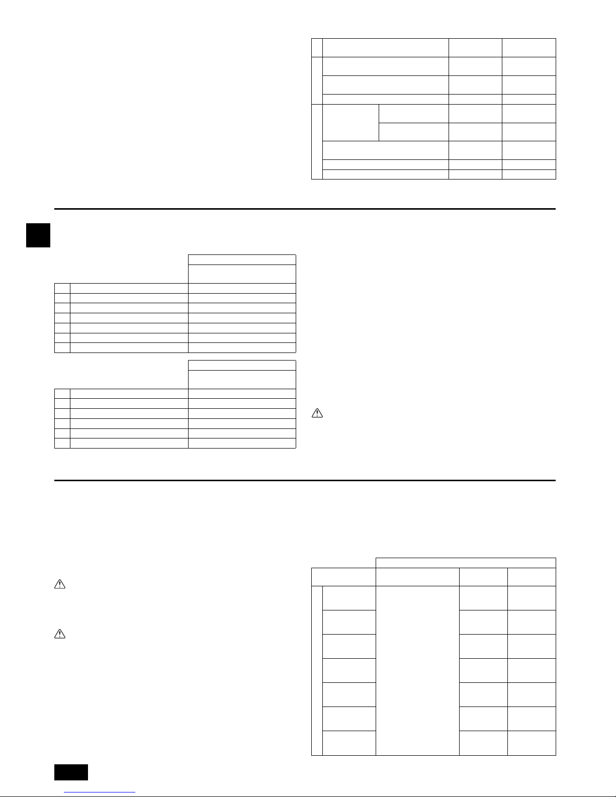
18
D
2. CMB-WP108V-GA1 + CMB-WP108V-GB1
(
CMB-WP1016V-GA1
) (
CMB-WP1016V-GB1
)
[Fig. 2.4.2] (P.2)
3. Installation der HBC-Steuerung
3.1. Überprüfung der mit der HBC-Steuerung
gelieferten Teile
Nachstehende Teile wurden mit jeder HBC-Steuerung geliefert.
3.2. Installation der HBC-Steuerungen
Anbringen der Aufhängungsbolzen
Nehmen Sie die Installation mit örtlich beschafften Hängebolzen (Gewindestange)
entsprechend dem in der Abbildung gzeigten Verfahren vor. Größe der Aufhängungsbolzen: ø10 (M10-Schraube).
Zum Aufhängen der Anlage diese mit einer Hebevorrichtung anheben und in die Aufhängungsbolzen einführen.
Aufhängelasche hat ein ovales Loch. Verwenden Sie eine Unterlegscheibe mit großem Durchmesser.
[Fig. 3.2.1] (P.3)
Stellen Sie sicher, dass die HBC-Steuerung waagerecht unter Zuhilfenahme
einer Wasserwaage installiert wird. Wird die Steuerung schräg installiert,
kann Drainagewasser austreten. Neigt sich die Steuerung muss ihre Position durch Lösen der Befestigungsmuttern an der Halterung angepasst
werden.
Montieren Sie das HBC eben (max. 1° Neigung), so dass die Ablaufwanne
korrekt funktioniert.
Vorsicht:
• Stellen Sie sicher, dass das Gerät waagerecht installiert wird.
Montieren Sie das HBC eben (max. 1° Neigung), so dass die Ablaufwanne
korrekt funktioniert.
4. Anschluß der Kältemittel- und Abwasserrohrleitungen
4.1. Anschluß der Kältemittelrohrleitungen
1. Darauf achten, daß im Bedarfsfall nichtoxidierende Hartlötverfahren angewendet
werden. Bei Nichtanwendung von nichtoxidierenden Hartlötverfahren können die
Rohrleitungen verstopfen.
Leiten Sie beim Hartlöten des Außengeräteanschlussports der HBC-Steuerung
Stickstoffgas in die Rohrleitung zwischen dem Außengerät und der HBC-Steuerung ein.
2. Nach dem Herstellen der Rohrverbindungen die Rohre abstützen, um sicherzustellen, daß die Last nicht an die Endverbindungen an der HBC-Steuerung angelegt wird.
Achtung:
Beim Installieren und Verlegen der Anlage kein anderes Kältemittel als das auf
der Anlage angegebene Kältemittel (R410A) einfüllen.
- Vermischung mit einem anderen Kältemittel, mit Luft etc. kann zu Fehlfunktionen
des Kältemittelkreislaufs und zu schweren Schäden an der Anlage führen.
Vorsicht:
• Kältemittelrohrleitungen aus Phosphor-deoxidiertem Kupfer und nahtlose
Rohrleitungen und Rohre aus Kupfer und Kupferlegierung verwenden.
Außerdem vergewissern, dass die Innen- und Außenflächen der Rohrleitungen sauber und frei von gefährlichem Kupfer, Oxyden, Staub/Schmutz,
Metallbearbeitungsrückständen, Ölen, Feuchtigkeit oder anderen Verunreinigungen sind.
- R410A ist ein Hochdruckkühlmittel und kann vorhandene Leitungen zum Plat-
zen bringen.
• Die zu verwendende Rohrleitung während der Installation in einem
geschlossenen Raum aufbewahren und beide Enden der Rohrleitung bis
unmittelbar vor dem Hartlöten abgedichtet lassen. (Krümmer und andere
Rohrverbinder in einem Kunststoffbeutel aufbewahren.)
- Wenn Staub, Schmutz oder Wasser in den Kältemittelkreislauf gelangt, kann
dies zu einer Qualitätsminderung des Öls und zu Kompressorstörungen führen.
- Das Eindringen einer größeren Menge von Mineralöl kann einen Güteverlust
des Kältemittelöls verursachen.
• Lassen Sie R410A nicht in die Atmosphäre entweichen.
• R410A ist ein fluoriertes Treibhausgas, das im Kyoto-Protokoll mit einem
Erderwärmungspotenzial (GWP) = 2090 aufgeführt wird.
1. Größe des Rohrleitungsanschlusses am Ende der HBC-Steuerung
[Fig. 4.1.2] (P.3)
A Außenanlage B Haupt-HBC-Steuergerät
C Neben-HBC-Steuergerät D Innenanlage
E Weniger als H=50 m (wenn die Außenanlage sich höher als die Innenanlage befindet)
F
Weniger als H1=40 m (wenn die Außenanlage sich tiefer als die Innenanlage befindet)
G Zwillingsrohr (vor Ort zu beschaffen)
H Weniger als 110 m I Weniger als 60 m
J Bis zu drei Anlagen je 1 Abzweigöffnung
Gesamtkapazität: weniger als 80 (aber gleich wie bei Kühl-/Heizbetrieb)
K Weniger als 15 m L Weniger als 15 m
M Weniger als 15 m
(Einheit: m)
Position
Rohrleitungs-
abschnitt
Zulässiger Wert
Zwischen Außenanlage und HBC-Steuerung (Kältemittelrohrleitungen)
A
110 oder weniger
Wasserrohrleitungen zwischen Innenanlagen und HBC-Steuerung
f + g 60
oder weniger
Zwischen HBC-Steuergeräten B 40
oder weniger
Zwischen
Innen- und
Außenanlage
Oberhalb
Außenanlage
H50
oder weniger
Unterhalb
Außenanlage
H1 40
oder weniger
Zwischen Innenanlagen und
HBC-Steuerung
h1 15
oder weniger
Zwischen Innenanlagen h2 15
oder weniger
Zwischen HBC-Steuergeräten h3 15
oder weniger
Rohrlängen
Steigungsdifferenz
Modellbezeichnung
CMB-WP108V-GA1
CMB-WP1016V-GA1
Position Menge
1 Abflussleitung 1
2 Binder 1
3 Schlauchschelle 1
4 Installationshandbuch 1
5 Luftabzug-Handbuch 1
6 Schraubenschlüssel 1
Modellbezeichnung
CMB-WP108V-GB1
CMB-WP1016V-GB1
Position Menge
1 Abflussleitung 1
2 Binder 1
3 Schlauchschelle 1
4 Installationshandbuch 1
5 Luftabzug-Handbuch 1
1 Aufhängungsverfahren
A: Mindestens.30 mm
A Aufhängungsbolzen mit ø10 (vor Ort zu beschaffen.)
B Unterlegscheibe (vor Ort zu beschaffen.)
HBC-CONTROLLER
Anlage Modell Modellbezeichnung
Niederdruck-
seite
Hochdruck-
seite
PURY-(E)P200
(HBC-CONTROLLER)
CMB-WP108V-GA1
CMB-WP1016V-GA1
*1
ø15,88
(Hartlötung)
ø19,05
(Hartlötung)
PURY-(E)P250
ø19,05
(Hartlötung)
ø22,2
(Hartlötung)
PURY-(E)P300
ø19,05
(Hartlötung)
ø22,2
(Hartlötung)
PURY-(E)P350
ø19,05
(Hartlötung)
ø28,58
(Hartlötung)
PURY-(E)P400
ø15,88 (Hartlötung)
für jede HBC
ø19,05 (Hartlötung)
für jede HBC
PURY-(E)P450
ø15,88 (Hartlötung)
für jede HBC
ø22,2 (Hartlötung)
für jede HBC
PURY-(E)P500
ø19,05 (Hartlötung)
für jede HBC
ø22,2 (Hartlötung)
für jede HBC
Außenseite
19
D
Hinweis:
• Darauf achten, daß nichtoxidierende Hartlötverfahren angewendet werden.
*1. Modell PURY-(E)P-400YLM oder höher erfordert den Anschluss von minde-
stens zwei Haupt-HBC-Steuergeräten in parallel.
4.2. Arbeiten an der Kältemittelrohrleitung
Nachdem die Kältemittelleitungen der Außenanlagen bei vollständig geschlossenen
Absperrventilen der Außenanlagen angeschlossen wurden, evakuieren Sie die
Außenanlagen über die Wartungsanschlüsse der Absperrventile.
Nach dem Ausführen der obigen Schritte die Absperrventile der Außenanlage öffnen. Dadurch wird der Kältekreis (zwischen Außenanlage und HBC-Steuerung) vollständig angeschlossen.
Beschreibungen über die Behandlung der Ventilspindeln finden sich auf jeder
Außenanlage.
Vorsichtsmaßregeln für HBC-Steuergerät-Kombinationen
Siehe [Fig. 4.2.1] zur Positionierung der Zwillingsleitungen.
[Fig. 4.2.1] (P.3)
Hinweise:
• Nach Rohrleitungsanschluß mit einem Lecksensor oder einer Seifenlauge
vergewissern, daß kein Gas austritt.
• Vor dem Löten der Kältemittelrohre die Rohre am Anlagenkörper und die Wär-
meisolierungsrohre immer mit feuchten Tüchern umwickeln, um Wärmeschrumpfen und Verbrennen der Wärmeisolierungsrohre zu vermeiden.
Dafür sorgen, dafl die Flamme nicht mit dem Anlagenkörper in Berührung
kommt.
• Verwenden Sie keine Zusatzstoffe für Leckentdeckung.
• Der gerade Leitungsabschnitt zur Verbindung der Zwillingsleitung beträgt
500 mm oder mehr.
Achtung:
Bei der Aufstellung oder der Ortsveränderung nichts anderes als das angegebene Kältemittel (R410A) in den Kältemittelkreislauf einspeisen. Die Vermischung mit Luft kann bewirken, dass der Kältemittelkreislauf abnormal hohe
Temperaturen erreicht und dadurch die Leitungen platzen.
Vorsicht:
Schneiden Sie das Ende der Außengeräterohrleitung ab, entfernen Sie zuerst
das Gas und dann die hartgelötete Kappe.
[Fig. 4.2.2] (P.3)
4.3. Isolierte Rohre
Achten Sie darauf, Isolierungsarbeiten an Hochtemperatur- und HochtemperaturRohrleitungen mit ausreichend dickem hitzebeständigem Polyethylen-Schaumstoff
auszuführen, so dass keine Fugen zwischen dem HBC-Steuergerät und dem Isoliermaterial auftreten, sowie den Materialien auftreten. Bei einer unzureichenden Isolierung kann Kondensat abtropfen usw. Achten Sie insbesondere auf die sorgfältige
Isolierung im Deckenbereich.
[Fig. 4.3.1] (P.4)
• Isoliermaterial für die vor Ort zu installierenden Rohrleitungen muss die folgenden technischen Daten aufweisen:
• Beim Installieren von Rohrleitungen in einer sehr warmen und feuchten Umgebung
wie zum Beispiel in der obersten Etage eines Gebäudes ist unter Umständen dikkeres Dämmmaterial als das in der Tabelle, oben, spezifizierte erforderlich.
• Wenn bestimmte Anforderungen des Kunden erfüllt werden müssen, sollten Sie
Sorge tragen, dass diese auch die in der obigen Tabelle angegebenen technischen Daten erfüllen.
• Die hartgelöteten Verbindungen müssen so mit Isoliermaterial abgedeckt werden, dass die Schnittfläche oben liegt und mit Bändern gesichert ist.
4.4. Arbeiten an der Auslaufrohrleitung
1. Arbeiten an der Auslaufrohrleitung
• Dafür sorgen, daß die Auslaufrohrleitung zur Außenanlage (Abwasserseite) eine
Abwärtsneigung (Neigungsverhältnis von mehr als 1/100) aufweist. Wenn das
Einhalten eines Neigungsverhältnisses nicht möglich ist, mit einer sog. ”Hochlaufvorrichtung” (drain-up mechanism) ein Abwärtsneigungsverhältnis von 1/100
sicherstellen.
•
Dafür sorgen, daß abzweigende Auslaufrohrleitungen weniger als 20 m lang sind.
Falls die Abflussrohrleitung sehr lang ist, sollte sie mit Hilfe von Metallklammern
stabilisiert werden, damit sie sich nicht verbiegen, verformen oder vibrieren kann.
•
Den mitgelieferten Auslaufschlauch am Abwasserausgang des Anlagenkörpers
anschließen. Als Auslaufrohrleitung Rohre aus Vinylchlorid VP-25 (ø32) verwenden
(
2
). Den mitgelieferten Auslaufschlauch am Abwasserausgang mit dem mitgelieferten Schlauchband abdichten. (Hierfür kein Klebemittel verwenden, da der
Abflussschlauch bei später erforderlichen Wartungsarbeiten entfernt werden muss.)
• Am Abwasserausgang keinen Geruchsabzug anbringen.
[Fig. 4.4.1] (P.4)
•Wie in 3 dargestellt, etwa 10 cm unter den Abwasserausgängen eine Sammelrohrleitung anbringen und mit einem Abwärtsneigungsverhältnis von mehr als 1/
100 versehen. Diese Sammelrohrleitung muß aus VP-30 bestehen.
• Das Ende der Auslaufrohrleitung so anordnen, daß keine Gefahr der Geruchbildung besteht.
• Das Ende der Auslaufrohrleitung nicht in einen Abfluß leiten, in dem sich ionische
Gase bilden können.
• Die Abflussleitungen können in jede beliebige Richtung verlegt werden. Beachten Sie dabei jedoch bitte die oben stehenden Anweisungen.
[Fig. 4.4.2] (P.4)
2. Abflußtest
Öffnen Sie nach abgeschlossener Installation der Rohrleitungen die HBC-ControllerKonsole und testen Sie mit einer kleineren Wassermenge die Funktion des Ablaufs.
Überprüfen Sie außerdem, dass an den Anschlussstellen kein Wasser austritt.
3. Isolierung der Auslaufrohrleitungen
Isolieren Sie die Abflussleitungen ebenso sorgfältig wie die Kühlmittelleitungen.
Vorsicht:
Versehen Sie die Abflussleitungen mit einer Wärmeisolierung, um übermäßige
Kondensation zu verhindern. Ohne Ableitungssystem könnte Wasser aus dem
Gerät austreten und in Ihren Räumlichkeiten Schäden anrichten.
A Zur Außenanlage
B Endanschluß (Hartlöten)
C Haupt-HBC-Steuergerät
D Neben-HBC-Steuergerät
E Innenanlage
F Zwillingsrohr (vor Ort zu beschaffen)
G Bis zu drei Anlagen je 1 Abzweigöffnung; Gesamtkapazität: unter 80 (aber gleich wie
bei Kühl-/Heizbetrieb)
Rohrgröße
HBC-Steuergerät 1 HBC-Steuergerät 2 ø15,88 (Hartlötung)
A Haupt-HBC-Steuergerät
B Zwillingsleitung (vor Ort zu beschaffen)
C Neigung der Zwillingsleitung in einem Winkel innerhalb von ±15° zum Boden
A An dieser Stelle schneiden B Gelötete Muffe abnehmen
A Vor Ort beschafftes Insoliermaterial für Rohrleitungen
B Hier mit Band oder Klebeband binden C Keine Öffnung lassen
D Überlappung des Randes: mehr als 40 mm
E Isoliermaterial (vor Ort zu beschaffen) F Isoliermaterial auf der Anlagenseite
Außengerät Hochdruckrohr 10 mm oder mehr
-HBC-Steuerung Niederdruckrohr 20 mm oder mehr
Temperaturfestigkeit min. 100°C
A: 25 cm B: 1,5 – 2 m
A Neigungsverhältnis mehr als 1/100 B Isoliermaterial
C Stützklammer (Rohrschelle) D Abwasserausgang
E Auslaufschlauch (200 mm lang, mitgeliefert)
F Befestigungsband (mitgeliefert) G Schlauchband (mitgeliefert)
A Haupt-HBC-Steuergerät/Neben-HBC-Steuergerät
B Innenanlage C Sammelrohrleitung
D Hier ist eine Mindestlänge von 100 mm erforderlich.
20
D
5. Anschließen der Wasserrohre
Bitte beachten Sie während der Installation folgende Vorsichtsmaßnahmen.
5.1. Wichtige Hinweise zur Installation der
Wasserrohre
• Der Auslegungsdruck der HBC-Wasseranlage beträgt 0,6 MPa.
• Setzen Sie Wasserrohrleitungen mit einem Auslegungsdruck von mindestens
1,0 MPa ein.
• Wenn Sie eine Wasserleck-Prüfung durchführen, geben Sie Acht, dass der Was-
serdruck 0,3 MPa nicht übersteigt.
• Führen Sie einen Drucktest an den vor Ort installierten Wasserleitungen bei
einem Druck durch, der dem 1,5-fachen des Auslegungsdrucks entspricht. Bevor
Sie einen Drucktest durchführen, isolieren Sie die Rohre vom HBC und anderen
Innengeräten.
• Bitte schließen Sie die Wasserrohre jedes Innengeräts an den Verbindungsan-
schluss des HBC an. Wird das nicht getan, führt dies zu inkorrektem Ablaufen.
• Bitte listen Sie die Innengeräte auf dem Typenschild des HBC-Geräts mit Adres-
sen und Endverbindungsnummern auf.
• Verwenden Sie das Tichelmann-Verfahren (Umkehrrückfluss), um den richtigen
Leitungswiderstand für jedes Gerät sicher zu stellen.
•
Sorgen Sie für ein paar Verbindungsstücke und
Ventile
rund um den Eingang/
Ausgang jedes Geräts, zur einfachen Wartung, Überprüfung und Austausch.
• Installieren Sie einen passende Entlüftungsstutzen am Wasserrohr. Nachdem
Wasser durch das Rohr gelaufen ist, lassen Sie überschüssige Luft heraus.
• Sichern Sie die Rohre mit Metallbeschlägen, positionieren Sie sie an Stellen, um
die Rohre vor Brüchen und Verbiegen zu schützen.
• Verwechseln Sie nicht die Wassereinlass- und -auslassleitungen, besonders
beim Anschließen des HBC-Steuergeräts und des Neben-HBC-Steuergeräts.
(Wenn ein Testlauf mit falsch installierten Rohrleitungen (Einlass an Auslass
angeschlossen und umgekehrt) durchgeführt wird, wird der Fehlercode 5102 auf
der Fernsteuerung angezeigt.))
• Dieses Gerät beinhaltet kein Heizgerät, um das Einfrieren innerhalb der Rohre
zu verhindern. Wenn das Wasser bei niedrigen Umgebungstemperaturen stoppt,
lassen Sie das Wasser ab.
• Die nicht verwendeten Ausbruchsöffnungen sollten geschlossen werden und die
Kältemittelrohre, Wasserrohre, Stromquelle und die Zugangslöcher der Übertragungsleitungen sollten mit Kitt verschlossen werden.
• Installieren Sie Wasserleitungen, sodass die Flussrate des Wassers beibehalten
werden kann.
• Wickeln Sie Dichtungsband wie folgt herum
1 Umwickeln Sie die Verbindungsstelle mit Dichtungsband in Gewinderichtung
(im Uhrzeigersinn), wickeln Sie das Band nicht bis über die Kante.
2 Lassen Sie bei jeder Runde das Dichtungsband etwa zwei Drittel bis drei
Viertel seiner Breite überlappen. Drücken Sie mit Ihren Fingern auf das
Band, sodass es eng auf jedem Gewinde anliegt.
3 Umwickeln Sie nicht das 1,5- bis 2-weiteste vom Rohrende entfernte
Gewinde.
• Halten Sie das Rohr an der Geräteseite mit einem Schlüssel an seinem Platz,
wenn Sie die Rohre oder Siebe installieren. Ziehen Sie die Schrauben mit einem
Drehmoment von 40 N·m an.
• Wenn die Gefahr des Einfrierens besteht, führen Sie eine Maßnahme durch, dies
zu verhindern.
• Wenn Sie Wasserrohre vom Heizquellengerät und Wasserrohre vor Ort verbin-
den, verwenden Sie vor dem Anschließen flüssiges Dichtungsmaterial für die
Wasserrohre über dem Dichtungsband.
• Bitte verwenden Sie für den Wasserkreislauf Kupfer- oder Kunststoffleitungen.
Verwenden Sie keine Rohrleitungen aus Stahl oder Edelstahl. Verwenden Sie
ferner bei Kupferleitungen nur oxidationsfreie Hartlötverfahren. Durch Oxidation
der Rohrleitungen wird die Lebensdauer der Pumpe verkürzt.
• Setzen Sie einen Wasser-Manometer an, um zu prüfen, ob der Wasserdruck im
HBC richtig ist oder nicht.
• Achten Sie darauf, dass Sie vor dem Hartlöten an Wasserleitungen die Iso-
lierungsleitungen der Geräte mit nassen Tüchern abdecken, um Verbrennungen und Schrumpfen durch Hitzeeinwirkung zu vermeiden. (Es befinden
sich einige Kunststoffteile im HBC.)
Beispiel für die Installation des HBC-Steuergeräts
[Fig. 5.1.1] (P.4)
[Fig. 5.1.2] (P.4)
[Fig. 5.1.3] (P.5)
Hinweis: Entfernen Sie Grate nach dem Schneiden der Rohrleitung, um zu ver-
hindern, dass diese in die Rohrverbindung eindringen.
Prüfen Sie, ob keine Risse am Rand der Rohrleitungen vorhanden
sind.
5.2. Isolierung des Wasserrohrs
1. Schließen Sie die Wasserrohre jedes Innengeräts an die gleichen (korrekten)
Endanschlussnummern an, wie im Anschlussbereich der Innengeräts jedes
HBC-Controllers. Wenn an falsche Endanschlussnummern angeschlossen wird,
gibt es keinen normalen Betrieb.
2. Listen Sie die Modellnamen des Innengeräts auf dem Typenschild auf dem
Schaltkasten des HBC-Controllers auf (zu Identifikationszwecken) und HBCController-Endanschlussnummern und Adressnummern auf dem Typenschild an
der Seite des Innengeräts.
Bitte benutzen Sie bei Verwendung von Abdeckkappen für ungenutzte Endverbindungen entzinkungsfestes Messing (DZR) (vor Ort erworben). Nichtverwendung der Gummi-Endkappen führt zum Austreten von Wasser.
3. Achten Sie darauf, Isolierarbeiten an den Wasserrohren auszuführen, indem Sie
die Wasserleitungen mit ausreichend dickem, wärmeresistentem Polyethylen
separat abdecken, sodass keine Lücken mehr an den Verbindungsstellen zwischen Innengerät und isoliertem Material und dem isolierenden Material selbst
zu sehen sind. Wenn die Isolierarbeiten nicht ausreichend ausgeführt werden,
gibt es die Möglichkeit, dass sich Kondenswasser bildet usw. Achten Sie besonders auf die Isolierarbeiten im Deckenplenum.
[Fig. 5.2.1] (P.5)
• Isoliermaterialien für die Rohre, die vor Ort angefügt werden müssen, müssen
die folgenden Spezifikationen erfüllen:
•
Diese Spezifikation basiert auf Kupfer für Wasserrohre. Wenn Plastikrohre verwendet werden, wählen Sie eine Dicke, die auf der Leistung der Plastikrohre basiert.
• Die Installation von Rohren in einer sehr feuchten Umgebung mit sehr hohen
Temperaturen, wie zum Beispiel im obersten Stockwerk eines Gebäudes, kann
es erfordern, dass die Isoliermaterialien dicker sein müssen, als die, die in der
oben stehenden Grafik angegeben wurden.
• Wenn bestimmte Spezifikationen, die vom Kunden angegeben wurden, erfüllt
werden müssen, stellen Sie sicher, dass diese auch die Spezifikationen in der
oben stehenden Grafik erfüllen.
4. Expansionstank
• Installieren Sie einen Expansionstank, um expandierendes Wasser aufnehmen
zu können.
• Installieren Sie den Expansionstank auf gleicher Höhe wie HBC.
Expansionstank
• Muss das Wasservolumen des HBC und des Innengerätes aufnehmen.
• Die maximale Wassertemperatur beträgt 60°C.
• Die minimale Wassertemperatur beträgt 5°C.
• Der eingestellte Druck des Kreislaufschutzventils beträgt 370-490 kPa.
• Der Druck des Kreislaufpumpenkopfs beträgt 0,24 MPa.
• Der Auslegungsdruck des Expansionstanks ist der Ladewasserdruck (der
Ablesewert am Manometer).
• Das Tankvolumen des Expansionstanks ist wie folgt:
Tankvolumen = ε × G/(1 - (Pversorgung + 0,1)/0,29) × 1,2
ε = Der Expansionskoeffizient von Wasser
(= 0,0171)
* Bitte wählen Sie ε für die Verwendung von Frostschutzmittel-Lösung entspre-
chend dem verwendeten Typ und dem Temperaturbereich.
ε = Max. Dichte/Min. Dichte - 1
G [L] = (HBC [L] + Innengerät [L] + Rohr [L]) × 1,1
Pversorgung: Wasserversorgungsdruck [MPa]
5. Die Wasserleitungen, Ventile und Ablaufleitungen auslaufsicher machen. Über
die ganze Länge auslaufsicher machen und die Rohrenden mit berücksichtigen,
sodass das Kondenswasser nicht in die isolierten Leitungen gelangen kann.
A Expansionstank (vor Ort erworben) B Absperrventil (vor Ort erworben)
C Filter (vor Ort erworben) D Druckminderventil (vor Ort erworben)
E Wassereinlass F Kältemittelleitungen
G Kondensatablauf H Manometer (vor Ort erworben)
I Rückschlagventil (vor Ort erworben)
A Innengerät-Anschluss B Abschneidpunkt
C Die Rohrleitung am Abschneidpunkt schneiden
D Verbindung zu bauseitiger Leitung (vor Ort erworben)
E Bauseitige Leitung
F Leitungsverbindung (vor Ort erworben)
A HBC-Steuergerät B Neben-HBC-Steuergerät
C Zum Neben-HBC-Steuergerät (Warmwasser)
D Vom Neben-HBC-Steuergerät (Warmwasser)
E Zum Neben-HBC-Steuergerät (Kaltwasser)
F Vom Neben-HBC-Steuergerät (Kaltwasser)
A Vor Ort erworbenes Isoliermaterial für Rohre
B Binden Sie hier mit Band oder Klebeband zusammen.
C Lassen Sie keine Öffnungen. D Überlappungsmarge: mehr als 40 mm
E Isoliermaterial (vor Ort erworben) F Isoliermaterial Geräteseite
HBC-Controller
20 mm oder mehr
-Innengerät
HBC-Controller
20 mm oder mehr
-Neben-HBC-Steuergerät
(Einheit: l)
Anlage Modell Wassermenge
HBC
-
Controller 10
PEFY-WP20VMA
0,7
PEFY-WP25VMA
1
PEFY-WP32VMA
PEFY-WP40VMA
1,8
PEFY-WP50VMA
* Bei anderen Innengeräten siehe jeweiliges Installationshandbuch.
 Loading...