

Page 1

Mitsubishi Electric Building Air-conditioner Control System
Central Controller
G-50A/GB-50A Web Browser Operation Manual (For User)
Contents
1 Introduction............................................................................1
1-1 Conventions Used in this Manual..............................................1
1-2 Computer Requirements...........................................................1
2 Setting the Operating Environment........................................2
2-1 Setting the PC IP Address.........................................................2
2-2 Setting the Web Browser...........................................................4
3 Performing Operations...........................................................6
3-1 Entering the User Name and the Password, and Connecting to
the G-50A...................................................................................6
3-2 Checking the Operation Condition of the Air Conditioner .........7
3-3 Performing Air Conditioner Operations .....................................9
Before using the web browser to monitor and operate the G-50A controller, please read
this operation manual carefully to ensure correct operation.
Store this operation manual in a location that is easy to find.
Page 2

1
1 Introduction
A special feature of Mitsubishi Electric Corporation’s “Central Controller G-50A” and "Central Controller
GB-50A" are that a PC con nected to a LAN c an be us ed to m onitor the o perat ion c ondition of air cond ition ers
and perform air conditioner operations.
In this manual, the procedures to monitor the status of and to operate the central controller G-50A and GB-50A
on the Web browser are described.
Hereinafter, the central controller G-50A and GB-50A, unless otherwise specified, will be called "G-50A".
Note: License of "P ersonal W eb" is necessar y to operate or monitor the air condition ers. Register the
license on the registration screen.
1-1 Conventions Used in this Manual
- “Click” refers to the action of positioning the m ouse cursor on the object (such as button or folder) and
pressing down and releasing the left mouse button once.
- Unless otherwise s pecif ied, the exam ple screen images used in t his m anual ar e W indows
®
XP and Internet
Explorer 6.0 screen images.
Note: Windows is a registered trademark or trademark of Microsoft Corporation USA in the United States and other countries.
- The K transmission converter (PAC-SC25KAA) and OA processing unit (LOSSNAY) are not included in
systems shipped to North America (USA & Canada).
1-2 Computer Requirements
In order to monitor and operate air conditioners by web browser, your computer must meet the following
requirements.
Table 1-1 Computer Requirements
Item Requirement
CPU
Pentium 133MHz or faster (300MHz or faster recommended)
Memory 64M Bytes or more (128M Bytes or more recommended)
Screen resolution 1024 x 768 or higher recommended
Windows
Microsoft® Internet Explorer 5.0 or later
Note: You must have a Java execution environment.
(Microsoft VM Ver5.0 or later or Sun Microsystems Java
Plug-in Ver.1.4.2 or later).
Note: You can check the Microsoft VM version by enter ing “jvi ew ” in a
command prompt.
Note: You can check the Sun Microsystems Java Plug-in version in
“Java Plug-in” in a control panel.
Compatible browser
Macintosh
Safari (with Mac OS X)
Note: You must have a Java execution environment.
(Sun Microsystems Java Plug-in Ver.1.4.2 or later).
You can download from Apple Computer's homepage.
Note: You can check the Sun Microsystems Java Plug-in version at
the [Help]-[Installed Plug-ins] on the Safari browser.
On-board LAN port or LAN card One connector (10BASE-T)
Other Pointing device such as a mouse
Note: Microsoft is a registered trademark or trademark of Microsoft Corporation USA in the United States and other countries.
Page 3
2
2 Setting the Operating Environment
Given below is an explana tion of the PC s ettings and web browser settings that are requir ed for us ing a web
browser to monitor air conditioner units and perform operations.
2-1 Setting the PC IP Address
You need to set an IP addr ess on the PC that will enable you to connect to the G -50A using a web browser.
For instance, if the G-50A IP address is [192.168.1.1], the PC IP address will need to belong to the sam e
system (for example [192.168.1.101]).
If the G-50A is connected to an existing LAN, ask the LAN administrator to decide what PC IP address to use.
Note: When using a G-50A dedicated LAN, we recommend the G-50A main unit be given an IP address within the
range [192.168.1.1] — [192.168.1.40] and the PCs that will be connected to the G-50A be given an IP address
within the range [192.168.1.101] — [192.168.1.150]
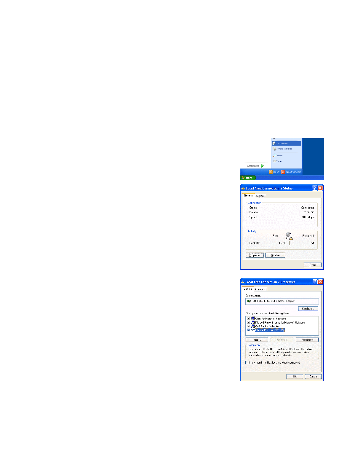
(1) Click on [Control Panel] under [Start] to open the Control Panel.
(2) In the Control Panel window, double click [Network and Dial-up
Connections] and the Networ k and Di al-u p Connect ions windo w will
open. Double click on [Local Area Setting] and the [Local Area
Connection Status] dialog will open. Click [Properties].
(3) In the [Local Area Connection Properties] dialog, click [Internet
Protocol] to select it and click the [Properties] button.
Page 4
3
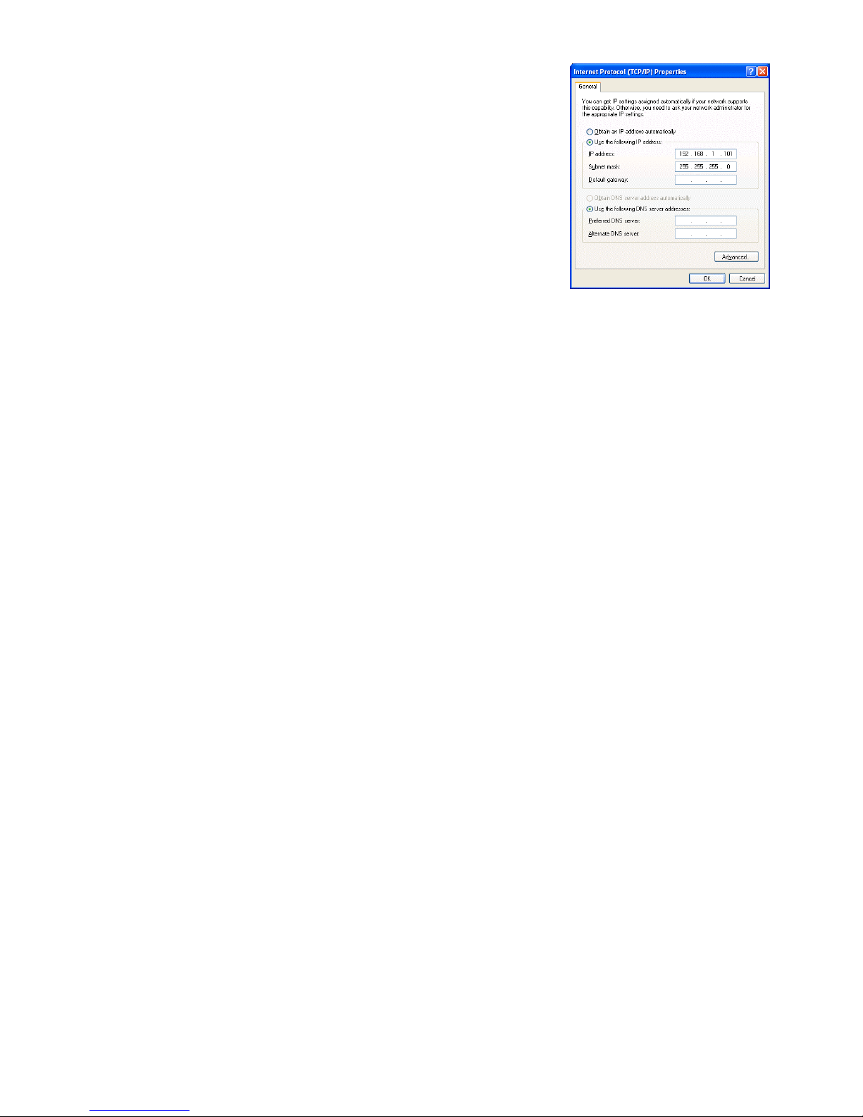
(4) In the [Internet Pr otocol (TCP/IP) Proper ties] dialog, click [Use the
following IP address] and enter the IP address (for example,
“192.168.1.101”) that you want to set in the IP address field.
You normally set [255.255.255.0] as the subnet mask.
Note: Ask your LAN admini stra tor to prov id e th e IP addresses and subnet
mask.
(5) Click the [OK] button to close this dialog, and then close the other
open dialogs to complete the network setting.
Page 5

4
2-2 Setting the Web Browser
Perform the necessary web browser settings to enable the web browser to connect to the G-50A.
Note: The settings and screen images used as examples in this manual are based on Internet Explorer 6.0.
2-2-1 Not connecting to the Internet
If the PC you use for monitoring air conditioners and performing operations is not going to be connected to the
Internet, use the procedure given below to set the web browser environment settings.
(1) Click the web browser menu item [Tools] and then click [Internet
Options…] to select that option.
(2) In the [Internet Options] tabbed dialog, click the [Connections] tab to
display that page.
(3) Select [Never dial a co nnection] in the Dial-u p settings section a nd
click the [OK] button to close the dialog.
2-2-2 Connecting to the Internet using a dial-up connection
If the PC you use for m onitoring air condit ion ers and p erf orming operat ions is goi ng to connec t to the I ntern et
via a dial-up connection, use the procedure given below to set the web browser environment settings.
By performing these s ettings, a m ess age will appear a sking whether or not to us e a dial-u p connec tion when
an Internet connection is necessary. In the case when you want to connect to the I nternet, connect to the
Internet by following the directions of this message.
(1) Click the web browser menu item [Tools] and then click [Internet
Options…] to select that option.
(2) In the [Internet Optio ns] tabbed dialog, click the [ Connections] tab to
display that page.
(3) Select [Dial whenever a network connection is not present] in the
Dial-up settings section and click the [OK] button to close the dialog.
Page 6

5
2-2-3 Connecting to the Internet using a proxy server (Using an existing LAN)
If the PC you use for monitoring a ir cond itioners and perf orm ing operations is goi ng to acc ess the Intern et vi a
proxy server by conn ecting to an exis ting L AN such a s a LAN within your com pany, use the proce dure give n
below to set the web browser environment settings.
By performing these settings, your PC will connect to a proxy server only when connecting to the Internet.
(1) Click the web browser menu item [Tools] and then click [Internet
Options…] to select that option.
(2) In the [Internet Optio ns] tabbed dialog, click the [ Connections] tab to
display that page.
(3) Select [Never dial a connection] in the Dial-up setting section.
(4) Click the [LAN Setting . . .] button in the Local Area Network (LAN)
settings section to display the Local Area Network (LAN) Settings
dialog.
(5) In the Local Are a N et wo rk (LAN) S etti ngs dialog, check [Bypass prox y
server for local addresses] and click the [Advanced...] button.
(6) Enter the IP address for the G-50A (e.g. 192.168.1.1) in the
Exceptions field of the Proxy Setting dialog and click the [OK] button to
close the dialog and then clos e the ot her op en d ia logs to c omplete the
setting.
Note: If connecting to more than one G-50A, you can specify multiple IP addresses
like [192.168.1.1; 192.168.1.2], however, it is also possible to use the
asterisk (*) and specify [192.168.1*].
Page 7

6
3 Performing Operations
Given below is an ex planation of ho w to connect to the G- 50A and how to m onitor and adjust the oper ation
condition of air conditioners. Follow the directions given here when performing operations.
Note: If the G-50A is restarted due to circumstances like a power interruption, wait until the screen on the G-50A main unit
displays the normal operation screen (it takes several minutes before the normal operati on screen is displayed) before
using a web browser to access the G-50A. If access is attempted while the G-50A is still starting up, the most recent data
might not be displayed or communication errors could occur.
Note: Default IP address of G-50A (GB-50A) is "192.168.1.1". (Factory setting)
3-1 Entering the User Name and the Password, and Connecti ng t o
the G-50A
(1) Enter the web page address in the address field of the web
browser as follows and pr ess the [Enter] key on the ke yboard. A
screen appears for login.
http://[IP address of the G-50A]/index.html
Note: For example, type “http://192.168.1.1/administrator.html” if the G-50A IP
address is [192.168.1.1].
(2) To make it easier to co nnect the next tim e, clic k the web brows er
menu item [Favor ites] and click [Add to F avorites] to select that
option and add the address to your Favorites folder. Once this
address is added to your Favorites folder, it is not ne cessary to
input the address of (1). You can simply select it from your
Favorites folder and the G-50A page will appear.
(3) Enter the user name and the pas sword in the login screen, and click the [Login] button. The screen for
monitoring the operati on co nditio n wil l appear . An exp lanat ion on how to perf orm operatio ns in the nor m al
operation screen begins from the next page.
Note: Consult your administrator for your user name and password.
Note: The Web page is displayed in the same language as the computer uses and it is also possible to display the Web page in
other languages by entering the following Web page addresses.
English : Htt p://[I P address of G-50]/en/index.html
German : Htt p://[I P address of G-50]/de/index.html
French : Htt p://[I P address of G-50]/fr/index.html
Spanish : Ht tp://[IP address of G-50]/es/index.html
Italian : Htt p:// [IP address of G-50]/i t/ i ndex.html
Russian : Ht tp://[IP address of G-50]/ru/index.html
Chinese : Http://[IP address of G-50]/zh/index.html
Japanese : Htt p://[I P address of G-50]/j a/index.html
Page 8

7
3-2 Checking the Operation Condition of the Air Conditioner
When you login correc tly using the Lo gin Screen, the screen used to m onitor the oper ation conditions of air
conditioner and gen eral equipment groups will appe ar. If you wish to operate an air c onditioner or general
equipment, click the group icon to switch to the operation screen.
Note: The operation condition display will not update automatically. If you wish to view the very latest condition, click [Update] on
each screen.
Item Description
Update to most recent
condition
Click [Update] to ensure the displayed items reflect the most recent operation condition.
Batch Operation Click [Batch Operation] if you want to perform an operation on all groups at once.
Group icon
The operation condition is indicated by the icon that is displayed. When you point to a group
icon with the mouse cursor, the group name is displayed. To switch to the operation screen,
click on the icon. The icons used to indicate the operation condition are shown below.
(1) Air conditioner group operation condition
(2) Ventilator (Lossnay) group operation condition
ON OFF Error Filter sign
Interlocked
ventilator ON
Interlocked
ventilator OFF
Schedule set Energy saving
Note: Other than 4-aiflow icons, 2-airflow or ceiling-suspended icons are also available.
Select the icon type on Initial Setting Web.
ON OFF Error Filter sign
Schedule set Energy saving
Batch operation
Click to perform an operation
on all groups at once.
Update to most recent
condition
Click to update the screen so
that the most recent condition is
shown.
Group icons
These icons are used to
indicate the operation condition
of an air conditioner or a
general equipment group.
Switch to the operation screen
by clicking the icon.
Set tempera ture dis play
The set temperature is
displayed here.
Room temperature display
The temperature of the
indoor unit’s intake is
displayed here.
Operation mode dis play
The operation mode is
displayed here.
Page 9

8
Item Description
Group icon
(3) General equipment group operation condition
Operation mode display The operation mode is displayed here.
Set temperature display The set temperature is displayed here.
Room temperature
display
The temperature of the indoor unit’s intake is displayed here.
Note: Because the temperature displayed here is of the indoor unit’s intake, it could be
different from the actual room temperature.
Note: The temperature display can be in either Celsius (°C) or Fahrenheit (°F) depending
on the setting.
ON OFF Error Schedule set
Note: Other than lighting icons, pump or card key icons are also available.
Page 10

9
3-3 Performing Air Conditioner Operations
Given below is an explanation of how to perform air conditioner or general equipment operations.
3-3-1 Performing air conditioner operations that target one group
When you click on a group icon in the op eration condition monitoring s creen, the operation scr een for that
group will appear . The item s shown in this scr een are the c urrent oper ation co nditions. Modif y the item s you
want to change and click [OK] to confirm the operatio n details. C lick [Cancel] to return to th e previous screen
without making any changes.
Item Description
ON/OFF Click [ON] or [OFF] to switch to ON or OFF.
Operation mode
Click [Cool], [Dry], [Fan], [Heat] or [Auto] to switch the operation mode.
If it is a ventilator group, select [Bypass], [Heat Recovery] or [Auto].
Note: Some unit models do not support certain operation modes. Unsupported operat ion modes are not
displayed.
Note: For K control models, all modes are displayed, however, choose only the modes that can be
operated.
Set temperature
Click to adjust the set temperature.
For [Cool] and [Dry], the setting range is 19 ~ 30°C/67 ~ 87°F, for [Heat] it is 17 ~ 28°C/63 ~
83°F, and for [Auto] it is 19 ~ 28°C/67 ~ 83°F.
Note: The temperature setting range varies depending on the unit model.
Note: If the setting range for set temperature is restricted, the temperature setting range will be smaller.
Note: If it is a ventilator model, this item is not displayed.
Air direction
Click to adjust the air direction.
Note: If it is a model that does not support air direction adjustment, this item is not displayed.
Note: If it is a model that does not support the swing feature, the swing option is not displayed.
Note:
The temperature display can be set to display in either Celsius (°C) or Fahrenheit (°F).
Fan speed
Click to adjust the fan speed.
Note: If it is a model that does not support fan speed adjustment, this item is not displayed.
Note: The number of available fan speeds will be 2 settings, 3 settings or 4 settings, depending on the
number of fan speeds supported by the model.
Filter sign
Click [Reset] to specify whether to reset the filter sign. It is set to reset when a green indicator is
displayed on the left of Reset ([
Reset]).
Note: If filter signs are not triggered in the group, then this item is not displayed.
Interlocked ventilator
ON/OFF
Click [ON] or [OFF] to switch interlocked ventilator ON or OFF.
Note: For groups that are not connected to an interlock ed ventilator, the items related to interlocked
ventilators are not displayed.
Fan speed of interlocked
ventilator
Click to adjust the fan speed of the interlocked ventilator.
Note: For groups that are not connected to an interlock ed ventilator, the items related to interlocked
ventilators are not displayed.
Operation Prohibition
mark
When air conditioners are centrally controlled, the central control mark will be displayed, and if
the prohibit setting has been set for any operations, the operation prohibition mark [ ] will be
displayed next to those operation items.
If the prohibit setting has been set for an item, it is not possible to operate that item.
Fan speed of
interlocked ventilator
Click to adjust the fan speed
of the interlocked ventilator.
Interlocked ventilator
ON/OFF
Click to switch interloc ked
ventilator ON or OFF.
Group name
The name of the group is
displayed here.
Fan speed
Click to adjust the fan speed.
OK button
Click to confirm the operation
details. You must press the O
K
button for the operation to take
effect.
Central control mark
This is displayed when the
units are centrally controlled
.
ON/OFF
Click to switch to ON or OFF.
Set temperature
Click to adjust the se t
temperature.
Operation mode
Click to switch the operation
mode.
Air direction
Click to adjust the air direction.
Filter sign
Click to reset the filter sign.
Cancel button
Click to cancel all operations.
Block name
The name of the block is
displayed here.
Operation prohibition
mark
If the prohibit setting has been
set for an operation, the
prohibition mark will be
displayed.
Page 11

10
3-3-2 Adjusting the operation conditions that target all groups
(1) Click [Batch Operation] from the operation condition monitoring
screen that displays all groups in a list. When air conditioner
groups, ventilator (LOSSNAY) groups, and general equipment
groups exist together in the List, a new screen will appear to
select the group. Click one of the [All air-conditioners], [All
LOSSNAY], or [Other Equ ipm ent] and t he scr een to s et th e batch
operation will appear.
If there is onl y air c on dit ion er grou ps or only LOSSNAY groups or
only general equipment groups, this selection screen will not
appear.
(2) After you have made the settings on the screen for batch
operation, click [OK] and only the items for which op eration was
performed will be sent to a ll the air conditioner units. To return to
the previous screen without performing any operations, click
[Cancel].
Note: If the setting range for set temperature is restricted, the temperature
setting range will be smaller.
Note: If operation of an item has been prohibited, then operation is not
possible for that item.
Page 12

WT03797X08
HEAD OFFICE: MITSUBISHI DENKI BLDG., 2-2-3, MARUNOUCHI, CHIYODA-KU, TOKYO 100-8310, JAPAN
 Loading...