

Page 1

CC-Link IE Field Network Basic
Reference Manual
Page 2

Page 3

SAFETY PRECAUTIONS
(1) Mitsubishi programmable controller ("the PRODUCT") shall be used in conditions;
i) where any problem, fault or failure occurring in the PRODUCT, if any, shall not lead to any major or serious accident;
and
ii) where the backup and fail-safe function are systematically or automatically provided outside of the PRODUCT for the
case of any problem, fault or failure occurring in the PRODUCT.
(2) The PRODUCT has been designed and manufactured for the purpose of being used in general industries.
MITSUBISHI SHALL HAVE NO RESPONSIBILITY OR LIABILITY (INCLUDING, BUT NOT LIMITED TO ANY AND ALL
RESPONSIBILITY OR LIABILITY BASED ON CONTRACT, WARRANTY, TORT, PRODUCT LIABILITY) FOR ANY
INJURY OR DEATH TO PERSONS OR LOSS OR DAMAGE TO PROPERTY CAUSED BY the PRODUCT THAT ARE
OPERATED OR USED IN APPLICATION NOT INTENDED OR EXCLUDED BY INSTRUCTIONS, PRECAUTIONS, OR
WARNING CONTAINED IN MITSUBISHI'S USER, INSTRUCTION AND/OR SAFETY MANUALS, TECHNICAL
BULLETINS AND GUIDELINES FOR the PRODUCT.
("Prohibited Application")
Prohibited Applications include, but not limited to, the use of the PRODUCT in;
• Nuclear Power Plants and any other power plants operated by Power companies, and/or any other cases in which the
public could be affected if any problem or fault occurs in the PRODUCT.
• Railway companies or Public service purposes, and/or any other cases in which establishment of a special quality
assurance system is required by the Purchaser or End User.
• Aircraft or Aerospace, Medical applications, Train equipment, transport equipment such as Elevator and Escalator,
Incineration and Fuel devices, Vehicles, Manned transportation, Equipment for Recreation and Amusement, and
Safety devices, handling of Nuclear or Hazardous Materials or Chemicals, Mining and Drilling, and/or other
applications where there is a significant risk of injury to the public or property.
Notwithstanding the above, restrictions Mitsubishi may in its sole discretion, authorize use of the PRODUCT in one or
more of the Prohibited Applications, provided that the usage of the PRODUCT is limited only for the specific
applications agreed to by Mitsubishi and provided further that no special quality assurance or fail-safe, redundant or
other safety features which exceed the general specifications of the PRODUCTs are required. For details, please
contact the Mitsubishi representative in your region.
(Read these precautions before using Mitsubishi Electric programmable controllers.)
Before using Mitsubishi Electric programmable controllers, please read the manuals for the products used and the relevant
manuals carefully and pay full attention to safety to handle the products correctly.
Make sure that the end users read this manual and then keep the manual in a safe place for future reference.
CONDITIONS OF USE FOR THE PRODUCT
INTRODUCTION
Thank you for purchasing the Mitsubishi Electric programmable controllers.
This manual describes the specifications, procedures before operation, system configuration, functions, and troubleshooting
of CC-Link IE Field Network Basic.
Before using the products, please read this manual carefully and develop familiarity with CC-Link IE Field Network Basic to
handle the products correctly.
When applying the program and circuit examples provided in this manual to an actual system, ensure the applicability and
confirm that it will not cause system control problems.
Please make sure that the end users read this manual.
In this manual, special relay (SM)/special register (SD) numbers and buffer memory addresses are described
using those of the MELSEC iQ-R series. When a different series is used, refer to the following.
Page 52 List of SM/SD/Buffer Memory Areas for CC-Link IE Field Network Basic
1
Page 4

CONTENTS
SAFETY PRECAUTIONS . . . . . . . . . . . . . . . . . . . . . . . . . . . . . . . . . . . . . . . . . . . . . . . . . . . . . . . . . . . . . . . . . . . .1
CONDITIONS OF USE FOR THE PRODUCT . . . . . . . . . . . . . . . . . . . . . . . . . . . . . . . . . . . . . . . . . . . . . . . . . . . .1
INTRODUCTION. . . . . . . . . . . . . . . . . . . . . . . . . . . . . . . . . . . . . . . . . . . . . . . . . . . . . . . . . . . . . . . . . . . . . . . . . . .1
TERMS . . . . . . . . . . . . . . . . . . . . . . . . . . . . . . . . . . . . . . . . . . . . . . . . . . . . . . . . . . . . . . . . . . . . . . . . . . . . . . . . . .4
CHAPTER 1 OVERVIEW 5
1.1 Features . . . . . . . . . . . . . . . . . . . . . . . . . . . . . . . . . . . . . . . . . . . . . . . . . . . . . . . . . . . . . . . . . . . . . . . . . . . . . . . .6
CHAPTER 2 SPECIFICATIONS 8
2.1 Performance Specifications . . . . . . . . . . . . . . . . . . . . . . . . . . . . . . . . . . . . . . . . . . . . . . . . . . . . . . . . . . . . . . . . 8
CHAPTER 3 FUNCTION LIST 10
CHAPTER 4 PROCEDURES BEFORE OPERATION 12
CHAPTER 5 SYSTEM CONFIGURATION 14
5.1 CC-Link IE Field Network Basic System Configuration. . . . . . . . . . . . . . . . . . . . . . . . . . . . . . . . . . . . . . . . . 14
Access range. . . . . . . . . . . . . . . . . . . . . . . . . . . . . . . . . . . . . . . . . . . . . . . . . . . . . . . . . . . . . . . . . . . . . . . . . . . .15
Number of link points. . . . . . . . . . . . . . . . . . . . . . . . . . . . . . . . . . . . . . . . . . . . . . . . . . . . . . . . . . . . . . . . . . . . . .16
5.2 Product List . . . . . . . . . . . . . . . . . . . . . . . . . . . . . . . . . . . . . . . . . . . . . . . . . . . . . . . . . . . . . . . . . . . . . . . . . . . . 17
CPU modules can be used as the master station . . . . . . . . . . . . . . . . . . . . . . . . . . . . . . . . . . . . . . . . . . . . . . . . 17
Modules and devices can be used as a slave station . . . . . . . . . . . . . . . . . . . . . . . . . . . . . . . . . . . . . . . . . . . . .18
Wiring products . . . . . . . . . . . . . . . . . . . . . . . . . . . . . . . . . . . . . . . . . . . . . . . . . . . . . . . . . . . . . . . . . . . . . . . . . .18
CHAPTER 6 PROGRAMMING 19
6.1 Interlock Programs of Cyclic Transmission . . . . . . . . . . . . . . . . . . . . . . . . . . . . . . . . . . . . . . . . . . . . . . . . . .19
Program using labels. . . . . . . . . . . . . . . . . . . . . . . . . . . . . . . . . . . . . . . . . . . . . . . . . . . . . . . . . . . . . . . . . . . . . .19
Program using devices . . . . . . . . . . . . . . . . . . . . . . . . . . . . . . . . . . . . . . . . . . . . . . . . . . . . . . . . . . . . . . . . . . . .21
CHAPTER 7 FUNCTIONS 22
7.1 Cyclic Transmission . . . . . . . . . . . . . . . . . . . . . . . . . . . . . . . . . . . . . . . . . . . . . . . . . . . . . . . . . . . . . . . . . . . . .22
Data flow and link device assignment . . . . . . . . . . . . . . . . . . . . . . . . . . . . . . . . . . . . . . . . . . . . . . . . . . . . . . . . .22
Link refresh . . . . . . . . . . . . . . . . . . . . . . . . . . . . . . . . . . . . . . . . . . . . . . . . . . . . . . . . . . . . . . . . . . . . . . . . . . . . . 26
Operation of the link scan . . . . . . . . . . . . . . . . . . . . . . . . . . . . . . . . . . . . . . . . . . . . . . . . . . . . . . . . . . . . . . . . . . 28
Group number setting . . . . . . . . . . . . . . . . . . . . . . . . . . . . . . . . . . . . . . . . . . . . . . . . . . . . . . . . . . . . . . . . . . . . . 30
Input and output status when failure occurs . . . . . . . . . . . . . . . . . . . . . . . . . . . . . . . . . . . . . . . . . . . . . . . . . . . .32
Output status for CPU STOP. . . . . . . . . . . . . . . . . . . . . . . . . . . . . . . . . . . . . . . . . . . . . . . . . . . . . . . . . . . . . . . . 32
7.2 Reserved Station Specification . . . . . . . . . . . . . . . . . . . . . . . . . . . . . . . . . . . . . . . . . . . . . . . . . . . . . . . . . . . . 33
CHAPTER 8 PARAMETER SETTINGS 34
8.1 Settings for the Master Station in MELSEC iQ-R/MELSEC iQ-F . . . . . . . . . . . . . . . . . . . . . . . . . . . . . . . . . .34
CC-Link IEF Basic Setting. . . . . . . . . . . . . . . . . . . . . . . . . . . . . . . . . . . . . . . . . . . . . . . . . . . . . . . . . . . . . . . . . . 34
8.2 Settings for the Master Station in MELSEC-Q/L. . . . . . . . . . . . . . . . . . . . . . . . . . . . . . . . . . . . . . . . . . . . . . . 41
CC-Link IEF Basic Setting. . . . . . . . . . . . . . . . . . . . . . . . . . . . . . . . . . . . . . . . . . . . . . . . . . . . . . . . . . . . . . . . . . 41
2
CHAPTER 9 TROUBLESHOOTING 43
9.1 CC-Link IE Field Network Basic Diagnostics . . . . . . . . . . . . . . . . . . . . . . . . . . . . . . . . . . . . . . . . . . . . . . . . . 43
9.2 Troubleshooting by Symptom . . . . . . . . . . . . . . . . . . . . . . . . . . . . . . . . . . . . . . . . . . . . . . . . . . . . . . . . . . . . .45
Page 5

9.3 Acquiring diagnostic information of slave stations. . . . . . . . . . . . . . . . . . . . . . . . . . . . . . . . . . . . . . . . . . . .48
How to acquire diagnostic information. . . . . . . . . . . . . . . . . . . . . . . . . . . . . . . . . . . . . . . . . . . . . . . . . . . . . . . . . 48
Program for acquiring diagnostic information . . . . . . . . . . . . . . . . . . . . . . . . . . . . . . . . . . . . . . . . . . . . . . . . . . .48
APPENDICES 52
Appendix 1 List of SM/SD/Buffer Memory Areas for CC-Link IE Field Network Basic . . . . . . . . . . . . . . . . . . . . . 52
Appendix 2 Processing Time . . . . . . . . . . . . . . . . . . . . . . . . . . . . . . . . . . . . . . . . . . . . . . . . . . . . . . . . . . . . . . . . . . .55
Link scan time . . . . . . . . . . . . . . . . . . . . . . . . . . . . . . . . . . . . . . . . . . . . . . . . . . . . . . . . . . . . . . . . . . . . . . . . . . .56
Transmission delay time . . . . . . . . . . . . . . . . . . . . . . . . . . . . . . . . . . . . . . . . . . . . . . . . . . . . . . . . . . . . . . . . . . . 57
Appendix 3 Added and Enhanced Functions . . . . . . . . . . . . . . . . . . . . . . . . . . . . . . . . . . . . . . . . . . . . . . . . . . . . . .58
INDEX 60
REVISIONS. . . . . . . . . . . . . . . . . . . . . . . . . . . . . . . . . . . . . . . . . . . . . . . . . . . . . . . . . . . . . . . . . . . . . . . . . . . . . .62
WARRANTY . . . . . . . . . . . . . . . . . . . . . . . . . . . . . . . . . . . . . . . . . . . . . . . . . . . . . . . . . . . . . . . . . . . . . . . . . . . . .63
TRADEMARKS . . . . . . . . . . . . . . . . . . . . . . . . . . . . . . . . . . . . . . . . . . . . . . . . . . . . . . . . . . . . . . . . . . . . . . . . . . .64
CONTENTS
3
Page 6

TERMS
Unless otherwise specified, this manual uses the following terms.
Term Description
Buffer memory Memory in a module for storing data such as setting values and monitored values
Cyclic transmission A function by which data are periodically exchanged among stations on the same network using link
Disconnection A process of stopping data link if a data link error occurs
Label A label that represents a device in a given character string
Link device A device (RX, RY, RWr, or RWw) in a CPU module for the purpose of communicating with slave stations
Link refresh Automatic data transfer between a user device and a link device
Link scan (link scan time) The master station of CC-Link IE Field Network Basic sends requests to all slave stations. After
Master station A station that controls the entire CC-Link IE Field Network Basic. Only one master station can be used
RAS The abbreviation for Reliability, Availability, and Serviceability. This term refers to usability of automated
Reference response time The time taken from when a slave station of CC-Link IE Field Network Basic has received a request
Reserved station A station reserved for future use. This station is not actually connected on CC-Link IE Field Network
Return A process of restarting data link when a station recovers from an error
Slave station A station that performs cyclic transmission with the master station on CC-Link IE Field Network Basic. I/
SLMP The abbreviation for Seamless Message Protocol. This protocol is used to access an SLMP-compatible
Subnet mask A number used to logically divide one network into multiple subnetworks and manage them easily. The
User device A device (X, Y, M, D, or others) in a CPU module
devices on CC-Link IE Field Network Basic
receiving responses from all the slave stations, the master station sends next requests. The time taken
from when requests are sent to when the next requests are started to send by the master station.
in a network.
equipment.
from the master station to when the slave station send a response to the master station.
Basic, but counted as a connected station
O signals in units of bits and I/O data in units of words are exchanged.
device or a programmable controller connected to an SLMP-compatible device from an external device.
following Ethernet network systems can be configured:
• A small-scale Ethernet network system in which multiple network devices are connected
• A medium- or large-scale network system in which multiple small-scale network systems are
connected via routers or other network communication devices
4
Page 7
1 OVERVIEW
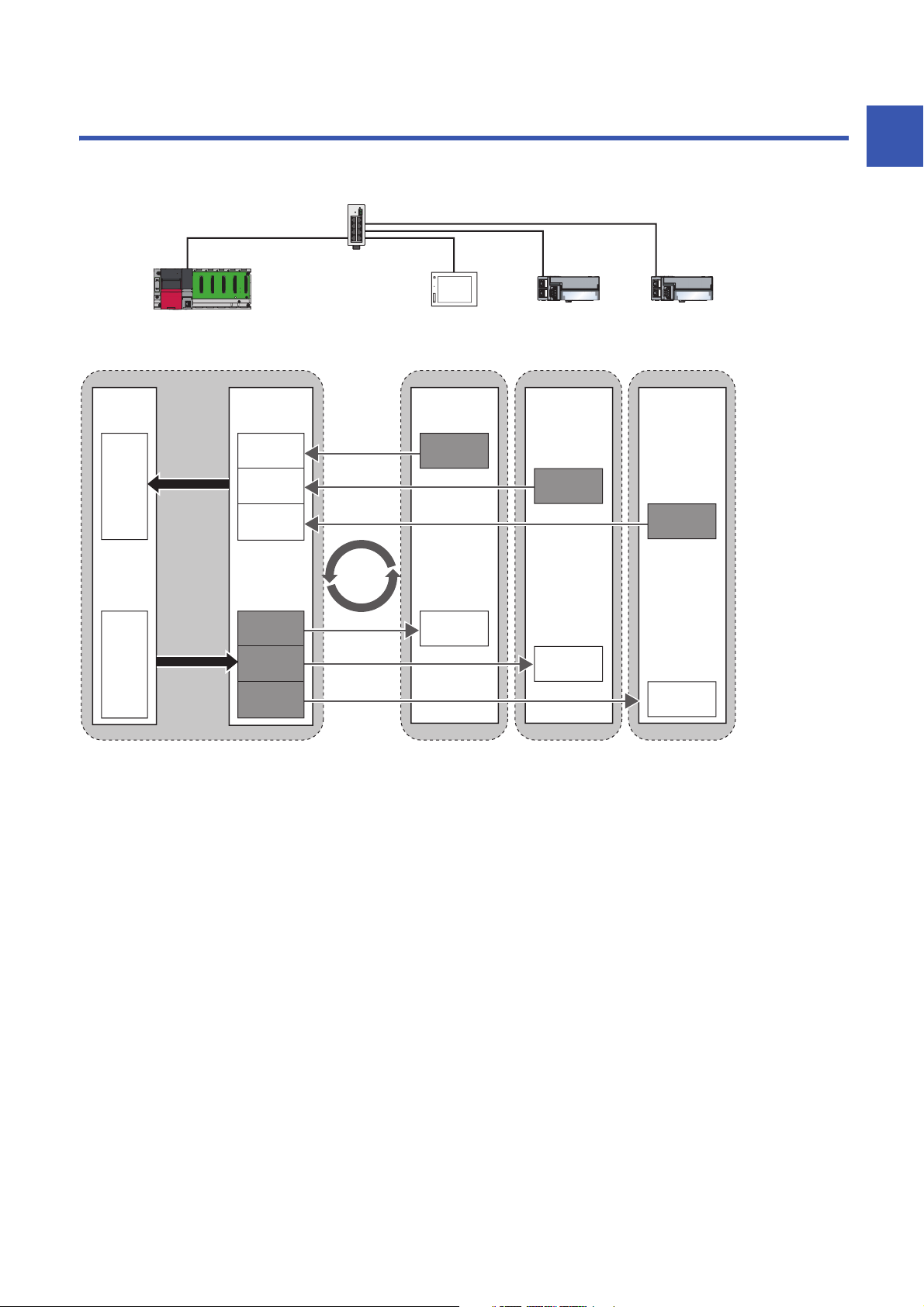
RX, RWr
RX, RWr
RX, RWr
RY, RWw
RY, RWw
RY, RWw
RX, RWr
RY, RWw
192.168.3.39 192.168.3.1 192.168.3.2 192.168.3.3
Device
Device
Link
refresh
Link
refresh
Link
scan
CC-Link IE Field Network Basic is an factory automation network using the standard Ethernet.
Data is periodically communicated between the master station and slave stations using link devices (cyclic transmission).
1
For details on cyclic transmission, refer to the following.
Page 22 Cyclic Transmission
1 OVERVIEW
5
Page 8
1.1 Features
FTP
HTTP
Cost saving of the system
The CPU module with built-in Ethernet port is the master station of CC-Link IE Field Network Basic. Since a dedicated
network module is not used, the cost for the system can be reduced.
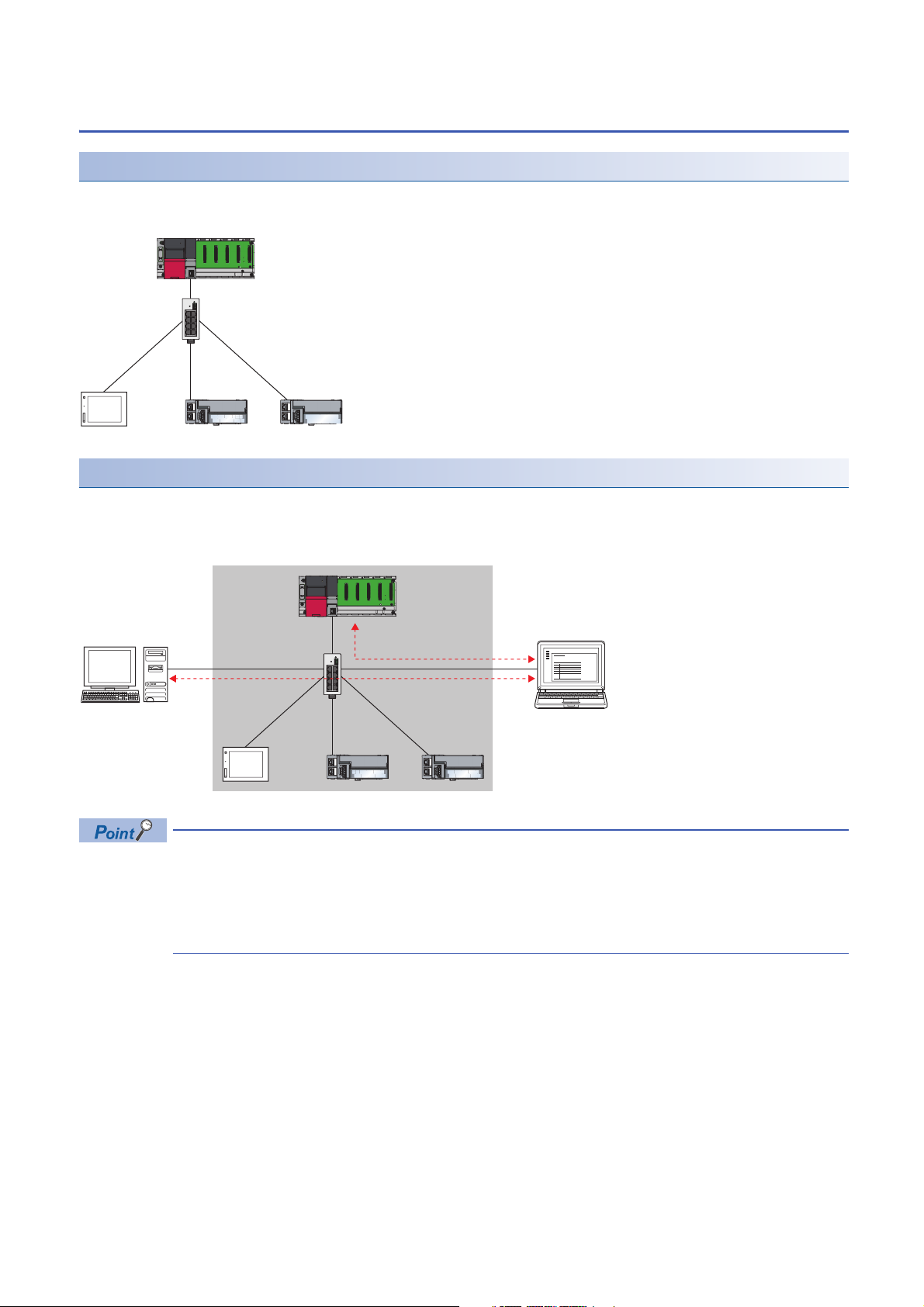
Using different protocols
CC-Link IE Field Network Basic can be used with other standard Ethernet protocols. Thus, a network system in which different
protocols such as FTP, HTTP, and SLMP coexist can be configured.
Moreover, a gateway is not required for communications with personal computers and other information devices.
6
The link scan time of cyclic transmission is increased by executing following functions:
• The built-in Ethernet functions such as FTP. socket communications, and SLMP communications
• Communications with other Ethernet devices on the same line
Use the built-in Ethernet function above or other Ethernet devices so that the system being used is not
affected. ( Page 47 When access to the CPU module is slow)
1 OVERVIEW
1.1 Features
Page 9
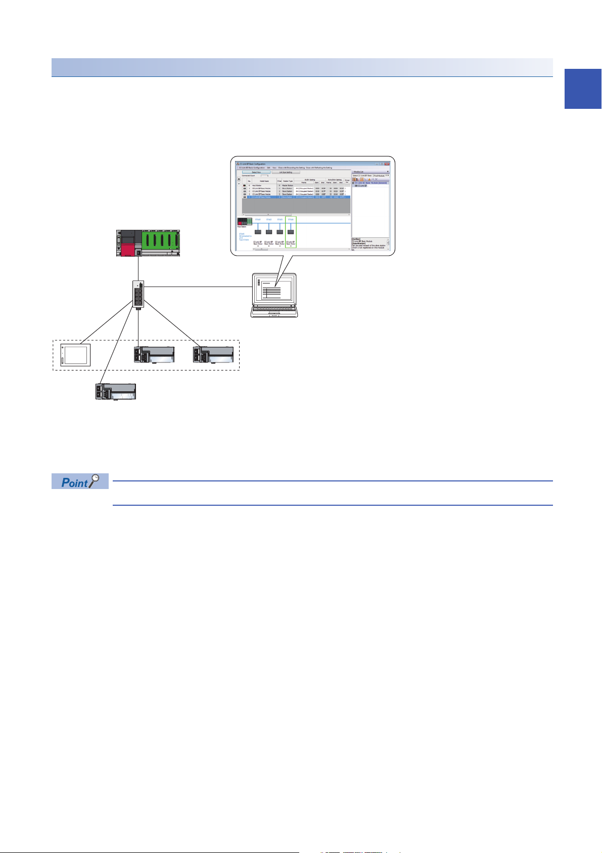
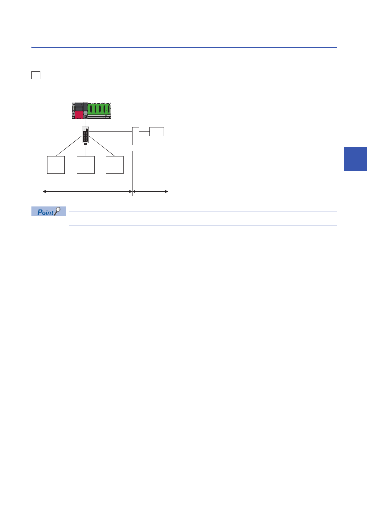
Easy system configuration
(2)
(3)
(1)
Configure the entire network of CC-Link IE Field Network Basic in the master station. To perform the cyclic transmission, set
an IP address and subnet mask to each slave station. Setting the information of the master station to each slave station is not
required.
In addition, since the devices are connected in star topology, there are no restrictions on the connection order or connection
position of devices. Thus, it is also easy to connect a new slave station.
1
(1) Configure the entire network of CC-Link IE Field Network Basic in the master station.
(2) Set the IP address and subnet mask.
(3) There are no restrictions on the connection order or connection position when a new slave station is added on the same network. Changing the setting for
existing slave stations is not required.
CC-Link IE Field Network Basic does not require setting of the connection with the slave station.
1 OVERVIEW
1.1 Features
7
Page 10

2 SPECIFICATIONS
This chapter describes the specifications of CC-Link IE Field Network Basic.
2.1 Performance Specifications
The following table lists the performance specifications of CC-Link IE Field Network Basic.
Item Specifications
MELSEC iQ-R MELSEC iQ-F MELSEC-Q MELSEC-L
Number of connectable modules per
network
Number of stations occupied by a slave station 1 to 4
Maximum number of link points per
network
Maximum number
of link points per
station
UDP port number used in the cyclic transmission 61450
UDP port number used in the automatic detection of connected
device
Transmission
specifications
Network topology Star topology
Connection cable Ethernet cable compliant with the 100BASE-TX standard ( Page 18 Ethernet cable)
Maximum station-to-station distance 100m (ANSI/TIA/EIA-568-B (Category 5e) compliant)
Overall cable distance Depends on the system configuration
Master station RX 4096
Slave station RX 64 (1 station occupied)
Data transmission speed 100Mbps
Number of cascade
connections
Master station 1
Slave station
RX 4096
RY 4096
RWr 2048
RWw 2048
RY 4096
RWr 2048
RWw 2048
RY 64 (1 station occupied)
RWr 32 (1 station occupied)
RWw 32 (1 station occupied)
100BASE-TX For the number of the connectable stages when using a switching hub, check with the
*1
64 (16 4 groups)*2664 (16 4 groups)*316
*2
*2
*2
*2
*2
*2
*2
*2
128 (2 station occupied)
192 (3 station occupied)
256 (4 station occupied)
128 (2 station occupied)
192 (3 station occupied)
256 (4 station occupied)
64 (2 station occupied)
96 (3 station occupied)
128 (4 station occupied)
64 (2 station occupied)
96 (3 station occupied)
128 (4 station occupied)
Master station: An unused port number is assigned automatically.
Slave station: 61451
manufacturer of the switching hub used.
384 4096
384 4096
192 2048
192 2048
384 4096
384 4096
192 2048
192 2048
*3
*3
*3
*3
*3
*3
*3
*3
1024
1024
512
512
1024
1024
512
512
*3
*3
*3
*3
*3
*3
*3
*3
*3
*1 It is the maximum number of connectable modules for a slave station controlled by the master station. It varies depending on the number
of stations occupied by a slave station. Ensure that the total number of occupied stations does not exceed the maximum number of
connectable modules.
*2 When using the programmable controller CPU (except for the R00CPU, R01CPU, and R02CPU) with the firmware version "28" or
earlier, refer to the following.
Page 9 Performance specifications vary depending on the version of the CPU module
*3 When using the CPU module with serial number earlier than "19042" (first five digits), refer to the following.
Page 9 Performance specifications vary depending on the version of the CPU module
2 SPECIFICATIONS
8
2.1 Performance Specifications
Page 11

Performance specifications vary depending on the version of the CPU module
The following table lists performance specifications vary in the case below.
• MELSEC iQ-R: When the programmable controller CPU (except for the R00CPU, R01CPU, and R02CPU) with the
firmware version earlier than "28" is used.
• MELSEC-Q, MELSEC-L: When the CPU module with serial number earlier than "19042" (first five digits) is used
Item Specifications
MELSEC iQ-R MELSEC-Q MELSEC-L
Number of connectable modules per
network
Maximum number of link points per
network
Maximum number
of link points per
station
Master station RX 1024 1024 512
Slave station 16 16 8
RX 1024 1024 512
RY 1024 1024 512
RWr 512 512 256
RWw 512 512 256
RY 1024 1024 512
RWr 512 512 256
RWw 512 512 256
2
2 SPECIFICATIONS
2.1 Performance Specifications
9
Page 12

3 FUNCTION LIST
This chapter describes the functions can be used in the master station on CC-Link IE Field Network Basic.
Some functions have restrictions on versions of the CPU module of each series or GX Works3/CW
Configurator/GX Works2.
( Page 58 Added and Enhanced Functions)
iQ-R: MELSEC iQ-R, iQ-F: MELSEC iQ-F, Q: MELSEC-Q, L: MELSEC-L
: Available, : Not available
Cyclic transmission
Function Description Availability
iQ-R iQ-F Q L
Data communication using link devices
(RX/RY/RWr/RWw)
Link refresh Automatically transfers data between devices and link devices of the master
Cyclic data integrity assurance Assures cyclic data integrity in station-based units.
Group number setting Divides slave stations into groups by setting a group number to each slave
Input and output status when failure
occurs
Output status for CPU STOP Clears or holds cyclic data output when the CPU module is set to STOP state.
Periodically performs data communication between the master station and slave
stations using link devices (RX/RY/RWr/RWw). ( Page 22 Data flow and link
device assignment)
station. ( Page 26 Link refresh)
station and each of groups performs the cyclic transmission. By organizing
groups separating slave stations with shorter response processing time from
ones with longer response processing time, the differences of the reference
response times of each slave station does not badly affect the cyclic
transmission. ( Page 30 Group number setting)
Clears or holds status of input from a data link faulty station and output status of
cyclic data if a stop error occurs in the CPU module ( Page 32 Input and
output status when failure occurs)
( Page 32 Output status for CPU STOP)
RAS
Function Description Availability
iQ-R iQ-F Q L
Slave station disconnection Disconnects the corresponding slave station if no response is received within the
timeout time or number of times for disconnection detection set in the slave
station disconnection detection settings. ( Page 39 Link Scan Setting)
Automatic return Automatically returns a disconnected station to the network and restarts the data
link when the station returns to normal.
Diagnostics
Function Description Availability
iQ-R iQ-F Q L
CC-Link IE Field Network Basic
diagnostics
Checks the status of CC-Link IE Field Network Basic. ( Page 43 CC-Link IE
Field Network Basic Diagnostics)
Others
Function Description Availability
iQ-R iQ-F Q L
Reserved station specification Reserves a station (a station not actually connected but counted as a connected
station) for future use. A reserved station is not detected as a faulty station even
though it is not actually connected. ( Page 33 Reserved Station
Specification)
10
3 FUNCTION LIST
Page 13

MEMO
3
3 FUNCTION LIST
11
Page 14

4 PROCEDURES BEFORE OPERATION
This chapter describes the procedures before operation.
1. Configuring a network system
Configure a network system. ( Page 14 SYSTEM CONFIGURATION, Page 13 Wiring precautions)
2. Setting parameters of the master station
• IP address setting (such as IP address, subnet mask)
• CC-Link IEF Basic setting ( Page 34 Settings for the Master Station in MELSEC iQ-R/MELSEC iQ-F, Page 41
Settings for the Master Station in MELSEC-Q/L)
Actually connected devices can be detected by the automatic detection of connected device and reflected in
the network configuration setting. ( Page 36 Automatic detection of connected device)
In the network configuration setting, communication settings, such as IP addresses and subnet masks, and
writing/reading parameters that are inherent in the slave stations can also be performed to the slave stations.
(Some slave stations does not support these features.)
3. Configure the necessary settings of the slave station such as the IP address and subnet mask. (Manual for the slave
station used)
4. Write parameters to the CPU module on the master station. (Operating manual for the tool used)
5. Start up the slave stations.
6. Cyclic transmission starts if the CPU module on the master station is powered off and on or reset.
7. Diagnosing a network
Check the status of a network by executing the CC-Link IE Field Network Basic diagnostics. ( Page 43 CC-Link IE Field
Network Basic Diagnostics)
8. Programming
Create a program. For details, refer to the following.
Page 19 PROGRAMMING
12
4 PROCEDURES BEFORE OPERATION
Page 15

Wiring precautions
• Place the Ethernet cables in a duct or clamp them. If not, dangling cable may swing or inadvertently be pulled, resulting in
damage to the module or cables or malfunction due to poor contact.
• Do not touch the core of the cable-side or module-side connector, and protect it from dirt or dust. If oil from your hand, dirt
or dust is attached to the core, it can increase transmission loss, arising a problem in data link.
• Check that the Ethernet cable is not disconnected or not shorted and there is no problem with the connector connection.
• Do not use Ethernet cables with broken latches. Doing so may cause the cable to unplug or malfunction.
• Hold the connector part when connecting and disconnecting the Ethernet cable. Pulling the cable connected to the module
may result in malfunction or damage to the module or cable.
• For connectors without Ethernet cable, attached connector cover should be placed to prevent foreign matter such as dirt or
dust.
• The maximum segment length of the Ethernet cable is 100m. However, the length may be shorter depending on the
operating environment of the cable. For details, contact the manufacturer of the cable used.
• The bending radius of the Ethernet cable is limited. For details, check the specifications of the Ethernet cable to be used.
• For a cascade connection, recommended number of levels is up to three. If connected four levels or more, a packet loss
caused by switching hubs is more likely to occur.
4
4 PROCEDURES BEFORE OPERATION
13
Page 16
5 SYSTEM CONFIGURATION
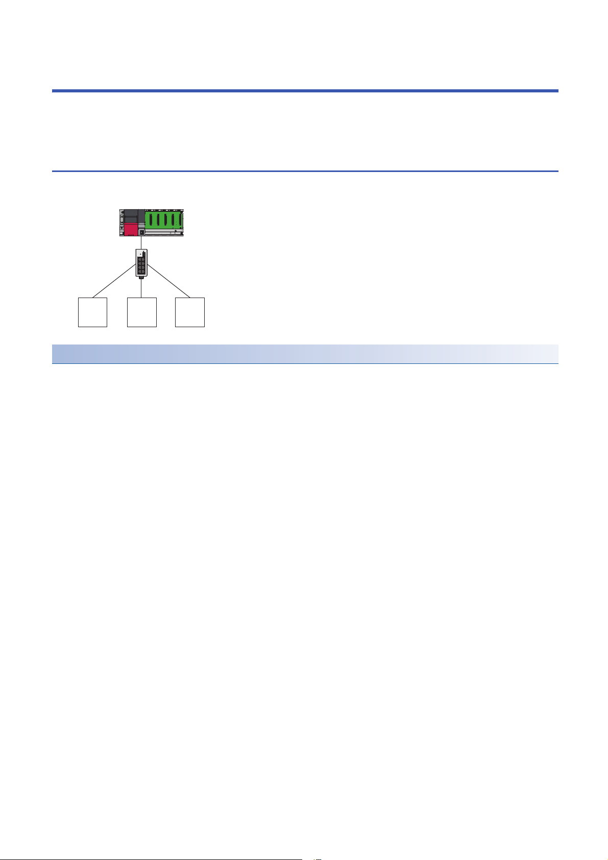
Master station
Switching hub
Slave station
This chapter describes the system configuration of CC-Link IE Field Network Basic.
5.1 CC-Link IE Field Network Basic System
Configuration
Configure a network system using modules and partner products supporting CC-Link IE Field Network Basic.
Network topology
Use a standard Ethernet cable and switching hub and connect slave stations in star topology.
14
5 SYSTEM CONFIGURATION
5.1 CC-Link IE Field Network Basic System Configuration
Page 17
Access range
Ex.
192.168.3.1 192.168.3.2 192.168.3.3
192.168.4.2
192.168.3.39
Master station
Switching hub
Slave station
Router
Accessible Not accessible
The access range of CC-Link IE Field Network Basic is within the same network address of Ethernet. The device connected
beyond a router is not accessible.
When the subnet mask is 255.255.255.0 and the network address is 192.168.3.
Use the same subnet mask value and do not assign the same IP address for each slave station.
5
5 SYSTEM CONFIGURATION
5.1 CC-Link IE Field Network Basic System Configuration
15
Page 18
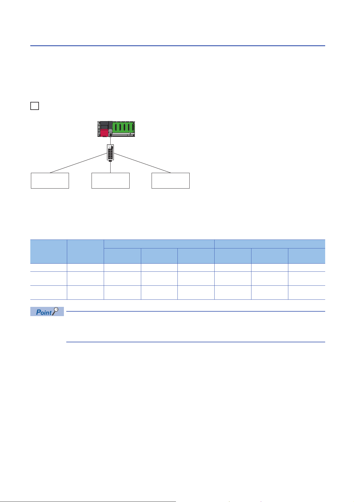
Number of link points
Ex.
Master station
Slave station 3Slave station 1 Slave station 2
The number of link points per slave station is 64 points for RX/RY and 32 points for RWr/RWw. ( Page 8 Performance
Specifications)
However, by changing the number of occupied stations, RX/RY can be set to a maximum of 256 points in increments of 64
points and RWr/RWw can be set to a maximum of 128 points in increments of 32 points. For details on the number of
occupied stations (whether or not the number can be changed), refer to the manual for the slave station used.
If the number of link points for the slave station is changed, the assignment range and station number are changed.
• Slave station 1: 1 station occupied
• Slave station 2: 2 stations occupied
• Slave station 3: 4 stations occupied
The following table lists the number of link points.
Slave station Number of
occupied
stations
116403F3201F
2 2 stations
occupied
3 4 stations
occupied
RX/RY RWr/RWw
Number of
points
128 40 BF 64 20 5F
256 C0 1BF 128 60 DF
Start End Number of
points
Start End
16
Setting the number of link points for a slave station to 2 stations occupied means that two slave stations are
connected. Thus, if the number of link points is increased, the number of connectable slave stations per
network is decreased.
5 SYSTEM CONFIGURATION
5.1 CC-Link IE Field Network Basic System Configuration
Page 19

5.2 Product List
This section describes the products which configure a CC-Link IE Field Network Basic system.
CPU modules can be used as the master station
The following table lists the CPU modules which can be used as the master station of CC-Link IE Field Network Basic.
To check the firmware version of these CPU modules, refer to the following.
Page 58 Added and Enhanced Functions
MELSEC iQ-R
Product name Model name
Programmable controller CPU R00CPU, R01CPU, R02CPU, R04CPU, R04ENCPU, R08CPU, R08ENCPU, R16CPU, R16ENCPU,
R32CPU, R32ENCPU, R120CPU, R120ENCPU
C Controller module R12CCPU-V
MELSEC iQ-F
Product name Model name
FX5U CPU module FX5U-32MR/ES, FX5U-32MT/ES, FX5U-32MT/ESS, FX5U-64MR/ES, FX5U-64MT/ES, FX5U-64MT/ESS,
FX5U-80MR/ES, FX5U-80MT/ES, FX5U-80MT/ESS, FX5U-32MR/DS, FX5U-32MT/DS, FX5U-32MT/DSS,
FX5U-64MR/DS, FX5U-64MT/DS, FX5U-64MT/DSS, FX5U-80MR/DS, FX5U-80MT/DS, FX5U-80MT/DSS
FX5UC CPU module FX5UC-32MT/D, FX5UC-32MT/DSS, FX5UC-64MT/D, FX5UC-64MT/DSS, FX5UC-96MT/D, FX5UC-
96MT/DSS
5
MELSEC-Q
Product name Model name
High-speed Universal model QCPU Q03UDVCPU, Q04UDVCPU, Q06UDVCPU, Q13UDVCPU, Q26UDVCPU
MELSEC-L
Product name Model name
Built-in Ethernet port LCPU L02CPU, L02CPU-P, L06CPU, L06CPU-P, L26CPU, L26CPU-P, L26CPU-BT, L26CPU-PBT
5 SYSTEM CONFIGURATION
5.2 Product List
17
Page 20

Modules and devices can be used as a slave station
For modules and devices which can be used as a slave station of CC-Link IE Field Network Basic, refer to the manual for
each module and device.
Use the CPU modules listed in the previous page (the CPU modules can be used as the master station) only
as the master station. ( Page 17 CPU modules can be used as the master station)
Wiring products
This section describes the wiring products used in CC-Link IE Field Network Basic.
Ethernet cable
Use an Ethernet cable which conforms to the following standards.
Ethernet cable Connector Standard
Category 5 or higher, (STP) straight cable RJ45 connector • IEEE802.3 (100BASE-TX)
Category 5 or 5e, (STP) crossover cable
Hub
Use hubs which satisfy all the following conditions. If hubs not satisfying the conditions are used, operation is not guaranteed.
• IEEE802.3 (100BASE-TX) compliant
• The auto MDI/MDI-X function equipped
• The auto-negotiation function equipped
• Switching hub (layer 2 switch)
*1 A repeater hub cannot be used.
For switching hubs that can be used for CC-Link IE Field Network Basic, refer to the following.
Applicable products (switching hubs) for CC-Link IE Field Network Basic module (FA-A-0234)
*1
• ANSI/TIA/EIA-568-B (Category 5)
18
5 SYSTEM CONFIGURATION
5.2 Product List
Page 21
6 PROGRAMMING
This chapter describes the programming of CC-Link IE Field Network Basic.
When the C Controller module is used, refer to the following.
MELSEC iQ-R C Controller Module User's Manual (Application)
6.1 Interlock Programs of Cyclic Transmission
When creating a cyclic transmission program, configure an interlock such that the processing is performed when normal cyclic
transmission between the master station and slave stations is performed.
For details on SM/SD, refer to the following.
Page 52 List of SM/SD/Buffer Memory Areas for CC-Link IE Field Network Basic
Program using labels
A program using labels is provided below.
Labels used in the program
■Module label
The following module labels are used.
Module label Description Device
MELSEC iQ-R MELSEC iQ-F
RCPU.stSM.bSts_CyclicTransmission FX5CPU.stSM.bSts_CyclicTransmission Cyclic transmission status SM1536
RCPU.stSD.bnSts_CyclicTransmission_Station[1] FX5CPU.stSD.bnSts_CyclicTransmission_Station[1] Cyclic transmission status of
each station (station No.1)
RCPU.stSD.bnSts_CyclicTransmission_Station[2] FX5CPU.stSD.bnSts_CyclicTransmission_Station[2] Cyclic transmission status of
each station (station No.2)
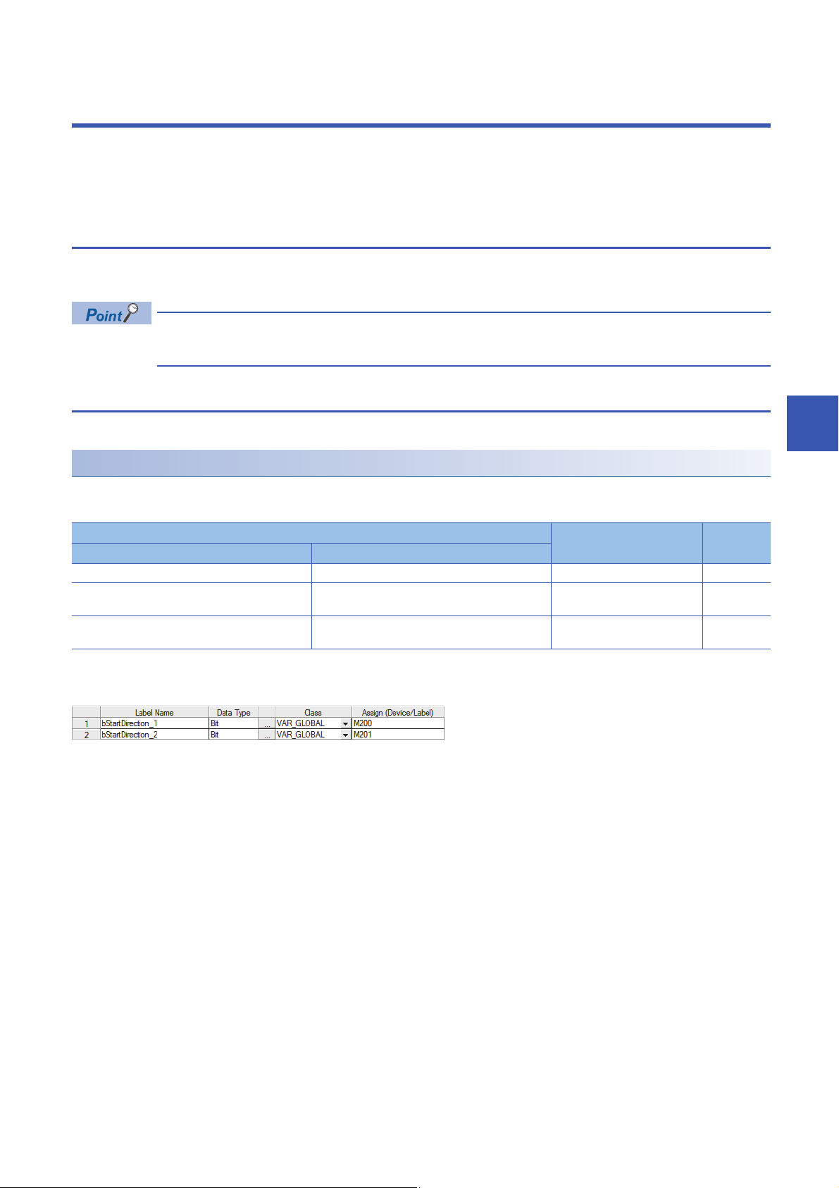
■Labels to be defined
Define global labels as follows.
SD1536.0
SD1536.1
6
6 PROGRAMMING
6.1 Interlock Programs of Cyclic Transmission
19
Page 22

Program example
Communication program with station No.1
Communication program with station No.2
The following is a program example of MELSEC iQ-R series.
20
6 PROGRAMMING
6.1 Interlock Programs of Cyclic Transmission
Page 23

Program using devices
Communication program with station No.1
Communication program with station No.2
A program using devices is provided below.
Devices used in the program
The following devices are used.
Device Description
MELSEC iQ-R MELSEC iQ-F MELSEC-Q MELSEC-L
SM1536 SM1536 SM1700 SM1700 Cyclic transmission status
SD1536.0 SD1536.0 SD1700.0 SD1700.0 Cyclic transmission status of each station
(station No.1)
SD1536.1 SD1536.1 SD1700.1 SD1700.1 Cyclic transmission status of each station
(station No.2)
Program example
The following is a program example of MELSEC-Q series.
6
6 PROGRAMMING
6.1 Interlock Programs of Cyclic Transmission
21
Page 24

7 FUNCTIONS
RX, RWr
RX, RWr
RX, RWr
RY, RWw
RY, RWw
RY, RWw
RX, RWr
RY, RWw
M0
Y
Ò
×
×
×
Ô
Ô
Ô
Ö
Õ
Ó
Ø
X0
Ù
Slave station 1
*1
Slave station 2
*1
Slave station 3
*1
Slave
station 1
Slave
station 2
Slave
station 3
Device
Device
Slave
station 1
Slave
station 2
Slave
station 3
Link
refresh
Link
refresh
Link
scan
Master station
This chapter describes the functions of CC-Link IE Field Network Basic.
When the C Controller module is used, refer to the following.
MELSEC iQ-R C Controller Module User's Manual (Application)
7.1 Cyclic Transmission
This function periodically performs data communication between the master station and slave stations using link devices.
Data flow and link device assignment
The following figure shows the data flow of communications using link devices between the master station and slave stations.
22
: Area where data is sent to other stations
*1 The slave station order is the same as the order set in the network configuration setting. ( Page 35 Network Configuration Settings)
• Output from the master station
The devices of the master station turn on.
The status of the devices of the master station is stored in the link devices (RY, RWw) of the master station by link refresh.
The status of link devices (RY, RWw) of the master station is stored in the link devices (RY, RWw) of each slave station by link scan.
The status of the link devices (RY, RWw) of the slave station is output to external devices.
• Input from the slave station
The status of external devices is stored in the link devices (RX, RWr) of each slave station.
The status of the link devices (RX, RWr) of each slave station is stored in the link devices (RX, RWr) of the master station by link scan.
The status of the link devices (RX, RWr) of the master station is stored in the devices of the master station by link refresh.
The devices of the master station turn on.
7 FUNCTIONS
7.1 Cyclic Transmission
Page 25

Setting method
(1)
(1)
Ò
Ò
Ò
Ó
Ó
Ô
Ô
Ls
Ls
Master station Slave station 1 Slave station 2
Assignments of link devices are configured in "Network Configuration Settings". ( Page 35 Network Configuration
Settings)
Assignments for link refresh are configured in "Refresh Settings". ( Page 40 Refresh Settings, Page 41 CC-Link IEF
Basic Setting)
Groups of slave stations (16 stations maximum) individually perform the cyclic transmission. ( Page 30
Group number setting)
For assignments of link devices and ones for link refresh, however, there is no to consider the groups.
Data flow of cyclic transmission
The following describes the data flow of cyclic transmission.
■Basic operation
The master station sends a request to all slave stations (including Ethernet devices within the same network address).
After receiving responses from all slave stations set with parameters, the master station starts sending another request. The
link scan refers to the operation from sending a request to sending another request and the link scan time refers to the time
required for a link scan. ( Page 28 Operation of the link scan)
7
Ls: Link scan
The master station sends a request to slave station 1 and slave station 2.
Slave station 1 sends a response to the master station.
Slave station 2 sends a response to the master station.
(1) Once the master station has received responses from slave station 1 and slave station 2, the master station starts sending another request.
• When the master station sends a request (starts cyclic transmission) to all slave stations, 'Cyclic
transmission status' (SM1536) turns on, and when the master station receives responses from each slave
station, a bit, that is corresponding to the station number of the slave stations which have sent a response,
of 'Cyclic transmission status of each station' (SD1536 to SD1539) turns on.
• When the master station starts cyclic transmission, if no response has been received from a slave station,
the applicable slave station is not detected as a faulty station. (The 'Data link status' (SM1540) does not turn
on.) In addition, the transmission status of CC-Link IE Field Network Basic diagnostics becomes "Unfixed".
• When slave stations are divided into groups, each of the groups performs the cyclic transmission. For the
data flow of group number setting, refer to the following.
Page 31 Data flow of cyclic transmission
7.1 Cyclic Transmission
7 FUNCTIONS
23
Page 26

■No response received from a slave station
Ò
Ò
Ò
Ó
Ó
Ô
Ò
Ò
Ó
Ó
Ls
Ls
Ls
Ls
(2)
(2)
(2)
(1)
(3)
Master station Slave station 1 Slave station 2
Additional
100ms
Additional
100ms
Additional
100ms
If the master station is unable to receive a response from a slave station due to the power-off or cable disconnection of the
slave station, the master station waits for a response from the slave station within the timeout time set in the link scan settings.
If no response is received within the specified number of times for disconnection detection, the master station disconnects the
slave station.
24
(Slave station disconnection detection setting: Timeout time = 100ms, number of times = 3 times)
Ls: Link scan
The master station sends a request to slave station 1 and slave station 2.
Slave station 1 sends a response to the master station.
Slave station 2 sends a response to the master station.
(1) Slave station 2 cannot respond to the master station due to an error such as power-off or cable disconnection of the slave station.
(2) The master station waits for the response from slave station 2 until the timeout time runs out and then send a request to slave station 1 and slave station 2
because the master station cannot receive a response from slave station 2. Note that the link scan time is extended by the timeout time.
(3) The master station disconnect slave station 2 because the master station cannot receive a response from slave station 2 by the specified number of times
(three times) for the disconnection detection.
The following table lists the special relay and special register operations when a slave station which did not send a response
is disconnected.
Special relay/special register Operation
'Cyclic transmission status' (SM1536) Remains turned on.
'Cyclic transmission status of each station' (SD1536 to
SD1539)
'Data link status' (SM1540) Turns off and on.
'Data link status of each station' (SD1540 to SD1543) The bit corresponding to the station number of the disconnected slave station is turned on
• If a timeout due to a failure of a slave device occurs, a timeout time will be equivalent to a link scan time. To
lessen the impact on communications with normal slave stations by transmission delay, adjust the timeout
time. ( Page 39 Link Scan Setting) For example, check the current link scan time (when all slave
stations normally operate) using the CC-Link IE Field Network Basic diagnostics, and then specify a value,
which is about five times as long as the link scan time, for timeout time. (When the current link scan time is
10ms, specify 50ms for the timeout time.)
7 FUNCTIONS
7.1 Cyclic Transmission
• The delay in the link scan time caused by a timeout can be checked in 'Accumulated number of timeouts'
(Un\G1063). ( Page 48 Acquiring diagnostic information of slave stations)
The bit corresponding to the station number of the disconnected slave station is turned off.
(indicating that the slave station is a faulty station).
Page 27

■An abnormal response received from a slave station
The master station immediately disconnects the slave station regardless of the timeout time and the number of times for
disconnection detection set in the link scan settings.
The following table lists the special relay and special register operations when a slave station is disconnected.
Special relay/special register Operation
'Cyclic transmission status' (SM1536) Remains turned on.
'Cyclic transmission status of each station'
(SD1536 to SD1539)
'Data link status' (SM1540) Turns off and on.
'Data link status of each station' (SD1540 to
SD1543)
Some slave stations are equipped with a function that makes them disconnected without being a faulty
*1
station
*1 Since the slave station does not become a faulty station, 'Data link status' (SM1540) and 'Data link status of each station' (SD1540 to
SD1543) do not change.
. For details, refer to the manuals of the slave station used.
The bit corresponding to the station number of the disconnected slave station is turned off.
The bit corresponding to the station number of the disconnected slave station is turned on (indicating that the
slave station is a faulty station).
7
7 FUNCTIONS
7.1 Cyclic Transmission
25
Page 28

Link refresh
RX
RY
RWr
RWw
Device
Link refresh
Link device
Master station
(RX, RY, RWr, RWw)Device
Link device
Link refresh
Slave station 1
Slave station 2
Slave station 3 (reserved station)
Slave station 4
This function automatically transfers data between devices and link devices of the master station. Link refresh is performed in
END processing.
*1 It is also performed at the arbitrary timing of the COM instruction (Selecting refresh to be performed). (MELSEC iQ-F does not support
the COM instruction.)
Concept of the link refresh range (number of points)
A batch refresh is performed for all the stations set in the parameter starting from the head of the link device.
* 1
26
A reserved station is also included in the refresh range.
Setting method
Link refresh is assigned in "Refresh Settings" under "CC-Link IEF Basic Setting". ( Page 40 Refresh Settings, Page
41 CC-Link IEF Basic Setting)
7 FUNCTIONS
7.1 Cyclic Transmission
Page 29

Precautions
■Latched devices of the CPU module
If data in latched devices of the CPU module is cleared to zero in a program when the CPU module is powered off and on or
reset, the data may be output without being cleared to zero, depending on the timing of link scan and link refresh. Take the
following actions so as not to output the data in the latched devices of the CPU module.
CPU module device How to disable the device data
File register (R, ZR)
Latch relay (L) Delete from the refresh settings
Devices within the latch range, extended data register (D)
register (W)
*1 For MELSEC iQ-F, the file register (R) is latched if this register is specified to be included in the latch range.
*2 The devices are available for MELSEC-Q/L. ( User's Manual (Function Explanation, Program Fundamentals) for the CPU module
used)
■Boundary between extended data register (D) and extended link register (W)
Do not set the refresh range beyond the boundary between the user device and extended data register (D)*1 or extended link
register (W)*1.
*1 The devices are available for MELSEC-Q/L. ( User's Manual (Function Explanation, Program Fundamentals) for the CPU module
used)
*1
*2
*2
and extended link
Use the device initial value to clear the device to zero.
Delete all the latch range settings.
7
7 FUNCTIONS
7.1 Cyclic Transmission
27
Page 30

Operation of the link scan
Ò
Ò
Ò
Ó
Ó
Ô
Ô
Ô
Ò
Ò
Ó
Ó
Ô
Ls
Ls
Ls
Ls
St
St
(1)
(1)
(1)
(1)
END
END
END
Master station Slave station 1 Slave station 2
Program
Program
This section describes the operation of the link scan.
MELSEC iQ-R, MELSEC-Q/L
After sending the requests to all of slave stations and subsequently receiving responses from all the slave stations, the master
station starts the next link scan. Link refresh is performed in END processing after receiving responses from all the slave
stations.
St: Scan time (sequence scan)
Ls: Link scan
END: END processing
The master station sends a request to slave station 1 and slave station 2.
Slave station 1 sends a response to the master station.
Slave station 2 sends a response to the master station.
(1) Once the master station has received responses from slave station 1 and slave station 2, the master station starts the next link scan.
• The link scan operates separately from the operation of programs.
• If the scan time is smaller than link scan time, link refresh is not performed until the master station receives
responses from all slave stations.
• The link scan time may increase five times longer than the normal time depending on the processing load or
communication load of the master station. Set an appropriate time for the timeout time. ( Page 23 Data
flow of cyclic transmission, Page 39 Link Scan Setting)
28
7 FUNCTIONS
7.1 Cyclic Transmission
Page 31

MELSEC iQ-F
Ò
Ò
Ó
Ô
Ô
Ò
Ó
Ls
Ls
(1)
(1)
St
St
END
END
END
Master station Slave station 1 Slave station 2
Program
Program
After sending requests to all slave stations, the master station receives responses from slave stations in END processing.
After receiving responses from all the slave stations, the master station performs link refresh and starts the next link scan.
7
St: Scan time (sequence scan)
Ls: Link scan
END: END processing
The master station sends a request to slave station 1 and slave station 2.
Slave station 1 sends a response to the master station.
Slave station 2 sends a response to the master station.
(1) Although the master station received responses from slave station 1 and slave station 2, the master station does not start the next link scan until link refresh
is performed in END processing.
• If the scan time is smaller than link scan time, link refresh is not performed until the master station receives
responses from all slave stations.
• When the CPU module is accessed by GX Works3/GX Works2, the link scan time may not be constant. Set
an appropriate time for the timeout time. ( Page 23 Data flow of cyclic transmission, Page 39 Link
Scan Setting)
7 FUNCTIONS
7.1 Cyclic Transmission
29
Page 32

Group number setting
(1)
(2)
Group No.1
Group No.2
This function divides slave stations into groups by setting a group number to each slave station and each of groups performs
the cyclic transmission.
By organizing groups separating slave stations with shorter response processing time from ones with longer response
processing time, the differences of the reference response times of each slave station does not badly affect the cyclic
transmission.
(1)The total number of occupied stations for one group is 16 maximum.
(2)Up to four groups can be organized.
Before using the group number setting, check the versions of the CPU module and the engineering tool. (
Page 58 Added and Enhanced Functions)
Note, however, there is no restriction for the R00CPU, R01CPU, and R02CPU.
How to organize groups
Organize groups considering the following.
■Dividing slave stations into groups
• Organizing two or more groups can configure a network with slave stations that occupy 17 or more stations in total.
• By dividing slave stations into groups with similar reference response time, the gap of the response time of each slave
station does not badly affect the cyclic transmission. For details on the reference response time, refer to manuals for slave
stations used. Link scan times vary from group to group. The link scan time of each group is affected by a slave station that
has the longest reference response time in a group. ( Page 31 Data flow of cyclic transmission)
■Merging slave stations into one group
• To perform cooperating operation between slave stations, merge them into the same group.
• When the line load is large, merging slave stations into the fewest number of groups as possible according to the number of
slave stations connected to the master station is recommended. For example, merge slave stations into one group if the
slave stations are 16 or less. When two or more groups are organized, the master station sends requests to each of them.
Since the packets of the cyclic transmissions performed for each group flow on the line, the more groups are organized, the
larger the line load becomes.
30
7 FUNCTIONS
7.1 Cyclic Transmission
Page 33

Data flow of cyclic transmission
(1)
(1)
(2)
(2)
Ò
Ò
Ò
Ó
Ó
Ô
Ô
Õ
Ö
Õ
Ö
Ls2
Ls2
Ls2
Ls1
Ls1
Master station Slave station 1 Slave station 2 Slave station 3
Group No.1 Group No.2
The following describes the data flow of cyclic transmission of when the group number setting is used.
■Basic operation
The master station sends requests, that vary from a group to group, to all salve stations. Although slave stations receive
multiple request messages from the master station, each slave station handles a request message for a group where each
slave stations belong to.
After receiving responses from all the slave stations in a group, the master station starts sending another request to the group.
For this reason, link scan times vary from group to group.
Since the link scan setting can be configured for each group, the setting can be according to response processing times of
each group. ( Page 39 Link Scan Setting)
7
Ls1: Link scan of group 1
Ls2: Link scan of group 2
The master station sends requests to slave station 1 and slave station 2 that belong to group 1.
Slave station 1 sends a response to the master station.
Slave station 2 sends a response to the master station.
The master station sends requests to slave station 3 that belongs to group 2.
Slave station 3 sends a response to the master station.
(1) Once the master station has received responses from slave station 1 and slave station 2, the master station starts sending another request.
(2) Once the master station has received a response from slave station 3, the master station starts sending another request.
Setting method
The group number setting is configured in "Network Configuration Settings". ( Page 35 Network Configuration Settings)
7 FUNCTIONS
7.1 Cyclic Transmission
31
Page 34

Input and output status when failure occurs
RX
RWw
RWr
RY
RX
RWw
RWr
RY
RX
RWw
RWr
RY
RX
RWw
RWr
RY
Slave station 2Slave station 1
Master station
Slave station 3
Slave station 1
Slave station 2
Slave station 3
Slave station 1
Slave station 2
Slave station 3
Slave station 1
Slave station 2
Slave station 3
Slave station 1
Slave station 2
Slave station 3
This section describes the status of input from a data link faulty station and output status of cyclic data if a stop error occurs in
the CPU module.
Status Operation
Input status from data link faulty station RX is cleared. Regarding RWr, the data before an error occurs is held.
Cyclic data output when a stop error occurs in the CPU module • MELSEC iQ-R, MELSEC-Q/L: Data is held.
• MELSEC iQ-F: Data is cleared.
32
: Area where the input from a faulty station is cleared
: Area where the operation (clear/hold) differs depending on the CPU module
: Area where data is held
: Area where the operation depends on the settings on the slave station side
Output status for CPU STOP
The following are cyclic data outputs when the CPU module is in the STOP state.
• MELSEC iQ-R, MELSEC-Q/L: Data is held. However, when the device set to perform link refresh is Y device, the data is
cleared.
• MELSEC iQ-F: Data is cleared.
7 FUNCTIONS
7.1 Cyclic Transmission
Page 35

7.2 Reserved Station Specification
Master station
Slave station 3
*1
(reserved station)
Slave station 1 Slave station 2
This functions reserves a station (a station not actually connected but counted as a connected station) for future use. A
reserved station is not detected as a faulty station even though it is not actually connected.
*1 The station is not actually connected.
A reserved station is also included in the refresh range.
Setting method
Specify a slave station as a reserved station in the network configuration settings. ( Page 35 Network Configuration
Settings)
7
Items such as the number of occupied stations and IP address can be set for a reserved station.
7 FUNCTIONS
7.2 Reserved Station Specification
33
Page 36

8 PARAMETER SETTINGS
Window
Displayed items
This chapter describes the parameter settings for the master station.
When the C Controller module is used, refer to the following.
MELSEC iQ-R C Controller Module User's Manual (Application)
8.1 Settings for the Master Station in MELSEC iQ-R/
MELSEC iQ-F
Settings for the master station in MELSEC iQ-R/MELSEC iQ-F are set in GX Works3.
CC-Link IEF Basic Setting
This section describes how to configure the basic settings such as whether to use CC-Link IE Field Network Basic.
• MELSEC iQ-R
[Navigation window] [Parameter] [CPU module model name] [Module Parameter] [Basic Settings]
• MELSEC iQ-F
[Navigation window] [Parameter] [CPU module model name] [Module Parameter] [Ethernet Port] [Basic
Settings]
Item Description Setting range Default
To Use or Not to Use CC-Link IEF
Basic Setting
Network Configuration Settings Set the information of the slave station to the master station.
Refresh Settings Configure the settings to automatically link refresh RX/RY/
Set whether to use CC-Link IE Field Network Basic. • Enable
• Disable
Moreover, configure link scan settings (timeout time and
number of retries for slave station disconnection detection).
( Page 35 Network Configuration Settings)
RWr/RWw data to the devices. ( Page 40 Refresh
Settings)
Disable
34
8 PARAMETER SETTINGS
8.1 Settings for the Master Station in MELSEC iQ-R/MELSEC iQ-F
Page 37

Window
Displayed items
Drag and drop the text.
List of stations
Network map
Network Configuration Settings
Set the network configuration.
Item Description Setting range Default
[Detect Now] button Connected devices are automatically detected. ( Page 36
[Link Scan Setting] button Configure link scan settings. ( Page 39 Link Scan Setting)
Connected Count The total number of connected slave stations is displayed.
No. The station number of the slave station is displayed.
Model Name Module model name is displayed.
STA# The start station number of the slave station is displayed.
Station Type The station type (master station/slave station) is displayed.
RX/RY Setting Points Set the assignment of the number of points for RX/RY in
Start The start number of RX/RY is displayed.
End The end number of RX/RY is displayed.
RWw/RWr
Setting
Group No. Set group numbers of slave stations. 1 to 4
RSVD STA Set whether to set the slave station as a reserved station. • No Setting
IP Address Specify the IP address of the slave station. 0.0.0.1 to 223.255.255.254 • First to third octet: first to
Subnet Mask Specify the subnet mask of the slave station. 0.0.0.1 to 255.255.255.255 Subnet mask of the master
MAC Address The MAC address of the slave station is displayed.
Comment The information entered in "Comment1" on the "Properties"
Points The number of points for the number of stations in increments
Start The start number of RWw/RWr is displayed.
End The end number of RWw/RWr is displayed.
Automatic detection of connected device)
When there is no module information, "Module With No Profile
Found" is displayed.
increments of 64 points.
of 32 points is displayed.
window displayed by right-clicking the module in the list of
stations or the network map is displayed.
• 64 (1 Occupied Station)
• 128 (2 Occupied Station)
• 192 (3 Occupied Station)
• 256 (4 Occupied Station)
*1
• Reserved Station
Up to 32 one-byte
characters/16 two-byte
characters
64 (1 Occupied Station)
1
No Setting
third octet of the IP
address of the master
station
• Fourth octet: automatically
numbered from the n umber
not in use from 1 to 254 in
ascending order
station
(Empty)
8
8 PARAMETER SETTINGS
8.1 Settings for the Master Station in MELSEC iQ-R/MELSEC iQ-F
35
Page 38

*1 Groups do not need to be numbered serially. For example, setting group No.2 only (number of groups: one) and setting group No.1 and
No.3 (number of groups: two) are both possible.
For the CPU module that does not support the group number setting function, however, group No. is fixed to 1. ( Page 58 Added
and Enhanced Functions)
■Automatic detection of connected device
Actually connected slave stations are detected and reflected in the network configuration setting.
In the network configuration setting, communication settings such as IP addresses and subnet masks can be configured for
the detected slave stations.
Parameters that are inherent in the slave stations can also be read/written from/to the network configuration setting. (Some
slave stations do not support these features.)
Various settings of all slave stations can be configured in parameters of the master station (the settings do not need to be
configured in each individual slave station) and therefore the man-hour for the setting will be reduced.
Follow the operating procedure below to use the automatic detection of connected device.
1. Start up a new project in GX Works3/GX Works2 and execute the automatic detection of connected device.
2. Detected slave stations are reflected in the network configuration setting. Change the items such as the connection order
and numbers of occupied stations and set station numbers.
3. Configure IP addresses and subnet masks of slave stations in the network configuration setting. And then, reflect the
settings to the slave stations.
Select a module on the list of stations or the network map [Online] [Communication Setting Reflection of Slave
Station]
4. Parameters that are inherent in the slave stations can be read/written from/to the network configuration setting.
details on the parameters inherent in each slave station, refer to the manuals of the slave station used.
Select a module on the list of stations or the network map [Online] [Parameters Processing of Slave Station]
*1 To read parameters, select "Parameter read" from "Method selection" and click the [Execute] button. Parameters read are displayed in
the column of "Read Value". To write parameters, select "Parameter write" from "Method selection", input data to the column of "Write
Value", and then click the [Execute] button.
Slave station settings in the network configuration setting must be configured after executing the automatic
detection of connected device.
If not, contents of setting items that have been already configured in the network configuration setting are
overwritten by ones detected by the automatic detection. Detected slave stations are reflected in the network
configuration setting in ascending order of MAC address and values such as the number of occupied stations
becomes initial value.
*1
For
36
8 PARAMETER SETTINGS
8.1 Settings for the Master Station in MELSEC iQ-R/MELSEC iQ-F
Page 39

If an error occurs while the automatic detection of connected device is being executed, the window shown below appears.
Each of the error codes listed below fills the last four digits of <0x2c09****>.
Error code Error details and cause Action
480CH The specified command cannot be executed because the
480DH • The specified command cannot be executed because the
480EH • The specified command cannot be executed because the
CF53H and
CF56H
C059H The function which is not supported by the target device
C05CH • The setting value of the communication setting is out of
C061H System error • Check the precautions for the function executed.
CEE0H The detection or another online function was executed by
CEE1H and
CEE2H
CF10H System error
CF20H • The setting value of the communication setting is out of
CF30H The parameter which is not supported by the target device
automatic detection of connected device is being executed.
communication setting reflection of slave station is being
executed.
• Communication timeout has occurred.
parameters processing of slave station is being executed.
• Communication timeout has occurred.
System error • Check the precautions for the function executed.
was executed.
range.
• Items of communication setting which cannot be set on
the target device are set.
• The required setting items have not been set to the target
device.
another peripheral.
System error • Check the precautions for the function executed.
range.
• Items of communication setting which cannot be set on
the target device are set.
• The required setting items have not been set to the target
device.
was specified.
After the automatic detection of connected devices is completed, execute the
command again.
• After the communication setting reflection of slave station is completed,
execute the command again.
• Check and correct the communication time check setting value using the
engineering tool.
• Execute the command again after a while.
• Check and correct the communication time check setting value using the
engineering tool.
• Check the operating status and connection status of the target device.
• Check the connection of an Ethernet cable and a hub.
• Check the line status of Ethernet.
• Reset the CPU module and target device, and execute the function again.
If the above actions do not solve the problem, contact the manufacturer of
the target device.
Check whether the function executed is supported by the target device.
Correct the setting details, and retry the operation.
• Check the operating status and connection status of the target device.
• Check the connection of an Ethernet cable and a hub.
• Check the line status of Ethernet.
• Reset the CPU module and target device, and execute the function again.
If the above actions do not solve the problem, contact the manufacturer of
the target device.
Execute the other function after the automatic detection of connected
devices is completed.
• Check the operating status and connection status of the target device.
• Check the connection of an Ethernet cable and a hub.
• Check the line status of Ethernet.
• Reset the CPU module and target device, and execute the function again.
If the above actions do not solve the problem, contact the manufacturer of
the target device.
Correct the setting details, and retry the operation.
Check the version of the target device.
8
8 PARAMETER SETTINGS
8.1 Settings for the Master Station in MELSEC iQ-R/MELSEC iQ-F
37
Page 40

Error code Error details and cause Action
CF31H System error • Check the precautions for the function executed.
CF50H System error • Check the precautions for the function executed.
CF51H The function cannot be executed because the function from
CF53H to
CF56H
CF70H An error has occurred on the Ethernet communication path. • Check the operation of the target device.
CF71H Timeout error • Check the precautions for the function executed.
another peripheral is being executed.
System error • Check the precautions for the function executed.
• Check the operating status and connection status of the target device.
• Check the connection of an Ethernet cable and a hub.
• Check the line status of Ethernet.
• Reset the CPU module and target device, and execute the function again.
If the above actions do not solve the problem, contact the manufacturer of
the target device.
Execute the function again after a while.
• Check the operating status and connection status of the target device.
• Check the connection of an Ethernet cable and a hub.
• Check the line status of Ethernet.
• Reset the CPU module and target device, and execute the function again.
If the above actions do not solve the problem, contact the manufacturer of
the target device.
• Check if the connection cable is disconnected.
• Check the operation of the target device.
• Since there may be congestion of packets on the line, send data after a
certain period of time.
38
8 PARAMETER SETTINGS
8.1 Settings for the Master Station in MELSEC iQ-R/MELSEC iQ-F
Page 41

■Link Scan Setting
Window
Displayed items
Set timeout time and number of retries for slave station disconnection detection.
Item Description Setting
range
Slave Station Disconnect
Detected Setting
*1 Setting range of MELSEC iQ-F is 20 to 65535.
*2 Timeout time and the number of times for disconnection detection are counted for each slave station.
*3 Disconnection occurs in the event that no response is received from the slave station for the specified number of times in succession
within the timeout time.
*4 In GX Works3 with version earlier than "1.035M" or GX Works2 with version earlier than "1.565P", the default value is 500.
Time-out Period (10 to
65535)
Counts Set the number of retries for slave station disconnection
Slave Station Disconnect
Detected Image Diagram
Display
Set the timeout time (ms) for slave station disconnection
detection.
transmission)
detection.
The operation image regarding the slave station
disconnection detection period is displayed. Refer to this
at the setting of "Time-out Period".
*2
( Page 23 Data flow of cyclic
*2*3
10 to 65535
3, 5, 10 3
Default
*1
100
*4
• For setting of timeout time, specify an adequate value according to the actual system used. ( Page 24
No response received from a slave station)
• Time-out Period and Counts can be set for each group.
8
8 PARAMETER SETTINGS
8.1 Settings for the Master Station in MELSEC iQ-R/MELSEC iQ-F
39
Page 42

Refresh Settings
Window
Displayed items
Set refresh parameters.
Item Description Setting range Default
Link Side The number of points for the link devices (RX/RY, RWr/RWw) for
the number of occupied stations and start/end device number set
in the network configuration settings are displayed.
CPU Side Target The target destination to be link refreshed is displayed. Specify Device (Empty)
Device Name Set the device of the link refresh target. X, Y, M, L, B, D, W, R, ZR
Points The number of device points for the link refresh target is displayed.
(The same value as the number of points on the link side is
displayed.)
Start Set the start device number within the link refresh range. Follow the device settings of the
End The end device number within the link refresh range is displayed.
*1 These devices cannot be set for MELSEC iQ-F series modules.
*1
, RD*1(Empty)
CPU parameters. ( Each
user's manual)
(Empty)
40
8 PARAMETER SETTINGS
8.1 Settings for the Master Station in MELSEC iQ-R/MELSEC iQ-F
Page 43

8.2 Settings for the Master Station in MELSEC-Q/L
Window
Settings for the master station in MELSEC-Q/L are set in GX Works2.
CC-Link IEF Basic Setting
This section describes how to configure whether to use CC-Link IE Field Network Basic and the settings of the refresh
parameters.
[Project window] [Parameter] [PLC Parameter] [Built-in Ethernet Port Setting] tabs
To display the "CC-Link IEF Basic Setting" window, set "IP Address", "Subnet
Mask Pattern", and "Default Router IP Address" in the "IP Address Setting"
window.
After the setting above, the "CC-Link IEF Basic Setting window" displays when [CC-Link IEF Basic Setting] button is pressed.
8
8 PARAMETER SETTINGS
8.2 Settings for the Master Station in MELSEC-Q/L
41
Page 44

Displayed items
Item Description Setting range Default
Use the CC-Link IEF Basic Set whether to use CC-Link IE Field Network Basic. • Checked
• Unchecked
Network
Configuration
Settings
Refresh
Settings
[Network Configurati on
Settings] button
Link Side The number of points for the link devices (RX/RY, RWr/
CPU Side Device
Name
Points The number of device points for the link refresh target is
Start Set the start device number within the link refresh range. Follow the device settings of the
End The end device number within the link refresh range is
Set the information of the slave station to the master
station. Setting items are the same as GX Works3. (
Page 35 Network Configuration Settings)
RWw) for the number of occupied stations and start/end
device number set in the network configuration settings are
displayed.
Set the device of the link refresh target. X, Y, M, L, B, D
displayed. (The same value as the number of points on the
link side is displayed.)
displayed.
CPU parameters.
*1
, W*1, R, ZR (Empty)
Unchecked
(Empty)
*1 Extended data register (D) and extended link register (W) are also included.
42
8.2 Settings for the Master Station in MELSEC-Q/L
8 PARAMETER SETTINGS
Page 45

9 TROUBLESHOOTING
Window
This chapter describes troubleshooting of CC-Link IE Field Network Basic.
9.1 CC-Link IE Field Network Basic Diagnostics
Perform troubleshooting by executing the CC-Link IE Field Network Basic diagnostics and checking the network status and
error details.
When the C Controller module is used, refer to the following.
MELSEC iQ-R C Controller Module User's Manual (Application)
How to execute diagnostics
Execute the CC-Link IE Field Network Basic diagnostics, following the procedure below.
1. Connect GX Works3/GX Works2 to the CPU module on the master station.
2. Start the CC-Link IE Field Network Basic diagnostics.
[Diagnostics] [CC-Link IEF Basic Diagnostics]
Diagnostic window
The status of the master station is checked in "Master Station Status".
The network status including slave stations is checked in "Network Status".
9
9 TROUBLESHOOTING
9.1 CC-Link IE Field Network Basic Diagnostics
43
Page 46

Displayed items
Item Description
Total Slave (Parameter) The total number of slave stations set in parameter is displayed.
IP Address The IP address of the master station is displayed. The display can be switched between decimals and hexadecimals in
Error Code The error code of the master station is displayed.
[Error Details] button The description of the error and the actions to be taken are displayed.
Link Scan Time/Error Stations Link scan time (present, maximum, minimum) and number of error stations/unfixed stations of each group is displayed.
Diagnostics Target Group Select a group to display its diagnostic information list.
Station No. The station number of the slave station is displayed.
Occpd Stns The number of occupied stations set in parameter is displayed.
Reserved Station The reserved station status set in parameter is displayed.
IP Address The IP address set in parameter is displayed.
Transmission Status The transmission status of the slave station is displayed.
Disconnections The accumulated number of disconnection detection is displayed.
Time-out Count The accumulated number of timeouts is displayed.
The Latest Error The latest error code*4 is displayed an error on the transmission status between the master station and slave stations
Error Details... The description of the error and the actions to be taken are displayed.
[Clear Latest Error Code] button The error code is cleared.
"Change IP Address Display".
Error stations (Error Stns) and unfixed stations (Unfixed Stns) refers the following state.
• Error Stns: Stations where an error has been occurred
• Unfixed Stns: Stations (not including reserved stations) where the transmission status has not been fixed
"-" is displayed when the station is a reserved station and an IP address has not been set.
• Unfixed: Communications with the master station not established
• Transmitting: Cyclic transmission being performed
• Disconnecting: Disconnected from the master station
• 0: No disconnections
• 1 to 65535: Number of disconnection detection (accumulated number)
• 0: No timeouts
• 1 to 65535: Number of timeouts (accumulated number)
detected by the master station or an error which has occurred in a slave station. When the slave station is
disconnected, an error occurs. After that, even when the disconnected slave station returns to the system, the error is
held. When another error occurs, the latest error will be updated (overwritten).
When both errors occur, the priority of errors to be displayed is as follows.
(1) An error which has occurred in a slave station
(2) An error on the transmission status between the master station and slave stations detected by the master station
For an error of the slave station, check 'Diagnostic information 2' (Un\G1068 to Un\G1077). ( Page 48 Acquiring
diagnostic information of slave stations)
*2
The button can be clicked only during monitoring.
*3
*1
*3
*1 The possible reasons include that the slave station set in parameter has not started up, a cable between the master station and the
slave station is disconnected, or the setting of an IP address or a subnet mask of the master/slave station is incorrect.
*2 Take actions and eliminate the error cause first. Then, clear the error code.
*3 When the count exceeds 65535, counting is continued from 1 again.
*4 For details on an error of the slave station, GX Works3 of "1.040S" or later supports. (Page 58 Added and Enhanced Functions)
44
9.1 CC-Link IE Field Network Basic Diagnostics
9 TROUBLESHOOTING
For the error codes, refer to the manuals of each series.
MELSEC iQ-R CPU Module User's Manual (Application)
MELSEC iQ-F FX5 User's Manual (Application)
QCPU User's Manual (Hardware Design, Maintenance and Inspection)
MELSEC-L CPU Module User's Manual (Hardware Design, Maintenance and Inspection)
The following indicates that the disconnection has occurred due to no cyclic transmission caused by the cable
disconnection of the master station side. In this case, the previous cyclic transmission time (just before the
disconnection) is displayed on the link scan time.
• "CFE8" is displayed as the latest error for all slave stations. (No response received from a slave station)
• "No Error" is displayed on the error code of the master station.
Page 47

9.2 Troubleshooting by Symptom
This section describes the troubleshooting by symptom. If the CC-Link IE Field Network Basic diagnostics does not solve the
problem, perform this troubleshooting.
When the transmission status is disconnected or unfixed
Check the following:
■Ethernet
Check item Action
Are the IP address and subnet mask of the master station/slave stations
correctly set?
Is the IP address already in use?
Is there any device having the same IP address as the master station/slave
stations within the same network address?
Is the same network address set to the master station and slave stations? • Check and correct the IP address and subnet mask so that the network
Is an access blocked? Check the security settings such as a firewall.
Is any access from slave stations blocked in "IP Filter Settings" of the master
station.
Before an error was detected, has any device on the line, such as the master
station, slave station, or hub, been replaced with a device having the same IP
address as that of the device before replacement?
Check and correct the IP address and subnet mask of the master station/slave
stations.
Set a unique IP address to the master station/slave stations.
addresses of the master station and slave stations match.
• Check and correct the subnet mask of the master station and slave stations
so that they match as normal values.
Allow an access from the IP address of the corresponding slave station.
Take either of the following actions:
• Wait until the ARP cache is updated. (The waiting time varies depending on
the device.)
• Restart all devices on the line.
*1
9
*1 Devices on Ethernet have a table of IP addresses and their corresponding MAC address, called the ARP cache. When a device on the
line is replaced with a device having the same IP address, the MAC address in the ARP cache becomes different from that of the
replaced device. This may cause incorrect data communications. The ARP cache is updated by resetting a device or after a certain time
has elapsed. The time varies depending on the device.
■CC-Link IE Field Network Basic
Check item Action
Are the devices specified in the refresh settings for the master station correct? Check and correct the refresh settings.
Are the devices specified in the refresh settings for the master station used in
other applications?
Check the settings and programs for the master station/slave stations, and
correct them if they are incorrect.
When cyclic data cannot be read/written from/to the slave station correctly
Check the following:
■CC-Link IE Field Network Basic
Check item Action
Is a slave station specified as a reserved station in "Network Configuration
Settings" of "Basic Settings" for the master station?
Has the accumulated number of timeouts of the slave station considered
abnormal been counted up?
Has the accumulated number of disconnection detection of the slave station
considered abnormal been counted up?
*1 The accumulated number of timeouts and the accumulated number of disconnection detection can be checked in diagnostic information
1. For programs to acquire diagnostic information, refer to the following.
Page 48 Acquiring diagnostic information of slave stations
*1
*1
Cancel the reserved station setting. ( Page 34 PARAMETER SETTINGS)
Check the following and take actions. (Page 46 When a station is
repeatedly disconnected and reconnected)
9 TROUBLESHOOTING
9.2 Troubleshooting by Symptom
45
Page 48

When a station is repeatedly disconnected and reconnected
Check the following:
■Ethernet
Check item Action
Are the Ethernet cables inserted to each slot until they click? • Lock the Ethernet cables securely.
Do the used cables conform to the Ethernet standard? Check the specifications of the Ethernet cables used.
Is any Ethernet cable disconnected? Replace the disconnected Ethernet cable.
Is there any source of noise near the Ethernet cables?
Are there any external devices or hubs having an error? Or, is there any lost
*2
packet?
Is a correct hub, which is compatible with the communication speed of the
connected master station/slave stations, used?
Is the response of built-in Ethernet functions such as FTP, socket
communications, and SLMP communications slow, an error, or not
*4
returned?
*1
*1 Check the communication status of Ethernet by referring to the areas for storing such as the CRC error count and the received packet
checksum error discard count. For details, refer to the manuals of each series.
*2 If the load is heavy, data communications may stop depending on the hub. In that case, consult the manufacturer of the device used.
*3 When a personal computer and CPU module have been reconnected to the switching hub, or the switching hub has been replaced, it
may take some time to read the MAC address. In this case, retry the transmission later or power on the hub again.
*4 Check the communication status of Ethernet by referring to the areas for storing such as the simultaneous transmission error detection
count and the number of times that data are not read due to receive buffer full. For details, refer to the manuals of each series.
• Check that the Ethernet cables are correctly connected to the external
devices and hubs.
Keep the Ethernet cables away from the source of noise. Or, use the cables
resistant to noise.
• Reduce the number of cascade connections to three or less.
• Take actions, referring to the manual for the device having an error or
packet loss.
Replace the hub with a correct one.
• Stop the function. Or, modify settings. For example, extend the execution
interval and decrease the execution frequency of the function.
• Change UDP/IP communications to TCP/IP communications, or add resend
processing.
*3
■CC-Link IE Field Network Basic
Check item Action
Is the timeout time setting of the master station too short? Increase the timeout time of the master station.
Are there any slave stations having an error? Perform troubleshooting for the slave station having an error.
Is CC-Link IE Field Network Basic being simultaneously executed at a
different network address on the same line?
Are data communications with other Ethernet devices being performed on the
same line?
Is any of the following function being executed?
• Access from GX Works3/GX Works2 (such as ladder monitor)
• Latch function
• Data logging function
Are slave stations divided into too many groups? Reduce the number of groups as much as possible (for example, organizing
Is a slave station that the response is slow belonged to a group of shorter link
scan time? Or, is a slave station that the response is fast belonged to a group
of longer link scan time?
Separate the network and configure two CC-Link IE Field Network Basic lines.
Separate the network for other Ethernet devices from the CC-Link IE Field
Network Basic line and configure the CC-Link IE Field Network Basic line.
Stop the function. Or, modify settings. For example, extend the execution
interval, decrease the execution frequency, or reduce the range of the
function.
slave stations of 16 or less into one group).
Refer to manuals for slave stations used to check their reference response
times.
Check and correct the group number of the corresponding slave station in the
network configuration setting.
46
9 TROUBLESHOOTING
9.2 Troubleshooting by Symptom
Page 49

When the link scan time delays
Refer to the following.
Page 46 When a station is repeatedly disconnected and reconnected
When access to the CPU module is slow
Check the following (especially when an error is returned or a response is not returned):
Check item Action
Is any of the following function being executed?
• Access from GX Works3/GX Works2 (such as ladder monitor)
• Latch function
• Data logging function
Is the response of built-in Ethernet functions such as FTP, socket
communications, and SLMP communications slow, an error, or not
*1
returned?
Is CC-Link IE Field Network Basic being simultaneously executed at a
different network address on the same line?
Are data communications with other Ethernet devices being performed on the
same line?
*1 Check the communication status of Ethernet by referring to the areas for storing such as the simultaneous transmission error detection
count and the number of times that data are not read due to receive buffer full. For details, refer to the manuals of each series.
Stop the function. Or, modify settings. For example, extend the execution
interval, decrease the execution frequency, or reduce the range of the
function.
• Stop the function. Or, modify settings. For example, extend the execution
interval and decrease the execution frequency of the function.
• Change UDP/IP communications to TCP/IP communications, or add resend
processing.
Separate the network and configure two CC-Link IE Field Network Basic lines.
Separate the network for other Ethernet devices from the CC-Link IE Field
Network Basic line.
When cyclic transmission of the master station stops
Check the following:
Check item Action
Is the transmission status of slave stations normal? • If there are any disconnected slave stations, take actions according to the
error details.
• If there are no disconnected slave stations, check the network connection.
A problem may stem from a device other than those set in the master
station.
9
9 TROUBLESHOOTING
9.2 Troubleshooting by Symptom
47
Page 50

9.3 Acquiring diagnostic information of slave stations
If an error occurs in a slave station or the cyclic data cannot be read or written correctly, the status of each slave station by
executing a program for acquiring diagnostic information of slave stations can be checked.
When the C Controller module is used, refer to the following.
MELSEC iQ-R C Controller Module User's Manual (Application)
How to acquire diagnostic information
Acquire diagnostic information using the SM/SD/buffer memory. ( Page 52 List of SM/SD/Buffer Memory Areas for CC-
Link IE Field Network Basic)
1. Set the information acquisition target station number in 'Diagnostic request information' (Un\G1051).
2. Turn on 'Diagnostic information display request' (Un\G1050.0).Diagnostic information is stored in 'Diagnostic information
1' (Un\G1053 to Un\G1064) and 'Diagnostic information 2' (Un\G1068 to Un\G1077). ('Diagnostic information display
request' (Un\G1050.0) turns off when diagnostic information is stored.)
Program for acquiring diagnostic information
Use the following program to acquire diagnostic information.
Program created by GX Works3 (MELSEC iQ-R/MELSEC iQ-F)
A program example created by GX Works3 is provided below.
■Program for acquiring diagnostic information
Store the diagnostic information acquisition target station number in D0 and turn on M0. Diagnostic information 1 is
transferred and stored in the area starting from D100 and diagnostic information 2 is transferred and stored in the area
starting from D115 by the function block for diagnostic information acquisition (Slave station diagnostics).
• Devices used in the program
Device Data type Description
D0 Word Information acquisition target station number
M0 Bit A flag for starting diagnostic information acquisition processing
M1 Bit A flag that indicates the acquisition processing is being performed
D100 Word A start device for storing diagnostic information 1
D115 Word A start device for storing diagnostic information 2
• Program example
48
9 TROUBLESHOOTING
9.3 Acquiring diagnostic information of slave stations
Page 51

■Function block (FB) for diagnostic information acquisition (Slave station diagnostics)
Store the diagnostic information acquisition target station number in the diagnostic request information and turn on the
diagnostic information display request. Diagnostic information 1 and 2 is transferred when the request flag turns off.
• Labels to be defined (details on FB inputs and outputs)
Label name Description
i_bEN A trigger (on input) for starting diagnostic information acquisition processing
i_wDiagnosisReq A value stored in the diagnostic request information. Enter the information acquisition target station number.
o_bENO A flag that indicates the acquisition processing is being performed. The on status indicates that the processing is being performed.
o_bOK A flag that indicates the acquisition processing has completed
o_wDiagnosis1Inf A start device for storing diagnostic information 1. Diagnostic information 1, for 15 words starting from the specified device, is stored.
o_wDiagnosis2Inf A start device for storing diagnostic information 2. Diagnostic information 2, for 16 words starting from the specified device, is stored.
• Module labels used in the program
Series Module label Description Device
MELSEC iQ-R RCPU.stB.bDiag_Request Diagnostic information display request Un\G1050.0
RCPU.stB.uInformation_Diag_Request Diagnostic request information Un\G1051
RCPU.stB.stDiag1.uNumber_Occupied_Stations Number of occupied stations (start device of
diagnostic information 1)
RCPU.stB.stDiag2.uVal_ManufacturerCode Manufacturer code (start device of diagnostic
information 2)
MELSEC iQ-F FX5CPU.stB.bDiag_Request Diagnostic information display request SD11126.0
FX5CPU.stB.uInformation_Diag_Request Diagnostic request information SD11127
FX5CPU.stB.stDiag1.uNumber_Occupied_Stations Number of occupied stations (start device of
diagnostic information 1)
FX5CPU.stB.stDiag2.uVal_ManufacturerCode Manufacturer code (start device of diagnostic
information 2)
Un\G1053
Un\G1068
SD 11129
SD 11144
9
• Program example
The following is a program example of MELSEC iQ-R series.
(0) Check the on status of the diagnostic information display request and store the information acquisition target station number.
(57) Check the off status of the diagnostic information display request.
(75) Store diagnostic information 1 and diagnostic information 2.
9 TROUBLESHOOTING
9.3 Acquiring diagnostic information of slave stations
49
Page 52

Program created by GX Works2 (MELSEC-Q/L)
A program example created by GX Works2 is provided below.
■Program for acquiring diagnostic information
Store the diagnostic information acquisition target station number in D0 and turn on M0. Diagnostic information 1 is
transferred and stored in the area starting from D100 and diagnostic information 2 is transferred and stored in the area
starting from D115 by the function block for diagnostic information acquisition.
• Devices used in the program
Device Data type Description
D0 Word Information acquisition target station number
M0 Bit A flag for starting diagnostic information acquisition processing
M1 Bit A flag that indicates the acquisition processing is being performed
D100 Word A start device for storing diagnostic information 1
D115 Word A start device for storing diagnostic information 2
• Program example
50
9 TROUBLESHOOTING
9.3 Acquiring diagnostic information of slave stations
Page 53

■Function block (FB) for diagnostic information acquisition
Store the diagnostic information acquisition target station number in the diagnostic request information and turn on the
diagnostic information display request. Diagnostic information 1 and 2 is transferred when the request flag turns off.
• Labels to be defined (details on FB inputs and outputs)
Label name Data type Class Description
i_bEN Bit VAR_INPUT A trigger (on input) for starting diagnostic information acquisition processing
i_wDiagnosisReq Word VAR_INPUT A value stored in the diagnostic request information. Enter the information acquisition target
station number.
o_bENO Bit VAR_OUTPUT A flag that indicates the acquisition processing is being performed. The on status indicates
that the processing is being performed.
o_bOK Bit VAR_OUTPUT A flag that indicates the acquisition processing has completed
o_wDiagnosis1Inf Word VAR_OUTPUT A start device for storing diagnostic information 1. Diagnostic information 1, for 15 words
starting from the specified device, is stored.
o_wDiagnosis2Inf Word VAR_OUTPUT A start device for storing diagnostic information 2. Diagnostic information 2, for 16 words
starting from the specified device, is stored.
• Devices used in the program
Device Description
SM1741 Diagnostic information display request
SD1741 Diagnostic request information
SD1743 Number of occupied stations (start device of diagnostic information 1)
SD1758 Manufacturer code (start device of diagnostic information 2)
• Program example
The following is a program example of MELSEC-Q series.
9
(0) Check the on status of the diagnostic information display request and store the information acquisition target station number.
(56) Check the off status of the diagnostic information display request.
(77) Store diagnostic information 1 and diagnostic information 2.
9 TROUBLESHOOTING
9.3 Acquiring diagnostic information of slave stations
51
Page 54

APPENDICES
Appendix 1 List of SM/SD/Buffer Memory Areas for
CC-Link IE Field Network Basic
The special relay (SM)/special register (SD) numbers and the buffer memory addresses for CC-Link IE Field Network Basic
differ depending on the series of the programmable controller used. The following is the comparison table of the
corresponding numbers and addresses.
Name Description SM/SD/Buffer memory
MELSEC iQ-R MELSEC iQ-F MELSEC-Q/L
Cyclic transmission status This relay turns on when the cyclic transmission starts. SM1536 SM1536 SM1700
Data link status This relay turns on when an error exists even in one slave
Reserved station specification status The reserved station specification status of the slave
Diagnostic information display
request
Cyclic transmission status of each
station
Data link status of each station The data link status of each station is stored. (1 to 16
Total number of connected stations The total number of connected stations set in parameter
Reserved station specification status
of each station
station.
station specified in parameter is stored.
The bit is turned on to read the diagnostic information of
the specified slave station.
The cyclic transmission status of each station is stored. (1
to 16 stations)
The cyclic transmission status of each station is stored.
(17 to 32 stations)
The cyclic transmission status of each station is stored.
(33 to 48 stations)
The cyclic transmission status of each station is stored.
(49 to 64 stations)
stations)
The data link status of each station is stored. (17 to 32
stations)
The data link status of each station is stored. (33 to 48
stations)
The data link status of each station is stored. (49 to 64
stations)
is stored.
The reserved station specification status is stored. (1 to
16 stations)
The reserved station specification status is stored. (17 to
32 stations)
The reserved station specification status is stored. (33 to
48 stations)
The reserved station specification status is stored. (49 to
64 stations)
SM1540 SM1540 SM1704
Un\G1025.0 SD11101.0 SM1718
Un\G1050.0 SD11126.0 SM1741
SD1536 SD1536 SD1700
SD1537 SD1701
SD1538 SD1702
SD1539 SD1703
SD1540 SD1540 SD1704
SD1541 SD1705
SD1542 SD1706
SD1543 SD1707
Un\G1024 SD11100 SD1716
Un\G1026 SD11102 SD1718
Un\G1027 SD1719
Un\G1028 SD1720
Un\G1029 SD1721
*1
*1
*1
*1
*1
*1
*1
*1
*1
52
APPX
Appendix 1 List of SM/SD/Buffer Memory Areas for CC-Link IE Field Network Basic
Page 55

Name Description SM/SD/Buffer memory
MELSEC iQ-R MELSEC iQ-F MELSEC-Q/L
Link scan
information
Diagnostic request information The diagnostic information display target slave station is
Diagnostic information status flag The diagnostic information status (valid or invalid) of the
Diagnostic
information 1
Group No.1
maximum link scan
time
Group No.1
minimum link scan
time
Group No.1 current
link scan time
Group No.2
maximum link scan
time
Group No.2
minimum link scan
time
Group No.2 current
link scan time
Group No.3
maximum link scan
time
Group No.3
minimum link scan
time
Group No.3 current
link scan time
Group No.4
maximum link scan
time
Group No.4
minimum link scan
time
Group No.4 current
link scan time
Number of occupied
stations
Group number The group number of the specified slave station is stored. Un\G1054 SD11130 SD1744
IP address (lower) The IP address (lower) of the specified slave station is
IP address (upper) The IP address (upper) of the specified slave station is
Accumulated
number of timeouts
Accumulated
number of
disconnection
detections
The maximum link scan time value during cyclic
transmission is stored. (Unit: ms)
The minimum link scan time value during cyclic
transmission is stored. (Unit: ms)
The current link scan time value during cyclic
transmission is stored. (Unit: ms)
The maximum link scan time value during cyclic
transmission is stored. (Unit: ms)
The minimum link scan time value during cyclic
transmission is stored. (Unit: ms)
The current link scan time value during cyclic
transmission is stored. (Unit: ms)
The maximum link scan time value during cyclic
transmission is stored. (Unit: ms)
The minimum link scan time value during cyclic
transmission is stored. (Unit: ms)
The current link scan time value during cyclic
transmission is stored. (Unit: ms)
The maximum link scan time value during cyclic
transmission is stored. (Unit: ms)
The minimum link scan time value during cyclic
transmission is stored. (Unit: ms)
The current link scan time value during cyclic
transmission is stored. (Unit: ms)
specified.
specified slave station is stored.
The number of occupied stations of the specified slave
station is stored.
stored.
stored.
The accumulated number of timeouts of the specified
slave station is stored.
The accumulated number of disconnection detections of
the specified slave station is stored.
Un\G1030 SD11106 SD1722
Un\G1031 SD11107 SD1723
Un\G1032 SD11108 SD1724
Un\G1034 SD1726
Un\G1035 SD1727
Un\G1036 SD1728
Un\G1038 SD1730
Un\G1039 SD1731
Un\G1040 SD1732
Un\G1042 SD1734
Un\G1043 SD1735
Un\G1044 SD1736
Un\G1051 SD11127 SD1741
Un\G1052 SD11128 SD1742
Un\G1053 SD11129 SD1743
Un\G1055 SD11131 SD1745
Un\G1056 SD11132 SD1746
Un\G1063 SD11139 SD1753
Un\G1064 SD11140 SD1754
*1
*1
*1
*1
*1
*1
*1
*1
*1
A
APPX
Appendix 1 List of SM/SD/Buffer Memory Areas for CC-Link IE Field Network Basic
53
Page 56

Name Description SM/SD/Buffer memory
MELSEC iQ-R MELSEC iQ-F MELSEC-Q/L
Diagnostic
information 2
Manufacturer code The manufacturer code of the specified slave station is
Model code (lower) The model code (lower) of the specified slave station is
Model code (upper) The model code (upper) of the specified slave station is
Device version The device version of the specified slave station is stored. Un\G1072 SD11148 SD1762
Module information The module information of the specified slave station is
Error code The code corresponding to the latest error occurred in the
Detailed module
information (lower)
Detailed module
information (upper)
stored.
stored.
stored.
stored.
specified slave station is stored.
The detailed module information (lower) of the specified
slave station is stored.
The detailed module information (upper) of the specified
slave station is stored.
Un\G1068 SD11144 SD1758
Un\G1070 SD11146 SD1760
Un\G1071 SD11147 SD1761
Un\G1074 SD11150 SD1764
Un\G1075 SD11151 SD1765
Un\G1076 SD11152 SD1766
Un\G1077 SD11153 SD1767
*1 These areas are not applicable to the MELSEC-L series CPU module.
For details on the special relay (SM), special register (SD), and buffer memory, refer to the following.
MELSEC iQ-R CPU Module User's Manual (Application)
MELSEC iQ-R C Controller Module User's Manual (Application)
MELSEC iQ-F FX5 User's Manual (Application)
QCPU User's Manual (Hardware Design, Maintenance and Inspection)
MELSEC-L CPU Module User's Manual (Hardware Design, Maintenance and Inspection)
54
APPX
Appendix 1 List of SM/SD/Buffer Memory Areas for CC-Link IE Field Network Basic
Page 57

Appendix 2 Processing Time
M0
Y
External device
External device
Link
device
Device or
global label
Sequence
scan time
Sequence
scan time
Link scan
time
Response processing
time of slave station
Link
device
Master station
Slave station
The processing time of CC-Link IE Field Network Basic consists of the time components below.
Sequence scan time + Link scan time + Slave station response processing time = Transmission delay time
When the C Controller module is used, refer to the following.
MELSEC iQ-R C Controller Module User's Manual (Application)
• Sequence scan time: Refer to the following.
MELSEC iQ-R CPU Module User's Manual (Application)
MELSEC iQ-F FX5 User's Manual (Application)
QnUCPU User's Manual (Function Explanation, Program Fundamentals)
MELSEC-L CPU Module User's Manual (Function Explanation, Program Fundamentals)
• Link scan time: Page 56 Link scan time
• Slave station response processing time: Manual for the slave station used
• Transmission delay time: Page 57 Transmission delay time
A
APPX
Appendix 2 Processing Time
55
Page 58

Link scan time
Use the following formulas to calculate the link scan time.
MELSEC iQ-R, MELSEC-Q/L
Use the following formula to calculate the link scan time (Ls).
Ls*1 = Ns + Nm
Nm = KM1 + (KM2 (N - 1))
Item Description
Ls Link scan time [ms]
Ns Processing time required for the slave station to respond to a request from the master station (reference response time)
Nm Processing time required for the master station to send a request upon receiving a response from the slave station [ms]
N Number of slave stations connected
KM1, KM2 Constant ( Page 56 Constant values)
*1 When a timeout or disconnection has been detected, the timeout time set in the link scan setting parameter will be the link scan time.
( Page 24 No response received from a slave station)
*2 The time indicates the reference response time of the slowest slave station among all of the connected slave stations. Note, however,
that the timeout time set in parameter will be the processing time of the slave station when a timeout occurs.
■Constant values
The following table lists the constant values for each series.
Constant Constant value
MELSEC iQ-R MELSEC-Q MELSEC-L
L02CPU, L02CPU-P L06CPU, L06CPU-P, L26CPU, L26CPU-P,
L26CPU-BT, L26CPU-PBT
KM16.666.666.8 6.7
KM2 0.22
*1
0.22 0.42 0.38
*2
[ms]
*1 When the number of connected slave stations increases, the value may be doubled (0.44) at most.
MELSEC iQ-F
Use the following formula to calculate the link scan time (Ls).
Ls*1 = SM + n1
n1 = Value obtained by rounding up the calculated value of ((Ns + Nm) SM) to the nearest whole number
Item Description
Ls Link scan time [ms]
SM Sequence scan time [ms]
*3
[ms]
*2
[ms]
Ns Processing time required for the slave station to respond to a request from the master station (reference response time)
Nm Processing time required for the master station to send a request upon receiving a response from the slave station
*1 When a timeout or disconnection has been detected, the timeout time set in the link scan setting parameter will be the link scan time.
( Page 24 No response received from a slave station)
*2 The time indicates the reference response time of the slowest slave station among all of the connected slave stations. Note, however,
that the timeout time set in parameter will be the processing time of the slave station when a timeout occurs.
*3 The time depends on the processing time of programs. ( Page 29 MELSEC iQ-F)
56
APPX
Appendix 2 Processing Time
Page 59

Transmission delay time
A transmission delay time includes an input transmission delay time and an output transmission delay time.
Input transmission delay time
The input transmission delay time means the following.
• Time between when a signal (RX) is input to the slave station and when a device of the master station turns on or off
• Time between data (RWr) is input to the slave station and when the data is stored in a device of the master station
■MELSEC iQ-R, MELSEC-Q/L
Input transmission delay time (maximum) = SM + Ls 2 + SS [ms]
Item Description
SM Sequence scan time [ms]
Ls Link scan time [ms]
SS Processing time required for the slave station to reflect the input [ms] ( Manual for the slave station used)
■MELSEC iQ-F
Input transmission delay time (maximum) = SM + Ls + SS [ms]
Item Description
SM Sequence scan time [ms]
Ls Link scan time [ms]
SS Processing time required for the slave station to reflect the input [ms] ( Manual for the slave station used)
Output transmission delay time
The output transmission delay time means the following.
• Time between when a device of the master station turns on or off and when the output (RY) of the slave station turns on or
off
• Time between when data is set to a device of the master station and when the data (RWw) is output to the slave station
■MELSEC iQ-R, MELSEC-Q/L
Output transmission delay time (maximum) = SM + Ls + SS [ms]
Item Description
SM Sequence scan time [ms]
Ls Link scan time [ms]
SS Processing time required for the slave station to reflect the output [ms] ( Manual for the slave station used)
■MELSEC iQ-F
Output transmission delay time (maximum) = Ls + SS [ms]
Item Description
Ls Link scan time [ms]
SS Processing time required for the slave station to reflect the output [ms] ( Manual for the slave station used)
A
APPX
Appendix 2 Processing Time
57
Page 60

Appendix 3 Added and Enhanced Functions
This section describes added and enhanced functions of CC-Link IE Field Network Basic, as well as the corresponding
firmware versions/serial numbers (first five digits) of the CPU module and software versions of GX Works3/GX Works2.
For the C Controller module firmware version/serial number (first five digits) and CW Configurator software version, refer to
the following.
MELSEC iQ-R C Controller Module User's Manual (Application)
CW Configurator Operating Manual
MELSEC iQ-R
■R00CPU, R01CPU, R02CPU
Added or enhanced function CPU module firmware version GX Works3 software version Reference
CC-Link IE Field Network Basic "01" or later "1.040S" or later
Error details information of the slave
station in CC-Link IE Field Network
Basic diagnostics
■Programmable controller CPU (except for the R00CPU, R01CPU, and R02CPU)
Added or enhanced function CPU module firmware version GX Works3 software version Reference
CC-Link IE Field Network Basic "25" or later "1.030G" or later
Group number setting "28" or later "1.035M" or later Page 30 Group number setting
Automatic detection of connected
device
Error details information of the slave
station in CC-Link IE Field Network
Basic diagnostics
Page 43 CC-Link IE Field Network
Basic Diagnostics
Page 36 Automatic detection of
connected device
"1.040S" or later Page 43 CC-Link IE Field Network
Basic Diagnostics
MELSEC iQ-F
Added or enhanced function CPU module firmware version GX Works3 software version Reference
CC-Link IE Field Network Basic "1.040" or later "1.030G" or later
Automatic detection of connected
device
Error details information of the slave
station in CC-Link IE Field Network
Basic diagnostics
"1.035M" or later Page 36 Automatic detection of
connected device
"1.040S" or later Page 43 CC-Link IE Field Network
Basic Diagnostics
MELSEC-Q
Added or enhanced function CPU module serial number
(first five digits)
CC-Link IE Field Network Basic "18112" or later "1.555D" or later
Group number setting "19042" or later "1.565P" or later Page 30 Group number setting
Automatic detection of connected
device
Page 36 Automatic detection of
GX Works2 software version Reference
connected device
MELSEC-L
Added or enhanced function CPU module serial number
(first five digits)
CC-Link IE Field Network Basic "18112" or later "1.555D" or later
Automatic detection of connected
device
"1.565P" or later Page 36 Automatic detection of
GX Works2 software version Reference
connected device
58
APPX
Appendix 3 Added and Enhanced Functions
Page 61

MEMO
A
APPX
Appendix 3 Added and Enhanced Functions
59
Page 62

INDEX
A
Access range . . . . . . . . . . . . . . . . . . . . . . . . . . 15
Assignment range. . . . . . . . . . . . . . . . . . . . . . . 16
E
Ethernet cable . . . . . . . . . . . . . . . . . . . . . . . . . 18
H
Hub . . . . . . . . . . . . . . . . . . . . . . . . . . . . . . . . . 18
I
IP address . . . . . . . . . . . . . . . . . . . . . . . . . . . . 35
L
Link refresh . . . . . . . . . . . . . . . . . . . . . . . . . . . 26
Link scan . . . . . . . . . . . . . . . . . . . . . . . . . . . . . 28
N
Network topology . . . . . . . . . . . . . . . . . . . . . . . 14
Number of link points. . . . . . . . . . . . . . . . . . . . . 16
P
Program example . . . . . . . . . . . . . . . . . . . . . 20,21
R
Reserved station. . . . . . . . . . . . . . . . . . . . . . . . 35
Reserved station specification . . . . . . . . . . . . . . 33
S
Station number . . . . . . . . . . . . . . . . . . . . . . . 16,35
Subnet mask . . . . . . . . . . . . . . . . . . . . . . . . . . 35
60
Page 63

MEMO
I
61
Page 64

REVISIONS
*The manual number is given on the bottom left of the back cover.
Revision date *Manual number Description
October 2016 SH(NA)-081684ENG-A First edition
April 2017 SH(NA)-081684ENG-B ■Added or modified parts
October 2017 SH(NA)-081684ENG-C ■Added or modified parts
Japanese manual number: SH-081683-C
This manual confers no industrial property rights of any other kind, nor does it confer any patent licenses. Mitsubishi Electric Corporation cannot be held
responsible for any problems involving industrial property rights which may occur as a result of using the contents noted in this manual.
2016 MITSUBISHI ELECTRIC CORPORATION
Section 2.1, Chapter 3, 4, Section 7.1, 8.1, 9.1, 9.2, Appendix 1, 2, 3
Section 2.1, Chapter 3, Section 5.2, Chapter 6, 7, Section 8.1, 9.1, 9.3, Appendix 1, 2, 3
62
Page 65

WARRANTY
Please confirm the following product warranty details before using this product.
1. Gratis Warranty Term and Gratis Warranty Range
If any faults or defects (hereinafter "Failure") found to be the responsibility of Mitsubishi occurs during use of the product
within the gratis warranty term, the product shall be repaired at no cost via the sales representative or Mitsubishi Service
Company.
However, if repairs are required onsite at domestic or overseas location, expenses to send an engineer will be solely at
the customer's discretion. Mitsubishi shall not be held responsible for any re-commissioning, maintenance, or testing
on-site that involves replacement of the failed module.
[Gratis Warranty Term]
The gratis warranty term of the product shall be for one year after the date of purchase or delivery to a designated place.
Note that after manufacture and shipment from Mitsubishi, the maximum distribution period shall be six (6) months, and
the longest gratis warranty term after manufacturing shall be eighteen (18) months. The gratis warranty term of repair
parts shall not exceed the gratis warranty term before repairs.
[Gratis Warranty Range]
(1) The range shall be limited to normal use within the usage state, usage methods and usage environment, etc., which
follow the conditions and precautions, etc., given in the instruction manual, user's manual and caution labels on the
product.
(2) Even within the gratis warranty term, repairs shall be charged for in the following cases.
1. Failure occurring from inappropriate storage or handling, carelessness or negligence by the user. Failure caused
by the user's hardware or software design.
2. Failure caused by unapproved modifications, etc., to the product by the user.
3. When the Mitsubishi product is assembled into a user's device, Failure that could have been avoided if functions
or structures, judged as necessary in the legal safety measures the user's device is subject to or as necessary by
industry standards, had been provided.
4. Failure that could have been avoided if consumable parts (battery, backlight, fuse, etc.) designated in the
instruction manual had been correctly serviced or replaced.
5. Failure caused by external irresistible forces such as fires or abnormal voltages, and Failure caused by force
majeure such as earthquakes, lightning, wind and water damage.
6. Failure caused by reasons unpredictable by scientific technology standards at time of shipment from Mitsubishi.
7. Any other failure found not to be the responsibility of Mitsubishi or that admitted not to be so by the user.
2. Onerous repair term after discontinuation of production
(1) Mitsubishi shall accept onerous product repairs for seven (7) years after production of the product is discontinued.
Discontinuation of production shall be notified with Mitsubishi Technical Bulletins, etc.
(2) Product supply (including repair parts) is not available after production is discontinued.
3. Overseas service
Overseas, repairs shall be accepted by Mitsubishi's local overseas FA Center. Note that the repair conditions at each FA
Center may differ.
4. Exclusion of loss in opportunity and secondary loss from warranty liability
Regardless of the gratis warranty term, Mitsubishi shall not be liable for compensation to:
(1) Damages caused by any cause found not to be the responsibility of Mitsubishi.
(2) Loss in opportunity, lost profits incurred to the user by Failures of Mitsubishi products.
(3) Special damages and secondary damages whether foreseeable or not, compensation for accidents, and
compensation for damages to products other than Mitsubishi products.
(4) Replacement by the user, maintenance of on-site equipment, start-up test run and other tasks.
5. Changes in product specifications
The specifications given in the catalogs, manuals or technical documents are subject to change without prior notice.
63
Page 66

TRADEMARKS
SH(NA)-081684ENG-C
Ethernet is a registered trademark of Fuji Xerox Co., Ltd. in Japan.
The company names, system names and product names mentioned in this manual are either registered trademarks or
trademarks of their respective companies.
In some cases, trademark symbols such as '
' or '' are not specified in this manual.
64
Page 67

Page 68

SH(NA)-081684ENG-C(1710)MEE
Specifications subject to change without notice.
When exported from Japan, this manual does not require application to the
Ministry of Economy, Trade and Industry for service transaction permission.
HEAD OFFICE : TOKYO BUILDING, 2-7-3 MARUNOUCHI, CHIYODA-KU, TOKYO 100-8310, JAPAN
NAGOYA WORKS : 1-14 , YADA-MINAMI 5-CHOME , HIGASHI-KU, NAGOYA , JAPAN
MODEL: CCIEFB-R-E
MODEL CODE: 13JX62
 Loading...