

Page 1
;; _
• - ^ ^
-V. •' -
INSTRUCTIONS
AND
PARTS
BOOK
FOR
'V
>•.
_
-•
- - J
IIMSTRUCTION
WRAPPED-AROUND
MITSUBISHI
_
MODEL
A •
AtJVANCtDA'KlDEVtRAliVANClNii
A.
MITSUBISHI
INDUSTRIAL
FOR
: CB-610
ATTACHMENTS
{SHANK
MACHINE
(BUTTON
SEWING
BUTTON
and
BUTTON)
ON
SEWER)
ELECTRIC
Page 2
'Mitsubishi"
Model
CB-610
(button
sewer)
By mounting this shank
shank
button
at
the
• However, accordingtothe
portionofbutton
At first, please
the
shank
guide
remove
button
button
maximum
plate.
the
clamp
attachmentinthe
clamp
diameter
typeofshank
fiat
button
attachment,
of
button,
clamp
INDEX
The
shank
button
clamp
attachment
1.
Specifications:
2.
Nameofthe
3.
Instruction
— 1.
Preparation
main
parts.
howtomount.
Removingofchanging
2
2
3
— 2. Assembling Feed plate 11). feed plate (2)
Button
clamp
arm
4.
Adjustment:
— 1.
Button
— 2.
Automatic
— 3.
Treadle
(1) Changing
(2)
— 4.
Adjustmentofneedle
clamp
arm
(small).
liftingofbutton
liftingofbutton
Mountingofstopper.
into
clamp
treadle
bar
5
Positionofright
clamp
arm.
arm.
lifting.
height.
you can work with
30mm.
you
must
attachment,
following orders:
(jarts.
(large).
Button
clamp
and
left,
forward
adjust
and
presser
and
some
mount
bar.
backward.
II.
The
wrapped-around
1.
Nameofthe
2.
Howtosew
3.
Adjustment.
the
button
main
parts
wrapped-around
attachment
(wrapped-around
button,
button
and
howtomount
attachment).
the
attachment.—9
8
13
Page 3
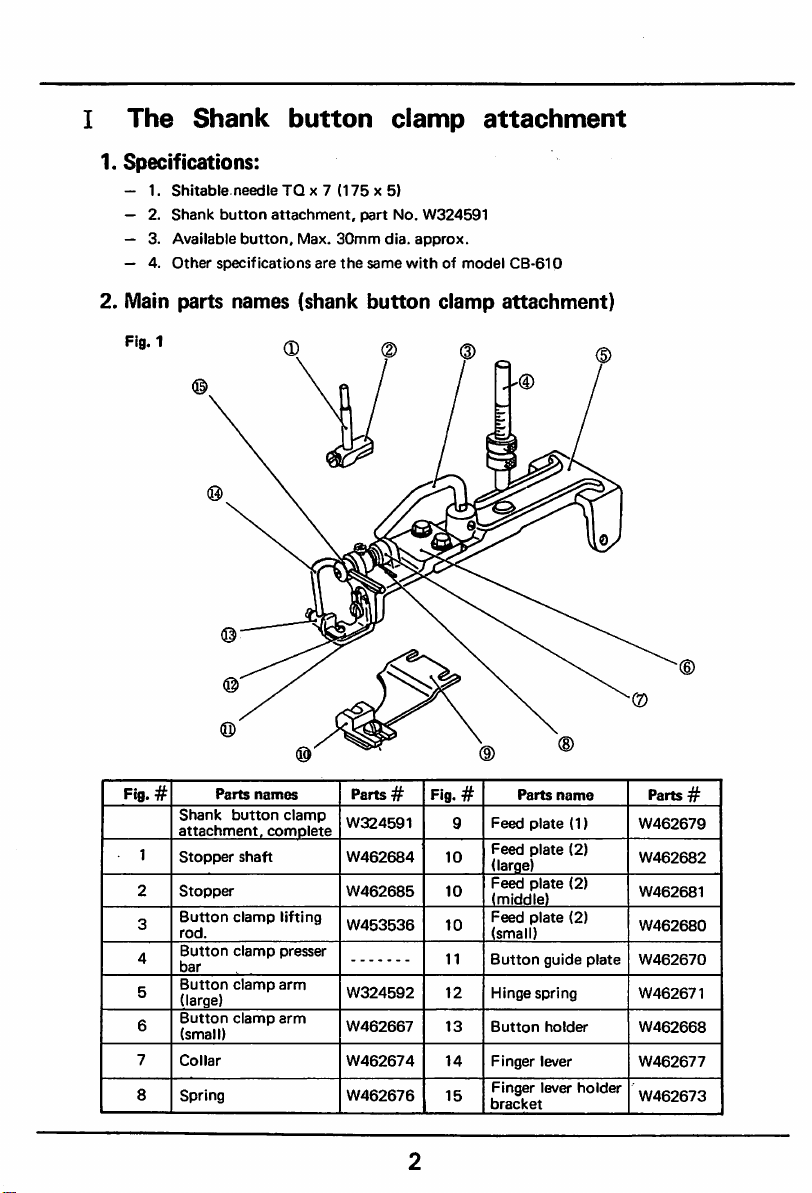
I
The
1.
Specifications:
— 1.
— 2.
— 3.
— 4.
Shank
Shitabte.needle
Shank
button
Available
Other
button.
specifications
button
TQ
x 7
attachment,
Max.
are
(175x5)
part
30mm
the
same
clamp
No.
W324591
dia.
approx.
withofmodel
attachment
CB-610
2. Main parts names (shank
Fig.i Q
©
Fig. #
1
2
3
4
5
6
7
8
Parts
Shank
attachment,
Stopper
Stopper
Button
rod.
Button
bar
Button
(large)
Button
(small)
Collar
Spring
names
button
shaft
clamp
clamp
clamp
clamp
clamp
complete
lifting
presser
arm
arm
button
Parts
W324591
W462684
W462685
W453536
W324592
W462667
W462674
W462676
clamp
#
Fig.#
9
10
10
10
11
12
13
14
15
attachment)
Parts
name
Feed
plate
(1)
Feed
plate
plate
plate
guide
spring
holder
lever
lever
(2)
(2)
(2)
(large)
Feed
(middle)
Feed
(small)
Button
Hinge
Button
Finger
Finger
bracket
plate
holder
Parts #
W462679
W462682
W462681
W462680
W462670
W462671
W462668
W462677
W462673
Page 4
\
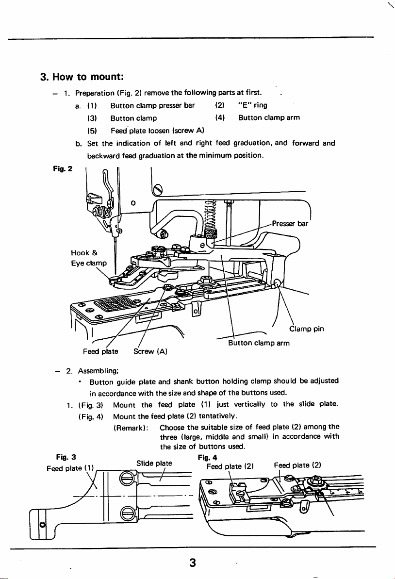
3.
How
to
mount:
Preparation (Fig. 2) remove
- 1.
a. (1)
(3)
Button
Button
clamp
clamp
the
following parts at first,
presser bar (2)
(4)
"E"
Button
ring
clamp
arm
(5) Feed plate loosen (screw A)
Set
the
Fig.
2
Hook
Eye
b.
backward
clamp
indicationofleft
&
feed
graduationatthe
and
right
feed
minimum
graduation,
position.
and
Presser
forward
bar
and
Clamp
Button
clamp
arm
— 2.
Feed
plate
Assembling;
Screw
(A)
• Button guide plate and shank button holding clamp should be adjusted
in
accordance
(Fig.3) Mount the feed plate (1) just vertically to the slide plate.
1.
with
the
size
and
shapeofthe
buttons
used.
(Fig. 4) Mount the feed plate (2) tentatively.
Feed
Fig.
3
plate
(Remark): Choose
(1)
Slide
plate
the
suitable size of feed plate (2)
three (large, middle
the
sizeofbuttons
Fig.
4
Feed
and
used.
plate
small) in
(2)
accordance
Feed
plate
pin
among
(2)
the
with
Page 5
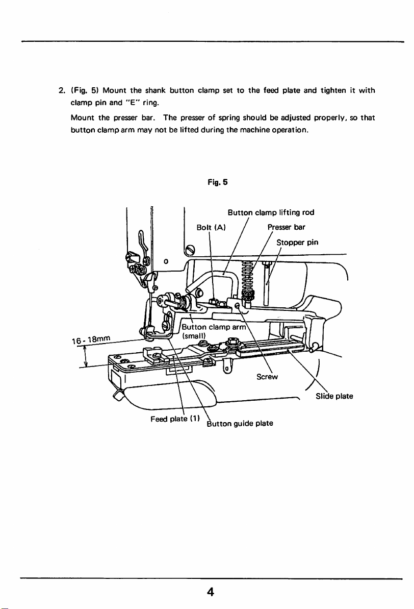
2. (Fig. 5)
clamp
Mount
button
16-
iSmhi
Mount
pin
the
clamp
and
presser
arm
the
"E"
shank
ring.
bar.
may
notbelifted
button
The
presserofspring
Bolt
8
Button
(small)
clamp
during
Fig. 5
clamp
settothe
shouldbeadjusted
the
machine
Button
(A)
/
arm
feed
clamp
Screw
plate
operation.
lifting
Presser
Stopper
and
tightenitwith
properly,sothat
rod
bar
pin
s
Feed
plate
(1)
Button
guide
plate
Slide
plate
Page 6
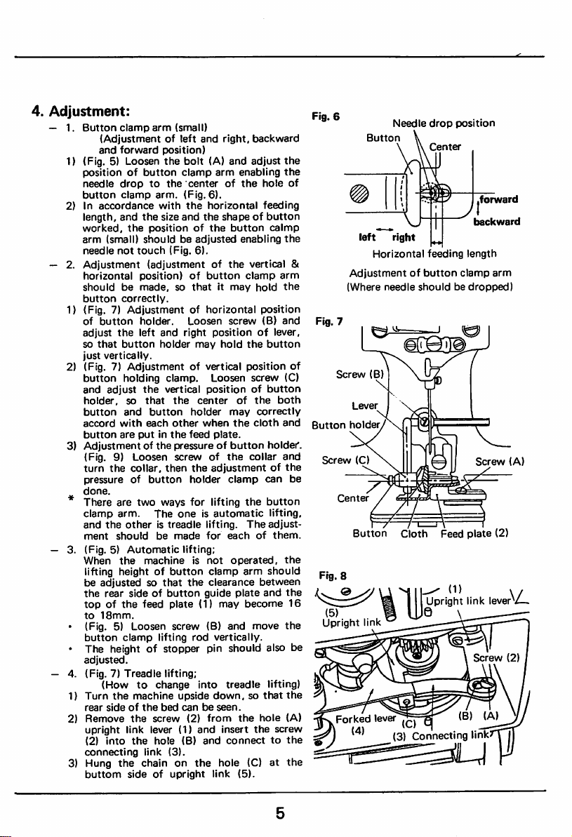
4.
Adjustment:
— 1.
Button
clamp
arm
(Adjustmentofleft
and
1) (Fig. 5) Loosen
2) In
— 2.
1) (Fig. 7)
2) (Fig. 7)
3)
forward
positionofbutton
needle
droptothe
button
clamp
accordance
length, and
worked,
arm
needle
Adjustment
horizontal
shouldbemade,sothatitmay
button
(small)
not
correctly.
the
Adjustmentofhorizontal
of
button
adjust
the
so
that
button
just
vertically.
button
and
holder,
button
accord
button
Adjustmentofthe
(Fig. 9)
turn
pressureofbutton
done.
Adjustment
holding clamp. Loosen
adjust
so
and
with
are
Loosen
the
collar,
• There are two
clamp
arm.
and
the
ment
— 3. (Fig. 5)
When
lifting
be
the
topofthe
to
• (Fig. 5) Loosen screw (B) and
button
• The height of stopper pin should also be
adjusted.
— 4. (Fig. 7)
1)
Turn
rear
2)
connecting
3) Hung
otheristreadle
should
Automatic
the
heightofbutton
adjustedsothat
rear
sideofbutton
18mm.
clamp
Treadle
(Howtochange
the
machine
sideofthe
Remove
upright
(2)
buttom
the
link lever (1)
into
the
the
sideofupright
(small)
and
position)
the
bolt
(A)
clamp
arm
centerofthe
arm.
(Fig.
the
and
(Fig. 6).
Loosen
right
6).
horizontal
the
positionoflever,
may
with
the
size
positionofthe
shouldbeadjusted
touch
(adjustmentofthe
position)ofbutton
holder.
left
and
holder
of vertical
the
vertical
that
button
each
putinthe
ways
The
be
machineisnot
feed
lifting
bed
screw
hole
link
chainonthe
positionofbutton
the
center
holder
other
when
feed
plate.
pressureofbutton
screwofthe
then
the
adjustmentofthe
holder
for
lifting
oneisautomatic
lifting.
made
for
lifting;
clamp
the
clearance
guide
plate
(1)
rod
vertically.
lifting;
into
upside
down,sothat
canbeseen.
(2)
from
and
(B)
and
(3).
link
right,
backward
and
adjust
enabling
hole
feeding
shapeofbutton
button
caimp
enabling
vertical &
clamp
arm
hold
position
screw
(B)
hold
the
button
position
screw
of
the
correctly
cloth
holder.
collar
can
both
may
the
clamp
the button
lifting,
The
adjust
eachofthem.
operated,
arm
should
between
plate
may
hole
and
become
move
treadle
lifting)
the
hole
insert
the
(C)atthe
(5).
screw
connecttothe
the
the
the
the
and
(C)
and
and
the
the
the
the
(A)
of
16
of
be
Fig.
6
left
Adjustmentofbutton
(Where
Fig. 7
Screw
Button
holdeiy\.-(vt
Screw
(C)
Center
Button
(5)
Upright
link
Forked
Needle
Button
right
Horizontal
needle
shouldbedropped)
(B)
Cloth
0 \
lever
(3) Connecting link
drop
r)osition
feeding
length
clamp
Feed
plate
Upright
link
(B)
,forward
backward
arm
Screw
(2)
lever^/-
Screw
(A)
(A)
(2)
Page 7

(2) Stopper should be mounted so that you can take out the button from the lever
opened at the same time when the thread is cut by the treadle lifting.
(Fig. 9) Mount the stopper shaft to the arm with screw (A).
•
Mount
the
Fig.
stoppertothe
• (Fig. 11)
button
position).
9
The
holder to
position of
open
stopper
when
the
the
Screw
shaft.
stopper
button
(Al
shouldbeadjusted
enabling
clamp arm is lifted (stopped
Fig.
10
Screw
finger
Button
Screw
(B)
N
lever
holde^
(C)
Needle
bar
button
bushing
Lever
holder
Screw
(A)
Fig.
11
Lever
Button
—Stopper
cn»
stopper
shaft
Collar
Stopper
Stopper
Screw
shaft
(A)
Button
— 4.
Adjustmentofthe
• TQ X 7 (long
^
needle
bar
height
side
needle)
• (Fig. 9) The timing of the needle bar should be adjusted by means of
indication
of
two
line
(B).
Page 8

01AI3IAI
Page 9

II
The
wrapped-around
button
attachment
1. Nameofthe
main parts (wrapped-around
Fig. 1.
button
attachment).
(1)
Thumbscrew
(4)
Adjustable
plate
(2)
(5)
Adopter
Guide
plate
(3)
(6)
8
Screw
Feed
plate
Page 10

2. How to sew
the
wrapped-around button, and how to mount
the
attachment.
1) Asshown in
between
the
Fig.
2, sew the button by means of makingsome gap
button
and
the
fabric.
Fig. 2.
Button
s
-zzzzzzzz
Fabric
/
v//////.
"A"
Mount
the
between
attachmentinthe
the
fabric
and
following way in
button.
ordertomake
some
gap
Page 11

a) Mount the adopter to the standard flat button clamp with screw (A),
as
shown
in Fig. 3.
Fig. 3.
Thumb
screw
A
Adopter
10
Page 12

2) Do
wrap-around
* In
ordertowrap-around
attachmentinthe
the
button.
following
the
button,
way;
mount
the
wrapped-around
button
a) Remove
3. Button clamp pin. 4. Button clamp attachment complete.
the
following parts (Fig. 4).
1. Button clamp presser bar. 2. E ring.
5. Feed plate (loose screw
"A").
Fig. 4
Presser
bar
Button
clamp
Button
clamp
holder
Feed
plate
Screw
(A)
11
pin
Page 13

b) Mount
* Mount
the screw
the
wrapped-around
the
attachment just vertically to
"A"
as shown in Fig. 5.
Screw
button
Fig. 5.
A
attachment.
the
Slide
plate
slide plate with
Wrapped-around
attachment
button
12
Page 14

3.
Adjustment:
1)
Adjustmentofthe
needle bar height.
a. Use the longer type needle (TQ x 7).
b. Adjust
the
height of
the
needle bar by means of refering
the two timing marks (B) indicated on the needle bar
as
shown
in Fig. 6.
Fig.
6.
Needle
bar
bushing
WrapiDed-around
attachment
button
13
Page 15

2)
Adjustmentofthe
In case of wrapping-around
and
backward
forward
feeding at
"0".
and
the
backward
button,
feeding:
adjust
the
forward
3) Adjust the gap (A) between the adjustable plate and the guide plate
with
the
screw
(B), so
is sewn allowing
the
that
the
proper
gap between fabric
button,
which
with
adopter,
can be tightly inserted as shown in Fig. 7.
Fig. 7.
Screw
Screw
(B)
Button-
Fabric
Needle
right&left
drop
Forward
Adjustable
Guide
Feed
14
(C|
and
plate
length
backward
plate
Page 16

4) Adjustment of the forward and backward position.
Adjust
the
the position of
button
and
needle
the
fabricasshown
enabling
in Fig. 7.
to drop to the center
Adjustment of the gap (A) between the adjustable plate and guide plate,
and
the
forward
and
backward
position
can be done by means of losseningthe screw (B) at the same time
between
5) Adjustment if
Adjust
so
that
sewn
the
6) Adjust
tobesewn,sothat
the
left and right position.
the
position of needle by loosening the screw (C),
needle drops properly on
buttonasshown
the
left and right feed length in accordance with
the
in Fig. 7.
needle
side of the button sewing thread (Fig. 7).
the
both sides of thread
dropsonthe
outer
the
button
15
Page 17

MEMO
16
Page 18

©
'''
•"
••
V,"'•??
^
jj-
"'f
V •-'- ' .
--
^
A
MITSUBISHI
No.
2-3
2-CHOME
ELECTRIC
MARUNOUCHI
CORPORATION
CHIYOOA-KU
TOKYO
'W
JAPAN
"
Js
rs
'4;t
 Loading...