

Mitsubishi Electric A1SJ71PB96F, AJ71PB96F User Manual

MEL SEC A se ries
Pro gram ma ble Con trol ler
User's Ma nu al
Profibus Modules
A(1S)J71PB96F
981001
65629-C
MITSU BIS HI ELECTRIC
MITSU BIS HI ELECTRIC EU RO PE B.V.
FAC TO RY AU TO MA TION

SAFETY PRECAUTIONS
(Read these precautions before using.)
When using Mitsubishi equipment, thoroughly read this manual and the associated manuals
introduced in this manual. Also pay careful attention to safety and handle the module properly.
These precautions apply only to Mitsubishi equipment. Refer to the CPU module user’s manual for a
description of the PC system safety precautions.
These SAFETY PRECAUTIONS classify the safety precautions into two categories: “DANGER”
and “CAUTION”.
DANGER
Procedures which may lead to a dangerous condition and cause death or
serious injury if not carried out properly.
CAUTION
Procedures which may lead to a dangerous condition and cause superficial
to medium injury, or physical damage only, if not carried out properly.
Depending on circumstances, procedures indicated by
CAUTION
may also be linked to serious
results.
In any case, it is important to follow the directions for usage.
Store this manual in a safe place so that you can take it out and read it whenever necessary. Always
forward it to the end user.
[DESIGN PRECAUTIONS]
DANGER
When controlling a PLC by connecting to another station via PROFIBUS for the purpose of changing the
data, changing the program, or changing operation status (status control), an interlock circuit must be
configured in the sequence program so that the entire system will always operate safely.
If a remote PLC is a controlled in the manner indicated above by another station, the system may fail to
respond immediately even if trouble occurs at the remote PLC due to data communication error.
In addition to configuring the interlock circuit in the sequence program, determine the action to be taken by
the system at the occurrence of the data communication error with regard to the processing between the
other stations and PLC CPU.
CAUTION
When the PROFIBUS cable is laid, do not lay it close to main circuits or power lines.
They should be installed 100mm(3.9inch) or more from each other.
Not doing so could result in noise that would cause malfunction.

[INSTALLATION PRECAUTIONS]
CAUTION
Use the module in the environment given in the general specifications of the CPU module’s User’s Manual.
Using the module outside the range of the general specifications may result in electric shock, fire or
malfunction, or may damage or degrade the module.
Insert the tabs at the bottom of the module into the mounting holes in the base unit.
(The AnS series module shall be fastened by screws in the base unit at the specified torque.)
Not installing the module correctly could result in malfunction, breakdowns or pieces of the product falling.
Do not touch the conductive area or electric parts of the module.
Doing so may cause module malfunction or breakdowns.
Tighten the screws with the specified torque. If the screws are loose, it could result in falling, breaks or
malfunction of the module.
If the screws are too tight, it could result in falling, breaks or malfunction due to damage of the screws or the
module.
[WIRING PRECAUTIONS]
CAUTION
Switch all phases of the external power supply of the PC system off before connecting the PROFIBUS cable.
Not doing so could cause failure or malfunction of the module.
Be careful not to let foreign matter such as filings or wire chips get inside the module. These can cause fire,
breakdowns and malfunction.
The PROFIBUS cable which is connected to the module must be protected with a duct or secured in position
with clamps.
Unless the cable is thus protected or secured, the module or the cable could be damaged when the cable
swings, moves or it is strained with careless pulls, or it could cause malfunction when the cable contacts with
any undesirable objects.
When disconnecting the PROFIBUS cable from the module, do not pull by holding the cable section. To
disconnect the cable, make sure to hold the connector which is coupled with the module. Do not attempt to
pull the cable to disconnect it from the module. It could damage the module or the cable, or cause
malfunction due to a poor contact of the cable.
[STARTING AND MAINTENANCE PRECAUTIONS]
DANGER
Switch all phases of the external power supply off before cleaning. Not doing so could cause electric shock.

CAUTION
Never disassemble or modify the module.
This may cause breakdowns, malfunction, injury and/or fire.
Switch all phases of the external power supply off before mounting or removing the module. If you do not
switch off the external power supply, it will cause breakdowns or malfunction of the module.
[OPERATING PRECAUTIONS]
DANGER
Do not write data into the "unused area" of the buffer memory of this modules. Also, do not output the
"unused" signal as the output signal to this module from the PC CPU. Writing data into the "unused area" or
outputting an "unused" signal may cause system malfunctions in the PC.
CAUTION
The online operations conducted for the CPU module being operated (especially when changing data or
operation status), shall be conducted after the manual has been carefully read and a sufficient check of
safety has been conducted.
Operation mistakes could cause breakdowns to or malfunction of the module.
[DISPOSAL PRECAUTIONS]
CAUTION
When disposing of this product, treat it as industrial waste.

Revisions
* The manual number is noted at the lower left of the back cover.
Print Date *Manual Number Revision
Mar. 1997 IB (NA)-66771-A First printing
Jul., 1997
IB(NA)-66771-B
Correction
SAFETY PRECAUTIONS, Section 4.2, 4.4.1, 4.6, 4.7.1, 4.7.2, 6.5, 7.1.12,
7.2.9, 7.2.10, 8.2.1(1)
Addition
Section 4.8(3)
Oct., 1998
IB(NA)-66771-C
Model addition
AJ71PB96F
Correction
SAFTY PRECAUTIONS, Chapter 1, 2, 3, Section 4.1, 4.2, 4.3, 4.5.1, 4.5.3,
4.6, 4.7, 4.8, Chapter 5, Section 6.2, 6.7, 6.11, 6.12, 7.1.1, 7.1.2, 7.1.4,
7.1.5, 7.1.6, 7.1.7, 7.1.8, 7.1.9, 7.1.10, 7.1.11, 7.1.12, 7.1.13, 7.1.14, 7.1.15,
7.1.16, 7.1.17, 7.1.18, 7.1.19, 7.1.20, 7.1.21, 7.1.22, 7.1.23, 7.1.24, 7.2,
Chapter 8, Appendix 1
Addition
Appendix 2, Appendix 5
Chapter alteration
Appendix 2 → Appendix 3,
Appendix 3 → Appendix 4,
Appendix 4 → Appendix 6
This manual does not imply guarantee or implementation right for industrial ownership or implementation
of other rights. Mitsubishi Electric Corporation is not responsible for industrial ownership problems caused
by use of the contents of this manual.
1998 Mitsubishi Electric Corporation

Introduction
Thank you for purchasing the Mitsubishi Programmable Controller MELSEC-A Series.
Before using the equipment, please read this manual carefully to develop full familiarity with the functions
and performance of the graphic operation terminal you have purchased, so as to ensure correct use.
Please forward a copy of this manual to the end user.
Table of Contents
About This Manual
1. OVERVIEW 1-1 to 1-2
1.1 Software Configuration .......................................................................................................................................1- 1
1.2 AJ71PB96F/A1SJ71PB96F Characteristics.......................................................................................................1- 2
2. SYSTEM CONFIGURATION 2-1 to 2-10
2.1 Whole System Configuration..............................................................................................................................2- 1
2.2 Applicable CPU Modules....................................................................................................................................2- 3
2.3 System Configuration Precaution Items .............................................................................................................2- 4
2.3.1 Installable base units...............................................................................................................................2- 4
2.3.2 Combining with the MELSECNET (II), MELSECNET/B, or MELSECNET/10.........................................2- 5
3. SPECIFICATIONS 3-1 to 3-4
3.1 General Specification..........................................................................................................................................3- 1
3.2 Performance Specifications................................................................................................................................3- 2
3.3 Installation Specifications ...................................................................................................................................3- 4
4. FUNCTIONS 4-1 to 4-25
4.1 Positioning in The PROFIBUS-FMS Network.....................................................................................................4- 1
4.2 Bus Parameters..................................................................................................................................................4- 1
4.3 Communication Relationship..............................................................................................................................4- 2
4.3.1 CRL Setting Items and Default Values....................................................................................................4- 3
4.4 Support Service ..................................................................................................................................................4- 6
4.4.1 FMS remote service ................................................................................................................................4- 6
4.4.2 FMA7 remote service ..............................................................................................................................4- 9
4.5 Object Dictionary (OD)........................................................................................................................................4-10
4.5.1 Local OD 4- ............................................................................................................................................10
4.5.2 Local OD default setting..........................................................................................................................4-14
4.5.3 Remote OD..............................................................................................................................................4-15
4.6 I/O Signal List......................................................................................................................................................4-17
4.7 Buffer Memory ....................................................................................................................................................4-19
4.7.1 Information area explanation...................................................................................................................4-20
4.7.2 Network trouble information area............................................................................................................4-21
4.8 Timing Chart .......................................................................................................................................................4-23
5. PROCEDURES BEFORE SYSTEM OPERATION 5-1 to 5-10
5.1 Procedures before Operation .............................................................................................................................5- 1
5.2 Handling Precautions..........................................................................................................................................5- 3
5.3 Part Names and Settings....................................................................................................................................5- 4
5.4 Self-diagnosis Execution Method .......................................................................................................................5- 6
5.5 Wiring ................................................................................................................................................................5- 7

5.5.1 PROFIBUS Cable Wiring.........................................................................................................................5- 7
5.5.2 Terminal switch........................................................................................................................................5- 7
5.5.3 Precautions Against Wiring .....................................................................................................................5- 8
5.6 Maintenance and Inspection...............................................................................................................................5-10
6. COMMUNICATIONS THAT REQUIRE THE SEQUENCE PROGRAM 6-1 to 6-23
6.1 FMS Service and Command No.........................................................................................................................6- 1
6.2 Program Example...............................................................................................................................................6- 1
6.2.1 Write ........................................................................................................................................................6- 1
6.2.2 Information Report...................................................................................................................................6- 2
6.3 FMS Communication Circuit Initiate With Partner Station (Initiate: Initiator)......................................................6- 2
6.4 FMS Communication Circuit Abort With Partner Station (Abort: Requester) .....................................................6- 4
6.5 Partner Station Status Read (Status: Client)......................................................................................................6- 5
6.6 Partner Station Identification Information Read (Identify: Client)........................................................................6- 6
6.7 Partner Station Variable Read (Read: Client).....................................................................................................6- 7
6.8 Partner Station Variable Write (Write: Client).....................................................................................................6-13
6.9 PC CPU Variable Report (Information Report: Requester)................................................................................6-15
6.10 PC CPU Status Report (Unsolicited Status: Requester) ....................................................................................6-17
6.11 Reporting the Partner Station Variable Data to the PC CPU (Information Report: Receiver)............................6-18
6.12 Reports to the Partner Station Status PC CPU (Unsolicited Status: Receiver)..................................................6-22
6.13 FMA7 Connection Abort (FMA7 Abort: Receiver)...............................................................................................6-23
7. COMMUNICATION THAT DO NOT REQUIRE THE SEQUENCE PROGRAM 7-1 to 7-38
7.1 FMS Service .......................................................................................................................................................7- 1
7.1.1 Connection with AJ71PB96F/A1SJ71PB96F (Initiate: Responder)........................................................7- 1
7.1.2 AJ71PB96F/A1SJ71PB96F connection abort (Abort: Receiver).............................................................7- 5
7.1.3 Service reject (Reject).............................................................................................................................7- 6
7.1.4 PC CPU status information (Status: Server)...........................................................................................7- 7
7.1.5 AJ71PB96F/A1SJ71PB96F identification information (Identify: Server).................................................7- 8
7.1.6 Object attribute acquisition (GetOD: Server)...........................................................................................7- 9
7.1.7 Initiate objects attribute setting (InitiatePutOD: Server) ..........................................................................7-11
7.1.8 Object attribute setting (PutOD: Server)..................................................................................................7-13
7.1.9 Object attribute setting termination (TerminatePutOD: Server)...............................................................7-13
7.1.10 Reading device memory and buffer memory (Read: Server)..................................................................7-14
7.1.11 Writing device memory and buffer memory (Write: Server)....................................................................7-15
7.1.12 Reading program capacity and comment capacity, etc. (Read: Server).................................................7-16
7.1.13 Initiating program, parameter, and comment, device buffer memory download
(InitiateDownloadSequence: Server).......................................................................................................7-17
7.1.14 Program, parameter, comment, device and buffer memory downloads
(DownloadSegument: Server).................................................................................................................7-18
7.1.15 Program, parameter, comment, device, and buffer memory download termination
(TerminateDownloadSegument: Server).................................................................................................7-19
7.1.16 Initiating program, parameter, comment, device, and buffer memory upload
(InitiateUploadSequence: Server)...........................................................................................................7-20
7.1.17 Uploading program, parameter, comment, and device buffer memories
(UploadSegument: Server)......................................................................................................................7-21
7.1.18 Termination of upload of program, parameter, comment, and device buffer memories
(TerminateUploadSegument: Server) .....................................................................................................7-22
7.1.19 Execution program definition (Create Program Invocation: Server)........................................................7-23
7.1.20 Execution program delete (Delete Program Invocation: Server).............................................................7-25
7.1.21 Program RUN (Start: Server) ..................................................................................................................7-26
7.1.22 Program pause (Stop: Server).................................................................................................................7-27
7.1.23 Program pause cancel (Resume: Server)...............................................................................................7-28
7.1.24 Program stop (Reset: Server)..................................................................................................................7-29
7.2 FMA7 Service .....................................................................................................................................................7-30
7.2.1 FMA7 communication..............................................................................................................................7-30

7.2.2 FMA7 service outline...............................................................................................................................7-30
7.2.3 FMA7 connection initiation (FMA7 Initiate: Responder)..........................................................................7-31
7.2.4 FMA7 Connection connection abort (FMA7 Abort: Receiver).................................................................7-32
7.2.5 CRL setting initiate (InitiateLoadCRL: Server) ........................................................................................7-33
7.2.6 CRL setting (LoadCRL: Server) ..............................................................................................................7-34
7.2.7 CRL setting end (TerminateLoadCRL: Server).......................................................................................7-34
7.2.8 CRL read (ReadCRL: Server) .................................................................................................................7-35
7.2.9 Bus parameter read (ReadValue: Server)...............................................................................................7-36
7.2.10 Bus parameter setting (SetValue: Server)...............................................................................................7-38
8. TROUBLESHOOTING 8-1 to 8-11
8.1 Troubleshooting..................................................................................................................................................8- 1
8.2 Error Code ..........................................................................................................................................................8- 2
8.2.1 Answer area, receive area.......................................................................................................................8- 2
8.2.2 Communication circuits ...........................................................................................................................8- 8
APPENDIX A-1 to A-12
Appendix 1 Differences From the AJ71PB96............................................................................................................A- 1
Appendix 2 Dissimilarities Between A1SJ71PB96F New Products (Software Version C or Later)
and Conventional Products (Software Version B or Before)..................................................................A- 4
2.1 Dissimilarities Between A1SJ71PB96F New Products (Software Version C or Later)
and Conventional Products (Software Version B or Before)...........................................................A- 4
2.2 Precautionary Notes when Using an A1SJ71PB96F New Product (Software Version C or Later)
and a Conventional Product (Software Version B or Later) Simultaneously...................................A- 6
Appendix 3 VDF Physical Status Criteria Table........................................................................................................A- 7
Appendix 4 DIN 19245 Part 2....................................................................................................................................A- 8
Appendix 5 Maximum Service Counter.....................................................................................................................A-10
Appendix 6 External Dimensions ..............................................................................................................................A-11

About This Manual
The following are manuals related to this product.
Request for the manuals as needed according to the chart below.
Related Manual
Manual Name Manual No.
(Model code)
Type SW0IX-PROFPE Operating Manual IB-66772
(13JL20)
1. OVERVIEW MELSEC-A
1-1
1. OVERVIEW
This manual explains the specifications, handling and communication services for type
AJ71PB96F/A1SJ71PB96F PROFIBUS-FMS interface module (hereafter abbreviated as
AJ71PB96F/A1SJ71PB96F, when explain separately, however, abbreviated as AJ71PB96F,
A1SJ71PB96F.) for connecting the A Series PC to the PROFIBUS-FMS network.
The AJ71PB96F/A1SJ71PB96F operates as the master station in the PROFIBUS-FMS network and
communicates with slave stations or other master stations.
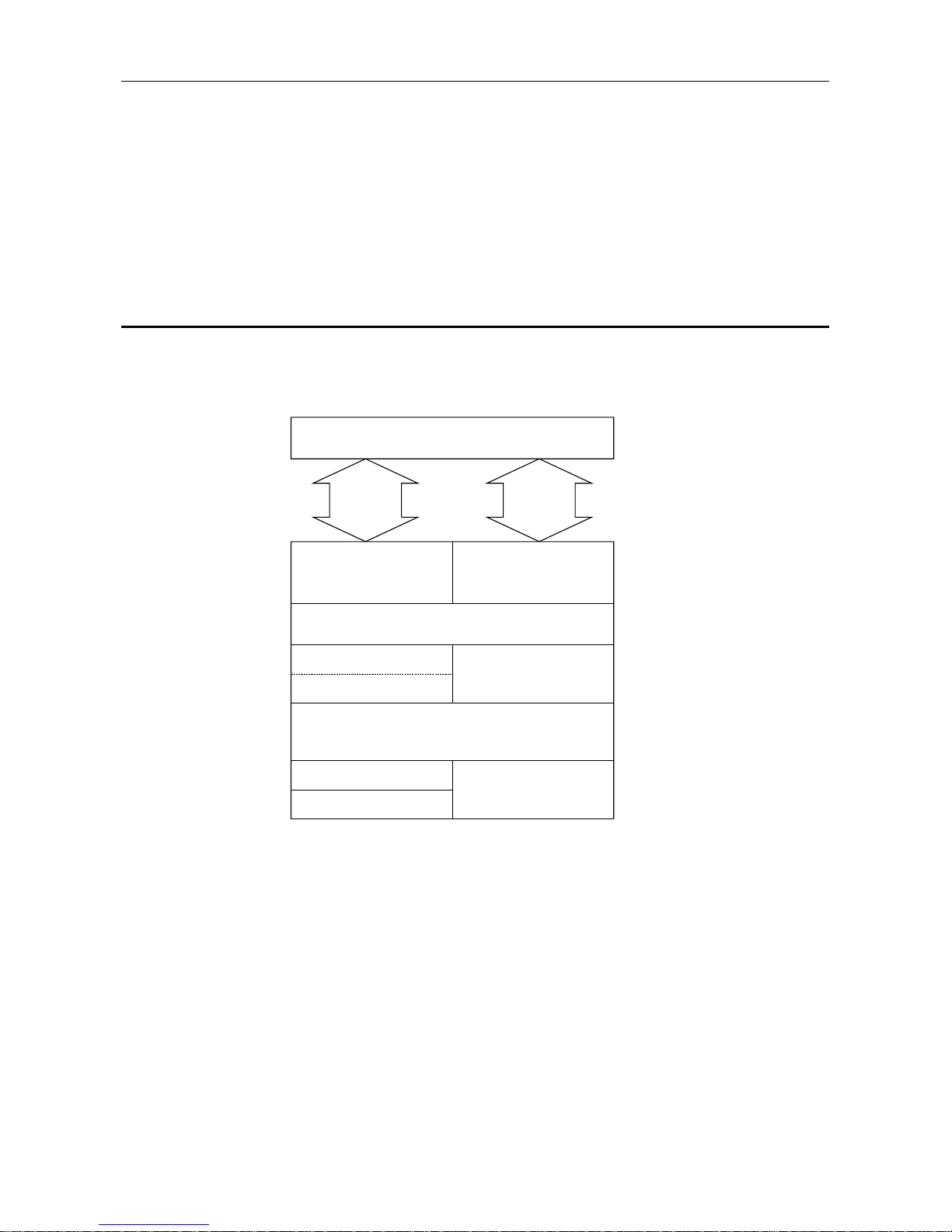
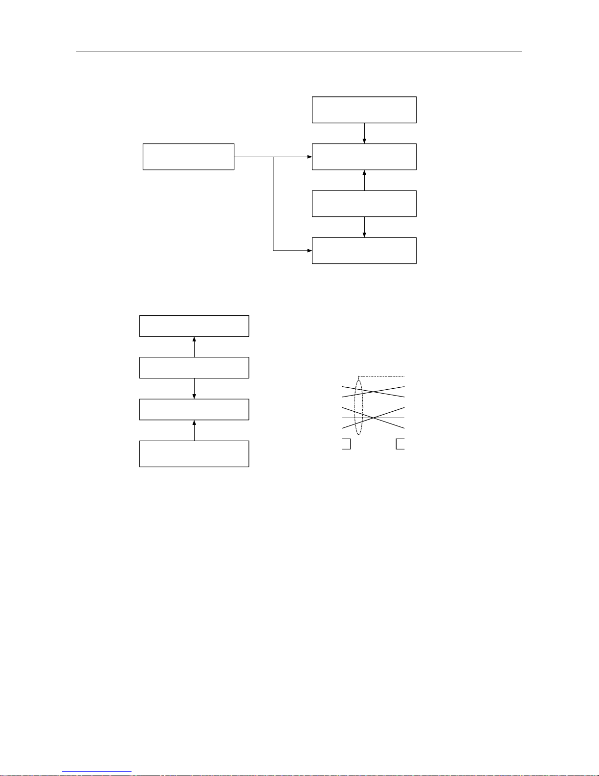
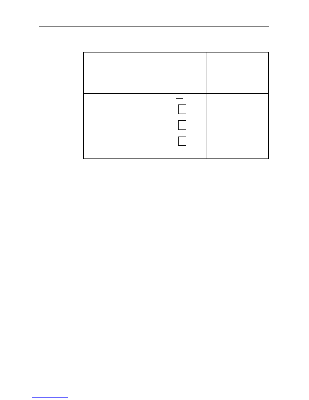
1.1 Software Configuration
The AJ71PB96F/A1SJ71PB96F contains a Physical layer, Datalink layer, Application layer, and VFD
(Virtual Field Device) that comply with PROFIBUS-FMS and conducts data communication with the PC
CPU using a general data interface and buffer memory.
The software configuration is shown in the following diagram.
FROM/TO
VFD
FMS
LL
FDL
PHY
FMA7
empty
FMA1/2
A Series PC
General
data
interface
Communication using
buffer memory
PC CPU device
read/write
communication
7th layer: Application
3rd layer to 6 th layer
2nd layer: Datalink laye
1st layer: Physical layer
Table 1.1 Software configuration
*FMS, LLI, FDL, PHY, FMA7, FMA1/2...PROFIBUS Protocol
1. OVERVIEW MELSEC-A
1-2
1.2 AJ71PB96F/A1SJ71PB96F Characteristics
The AJ71PB96F/A1SJ71PB96F general characteristics are explained below.
(1) Operates as a client or server in the PROFUBUS-FMS network.
(a) When operating as a client:
•
The partner station variable can be read/written using the I/O signal X/Y and buffer
memory.
•
The partner station status and ID information can be read using the I/O signal X/Y and
the buffer memory.
•
The non-confirmation type service can be transmitted using the I/O signal X/Y and the
buffer memory.
(b) When operating as a server:
•
The PC CPU device can be read/written to from the client. (without sequence program)
•
The sequence program, parameters, comments, device memory, and buffer memory can
be uploaded/downloaded from the client. (without sequence program)
•
The sequence program can be run, stopped, or paused from the client. (without
sequence program)
•
The non-confirmation type service can be received using the I/O signal X/Y and the
buffer memory.
The service that can actually be used depends on the connection type and partner station
installed service, etc. For details refer to Item 4-4.
(2) Operates as a master station in the PROFIBUS-FMS network.
In addition, the same operation as that of a slave station can be done using slave
emulation.
(3) When used in combination with MELSECNET (II), MELSECNET/B or MELSECNET/10 the
client can access from the MELSECNET (II), MELSECNET/B or MELSECNET/10 station. For
details refer to Item 2.3.2
(4) The client can read/set the OD (Object Dictionary), CRL (Connection Relationship List), and
bus parameter via the PROFIBUS-FMS network.
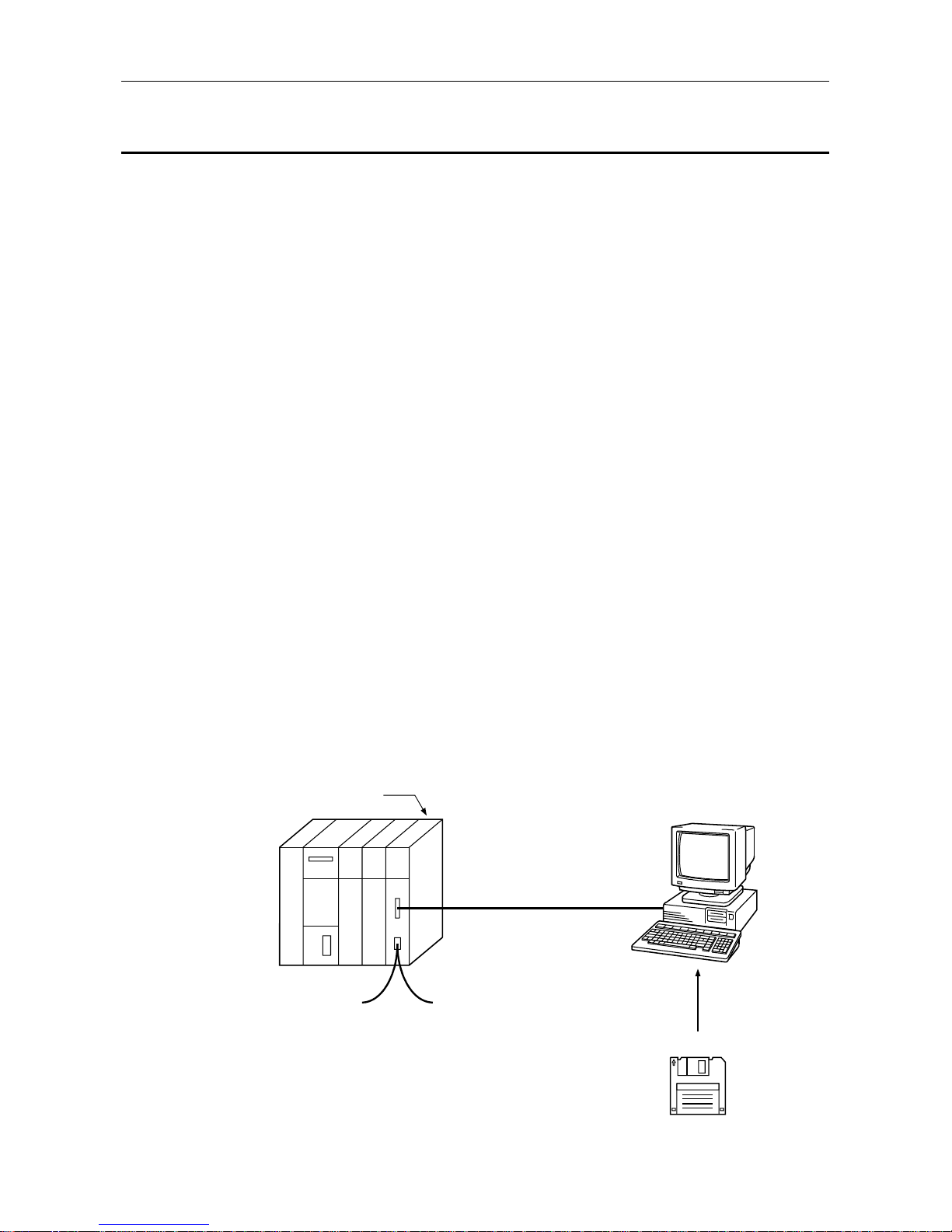
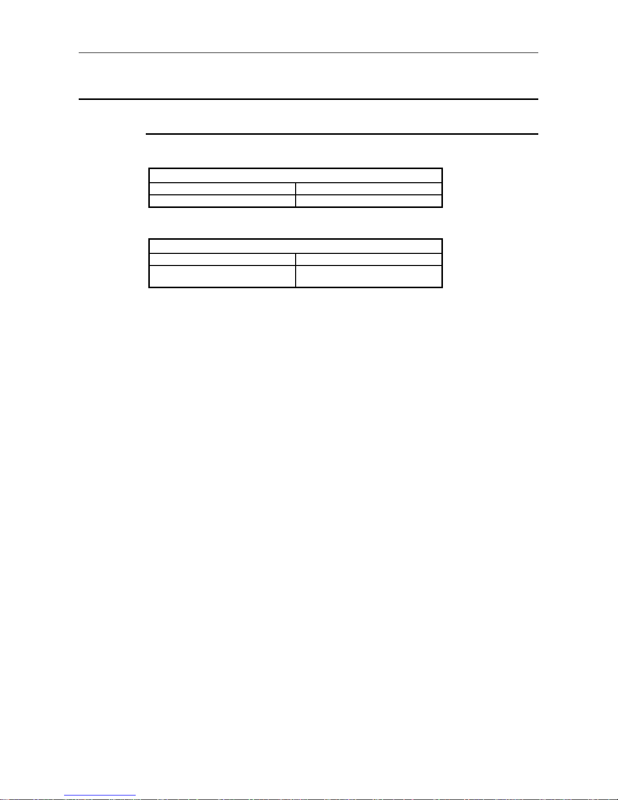
(5) The utility software package SW0IX-PROFPE is used when the OD, CRL, and bus
parameters are set in the AJ71PB96F/A1SJ71PB96F.
SW0IX-PROFPF
RS-232
AJ71PB96F/
A1SJ71PB96F
Operation management terminal
IBM PC/AT or 100% compatible
PROFIBUS-FMS network
Utility Software Package
(Software version B or later)
Table 1.2 System configuration example
2. SYSTEM CONFIGURATION MELSEC-A
2-1
2. SYSTEM CONFIGURATION
This section explains system configuration for the AJ71PB96F/A1SJ71PB96F.
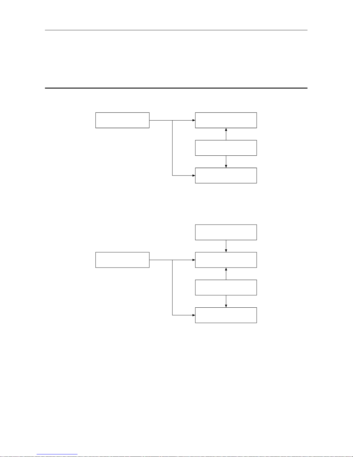
2.1 Whole System Configuration
(1) For the A1SJCPU
A1SJCPU (S3)
Extension cable
Extension base
A1SJ71PB96F
A1SC[ ]B
A1S6[ ]B(S1)/A1S5[ ]B(S1
A1SJHCPU
(2) For the compact building block type CPU
Compact building block type
CPU
Extension cable
A1SC[ ]B
Extension bas
Basic base
A1SJ71PB96F
A1S6[ ]B(S1)/A1S5[ ]B(S1)
A1S3[ ]B/A1S38HB
2. SYSTEM CONFIGURATION MELSEC-A
2-2
(3) For the building block type CPU(A Series)
Building block type CPU
Extension cable
AC[ ]B
Extension bas
Basic base
AJ71PB96
A6[ ]B/A5[ ]B
A3[ ]B/A38HB
(4) Peripheral equipment configuration
AJ71PB96F/
A1SJ71PB96F
Connection cable *1
IBM PC/AT or 100% compatible
Utility software package
SW0IX-PROFPE
1
2
3
4
5
6
7
8
9
1
2
3
4
5
6
7
8
9
DCD
RD
SD
DTR
SG
DSR
RTS
CTS
RI
FG
RD
SD
DTR
SG
DSR
RTS
CTS
RI
IBM PC/AT RS-232
(9 pin)
AJ71PB96F/
A1SJ71PB96F RS-232C
(9 pin)
*1 Provided by the user
Pin assignment
(Software version B or later

2. SYSTEM CONFIGURATION MELSEC-A
2-3
2.2 Applicable CPU Modules
The following table shows the CPUs that the AJ71PB96F/A1SJ71PB96F can use and the number that
can be installed.
(1) AJ71PB96F
Applicable CPU Modules Installable Number Remarks
A1SCPUC24-R2 1 *2
A1SJCPU, A1SJCPU-S3,
A1SCPU, A1SCPU-S1,
A2SCPU, A2SCPU-S1,
A1SJHCPU, A1SHCPU,
A2SHCPU, A2SHCPU-S1,
A1NCPU, A1NCPU P21/R21,
A2NCPU, A2NCPU P21/R21,
A2NCPU-S1, A2NCPU P21/R21-S1,
A3NCPU, A3NCPU P21/R21
2
A2ASCPU, A2ASCPU-S1,
A2ASCPU-S30,
A2ACPU, A2ACPU P21/R21,
A2ACPU-S1, A2ACPU P21/R21-S1,
A3ACPU, A3ACPU P21/R21,
A2UCPU, A2UCPU-S1,
A3UCPU, A4UCPU
6
Q2ASCPU, Q2ASCPU-S1, *1
Q2ASHCPU, Q2ASHCPU-S1
Q2ACPU, Q2ACPU-S1,
Q3ACPU, Q4ACPU, Q4ARCPU
(2) A1SJ71PB96F
Applicable CPU Modules Installable Number Remarks
A1SCPUC24-R2 1 *2
A1SJCPU, A1SJCPU-S3,
A1SCPU, A1SCPU-S1,
A2SCPU, A2SCPU-S1,
A1SJHCPU, A1SHCPU,
A2SHCPU, A2SHCPU-S1
2
A2ASCPU, A2ASCPU-S1,
A2ASCPU-S30
6
Q2ASCPU, Q2ASCPU-S1, *1
Q2ASHCPU, Q2ASHCPU-S1
*1: The accessible range is the A2ACPU/A3ACPU range.
Also, it is impossible to access to the file register R.
*2: When used with the special function modules (including the previous models such as the computer
link module, Ethernet module, etc.) the total installable number of modules will include the number
of these modules used.
•
A1SJ71UC24-R2 (R4/PRF)
•
A1SJ71E71-B2-S3 (-B5-S3)
•
A1SD51S
•
A1SD21-S1
•
A1SJ61BT11: Only during intelligent mode
•
AJ71UC24
•
AJ71E71-S3
•
AD51H-S3
•
AD51-S3
•
AD51FD-S3
•
AD57G-S3
•
A870GOT, A850GOT, A810GOT, A975GOT, A970GOT, A960GOT : Only when connected to bus
•
A851GOT
•
AJ71C21-S1: Only during the basic program mode
•
AD22-S1
•
AJ61BT11: Only during intelligent mode • AJ71C23-S3
However, when the computer link module (A1SJ71UC24-R2, etc.) is used as a multiple drop link
module, there is no limit to the above number of installable modules. Multiple modules can be
installed within the number of I/O points in the PC CPU.
2. SYSTEM CONFIGURATION MELSEC-A
2-4
2.3 System Configuration Precaution Items
2.3.1 Installable base units
The base modules that can be installed in the AJ71PB96F/A1SJ71PB96F are shown below.
(1) AJ71PB96F
Installable Base Units
Basic base unit Extension base unit
A32B, A32B-S1, A35B, A38B, A38HB A52B, A55B, A58B, A62B, A65B, A68B
(2) A1SJ71PB96F
Installable Base Units
Basic base unit Extension base unit *1
A1S32B, A1S33B, A1S35B, A1S38B,
A1S38HB
A1S52B (S1), A1S55B (S1), A1S58B (S1),
A1S65B (S1), A1S68B (S1)
*1: The no power supply module extension base unit A1S5 [ ] B (S1) may not have sufficient power
supply capacity, so use the A1S6 [ ] B (S1) when installing a A1SJ71PB96F in the extension base
unit.
When the A1S5 [ ] B (S1) must be installed, do so after referring to the chapter covering power
supplies in the respective CPU Module User’s Manual.
2. SYSTEM CONFIGURATION MELSEC-A
2-5
2.3.2 Combining with the MELSECNET (II), MELSECNET/B, or
MELSECNET/10
Point
The AJ71PB96F/A1SJ71PB96F cannot be installed in a remote I/O station.
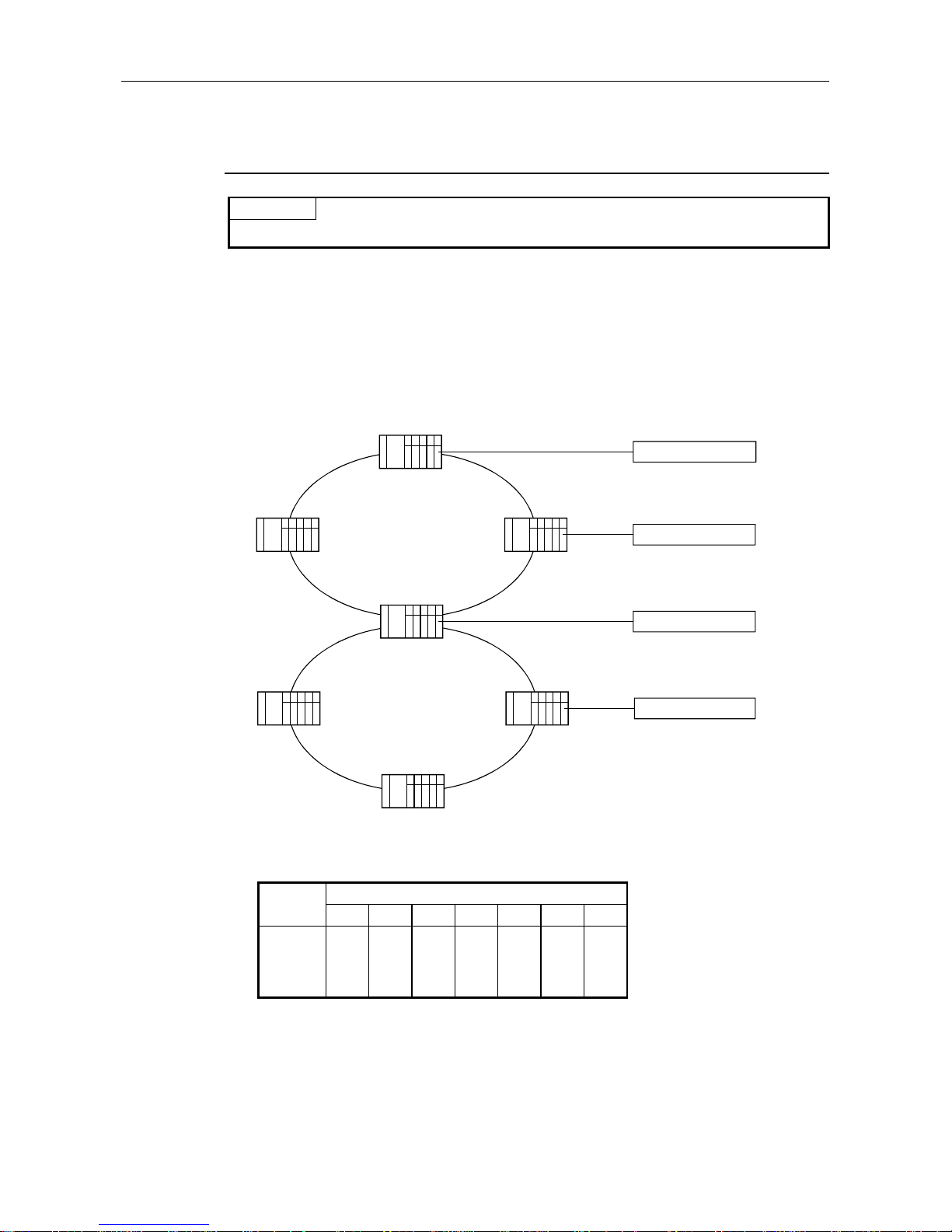
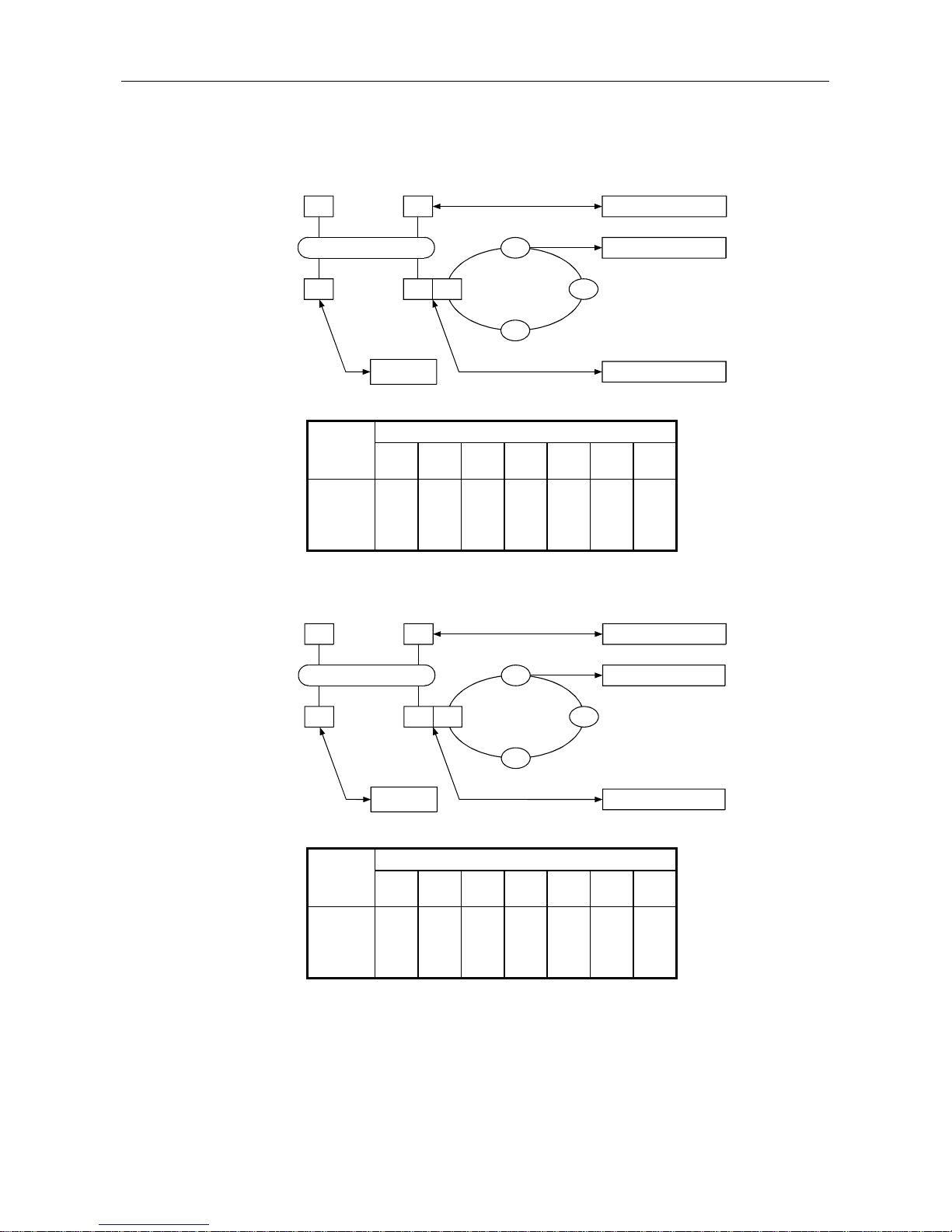
(1) For the MELSECNET (II) or MELSECNET/B
Installing the AJ71PB96F/A1SJ71PB96F in the PC CPU connected to the data link system makes
it possible to read/write the other station PC CPU devices on MELSECNET (II) or MELSECNET/B
from the PROFIBUS other station.
However, PROFIBUS communication requests from the other station PC CPU on the
MELSECNET (II) or MELSECNET/B cannot be transmitted.
In addition, the A0J2CPUP23/R23 or A0J2P25/R25 cannot be accessed.
Master station (M)
Remote 2 station (r2)
Remote
3 station
(R3)
Local
1 station
(L1)
NET (II)
PROFIBUS other station
PROFIBUS other station
PROFIBUS other station
Local 2 station/3rd layer
master station (L2/m)
Local
3 station
(l3)
Local
1 station
(l1)
NET (II)
PROFIBUS other station
Stations that can be installed: Master and local stations. Cannot be installed in the remote I/O
station.
Installable Stations accessible from the PROFIBUS other stations
stations
M L1 L2/m R3 l1 r2 l3
M
×
×
×
L1
× × ×
×
×
L2/m
×
×
l1
× ×
×
×
×
: Access is possible to all devices of the specified CPU.
×
: Access is not possible to the specified CPU.
: Access is possible from the special function module buffer memory.
2. SYSTEM CONFIGURATION MELSEC-A
2-6
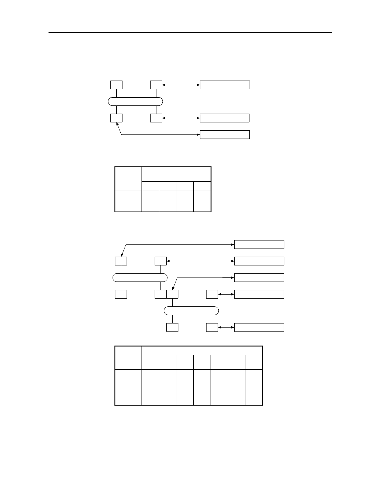
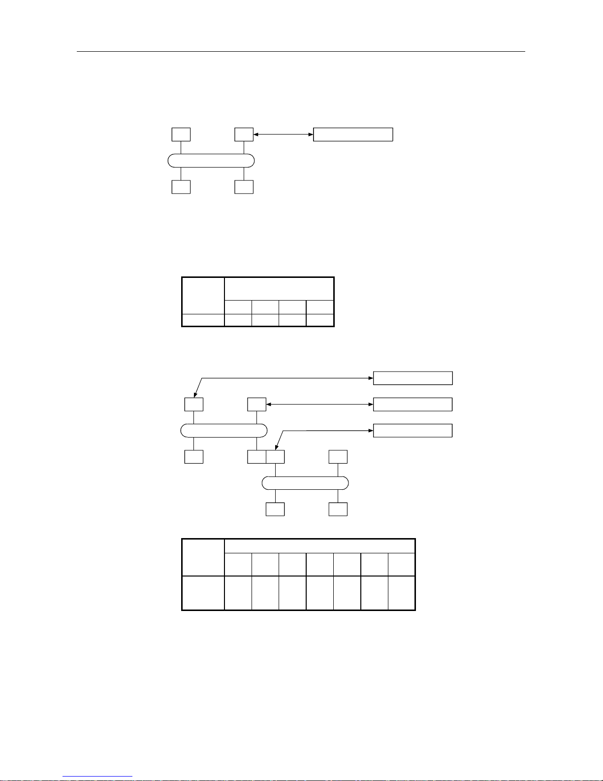
(2) MELSECNET/10 (for networks between PCs)
(a) MELSECNET/10 two-layer system
PROFIBUS other station1Mp1
PROFIBUS other station
PROFIBUS other station
1N3
1Ns2
1Ns4
NET/10 (No.1)
Mp : NET/10 control station
Ns : NET/10 normal station
(AnUCPU, A2ASCPU)
N : NET/10 normal station
(CPU other than
AnU/A2AS)
M : NET (II) master station
L : NET (II) local station
R : Remote station
Stations accessible from the
PROFIBUS other stations
1Mp1 1Ns2 1N3 1Ns4
1Mp1
1N3
×
×
1Ns4
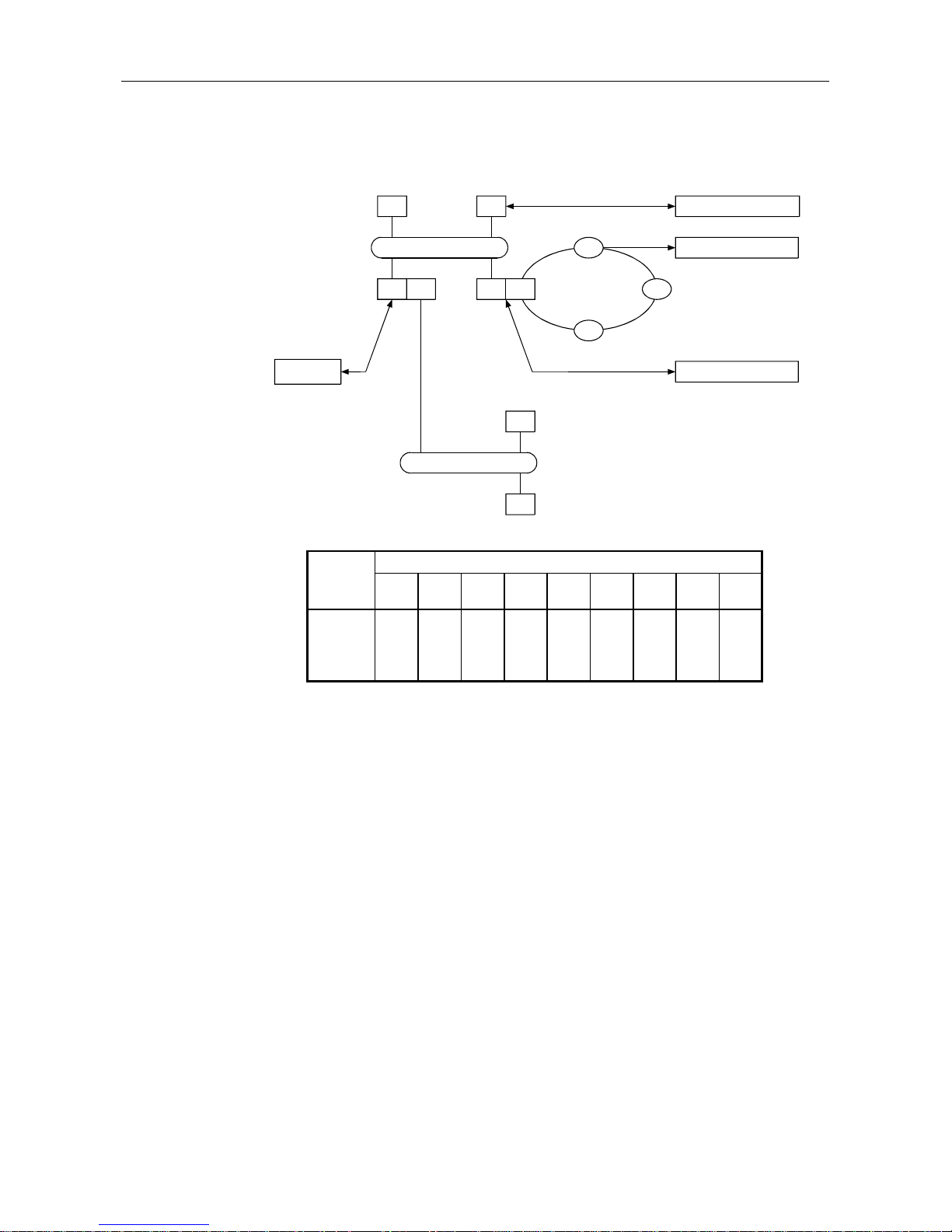
(b) MELSECNET/10 multiple-layer station
PROFIBUS other station
PROFIBUS other station
1Mp11N2
1Ns4
NET/10 (No.1)
PROFIBUS other station
PROFIBUS other station
2N2
PROFIBUS other station
2Ns32Ns4
NET/10 (No.2)
1Ns3 2Mp1
Stations accessible from the PROFIBUS other stations
1Mp1 1N2
1Ns3/
2Mp1
1Ns4 2N2 2Ns3 2Ns4
1Mp1
1N2
×
×
×
×
×
1Ns3/2Mp1
2N2
×
×
×
×
×
2Ns3
Installable
stations
Installable
stations
2. SYSTEM CONFIGURATION MELSEC-A
2-7
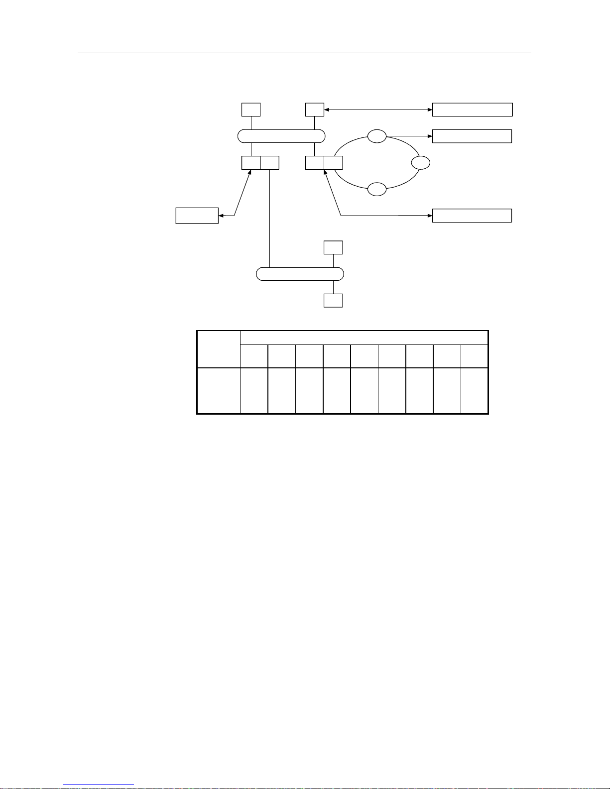
(c) MELSECNET/10 and MELSECNET (II) mixed systems
•
When the intermediate terminal is an AnUCPU/A2ASCPU
PROFIBUS other station1Ns1
1Ns3
1N2
1Mp4
NET/10 (No.1) PROFIBUS other station
PROFIBUS other station
PROFIBUS
other statio
M
L1
L2
R3
NET (II)
Stations accessible from the PROFIBUS other stations
1Ns1 1N2
1Ns3/
M
1Mp4 L1 L2 R3
1Ns1
×
×
×
1Ns3/M
1Mp4
×
×
×
L1
×
×
×
×
×
•
When the intermediate station is other than an AnUCPU/A2ASCPU
PROFIBUS other station1Mp1
1N3
1Ns2
1Ns4
NET/10 (No.1) PROFIBUS other station
PROFIBUS other station
PROFIBUS
other statio
M
L1
L2
R3
NET (II)
Stations accessible from the PROFIBUS other stations
1Mp1 1Ns2
1N3/
M
1Ns4 L1 L2 R3
1Mp1
×
×
×
1N3/M
×
×
1Ns4
×
×
×
L1
×
×
×
×
×
Installable
stations
Installable
stations
2. SYSTEM CONFIGURATION MELSEC-A
2-8
(3) MELSECNET/10 (for remote I/O networks)
(a) MELSECNET/10 two-layer system
PROFIBUS other station1Mr
1R1
1R3
1R2
NET/10 (No.1)
Mp : NET/10 control station
Ns : NET/10 normal station
(AnUCPU, A2ASCPU)
N : NET/10 normal station
(CPU other than
AnU/A2AS)
Mr : NET/10 remote I/O master
M : NET (II) master station
L : NET (II) local station
R : Remote station
Stations accessible from the
PROFIBUS other stations
1Mr 1R1 1R2 1R3
1Mr
(b) MELSECNET/10 multiple-layer system
PROFIBUS other station
PROFIBUS other station
1Mp11N2
1Ns4
NET/10 (No.1
PROFIBUS other station
2R1
2R22R3
NET/10 (No.2
1Ns3 2Mr
Stations accessible from the PROFIBUS other stations
1Mp1 1N2
1Ns3/
2Mr
1Ns4 2R1 2R2 2R3
1Mp1
1N2
×
×
×
×
×
1Ns3/2Mr
Installable
stations
Installable
stations
2. SYSTEM CONFIGURATION MELSEC-A
2-9
(c) MELSECNET/10 and MELSECNET(II) compound system
•
When the intermediate station is an AnUCPU/A2ASCPU
PROFIBUS other station1Ns1
1Ns3
1N2
1Mp4
NET/10 (No.1)
2R1
2R2
NET/10 (No.2)
PROFIBUS other station
PROFIBUS other station
PROFIBUS
other station
M2Mr
L1
L2
R3
NET (II)
Stations accessible from the PROFIBUS other stations
1Ns1 1N2
1Ns3/ M 1Mp4/
2Mr
2R1 2R2 L1 L2 R3
1Ns1
×
×
×
1Ns3/M
1Mp4/2Mr
×
×
×
L1
×
×
×
×
×
×
×
Installable
stations
2. SYSTEM CONFIGURATION MELSEC-A
2-10
•
When the intermediate station is other than the AnUCPU/A2ASCPU
PROFIBUS other station1Ns1
1N3
1N2
1Mp4
NET/10 (No.1)
2R1
2R2
NET/10 (No.2)
PROFIBUS other station
PROFIBUS other station
PROFIBUS
other station
M2Mr
L1
L2
R3
NET (II)
Stations accessible from the PROFIBUS other stations
1Ns1 1N2
1N3/ M 1Mp4/
2Mr
2R1 2R2 L1 L2 R3
1Ns1
×
×
×
1Ns3/M
×
×
×
×
1Mp4/2Mr
×
×
×
L1
×
×
×
×
×
×
×
Installable
stations
3. SPECIFICATIONS MELSEC-A
3-1
3. SPECIFICATIONS
This section explains the AJ71PB96F/A1SJ71PB96F the general specifications, performance
specifications, and transmission specifications.
3.1 General Specification
This section explains the AJ71PB96F/A1SJ71PB96F general specifications.
Table 3.1 General Specification
Item Specifications
Ambient operating
temperature
0 to 55
°
C
Ambient storage temperature -20 to 75°C
Ambient operating humidity 10 to 90%RH, Non-condensing
Ambient storage humidity 10 to 90%RH, Non-condensing
Frequency Acceleration Amplitude No. of sweeps
10 to 57Hz —
0.075mm
(0.003inch)
Vibration resistance 57 to 150Hz 9.8m/s2 {1G} —
10 to 57Hz —
0.035mm
(0.001inch)
57 to 150Hz 4.9m/s2 {0.5G} —
Shock resistance
Conforming to JIS B3501, IEC 1131-2
(147m/s2 {15G}, 3 times in each of 3 directions X Y Z)
Operating ambience No corrosive gases
Operating elevation 2000m (6562 feet) max.
Installation location Control panel
Over voltage category
*
1
II max.
Pollution level
*
2
2 max.
*1: This indicates the section of the power supply to which the equipment is assumed to be
connected between the public electrical power distribution network and the machinery within the
premises. Category II applies to equipment for which electrical power is supplied from fixed
facilities. The surge voltage withstand level for up to the rated voltage of 300V is 2500V.
*2: This index indicates the degree to which conductive material is generated in terms of the
environment in which the equipment is used. Pollution level 2 is when only non-conductive
pollution occurs. A temporary conductivity caused by condensation must be expected
occasionally.
10 times each in
X, Y, Z directions
(for 80 min.)
Conforming to
JIS B3501,
IEC 1131-2
Under intermittent
vibration
Under continuous
vibration
3. SPECIFICATIONS MELSEC-A
3-2
3.2 Performance Specifications
This section explains performance specifications for the AJ71PB96F/A1SJ71PB96F.
Table 3.2 Performance Specifications
Item Specifications
Model AJ71PB96F A1SJ71PB96F
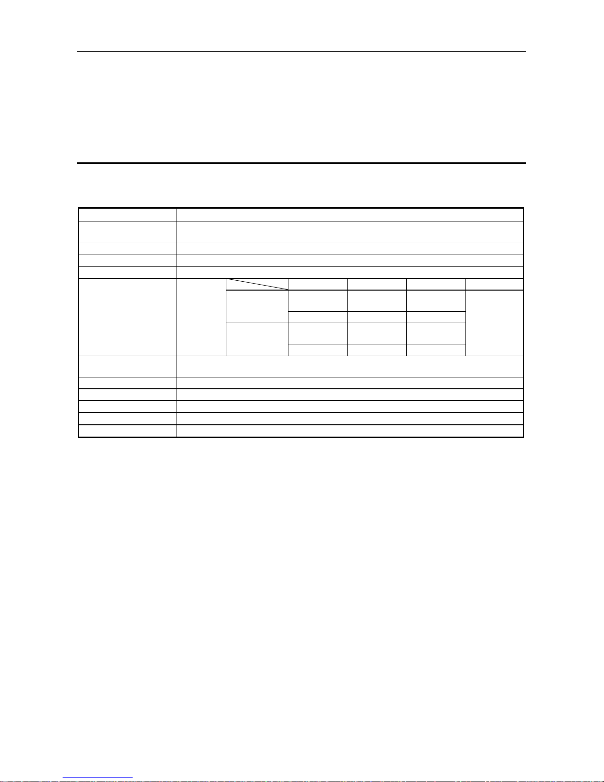
Transmission speed 9.6, 19.2, 93.75, 187.5, 500, 1500kbps
Coding method NRZ
Synchronization method Asynchronous
Electrical standards and characteristics EIA-RS485 compliance
Medium Shield twisted cable
Network configuration (topology) Bus type (However, tree type when a repeater is used)
Transmission
9.6kbps
19.2kbps
93.75kbps
1200m (3937ft.)
distance 187.5kbps 600m (1969ft.)
500kbps 200m (656ft.)
1500kbps 100m (328ft.)
Number of connection nodes 32, 62 (1 repeater), 9 (2 repeaters), 122 (3 repeaters)
Number of repeaters/network *1 3 repeaters (max)
Data link method
Token passing (between master-master), polling (between
master-slave)
Transmittable data 241 bytes (max)/1 time
Number of occupied I/O points 32 points (I/O allocation: special 32 points)
5VDC internal power consumption (A) 0.54 0.56
Withstand noise, withstand voltage,
insulation resistance
According to the power supply module specifications of
the system in which the AJ71PB96F/A1SJ71PB96F will be
installed. (Refer to the CPU module's users manual.)
External dimensions (mm)
250 (9.84in.) (H) ×
37.5 (1.48in.) (W)
×
106 (4.17in.) (D)
130 (5.12in.) (H) ×
34.5 (1.36in.) (W)
×
97.6 (3.84in.) (D)
Weight (kg) 0.37(0.81lb) 0.27 (0.59lb)
*1 The transmission distance (m/network) can be extended by using a repeater.
Transmission distance (m/network) = (number of repeaters + 1) × transmission distance (m/segment)
3. SPECIFICATIONS MELSEC-A
3-3
*2 Transmission line
Items Specifications Remarks
PROFIBUS cable impedance
Capacity
Conductor resistance
Conductor cross section area
Twisted pair cable
100 to 120
Ω
(>100kHz)
<60nF/km
<160
Ω
/km
>0.22mm
2
User distribution
Terminal resistance
390
Ω
150
Ω
390
Ω
VP (6)
RxD/TxD-N (8)
RxD/TxD-P (3)
DGND (5)
Set yes/no by the main module
switch

3. SPECIFICATIONS MELSEC-A
3-4
3.3 Installation Specifications
This section explains installation specifications for the AJ71PB96F/A1SJ71PB96F.
Table 3.3 Installation Specifications
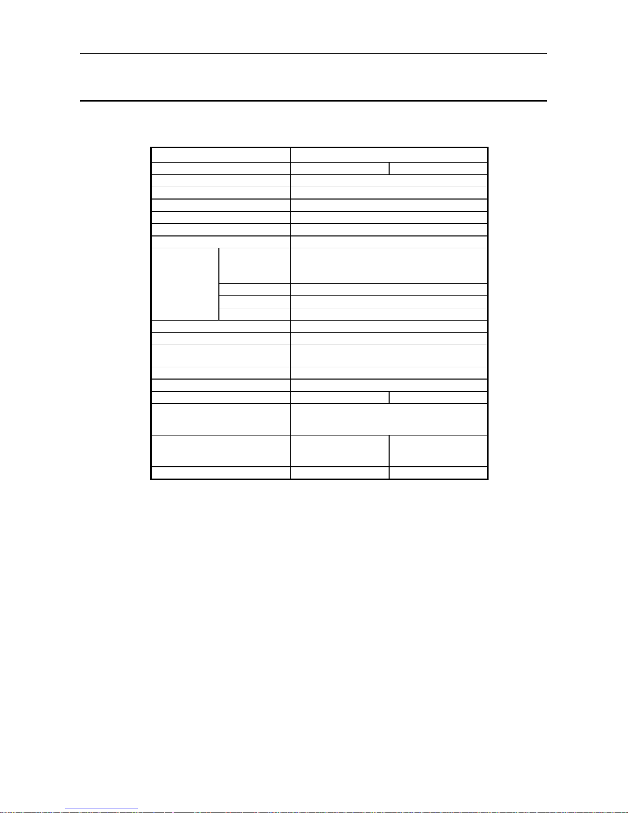
OSI layer name PROFIBUS protocol Compliance standards
Application layer FMS, LLI, FMA7 PROFIBUS proprietary (DIN19245)
Presentation layer
Session layer
Transport layer
Network layer
Data link layer FDL
FMA1/2
PROFIBUS proprietary
(DIN19245)
Physical layer PHY RS-485
PROFIBUS proprietary
(DIN19245)

4. FUNCTIONS MELSEC-A
4-1
4. FUNCTIONS
4.1 Positioning in the PROFIBUS-FMS Network
The AJ71PB96F/A1SJ71PB96F in PROFIBUS-FMS network is positioned to the following.
(1) The AJ71PB96F/A1SJ71PB96F operates as a master station in the PROFIBUS-FMS
network.
(2) The AJ71PB96F/A1SJ71PB96F contains both client and server functions.
4.2 Bus Parameters
The bus parameters are the communication parameters prescribed for the PROFIBUS protocol No. 2
layer operation. Bus parameters are set using the SW0IX-PROFPE.
The bus parameter rangers and default values that can be set in AJ71PB96F/A1SJ71PB96F are
shown below.
Table 4.1 Bus Parameters Setting Items
Item Unit Setting range Default value
Local address 0 to 126 0
Baud rate 9.6, 19.2, 93.75, 187.5, 500, 1500kbps 9.6kbps
Slot time Bit Time 37 to 16383 100
Min Tsdr Bit Time 11 to 1023 30
Max Tsdr Bit Time 37 to 65535 50
Quiet Time Bit Time 0 to 127 22
Setup Time Bit Time 1 to 255 5
Target Rotation Time Bit Time 256 to 16777215 10000
GAP Update Factor 1 to 100 1
Has 1 to 126 126
Max Retry Limit 0 to 7 1
Remark
Following is an explanation of the terminology used for bus parameters.
Tsdr: Station Delay Time as Responder
Bit Time: The time required to transmit 1 bit = 1/baud rate
Slot Time: The maximum time that the requester must wait for a response from the
responder. Max Tsdr < Slot Time
Min Tsdr: The minimum time required for the responder to respond.
Quiet Time < Min Tsdr, Setup Time < Min Tsdr
Max Tsdr: The maximum time required for the responder to respond.
Quiet Time: The time required for the repeater to switch from the transmission mode to the
receive mode.
Setup Time: The time required for the requester to switch from the transmission mode to
the receive mode.
Target Rotation Time: If the actual token rotation time becomes larger than this time, cyclic
communication will no longer be possible.
GAP Update Factor: This shows how many times the station information can be updated for 1 token
rotation.
Station information update interval = G x Target Rotation Time
HSA: Highest Station Address. The highest address of the stations connected to the
network.
Max Retry Limit: The maximum number of transmission retries when data transmission fails.

4. FUNCTIONS MELSEC-A
4-2
4.3 Communication Relationship
In PROFIBUS, all of the connection information must be written in CRL (Communication Relationship
List) as communication relationships (hereafter abbreviated as communication). Communication
contains connection oriented communication that is required for establishing logical circuits before
communication and connection less list communication that does not have data communication
certainty when establishing logical circuits before communication is not required. In addition, it also
contains FMS communication and FMA7 communications.
The following communication types are prescribed for FMS communication.
MMAC (Master to Master Acyclic Connection)
MSAC (Master to Slave Acyclic Connection)
MSAC_SI (Master to Slave Acyclic Connection/Slave Initiative)
MSCY (Master to Slave Cyclic Connection)
MSCY_SI (Master to Slave Cyclic Connection/Slave Initiative)
BRCT (Broadcast)
MULT (Multicast)
In addition, the communications other than BRCT and MULT have the following attributes:
/D : Defined connection
/I : Request open connection
/O : Responder open connection
However, MSxx's /O connections are not allowed. (PROFIBUS standard) Of these, BRCT and
MULT are connectionless communications and the others are connection oriented communications.
All FMA7 communications are connection oriented.
In AJ71PB96F/A1SJ71PB96F, the above all communications are enable to use by using the software
package.
In AJ71PB96F/A1SJ71PB96F, when the following conditions are met the maximum number of
communications including FMA7 communications can be set to 32. In other cases the maximum
number of communications that can be set is 16.
(1) Communication type conditions
Communications are divided into the following two types.
Category I
MMAC (Master to Master Acyclic Connection)
MSAC (Master to Slave Acyclic Connection)
MSCA_SI (Master to Slave Acyclic Connection/Slave Initiative)
SMA7 communication
Category II
MSCY (Master to Slave Cyclic Communication)
MSCY_SI (Master to Slave Cyclic Communication/Slave Initiative)
BRCT (Broadcast)
MULT (Multicast)
The number of communications must satisfy the following formula.
Category I number of communications × 2 + Category II number of communications ≤ 32
(2) PDU size conditions
All of the PDU sizes for all communications shall be 200 or less.

4. FUNCTIONS MELSEC-A
4-3
4.3.1 CRL Setting Items and Default Values
The CRL setting items are shown below. At the time of shipment the default is set to 16 MMAC/O
connections.
Table 4.2 CRL Setting Items
Item Setting range Default value
CREF 1 to 33 2 to 17
Symbol Connection name (32 characters) Connection_01 to
Connection_16
Password 0 to 255 0
Access Group 0 to 255 0
Local LSAP (SSAP) 0 to 60, 63, 128 2 to 17
Remote Address 0 to 127, 255 255 (ALL)
Remote LSAP (DSAP) 0, 2 to 63, 128, 255 255 (ALL)
Connection Type MMAC, MSAC, MSAC_SI, MSCY,
MSCY_SI, BRCT, MULT
MMAC
Connection Attribute /D, /I, /0 /0
Control Interval 0 to 4294967294 4096
Max SCC 0 to 1 1
Max RCC 0 to 2 2
Max SAC 0 to 1 1
Max RAC 0 to 1 1
Max send PDU (H) 0 to 241 241
Max send PDU (L) 0 to 241 241
Max receive PDU (H) 0 to 241 241
Max receive PDU (L) 0 to 241 241
Features Supported 00 00 00 00 00 00 to
FF FF FF FF FF FF
00 30 00 F9 B0 81
The default connection contains the following restriction items.
(1) Connection establishment requests are only output from communication partner stations.
(2) Communication is only possible with stations that do not support access protection.
(3) Only for MMAC.
(4) The only services that can be output by the PC are read and write.
For other cases the setting must be conducted using the SW0IX-PROFPE.

4. FUNCTIONS MELSEC-A
4-4
Remark
Following is an explanation of the terminology used with CRL.
(a) Connection Type
•
MMAC: Master to Master Acyclic Connection. Service requests can be sent from both
stations.
•
MSAC: Master to Slave Acyclic Connection. Service requests can only be sent from the
master station.
•
MSAC_SI: Master to Slave Acyclic Connection. (Service requests can be sent from the
slave station.) In addition to the MSAC communication format InformationReport
and UnsolicitedStatus can be sent from the slave station.
•
MSCY: Master to Slave Cyclic Connection. Service requests can only be sent from the
master station.
•
MSCY_SI: Master to Slave Cyclic Connection: (Service requests can also be made from the
slave station.) In addition to the MSCY communication format InformationReport
and UnsolicitedStatus can be sent from the slave station.
•
BRCT: Broadcast communication (connectionless). InformationReport and
UnsolicitedStatus can be sent from master stations to all stations.
•
MULT: Multicast communication (connectionless). InformationReport and
UnsolicitedStatus can be sent to multiple stations within a certain group.
The group consists of stations with the same Remote LSAP.
(b) Connection Attribute
•
/D: Define Connection. This attribute securely fixes the connection partner.
•
/I: Requester Open Connection. When establishing a connection multiple partner
stations are connected to the LSAP of the receiving side. (However, the
connections are not made at the same time.)
•
/O: Responder Open Connection. When establishing a connection multiple partner
stations are connected to the LSAP of the receiving side. (However, the
connections are not made at the same time.)
(c) Control Interval: This is the monitoring interval during which the communication partner station
to which the connection is established is monitored to see if it is operating
correctly.
(d) Max SCC: Max Send Confirmed request Counter. The number of maximum confirmed
services that can be sent by the confirmed service request side (client) before
the response to the previously sent service is received.
(e) Max RCC: Max Receive Confirmed request Counter. The number of maximum confirmed
services that can be received by the confirmed service request reception side
(server) before the previously sent service is returned.
(f) Max SAC: Max Send Acknowledged request Counter. This is the number of unconfirmed
services that can be sent by the unconfirmed service request sending side
before the ACK of the previously sent service is received.
(g) Max RAC: Max Received Acknowledged request Counter. This is the number of
unconfirmed services that can be received by the unconfirmed services
receiving side before the response to the previously sent service is returned.
(h) Max send PDU(H): This is the maximum size of a packet sent by high priority. Acyclic
communication data is sent by high priority.
 Loading...