

Mitsubishi AA121XN11 Specification
Global LCD Panel Exchange Center
Preliminary
www.panelook.com
TENTATIVE
All information in this technical data sheet is tentative
and subject to change without notice.
12.1” XGA
TECHNICAL SPECIFICATION
Sample Product Name : AA121XN11-CE-01
MITSUBISHI ELECTRIC Corp.
Date: Aug.8,’12
MITSUBISHI Confidential (1/29) AA121XN11-CE-01_02_00
One step solution for LCD / PDP / OLED panel application: Datasheet, inventory and accessory!
www.panelook.com
Global LCD Panel Exchange Center
CONTENTS
No. Item Page
-- COVER 1
-- CONTENTS 2
1 APPLICATION 3
2 OVERVIEW 4
3 ABSOLUTE MAXIMUM RATINGS 5
4 ELECTRICAL CHARACTERISTICS 5, 6, 7, 8
www.panelook.com
5 INTERFACE PIN CONNECTION 9, 10, 11, 12
6 INTERFACE TIMING 13, 14, 15, 16, 17
7 BLOCK DIAGRAM 18
8 MECHANICAL SPECIFICATION 19, 20, 21
9 OPTICAL CHARACTERISTICS 22, 23, 24
10 RELIABILITY TEST CONDITION 25
11 OTHER FEATURE 26
12 HANDLING PRECAUTIONS FOR TFT-LCD MODULE 27, 28, 29
MITSUBISHI Confidential (2/29) AA121XN11-CE-01_02_00
One step solution for LCD / PDP / OLED panel application: Datasheet, inventory and accessory!
www.panelook.com

Global LCD Panel Exchange Center
1. APPLICATION
This specification applies to color TFT-LCD module, AA121XN11-CE-01.
These specification papers are the proprietary product of Mitsubishi Electric Corporation
(“MITSUBISHI) and include materials protected under copyright of MITSUBISHI. No part of this
document may be reproduced in any form or by any means without the express written permission
of MITSUBISHI.
MITSUBISHI does not assume any liability for infringement of patents, copyrights or other
intellectual property rights of third parties by or arising from use of a product specified in this
document. No license, express, implied or otherwise, is granted under any patents, copyrights or
other intellectual property rights of MITSUBISHI or of others.
MITSUBISHI classifies the usage of the TFT-LCD module as follows. Please confirm the usage
before using the product.
www.panelook.com
(1) Standard Usage
Computers, office equipment, factory automation equipment, test and measurement
equipment, communications, transportation equipment(automobiles, ships, trains, etc.),
provided, however, that operation is not influenced by TFT-LCD directly.
(2) Special Usage
Medical equipment, safety equipment, transportation equipment, provided, however, that
TFT-LCD is necessary to its operation.
(3) Specific Usage
Cockpit Equipment, military systems, aerospace equipment, nuclear reactor control
systems, life support systems and any other equipment. MITSUBISHI should make a
contract that stipulate apportionment of responsibilities between MITSUBISHI and our
customer.
The product specified in this document is designed for “Standard Usage” unless otherwise specified
in this document. If customers intend to use the product for applications other than those specified
for “Standard Usage”, they should first contact MITSUBISHI sales representative for it's intended
use in writing.
MITSUBISHI has been making continuous effort to improve the reliability of its products.
Customers should implement sufficient reliability design of their application equipments such as
redundant system design, fail-safe functions, anti-failure features.
MITSUBISHI assumes no responsibility for any damage resulting from the use of the product that
does not comply with the instructions and the precautions specified in this document.
Please contact and consult a MITSUBISHI sales representative for any questions regarding this
product.
MITSUBISHI Confidential (3/29) AA121XN11-CE-01_02_00
One step solution for LCD / PDP / OLED panel application: Datasheet, inventory and accessory!
www.panelook.com
Global LCD Panel Exchange Center
2. OVERVIEW
AA121XN11-CE-01 is 12.1” color TFT-LCD (Thin Film Transistor Liquid Crystal Display) module
composed of LCD panel, driver ICs, control circuit, backlight unit, touch panel, and cover glass.
By applying 6 bit or 8 bit digital data, 1024u 768, 262k-color or 16.7M-color images are displayed
on the 12.1” diagonal screen. Input power voltage is single 3.3 V for LCD driving.
The type of data and control signals are digital and transmitted via LVDS interface per Typ. 65
MHz clock cycle.
Driver circuit for LED backlight is not included in this module. General specifications are
summarized in the following table:
ITEM SPECIFICATION
Display Area (mm)
Number of Dots
www.panelook.com
245.76(H) u 184.32(V)
(12.1-inch diagonal)
1024 u3 (H) u 768 (V)
Pixel Pitch (mm)
Color Pixel Arrangement RGB vertical stripe
Display Mode Normally white
Number of Color 262k(6 bit/color), 16.7M(8 bit/color)
Luminance (cd/m2) (1100)
Viewing Angle (CR t10) (80a80q) (H), (80a60q) (V)
Surface Treatment Anti-reflection
Cover glass
Electrical Interface LVDS (6 bit/8 bit)
Viewing Direction
Module Size (mm)
Module Mass (g) (1150)
Backlight Unit LED, edge-light, Unreplaceable
Touch Panel Projective capacitive
Thickness (mm) 1.8
Glass Type Strengthened glass
Less gray scale reversal: 12 o'clock
0.240 (H) u 0.240 (V)
Higher Contrast ratio: 6 o'clock
281.8 (W) u 220.8 (H) u 14.4 (D)
Touch Panel Interface UART / USB *1)
Characteristic value without any note is typical value.
*1) UART: Universal Asynchronous Receiver Transmitter
UART and USB are used exclusively.
MITSUBISHI Confidential (4/29) AA121XN11-CE-01_02_00
One step solution for LCD / PDP / OLED panel application: Datasheet, inventory and accessory!
www.panelook.com

Global LCD Panel Exchange Center
3. ABSOLUTE MAXIMUM RATINGS
ITEM SYMBOL MIN. MAX. UNIT
www.panelook.com
Power Supply Voltage for LCD VCC
Logic Input Voltage VI
0.3
0.3
4.0 V
VCC+0.3 V
Backlight (LED) Current IF 0 180 mA
Touch Panel Voltage VDD5 0 6.0 V
Touch Panel Input Voltage VI
Operation Temperature (Touch Panel)
Operation Temperature (Ambient)
Storage Temperature
Note 2)
T
Note 1,2)
Note 2)
T
T
op(TouchPanel)
op(Ambient)
stg
TP
0.3
20
20
20
VDD5+0.3 V
70 °C
70 °C
80 °C
[Note]
1) Measured at the center of active area and at the center of panel back surface
2) Top,Tstgd 40qC : 90%RH max. without condensation
Top,Tstg > 40qC : Absolute humidity shall be less than the value of 90%RH at 40qC without
condensation.
4. ELECTRICAL CHARACTERISTICS
(1) TFT-LCD Ambient temperature: Ta = 25°C
ITEM SYMBOL MIN. TYP. MAX. UNIT Remarks
Power Supply Voltages for LCD VCC 3.0 3.3 3.6 V *1)
Power Supply Currents for LCD ICC -- (380) (720) mA *2)
Permissive Input Ripple Voltage VRP -- -- 100 mVp-p VCC=+3.3V
High VIH
0.8uVCC
-- VCC V MODE, SC
Logic Input Voltage
Low VIL 0 --
0.2uVCC
V MODE, SC
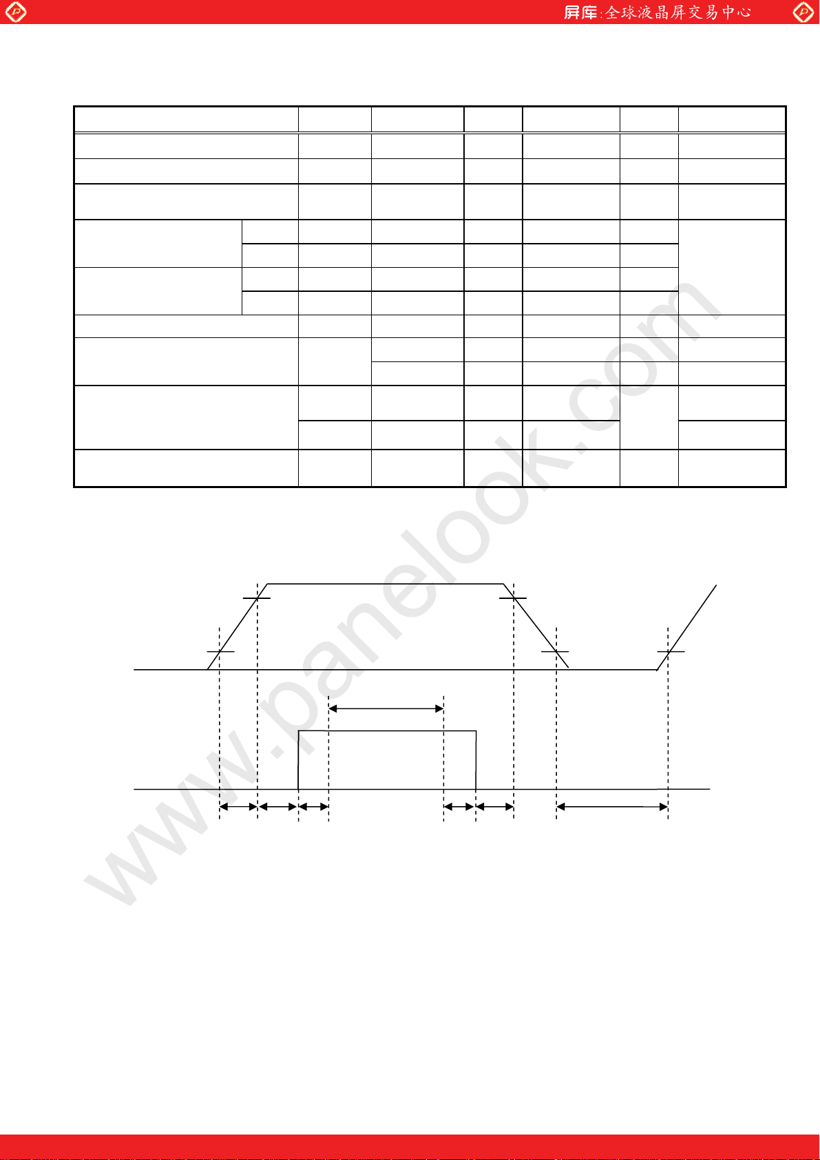
*1) Power and signals sequence:
t3
d t4
0.9VCC
0.1VCC
t4
0.1VCC
LCD Power Supply
Logic Signal
0.9VCC
0.1VCC
0.1 ms d t1 d10ms 200ms
0 < t2
0 < t3
d 50ms 200ms d t5
d 50ms 0 d t6
VCC
data
t2
t1
Backlight Power Supply
t5 t6
data: RGB DATA, DCLK, DENA, MODE, SC
MITSUBISHI Confidential (5/29) AA121XN11-CE-01_02_00
One step solution for LCD / PDP / OLED panel application: Datasheet, inventory and accessory!
www.panelook.com
Global LCD Panel Exchange Center
A
A
A
A
VCC-dip conditions:
www.panelook.com
1) When 2.6 V
d VCC < 3.0 V, td d 10 ms
2) When VCC < 2.6 V
VCC-dip conditions should also follow the power and signals sequence.
VCC
3.0 V
2.6 V
td
*2) VCC = +3.3 V , f
= 48.4 kHz, fV= 60 Hz, f
H
= 65 MHz
CLK
Display image at typical power supply current value is 256-gray-bar pattern (8 bit), 768 line mode.
*3) Fuse
Parameter Fuse Type Name Supplier Remark
VCC FCC16162AB Kamaya Electric Co., Ltd. *)
*) The power supply capacity should be designed to be more than the fusing current.
(2) Backlight
ITEM SYMBOL MIN. TYP. MAX. UNIT Remarks
-- (18) (21.6) V IF = 120 mA, Ta = 25°C, *2)
LED Voltage VF
-- -- (22.2) V IF = 120 mA, Ta = 0°C
-- -- (22.6) V
IF = 120 mA, Ta = 20°C
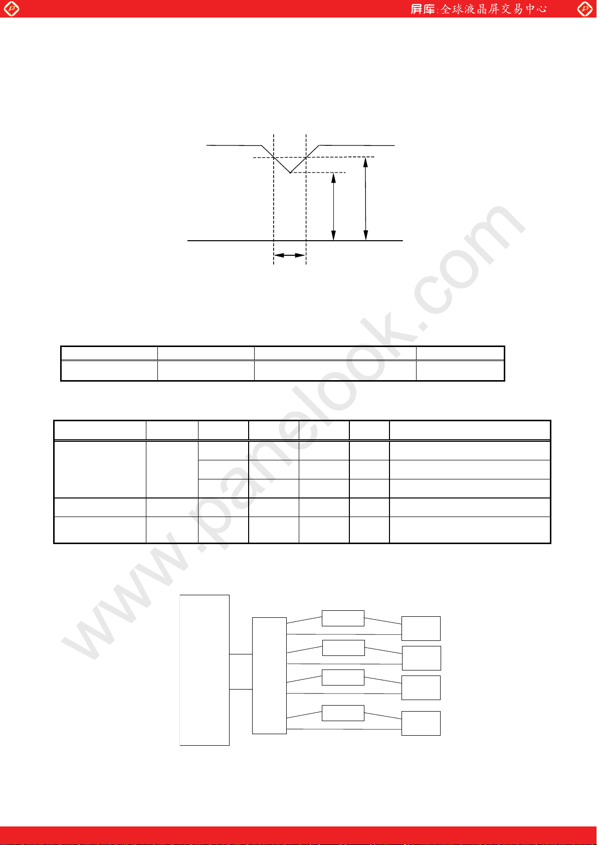
LED Current IF -- (120) (130) mA Ta = 25°C, *1), *3)
LED Life Time LT 80,000 100,000 -- h
IF = 120 mA, Ta = 25°C
*4), *5), Continuous operation
[Note]
*1) Constant Current Drive
*2) The Voltage deviation between strings: |V
fMAX
– V
fMIN
| d 2V
*3) LED Current measurement method:
LCD
Module
C1
1
C2
2
㩷
C3
3
A
A
A
Power
Supply
Power
Supply
Power
Supply
C4
4
A
Power
Supply
*4) LED life time is defined as the time when the brightness becomes 50% of the initial value.
*5) The life time of the backlight depends on the ambient temperature. The life time will decrease
under high temperature.
MITSUBISHI Confidential (6/29) AA121XN11-CE-01_02_00
One step solution for LCD / PDP / OLED panel application: Datasheet, inventory and accessory!
www.panelook.com
Global LCD Panel Exchange Center
p
(3) Touch Panel
Electrical Characteristics Ambient temperature: Ta = 25°C
ITEM SYMBOL MIN. TYP. MAX. UNIT Remarks
Touch Panel Voltage VDD5 (4.5) 5.0 (5.5) V *1)
Touch Panel Current ICCtp -- (50) (200) mA
Permissive Input
Ripple Voltage
High VIHtp
Logic Input Voltage
Low VILtp 0 --
High IOH
Logic Output Current
Low IOL 0 -- (5) mA
Multi-Touch Points -- 2 -- point
Position Accuracy
Position Coordinate
Output Rate (standard)
www.panelook.com
VRPtp -- -- 100 mVp-p
(0.8uVDD5)
(5.0)
'Ex
'Ey
-- -- (100) --
-- -- (60) --
(3)
(4.5)
-- VDD5 V
(0.2uVDD5)
-- 0 mA
-- (3) mm Inner area*4)
-- (4.5) mm Outer frame*4)
sps
VDD5 = +5.0 V
V
Single touch
Dual touch
CKW
RESET
*2)
*3)
SC
DIN
*5)
Dual Touch Detection Distance
*1) Power and signals sequence:
0.1 ms d t1 d10ms (200) ms d t4
0 < t2 d 50 ms (2000) ms d t5
0 < t3 d 50 ms 0 d t6
0.9×VDD5
0.1×VDD5
㪣㫆㪾㫀㪺㩷 㪪㫀㪾㫅㪸㫃㩷
t1 t2 t5 t6 t3 t4
Initialization of touch panel controller (calibration of touch panel) is carried out during period
between power supply turning on and start of touch panel operation (t1+t2+t5), therefore please do
not touch surface with finger, hold hands near touch surface, nor put conductive material like
metal on touch panel.
If the calibration is not able to be carried out successfully at the initialization process, touch panel
may not work properly for sometime.
'dx
'dy
Touch
(40) -- -- mm *4)
VDD5
0.9×VDD5
0.1×VDD5
anel operatingperiod
*2) Ripple noise of touch panel power supply affects stability of touch detection and position accuracy.
Therefore please use stabilized power supply to touch panel.
*3) Applied to CKW(2pin),SC(3pin),DIN(5pin),RESET(9pin).
For, please input signal of USB2.0 compliance to D(10pin) & D (11pin).
MITSUBISHI Confidential (7/29) AA121XN11-CE-01_02_00
One step solution for LCD / PDP / OLED panel application: Datasheet, inventory and accessory!
www.panelook.com
Global LCD Panel Exchange Center
www.panelook.com
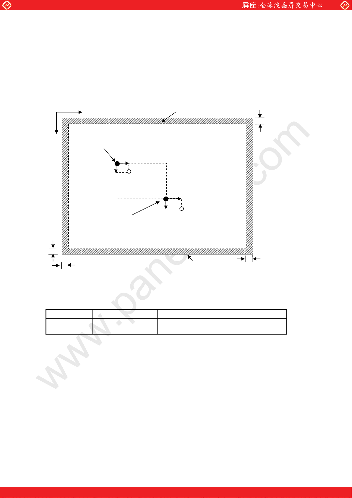
*4) Area of the finger touch is based on 10 mm in diameter.
Linearity is written as the difference of an actual touch position and the position coordinate which
a touch controller outputs as an error ('Ex and 'Ey stand for error length in the direction of X, Y,
respectively). Dual-point touch detection distance is shown in following figure.
The coordinates accuracy of peripheral part is valid when one-point touched.
Y
8mm
X
Touched position
6mm
Outer frame(hatched line area
)
8mm
Ex
Δ
Ey
Δ
Output
coordinate
x
Δd
Touched position
Ey
Δ
Δd
Ex
Δ
Output
coordinate
y
LCD active area
8mm
*5) The time interval of touch position coordinate output under an initial parameter condition
*6) Fuse
Parameter Fuse Type Name Supplier Remark
VCC FCC16501AB Kamaya Electric Co., Ltd. *)
*) The power supply capacity should be designed to be more than the fusing current.
MITSUBISHI Confidential (8/29) AA121XN11-CE-01_02_00
One step solution for LCD / PDP / OLED panel application: Datasheet, inventory and accessory!
www.panelook.com

Global LCD Panel Exchange Center
V
5. INTERFACE PIN CONNECTION
(1)CN 1(INTERFACE SIGNAL)
Used connector: 20186-020E-11F (I-PEX) or FI-SEB20P-HFE (JAE)
Corresponding connector: 20197-20U-F (I-PEX) or FI-S20S, FI-SE20ME (JAE)
Pin
No.
*1) Metal frame is connected to signal GND.
*2) Recommended wiring of Pin 17,18 (6 bit input)
Symbol
1 VCC
2 VCC
3 GND
4 GND
5
Link 0
6 Link 0+ R0, R1, R2, R3, R4, R5, G0 R2, R3, R4, R5, R6, R7, G2 R0, R1, R2, R3, R4, R5, G0
7 GND
8
Link 1
9 Link 1+ G1, G2, G3, G4, G5, B0, B1 G3, G4, G5, G6, G7, B2, B3 G1, G2, G3, G4, G5, B0, B1
10 GND
11
Link 2
12 Link 2+ B2, B3, B4, B5, DENA B4, B5, B6, B7, DENA B2, B3, B4, B5, DENA
13 GND
14
CLKIN Clock m
15 CLKIN+
16 GND
17
Link3
18 Link3+ See: *2) R0, R1, G0, G1, B0, B1 R6, R7, G6, G7, B6, B7
19 MODE Low=ISP 6 bit compatibility mode
20 SC
R0, R1, R2, R3, R4, R5, G0 R2, R3, R4, R5, R6, R7, G2
G1, G2, G3, G4, G5, B0, B1 G3, G4, G5, G6, G7, B2, B3
B2, B3, B4, B5, DENA B4, B5, B6, B7, DENA
See: *2) R0, R1, G0, G1, B0, B1
Scan direction control. ( Low : Normal , High : Reverse )
Function (ISP 6 bit compatibility mode)
6 bit input 8 bit input
+3.3 V Power supply
+3.3 V Power supply
www.panelook.com
GND
GND
GND
GND
GND
Clock +
GND
Function (ISP 8 bit
compatibility mode)
m
m
m
m
R0, R1, R2, R3, R4, R5, G0
m
G1, G2, G3, G4, G5, B0, B1
m
B2, B3, B4, B5, DENA
m
m
m
R6, R7, G6, G7, B6, B7
High=ISP
8 bit compatibility mode
m
LVDS
transmitter
LOW data
Pin 17
Pin 18
or
680
620
CC
Ω
Pin 17
Pin 18
Ω
MITSUBISHI Confidential (9/29) AA121XN11-CE-01_02_00
One step solution for LCD / PDP / OLED panel application: Datasheet, inventory and accessory!
www.panelook.com
 Loading...