

Page 1
Global LCD Panel Exchange Center
www.panelook.com
PRELIMINARY
ECR # REV. HIST. DESCRIPTION APPROVED DATE
A First release Allen Houck 11/28/01
TECHNICAL SPECIFICATION
AA121SK22
12.1-
INCH SVGA
I
NDUSTRIAL APPLICATIONS
A
PPROVALS DATE
ENG. ALLEN HOUCK 11/28/01
MKTG. DALE MAUNU
ADI
11/28/01
F
OR
OPTREX CORPORATION
TFT-LCD MODULE
12.1-
INCH SVGA COLOR
AA121SK22
SIZE OPTREX CORPORATION SPECIFICATION REV.
A
One step solution for LCD / PDP / OLED panel application: Datasheet, inventory and accessory!
AA121SK22
A
SHEET 1 OF 21
www.panelook.com
Page 2
Global LCD Panel Exchange Center
NO. ITEM PAGE
— COVER 1
— TABLE OF CONTENTS 2
www.panelook.com
PRELIMINARY
TABLE OF CONTENTS
1 OVERVIEW 3
2 ABSOLUTE MAXIMUM RATINGS 4
3 ELECTRICAL CHARACTERISTICS 4, 5, 6
4 INTERFACE PIN CONNECTION 7, 8
5 INTERFACE TIMING 9, 10, 11
6 BLOCK DIAGRAM 12
7 MECHANICAL SPECIFICATION 13, 14
8 OPTICAL CHARACTERISTICS 15, 16
9 RELIABILITY TEST CONDITION 17
11
HANDLING PRECAUTIONS FOR TFT-LCD
MODULE
18, 19
SIZE OPTREX CORPORATION SPECIFICATION REV.
A
One step solution for LCD / PDP / OLED panel application: Datasheet, inventory and accessory!
AA121SK22
A
SHEET 2 OF 21
www.panelook.com
Page 3
Global LCD Panel Exchange Center
www.panelook.com
PRELIMINARY
1. OVERVIEW
1.1. Description: The AA121SK22 is a 12.1-inch color TFT-LCD (Thin Film Transistor Liquid Crystal
Display) module composed of a LCD panel, driver ICs, a control circuit, and a backlight. Input power
voltage is either 3.3 or 5.0 V, not including power for the backlight. Both 3.3V-CMOS and
5.0V-CMOS levels are acceptable for logic input. Data and control signal interface is digital CMOS.
The display module supports 262,144 colors by applying 18 bits digital data (6 bits per sub pixel,
RGB). The display module resolution is 800 × 600 pixels. Inverter for backlight is not included in this
module.
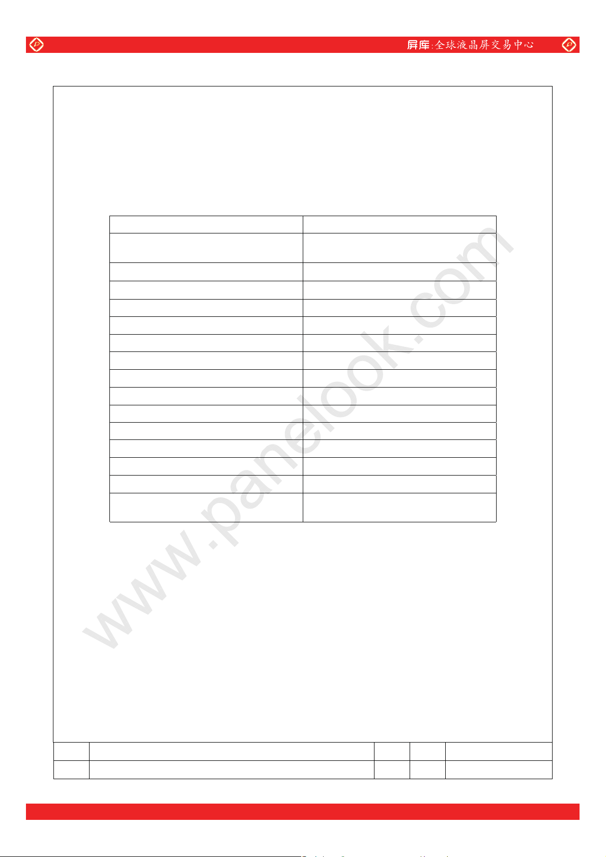
1.2. General specifications summary table:
ITEM SPECIFICATION
Display Area (mm)
Number of Pixels
Pixel Pitch (mm)
Color Pixel Arrangement RGB Vertical Stripe
Number of colors 260 K (6 bits/color)
Wide Viewing Angle Technology Optical Compensation Film
Surface Treatment Anti-glare and Hard-coating 3H
Electrical Interface CMOS(VI=3~5V)
Optimum Viewing Angle (Contrast) 6 o’clock
Module Size (mm)
Module Mass (g) 740
1.3. Product Disclaimer
The LCD products listed in this document are not suitable for safety related applications that do not
have redundant back-up system(s). These LCD products are not designed for use as a single source
safety related application, and are not recommended for applications in
environment may be affected in the event of the failure of the LCD product. The LCD products should
not be used in such things as:
(i) aircraft navigation or aerospace equipment;
(ii) nuclear reactor control systems;
(iii) any application where
life support systems); or
(iv) military and submarine critical systems.
The LCD products are designed for typical industrial applications such as, but not are limited to the
following: computers, office
measurement devices, communication equipment, point of sale, medical imaging, automotive, and
various other consumer products. If there are any questions regarding the use, ability or application
of these LCD products,
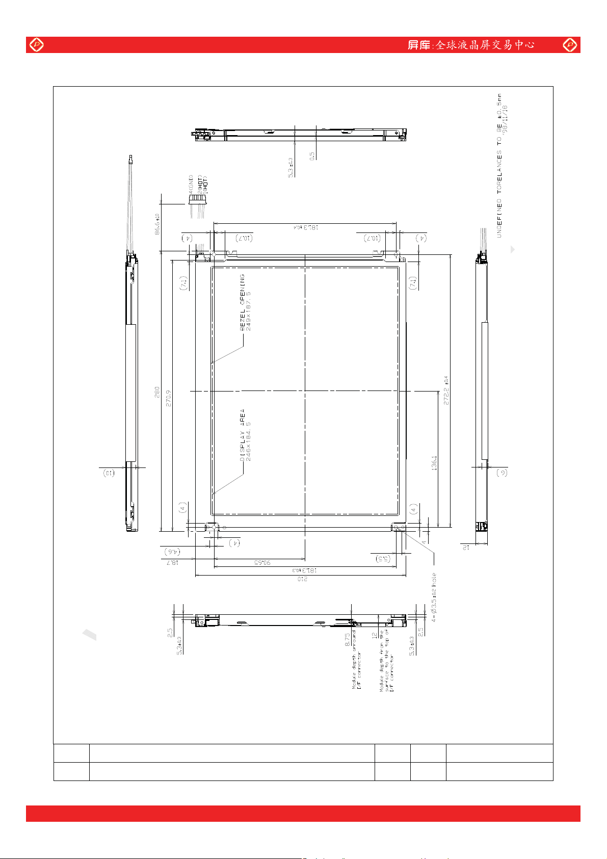
246.0(H) × 184.5 (V)
(12.106-inch diagonal)
800 (H) × 600 (V)
0.3075(H) × 0.3075 (V)
Display Mode Normally White TN
Luminance 300(cd/m 2) (Typ.)
Viewing Angle
Backlight Unit 2 replaceable CCFLs edge-light
failure or inaccuracy might cause death or personal injury (e.g.,
equipment, industrial controllers, audio and visual equipment, test and
please contact an authorized sales representative.
−60 ~ 60° (H), −50 ~ 40° (V) (Typ.)
280.0 (W) × 210.0 (H) × 12.0 (D)
(top)
which human life and/or
SIZE OPTREX CORPORATION SPECIFICATION REV.
A
AA121SK22
A
SHEET 3 OF 21
One step solution for LCD / PDP / OLED panel application: Datasheet, inventory and accessory!
www.panelook.com
Page 4
Global LCD Panel Exchange Center
www.panelook.com
PRELIMINARY
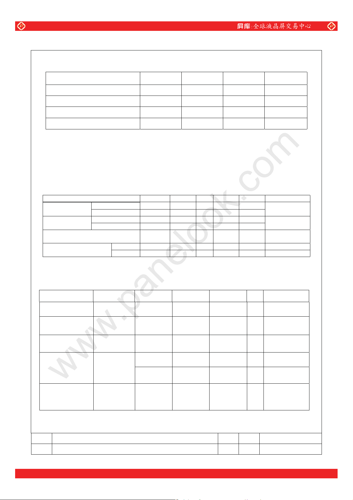
2. ABSOLUTE MAXIMUM RATINGS
2.1. Summary Table:
ITEM SYMBOL MIN MAX UNIT
Power Supply Voltage for LCD VCC 0 6.0 V
Logic Input Voltage VI 0 6.5 V
Operation Temperature *2.2) Top 0 50 °C
Storage Temperature *2.2) T
stg
−20
60 °C
2.2. Note:
T
T
≤ 40°C: 90%RH max. without condensation
op, Tstg
> 40°C: Absolute humidity shall be less than the value of 90%RH at 40°C without
op, Tstg
condensation.
3. ELECTRICAL CHARACTERISTICS
3.1. Conditions: TFT-LCD module ambient temperature is 25°C
3.2. Summary table:
ITEM SYMBOL MIN Typ. MAX UNIT Remarks
3.3V powered VCC 3.0 3.3 3.6 V Power Supply
Voltage for LCD
Power Supply
Current LCD
5.0V powered V
3.3V powered ICC — 335 430 mA
5.0V powered I
Permissive Input
Ripple Voltage
Logic Input
Voltage
High VIH 2.0 — 5.25 V
Low V
3.3. Backlight
3.3.1. This Backlight has two lamps. The table below shows data for both two lamps.
3.3.2. The TFT-LCD module has four identical lamps operated independently.
3.3.3. Operation of all lamps is required in order to meet all the parameters in
ITEM SYMBOL MIN TYP MAX UNIT Remarks
4.75 5.0 5.25 V
CC
— 235 340 mA
CC
— — 100 mVp-p VCC=+3.3/5.0V
V
RP
0 — 0.8 V
IL
the AA121SK22 specification.
Section 3.4.
Section 3.4.
Lamp Voltage V
Lamp Current IL
Inverter Frequency FI 30
Starting Lamp
Voltage
— 600 — V IL=10.0mA
L
6.0
(3.0mA/Lamp)
1000
V
S
1200
10.0
(5.0mA/Lamp)
—
— —
12.0
(6.0mA/Lamp)
60 kHz
mA Section 3.4.
V
V
— —
Lamp Life Time TL 50000 — — h
3.4. Notes
SIZE OPTREX CORPORATION SPECIFICATION REV.
A
AA121SK22
A
SHEET 4 OF 21
One step solution for LCD / PDP / OLED panel application: Datasheet, inventory and accessory!
Ta=0°C
Ta=25°C
I
=10.0mA
L
Continuous
Operation
Section 3.4.
www.panelook.com
Page 5
Global LCD Panel Exchange Center
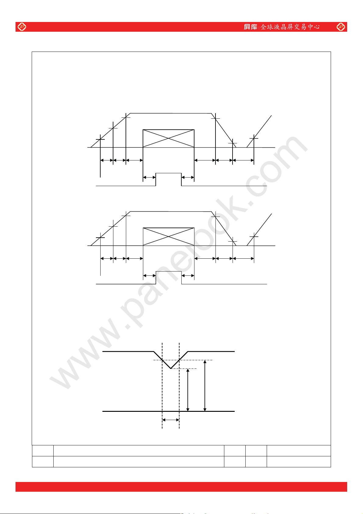
3.4.1. Power and Signals sequence :
t0 ≤ 1ms 0 < t4 ≤ 50ms
t1 ≤ 15ms 400ms ≤ t5
0 < t2 ≤ 200ms 200ms ≤ t6
0 < t3 ≤ 1sec 0 < t7
3.4.1.1. 3.3V powered
3.0V
2.1V
1.7V
www.panelook.com
PRELIMINARY
Vcc
DCLK, HD, VD, DENA
RGB Data
3.0V
0.5V
3.4.1.2. 5.0V powered
1.7V
3.4.2. V
-dip conditions :
CC
3.4.2.1. 3.3V powered
1) When 2.7V ≤ V
td ≤ 10ms
2) When V
V
< 2.7V
CC
-dip conditions should also follow the Power and Signals sequence.
CC
t1 t2 t3
t0
Backlight
t6 t7
4.5V
2.1V
t1 t2 t3
t0
< 3.0V
CC
DCLK, HD, VD, DENA
Vcc
RGB Data
Backlight
t6 t7
t4
4.5V
t4
0.5V
t5
1.7V
t5
VCC
3.0V
2.7V
td
SIZE OPTREX CORPORATION SPECIFICATION REV.
A
AA121SK22
A
SHEET 5 OF 21
One step solution for LCD / PDP / OLED panel application: Datasheet, inventory and accessory!
www.panelook.com
Page 6
Global LCD Panel Exchange Center
www.panelook.com
PRELIMINARY
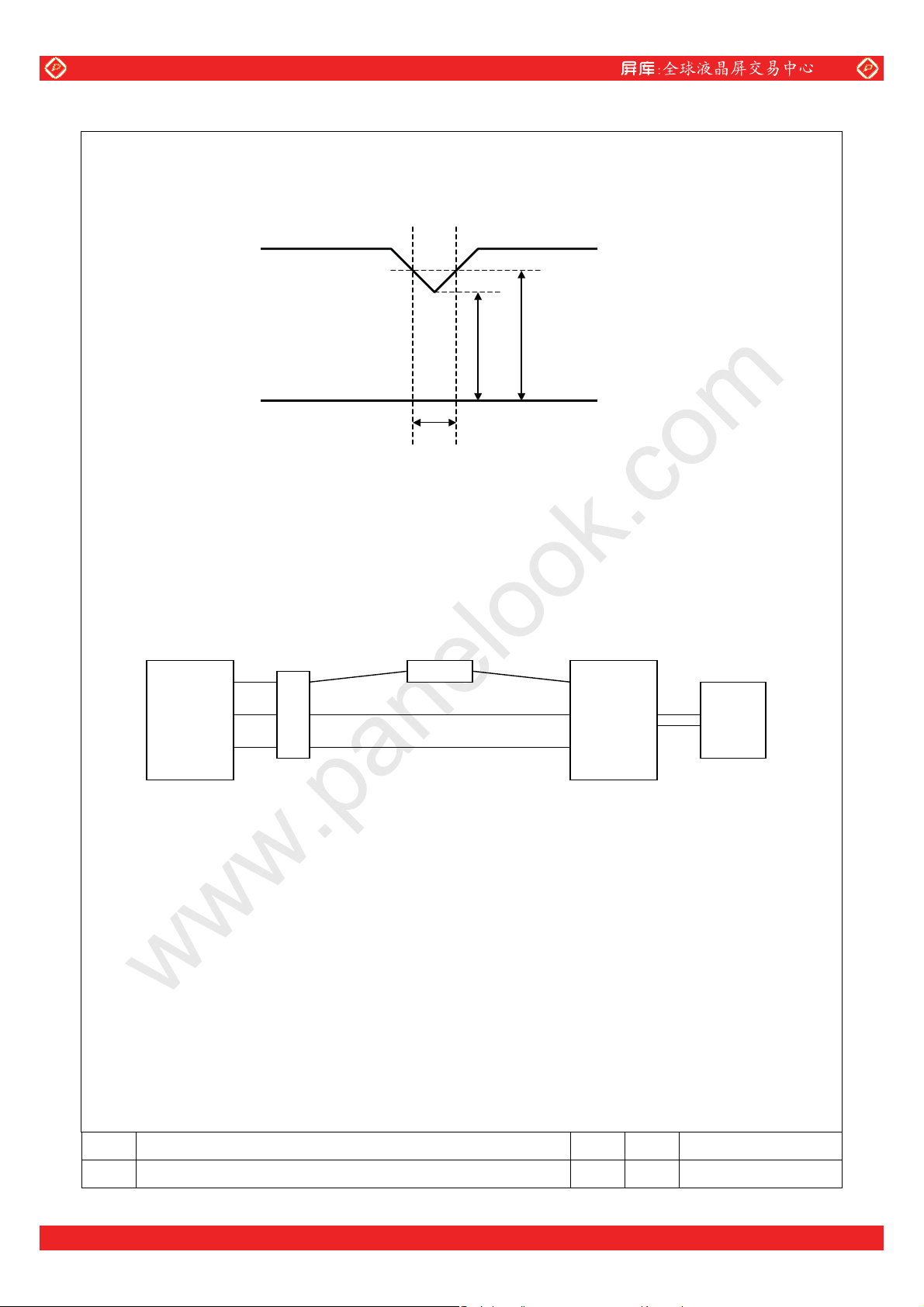
3.4.2.2. 5.0V powered
1) When 4.2V ≤ V
td ≤ 10ms
2) When V
V
< 4.2V
CC
-dip conditions should also follow the Power and Signals sequence.
CC
3.4.3. Test condition for I
64 gray-bar pattern
600 line mode
= +3.3 / 5.0V, fH=37.9kHz, fV=60.3Hz, f
V
CC
3.4.4. Please do not supply 3.6~4.75V constantly as Power Supply Voltage for LCD.
The condition is shown as t1 ≤ 15ms.
3.4.5. Lamp current measurement method (The current meter is inserted in low voltage line)
< 4.5V
CC
Typical:
CC
td
=40MHz
CLK
4.2V
VCC
4.5V
LCD
Module
CTL
CTH
CTH
A
Inverter
Power
Supply
3.4.6. The operating frequency of the backlight inverter may produce interference with horizontal
synchronous frequency. This may cause a horizontal ‘beat’ to be visible on the display. To avoid this
phenomenon, please adjust backlight inverter frequency and keep the inverter as far
from module
(physically) as possible. Use of shielding between the backlight inverter and the display module is
also effective to reduce interference.
3.4.7. Lamp life time is defined as the time either when the luminance becomes 50% of the initial value
under the standard condition, or when the starting lamp voltage does not meet the value specified in
this table.
3.4.8. The life time of the backlight depends on the ambient temperature. The life time will decrease under
low/high temperature.
SIZE OPTREX CORPORATION SPECIFICATION REV.
A
AA121SK22
A
SHEET 6 OF 21
One step solution for LCD / PDP / OLED panel application: Datasheet, inventory and accessory!
www.panelook.com
Page 7
Global LCD Panel Exchange Center
www.panelook.com
PRELIMINARY
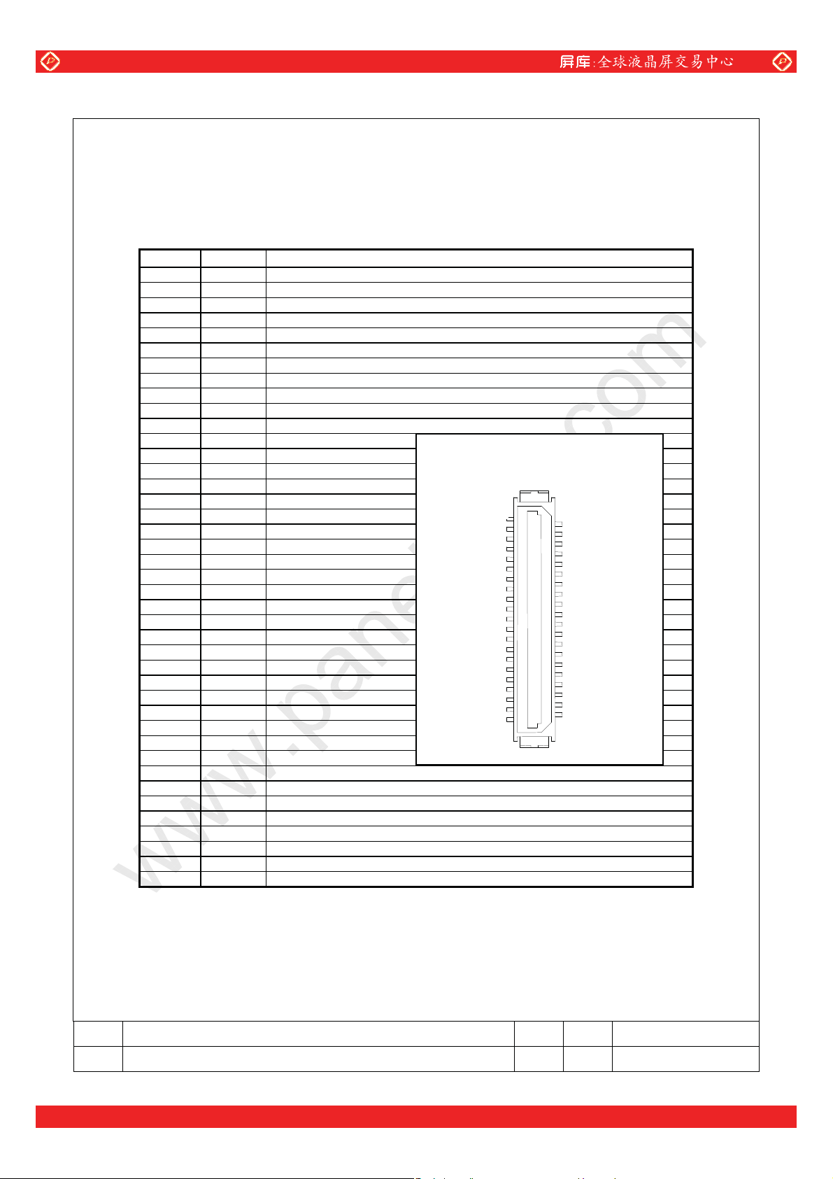
4. INTERFACE CONNECTORS PIN ASSIGNMENT
4.1. Input connector type (See paragraph 6.)
4.2. Input connector pin assignment table:
4.2.1. Input connector CN1 : DF9B-41P-1V (Hirose)
Corresponding connector : DF9B-41S-1V (Hirose)
PIN NO. SYMBOL FUNCTION
1 GND Signal Ground
2 DCLK Pixel clock
3 GND Signal Ground
4 HD Horizontal sync
5 VD Vertical sync
6 GND Signal Ground
7 GND Signal Ground
8 GND Signal Ground
9 R0 Red data(LSB)
10 R1 Red data
11 R2 Red data
12 GND Signal Ground
13 R3 Red data
14 R4 Red data
15 R5 Red data(MSB)
16 GND Signal Ground
17 GND Signal Ground
18 GND Signal Ground
19 G0 Green data(LSB)
20 G1 Green data
21 G2 Green data
22 GND Signal Ground
23 G3 Green data
24 G4 Green data
25 G5 Green data(MSB)
26 GND Signal Ground
27 GND Signal Ground
28 GND Signal Ground
29 B0 Blue data(LSB)
30 B1 Blue data
31 B2 Blue data
32 GND Signal Ground
33 B3 Blue data
34 B4 Blue data
35 B5 Blue data(MSB)
36 GND Signal Ground
37 DENA Data enable
38 NC Not Connected
39 VCC +3.3/5.0V Power supply
40 VCC +3.3/5.0V Power supply
41 TEST This pin should be open. Test signal output for only internal test use.
*Note: The metal frame of the TFT-LCD module is connected to ground.
Top view of input connector pin
assignment
1
41
2
40
SIZE OPTREX CORPORATION SPECIFICATION REV.
A
AA121SK22
A
SHEET 7 OF 21
One step solution for LCD / PDP / OLED panel application: Datasheet, inventory and accessory!
www.panelook.com
Page 8

Global LCD Panel Exchange Center
4.2.2. CN2
Backlight-side connector: BHR-04VS-1 (JST)
Inverter-side connector: SM04(4.0)B-BHS-1(JST)
PIN NO. SYMBOL FUNCTION
1,2 CTH V
4 CTL V
*Note: The metal frame of the TFT-LCD module is connected to ground.
www.panelook.com
PRELIMINARY
(High voltage)
BLH
(Low voltage)
BLL
SIZE OPTREX CORPORATION SPECIFICATION REV.
A
AA121SK22
A
SHEET 8 OF 21
One step solution for LCD / PDP / OLED panel application: Datasheet, inventory and accessory!
www.panelook.com
Page 9

Global LCD Panel Exchange Center
PRELIMINARY
5. INTERFACE TIMING
5.1. Timing Chart
5.1.1. Pixel Timing Chart
www.panelook.com
t
CLK
t
WCH
t
WCL
DCLK
DATA
DENA, HD, VD
5.1.2. Horizontal Timing Chart
DCLK
DATA
(R,G,B)
t
DENA
HD
HFP
t
WHL
HBP
2.0V
0.8V
tDs tDh
2.0V
0.8V
First Data
1 2 799 800 3 Invalid Data Invalid Data
t
t
HA
tH=1/fH
Last Data
5.1.3. 5.1.3 Vertical Timing Chart
HD
LINE DATA
t
t
VFP
DENA
VD
t
WVL
VBP
SIZE OPTREX CORPORATION SPECIFICATION REV.
A
AA121SK22
1 2 599 600 3 Invalid Data Invalid Data
tVA
tV=1/fV
A
SHEET 9 OF 21
One step solution for LCD / PDP / OLED panel application: Datasheet, inventory and accessory!
www.panelook.com
Page 10

Global LCD Panel Exchange Center
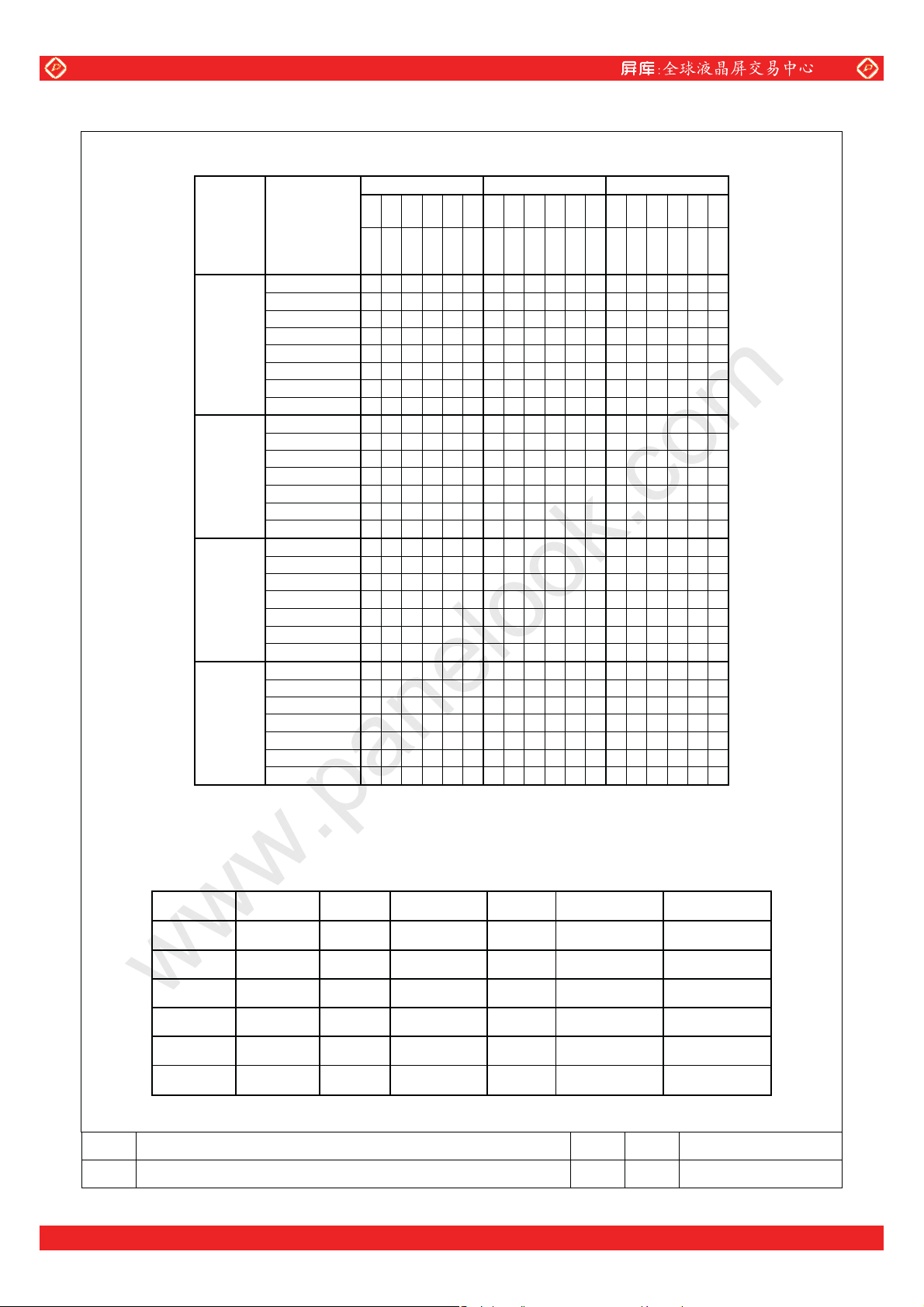
5.2. Timing Specification
ITEM SYMBOL MIN TYP MAX UNIT
Frequency f
DCLK *
Period t
Low Width t
High Width t
Set up Time tDS 4 — — ns DATA
(R, G, B, DENA
HD, VD)
Hold Time t
Horizontal
Active Time
Horizontal
Front Porch
Horizontal
DENA
Back Porch
Vertical
Active Time
Vertical
Front Porch
Vertical
Back Porch
Frequency fH 35.2 37.9 39.2 kHz
HD
Period tH 25.5 26.4 28.4
Low Width t
Frequency fV 55.0 60.3 64.2 Hz
VD
Period tV 15.6 16.6 18.2 ms
Low Width t
*Note 1: DATA is latched at fall edge of DCLK in this specification.
*Note 2: Polarities of HD and VD are negative in this specification.
*Note 3: DENA should always be positive polarity as shown in the timing specification.
*Note 4: DCLK and H
D should be applied continuously at the input connector of the TFT-LCD module
during operation, subject to Section 3.4.1.
www.panelook.com
PRELIMINARY
35 — 40 MHz
CLK
25.0 — 27.8 ns
CLK
10 — — ns
wCL
10 — — ns
wCH
4 — — ns
DH
800 800 800 t
t
HA
0 — — t
t
HFP
10 — — t
t
HBP
600 600 600 tH
t
VA
1 — — tH
t
VFP
2 — — tH
t
VBP
5 — — t
WHL
1 — — tH
WVL
CLK
CLK
CLK
μs
CLK
SIZE OPTREX CORPORATION SPECIFICATION REV.
A
AA121SK22
A
SHEET 10 OF 21
One step solution for LCD / PDP / OLED panel application: Datasheet, inventory and accessory!
www.panelook.com
Page 11
Global LCD Panel Exchange Center
5.3. Color Data Assignment
COLOR
BASIC
COLOR
RED
GREEN
BLUE
INPUT
DATA
BLACK 000000000000000 0 0 0
RED(63) 111111000000000 0 0 0
GREEN(63) 000000111111000 0 0 0
BLUE(63) 000000000000111 1 1 1
CYAN 000000111111111 1 1 1
MAGENTA 111111000000111 1 1 1
YELLOW 111111111111000 0 0 0
WHITE 111111111111111 1 1 1
RED(0) 000000000000000 0 0 0
RED(1) 000001000000000 0 0 0
RED(2) 000010000000000 0 0 0
¦
¦
RED(62) 111110000000000 0 0 0
RED(63) 111111000000000 0 0 0
GREEN(0) 000000000000000 0 0 0
GREEN(1) 000000000001000 0 0 0
GREEN(2) 000000000010000 0 0 0
¦
¦
GREEN(62) 000000111110000 0 0 0
GREEN(63) 000000111111000 0 0 0
BLUE(0) 000000000000000 0 0 0
BLUE(1) 000000000000000 0 0 1
BLUE(2) 000000000000000 0 1 0
¦
¦
BLUE(62) 000000000000111 1 1 0
BLUE(63) 000000000000111 1 1 1
5.3.1. Definitions
Gray scale: Color (n) → n indicates gray scale level.
Data: 1=High, 0=Low
5.3.2. Data Mapping
D(1,1) D(2,1)
www.panelook.com
PRELIMINARY
R DATA G DATA B DATA
R5R4R3R2R1R0G5G4G3G2G1G0B5B4B
M
S
B
L
M
S
S
B
B
L
M
S
S
B
B
—
D(X,1)
—
D(799, 1) D(800, 1)
B
3
2
B
B
1
0
L
S
B
D(1,2) D(2,2)
—
D(X,2)
—
D(799, 2) D(800, 2)
l l + l + l l
D(1,Y) D(2,Y)
—
D(X,Y)
—
D(799,Y) D(800, Y)
l l + l + l l
D(1,599) D(2,599)
D(1,600) D(2,600)
—
—
D(X,599)
D(X,600)
—
—
D(799,599) D(800, 599)
D(799, 600) D(800, 600)
SIZE OPTREX CORPORATION SPECIFICATION REV.
A
AA121SK22
A
SHEET 11 OF 21
One step solution for LCD / PDP / OLED panel application: Datasheet, inventory and accessory!
www.panelook.com
Page 12

Global LCD Panel Exchange Center
6. BLOCK DIAGRAM
www.panelook.com
PRELIMINARY
Timing signal
Display Data
Power
BACKLIGHT
Backlight
Timing
Converter
CN1 I/F Connector
Power
Supply
Circuit
Drivers (Gate)
G1
G2
G600
S1
S2
Drivers (Source)
TFT-LCD
800×3×600
S2399
CN2
S2400
CN2
CCFL
CCFL
SIZE OPTREX CORPORATION SPECIFICATION REV.
A
AA121SK22
1
2
4
A
SHEET 12 OF 21
One step solution for LCD / PDP / OLED panel application: Datasheet, inventory and accessory!
www.panelook.com
Page 13

Global LCD Panel Exchange Center
www.panelook.com
PRELIMINARY
7. MECHANICAL SPECIFICATION
7.1. Front Side Drawing
SIZE OPTREX CORPORATION SPECIFICATION REV.
A
One step solution for LCD / PDP / OLED panel application: Datasheet, inventory and accessory!
AA121SK22
A
SHEET 13 OF 21
www.panelook.com
Page 14
Global LCD Panel Exchange Center
www.panelook.com
PRELIMINARY
SIZE OPTREX CORPORATION SPECIFICATION REV.
A
One step solution for LCD / PDP / OLED panel application: Datasheet, inventory and accessory!
AA121SK22
A
SHEET 14 OF 21
www.panelook.com
Page 15
Global LCD Panel Exchange Center
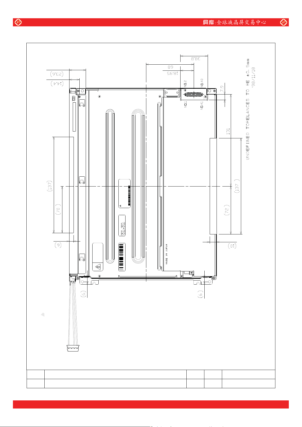
7.2. Rear Side Drawing
www.panelook.com
PRELIMINARY
[Note]
We recommend you referring to the detailed drawing for your design.
SIZE OPTREX CORPORATION SPECIFICATION REV.
A
One step solution for LCD / PDP / OLED panel application: Datasheet, inventory and accessory!
AA121SK22
A
SHEET 15 OF 21
www.panelook.com
Page 16

Global LCD Panel Exchange Center
Please contact our company sales representative when you need the detailed drawing.
www.panelook.com
PRELIMINARY
SIZE OPTREX CORPORATION SPECIFICATION REV.
A
One step solution for LCD / PDP / OLED panel application: Datasheet, inventory and accessory!
AA121SK22
A
SHEET 16 OF 21
www.panelook.com
Page 17

Global LCD Panel Exchange Center
(
)
(
)
www.panelook.com
PRELIMINARY
8. OPTICAL CHARACTERISTICS
8.1. Summary table:
ITEM
Contrast Ratio CR
Luminance
Response
Time
Viewing
Angle
Image Sticking tis 2 hours — — 2 s
Color
Coordinates
These items are measured using BM-5A (TOPCON) or LCD7000 (Otsuka Electronic) under the dark room
condition (no ambient light).
*); Condition: I
Ambient Temperature 25°C, V
Definitions of these measurement items are as follows:
1) Definition of Contrast Ratio
CR=ON (White) Luminance/OFF (Black) Luminance: average of 5 points below
2) Definition of Luminance
=ON (White) Luminance: average of 5 points below
L
W
Horizontal
Vertical
Horizontal
Vertical
Red
Green
Blue
White
=10.0mA, Inverter frequency: 47kHz
L
SYMBOL CONDITION MIN TYP MAX UNIT
100 300 —
250 300 — cd/m
— 20 40 ms
— 30 50 ms
−50~50 −60~60
−40~30 −50~40
—
—
0.532
0.316
0.296
0.519
0.137
0.151
0.296
0.338
−20~20
−20~20
0.562
0.346
0.326
0.549
0.167
0.181
0.326
0.368
— °
— °
— °
— °
0.592
0.376
0.356
0.579
0.197
0.211
0.356
0.398
1,1
LW
tr
tf
φ
θ
φ
θ
Rx
Ry
Gx
Gy
Bx
By
Bx
By
θ = φ = 0°
θ = φ = 0°
θ = φ = 0°
θ = φ = 0°
CR ≥≥≥≥ 10
LW ≥ 70%
θ = φ = 0°
=3.3/5.0V, signal timings are typical values in section 5.
CC
200 400 600
—
2
150
300
450
1
5
SIZE OPTREX CORPORATION SPECIFICATION REV.
A
AA121SK22
2
43
800, 600
A
SHEET 17 OF 21
One step solution for LCD / PDP / OLED panel application: Datasheet, inventory and accessory!
www.panelook.com
Page 18

Global LCD Panel Exchange Center
)
www.panelook.com
PRELIMINARY
8.2. Definitions
8.2.1. Contrast Ratio CR = ON (White) Luminance / OFF (Black) Luminance
8.2.2. Viewing Angle (θ , φ) - See drawing below:
Upper (+
Left (-)
LCD
panel
8.2.3. Definition of Response Time tr and tf:
White
90%
10%
θ
φ
Right (+)
Lower (-)
90%
10%
tr
8.2.4. Test Pattern for Image Sticking Test
Continuously display the test pattern shown in
completely white screen. The previous image shall not persist more than two seconds at 25°C.
White
Area
Black
the figure below for two-hours. Then display a
Cols 388-402
Rows 298 - 302
Black
Lines
SIZE OPTREX CORPORATION SPECIFICATION REV.
A
AA121SK22
A
SHEET 18 OF 21
One step solution for LCD / PDP / OLED panel application: Datasheet, inventory and accessory!
www.panelook.com
Page 19

Global LCD Panel Exchange Center
www.panelook.com
PRELIMINARY
9. RELIABILITY TEST CONDITIONS
9.1. Temperature and Humidity
TEST ITEM CONDITIONS
High Temperature and High Humidity Operation
Thermal Shock
High Temperature Storage
Low Temperature Storage
9.2. Shock and Vibration
TEST ITEM CONDITIONS
Shock (non-operating)
Vibration (non-operating)
40°C, 90%RH, 240 hours
(No condensation)
Between –20°C (1 hour) and
60°C (1 hour) 5 cycles
60°C, 96 hours
–20°C, 96 hours
2
Shock level: 1470 m/s
Waveform: half sinusoidal wave, 2 ms
Number of shocks: one shock input in each direction of three mutually
perpendicular axes for a total of six shock inputs
Vibration level: 9.8 m/s
Waveform: sinusoidal
Frequency range: 5 to 500 Hz
Frequency sweep rate: 0.5 octave/min
Duration: one sweep from 5 to 500 to 5Hz in each of three mutually
perpendicular axes (each x,y,z axis: 1 hour, total 3 hours)
(150G)
2
(1.0G)
9.3. Judgment Standard – Pass/Fail criteria for reliability tests is defined as follows:
Pass : Normal display image with no obvious non-uniformity and no line defect.
Fail : No display image, obvious non-uniformity, or line defect.
SIZE OPTREX CORPORATION SPECIFICATION REV.
A
AA121SK22
A
SHEET 19 OF 21
One step solution for LCD / PDP / OLED panel application: Datasheet, inventory and accessory!
www.panelook.com
Page 20

Global LCD Panel Exchange Center
www.panelook.com
PRELIMINARY
10. HANDLING PRECAUTIONS FOR TFT-LCD MODULE - Please observe the
recommendations included in this paragraph when handling the TFT-LCD
modules !
10.1. ASSEMBLY PRECAUTIONS
10.1.1. Please use the mounting hole on the module corners for installation and avoid bending or wrenching
LCD during assembly process. Do not drop, bend or twist the TFT-LCD module during handling.
10.1.2. Guidelines for designing the TFT-LCD module enclosure:
10.1.2.1. Housing case must be designed carefully so as not
wrench module. Mechanical stress to the TFT-LCD module may degrade the reliability and overall
performances of the display (like luminance uniformity degradation…etc.).
10.1.2.2. Keep sufficient clearance between LCD module back surface and housing when
mounted. Approximately 1.0 mm of the clearance in the design is recommended taking into account
the tolerance of LCD module thickness and mounting structure height on the housing.
10.1.2.3. When some parts, such as FPC cable and ferrite plate, are installed underneath the LCD
sufficient clearance is required, such as 0.5mm. This clearance is to be reconsidered when
additional parts are inserted for EMI countermeasures.
10.1.2.4. Choose carefully the inverter location to avoid any stress to the lamp cable. The lamp cable also
should not interfere with the module installation
10.1.2.5. Keep sufficient clearance between LCD module and the others components, such as inverter and
speaker so as not to interfere with the LCD module. Approximately 1.0 mm of the clearance in the
design is recommended.
10.1.2.6. Please connect the metal frame of the m
noise and EMI.
10.1.3. Do not apply pressure or scratch LCD panel surface with anything hard. Do not soil LCD panel
surface by touching with bare hands. (The anti-glare surface treatment is only effective when
module surface of the display is clean and unmarred.)
10.1.4. Do not apply pressure on any parts on the rear side such as source TCP, gate TCP, control circuit
board and FPCs during handling LCD module.
10.1.5. Wipe off LCD panel surface with absorbent cotton or soft cloth to
10.1.6. Wipe off immediately any liquids which may have accidentally being sprayed on LCD panel surface.
Droplets on the LCD panel surface may alter the quality of the image.
10.1.7. Do not disassemble the TFT-LCD module for any reasons. By doing so you void the
TFT-LCD module and is very likely that the performances will be degraded considerably.
10.1.8. Do not touch metal frames with bare hands and soiled gloves. If fingerprints or dirt are not cleaned
immediately with solvent it is very likely that permanent m
10.1.9. Disconnect the lamp wires before handling the inverter. Otherwise, it is possible to damage the lamp
and or the lamp wires by pulling it together with the inverter.
10.2. OPERATING PRECAUTIONS
10.2.1. Turn off the power supply
10.2.2. Do not change the setting of the adjustable resistors on TFT-LCD module subassemblies. The
adjustable resistors are properly set at the factory and any deviation from the factory setting will
compromise the performances of the TFT-LCD module.
10.2.3. When evaluating the optical characteristics of the display please note that will take longer time for the
backlight to stabilize if the ambient temperature is at the lower end of the temperature range.
10.2.4. Sudden changes of the ambient temperature may
TFT-LCD module and degrade the overall performances until the surfaces become dry again.
10.2.5. Follow-up the general safety rules applying to generic electronic products.
SIZE OPTREX CORPORATION SPECIFICATION REV.
to put stresses on LCD all sides and not to
the LCD module is
module, still
into the enclosure.
odule to GND in order to minimize the effect of external
clean the surface.
warranty of the
arks will be left on the metal surfaces.
before connecting and disconnecting signal input cable.
cause condensation on various surfaces of the
the
A
AA121SK22
A
SHEET 20 OF 21
One step solution for LCD / PDP / OLED panel application: Datasheet, inventory and accessory!
www.panelook.com
Page 21

Global LCD Panel Exchange Center
www.panelook.com
PRELIMINARY
10.3. PRECAUTIONS WITH ELECTRONICS
10.3.1. This LCD module uses CMOS integrated circuits and other components subject to be affected by
electrostatic discharges. Use ESD protection equipment and follow all ESD safety procedures when
handling the TFT-LCD modules.
10.3.2. Please remove protection film very slowly from the
discharge. It is recommended to lift the protection film starting from the lower left corner of the
module, and pulling diagonally toward the upper right corner.
10.4. STORAGE PRECAUTIONS
10.4.1. Do not leave the LCDs in the environment of high hu
10.4.2. Do not expose the TFT-LCD modules to temperatures below −20°C.
10.5. SAFETY PRECAUTIONS
10.5.1. When disposing LCDs it is recommended to break them into pieces. The broken pieces should be
washed with solvents such as acetone and ethanol. The residual solvent fro
burned.
10.5.2. If any liquid leaks out of a damaged glass cell and comes in contact with the hands, wash it off
thoroughly with soap and water.
10.6. OTHERS
10.6.1. Exposing the TFT-LCD module to strong incident light may negatively affect the display
characteristics
LCD module to direct sunlight or light with strong ultraviolet content.
10.6.2. Avoid any contact of the TFT-LCD module front surface with other objects or materials.
10.7. PACKAGING AND SHIPPING
10.7.1. Packaging box and inner case for
scratching during transportation. Do not open the packaging box unnecessarily.
10.7.2. Do not stack more than 5 boxes on top of each other because stack of 5 is maximum designed limit.
Do not turn over the boxes.
10.7.3. Avoid
10.7.4. Packaging box and the inner structures of it are made of cardboard. Avoid having the boxes in
excessive shock; the shipping boxes are not designed to be thrown. Excessive vibrations can
also damage the boxes and the TFT-LCD modules inside.
contact with water or in high hu
break, damaging the TFT-LCD modules inside.
because of polarizer film, color filter, and other materials degradation. Do not expose
LCD are designed to protect the LCDs from the damage or
midity environment which may cause the carton to become soft, or to
surface of LCD module to prevent electrostatic
midity and high temperature.
m this process should be
SIZE OPTREX CORPORATION SPECIFICATION REV.
A
AA121SK22
A
SHEET 21 OF 21
One step solution for LCD / PDP / OLED panel application: Datasheet, inventory and accessory!
www.panelook.com
 Loading...