

Mitsubishi Electric A960GOT, A970GOT, A975GOT, A985GOT User Manual

C
MIT
SUBIS
C
GOT
Human Machine Interface
User’s Manual
HI ELECTRI
Art. no.: 103490
01 04 2002
SH (NA)-4005-H
Graphical Operator Terminal
A960GOT, A970GOT,
A975GOT, A985GOT
MITSUBISHI ELECTRI
INDUSTRIAL AUTOMATION
SAFETY PRECAUTIONS
•
(Always read these instructions before using this equipment.)
Before using this product, please read this manual and the relevant manuals introduced in this manual
carefully and pay full attention to safety to handle the product correctly.
The instructions given in this manual are concerned with this product. For the safety instructions of the
programmable controller system, please read the CPU module user's manual.
In this manual, the safety instructions are ranked as "DANGER" and "CAUTION".
•
DANGER
!
CAUTION
!
Note that the !CAUTION level may lead to a serious consequence according to t he circumstances.
Always follow the instructions of both levels because they are important to personal safety.
Please save this manual to make it accessible when required and always forw ard it to the end user.
Indicates that incorrect handling may cause hazardous conditions,
resulting in death or severe injury.
Indicates that incorrect handling may cause hazardous conditions,
resulting in medium or slight personal injury or physical damage.
[Design Precautions]
!
DANGER
Some failures of the GOT main unit, communication module, communication board or cable may
•
keep the outputs on or off.
An external monitoring circuit should be provided to check for output signals which may lead to
a serious accident.
Not doing so can cause an accident due to false output or malfunction.
If a communication fault (including cable disconnection) occurs during monitoring on t he GOT,
•
communication between the GOT and PLC CP U is suspended and t he GOT becomes
inoperative.
For bus connection : The CPU becomes faulty and the GOT inoperative.
For other than bus connection : The GOT becomes inoperative.
A system where the GOT is used should be configured to perform any significant operation to
the system by using the switches of a device other than the GOT on the assumption that a GOT
communication fault will occ ur.
Not doing so can cause an accident due to false output or malfunction.
Do not use the GOT as the warning device that may cause a serious accident.
•
An independent and redundant hardware or mechanical interloc k is required to configure the
device that displays and outputs serious warning.
Failure to observe this instruction may result in an accident due to incorrect output or
malfunction.
A - 1 A - 1
[Design Precautions]
!
DANGER
Incorrect operation of the touch switch(s) may lead to a serious accident if the GOT backlight is
•
gone out.
When the GOT backlight goes out, the display section turns black and causes the monitor
screen to appear blank, while the input of the touch swit ch(s) still remains act ive.
This may confuse an operator in thinking that the GOT is in “screensaver” mode, who then tries
to release the GOT from this mode by touching the display section, which may cause a touch
switch to operate.
Note that the following occurs on the GOT when the backlight goes out.
The monitor screen disappears even when the screensaver is not set.
•
The monitor screen will not come back on by t ouching the display section, even if the
•
screensaver is set.
!
CAUTION
Do not bundle the control and communication cables with main-circuit, power or other wiring.
•
Run the above cables separately from such wiring and keep them a minimum of 100mm apart.
Not doing so noise can cause a malfunction.
[Mounting Precautions]
!
DANGER
Before installing or removing t he GO T main unit t o or from an enclos ure, alway s s wit ch off th e
•
GOT power externally in all phases.
Not doing so can cause a module failure or malfunction.
Before loading or unloading the communication board, communication module or memory board
•
to or from the GOT, always switch off the GOT power externally in all phases.
Not doing so can cause a module failure or malfunction.
!
CAUTION
The GOT should be used in the environment given in the general specifications of the GO T
•
user's manual.
Not doing so can cause an electric shock, fire, malfunction or product damage or deterioration.
When mounting the GOT main unit to an enclosure, tighten the mounting screws in the specifie d
•
torque range.
Undertightening can cause a drop, short circuit or malfunction.
Overtightening can cause a drop, short circuit or malfunction due to the damage of the screws
or module.
A - 2 A - 2
[Mounting Precautions]
!
CAUTION
When loading the communication board or communication module to the G OT main unit, fit it to
•
the connection interface of the GOT and tighten the mounting screws in the specified torque
range.
Undertightening can cause a drop, failure or malfunction.
Overtightening can cause a drop, failure or malfunction due to the damage of the screws or
module.
When loading the memory board into the GOT main unit, load it into its corresponding GO T slot
•
and tighten the mounting screws in the specified torque range.
Undertightening can cause a malfunction due to a contact fault.
Overtightening can cause a malfunction due to the damage of the screws or module.
When loading the PC card into the GOT main unit, insert and push it into its corresponding GO T
•
slot until the PC card eject button comes up.
Not doing so can cause a malfunction due to a contact fault.
Before loading or unloading the PC card to or from the GOT, set the memory card access switch
•
to the OFF position.
Not doing so can cause the PC card data to be corrupted.
When taking out the PC card, hold it with one hand and remove.
•
If removed without a hand support, the PC card may drop, resulting in breakage or damage.
[Wiring Precautions]
!
DANGER
Before starting wiring, always switch off the GOT power externally in all phases.
•
Not doing so may cause an electric shock, product damage or malfunction.
!
CAUTION
Please make sure to ground FG terminal, LG terminal, and protective ground terminal of the
•
GOT power supply unit by applying Class D Grounding (Cla ss 3 Gr ounding Method) or higher
which is used exclusively for the GOT.
Not doing so may cause an electric shock or malfunction.
Correctly wire the power supply module on the GOT after confirming the rated voltage and
•
terminal arrangement of the product.
Not doing so can cause a fire or failure.
Tighten the terminal screws of the GOT power supply section in the specified torque range.
•
Undertightening can cause a short circuit or malfunction.
Overtightening can cause a short circuit or malfunction due to the damage of the screws or
module.
Exercise care to avoid foreign matter such as chips and wire offcuts entering the module.
•
Not doing so can cause a fire, failure or malfunction.
A - 3 A - 3
[Wiring Precautions]
!
CAUTION
Plug the bus connection cable by inserting it into the connector of the connected module until it
•
"clicks".
After plugging, check that it has been inserted snugly.
Not doing so can cause a malfunction due to a contact fault.
Plug the communication cable into the connector of the connected module and tighten the
•
mounting and terminal screws in the specified torque range.
Undertightening can cause a short circuit or malfunction.
Overtightening can cause a short circuit or malfunction due to the damage of the screws or
module.
[Test Operation Precautions]
!
DANGER
Before performing test operation (bit device on/off, word device's present value changing,
•
timer/counter's set value and present value changing, buffer memory's present value changing)
for a user-created monitor screen, system monitoring, special module monitoring or ladder
monitoring, read the manual carefully to fully underst and how to operate the equipment.
During test operation, never change the data of the devices which are used to perform
significant operation for the system.
False output or malfunction can cause an accident.
[Startup/Maintenance Precautions]
!
DANGER
When power is on, do not touch the terminals.
•
Doing so can cause an electric shock or malfunction.
Before starting cleaning or terminal screw retightening, always switch off the power externally in
•
all phases.
Not switching the power off in all phases can cause a module failure or malfun ction.
Undertightening can cause a short circuit or malfunction.
Overtightening can cause a short circuit or malfunction due to the damage of the screws or
module.
!
CAUTION
Do not disassemble or modify the module.
•
Doing so can cause a failure, malfunction, injury or fire.
Do not touch the conductive and electronic parts of the module directly.
•
Doing so can cause a module malfunction or failure.
A - 4 A - 4
[Startup/Maintenance Precautions]
!
CAUTION
Do not disassemble or modify the module.
•
Doing so can cause a failure, malfunction, injury or fire.
Do not touch the conductive and electronic parts of the module directly.
•
Doing so can cause a module malfunction or failure.
The cables connected to the module must be run in ducts or clamped.
•
Not doing so can cause the module or cable to be damaged due to the dangling, motion or
accidental pulling of the cables or can cause a malfunction due to a cable connection fault.
When unplugging the cable connected to the module, do not hold and pull the cable portion.
•
Doing so can cause the module or cable to be damaged or can cause a malfunction due to a
cable connection fault.
[Backlight Changing Precautions]
!
DANGER
Before changing the backlight, always switch off the GOT power externally in all phases (w hen
•
the GOT is connected to the bus, the PLC CPU power must also be swit ched off externally in all
phases) and remove the GOT main unit from the enclosure.
Not switching the power off in all phases may cause an electric shoc k.
Not removing the unit from the enclosure can cause injury due to a drop.
!
CAUTION
When replacing the backlight, use the gloves.
•
Otherwise, it may cause you to be injured.
If you should directly touch the plated area of the main unit case with hand, be sure to wipe off
the fingerprint and so on, and install the main unit case.
Otherwise, it may cause a trouble or malfunction.
Start changing the backlight more than 5 minutes after switching the GOT power off.
•
Not doing so can cause a burn due to the heat of the backlight.
[Disposal Precautions]
!
CAUTION
When disposing of the product, handle it as industrial waste.
•
A - 5 A - 5
REVISIONS
The manual number is given on the bottom left of the back cover..
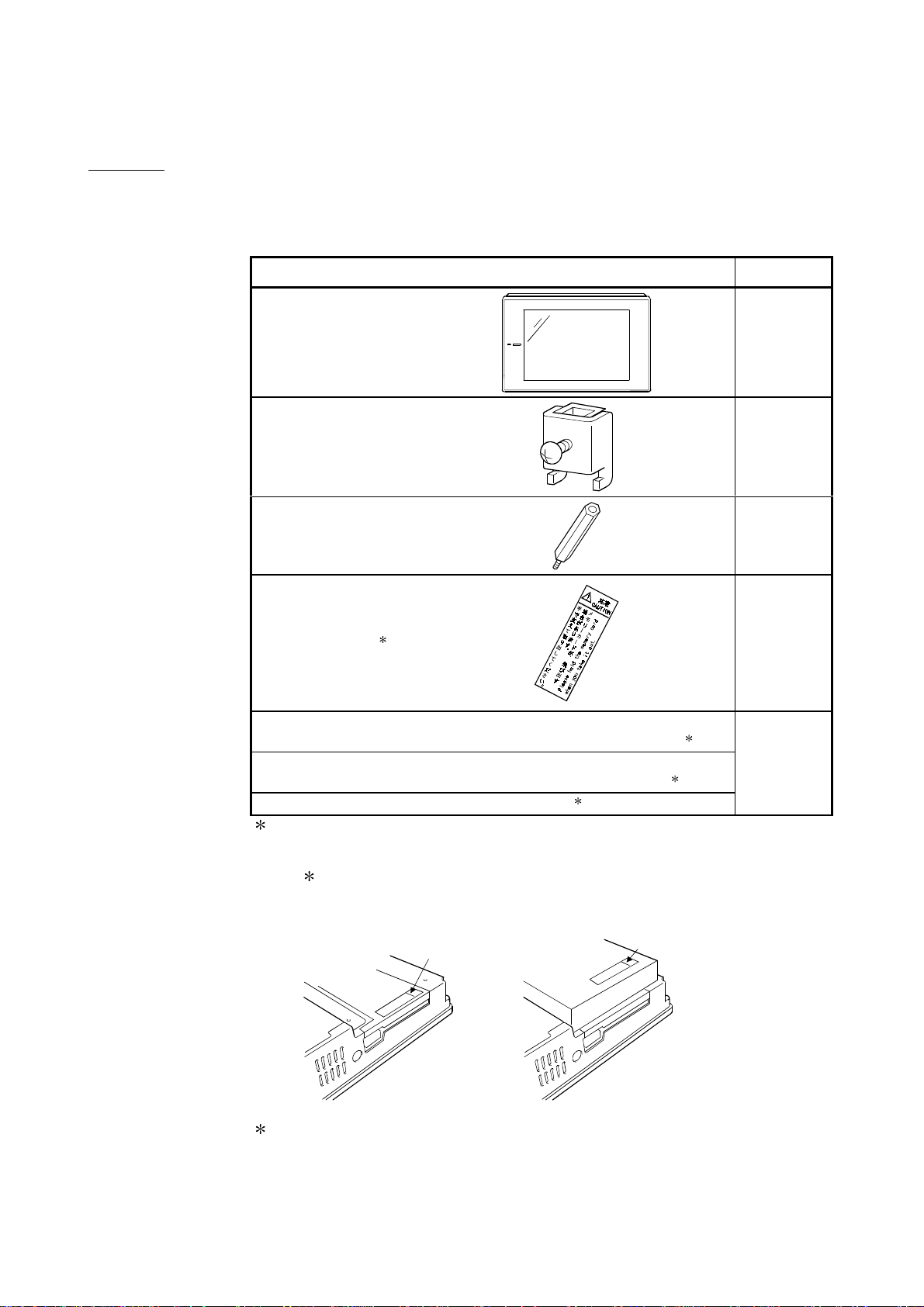
Print Date Manual Number Revision
Sep, 1998 SH(NA)-4005-A First edition
Feb, 1999 SH(NA)-4005-B
Addition
Section 1.1, 2.1, 2.2, 3.2, 3.3, 4.1, 4.2, 6.1, 6.3, 6.10, 6.11, 6.12, 6.13,
7.4, Appendix 1,2
A985GOT-TBA/TBD
Apr, 1999 SH(NA)-4005-C
Addition
Section 1.2, 1.3, 2.2, 3.2, 3.3, 6.1, 6.5, 7.4, 8.2, INDEX
A975GOT-TBA-B/TBD-B, A970GOT-TBA-B/TBD-B
A975GOT-TBA-EU, A970GOT-TBA-EU/SBA-EU, A960GOT-EBA-EU
Mar, 2000 SH(NA)-4005-D
Partial corrections
Section 2.1, 3.1, 6.1, 6.3, 6.5, 6.12, 7.4, Appendix 1, 2, 3
Partial additions
Section 2.2, 3.2, 3.3, 6.4, 6.6, 6.7
Addition
Section 2.3, 2.4, 6.14, 8.5
A985GOT-TBA-EU, A970GOT-LBA/LBD
Dec, 2000 SH(NA)-4005-E
Partial corrections
Chapter 5, Section 2.1, 2.3, 6.5, 6.7, 6.8, 6.9, 6.11, 6.12, 8.3
Partial additions
Chapter 1, Section 1.1, 2.2, 2.4, 3.2, 3.3, 4.1, 6.1, 6.3, 6.4, 6.6, 6.10, 7.4,
8.2, Appendix 1,2
Addition
Section 6.1.6, 6.1.7, 6.15, A985GOT-TBA-V, A985GOT-TBD-V
Jun, 2001 SH(NA)-4005-F
Partial corrections
Section 1.2.1, 2.3
Partial additions
Section 1.1, 1.2.2, 2.2, 3.2.1, 3.2.2, 3.2.3, 3.3.1,3.3.2, 4.2, 6.1.2, 6.1.3,
6.1.4, 6.5.3, 6.7.1, 6.14.2, 8.2, Appendix 2
Addition
Section 2.3.1, 2.3.2, 2.3.3, 2.3.4, 2.3.5
Feb, 2002 SH(NA)-4005-G
Partial corrections
SAFETY PRECAUT I O NS
Apr, 2002 SH(NA)-4005-H
Partial corrections
Section 2.3.3
Partial additions
Section 2.3.4, 2.3.5, 6.1.4, 8.2
Japanese Manual Version SH-3311-J
This manual does not warrant or license any industrial property rights and other rights. Under no circumstances will
Mitsubishi Electric be liable or responsible for any consequential problems involving the industrial property rights
which may arise as a result of the use of this equipment described in this manual.
1998 Mitsubishi Electric Corporation
A - 6 A - 6

INTRODUCTION
Thank you for choosing the Mitsubishi Graphic Operation Terminal.
Before using the equipment, please read this manual carefully to use the equipment to its optimum.
A copy of this manual should be forwarded to the end user.
CONTENTS
SAFETY INSTRUCTIONS.............................................................................................................................A- 1
About the manuals .........................................................................................................................................A-10
Abbreviations and generic terms in this manual ...........................................................................................A-11
Packing list......................................................................................................................................................A-13
1. OVERVIEW 1- 1 to 1- 9
1.1 Features ...................................................................................................................................................1- 2
1.2 Requirements to match EMC Directives .................................................................................................1- 4
1.2.1 EMC Directives..................................................................................................................................1- 4
1.2.2 Installation inside Control Box...........................................................................................................1- 5
1.2.3 Noise filter (power supply line filter)..................................................................................................1- 6
1.3 Requirements for compliance with the Low Voltage Directive............................................................... 1- 7
1.3.1 Standard applied for GOT.................................................................................................................1- 7
1.3.2 Power supply.....................................................................................................................................1- 7
1.3.3 Control cabinet ..................................................................................................................................1- 8
1.3.4 Grounding..........................................................................................................................................1- 8
1.3.5 External wiring...................................................................................................................................1- 9
2. SYSTEM CONFIGURATION 2- 1 to 2- 9
2.1 Overall Configuration ...............................................................................................................................2- 1
2.2 Component List........................................................................................................................................2- 2
2.3 Cautions on use of EMC command- and low voltage command-compatible products.........................2- 5
2.3.1 Caution points when using PC card/Flash PC card.........................................................................2- 5
2.3.2 About Modules that the EMC directive do not apply to....................................................................2- 5
2.3.3 Connection Format............................................................................................................................2- 6
2.3.4 When the communication module/board is used............................................................................. 2- 7
2.3.5 About the Cable Used.......................................................................................................................2- 7
2.4 Software packages to be used ................................................................................................................2- 8
2.5 Unusable Conventional Products............................................................................................................2- 8
2.6 Notes on Q4ARCPU Duplex System......................................................................................................2- 9
3. PERFORMA NCE 3- 1 to 3- 9
3.1 General Specifications.............................................................................................................................3- 1
3.2 Performance specifications......................................................................................................................3- 2
3.2.1 Performance specifications of the A985GOT(-V).............................................................................3- 2
3.2.2 Performance specifications of the A975GOT/A970GOT/A960GOT...............................................3- 6
3.2.3 Power supply specifications..............................................................................................................3- 8
3.3 Power Supply Power Consumed when Communication Board or Communication Module Is Fitted .. 3- 9
3.3.1 GOT with AC type input power supply .............................................................................................3- 9
3.3.2 GOT with DC type input power supply.............................................................................................3- 9
A - 7 A - 7

4. NAMES OF THE PARTS AND THEIR SETTINGS 4- 1 to 4- 4
4.1 Names of The Parts And Their Settings of the A985GOT(-V) ...............................................................4- 1
4.2 Names of The Parts And Their Settings of the A975GOT/A970GOT/A960GOT..................................4- 3
5. ROUGH PRE-OPERATION PROCEDURE 5- 1 to 5- 2
6. HANDLING 6- 1 to 6-35
6.1 GOT Main Unit .........................................................................................................................................6- 1
6.1.1 Handling instructions.........................................................................................................................6- 1
6.1.2 Installation method............................................................................................................................6- 3
6.1.3 Wiring method ...................................................................................................................................6- 5
6.1.4 Wiring precautions the part which matches the EMC Directives.....................................................6- 6
6.1.5 Human sensor (A985GOT(-V) only).................................................................................................6-15
6.1.6 Video input function (A985GOT-V only)...........................................................................................6-16
6.1.7 RGB input function (A985GOT-V only) ............................................................................................6-17
6.2 Slot Cover.................................................................................................................................................6-18
6.2.1 Mounting and dismounting procedures ............................................................................................6-18
6.3 Protective Sheet.......................................................................................................................................6-19
6.3.1 Protective sheet types.......................................................................................................................6-19
6.3.2 Mounting procedure ..........................................................................................................................6-19
6.4 Memory Board..........................................................................................................................................6-20
6.4.1 Memory board types .........................................................................................................................6-20
6.4.2 Mounting procedure ..........................................................................................................................6-20
6.5 PC Card....................................................................................................................................................6-21
6.5.1 PC card types....................................................................................................................................6-21
6.5.2 Battery changing timing and method................................................................................................6-22
6.5.3 Loading and unloading procedures.................................................................................................. 6-23
6.6 Communication Board .............................................................................................................................6-25
6.6.1 Connection board types....................................................................................................................6-25
6.6.2 Mounting procedure ..........................................................................................................................6-25
6.7 Communication Module...........................................................................................................................6-27
6.7.1 Connection module types .................................................................................................................6-27
6.7.2 Mounting procedure ..........................................................................................................................6-27
6.8 Printer .......................................................................................................................................................6-28
6.8.1 Printer types ......................................................................................................................................6-28
6.8.2 Connection procedure.......................................................................................................................6-28
6.9 Speech Output Device.............................................................................................................................6-29
6.9.1 Speech output device type................................................................................................................6-29
6.9.2 Connection procedure.......................................................................................................................6-29
6.10 Debug Stand ..........................................................................................................................................6-30
6.10.1 Debug stand types ..........................................................................................................................6-30
6.10.2 Mounting procedure........................................................................................................................ 6-30
A - 8 A - 8

6.11 Bar Code Reader...................................................................................................................................6-31
6.11.1 Bar code reader types.....................................................................................................................6-31
6.11.2 Connecting procedure.....................................................................................................................6-31
6.12 External I/O Module ...............................................................................................................................6-32
6.12.1 External I/O module type ................................................................................................................6-32
6.12.2 Mounting procedure........................................................................................................................6-32
6.13 CRT Display, TFT Display (A985GOT only).........................................................................................6-33
6.13.1 CRT Display, TFT Display types ....................................................................................................6-33
6.13.2 Connecting procedure.....................................................................................................................6-33
6.14 Attachment .............................................................................................................................................6-34
6.14.1 Attachment types.............................................................................................................................6-34
6.14.2 Mounting procedure........................................................................................................................ 6-34
6.15 Video/RGB Input Interface Module (A985GOT-V only)........................................................................6-35
6.15.1 Video/RGB input interface module types....................................................................................... 6-35
6.15.2 Mounting procedure........................................................................................................................6-35
7. MAINTENANCE AND INSPECTION 7- 1 to 7- 5
7.1 Instructions for Maintenance and Inspection ..........................................................................................7- 1
7.2 Daily Inspection........................................................................................................................................7- 2
7.3 Periodic Inspection...................................................................................................................................7- 2
7.4 Backlight for Liquid Crystal......................................................................................................................7- 3
7.4.1 How to change the backlight for liquid crystal..................................................................................7- 4
8. ERROR CODES AND ERROR MESSAGES 8- 1 to 8-16
8.1 Definition of the Error Codes and Messages Displayed......................................................................... 8- 1
8.2 Error Code and Error Message List.........................................................................................................8- 2
8.3 Precautions for use of flash PC card.......................................................................................................8- 6
8.4 Precautions for installation of ROM_BIOS..............................................................................................8- 7
8.5 Troubleshooting in bus connection.......................................................................................................... 8- 8
8.5.1 Locating error positions.....................................................................................................................8- 8
8.5.2 Further locating error positions.........................................................................................................8-13
8.5.3 Specific example of troubleshooting.................................................................................................8-14
8.6 Troubleshooting for monitoring................................................................................................................8-15
APPENDICES APP- 1 to APP- 9
Appendix 1 Outline Dimension Drawings................................................................................................APP- 1
Appendix 2 Depth at the Time of Communication Board/Communication Module Loading.................APP- 4
Appendix 3 Outline Dimension Drawings of Bus Connection Cables....................................................APP- 8
INDEX INDEX- 1 to INDEX- 2
A - 9 A - 9
About the manuals
The following manuals are related to this product.
Refer to the following list and request the required manuals.
Related Manuals
Manual name
GT Works Version5/GT Designer Version5 Operating Manual (Start up M anual)
Describes how to install GT Works Version 5/GT Designer Version 5 into a personal computer and how
to browse the online manuals.
(Found in the packing of the GT Works Version5/GT Designer Version5)
GOT900 Series Operating Manual (Introductory Manual)
For those who use the GOT for the first time, describes the way to create a monitor screen on GT
Designer, transfer monitor data to the GOT, and display it on the screen. (Available as option)
GT Works Version5/GT Designer Version5 Reference Manual
Deals with the system configuration of GT Works Version5/GT Designer Version5, the screen makeup of
the GT Designer, the general description of various monitoring functions, the procedure for displaying the
monitor screen on the GOT, and how to use the help function. (Available as option)
GOT-A900 Series User’s Manual (GT Works Version5/GT D esigner Version5 compati ble
Connection System Manual)
Gives the specifications, system configuration, setting method and connection diagram of each
connection form available for the GOT-A900 series. (Available as option)
GOT-A900 Series Operating Manual (GT Works Version5/GT Designer Version5 co mpatible
Extended • Option Functions Manual)
Provides the specifications of the utility, system monitoring, ladder monitoring, special function unit
monitoring, network monitoring functions and list editor functions available for the GOT-A900 series and
how to operate the dedicated monitor screen. (Available as option)
Manual number
(Model code)
IB-0800143
(13JU06)
SH-080116
(13JU07)
SH-080117
(13JF95)
SH-080119
(13JR20)
SH-080118
(13JU08)
GT Simulator Version5 Operating Manual
Explains the system configuration, screen makeup and using methods of GT Simulator.
(Available as option)
SH-080120
(13JU09)
A - 10 A - 10
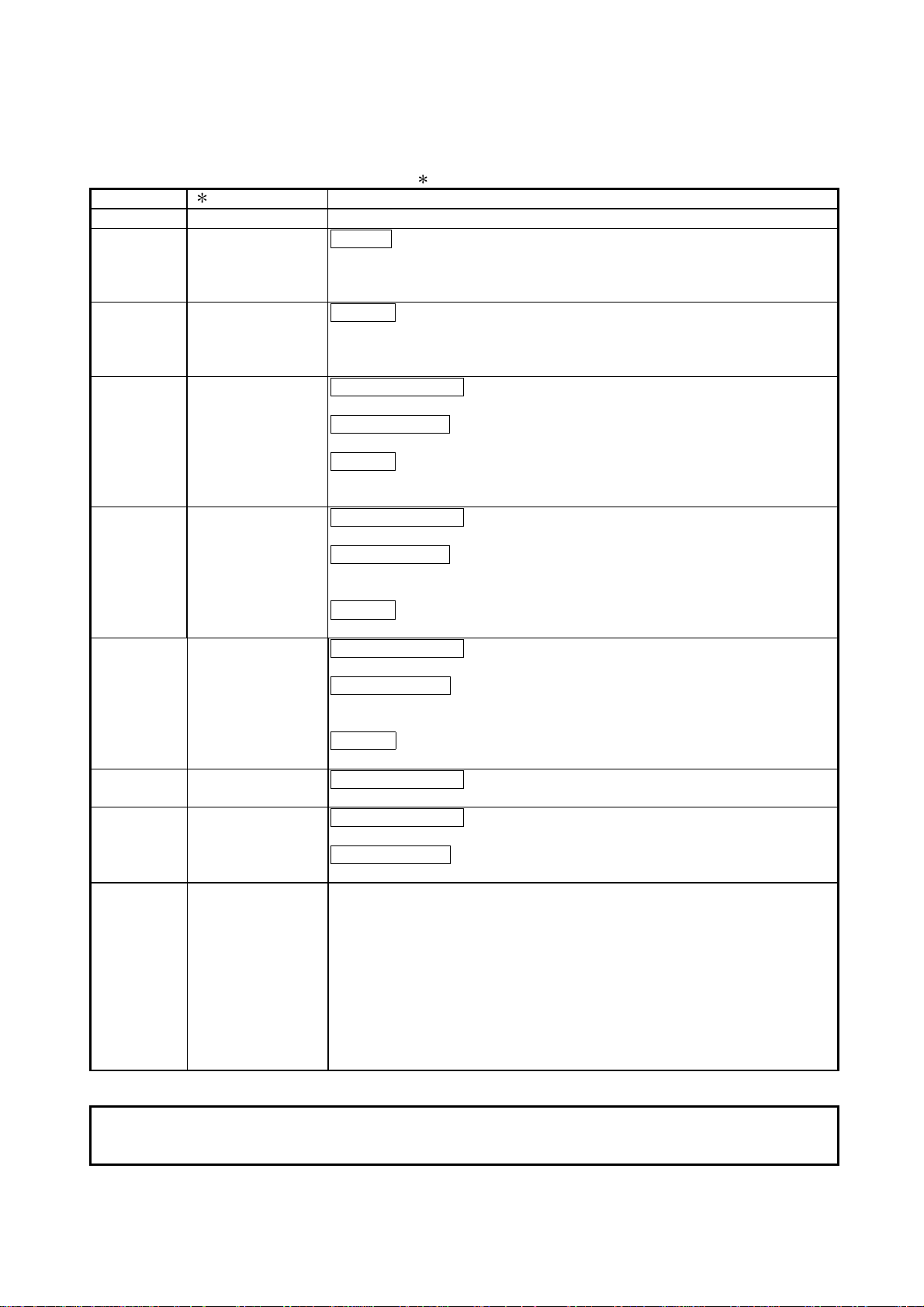
Abbreviations and generic terms in this manual
Abbreviations and generic terms used in this manual are described as follows:
Abbreviations and generic terms Description
A985GOT-V Generic term of A985GOT-TBA-V and A985GOT-TBD-V
GOT
Communication board
Communication unit
Option
Option unit
Software
A985GOT Generic term of A985GOT-TBA, A985GOT-TBD and A985GOT-TBA-EU
A975GOT
A970GOT
A97 GOT
A960GOT Generic term of A960GOT-EBA, A960GOT-EBD and A960GOT-EBA-EU
Bus connection
board
Serial
communication
board
Bus connection unit Gen e r i c t e r m of A 9 G T-BU S S U a nd A9 G T - B U S2SU
Data link unit Generic term of A7GT-J71AP23, A7GT-J71AR23 and A7GT-J71AT23B
Network unit Generic term of A7GT-J71LP23 and A7GT-J71BR13
CC-Link
communication unit
Ethernet
communication unit
Protection sheet
Backlight Abbreviation of A9GT-80LTT, A9GT-70LTTB, A9GT-70LTT and A9GT-70LTS type backlights
Debug stand Abbreviation of A9GT-80STAND and A9GT-70STAND type debug stand
PC card ( memory
card )
Memory board
Attachment Generic term of A77GT-96ATT/A87GT-96ATT/A87GT-97ATT attachments
Ten-key Panel Abbreviation of A8GT-TK ten-key Panel
A7GT-CNB Abbreviation of A7GT-CNB bus connector conversion box
A9GT-QCNB Abbreviation of A9GT-QCNB bus connector conversion box
External I/O unit Abbreviation of A9GT-70KBF type external I/O interface unit
Video input interface
unit
RGB input interface
unit
GT Works Ve rsion 5 Abbreviation of SW5D5C-GTWORKS-E software package
GT Designer
Version 5
GT Designer Abbreviation of image creation software GT Designer for GOT900
GT Simulator Abbreviation of GT Simulator screen simulator GOT900
GT Converter Abbreviation of data conversion software GT Converter for GOT900
GT Debugger Abbreviation of debugging software GT Debugger
GT Manager Abbreviation of GT Manager data editing software for GOT900
GT Developer Generic term of SW D5C-GPPW-E/SW D5F-GPPW-E software packages
GT Simulator
Generic term of A975GOT-TBA-B, A975GOT-TBD-B, A975GOT-TBA, A975GOT-TBD and
A975GOT-TBA-EU
Generic term of A970GOT-TBA-B A970GOT-TBD-B, A970GOT-TBA, A970GOT-TBD,
A970GOT-SBA, A970GOT-SBD, A970GOT-LBA, A970GOT-LBD, A970GOT-TBA-EU and
A970GOT-SBA-EU
Generic term of A975GOT and A970GOT
Generic term of A9GT-QBUSS, A9GT-QBUS2S, A9GT-BUSS and A9GT-BUS2S
Generic term of A9GT-RS4, A9GT-RS2 and A9GT-RS2T
Generic term of A8GT-J61BT13 and A8GT-J61BT15
Abbreviation of A9GT-J71E71-T
Abbreviation of A9GT-80PSC, A9GT-70PSC and A9GT-60PSC type transparent protection
sheets
Abbreviation of PC card with PCMCIA Ver.2.1
Abbreviation of A9GT-FNB, A9GT-FNB1M, A9GT-FNB2M, A9GT-FNB4M, A9GT-FNB8M,
A9GT-QFNB, A9GT-QFNB4M, A9GT-QFNB8M type option function memory board
Abbreviation of A9GT-80V4 type Video input interface unit
Abbreviation of A9GT-80R1 type RGB input interface unit
Generic term of SW5D5C-GOTR-PACKE software package and SW5D5C-GOTR-PACKEV
software package
Generic term of SW
LLT-E or later)
D5C-LLT-E ladder logic test tool function software package (SW5D5C-
A - 11 A - 11
Abbreviations and generic terms Description
QCPU (Q Mode)
Generic term of Q00JCPU, Q00CPU, Q01CPU, Q02CPU, Q02HCPU, Q06HCPU,
Q12HCPU and Q25HCPU CPU units
QCPU (A Mode) Generic term of Q02CPU-A, Q02HCPU-A and Q06HCPU-A CPU units
QCPU Generic term of QCPU (Q Mode) and QCPU (A Mode)
QnACPU (Large Type) Generic term of Q2ACPU, Q2ACPU-S1, Q3ACPU, Q4ACPU and Q4ARCPU CPU units
QnACPU (Small Type) Generic term of Q2ASCPU, Q2ASCPU-S1, Q2ASHCPU and Q2ASHCPU-S1 CPU units
QnACPU Generic term of QnACPU (Large Type) and QnACPU (Small Type)
AnUCPU Generic term of A2UCPU, A2UCPU-S1, A3UCPU and A4UCPU CPU units
AnACPU Generic term of A2ACPU, A2ACPU-S1 and A3ACPU CPU units
AnNCPU Generic term of A1NCPU, A2NCPU, A2NCPU-S1 and A3NCPU CPU units
CPU
ACPU (Large Type) Generic term of AnUCPU, AnACPU and AnNCPU CPU units
A2US(H)CPU Generic term of A2USCPU, A2USCPU-S1 and A2USHCPU-S1 CPU units
AnS(H)CPU Generic term of A1SCPU, A1SHCPU, A2SCPU and A2SHCPU CPU units
A1SJ(H)CPU Generic term of A1SJCPU-S3 and A1SJHCPU CPU units
ACPU (Small Type) Generic term of A2US(H)CPU, AnS(H)CPU and A1SJ(H)CPU CPU units
ACPU Generic term of ACPU (Large Type), ACPU (Small Type) and A1FXCPU CPU units
FXCPU
Motion controller CPU
Generic term of FX
2
series , FX
FX
0
2C
series, FX
series, FX
Generic term of A373UCPU, A373UCPU-S3, A273UCPU, A273UHCPU, A273UHCPU-S3,
A171SCPU-S3, A171SHCPU, A172SHCPU CPU unit
0N
2N
series, FX
series, FX
FA controller Generic term of LM610, LM7600, LM8000 CPU unit
GPP function
peripheral
connection unit
G4 Abbreviation of AJ65BT-G4-S3
E71 Generic term of AJ71E71-S3, A1SJ71E71-B2-S3 and A1SJ71E71-B5-S3
QE71 Generic term of AJ71QE71, A1SJ71QE71-B2, AJ71QE71-B5 and A1SJ71QE71-B5Ethernet unit
Q series-compatible E71 Generic term of QJ71E71, QJ71E71-B2 and QJ71E71-100
Omron PLC
Yasukawa PLC
SLC500 Series
Generic term of C200HS, C200H, C200H
C1000H,C2000H,CV500, CV1000, CV2000, CVM1-CPU11, CVM1-CPU21, CS1 CPU unit
Generic term of GL60S, GL60H, GL70H, GL120, GL130, CP-9200SH, CP-9300MS, MP-9 20,
MP-930, MP-940, CP-9200(H) and PROGIC-8 CPU unit
Generic term of SLC500-20, SLC500-30, SLC500-40, SLC5/01 SLC5/02, SLC5/03,
SLC5/04 SLC5/0 5
Generic term of 1761-L10BWA, 1761-L10BWB, 1761-L16AWA, 1761-L16BWA, 1761MicroLogix1000 Series
L16BWB, 1761-L16BBB, 1761-L32AWA, 1761-L32BWA, 1761-L32BWB, 1761-L32BBB,
1761-L32AAA, 1761-L20AWA-5A, 1761-L20BWA-5A, 1761-L20BWB-5A
MicroLogix1500 Series Abbreviation of 1764-LSP
Allen-Bradley PLC Generic term of SLC 500 Series, MicroLogix1000 Series, MicroLogix1500 Series
Generic term of JW-21CU, JW-22CU, JW-31CUH, JW-32CUH, JW-33CUH, JW-50CUH,
JW-70CUH, JW-100CUH CPU unit
Other PLC
Sharp PLC
PROSEC T Series Generic term of T3, T3H CPU unit
PROSEC V Series Abbreviation of Model3000 CPU unit
Toshiba PLC Generic term of PROSEC T Series and PROSEC V Series
SIEMENS PLC Generic term of SIMATIC S7-300 Series and SIMATIC S7-400 Series CPU unit
Large type H series
H200 to 252 Series
H Series board type
Generic term of H-302(CPU2-03H), H-702(CPU2-07H), H-1002(CPU2-10H), H-2002(CPU2-
20H), H-4010(CPU3-40H), H-300(CPU-03Ha), H-700(CPU-07Ha), H-2000(CPU-20Ha)
Generic term of H-200(CPU-02H, CPE-02H), H-250(CPU21-02H), H-252(CPU22-02H), H-
252B(CPU22-02HB), H-252C(CPU22-02HC, CPE22-02HC)
Generic term of H-20DR, H-28DR, H-40DR, H-64DR, H-20DT, H-28DT, H-40DT, H-64DT,
HL-40DR, HL-64DR
EH-150 Series Generic term of EH-CPU104, EH-CPU208, EH-CPU308, EH-CPU316
HITACHI PLC
(HIDIC H Serie s)
Matsushita Electric Works
PLC
Generic term of large type H series,H-200 to 252 Series H Series board type, EH-150 Series
Generic term of FP0-C16CT, FP0-C32CT, FP1-C24C, FP1-C40C, FP2, FP3, FP5, FP10(S),
FP10SH, FP-M(C20TC) and FP-M(C32TC)
Memory abbreviation of memory (flash memory) in the GOT
Others
OS Abbreviation of GO T system softwar e
Object Setting data for dynamic image
Personal Computer Personal computer where the corresponding software package is installed
0S
series, FX1 series, FX
2NC
series CPU unit
1N
series, FX
1S
series(C200HX, C200HG, C200HE), CQM1,
series,
A - 12 A - 12
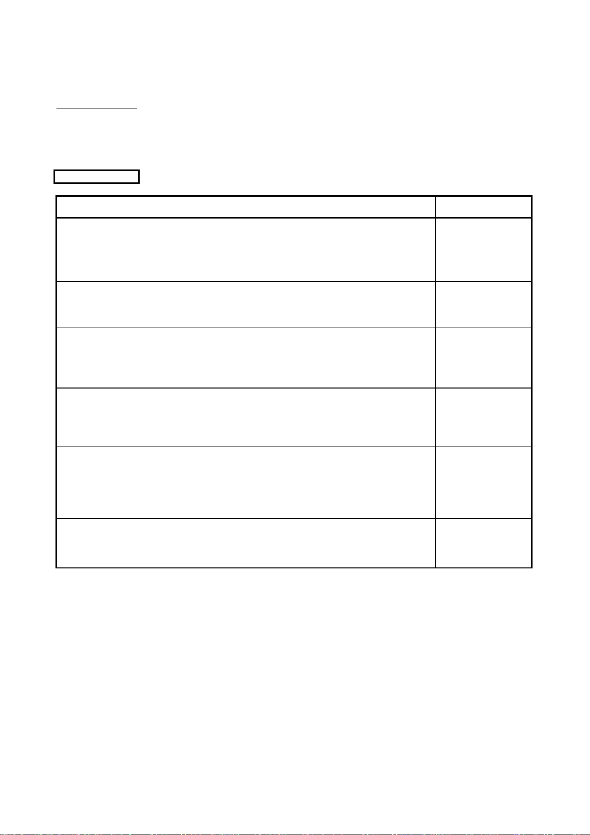
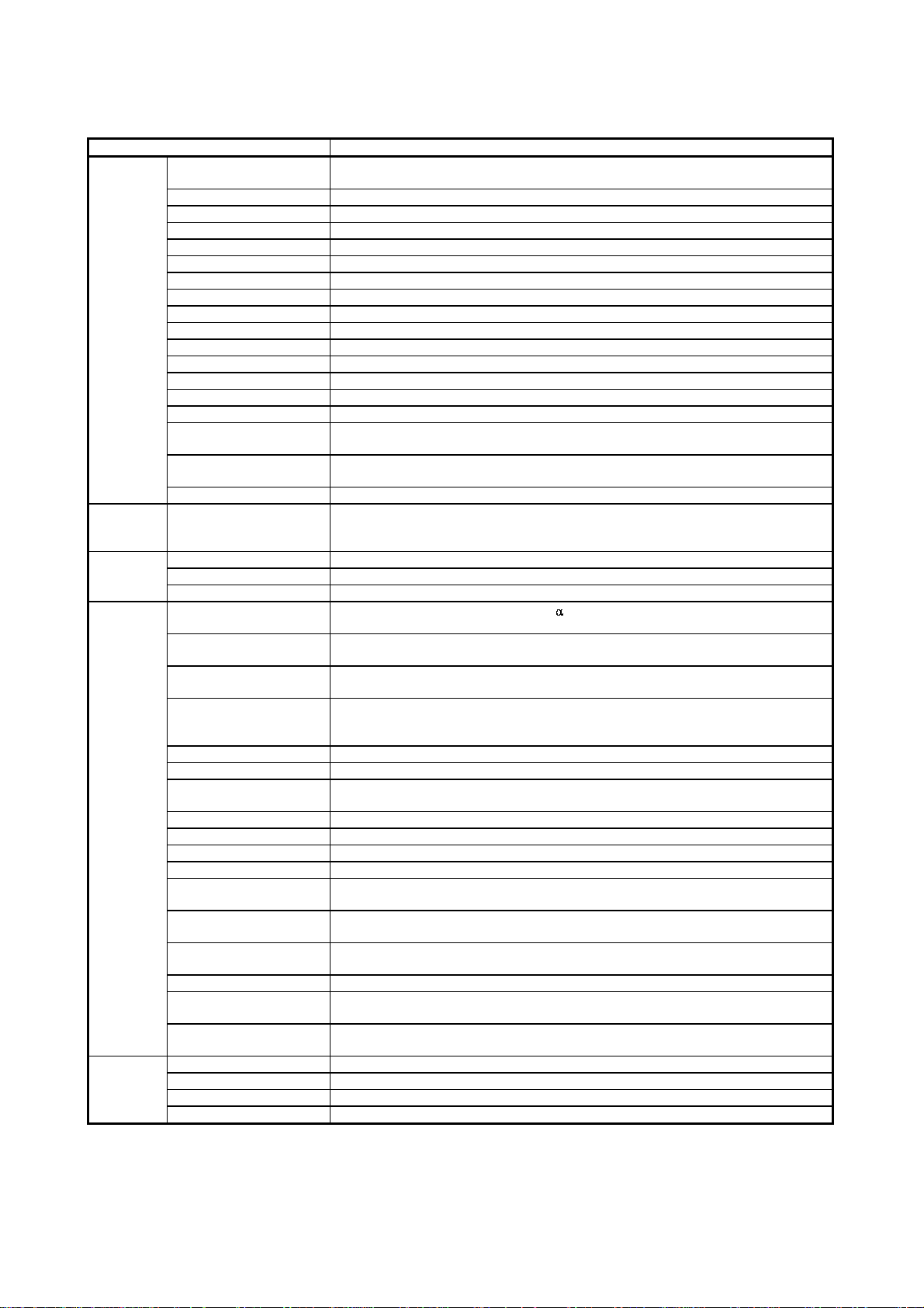
Packing list
e
After unpacking, confirm that you have received the following products.
Product Quantity
GOT main unit 1
Mounting fixture 4
Communication module
securing fixture
Caution plate (seal)
1
A975GOT-TBA/TBD(-B), A970GOT-TBA/TBD(-B), A970GOT-SBA/SBD,
A970GOT-LBA/LBD, A960GOT-EBA/EBD User's Manual (Hardware)
2
A985GOT-TBA-EU, A975GOT-TBA-EU, A970GOT-TBA-EU,
A970GOT-SBA-EU, A960GOT-EBA-EU User's Manual (Hardware)
A985GOT-TBA/TBD(-V) User's Manual (Hardware)
2
2
1 Affix a caution plate in a conspicuous position such as memory card interface part.
(Affix a caution plate on a communication module during its use.)
The caution plate is included only in the following GOT models.
A97 GOT
A960GOT
When affixing a coution plate on the
memory card interface
(except -EU):
(except -EU):
Caution plate
Hardware version L (jun., 2001) or later.
Hardware version H (jun., 2001) or later.
When affixing a coution plate on the
communication module
Caution plat
3
1
1
2 Changes with the GOT you purchased.
A - 13 A - 13
1 OVERVIEW
1 OVERVIEW
MELSEC-GOT
1
Type
A985GOT-TBA- V 100 to 240VAC
A985GOT-TBD- V 24VDC
A985GOT-TBA 100 to 240VAC
A985GOT-TBD 24VDC
A985GOT-TBA-EU 100 to 240VAC
A975GOT-TBA 100 to 240VAC
A975GOT-TBD 24VDC
A975GOT-TBA-B 100 to 240VAC
A975GOT-TBD-B 24VDC
A975GOT-TBA-EU 100 to 240VAC
A970GOT-TBA 100 to 240VAC
A970GOT-TBD 24VDC
A970GOT-TBA-B 100 to 240VAC
A970GOT-TBD-B 24VDC
A970GOT-TBA-EU 100 to 240VAC
A970GOT-SBA 100 to 240VAC
A970GOT-SBD 24VDC
A970GOT-SBA-EU 100 to 240VAC
A970GOT-LBA 100 to 240VAC
A970GOT-LBD 24VDC
A960GOT-EBA 100 to 240VAC
A960GOT-EBD 24VDC
A960GOT-EBA-EU 100 to 240VAC
This user's manual explains the specifications, handling and other information of the
GOT-A900 series graphic operation terminal module (abbreviated to the GOT).
The GOT can be used as an electronic operator panel which has achieved on its
monitor screen the switch operation, lamp indication, data display, message display
and other operations which were previously performed on an operator panel.
The following GOT ty pe s are available.
Rough Specifications
Power supply type Display color [Color] Display section Resolution [Dots] Screen size [cm]
256
(During image
display: 65536)
256
16
8 D-STN color liquid crystal
2
(Monochrome)
2
(Yellow orange,
black)
High luminance TFT color
liquid crystal
Wide viewing angle
TFT color liquid crystal
High luminance
TFT color liquid crystal
Wide viewing angle
TFT color liquid crystal
High luminance
TFT color liquid crystal
STN monochrome liquid
crystal
High-luminance EL 640 × 400 23 (9inch)
800 × 600 31 (12inch)
640 × 480 26 (10inch)
1 - 1 1 - 1
1 OVERVIEW
1.1 Features
MELSEC-GOT
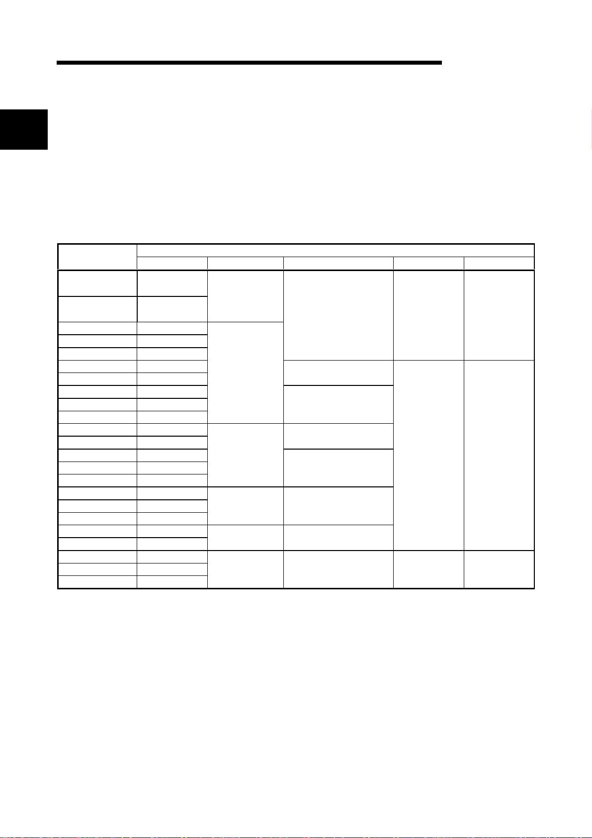
(1) Compact display device in pursui t of mounting, outline dimensions
and thinness
With the display screen size identical to that of the conventional type, the outline
dimensions and depth are substantially reduced to achieve a compact size and
thin design.
The GOT is designed to connect cables at its bottom to ensure that extra space
is not needed for the connectors and bending of the cables when the GOT is
mounted on a control box or the like.
A870GOT
A970GOT
A870GOT
A970GOT
(2) User-friendly multi media di spl ay device
Clear, high-grade display has been achieved by 256-color representation.
(A975GOT, A985GOT(-V) only)
Ear-appealing information transmission has also been achieved by supporting
speech output using the Windows WAV file.
1
ine 1 stopped!
(3) Fast data transfer of OS and screen data by memor y car d
The PC card for OS and screen data can be created easily on a personal
computer. By load in g the crea te d ca rd in to th e GOT, y ou can e xchan ge the OS
and screen data rapidly. (RS-232C data transfer can also be made as
conventionally.)
Commercially available PC card
(Compliant with PCMCIA Ver.2.1)
1 - 2 1 - 2

1 OVERVIEW
MELSEC-GOT
(4) Compatible with a wide var i ety of connection forms
The GOT is compatible with various connection forms such as the MELSEC and
computer link connections, including the bus connection which permits fast
communication. You can choose the connection form matching the system.
(5) Heavy-duty body usable in rig or ous envi r onment and oper ation
The display section of the GOT complies with the IP65F, IP67F and NEMA4
Waterproof, Dustproof Standard and is usable in a wide range of environment.
(6) Maintenance function further enhanced in a f finity wi th PLC
• Supporting the factor search mode which searches for the contact of a failure
factor at the device search time in the ladder monitoring function, the GOT has
shortened the fai lu r e fa cto r analysis time.
• Upgraded alarm history function
The GOT can support the failure occurrence counting function, cumulative
failure time totalizing function and history printing function, and start ladder
monitoring wi th the cor respo nd in g de vi ce sea rch ed wit h a singl e key st ro ke at
the failure detail display time.
(7) Improvement of safety by upgraded secur i ty function
• Supporting the operation protective function using up to 16 levels of passwords,
the GOT can hide the display or disable input operation according to the
password level. You can achieve hidden screens and hidden operations and
easily change th e di splay data per GOT used.
• You can specify the time delay function (ON delay/OFF delay) of the touch
switches, double-pushing switches and interlock conditions to reduce
malfunctions due to wrong key pushing.
(8) Energy saving mode using human sensor ( A985GOT(- V) onl y)
• The human sensor detects operators in the sensor detection area and turns the
backlight ON/OFF automatically.
The backlight can be turned off automatically if no operator motions are not
detected for a given period of time. (This time can be set by the user.)
1 - 3 1 - 3
1 OVERVIEW
1.2 Requirements to match EMC Directives
EMC Directives which are among European Directives become forced.
EMC Directives are those which require "any strong electromagnetic force is not output
to the external.: Emission (electromagnetic interference)" and "It is influenced by the
electromagnetic wave from the external.: Immunity (electromagnetic sensitivity)".
Items 1.2.1 thru 1.2.3 summarize the precautions to use GOT and configure the
mechanical unit in order to match the EMC directives.
Though the data described herein are produced with our best on the basis of the
requirement items and standards of the restrictions gathered by Mitsubishi, they do not
completely guaranteed that all mechanical unit manufactured according to the data do
not always match the above directives. The manufacturer itself which manufactures
the mechanical unit must finally judge the method and others to match the EMC
directives.
1.2.1 EMC Directives
The standards of the EMC Directives are shown below.
Specifications Test Item Test Description Standard Values
EN55011
Radiated noise
EN50081-2:
1995
EN55011
Conduction noise
EN61000-4-2
Static electricity immunity
EN61000-4-4
First transient burst noise
ENV50140
EN50082-2:
1995
Radiated electromagnetic
field AM modulation
ENV50204
Radiated electromagnetic
field Pulse modulation
ENV50141
Conduction noise
MELSEC-GOT
30M-230MHz QP :
30dBµ V/m (30m
2
2
2
Measure the emission released by
the product.
Measure the emission released by
the product to the power line.
Immunity test by applying static
2
electricity to the module enclosure.
Immunity test by applying burst
noise to the power line and signal
2
cable., 2kV
Immunity test by applying
aradiated electric field to the
2
product.
Immunity test by applying
aradiated electric field to the
2
product.
Immunity test by inducting an
electromagnetic field in the power
line signal cable.
measurement)
230M-1000MHz QP :
37dBµ V/m (30 m
measurement)
150K-500kHzQP:
79dB, Mean : 66dB
500K-30MHz QP :
73dB, Mean: 60dB
±4kV contact discharge
±8kV air discharge
±2kV
10V/m, 80-1000MHz,
80% AM modulation @
1kHz
10V/m, 900MHz, 200Hz
pulse modulation, 50%
duty
10Vrms, 0.15-80MHz,
80% modulation @ 1kHz
1
1
1 QP: Quasi-peak value, Mean: Average value
2 The GOT is an open ty pe dev ice (device insta lle d t o a not he r device) and must be
installed in a conductive control pauel or cabinet.
About these test items, install the control panel, combine with a PLC from this
company, and run a test.
1 - 4 1 - 4

1 OVERVIEW
1.2.2 Installation inside Control Box
The GOT is an open type device (device installed to another device) and must be
installed in a conductive control pauel or cabinet.
It not only assu re th e sa fe ty but al so ha s a la r ge effect t o shut dow n the noi se
generated from GOT, on the control panel.
1) Control cabinet
a) Use a conductive control cabinet.
b) When attaching the control cabinet's top plate or base plate, mask painting
and weld so that good surface contact can be made between the cabinet and
plate.
c) To ensure good electrical contact with the control cabinet, mask the paint on
the installation bolts of the inner plate in the control cabinet so that contact
between surfaces can be ensured over the widest possible area.
MELSEC-GOT
d) Earth the control cabinet with a thick wire so that a low impedance connection
to ground can be ensured even at high frequencies. (22mm
recommended.)
e) Holes made in the control cabinet must be 10cm (3.94in.) diameter or less. If
the holes are 10cm (3.94in.) or larger, radio frequency noise may be emitted.
In addition, because radio waves leak through a clearance between the
control panel door and the main unit, reduce the clearance as much as
practicable.
The leakage of radio waves can be suppressed by the direct application of an
EMI gasket on the paint surface.
Our tests have been ca rri ed out on a pan el havi ng th e da mping cha ra c ter i sti cs
of 37 dB max. and 30 dB mean (mea s u red by 3 m meth o d wi th 30 to 300
MHz).
2
wire or thicker is
2) Connection of power and ground w i r es
Ground and power supply wires for the GOT must be connected as described
below.
a) Provide an earthing point near the GOT. Earth the power supply's LG and FG
terminals (LG : Line Ground, FG : Frame Ground) with the thickest and
shortest wire possible. (The wire length must be 30cm (11.18in.) or shorter.)
The LG and FG terminals function is to pass the noise generated in the PC
system to the ground, so an impedance that is as low as possible must be
ensured. As the wires are used to relieve the noise, the wire itself carries a
large noise content and thus short wiring means that the wire is prevented
from acting as an antenna.
Note) A long condu ct o r will be come a more e ffi cie nt an t enn a at hig h
frequency.
b) The earth wire led from the earthing point must be twisted with the power
supply wires. By twisting with the earthing wire, noise flowing from the power
supply wires can be relieved to the earthing. However, if a filter is installed on
the power supply wires, the wires and the earthing wire may not need to be
twisted.
1 - 5 1 - 5
1 OVERVIEW
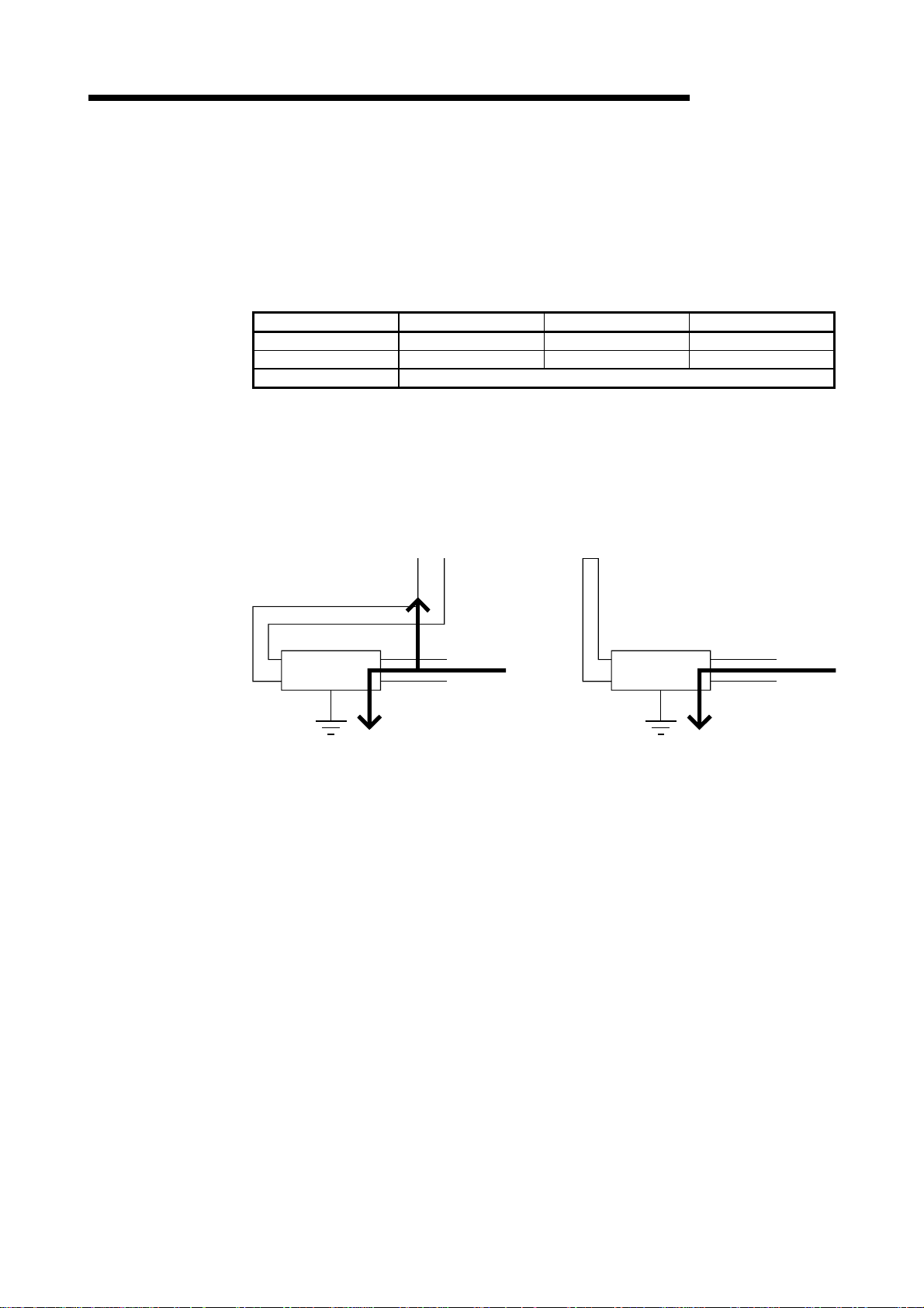
1.2.3 Noise filter (power supply line filter)
The noise filter (power supply line filter) is a device effective to reduce conducted
noise. Except some models, installation of a noise filter onto the power supply lines is
not necessary. However co ndu cted noi se can be redu ce d if i t is inst all ed. (The no i se
filter is generally effective for reducing conducted noise in the band of 10MHz or less.)
Usage of the following filters is recommended.
Model name FN343-3/01 FN660-6/06 ZHC2203-11
Manufacturer SCHAFFNER SCHAFFNER TDK
Rated current 3A 6A 3A
Rated voltage 250V
The precautions required when installing a noise filter are described below.
1) Do not bundle the wires on the input side and output side of the noise filter. When
bundled, the output side noise will be induced into the input side wires from which
the noise was fil ter ed .
MELSEC-GOT
Input side
(power supply side)
Induction
Filter
Output side
(device side)
a) The noise will be included when the input and
output wires are bundled.
Input side
(power supply side)
Filter
Output side
(device side)
b) Separate and lay the input and output wires.
2) Earth the noise filter earthing terminal to the control cabinet with the shortest wire
possible (appro x. 10 cm (3.9 4 in . )).
1 - 6 1 - 6
1 OVERVIEW
1.3 Requirements for compliance w i th the Low Voltage Directive
The Low Voltage Directive is mandatory within Europe, effective 1st January 1997.
The Low Voltage Directive requires each device which operates with power supply
ranging from 50VAC to 1000V and 75VDC to 1500V to satisfy necessary safety items.
In the Sections from 1.3.1 to 1.3.5, cautions on installation and wiring of the GOT to
conform to the Low Voltage Directive requires are described.
We have put the maximum effort to develop this material based on the requirements
and standards of the Directive that we have collected. However, compatibility of the
devices which are fabricated according to the contents of this manual to the above
Directive is not guaranteed. Each manufacturer who fabricates such device should
make the final judgement about the application method of the Low Voltage Directive
and the product compatibility.
1.3.1 Standard applied for GOT
The standard applied for GOT is EN61010-1 safety of devices used in measurement
rooms, control rooms, or laboratories.
MELSEC-GOT
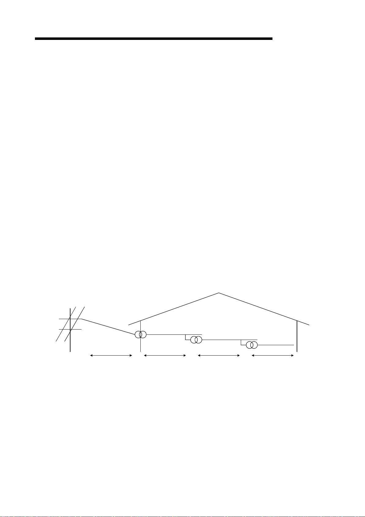
1.3.2 Power supply
The insulation specification of the GOT was designed assuming installation category II.
Be sure to use the installation category II power supply to the GOT.
The installation category indicates the durability level against surge voltage generated
by lightning strike. Category I has the lowest durability; category IV has the highest
durability.
Category ICategory IICategory IIICategory IV
Installation Category
Category II in di cat e s a pow e r supply whose voltag e ha s bee n re du ced by tw o or more
levels of isolating transformers from the public power distribution.
1 - 7 1 - 7

1 OVERVIEW
1.3.3 Control cabinet
MELSEC-GOT
Because the GOT is op en t y pe equi p men t (a devi ce de si gne d to be sto red wi th in
another module), be sure to use it only when installed in a control cabinet.
1) Electrical shock prevention
In order to such as the operators from electric shocks, the control box must have
the followin g fun c ti on s :
a) The control cabi ne t must be equ ipp ed wi th a lo ck so t ha t only skilled or
qualified personnel.
b) The control cabinet must be fitted with advice which automatically stops the
power supply when the cabinet is opened.
2) Dustproof and waterproof features
The control cabinet also provides protection from dust, water and ether
substances. Insufficient ingression protection may lower the insulation withstand
voltage, resulting in insulation destruction. The insulation in our GOT is designed
to cope with the pollution level 2, so use in an environment with pollustion level 2
or better.
Pollution level 1 : An environment where the air is dry and conductive dust
does not exist.
Pollution level 2 : An environment where conductive dust does not usually
exist, but occasional temporary conductivity occurs due to
the accumulated dust.
Generally , this is the level for in si d e th e co nt rol bo x
equivalent a control room or on the floor of a typical factory.
Pollution level 3 : An environment where conductive dust exits and
conductivity may be generated due to the accumulated
dust.
An environment for a typical factory floor.
Pollution level 4 : Continuous conductivity may occur due to rain, snow, etc.
An outdoor environment.
1.3.4 Grounding
There are two kin d s of g r ounding terminals a s show n be l ow . Bo th ter min al s must be
grounded.
Be sure to ground the grounding for the safety reasons and EMC Directives.
Protective g roun ding
Functional grounding
1 - 8 1 - 8
:
Maintains the safety of the GOT and improves the noise
resistance.
:
Improves the noise resistance.
1 OVERVIEW
1.3.5 External wiring
MELSEC-GOT
1) External devices
When a device with a hazardous voltage circuit is externally connected to the
PC, select a model which complies with the Low Voltage Directive's requirements
for isolation between the primary and secondary circuits.
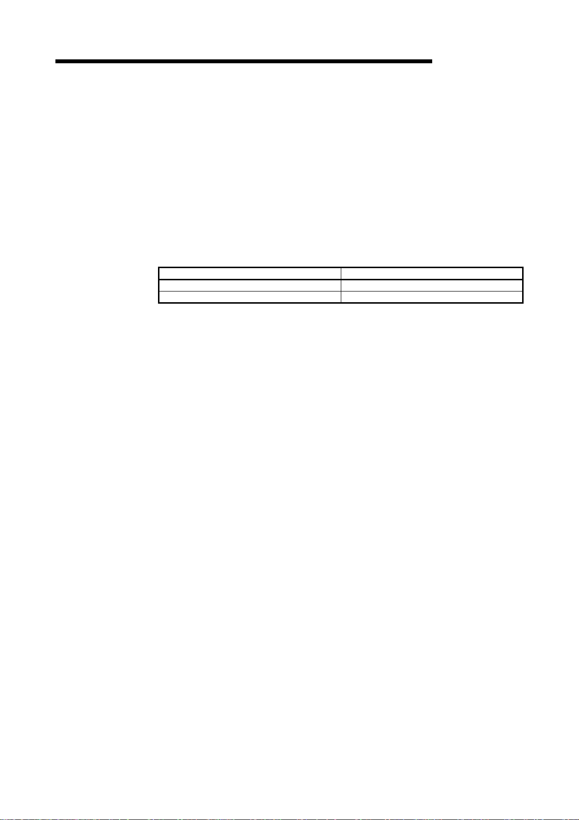
2) Insulation requirements
Dielectric withstand voltages are shown in the following table.
Intensive Insulation Withstand Voltage
(Installation Category II, source : IEC664)
Rated voltage of hazardous voltage area Surge withstand voltage (1.2/50 µs)
150 VAC or below 2500V
300 VAC or below 4000V
1 - 9 1 - 9
2 SYSTEM CONFIGURATION
2 SYSTEM CONFIGURATION
This chapter explains the system configuration of the GOT.
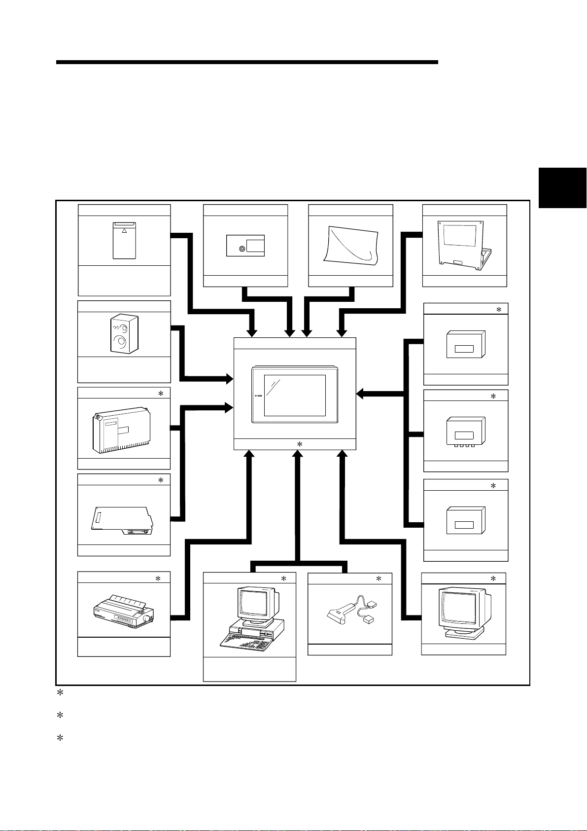
2.1 Overall Configuration
MELSEC-GOT
PC card (Memeory card)
Commercially available
Based on JEIDA Ver4.2
(Based on PCMCIA2.1)
Speech output device
Commercially available
(Compatible with stereo
mini-jack)
Communication module
e.g. A7GT-J71AP23
Communic ation board
The overall configuration of the GOT is shown below.
Memory board
e.g. A9GT-FNB
GOT
1
A985GOT(-V)/A97 GOT/A960GOT
1
Protective sheet
e.g. A9GT-70PSC
Debug stand
e.g. A9GT-70STAND
External I/O module
A9GT-70KBF
Video input unit
A9GT-80V4
RGB input unit
2
1
1
1
e.g. A9GT-BUSS
Pinter
Commercially available
Window compatible printer
Personal computer
Commercially available
(Compatible with Windows 95,
Windows 98, Windows N T4.0
2 1 31
Bar code reader
OPT-5125-RS1232C(H)
A9GT-80R1
CRT
Commercially available
1 For details of the system configuration, refer to the [GOT-A900 Series User's Manual (GT Works
Version5/GT Designer Version5 compatible Connection System Manual)].
2 For details of the system configuration, refer to the [GT Works Version5/GT Designer Version5 Reference
Manual].
3 Only the A985GOT may be connected to the CRT. (A985GOT-V can not be used.)
2 - 1 2 - 1
2 SYSTEM CONFIGURATION
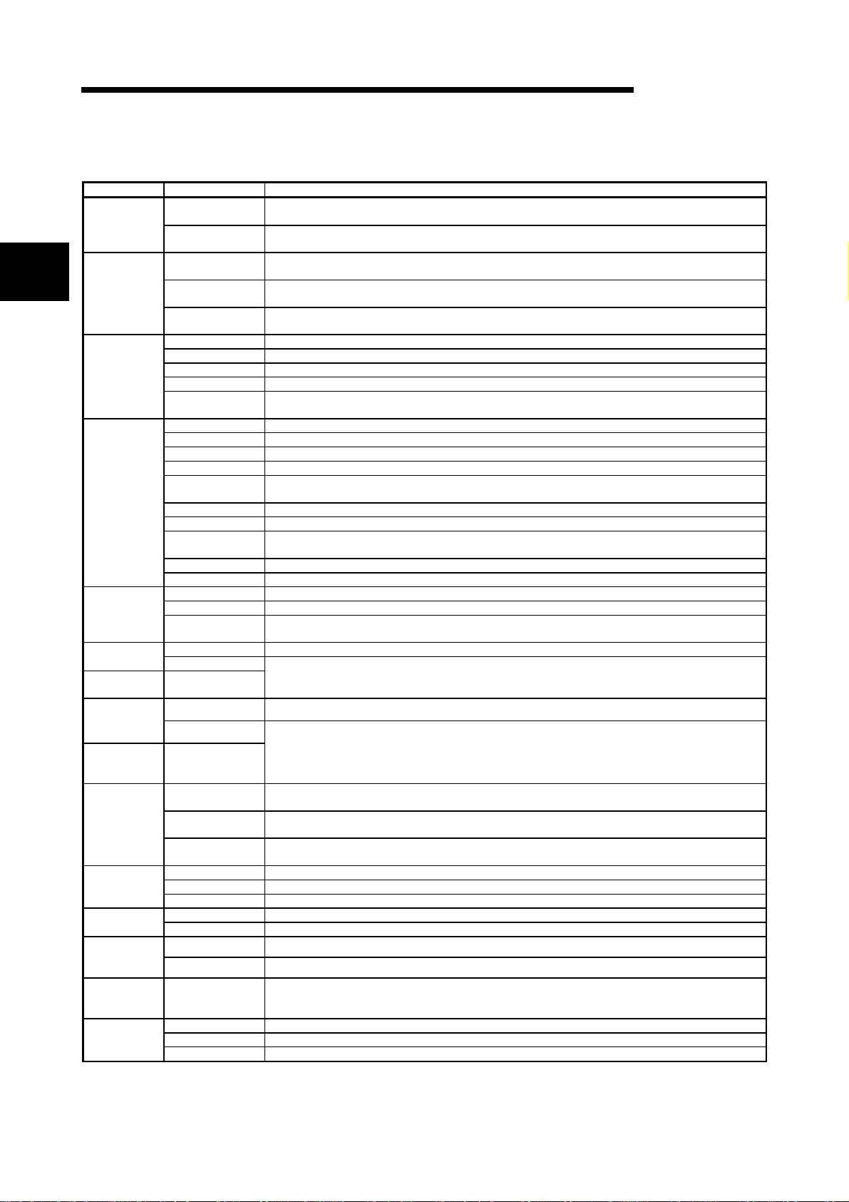
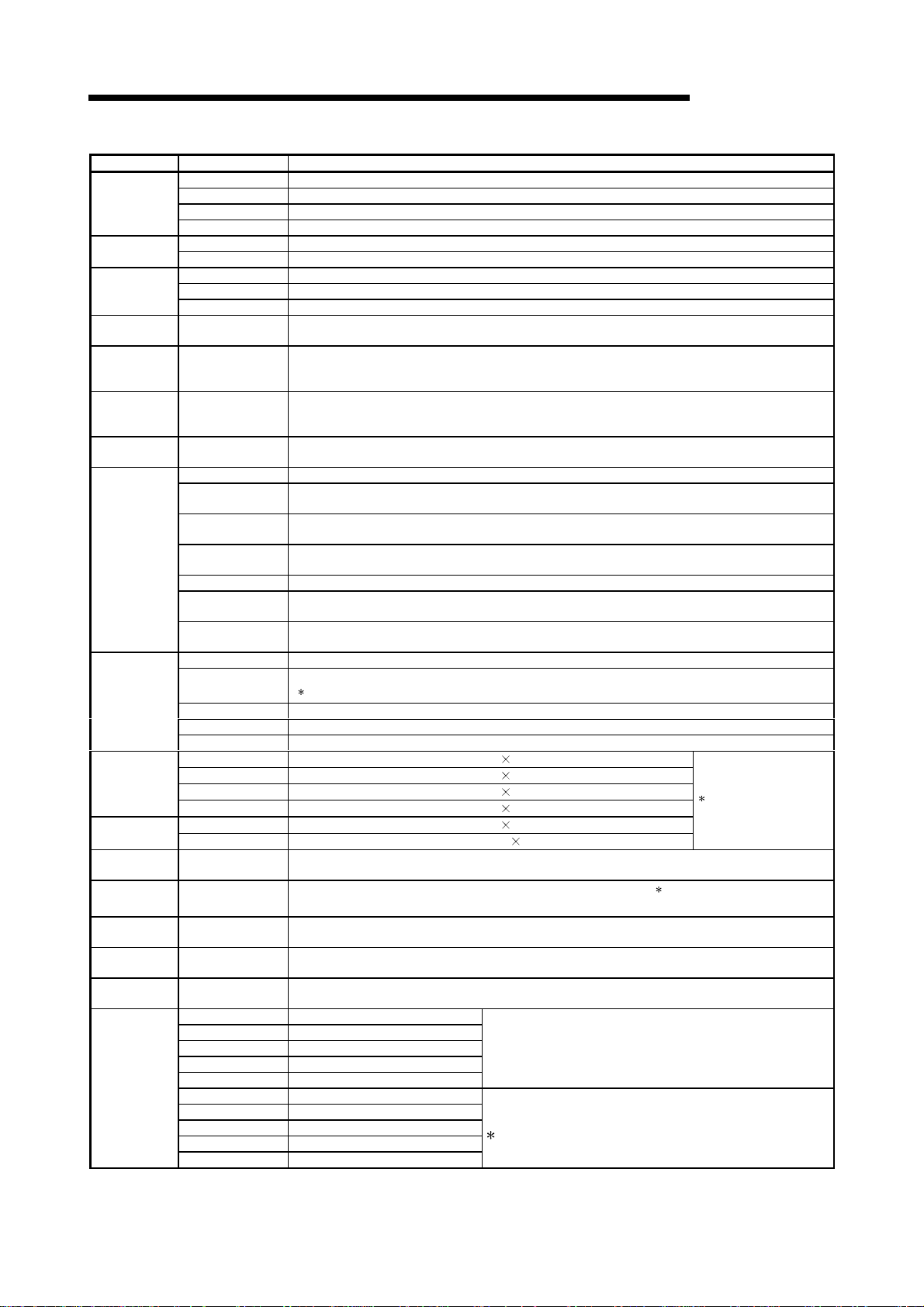
2.2 Component List
Component Type Remarks
A985GOT-V
2
A985GOT
A975GOT
A970GOT
A960GOT
Bus connection
board
Bus connection
module
Multidrop bus
connection
board
Multidrop bus
connection
module
Serial
communication
board
Data link
module
Network
module
CC-Link
communication
module
Ethernet
communication
module
Protective
sheet
A985GOT-TBA-V
A985GOT-TBD-V
A985GOT-TBA
A985GOT-TBD
A985GOT-TBA-EU
A975GOT-TBA 26cm (10inch), 256 color display, wide viewing angle TFT color liquid crystal, 100 to 240VAC
A975GOT-TBD 26cm (10inch), 256 color display, wide viewing angle TFT color liquid crystal, 24VDC
A975GOT-TBA-B 26cm (10inch), 256 color display, high-luminance TFT color liquid crystal, 100 to 240VAC
A975GOT-TBD-B 26cm (10inch), 256 color display, high-luminance TFT color liquid crystal, 24VDC
A975GOT-TBA-EU
A970GOT-TBA 26cm (10inch), 16 color display, wide viewing angle TFT color liquid crystal, 100 to 240VAC
A970GOT-TBD 26cm (10inch), 16 color display, wide viewing angle TFT color liquid crystal, 24VDC
A970GOT-TBA-B 26cm (10inch), 16 color display, high-luminance TFT color liquid crystal, 100 to 240VAC
A970GOT-TBD-B 26cm (10inch), 16 color display, high-luminance TFT color liquid crystal, 24VDC
A970GOT-TBA-EU
A970GOT-SBA 26cm (10inch), 8 color display, D-STN color liquid crystal, 100 to 240VAC
A970GOT-SBD 26cm (10inch), 8 color display, D-STN color liquid crystal, 24VDC
A970GOT-SBA-EU
A970GOT-LBA 26cm (10inch), STN monochrome liquid crystal, 100 to 240VAC
A970GOT-LBD 26cm (10inch), STN monochrome liquid crystal, 24VDC
A960GOT-EBA 23cm (9inch), 2 color display, high-luminance EL, 100 to 240VAC
A960GOT-EBD 23cm (9inch), 2 color display, high-luminance EL, 24VDC
A960GOT-EBA-EU
A9GT-QBUSS For bus connection, small connector type (For QCPU (Q mode))
A9GT-BUSS
A9GT-BUSSU
A9GT-QBUS2S For multidrop bus connection, small connector type (For QCPU (Q mode))
A9GT-BUS2S
A9GT-BUS2SU
A9GT-RS4
A9GT-RS2
A9GT-RS2T
A7GT-J71AP23 For MELSECNET(II) optical link connection, for use as local station
A7GT-J71AR23 For MELSECNET(II) coaxial link connection, for use as local station
A7GT-J71AT23B For MELSECNET/B connection, for use as local station
A7GT-J71LP23 For MELSECNET/10 optical loop network connection, for use as ordinary station
A7GT-J71BR13 For MELSECNET/10 coaxial bus network connection, for use as ordinary station
A8GT-J61BT13 For CC-Link connection, for use as intelligent device station
A8GT-J61BT15 For CC-Link connection, for use as remote device station
A9GT-J71E71-T For Ethernet connection
A9GT-80PSC Transparent protective sheet for A985GOT(-V), MITSUBISHI logotype can be removed.
A9GT-70PSC Transparent protective sheet for A975/970GOT, MITSUBISHI logotype can be removed.
A9GT-60PSC Transparent protective sheet for A960GOT, MITSUBISHI logotype can be removed.
MELSEC-GOT
31cm (12inch), 256 color display, high-luminance TFT color liquid crystal, 100 to 240VAC,
Video/RGB display supports
31cm (12inch), 256 color display, high-luminance TFT color liquid crystal, 24VDC, Video/RGB display
supports
31cm (12inch), 256 color display, high-luminance TFT color liquid crystal, 100 to 240VAC, built-in
CRT interface
31cm (12inch), 256 color display, high-luminance TFT color liquid crystal, 24VDC, built-in CRT
interface
31cm (12inch), 256 color display, high-luminance TFT color liquid crystal, 100 to 240VAC, built-in
CRT interface, EMC Directive and Low Voltage Directive compliant product
26cm (10inch), 256 color display, high-luminance TFT color liquid crystal, 100 to 240VAC,
EMC Directive and Low Voltage Directive compliant product
26cm (10inch), 16 color display, high-luminance TFT color liquid crystal, 100 to 240VAC,
EMC Directive and Low Voltage Directive compliant product
26cm (10inch), 8 color display, D-STN color liquid crystal, 100 to 240VAC,
EMC Directive and Low Voltage Directive compliant product
23cm (9inch), 2 color display, high-luminance EL, 100 to 240VAC,
EMC Directive and Low Voltage Directive compliant product
For bus connection, small connector type (For A/QnA/Motion controller CPU)
For multidrop bus connection, small connector type (For A/QnA/Motion controller CPU)
For Direct connection to CPU/Computer link connection/Microcomputer connection and RS-422
connection (Without clock function)
For Direct connection to CPU/Computer link connection/Microcomputer connection and RS-232C
connection (Without clock function)
For Direct connection to CPU/Computer link connection/Microcomputer connection and RS-232C
connection (Incorporating clock function)
2 - 2 2 - 2
2 SYSTEM CONFIGURATION
Component Type Remarks
A9GT-80LLT Backlight for A985GOT(-V)
Backlight
Debug stand
Attachment
External I/O
module
Video input
interface
module
RGB input
interface
module
Numeric
keypad panel
Memory board
PC card/
memory card
CRT display
TFT display
Bar code
reader
Printer —
Speech output
device
Bus extension
connector box
Bus connector
conversion box
Bus connection
cable QCPU
(Q mode)
A9GT-70LTT Backlight for A975/970GOT wide viewing angle TFT color liquid crystal type
A9GT-70LTTB Backlight for A975/970GOT high-luminance TFT color liquid crystal type
A9GT-70LTS Backlight for A970GOT D-STN color/monochrome liquid crystal type
A9GT-80STAND Debug stand for A985GOT(-V)
A9GT-70STAND Debug stand for A975/970/960GOT
A77GT-96ATT Attachment used for replacement from A77GOT to A960GOT
A87GT-96ATT Attachment used for replacement from A870GOT to A960GOT
A87GT-97ATT Attachment used for replacement from A870GOT to A975/970GOT
A9GT-70KBF For external I/O equipment connection
A9GT-80V4 For video camera connection
A9GT-80R1 For personal computer connection
A8GT-TK Data entry Numeric Keypad Panel
A9GT-FNB Exclusively used for optional OS storage (MELSEC-A/FX Ladder monitor-compatible)
A9GT-FNB2M
A9GT-FNB4M
A9GT-FNB8M
A9GT-QFNB Exclusively used for optional Os storage (MELSEC-Q/QnA/A/FX Ladder monitor-compatible)
A9GT-QFNB4M
A9GT-QFNB8M
— Commercially available SRAM type PC card (based on JEIDA Ver4.2 (based on PCMCIA2.1))
—
A9GTMEM-10MF For GOT, Memory 1 6 M by te , ( h a r d w are v e r sio n D or la te r ) fla sh PC ca r d , fo r mat te d
A9GTMEM-20MF For GOT, Memory 3 2 M by te , ( h a r d w are v e r sio n D or la te r ) fla sh PC ca r d , fo r mat te d
A9GTMEM-40MF For GOT, Memory 4 8 M by te , ( h a r d w are v e r sio n D or la te r ) fla sh PC ca r d , fo r mat te d
RD15M II
RD17MX
RDF19X
RD19NF
RDT150S
RDT180S
—
— Stereo mini-jack compatible speaker (built-in amplifier)
A9GT-QCNB Used for connection of the QCPU (Q mode) long-distance bus
A7GT-CNB
QC06B Cable length 0.6m
QC12B Cable length 1.2m
QC30B Cable length 3.0m
QC50B Cable length 5.0m
QC100B Cable length 10.0m
A9GT-QC150BS Cable length 15.0m
A9GT-QC200BS Cable length 20.0m
A9GT-QC250BS Cable length 25.0m
A9GT-QC300BS Cable length 30.0m
A9GT-QC350BS Cable length 35.0m
For optional function OS storage + built-in memory extension, 2M byte
(MELSEC-A/FX Ladder monitor-compatible)
For optional function OS storage + built-in memory extension, 4M byte
(MELSEC-A/FX Ladder monitor-compatible)
For optional function OS storage + built-in memory extension, 8M byte
(MELSEC-A/FX Ladder monitor-compatible)
For optional function OS storage + built-in memory extension, 4M byte
(MELSEC-Q/QnA/A/FX Ladder monitor-compatible)
For optional function OS storage + built-in memory extension, 8M byte
(MELSEC-Q/QnA/A/FX Ladder monitor-compatible)
Commercially available flash PC card (based on Compact FlashTM)
(
Compact FlashTM is a trademark of Sun Disk
Mitsubishi Electric make, 15inch, 1280
Mitsubishi Electric make, 17inch, 1280
Mitsubishi Electric make, 19inch, 1600
Mitsubishi Electric make, 19inch, 1600 1200dots
Mitsubishi Electric make, 15inch, 1280
Mitsubishi Electric make, 18.1inch, 1280
Names of manufacturer: Token, Opt-electronics, Keyence, Imex, OLYMPUS-symbol, Omron and
Denso
Printer compliant with ESC/P24-J84 (ESC/P command compatible)
Hewlett Packard printers (PLC command compatible)
For conversion from large type connector to small type connector
(Used for long-distance bus connection)
1024dots
1024dots
1200dots
768dots
1024dots
For connection between Q base unit and GOT
For connection between GOT and GOT
For connection between Q base unit and GOT
For connection between GOT and GOT
These cable are Mitsubishi Electric system Service Co., Ltd.
products.
MELSEC-GOT
)
1
Introduced products
2
2 - 3 2 - 3
2 SYSTEM CONFIGURATION
MELSEC-GOT
Component Type Remarks
Bus connection
cable
RS-422 cable
RS-232C cable
4
Printer cable
CRT cable
Compatible
software package
AC06B Cable l ength 0.6 m
AC12B Cable l ength 1.2 m
AC30B Cable l ength 3.0 m
AC50B Cable l ength 5.0 m
AC12B-R Right angle, cable length 1.2m
AC30B-R Right angle, cable length 3.0m
AC50B-R Right angle, cable length 5.0m
A1SC07B Cable length 0.7m
A1SC12B Cable length 1.2m
A1SC30B Cable length 3.0m
A1SC50B Cable length 5.0m
A1SC05NB Cable length 0.5m
A1SC07NB Cable length 0.7m
A1SC30NB Cable length 3.0m
A1SC50NB Cable length 5.0m
A8GT-C12NB Cable length 1.2m
A8GT-C30NB Cable length 3.0m
A8GT-C50NB Cable length 5.0m
A8GT-C100EXSS Cable length 10.0m
A8GT-C200EXSS Cable length 20.0m
A8GT-C300EXSS Cable length 30.0m
A8GT-C100BS Cable length 10.0m
A8GT-C200BS Cable length 20.0m
A8GT-C300BS Cable length 30.0m
A370C12B Cabl e leng th 1.2 m
A370C25B Cabl e leng th 2.5 m
A9GT-J2C10B Cable l eng th 1 .0m For connectio n be twee n A 0J2H CP U an d GOT
AC30R4-25P Cable length 3m (D -sub 25-p i n at both e nds )
AC100R4-25P Cable length 10 m (D- sub 25- p in at bo th end s)
AC300R4-25P Cable length 30 m (D- sub 25- p in at bo th end s)
—
QC30R2 Cable length 3m For connection between GOT and QCPU
AC30R2-9P Cable length 3m (D-sub 9-pin, D-sub 25-pin)
AC30R2-9SS Cable length 3m (D-sub 9-pin at both ends)
AC30R2 Cable length 3m (D-sub 25-pin at bot h e nds)
AC30N2A Cable length 3m (D-sub 25-pi n at both ends )
—
6
AC30PIO-20P Cable length 3m For connection between GOT and printer
AC50VG Cab l e leng th 5m
6
AC300VG Cable length 30 m
SW D5C-
GTWORKS-E
D5C-GOTR-
SW
PACKE
For connection between GOT and computer link module
For connectin g the GO T w ith th e pow e r su pp ly uni t of the bar cod e re ade r
R
Compatible with Microsoft
R
Microsoft
Windows NTR Workstation 4.0 operating system
WindowsR95 operating system, MicrosoftR WindowsR 98 operating system,
For connection be tw ee n larg e type base unit and A7G T- CNB
For connection between small type base unit and GOT
For connection between GOT and GOT
For connection between small type base unit and A7GT-CNB
For connectio n betw ee n l arg e ty pe ba se unit an d GO T
For connection be tw ee n s mall type bas e unit /
A7GT-CNB and GOT
For long-distance connection between GOT and GOT
For connectio n betw ee n mu lti -axis control and GO T
For connection between GOT and PC CPU
For connection between GOT and serial communication module
For connection between GOT and FXCPU
3
For connection between GOT and computer link module
For connection between GOT and personal computer for data transfer
For connection between GOT and personal computer for data transfer
(9-pin conver sio n co nn ec tor req u ir ed)
5
For connection between GOT and CRT
1 Introduced products Products which have been verified to have the specifications (standards) connectable
to our modules. Use the introduced products in compliance with the specifications
(standards) of the products.
2 The printer of ESC/P raster specifications such as the PM series cannot be connected and used with the
GOT.
3 The RS-422 cable for use between GOT and computer link module should be fabricated on the user side
by referring to the [GOT-A900 Series User's Manual (GT Works Version5/GT Designer Version5
compatible Connection System Manual)].
4 The RS-232C cable may be fabricated by the user.
For details of the cable specifications, refer to the [GT Works Version5/GT Designer Version5 Reference
Manual].
5 Please refer to the [GOT-A900 Series User's Manual (GT Works Version5/GT Designer Version5
compatible Co nn e ctio n Sy st e m Ma nu al )] and p r epar e th e RS -2 32C cabl e be tw e en the GOT a nd th e
power supply unit of the bar code reader. (Some bar code readers do not need to be connected with the
RS-232C cabl e. )
6 The printer cabl e an d t he CR T cable may be fabri cat e d by th e u s e r.
Refer to [Cha pt e r 3] fo r fu ll in fo r mation on the spe cifications need ed to fa b ri cat e t he cabl e.
2 - 4 2 - 4
2 SYSTEM CONFIGURATION
MELSEC-GOT
2.3 Cautions on use of EMC command-and l ow voltage command-compatible products
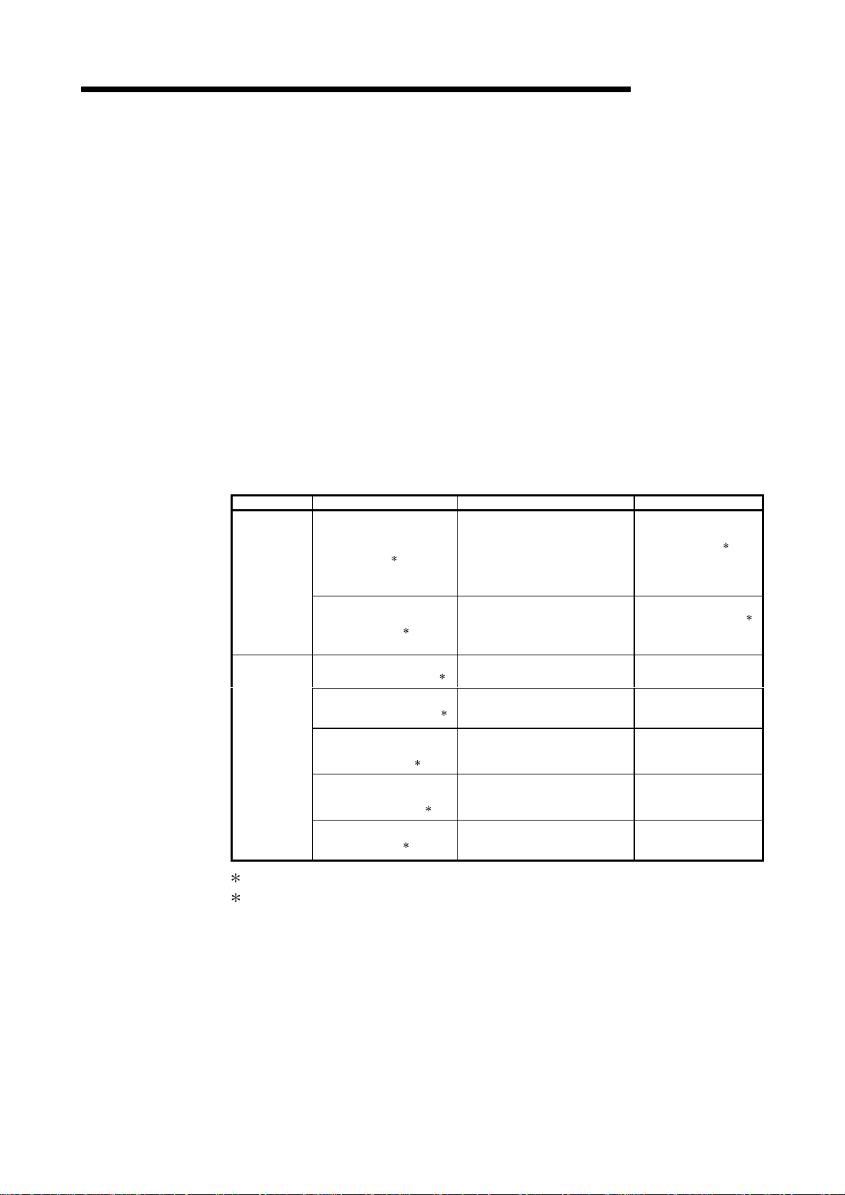
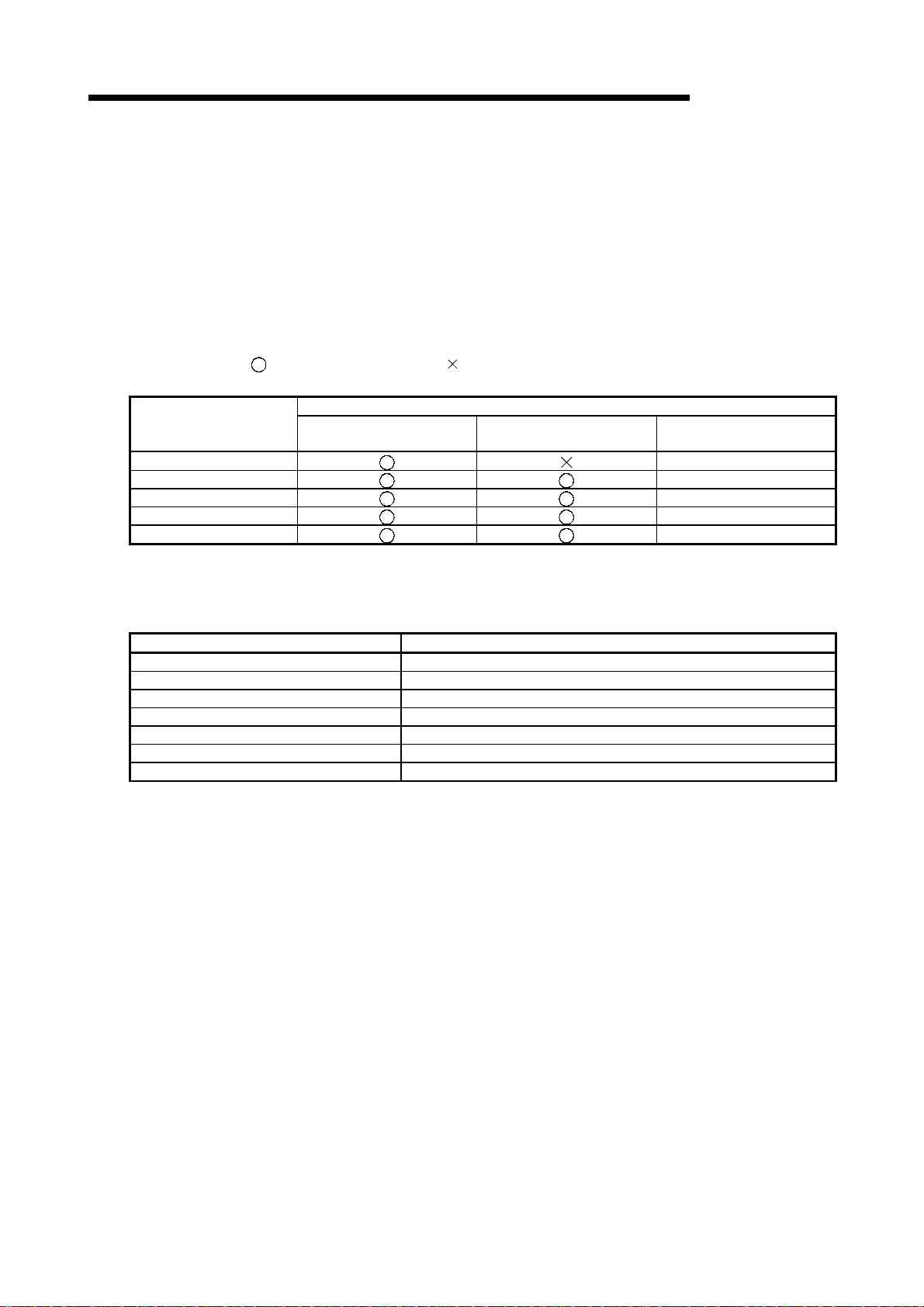
2.3.1 Caution points when using PC card/Fl ash PC card
The EMC directiv e may not be ap pli c able whe n usin g a PC ca rd or fl a sh PC card,
depending on the GOT used.
The table below shows whether the EMC directive is applicable when using each type
of GOT.
: EMC directive ap pli c ab le : EMC directive not appl icable
: Connection impossible
When the PC card is used
Type
A985GOT-TBA-EU
A975GOT-TBA-EU
A970GOT-TBA-EU
A970GOT-SBA-EU
A960GOT-EBA-EU
Commercial PC card
(SRAM type)
Flash PC card
(A9GTMEM-*MF)
Commercial flash PC card
2.3.2 About Modules that the EMC directive do not apply to
The EMC directive is not applicable when using the modules below.
Item Type
Bus connection board A9GT-QBUSS, A9GT-QBUS2S
Bus connection module A9GT-BUSSU, A9GT-BUS2SU
Serial communication board A9GT-RS2T
Data link module A7GT-J71AP23, A7GT-J71AR23, A7GT-J71AT23B
Network module A7GT-J71LP23, A7GT-J71BR13
CC-Link communication module A8GT-J61BT15
External I/O module A9GT-70KBF
2 - 5 2 - 5
2 SYSTEM CONFIGURATION
MELSEC-GOT
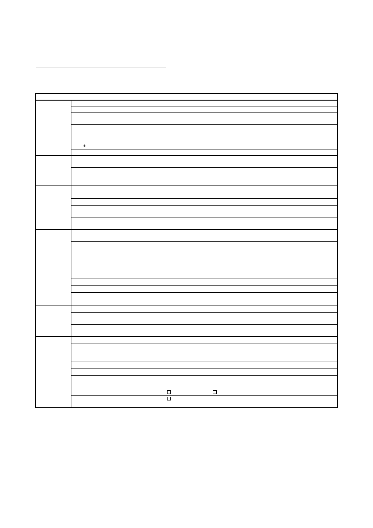
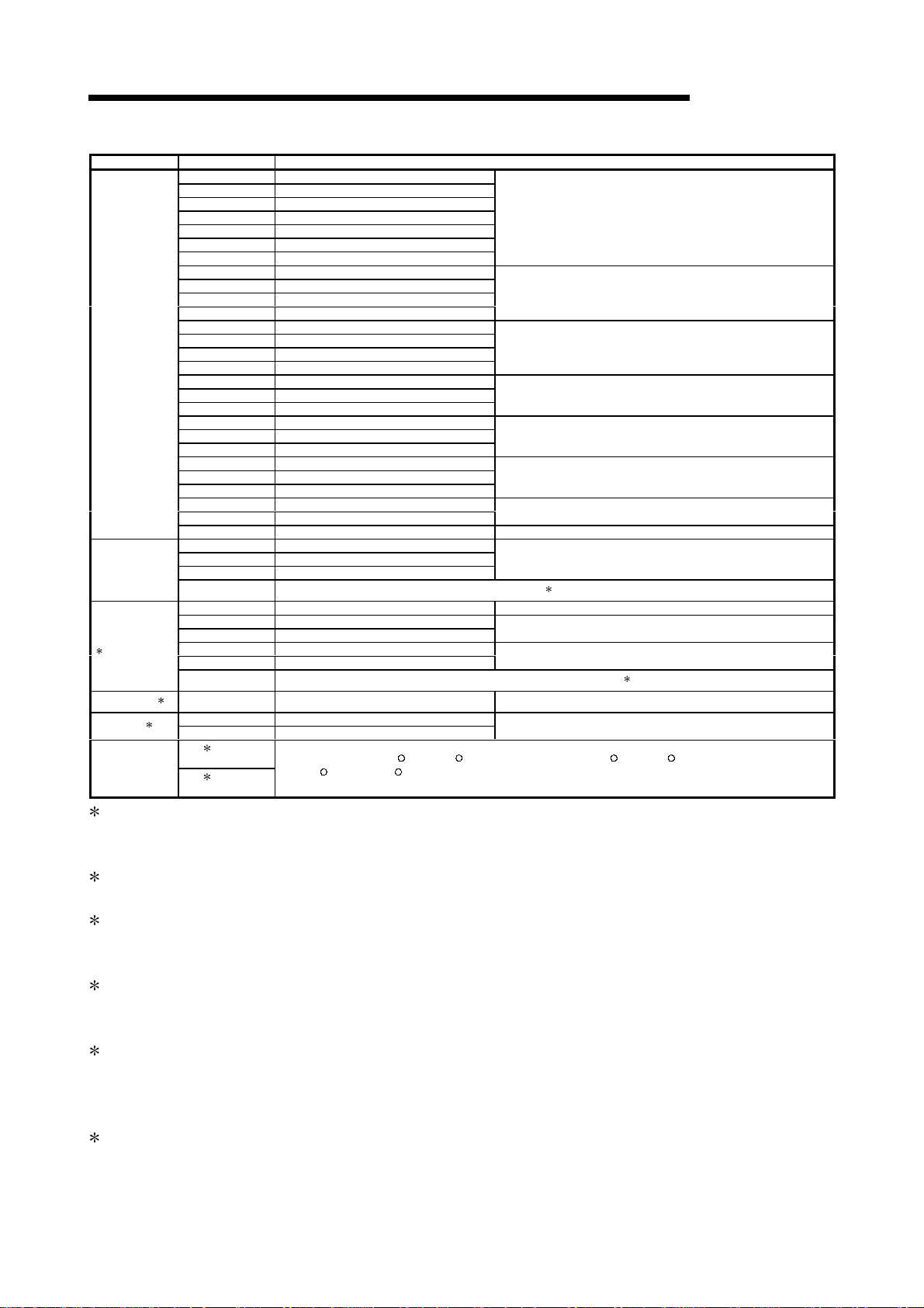
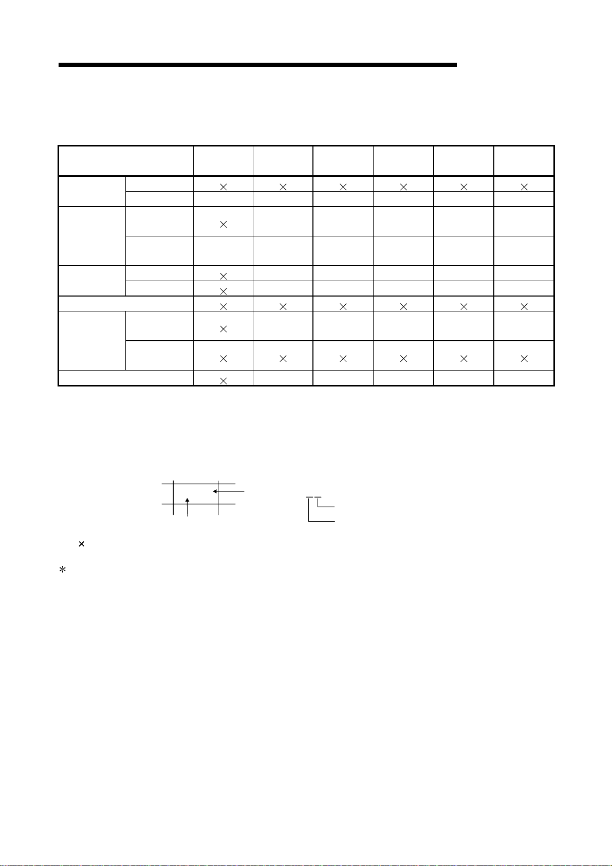
2.3.3 Connection Format
Connection conditions where the GOT applies to the EMC directive are shown below.
Connection format
Bus
Connection
CPU direct
connection
Computer link
connection
MELSECNET connection
CC-Link
connection
Ethernet connection Y(0203) Y(0203) M(0203) E(0203) Q(0203)
QCPU
QnA/ACPU A A A A A A
QCPU
(RS-232C)
QnA/ACPU
(RS-422)
RS-232C T(0105) T(0105) E(0105) A L(0105)
RS-422
Intelligent
device
Remote device
station
A985GOT-
TBA-EU
AAAAAA
A975GOT-
TBA-EU
T(0105) T(0105) E(0105) A L(0105)
AAAAA
T(0105) T(0105) E(0105) A L(0105)
A970GOT-
TBA-EU
A970GOT-
SBA-EU
A970GOT-
LBA-EU
A960GOT-
EBA-EU
<How to read the table>
The table indicates the GOT-compatible hardware version for each connection pattern and the
compatibility date. (The compatibility date of the GOT compatible with hardware version A is not
indicated.)
Please use the GOT whose hardware version is later than that described.
E(0105)
Hardware version
Compatibility
date
(0105)
Month
Year (Last 2 digits of A.D. year)
indicates the product is not compliant with the EMC Directive.
1 F or details about each connecti on condition, refer to the GOT-A900 Series Us er’s Manual (GT W orks
Version5/GT Designer Version5 compatible Connection System Manual).
2 - 6 2 - 6
2 SYSTEM CONFIGURATION
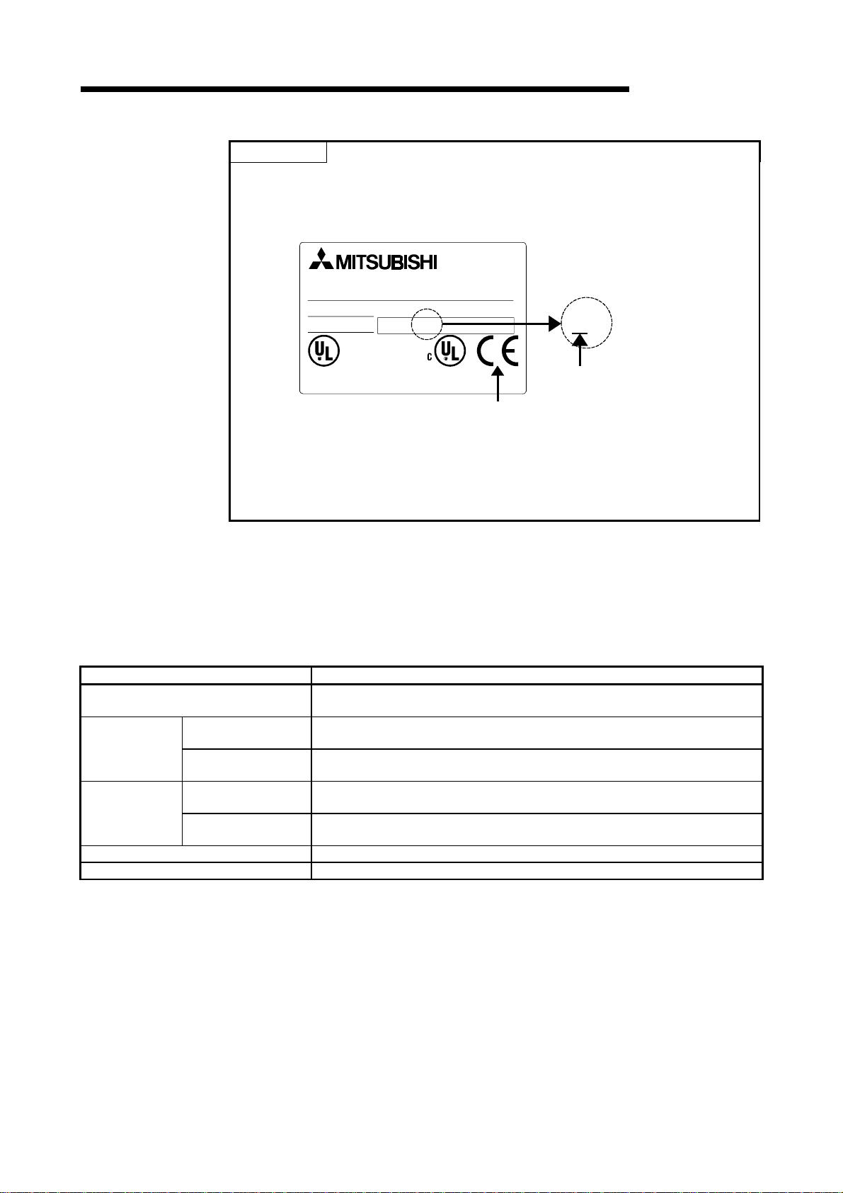
POINT
• About the hardware version
Confirm the hardware version with the products rating plate.
(Products that the EMC directive applies to are marked with the CE mark logo.)
MODEL
DATE
MITSU B IS HI E LE C TR IC CO R P OR A TIO N
MADE IN JAPAN
• About the connection destination device
If connecting to a PLC not from this company (MELSEC-Q series, MELSEC-QnA
series, MELSEC-A series), refer to the manual of the connected device (PLC,
microcomputer) for information about the applicability of the EMC directive.
GRAP HIC O P ER AT IO N TER M IN AL
A960GOT-EBA-EU
IN 100-240VAC 50/60Hz POWER M AX 115VA
0105LR
LISTED 80M1
IND. CONT. EQ.
BD992C082H01
CE mark logo
MELSEC-GOT
L R
Hardware version
2.3.4 When the communication module/board is used
If the EMC directive is applicable, use the communication module/board shown below.
(Available May, 2001).
If a communication module/board other than those shown below is used, it will not
apply to the EMC directive.
Connection format Communication module/board
Bus connection
RS-232C
CPU direct
connection
Computer link
connection
CC-Link connection A8GT-J61BT13 (Hardware version E or later)
Ethernet connection A9GT-J71E71-T (Hardware version C or later)
communication
RS-422
communication
RS-232C
communication
RS-422
communication
A9GT-BUSS (Hardware version C or later)
A9GT-BUS2S (Hardware version C or later)
A9GT-RS2 (Hardware version B or later)
A9GT-RS4 (Hardware version B or later)
A9GT-RS2 (Hardware version B or later)
A9GT-RS4 (Hardware version B or later)
2 - 7 2 - 7
 Loading...