

Mitsubishi A953GOT-SBD-M3-H, A953GOT-LBD-M3-H Hardware Manual

HARDWARE MANUAL
A953 HANDY GOT
TARGET MODELS (FOR RS-232C CONNECTION)
A953GOT-LBD-M3-H
A953GOT-SBD-M3-H

Foreword
• This manual contains text, diagrams and explanations which will guide the reader in the
correct installation and operation of the GOT-A900. It should be read and understood before
attempting to install or use the unit.
• Further information can be found in the GOT-900 Series Operating Manual (Introductory
Manual), GOT-A900 Series Operating Manual, GOT-A900 Series User’s Manual
• If in doubt at any stage of the installation of GOT-A900 always consult a professional
electrical engineer who is qualified and trained to the local and national standards which
apply to the installation site.
• If in doubt about the operation or use of GOT-A900 please consult the nearest Mitsubishi
Electric distributor.
• This manual is subject to change without notice.
A953 HANDY GOT

i
A953 HANDY GOT
HARDWARE MANUAL
Manual number : JY992D99801
Manual revision : C
Date : September 2008
A953 HANDY GOT

A953 HANDY GOT
ii

FAX BACK
Mitsubishi has a world wide reputation for its efforts in continually developing and pushing back
the frontiers of industrial automation. What is sometimes overlooked by the user is the care
and attention to detail that is taken with the documentation. However, to continue this process
of improvement, the comments of the Mitsubishi users are always welcomed. This page has
been designed for you, the reader, to fill in your comments and fax them back to us. We look
forward to hearing from you.
Fax numbers: Your name: ...................................................
Mitsubishi Electric.... .....................................................................
America (01) 847-478-2253 Your company: .............................................
Australia (02) 638-7072 .....................................................................
Germany (0 21 02) 4 86-1 12 Your location:................................................
Spain (34) 93-589-1579 .....................................................................
United Kingdom (01707) 278-695
Please tick the box of your choice
What condition did the manual arrive in?
Good
Minor damage
Unusable
Will you be using a folder to store the manual?
Ye s
No
What do you think to the manual presentation?
Tidy
Unfriendly
Are the explanations understandable?
Ye s
Not too bad
Unusable
Which explanation was most difficult to understand: ..................................................................
....................................................................................................................................................
Are there any diagrams which are not clear?
Ye s
No
If so,which: ..................................................................................................................................
What do you think to the manual layout?
Good
Not too bad
Unhelpful
If there one thing you would like to see improved, what is it?.....................................................
....................................................................................................................................................
....................................................................................................................................................
Could you find the information you required easily using the index and/or the contents, if
possible please identify your experience: ...................................................................................
....................................................................................................................................................
....................................................................................................................................................
....................................................................................................................................................
....................................................................................................................................................
Do you have any comments in general about the Mitsubishi manuals? .....................................
....................................................................................................................................................
....................................................................................................................................................
....................................................................................................................................................
....................................................................................................................................................
Thank you for taking the time to fill out this questionnaire. We hope you found both the product
and this manual easy to use.
A953 HANDY GOT
iii

A953 HANDY GOT
iv

A953 HANDY GOT
v
Guidelines for the Safety of the User and Protection of the A953 HANDY GOT
This manual provides information for the use of the A953 HANDY GOT. The manual has been
written to be used by trained and competent personnel. The definition of such a person or
persons is as follows;
a) Any engineer who is responsible for the planning, design and construction of automatic
equipment using the product associated with this manual should be of a competent
nature, trained and qualified to the local and national standards required to fulfill that
role. These engineers should be fully aware of all aspects of safety with regards to
automated equipment.
b) Any commissioning or service engineer must be of a competent nature, trained and
qualified to the local and national standards required to fulfill that job. These engineers
should also be trained in the use and maintenance of the completed product. This
includes being completely familiar with all associated documentation for the said product.
All maintenance should be carried out in accordance with established safety practices.
c) All operators of the completed equipment (see note) should be trained to use that
product in a safe manner in compliance to established safety practices. The operators
should also be familiar with documentation which is associated with the operation of the
completed equipment.
Note : The term ‘completed equipment’ refers to a third party constructed device which
contains or uses the product associated with this manual.
Notes on the Symbols Used in this Manual
At various times through out this manual certain symbols will be used to highlight points of
information which are intended to ensure the users personal safety and protect the integrity of
equipment. Whenever any of the following symbols are encountered, its associated note must
be read and understood. Each of the symbols used will now be listed with a brief description of
its meaning.
Hardware Warnings
1) Indicates that the identified danger WILL cause physical and property damage.
2) Indicates that the identified danger could POSSIBLY cause physical and property
damage.
3) Indicates a point of further interest or further explanation.
Software Warnings
4) Indicates special care must be taken when using this element of software.
5) Indicates a special point which the user of the associate software element should
be aware of.
6) Indicates a point of interest or further explanation.
A953 HANDY GOT
vi
• Under no circumstances will Mitsubishi Electric be liable responsible for any consequential
damage that may arise as a result of the installation or use of this equipment.
• All examples and diagrams shown in this manual are intended only as an aid to
understanding the text, not to guarantee operation. Mitsubishi Electric will accept no
responsibility for actual use of the product based on these illustrative examples.
• Please contact a Mitsubishi Electric distributor for more information concerning applications
in life critical situations or high reliability.
Abbreviations
The table below shows abbreviations, generic names and terms used in this manual.
Abbreviation/
generic name/term
Description
Handy GOT Generic name of A953GOT-LBD-M3-H and A953GOT-SBD-M3-H
A953 Handy GOT Generic name of A953GOT-LBD-M3-H and A953GOT-SBD-M3-H
A950GOT Generic name of A95*GOT
Built-in memory Abbreviation of memory (flush ROM) built in GOT
OS Abbreviation of GOT system software
External I/O unit Abbreviation of external I/O interface unit A8GT-50KBF
Printer interface unit Abbreviation of printer interface unit A9GT-50PRF
QCPU (Q mode)
Generic name of Q02CPU, Q02HCPU, Q06HCPU, Q12HCPU and
Q25HCPU CPU units
QCPU (A mode) Generic name of Q02CPU-A, Q02HCPU-A and Q06HCPU-A CPU units
QCPU Generic name of QCPU (Q mode) and QCPU (A mode) CPU units
QnACPU (large type)
Generic name of Q2ACPU, Q2ACPU-S1, Q3ACPU, Q4ACPU and
Q4ARCPU CPU units
QnACPU (small type)
Generic name of Q2ASCPU, Q2ASCPU-S1, Q2ASHCPU and
Q2ASHCPU-S1 CPU units
QnACPU
Generic name of QnACPU (large type) and QnACPU (small type) CPU units
AnUCPU
Generic name of A2UCPU, A2UCPU-S1, A3UCPU and A4UCPU CPU units
AnACPU Generic name of A2ACPU, A2ACPU-S1 and A3ACPU CPU units
AnNCPU
Generic name of A1NCPU A2NCPU, A2NCPU-S1 and A3NCPU CPU units
ACPU (large type) Generic name of AnUCPU, AnACPU and AnNCPU CPU units
A2US(H)CPU
Generic name of A2USCPU, A2USCPU-S1 and A2USHCPU-S1 CPU units
AnS(H)CPU Generic name of A1SCPU, A1SHCPU, A2SCPU and A2SHCPU CPU units
A1SJ(H)CPU Generic name of A1SJCPU-S3 and A1SJHCPU CPU units
ACPU (small type) Generic name of A2US(H)CPU, AnS(H)CPU and A1SJ(H)CPU CPU units
ACPU
Generic name of ACPU (large type), ACPU (small type) and A1FXCPU
CPU units
FX
1S
Series Generic name of FX1S Series CPU units
FX
1N
Series Generic name of FX1N Series CPU units
FX
2N
Series Generic name of FX2N Series CPU units
FX
2NC
Series Generic name of FX
2NC
Series CPU units
FXCPU Generic name of FX
1S
, FX1N, FX2N and FX
2NC
Series CPU units
Motion controller CPU
Generic name of A373UCPU, A373UCPU-S3, A273UCPU, A273UHCPU,
A273UHCPU-S3, A171SCPU-S3, A171SHCPU, A172SHCPU and
A173UHCPU
A953 HANDY GOT
vii
FA controller Generic name of LM610, LM7600 and LM8000
PLC by Omron
Generic name of C200HS, C200H, C200HX, C200HG, C200HE, CQM1,
C1000H, C2000H and CV1000
PLC by Yaskawa Electric
Generic name of GL60S, GL60H, GL70H, GL120, GL130, CP-9200SH,
CP-9300MS, MP-920 and MP-930
PLC by Allen-Bradley Generic name of SLC 5/03 and SLC 5/04
PLC by Siemens Generic name of SIMATIC S7-300 and SIMATIC S7-400
PLC by Sharp
Generic name of JW-21CU, JW-22CU, JW-31CUH, JW-32CUH, JW-33CUH,
JW-50CUH, JW-70CUH and JW-100CUH
PLC by Toshiba Generic name of T3 and T3H
PLC by another company
Generic name of PLC by Omron, PLC by Yaskawa Electric, PLC by Allen-
Bradley, PLC by Siemens, PLC by Sharp and PLC by Toshiba
GT Designer2
SWD5C-GOTR-PACKE
Screen creation software
Abbreviation of GOT Screen Designer (screen creation software for GOT900)
Data conversion software Abbreviation of GOT Converter (data conversion software for GOT900)
Debugging software Abbreviation of GOT Debugger (software for debugging function)
Object Set data to be made into dynamic images
Windows 95
Microsoft
®
Windows® 95 Operating system English version
Windows 98
Microsoft
®
Windows® 98 Operating system English version
Windows Me
Microsoft
®
Windows® Millennium Edition Operating system English
version
Windows NT 4.0
Microsoft
®
Windows NT® 4.0 Workstation Operating system English
version
Windows 2000
Microsoft
®
Windows® 2000 Operating system English version
Abbreviation/
generic name/term
Description
GT Works2
SW
D5C-GTWK2-E
Integrated screen development
software for GOT-900 Series
(SW
D5C-GTD2-E + GT Simulator
2 + GT Soft GOT2) (English version)
SWD5C-GTWS-E
Integrated screen development
software for GOT-900 Series
(SW
D5C-GTWK2-E + A9GTSOFT-
LKEY-P) (English version)
GT Designer2 SW
D5C-GTD2-E
Screen creation software for GOT900 Series (English version)
GT Works SWD5C-GTWORKS-E
Integrated screen development
software for GOT900 Series
(SW
D5C-GOTR-PACKE + GT
Simulator) (English version)
GT Designer
SW
D5C-GOTR-PACKE
Screen creation software for
GOT900 Series SWD5C-GOTRPACKE (English version)
SW
D5C-GOTR-
PACKEV
Software dedicated to version
upgrade from conventional version to
latest SW
D5C-GOTR-PACKE
(English version)

A953 HANDY GOT
viii
Associated Manuals
The configuration of manuals related to this Handy GOT is as shown below.
Explanation on specifications, installation, wiring and switches
A manual of the used Handy GOT is required.
• A953 HANDY GOT HARDWARE MANUAL
Describes the specifications, wiring, installation, etc. of the A953GOT-SBD-M3-H/A953GOTLBD-M3-H.
Manual No.: JY992D99801
Explanation on the display unit
Separate manual (Ask the sales agency from which you have purchased the Handy GOT.)
• A950GOT/A951GOT/A953GOT/A956GOT USERS MANUAL (DETAILED)
Describes the specifications of the A95*GOT, outline system configuration, components,
name of each part, unit attaching method, installation/wiring method, maintenance/
inspection method and error codes.
• GOT-A900 SERIES OPERATING MANUAL (EXTENTION FUNCTIONS/OPTIONAL
FUNCTIONS)
Describes the specifications of the utility function, system monitoring function, circuit
monitoring function, special function, unit monitoring function, network monitoring function
and list edition function which are provided in the A953 Handy GOT and available in the
A953GOT as well as the operation method of the dedicated monitor screen.
In the A953 Handy GOT, the PC card interface, external I/O interface and printer interface
are not available. Any bar code reader cannot be connected.
• GOT900 SERIES OPERATING MANUAL (INTRODUCTION)
Describes how to create monitor screens using the GT Designer, transfer the monitor data
to the GOT and display the screens for those who use the GOT for the first time.
Windows
Generic name of Windows95, Windows98, Windows Me, WindowsNT4.0
and Windows2000
Personal computer
Personal computer to Install the GT Designer or GT Designer 2 application
software
Abbreviation/
generic name/term
Description

A953 HANDY GOT
ix
Screen creation software
• GT Works2/GT Designer2 OPERATING MANUAL (STARTUP)
Describes how to install the GT Works2/GT Designer2 to a personal computer and how to
refer to the online manual.
• GT Designer2 (SWD5C-GTD2-E) REFERENCE MANUAL -separate manualDescribes how to install and start up the screen creation software (GT Designer2).
• GT Designer2 (SWD5C-GTD2-E) OPERATING MANUAL -separate manualDescribes how to operate the screen creation software (GT Designer2).
• GT Works Version 5/GT Designer Version 5 OPERATING MANUAL (STARTUP)
Describes how to install the GT Works Version 5/GT Designer Version 5 to a personal
computer and how to refer to the online manual.
(This manual is packed together with the GT Works Version 5/GT Designer Version 5.)
• GT Works Version 5/GT Designer Version 5 REFERENCE MANUAL -separate manualDescribes the system configuration of the GT Works Version 5/GT Designer Version 5, the
screen configuration of the GT Designer, various monitoring functions, procedures up to
displaying the monitor screen in the GOT and the help function use method.
• GT Simulator Version 5 OPERATING MANUAL -separate manualDescribes the system configuration, screen configuration and use method of the GT
Simulator.
Registration
Microsoft® Windows®, Windows® 95, Windows® 98, Windows® Millennium Edition, Windows
NT
®
4.0 Workstation and Windows® 2000 are either registered trademarks or trademarks of
Microsoft Corporation in United States and/or other countries.
The company name and the product name to be described in this manual are the registered
trademarks or trademarks of each company.

A953 HANDY GOT
x
Wiring procedure
The work procedures from starting up to making ready the Handy GOT using this manual are
explained below.
Outline
Reference page
1
1.2 Product configuration
1-3
Introduces the model name expression of the Handy GOT and accessories.
1.3 Introduction of cables and screen creation software (options) and
their applications
1-4
Introduces optional products (cables and connector conversion box) and explains their easy
applications.
1.4 Part identification
1-5
Explains the name and function of switches, lamps and connectors of the Handy GOT.
1.5 Applicable versions of OS and screen creation software
1-7
Explains versions of the system program (OS) and the screen creation software which are
compatible with the Handy GOT and to be prepared.
Outline of connection
Reference page
2
2.2.1 Outline of connection
2-5
Introduces configurations in accordance with applications.
2.2.2 Cable selection
2-7
Introduces combinations of cables between the Handy GOT and the PLC.
2.2.3 Pin arrangement and signal names of cables and connectors
2-8
Explains signal names of external cables and connector conversion box.
Installation
Reference page
3
2.1 Installation method
2-1
Introduces how to fix or hold by hand the Handy GOT.
2.2.4 Connection of external cable
2-9
Explains how to let an external cable go through the cable mounting slot of the Handy GOT and
fix it with screws.
2.3 Panel face processing
2-12
Introduces cables and connector box and explains the panel cut size for cases in which the
Handy GOT is attached to and detached from the panel face.

A953 HANDY GOT
xi
Wiring
Reference page
4
2.2.5 Wiring of power supply
2-11
Explains connection of an external cable and the DC power supply.
3.2 Wiring of operation switches
3-5
Explains how to wire four operation switches and control the LED indication.
3.3 Wiring of emergency stop switch
3-8
Explains the wiring of the emergency stop switch and the cautions.
3.4 Setting of grip switch
3-9
Explains the wiring of the grip switch and the cautions.

A953 HANDY GOT
xii
MEMO

A953 HANDY GOT
xiii
Contents
Table of Contents
Guideline of Safty.................................................................................v
Abbreviations...................................................................................................... vi
Associated Manuals...........................................................................................viii
Registration......................................................................................................... ix
Wiring procedure .................................................................................................x
1. Introduction............................................................................................1-1
1.1 Outline of product ................................................................................................1-1
1.2 Product configuration........................................................................................... 1-3
1.2.1 Handy GOT ............................................................................................................... 1-3
1.3 Introduction of cables and screen creation software (options) and their
applications.......................................................................................................... 1-4
1.3.1 Common options ....................................................................................................... 1-4
1.3.2 Options dedicated to A953 Handy GOT .................................................................... 1-4
1.4 Part identification .................................................................................................1-5
1.4.1 Front panel ................................................................................................................1-5
1.4.2 Rear panel.................................................................................................................1-6
1.5 Applicable versions of OS and screen creation software ....................................1-7
1.5.1 Applicable OS versions ............................................................................................. 1-7
1.5.2 Applicable screen creation software versions ........................................................... 1-7
2. Installation Wiring ..................................................................................2-1
2.1 Installation method .............................................................................................. 2-1
2.1.1 Holding ...................................................................................................................... 2-2
2.1.2 Hanging on wall ......................................................................................................... 2-3
2.1.3 Flat surface mounting................................................................................................ 2-3
2.2 Wiring .................................................................................................................. 2-4
2.2.1 Outline of connection................................................................................................. 2-5
2.2.2 Cable selection .......................................................................................................... 2-6
2.2.3 Pin arrangement and signal names of cables and connectors.................................. 2-7
2.2.4 Connection of external cable..................................................................................... 2-8
2.2.5 Wiring of power supply ............................................................................................ 2-10
2.3 Panel face processing .......................................................................................2-11
2.3.1 A953 Handy GOT .................................................................................................... 2-11
2.3.2 Appearance of relay cables ..................................................................................... 2-12
2.3.3 Panel cut size for relay cable .................................................................................. 2-13
A953 HANDY GOT

A953 HANDY GOT
xiv
Contents
3. Wiring and Handling of Switches...........................................................3-1
3.1 Outline of switches ..............................................................................................3-2
3.2 Wiring of operation switches................................................................................3-5
3.2.1 Inputs of operation switches ...................................................................................... 3-5
3.2.2 Lighting of operation indicator LEDs ......................................................................... 3-6
3.3 Wiring of emergency stop switch ......................................................................... 3-8
3.4 Setting of grip switch ........................................................................................... 3-9
3.4.1 Effectiveness/ineffectiveness of grip switch .............................................................. 3-9
3.4.2 Grip switch operation timing .................................................................................... 3-10
3.4.3 Communication with PLC ........................................................................................ 3-12
3.5 Creation of operation switch name sheet ..........................................................3-14
3.5.1 Creation of name sheet ........................................................................................... 3-14
3.5.2 Attachment of sheet ................................................................................................ 3-15
4. Specifications ........................................................................................4-1
4.1 General specifications .........................................................................................4-2
4.1.1 Outside dimensions ................................................................................................... 4-2
4.1.2 Power unit specifications ........................................................................................... 4-3
4.1.3 General specifications ............................................................................................... 4-3
4.2 PLC CPU which can be monitored ...................................................................... 4-5
4.2.1 In case of A953 Handy GOT ..................................................................................... 4-5
4.3 Devices names which can be monitored ............................................................. 4-6
5. Connection to Peripheral Equipment.....................................................5-1
5.1 Connection to peripheral equipment for Handy GOT .......................................... 5-1
5.2 Cable connection procedure................................................................................5-1
5.3 Connection diagram ............................................................................................5-2
6. CPU Direct Connection .........................................................................6-1
6.1 System configuration ........................................................................................... 6-1
6.1.1 Connection to QCPU ................................................................................................. 6-1
6.1.2 Connection to FXCPU ............................................................................................... 6-2
6.2 Connection cable.................................................................................................6-3
7. Computer Link Connection....................................................................7-1
7.1 System configuration ........................................................................................... 7-1
7.2 Initial setting......................................................................................................... 7-2
7.2.1 Setting in communication link unit and serial communication unit............................. 7-2
7.2.2 Setting in GOT........................................................................................................... 7-6
7.3 Transmission specifications.................................................................................7-6
7.4 Connection cable.................................................................................................7-7

A953 HANDY GOT
xv
Contents
8. Connection to PLC by Omron ...............................................................8-1
8.1 System configuration ........................................................................................... 8-1
8.1.1 System configuration when C200H/C200HS/C200Ha Series PLC is connected ...... 8-1
8.1.2 System configuration when CQM1 is connected....................................................... 8-2
8.1.3 System configuration when C1000H/C2000H is connected...................................... 8-2
8.1.4 System configuration when CV1000 is connected .................................................... 8-3
8.2 Initial setting......................................................................................................... 8-4
8.2.1 Setting of switches in upper link unit ......................................................................... 8-4
8.2.2 Setting in CV1000 ..................................................................................................... 8-6
8.2.3 Initialization of CQM1 ................................................................................................ 8-7
8.2.4 Communication board initialization program ............................................................. 8-7
8.3 Connection cable.................................................................................................8-8
9. Connection to PLC by Yaskawa Electric ...............................................9-1
9.1 System configuration ........................................................................................... 9-1
9.2 Initial setting......................................................................................................... 9-2
9.3 Connection cable.................................................................................................9-3
9.3.1 RS-232C cable .......................................................................................................... 9-3
10.Connection to PLC by Allen-Bradley ..................................................10-1
10.1 System configuration ......................................................................................... 10-1
10.2 Communication setting in PLC by Allen-Bradley ............................................... 10-1
10.3 Transmission specifications...............................................................................10-2
10.4 Connection cable...............................................................................................10-2
11.Connection to PLC by Sharp..............................................................11-1
11.1 System configuration ......................................................................................... 11-1
11.2 Initial setting....................................................................................................... 11-2
11.2.1 When GOT is directly connected to PLC CPU ........................................................ 11-2
11.2.2 When link unit is connected..................................................................................... 11-3
11.3 Transmission specifications...............................................................................11-4
11.4 Connection cable...............................................................................................11-5
12.Connection to Microcomputer ............................................................12-1
12.1 System configuration ......................................................................................... 12-1
12.2 Transmission specifications...............................................................................12-2
12.3 Connection cable...............................................................................................12-2
12.3.1 When DTR is used .................................................................................................. 12-2
12.3.2 When DTR is not used ............................................................................................ 12-4
12.4 Device data area ............................................................................................... 12-5
12.5 Communication command .................................................................................12-6
12.5.1 Command list .......................................................................................................... 12-6
12.5.2 Data transfer format ................................................................................................ 12-7
12.5.3 Caution on use ........................................................................................................ 12-8
12.5.4 Batch read command (RD)...................................................................................... 12-9
12.5.5 Batch write command (WD) .................................................................................. 12-10
12.5.6 Random read command (RR) ............................................................................... 12-11
12.5.7 Random write command (RW) .............................................................................. 12-12

A953 HANDY GOT
xvi
Contents
13.Connection to PLC by Siemens .........................................................13-1
13.1 System configuration ......................................................................................... 13-1
13.2 Initial setting....................................................................................................... 13-2
13.3 Connection cable...............................................................................................13-3
14.Diagnostics.........................................................................................14-1
14.1 When POWER LED does not light ....................................................................14-1
14.2 When an operation switch or emergency stop switch does not operate............14-2
14.3 When LC screen is dark ....................................................................................14-3
14.4 Error messages and error codes.......................................................................14-3
Appendix A: .............................................................................................. A-1
A-1: System Configuration Example in Microcomputer Connection............................A-1
A-1-1: System configuration .................................................................................................A-1
A-1-2: Communication setting in GOT and contents of setting on monitor screen ..............A-1
A-1-3: Sample program in host ............................................................................................A-3
A-1-4: Outline of system operations .....................................................................................A-3
A953 HANDY GOT
xvii
1
2
3
4
5
6
7
8
9
10
11
12
13
14
A
1 Introduction
2 Installation Wiring
3 Wiring and Handling of Switches
4 Specifications
5 Connection to Peripheral Equipment
6 CPU Direct Connection
7 Computer Link Connection
8 Connection to PLC by Omron
9 Connection to PLC by Yaskawa Electric
10 Connection to PLC by Allen-Bradley
11 Connection to PLC by Sharp
12 Connection to Microcomputer
13 Connection to PLC by Siemens
14 Diagnostics
A Appendix A
A953 HANDY GOT
A953 HANDY GOT
xviii
1 Introduction
2 Installation Wiring
3 Wiring and Handling of Switches
4 Specifications
5 Connection to Peripheral Equipment
6 CPU Direct Connection
7 Computer Link Connection
8 Connection to PLC by Omron
9 Connection to PLC by Yaskawa Electric
10 Connection to PLC by Allen-Bradley
11 Connection to PLC by Sharp
12 Connection to Microcomputer
13 Connection to PLC by Siemens
14 Diagnostics
A Appendix A
Introduction 1
1-1
1
2
3
4
5
6
7
8
9
10
11
12
13
14
A
1. Introduction
This section describes the product configuration and the system configuration of the A95
handy graphic operation terminal (abbreviated as "Handy GOT" in the text).
1.1 Outline of product
The Handy GOT is used as an operation terminal connected to a controller such as the
MELSEC FX/QnA/Q Series PLC and a PLC manufactured by another company.
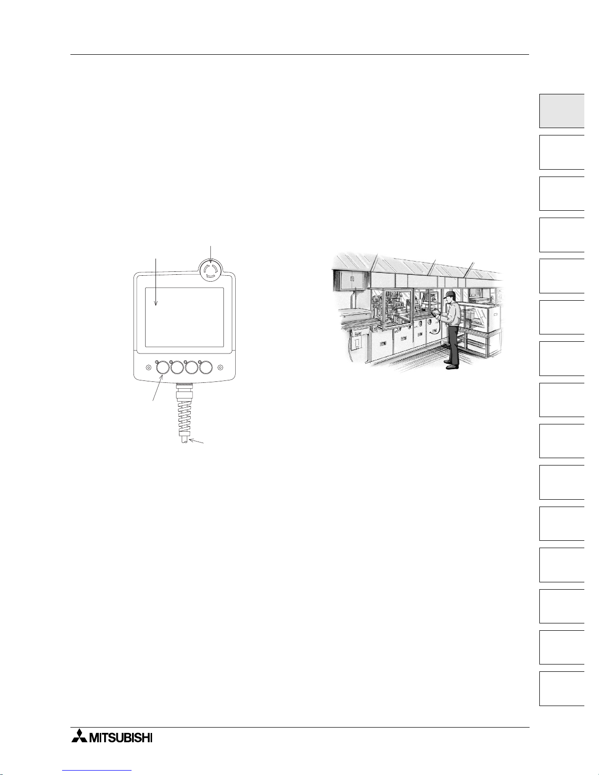
The Handy GOT is an all-in-one type graphic operation terminal equipped with a display unit
with touch switches and mechanical keys (operation switches) available to input commands to
the machine.
Operation switches:
They are mechanical keys directly connected to inputs of the PLC.
Because they give commands directly to inputs of the PLC, they can be used for inputs
requiring immediate responses to the machine such as inputs for operation and stop.
These switches are offered for the operator who gives operation commands to the machine.
• Start/stop
• Preparation for operation
• Setup change
• Error reset
• Mode selection between automatic and individual
* You can arbitrarily change the name of these operation switches using a transparent sheet
and a mount sheet offered as accessories.
P O W E R G R I P S W
E m e r g e n c y s t o p s w i t c h
D i s p l a y u n i t
O p e r a t i o n
s w i t c h e s
C o n n e c t i o n c a b l e
( o p t i o n )
Use example:
A953 HANDY GOT

A953 HANDY GOT Introduction 1
1-2
Display unit:
The display unit is an LCD with touch switches equivalent to that of the graphic operation
terminal A950GOT.
The operator can easily monitor the ON/OFF status of bit devices of the PLC, set such bit
devices to ON or OFF, monitor the set value and the present value of word devices of the PLC,
and change such values of word devices.
This display unit can be used to change the setup, change the set values, and perform
troubleshooting by the engineer, as well as give guidance to the operator.
• Selection of individual operation
• Independent operation
• One-cycle operation
• Monitoring
• Forcedly turning ON/OFF
• Change of set values
• Troubleshooting
(You can create screens displayed on the display unit using the screen creation software which
runs in a personal computer.)
Connection cable:
An optional connection cable is offered to connect the PLC.
A953 HANDY GOT Introduction 1
1-3
1
2
3
4
5
6
7
8
9
10
11
12
13
14
A
1.2 Product configuration
The model name of the Handy GOT is expressed as follows.
A95GOT-BD-M3-H
1) 2)
1) 3: RS-232C communication type
2) S: STN type eight-color liquid crystal
L: STN type black-and-white liquid crystal
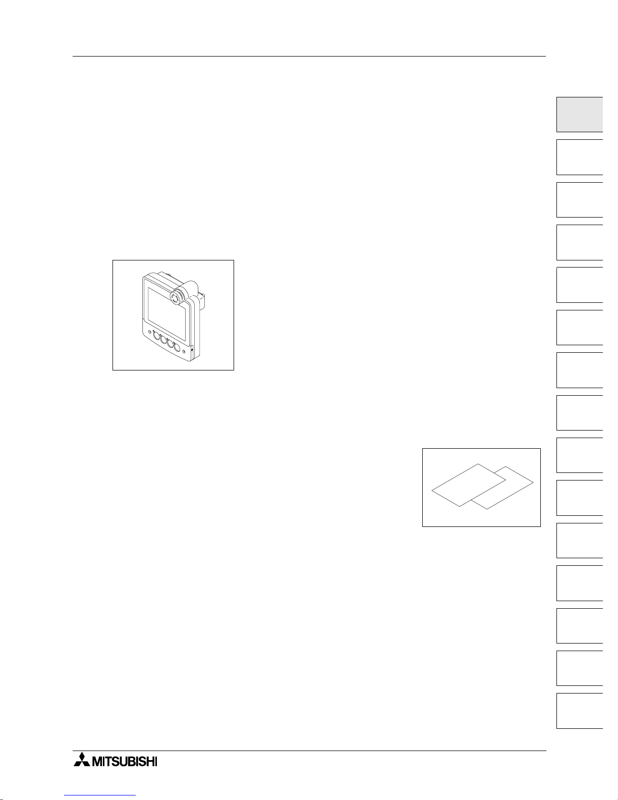
1.2.1 Handy GOT
The handy graphic operation terminal consists of the following components.
Handy GOT
Accessories: The following accessories are attached to the Handy GOT (in each model).
A transparent sheet 1) and a mount sheet 2) are offered as accessories so that the operation
switch names can be changed.
For the switch name changing procedure, refer to section 3.5.
1) Transparent sheet
2) Mount sheet
3) Manual (this manual)
Explains how to connect the PLC and the power supply.
P O W E R
G R IP S W
1 )
2 )
M o u n t
s h e e t
T r a n s p a r e n t
s h e e t
A953 HANDY GOT Introduction 1
1-4
1.3 Introduction of cables and screen creation software (options) and their
applications
Order the following options in accordance with the connected PLC configuration.
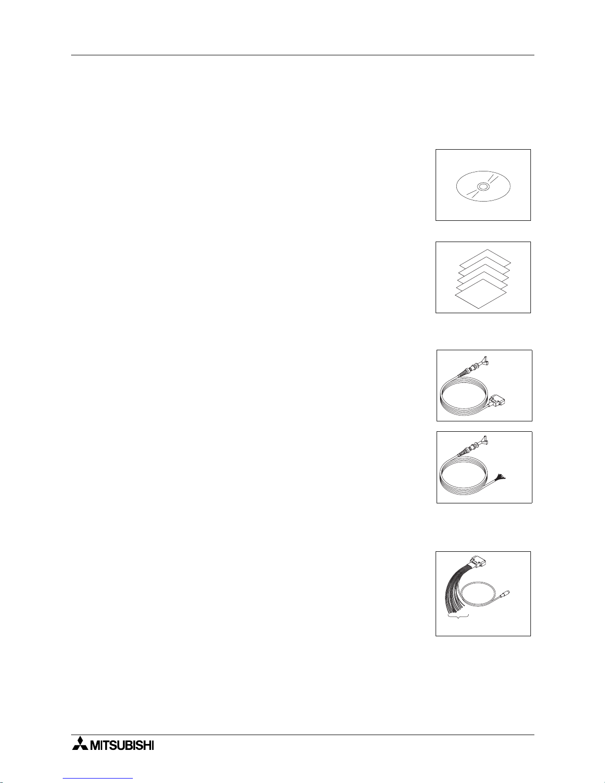
1.3.1 Common options
1) Screen creation software
For the details of versions applicable in the Handy GOT and the
software working environment, refer to 1.5.
- Screen creation system startup software SWD5C-GOTRPACKE (V)
"V" at the end of the model name indicates that this software is
for version upgrade.
- Screen creation system startup software SWD5C-GTD2-E
2) Protective sheets F9GT-40PSC (5 sheets in 1 set)
Each of these sheets protects the display unit against dirt when
adhered on the display unit.
1.3.2 Options dedicated to A953 Handy GOT
External cable
• External cable F9GT-HCAB-3M (with a 25-pin D-Sub connector on
one side) (3m
, 9' 10"
)
This cable connects the Handy GOT and an external equipment
(such as communication unit, power supply unit, operation switches
and emergency stop switch).
• External cable F9GT-HCAB1-3M (with untied wires on one side)
(3m, 9' 10")
This cable connects the Handy GOT and an external equipment
(such as communication unit, power supply unit, operation switches
and emergency stop switch).
Use this cable when connecting an external equipment to the PLC
directly or through a relay connector.
PLC connection cable
• Relay cable F9GT-HCAB5-150 (1.5m, 4' 11") for PLC connection
This cable is equipped with the 6-pin MINI DIN connector to directly
connect the Q Series PLC and untied wires to connect the power
supply, the operation switches and the emergency stop switch.
Use this cable together with the external cable F9GT-HCAB-3M
(with 25-pin D-Sub connector).
F o r u n t i e d
w i r e s
F o r 2 5 - p i n
D - S u b
c o n n e c t o r
T o P L C
F o r p o w e r s u p p l y a n d
o p e r a t i o n s w i t c h e s
A953 HANDY GOT Introduction 1
1-5
1
2
3
4
5
6
7
8
9
10
11
12
13
14
A
1.4 Part identification
This section roughly explains the name and function of each part of the Handy GOT.
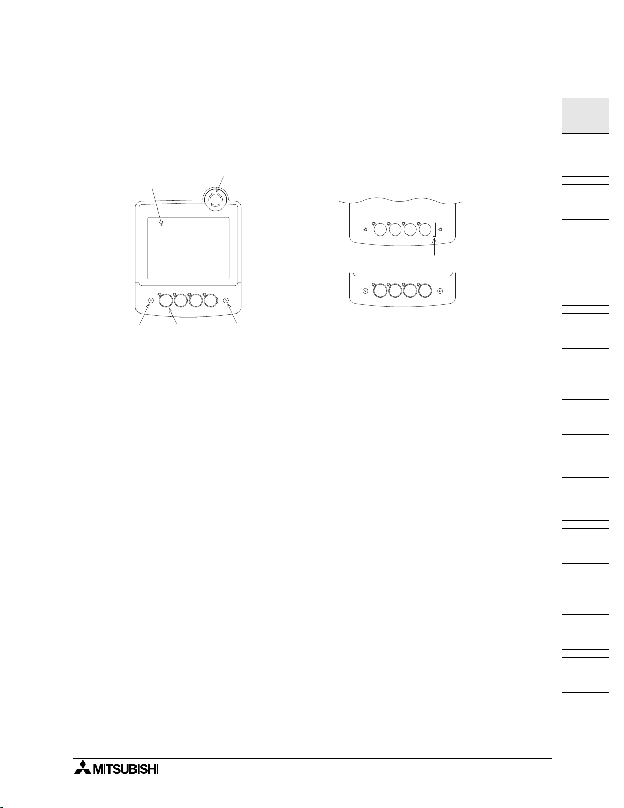
1.4.1 Front panel
The name and function of each part of the front panel of the Handy GOT are described below.
1) POWER LED
Lit while 24V DC power is supplied to the Handy GOT.
2) LC display unit with touch switches
Offers 8 colors in the A953GOT-SBD-M3-H or 2 colors (black and white) in the A953GOTLBD-M3-H.
This display unit offers the functions equivalent to those offered by the display unit of the
graphic operation terminal A950GOT.
Display size: 320 × 240 dots
Effective display size: 115(4.53") W × 86(3.39") H mm
3) Operation switches (Refer to section 3.2.)
Directly connected to inputs of the PLC.
Each of these four switches is equipped with a green LED which indicates the pressing
status. The information on the green LED lighting command is transferred between the PLC
through serial communication.
The operator can arbitrarily set the display control using a PLC program.
The operator can arbitrarily change the name of these four switches using sheets offered as
accessories. (Refer to section 3.5.)
4) Emergency stop switch (Refer to section 3.3.)
Is a switch with independent contact of 24V DC specification.
5) Grip switch LED (Refer to section 3.4.)
Lit while the grip switch provided on the side is pressed and held.
6) Operation switch name sheet insertion slot (Refer to section 3.5.)
Can be seen when the operation switch cover is removed from the lower portion of the
Handy GOT.
P O W E R G R I P S W
1 )
2 )
3 )
4 )
5 )
P O W E R G R I P S W
W h e n t h e o p e r a t i o n s w i t c h c o v e r i s r e m o v e d
O p e r a t i o n s w i t c h c o v e r
6 )
A953 HANDY GOT Introduction 1
1-6
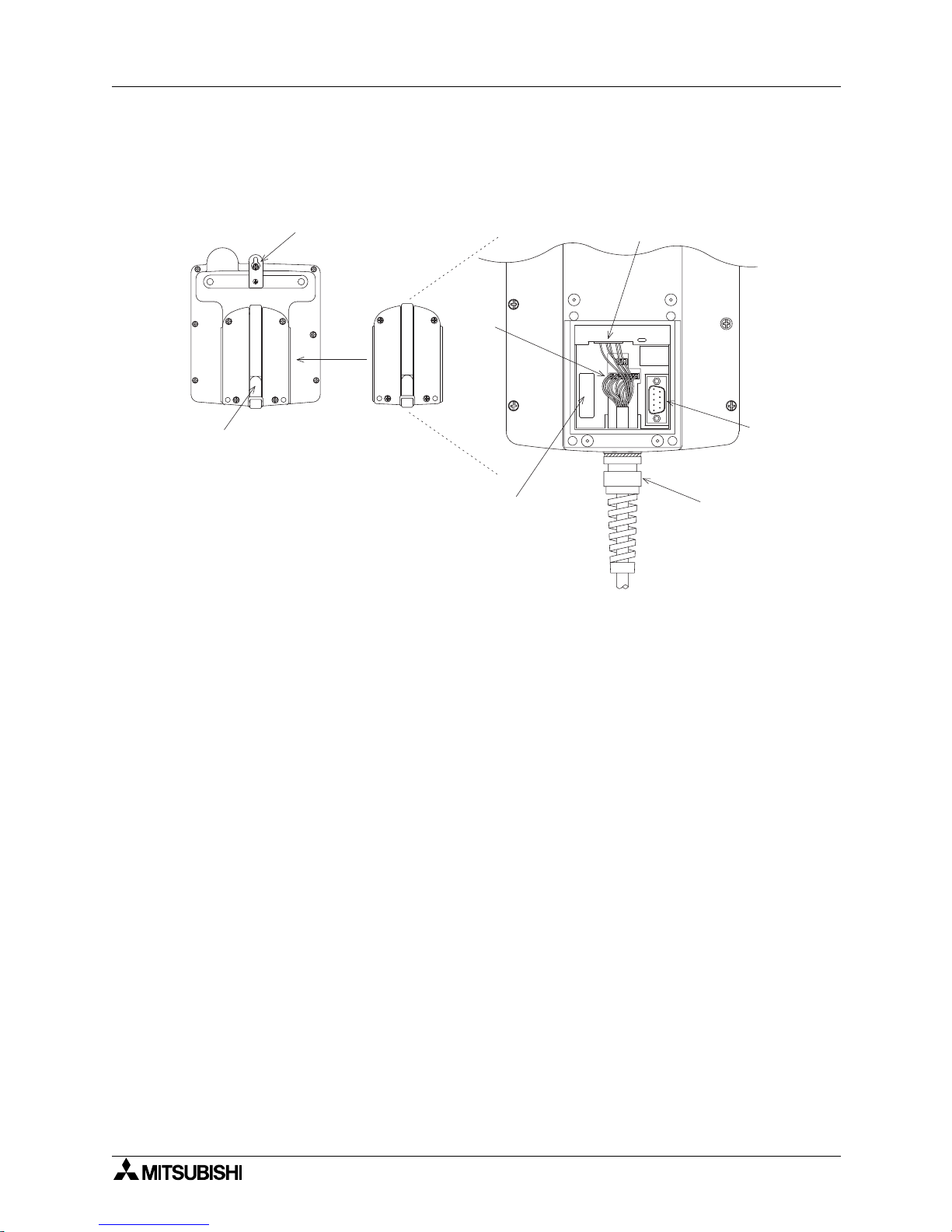
1.4.2 Rear panel
The name and function of each part of the rear panel of the Handy GOT are described below.
When the rear cover is removed, diversified connectors can be seen.
1) Hand strap
Is a strap whose length is adjustable to allow the operator to comfortably hold the Handy
GOT.
2) Metal hook for mounting on the wall
Is offered to mount the Handy GOT on the wall for operation and accommodation.
3) External cable (Refer to section 2.2.)
Is offered as an option to connect a PLC (for RS-232C communication), power supply and
operation switches, and connected to the connectors 3)' in two positions.
4) Port for personal computer (9-pin D-Sub, male) (for RS-232C communication) (Refer to
chapter 5.)
Is offered to transfer the screen data created using the screen creation software.
1 )
2 )
3 ) '
N o t u s e d
3 )
4 )
3 ) '
W h e n t h e r e a r c o v e r i s r e m o v e d ( e n l a r g e d v i e w )
A953 HANDY GOT Introduction 1
1-7
1
2
3
4
5
6
7
8
9
10
11
12
13
14
A
1.5 Applicable versions of OS and screen creation software
When using the Handy GOT, make sure to prepare the OS and the screen creation software of
the version shown below.
1.5.1 Applicable OS versions
Because the BIOS is already assembled in the Handy GOT at the time of shipment, you do not
have to transfer it using the screen creation software.
Transfer the OS to the Handy GOT in accordance with the operating procedure described in
the manual of the screen creation software shown below.
(The PLC card interface and the printer interface are not available.)
1.5.2 Applicable screen creation software versions
"V" at the end of the model name indicates that the software is for version upgrade.
For connection of the screen creation software (personal computer) and the Handy
GOT, refer to chapter 5.
Handy GOT Applicable BIOS OS version
A95GOT-SBD-M3-H
A95GOT-LBD-M3-H
version M version 7.1.0 or later
GT Designer2 SWD5C-GTD2-E Screen creation software for GOT-900 Series
GT Works2
SWD5C-GTWK2-E
Integrated screen development software for GOT-900
Series
(SWD5C-GTD2-E + GT Simulator2 + GT SoftGOT2)
SWD5C-GTWS-E
Integrated screen development software for GOT-900
Series
(SWD5C-GTWK2-E + A9GTSOFT-LKEY-P)
GT Designer SWD5C-GOTR-PACKE(V)
Screen creation software for GOT-900 Series
: 4 or larger (version F or later)
Product shipped in May, 2000 or later
GT Works SWD5C-GTWORKS(-E)
Integrated screen development software for GOT-900
Series
"SWD5C-GOTR-PACKE + GT Simulator" is packed
together.

A953 HANDY GOT Introduction 1
1-8
MEMO
Installation Wiring 2
2-1
1
2
3
4
5
6
7
8
9
10
11
12
13
14
A
2. Installation Wiring
This section describes installation of the Handy GOT and wiring of the power supply and the
operation switches.
Thoroughly understand the specifications before performing installation and wiring.
2.1 Installation method
Cautions on installation
• Use the Handy GOT in the general specifications environment described in this manual.
Do not use the Handy GOT in a place with dusts, soot, conductive dusts, corrosive gas or
flammable gas, place exposed to high temperature, dew condensation, direct sunlight,
wind and rain, or place exposed to vibration or impact.
If the Handy GOT is used in such a place, electrical shock, fire, malfunction, product
damage or deterioration may caused.
• Never drop cutting chips and electric wire chips into the ventilation window of the Handy
GOT when you drill screw holes or perform wiring.
Otherwise, fire, failure or malfunction may be caused.
• Connect connection cables securely to the specified connectors while the power is
turned OFF.
Imperfect connection may cause malfunction or failure.
• When connecting cables, pay attention to the contents described in this section.
Especially, attach the rear cover so that PCBs inside the Handy GOT are not interfered
with connection cables.
Cautions on wiring
• Make sure to attach the rear cover to the Handy GOT before turning on the power and
starting operation after the installation or wiring work.
Otherwise, electrical shock may be caused.
• Make sure to shut down all phases of the power outside the Handy GOT before starting
the installation or wiring work.
Otherwise, electrical shock and damage of Handy GOT may be caused.
A953 HANDY GOT
A953 HANDY GOT Installation Wiring 2
2-2
Cautions on wiring
• The Handy GOT has the DC power specifications. Connect the DC power cable to the
dedicated terminals described in this manual.
If the AC power is supplied to the power supply, operation switches or emergency stop
switches, the Handy GOT may be burnt.
• Correctly connect the 24V DC power cable (terminals) of the Handy GOT to [+][-] of the
DC power supply unit as described in this manual.
If reversing the terminals will seriously damage the Handy GOT.
• Perform the groundings to the drain wire (FG) of the Handy GOT. Never perform common
grounding with the strong power system.
• When processing a cable or executing the wiring work, pay attention so that cutting chips
and wire chips do not enter the inside of the Handy GOT.
Such chips may cause fire, failure or malfunction.
Note
Even if the power is interrupted for less than 1 ms, the Handy GOT continues operation. If the
power is interrupted for a long time or the voltage is dropped, the Handy GOT stops operation.
When the power is restored, however, the GOT automatically restarts operation.
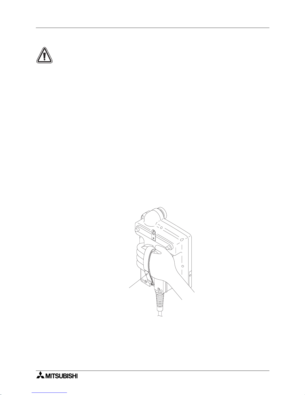
2.1.1 Holding
When holding the Handy GOT for operation, place your hand through the hand strap provided on its rear
face. You can adjust the length of the hand strap.
H a n d s t r a p
 Loading...