

Page 1

A8GT-J61BT15 Type CC-Link Communication Module
User,s Manual
Mitsubishi Graphic Operation Terminal
Page 2
SAFETY PRECAUTIONS
•
(Always read these instructions before using this equipment.)
Before using this product, please read this manual and the relevant manuals introduced in this manual
carefully and pay full attention to safety to handle the product correctly.
The instructions given in this manual are concerned with this product. For the safety instructions of the
programmable controller system, please read the CPU module user's manual.
In this manual, the safety instructions are ranked as "DANGER" and "CAUTION".
•
DANGER
!
CAUTION
!
Note that the !CAUTION level may lead to a serious consequence according to t he circumstances.
Always follow the instructions of both levels because they are important to personal safety.
Please save this manual to make it accessible when required and always forw ard it to the end user.
Indicates that incorrect handling may cause hazardous conditions,
resulting in death or severe injury.
Indicates that incorrect handling may cause hazardous conditions,
resulting in medium or slight personal injury or physical damage.
[Design Precautions]
!
DANGER
Some faults of this module may keep the outputs on or off. An external monitoring circuit should
•
therefore be provided to check for output signals which may lead to a serious accident.
Not doing so can cause an accident due to mis-output or misoperation.
If a communication error (including cable disconnection) occurs during monitoring with the GOT,
•
communication between the GOT and master station is interrupted, disabling operation.
When using the GOT to configure a sys tem, as sume that a GOT c ommunicat ion error will occu r
and configure a system in which switches used to perform significant operation for the system
are provided on any device other than the GOT.
Not doing so can cause an accident due to mis-output or misoperation.
Read Chapter 5 “Data Link Processing Time” in the Master Module User’s Manual carefully
•
regarding the status of each station when the PLC CPU operation is stopped or the dat a link
becomes a communication error.
Also, configure an interlocking circuit in the sequence program using the communication st atus
information (SB and SD) so that the overall system is alw ays maintaine d.
An accident may occur by false output or malfunction.
Received data form master or local data link faulty station.
•
1) Remote input (RX) and remote output
This varies depending on the setting of the module’s condition setting switch and input dat a
(SW4) of the data link faulty station.
OFF : CLEAR (all off)
ON : Keeps the data right before the error occurrence.
2) Remote registers (RWw and RWr)
The data right before the error is kept regardless of the SW4 setting.
A - 1 A - 1
Page 3
[Design Precautions]
!
CAUTION
Do not bundle control lines or communication cables with the main circuit, power or other lines
•
or lay them near these lines.
As a guideline, separate the cables at least 100mm(3.94inch).
Not doing so can cause misoperation due to noise.
[Mounting Precautions]
!
DANGER
Before mounting or dismounting the module to or from the GOT, always switch off GOT power
•
externally in all phases.
Not doing so can cause a module failure or misoperation.
!
CAUTION
Use this module in an environment that conforms to the general specifications given in the G OT
•
user's manual.
Not doing so can cause an electric shock, fire, misoperation, or product damage or deterioration.
When mounting the module to the GOT, tighten the module fixing screws within the specified
•
torque range.
Undertightening can cause a drop, short circuit or misoperation.
Overtightening can cause a drop, short circuit or misoperation due to damaged screws or module.
[Wiring Precautions]
!
DANGER
Before starting wiring work, always switch GOT power off externally in all phases.
•
Not doing so can cause an electric shock, product damage or misoperation.
!
CAUTION
When switching power on or starting operation after mounting, wiring or other work, always fit
•
the terminal cover supplied to the product.
Not doing so can cause an electric shock, short circuit or failure.
Always ground the FG terminal of the GOT power supply and the FG1 termial of this module to
•
the protective ground conducter.
Be sure to ground the GOT and this module separately.
Not doing so may cause an electric shock or misoperation.
A - 2 A - 2
Page 4
[Wiring Precautions]
!
CAUTION
Before wiring the module, confirm the rated voltage and terminal arrangement of the product.
•
A fire or failure can occur if the power supply connected is different from the rating or wiring is
incorrect.
Tighten the terminal screws within the specified torque range.
•
Undertightening can cause a short circuit or misoperation.
Overtightening can cause a short circuit or misoperation due to damaged screws or module.
Ensure that foreign matters such as chips and wire off-cuts do not enter the module.
•
They can cause a fire, failure or misoperation.
Always secure the communication cables connected to the module, e.g. run them in conduits or
•
clamp them.
Not doing so can damage the module or cables due to dangling, moved or accidentally pulle d
cables or can cause misoperation due to cable contact fault.
Do not hold the cable part when unplugging the communication cable connected to t he module.
•
Disconnect the cable after loosening the screw in the part connected t o the module.
If you pull the cable connected to the module, the module or cable can be damaged or
misoperation can occur due to cable connection fault.
[Startup/Maintenance Precautions]
!
DANGER
Do not touch the terminals while power is on.
•
Doing so can cause an electric shock or misoperation.
Before starting cleaning or terminal screw retightening, always switch power off externally in all
•
phases.
Not doing so can cause a module failure or misoperation.
Undertightening can cause a drop, short circuit or misoperation.
Overtightening can cause a drop, short circuit or misoperation due to damaged screws or module.
!
CAUTION
Do not disassemble or modify the module.
•
Doing so can cause a failure, misoperation, injury or fire.
Do not touch the conductive areas and electronic parts of the module.
•
Doing so can cause the module to misoperate or fail.
Do not change any switch setting while power is on.
•
Doing so can cause a failure or misoperation.
The module is made of resin. Do not drop it or subject it to strong impact.
•
Doing so can damage the module.
Always make sure to touch the grounded metal to discharge the electricity charged in the body,
•
etc., before touching the module.
Failure to do so may cause a failure or malfunctions of the module.
A - 3 A - 3
Page 5

[Disposal Precautions]
!
CAUTION
When disposing of the product, treat it as industrial waste.
•
A - 4 A - 4
Page 6

REVISIONS
* The manual number is given on the bottom left of the back cover.
Print Date * Manual Number Revision
Aug., 1997 IB (NA) 66788-A First edition
Aug., 2001 IB (NA) 66788-B • The manual layout was rearranged.
Models added
GOT-A900 Series
Jun., 2004 IB (NA) 66788-C
Partial corrections
SAFETY PRECAUTIONS, About Manuals
MODEL CODE change
Changed from 13JL29 to 1DM074
Japanese Manual Version IB-68909-D
This manual confers no industrial property rights or any rights of any other kind, nor does it confer any patent
licenses. Mitsubishi Electric Corporation cannot be held responsible for any problems involving industrial property
rights which may occur as a result of using the contents noted in this manual.
1997 MITSUBISHI ELECTRIC CORPORATION
A - 5 A - 5
Page 7

INTRODUCTION
Thank you for purchasing the Mitsubishi Graphic Operation Terminal.
Before using the equipment, please read this manual carefully to develop full familiarity with the functions
and performance of the graphic operation terminal you have purchased, so as to ensure correct use.
Please forward a copy of this manual to the end user.
CONTENTS
Safety Precautions..........................................................................................................................................A- 1
Revisions.........................................................................................................................................................A- 2
About manuals ................................................................................................................................................A- 8
Conformation to the EMC Directive................................................................................................................A- 9
Abbreviations and generic theism in this manual ..........................................................................................A-10
1. OVERVIEW 1- 1 to 1- 2
2. SYSTEM CONFIGURATION 2- 1 to 2- 3
2.1 Overall Configuration..................................................................................................... ..........................2- 1
2.2 Instructions for System Configuration.....................................................................................................2- 2
3. SPECI FICATIONS 3- 1 to 3- 2
3.1 General Specifications.............................................................................................................................3- 1
3.2 Performance Specifications.....................................................................................................................3- 1
4. MONITORING SPECIFICATION 4- 1 to 4-30
4.1 Monitoring Overview................................................................................................................................4- 1
4.2 Monitorable Access Range and Device Specifying Method.................................................................. 4- 6
4.2.1 Monitorable access range................................................................................................................4- 6
4.2.2 How to specify devices when creating the monitor screen.............................................................4- 6
4.3 I/O Signals to the Master Module............................................................................................................4- 7
4.3.1 List of I/O signals..............................................................................................................................4- 7
4.3.2 Details of the I/O signals ..................................................................................................................4- 9
4.4 Remote Register Allocation..................................................................................................................... 4-1 1
4.5 Command List for the Dedicated Command Monitor Method................................................................4-12
4.6 Details of Each Command.......................................................................................................................4-13
4.6.1 Initial setting command ....................................................................................................................4-14
4.6.2 Continuous read command..............................................................................................................4-16
4.6.3 Random read command ..................................................................................................................4-18
4.6.4 Continuous write command.............................................................................................................4-20
4.6.5 Random write command..................................................................................................................4-22
4.6.6 Monitor register command...............................................................................................................4-24
4.6.7 Monitor request command...............................................................................................................4-24
4.6.8 Always write register command.......................................................................................................4-27
4.6.9 Always write request command....................................................................................................... 4-27
A - 6 A - 6
Page 8

5. PRE-OPERATION SETTINGS AND PROCEDURE 5- 1 to 5- 7
5.1 Pre-Operation Procedure ........................................................................................................................5- 1
5.2 Names of the Parts and Their Settings...................................................................................................5- 3
5.3 Handling Instructions ...............................................................................................................................5- 5
5.4 Mounting Procedures ..............................................................................................................................5- 6
5.5 Wiring Method..........................................................................................................................................5- 7
6. PROGRAMMING 6- 1 to 6- 8
6.1 Sequence Program Example When Monitoring Using the Normal Monitor Method.............................6- 1
6.1.1 System configuration of the program example ...............................................................................6- 1
6.1.2 Relationship among the PLC CPU, master station buffer memory,
and remote device stations .............................................................................................................6- 1
6.1.3 Examples of created monitor screen data.......................................................................................6- 2
6.2 Sequence Program Example When Monitoring Using Dedicated Command Monitor Method............6- 5
6.2.1 System configuration of the program example ...............................................................................6- 5
6.2.2 Relationship among the PLC CPU, master station buffer memory,
and remote device stations .............................................................................................................6- 5
6.2.3 Examples of created monitor screen data.......................................................................................6- 6
7. TROUBLESHOOTING 7- 1 to 7- 4
7.1 LED-Indicated Error Causes and Their Corrective Actions....................................................................7- 1
7.2 Troubleshooting for Dedicated Command Monitor.................................................................................7- 2
7.3 Communication Error Occurs between Master Station and GOT..........................................................7- 3
APPENDICES APP- 1 to APP- 2
Appendix 1. Outline Dimension Drawing.................................................................................................APP- 1
Appendix 2. Calculating Formulas of the Processing Time of the Remote Device Station
When the A8GT-J61BT15 is Used......................................................................................APP- 1
INDEX Index- 1
A - 7 A - 7
Page 9

About Manuals
The following manuals are also related to this product.
In necessary, order them by quoting the details in the tables below.
Related Manuals
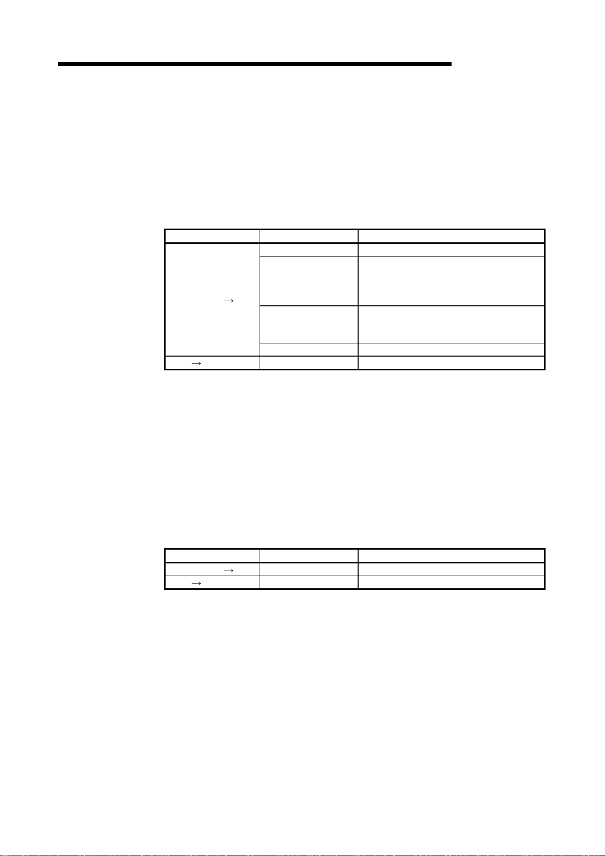
Manual Name
CC-Link System Master • Local Module type AJ61BT 11/A1SJ61BT11 User' s Manual
Describes the system configuration, performance specifications, functions, handling, wiring and troubleshooting of the AJ61BT11 and A1SJ61BT11. (Option)
CC-Link System Master • Local Module type AJ61QBT 11/A1SJ61QBT 11 User' s Manual
Describes the system configuration, performance specifications, functions, handling, wiring and troubleshooting of the AJ61QB11 and A1SJ61QBT11. (Option)
CC-Link System Master • Local Module type QJ61BT11 U ser’s Manual
Describes the system configuration, performance specifications, functions, handling, wiring and
troubleshooting of the QJ61BT11 (Option)
A985GOT/A975GOT/A970GOT/A960GOT User's Manual
Explains the specifications, general system configuration, component devices, part names, option unit
loading methods, installation and wiring methods, maintenance and inspection methods, and error codes
of A985GOT/A975GOT/A970GOT/A960GOT unit. (Option)
A950GOT/A951GOT/A953GOT/A956GOT User's Manual
Explains the specifications, general system configuration, component devices, part names, option unit
loading methods, installation and wiring methods, maintenance and inspection methods, and error codes
of A950GOT/A951GOT/A953GOT/A956GOT unit. (Option)
A870GOT Graphic Operation Terminal User's M anual
This manual describes the specifications and performance of the A870GOT main unit as well as the
hardware configuration, procedures for installing optional units, operation in off-line mode, error codes,
and troubleshooting guidelines. (Option)
Manual Number
(Model Code)
IB-66721
(13J872)
IB-66722
(13J873)
SH-080016
(13JL91)
SH-4005
(1DM099)
SH-080018
(1DM103)
IB-66628
(1DM050)
A850GOT Graphic Operation Terminal User's M anual
This manual describes the specifications and performance of the A850GOT main unit as well as the
hardware configuration, procedures for installing optional units, operation in off-line mode, error codes,
and troubleshooting guidelines. (Option)
IB-66669
(1DM038)
GT Works Version 5/GT Designer Version 5 Reference Manual
Deals with the system configuration of GT Works Version 5/GT Designer Version 5, the screen makeup
of the GT Designer, the general description of various monitoring functions, the procedure for displaying
the monitor screen on the GOT, and how to use the help function. (Option)
SH-080117
(1DM187)
GOT-A900 Series Operating Manual (GT Works Version 5/GT Designer Version 5
compatible Extended • Option Functions Manual)
Provides the specifications of the utility, system monitoring, ladder monitoring, special function unit
monitoring, network monitoring functions and list editor functions available for the GOT-A900 series and
how to operate the dedicated monitor screen. (Option)
SH-080118
(1DM185)
A - 8 A - 8
Page 10

Manual Name
GOT-A900 Series User's Manual (GT Works Version 5/GT Designer Version 5 comp atible
Connection System Manual)
Gives the specifications, system configuration, setting method and connection diagram of each
connection form available for the GOT-A900 series. (Option)
SW3NIW-A8GOTP Graphic Settings Software Package Operating Manual
(Monitor Screen Creation Manual)
This manual describes how to create monitor screens, the monitor functions available for the GOT, how
to set the monitor functions, precautions for creating monitor screens, and precautions for utilizing the
monitor data of the conventional GOT. (Option)
SW3NIW-A8GOTP Graphic Settings Software Package Operating Manual
(Data Transmission/Debugging/Document Creation M anual)
This manual describes the following items.
1) Procedures for downloading project data to the GOT and uploading it from the GOT.
2) Procedures for installing the operating system in the GOT.
3) Procedures for using the A8GOTP as a virtual programmable controller and for debugging the GOT.
4) Procedures for outputting created monitor data as a completed document (Option)
GOT800 Series Operating Manual (Expanded Functions Manual)
This manual describes the operation procedures for using the system monitor functions, monitor
functions for special function units, and the dedicated monitor screens used with the ladder monitor
functions. (Option)
Manual Number
(Model Code)
SH-080119
(1DM189)
IB-66793
(1DM176)
IB-66794
(1DM175)
IB-66796
(1DM181)
Type SW2IVD-GPPQ GPP Software package OPERATING MANUAL(Offline)
Describes the offline functions, such as the programming method, printout method and file maintenance,
of the SW2IVD-GPPQ (Option)
GX Developer Version 6 Operating Manual
Describes the online functions of GX Developer including the programming procedure, printing out
procedure, monitoring procedure, and debugging procedure. (Option)
Conformation to the EMC Directive
A8GT-J61BT15 conforms to the EMC Directive only when connected to the GOT
(with CE logo printed on the rating plate) which conforms to the EMC Directive.
For details of Conformation to the EMC Directive, refer to the using GOT User's
Manual (Hardware).
IB-66774
(13J921)
SH-080098
(13J989)
A - 9 A - 9
Page 11
Abbreviations and generic terms in this manual
The following addreviations and symbols are used in this manual.
Abbreviation/Generic Name/Term Description
CC-Link Abbreviation for the Control & Communication Link system
CC-Link
communication
module
GOT-A900
Series
GOT800
Series
Software
Drawing
Software
Personal computer Personal computer where the corresponding software package is installed
Master station Station which controls intelligent device, Local and Remote stations
Local station
Remote I/O station Slave station in the CC-Link system which can handle bit data only
Remote device station Slave station in the CC-Link system which can handle bit data and word data
Remote station Generic name for remote I/O and remote device stations
Intelligent device station
Master/local module
Master module
Local module
Cyclic transmission
Transient transmission Transmission method in which co mmu nication is made at any timing
RX Remote input
RY Remote output
RWw Remote register (write area)
RWr Remote register (read area)
A8GT-J61BT13 Abbreviation of A8GT-J61BT13 type CC-Link communication module
A8GT-J61BT15 Abbreviation of A8GT-J61BT15 type CC-Link communication module
A985GOT-V Generic term of A985GOT-TBA-V and A985GOT-TBD-V
A985GOT Generic term of A985GOT-TBA, A985GOT-TBD and A985GOT-TBA-EU
A975GOT
A970GOT
A97*GOT Generic term of A975GOT and A970GOT
A960GOT Generic term of A960GOT-EBA, A960GOT-EBD and A960GOT-EBA-EU
A956GOT
A956WGOT Abbreviation of A956WGOT-TBD
A870GOT
A810GOT Abbreviation of A8GT-10GOT-C
A850GOT
GT Works
Version 5
GT Designer
Version 5
GX Developer Generic term of SW
GT Designer Abbreviation of image creation software GT Designer for GOT900
NIW-
SW
A8GOTP
Generic term of A975GOT-TBA-B, A975GOT-TBD-B, A975GOT-TBA, A975GOTTBD and A975GOT-TBA-EU
Generic term of A970GOT-TBA-B A970GOT-TBD-B, A970GOT-TBA, A970GOTTBD, A970GOT-SBA, A970GOT-SBD, A970GOT-LBA, A970GOT-LBD, A970GOTTBA-EU and A970GOT-SBA-EU
Generic term of A956GOT-TBD, A956GOT-SBD, A956GOT-LBD, A956GOT-TBDM3, A956GOT-SBD-M3 and A956GOT-LBD-M3
Generic term of A8GT-70GOT-EW, A8GT-70GOT-EB, A8GT-70GOT-SW, A8GT70GOT-SB, A8GT-70GOT-TW, A8GT-70GOT-TB
Abbreviation of A850GOT-LWD, A850GOT-LBD, A850GOT-SWD, A850GOT-SBD,
A850GOT-LWD-M3, A850GOT-LBD-M3, A850GOT-SWD-M3, A850GOT-SBD-M3
Abbreviation of SW5D5C-GTWORKS-E software package
Generic term of SW5D5C-GOTR-PACKE software package and SW5D5C-GOTR-
PACKEV software package
D5C-GPPW-E/SW D5F-GPPW-E software packages
Abbreviation of SW
Station which has a CPU and can communicate with the Master and other Local
stations
Slave station in the CC-Link system which can make transient transmission, such
as the A8GT-J61BT13
Generic name for the QJ61BT11, AJ61BT11, AJ61QBT11, A1SJ61BT11 and
A1SJ61QBT11
Generic name for the QJ61BT11, AJ61BT11, AJ61QBT11, A1SJ61BT11 and
A1SJ61QBT11 when used as the Master station
Generic name for the QJ61BT11, AJ61BT11, AJ61QBT11, A1SJ61BT11 and
A1SJ61QBT11 when used as Local stations
Transmission method in which the cont ents of the remote inputs/outputs and
remote registers are updated periodically
NIW-A8GOTP software package
A - 10 A - 10
Page 12
1 OVERVIEW
1. OVERVIEW
MELSEC-GOT
This user's manual includes specifications, monitoring method, handling information,
programming method and other instructions of the A8GT-J61BT15 CC-Link
communication module (hereinafter referred to as the "A8GT-J61BT15") used in the
Control Communication Link (hereinafter referred to as "CC-Link") system.
By connecting the A8GT-J61BT15 module to the GOT, it can perform a monitoring
operation as an remote device station (the number of occupied stations may be
selected between 2 and 4) in the CC-Link system.
Remote device stat i o n
GOT's remote inputs/outputs and remote registers assigned to
the Master station by CC-Link parameter setting can be monitored.
1
Local station Master station
Intelligent device station
CC-Link dedicated
cable
Monitoring
methods
Devices that can
be monitored
(1) PLC CPU that allows monitoring
When the A8GT-J61BT15 is used, the following CPUs can be monitored.
• QCPU (Q mode)
• QCPU (A mode)
• QnACPU
• ACPU
• Motion controlle r CP U
(2) Difference between the A8GT-J 61B T13 and th e A8G T-J 61BT15
There are differences in the monitoring methods that can be used as well as the
devices that can be monitored between the A8GT-J61BT13 and the A8GTJ61BT15.
The following table lists these differences between the A8GT-J61BT13 and the
A8GT-J61BT15.
: Usable :Unusable
Item
Monitoring by Cyclic Transmission
Monitoring by Transient Transmission
The GOT’s remote inputs/outputs and
remote registers assigned to the Master
station.
All remote inputs/outputs and remote
registers assigned to the Master station.
When the A8GT-J61BT13
is used
When the A8GT-J61BT15
is used
1 - 1 1 - 1
Page 13

1 OVERVIEW
MEMO
1
MELSEC-GOT
1 - 2 1 - 2
Page 14
2 SYSTEM CONFIGURATION
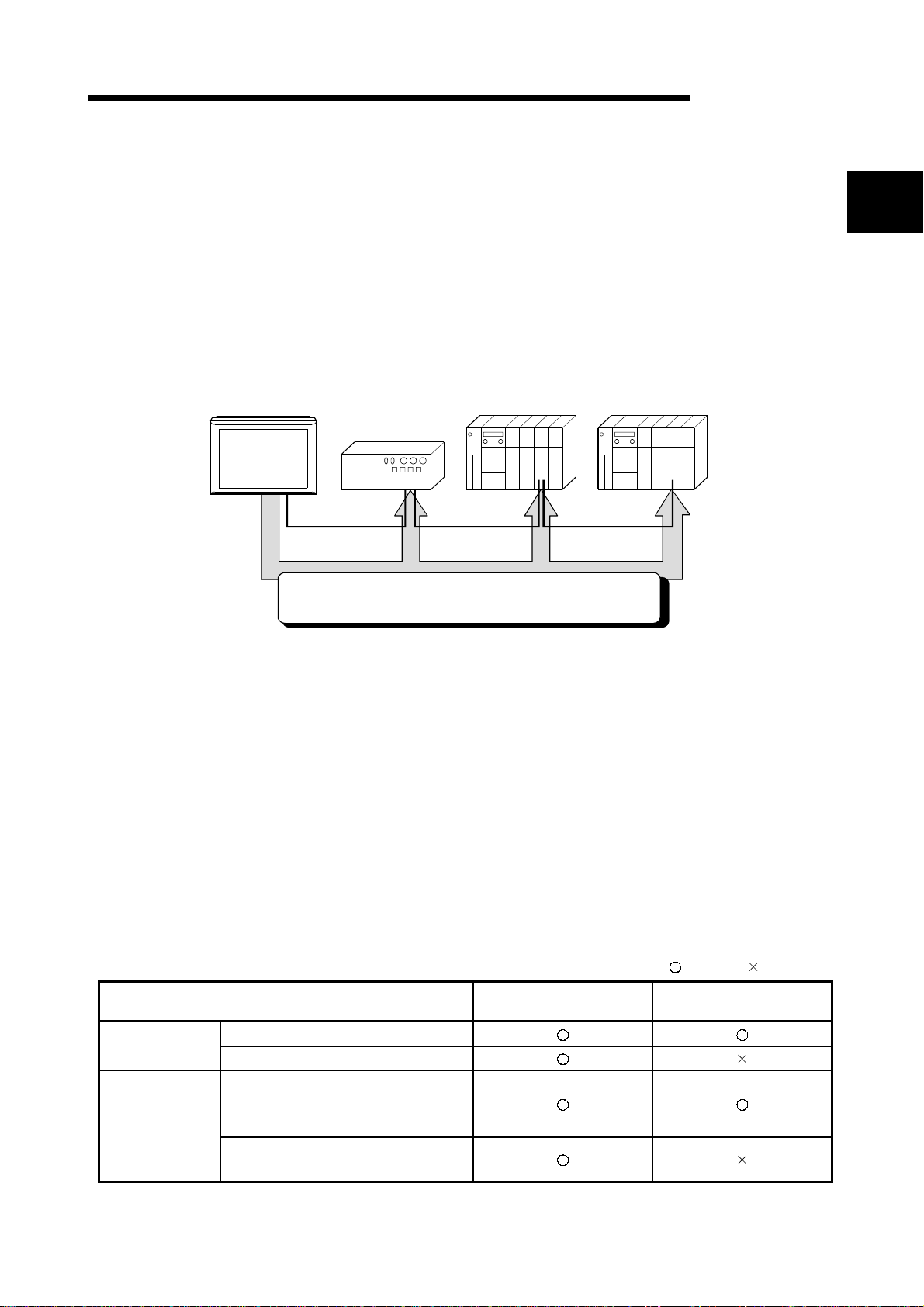
2. SYSTEM CONFIGURATION
This chapter describes the system configuration of the whole CC-Link system where
the A8GT-J61BT15 is used.
For equipment required for the GOT, refer to the user's manual of the GOT used.
MELSEC-GOT
2.1 Overall Configuration
The following diagram shows the overall configuration for use of the A8GT-J61BT15.
Up to 32 GOTs using the A8GT-J61BT15 may be connected in relation to one master
module.
CC-Link Master/local module (Ma ste r station)
Terminal resistor
Terminal resistor
(Intelligent device station)
The number of occupied stations may be
selected between 2 and 4.
Remote inputs/outputs 64/128 points each
Remote registers 8/16 points each
GOT + A8GT-J61BT15
(Remote device station)
2
CC-Link Master/local module (Lo cal s tation )
CC-Link dedicated cable
(Remote I/O station)
2 - 1 2 - 1
Page 15
2 SYSTEM CONFIGURATION
2.2 Instructions for System Configuration
When using the A8GT-J61BT15, follow these system configuration instructions.
(1) GOTs which can use the A8GT-J61BT15
The following GOT models can use the A8GT-J61BT15.
Name Model
2
A985GOT-V A985GOT-TBA-V, A985GOT-TBD-V
A985GOT A985GOT-TBA, A985GOT-TBD
A975GOT A975GOT-TBA(-B), A975GOT-TBD(-B)
A970GOT
A960GOT A960GOT-EBA, A960GOT-EBD
A956WGOT A956WGOT-TBD
A956GOT A956GOT-TBD(-M3), A956GOT-SBD(-M3), A956GOT-LBD(-M3)
A870GOT
A850GOT
MELSEC-GOT
A970GOT-TBA(-B), A970GOT-TBD(-B), A970GOT-SBA,
A970GOT-SBD, A970GOT-LBA, A970GOT-LBD
A8GT-70GOT-E W,A8GT - 70GOT-EB,A8GT-70GOT-SW,A8GT70GOT-SB, A8GT- 70GOT-TW,A8GT-70GOT - TB
A850GOT-LWD(-M3),A850GOT-LBD(-M3),A850GOT-SWD(-M3),
A850GOT-SBD(-M3)
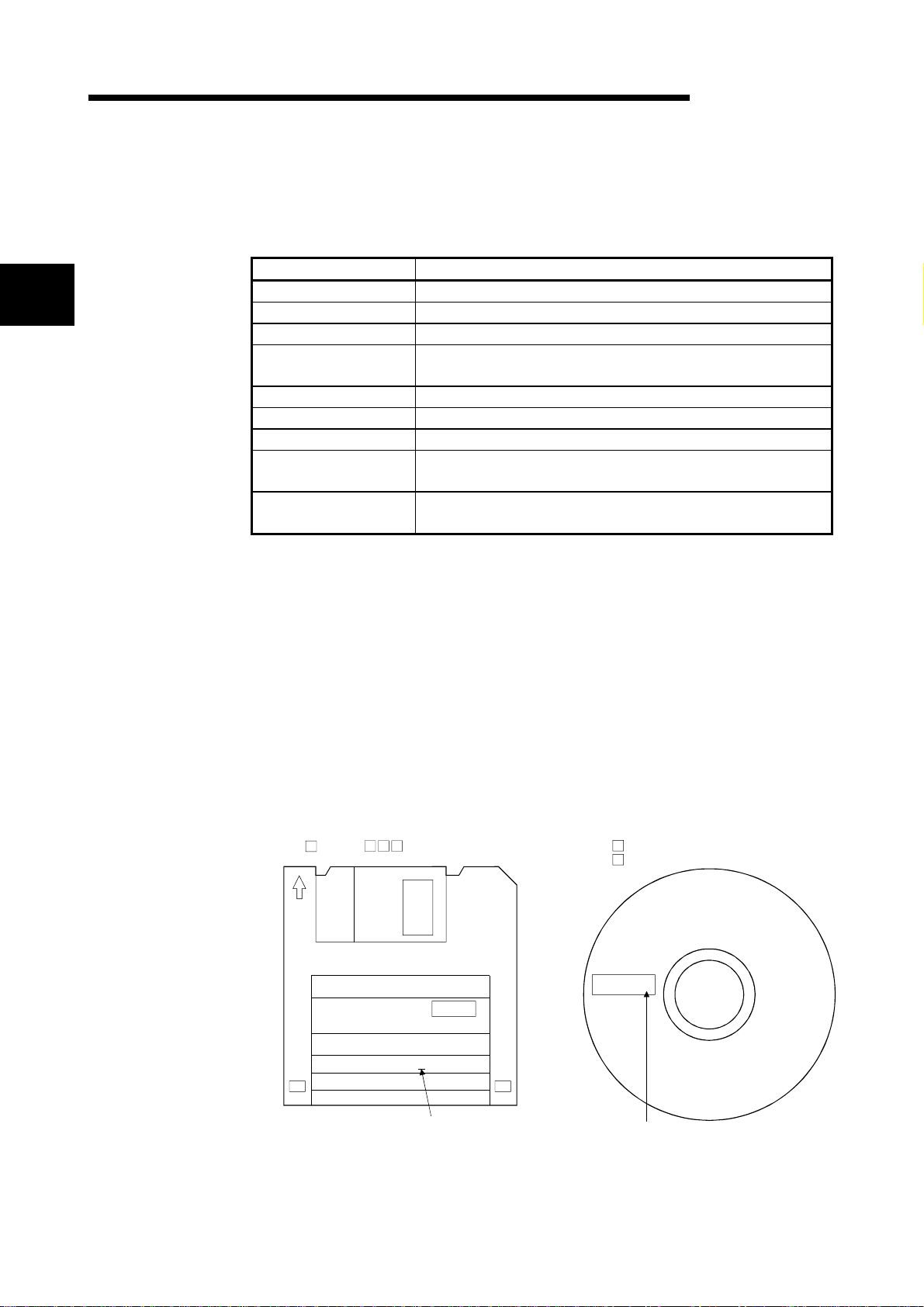
(2) Compatible software version
When creating the GOT screen or installing the operating system (OS), always use
the following software versions.
(a) GOT-A900 Series
SW0D5C-GTWORKS-E software version A or later
SW1D5C-GOTRE-PACK software version A or later
(b) GOT800 Series
Graphics software: SW3NIW-A8GOTP software version A or later
OS program: SW3NIW-A8SYSP software version A or later
Special module monitor data: SW3NIW-A8GMDP
The software version can be confirmed on the rating plate of the floppy disk of
the product.
SW NIW-A8 P SW D5C-GTWORKS-E or
SW D5C-GOTR-PACKE
DATE
MITSUBISHI
MELSEC
SOFTWARE PACKAGE
MODEL SW3NIW-A8GOTP
DATE 9801A E 1/6
3.5inch
9806A A
Indicates the software version.
Indicates the software version.
2 - 2 2 - 2
Page 16
2 SYSTEM CONFIGURATION
(3) Communication Driver Installed in the GOT
Install the following communication driver in the GOT.
CC-Link communication unit Used Driver to Be Installed
(4) Utility function
The following t abl e list s th e GOT’s utility fun cti on s th at can be used wh en the
A8GT-J61BT15 is in use.
Utility function
: CPU communications check of the self-test function cannot be performed when
the GOT800 Series are in use.
MELSEC-GOT
A8GT-J61BT15 CC-LINK (RD)
: Usable : Unusable
Item When the A8GT-J61BT15 is used
Brightness/contrast adjustment
Screen & OS copy
Setup
Self-test
Memory information
Clock
Screen cleanup
Password
(5) Extended•option functions
Refer to the manuals listed in the table below for the GOT’s extended • option
functions that can be used when the A8GT-J61BT15 is in use.
GOT Used Manuals to refer to
GOT-A900 Series
GOT800 Series GOT800 Series Operating Manual (Expended Functions Manual)
GOT-A900 Series Operating Manual (GT Works Version5/GT
Designer Version5 compatible Extended•Option Functions Manual)
2 - 3 2 - 3
Page 17

3 SPECIFICATIONS
3. SPECIFICATIONS
This chapter provides the general and performance specifications and other
information of the A8GT-J61BT15.
3.1 General Specifications
The general specifications of the A8GT-J61BT15 changes according to the GOT used.
Refer to the user's manual of the GOT used.
3.2 Performance Specifications
3
The following table lists the performance specifications of the A8GT-J61BT15.
Item Specifications
CC-Link station type Remote device station
Number of stations occupied
Monitor device
Transmission speed 156kbps/625kbps/2.5Mbps/5Mbps/10Mbps
Max. transmission distance Depends on the transmission speed.
Max. number of modules
connected
Connection cable CC-Link dedicated cable
Terminal block 8-pin terminal block (M3.5 8 screws)
Applicable cable size 0.75mm2 to 2.00mm
Applicable crimping terminal RAV1.25-3, RAV2-3.5 (conforming to JIS C2805)
Current consumption 100mA
Outline dimensions 99mm(3.9inch)(H) 149mm(5.85inch)(W) 34mm(1.34 inch)(D)
Weight 0.20kg (0.44lb)
Compatible software package
2
1 Each of the I/O signals (RX, RY) occupies 16 points of a system area within device points.
For more details on the I/O signals, refer to Section 4.3.1.
2 Be sure to use a software package that supports the GOT to be used.
For more information on the software packages that support the GOT, refer to the user’s manual of the GOT to be used.
MELSEC-GOT
May be selected between 2 and 4.
2 station: RX/RY 64 points each
4 stations: RX/RY 128 points each
Write from GOT:RX,RWs assigned to the GOT (depending on the number of stations occupied(Refer
to upper))
Resd to GOT : RX,RWs assigned to the GOT (depending on the number of stations
occupied(Refer to upper))
32 (when two stations are selected)
The max. number of modules connected depends on the configuration of the CC-Link system to be used .
For more details on the max. number of modules connected, refer to the CC-Link System MasterLocal Module User’s Manual.
GOT-A900 Series
SW0D5C-GTWORKS-E Ve r sio n A or la te r
SW0D5C-GOTRE-PACK Version A or later
GOT800 Series
SW3NIW-A8GOTP Version A or later
SW3NIW-A8SYSP Version A or later
SW3NIW-A8GMDP
1, RW write area 8 points each/read area all area
1, RW write area 16 points each /read area all area
2
3 - 1 3 - 1
Page 18

3 SPECIFICATIONS
MEMO
MELSEC-GOT
3
3 - 2 3 - 2
Page 19

4 MONITORING SPECIFICATION
4. MONITORING SPECIFICATION
4.1 Monitoring Overview
When the A8GT-J61BT15 is used, the GOT has the following two monitoring methods.
Monitor Method Normal Monitor Dedicated Command Monitor
The remote inputs/outputs and remote registers
Description
of the GOT assigned to the remote device
station in the CC-Link parameter setting are
specified and monitored.
4
Advantage Data update processing speed is high.
As the remote register assignment area of the
Disadvantage
GOT is small, the number of devices that can
be displayed on one screen is small.
MELSEC-GOT
The remote register area is used as the GOT
internal device transfer command area to
specify and monitor the GOT internal devices.
Data update processing speed is high.
Since a dedicated command is executed to
develop data in the GOT internal word devices
(GD0 to GD1023), multiple pieces of
information, such as the operating status,
production and operation directives, can be
monitored within one screen.
(The number of devices that can be displayed
on one screen is larger than that of normal
monitor.)
A sequence program is needed to execute the
dedicated command.
4 - 1 4 - 1
Page 20
4 MONITORING SPECIFICATION
2
3
(1) Normal monitor method
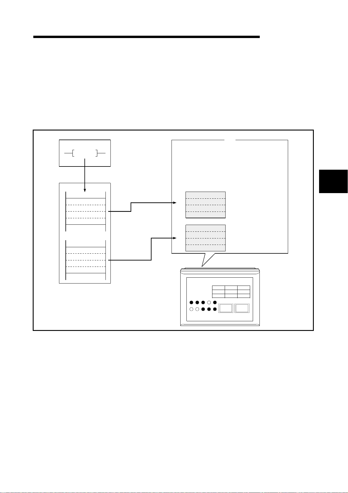
In the monitor overview, the remote outp ut and remote register
(write area) are described
separately from the remote input an d remote register (read area),
but all of the information
can be displayed on one screen for monitor i ng .
Monitor for remote output and remot e r eg i ster (wri te ar ea)
MELSEC-GOT
PLC CPU
TO
Master
station
RY
RWw
1) Using the sequence program, the data is stored
in the remote output (RY) and the remote register
(RWw) of GOT's allocated to the master station.
) Data is stored in the GOT's remote output
and re-mote register by link scan.
) The specified remote output and remote register
aremonitored.
1)
2)
2)
The monitor point depending on the number of
occupied stations setting.
When 2 stations are set
RYn0 to RY(n+2)F:48 points
RWwm to RWwm+7:8 points
When 4 stations are set
RYn0 to RY(n+6)F:112 points
RWwm to RWwm+F:16 points
RY
RWw
GOT
3)
Line1
500
350
100
450
400
100
Line2
Line3
4
4 - 2 4 - 2
Page 21
4 MONITORING SPECIFICATION
2
3
Monitor (write from GOT) for remote input and remote register (read area)
MELSEC-GOT
PLC CPU
FROM
Master
station
RX
RWr
3)
2)
2)
1) The data is stored in the GOT's remote input
(RX) and remote register (RWr).
(Touch switch function, numeric value input function,etc.)
) By link scan, the data is stored in the remote input
and remote register allocated to the master station GOT.
(Collected for each link scan.)
) Remote input and remote register data are read to
the PLC CPU.
3)
Line1
Line2
Line3
GOT
100
050400
100
The monitor point vary depending on the number of
occupied stations setting.
When 2 stations are set
RYn0 to RY(n+2)F:48 points
RWrm to RWrm+7:8 points
When 4 stations are set
RYn0 to RY(n+6)F:112 points
RWrm to RWrm+F:16 points
RX
RWr
POINT
The GOT can input (e.g. touch key function) data to only the remote inputs (RX)
and remote registers (RWr) assigned the master station.
It cannot input (e.g. touch key function) or display (e.g. lamp display function) data
to the other remote inputs (RX) and remote registers (RWr).
4 - 3 4 - 3
Page 22
4 MONITORING SPECIFICATION
(
)
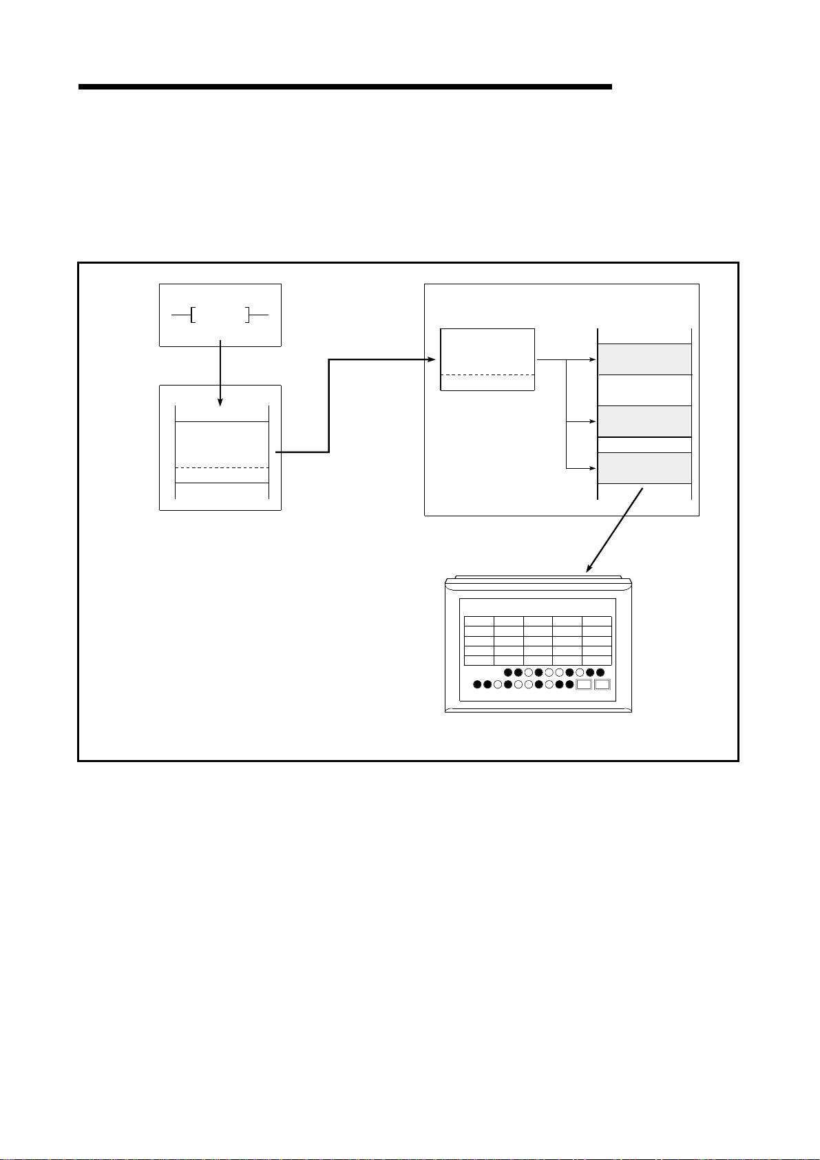
(2) Dedicated command monitor method
The remote register (write area) data is stored in the GOT internal device using
dedicated commands and monitoring is performed.
Refer to Section 4.5 for the dedicated commands.
When the GOT internal device write command i s executed
MELSEC-GOT
PLC CPU
TO
Master
station
1)
2)
RW
Write command
White data
1) Using the sequence program, store the write command
and the write data to be stored in the GOT internal de-vice
to the remote register (RWw) of the GOT allo-cated
to the master station.
2) When the GOT request flag is turned on, the write com-mand
data and write data are stored in the GOT
remote registers, and the write data is stored in the
GOT internal device.
3) The data in the GOT internal device where the write
data is stored is monitored.
Repeat steps 1) and 2) to execute the write command,
and write several information to the GOT internal de-vice
and monitor the data.
GOT
RWw
Write command
White data
Repeat storing write
command and expand (write)
data, and write to the GOT
internarl device.
Monitor production amount
Production
Line
quantity
1
190
2
200
3
450
4
550
Operating
infomation
The openrating information and
production amount are monitored
with GOT.
Monitor GD.
Planed
quantity
500
400
700
600
Fated
quantity
GD
Success
Rate
7
30%
6
50%
23
75%
22
85%
GOT Internal decice
Write data1 (Operating
Information data)
Write data2 (Production
quantity data)
Write data1 (Operating
Information data)
3)
4 - 4 4 - 4
Page 23

4 MONITORING SPECIFICATION
5
When the GOT internal device read command i s executed
MELSEC-GOT
PLC CPU
TO
FORM
Master
2)
3)
station
RWw
Read command
)
RWr
Read data
4)
1) Write the data (such as operation command data) from GOT
to the GOT internal device.
2) Using the sequence program, st ore the read command data
to the remote register (RWw).
3) When the GOT request flag is turned on, the read com-mand
data is stored in the GOT remote register(RWw),
and the data in the specified GOT internal device is read to
the remote device(RWr).
4) By link scan, the data is stored in the remote device(RWr)
of the GOT allocated to the master station.
5) Using the sequence program, read the remote device(RWr)
data to the PLC CPU.
Repeat the above steps and execute the read commands,
then read several information to the PLC CPU.
GOT
Repeat storing the read command data, and read from
GOT internal device data.
RWw
Read command
3)
GOT internal device
GD
Read data1 (Operating
command data)
RWr
Read data
Read data2 (Operating
command data)
Read data3 (Operating
command data)
1) Set the operation specification
data with GOT.
Planned quantly selling
Line2
Line3
Line4
PartsA
PartsB
PartsC
PartsD
100
100
250
300
200
50
0
300
Line5
100
0
0
0
Touch switch function
and numeric value
input function
0
0
0
4 - 5 4 - 5
Page 24

4 MONITORING SPECIFICATION
MELSEC-GOT
4.2 Monitorable Access Range and Device Specifyi ng Method
4.2.1 Monitorable access range
The GOT can monitor only the remote inputs/outputs and remote registers (read/write
area) of the GOT assigned to the master station and the internal devices of the GOT.
The devices that can be monitored are indicated below.
Setting Device Range
Monitorable Devices
Remote inputs (RX)
Remote outputs (RY)
Bit
Word
Specified bits (RWw) of remote registers (write area) RWwm to RWwm+7 RWwm to RWwm+F
Specified bits (RWr) of remote registers (read area) RWrn to RWrn+7 RWrn to RWrn+F
GOT bit register (GB)
Bit designation of GOT data register (GD) GD64 to GD1023
Remote registers (write area) (RWw)
Remote registers (read area) (RWr) RWrn to RWrn+7 RWrn to RWrn+F
GOT data register (GD)
Converting GOT bit register to word (GB) 1 GB64 to GB1023
GOT special register (GS)
1
1 Can be monitored only when the GOT-A900 Series is used.
2 n and m in the table indicate the addresses assigned to the master station by station number setting.
Number of occupied
stations:2 station
Number of occupied
stations:4 station
RXn0 to RX(n+3)F RXn0 to RX(n+7)F
RYn0 to RY(n+3)F RYn0 to RY(n+7)F
GB64 to GB1023
RWwm to RWwm+7 RWwm to RWwm+F
GD64 to GD1023
GS0 to GS511
POINT
Dedicated command monitor is enabled for the GOT data registers (GD) only.
4.2.2 How to specify devices when creating the monitor scr een
When creating the monitor screen, set the following devices as the devices to be
specified.
(1) Setting of NW number and PLC station number
Set "NW number to 0" and "PLC station number to host station".
(2) Setting of device names and device numbers
Set the follow in g dev i ce na mes.
As the device numbers of the remote inputs/outputs and remote registers, set the
addresses assigned by station number setting.
Device to Be Monitored
Remote inputs (RX) X X0 to X7FF
Remote outputs (RY) Y Y0 to Y7FF
Remote registers (write area) (RWw) Ww Ww0 to WwFF
Remote registers (read area) (RWr) Wr Wr0 to WrFF
Device Name Set
on Graphics Software
Setting Device Range
4 - 6 4 - 6
Page 25

4 MONITORING SPECIFICATION
4.3 I/O Signals to the Master Module
4.3.1 List of I/O signals
The I/O signal allo cat io n i s show n below.
The I/O signals varies depending on the set number of occupied stations (2 stations or
4 stations).
The "n" in the table indicates the address allocated to the master module by the station
number setting.
(1) When monitoring usi ng the normal moni tor meth od
Signal Direction : GOT Master module Signal Direction : Master module GOT
Device number Device number
Number of occupied stations Number of occupied stations
2 station 4 stations
RXn0 to
RX(n+2) F
RX(n+3)0 to
RX(n+3) A
RX(n+3)B RX(n+7)B Remote ready *1
RX(n+3)B to
RX(n+3) F
RXn0 to
RX(n+6) F
RX(n+7)0 to
RX(n+7) A
RX(n+7)B to
RX(n+7) F
Signal name
User area
Unusable
Unusable
2 station 4 stations
RYn0 to
RY(n+2)F
RY(n+3)0 to
RY(n+3)F
RYn0 to
RY(n+7)0 to
RY(n+6)F
RY(n+7)F
MELSEC-GOT
Signal name
User area
Unusable
*1 The remote ready flag turns ON at GOT power-on, at hardware reset, or when the
GOT is in an operable state.
If the GOT has been powered on, the flag is OFF during offline operation (OS
installation, screen data downloading) or during initial processin g execution.
Use this flag in an interlock ladder for write/read performed from the CC -Link master
station.
4 - 7 4 - 7
Page 26

4 MONITORING SPECIFICATION
MELSEC-GOT
(2) When monitoring using the dedi cated monitor m ethod
Signal Direction : GOT Master module Signal Direction : Master module GOT
Device number Device number
Number of occupied stations Number of occupied stations
2 station 4 stations
RXn0 to
RX(n+2) F
RX(n+3)0 RX(n+7)0 GOT complete flag RY(n+3)0 RY(n+7)0 GOT request flag
RX(n+3)1 to
RX(n+3)8
RX(n+3)9 RX(n+7)9 Initial data setting complete flag RY(n+3)9 RY(n+7)9 Initial data setting request flag
RX(n+3)A RX(n+7)A Error status flag RY(n+3)A RY(n+7)A Error reset request flag
RX(n+3)B RX(n+7)B Remote ready *1 RY(n+3)B RY(n+7)B
RX(n+3)C to
RX(n+3) F
RXn0 to
RX(n+6) F
RX(n+7)1 to
RX(n+7)8
RX(n+7)C to
RX(n+7) F
Signal name
User area
Unusable
Unusable
Signal name
2 station 4 stations
RYn0 to
RY(n+2)F
RY(n+3)1 RY(n+7)1 GOT monitor request flag
RY(n+3)2 RY(n+7)2 GOT always write request flag
RY(n+3)3 to
RY(n+3)8
RY(n+3)C to
RY(n+3)F
RYn0 to
RY(n+6)F
RY(n+7)3 to
RY(n+7)8
RY(n+7)C to
RY(n+7)F
User area
Unusable
Unusable
DANGER
*1 The remote ready flag turns ON at GOT power-on, at hardware reset, or when the
GOT is in an operable state.
If the GOT has been powered on, the flag is OFF during offline operation (OS
installation, screen data downloading) or during initial processin g execution.
Use this flag in an interlock ladder for write/read performed from the CC -Link master
station.
• Do not output the reserved signals among the output signals provided from the
master module to the GOT.
If any of the reserved signals is output, the PLC system may malfunction.
4 - 8 4 - 8
Page 27

4 MONITORING SPECIFICATION
g
4.3.2 Details of the I/O signals
The function o f each I/ O signal is described bel ow
(1) GOT complete flag (RX(n+3)0, RX(n+7)0), and GOT req uest flag
(RY(n+3)0, RY(n+7)0)
By turning on the GOT request flag, each command which uses the GOT internal
device to monitor (excluding the initial setting command, monitor request
command, and always write request command) is executed.
After each command processing is complete, the GOT complete flag turns on.
When the GOT request flag is turned off, the GOT complete flag turns off as well.
To instruction
GOT request flag
MELSEC-GOT
Command data storage
ON
Command
GOT compete flag
Command processing
ON
(2) Initial data setting complete flag ( RX ( n+3)9,R X (n+7) 9), and i ni ti al
data setting request flag (RY(n+3),RY( n+ 7)9)
By turning on the initial data setting request flag, the initial setting command to
monitor using the GOT internal device, is executed.
When the initial setting command processing is complete, the initial data setting
complete flag turns on.
When the initial data setting request flag is turned off, the initial data setting
complete fl ag tu rn s o ff a s w ell .
To instruction
Initial data setting request flag
Initial setting command
Initial data setting compete fla
Command data storage
ON
Command processing
ON
POINT
When performing dedicated command monitor, the initial data setting request flag
must be turned ON to execute the initial setting command.
Refer to Section 4.6.1 for the initial setting command.
4 - 9 4 - 9
Page 28

4 MONITORING SPECIFICATION
G
p
(3) GOT monitor request flag (RY(n+3)1,RY(n+7)1)
When the GOT monitor request flag is on, the data in the GOT internal device
registered for monitoring is always read to the remote register.
Refer to (a) when executing the monitor registration command.
GOT monitor request flag
MELSEC-GOT
ON
Monitor re quest comma nd
Command processing
Command processing Command processing Command processing
Processes to always read the data in the GOT
internal device specified in the remote register
(4) GOT always write request flag (RY ( n+ 3)2,RY ( n+ 7)2)
When the GOT always write request flag is on, the remote device data is always
written to the GOT i nt e rnal devi ce whi ch ha s be en re gi st ere d for w rite .
Refer to (a) when executing the always write register command.
ON
OT always write request flag
GOT write request command
Command processing
Command processing Command processing Command processing
Processes to always read the remote register
data to the s
ecified GOT internal device.
(5) Error status flag (RX(n+3)A,RX(n+7)A) and error reset request flag
(RY(n+3)A,RY(n+7)A)
If an error occurs during execution of a command when communicating with the
GOT internal device, the error status flag turns on.
The error status flag is turned off by turning on the error reset request flag,.
ON
Error status flag
Error reset request flag
ON
POINT
The error status flag turns ON if the executed dedicated command is wrong or the
preset devi ce ca nno t be mon it o red (t he devi ce is ou t side the mon it o r- e nabl ed
range).
(6) Remote ready flag (RX(n+ 3) B,RX(n+ 7) B)
Turns on during the GOT startup.
Turns off during off-line operations (OS installation and screen data download)
and initial processing execution.
4 - 10 4 - 10
Page 29
4 MONITORING SPECIFICATION
MELSEC-GOT
4.4 Remote Register Allocation
The remote regist er all o cati on fo r GOT is de scrib ed bel ow .
The usage of the remote registers is different between the normal monitor method and
dedicated command monitor method.
The "m" and "n" in the table indicates the address allocated to the master module by
the station numbe r se tt ing.
(1) When the normal monitor method
The entire area is used for user region.
Addresses
Number of occupied stationsTransfer Direction
2 station 4 stations
Master station GOT RWwm to RWwm+7 RWwm to RWwm+F User write area 0
GOT Master station RWrn to RWrn+7 RWrn to RWrn+F User read area 0
Description Default Value
(2) When the dedicated command monitor metho d
The entire area is used for the GOT internal device communication commands.
Refer to Section 4.5 regarding each command for the GOT internal device
communication.
Addresses
Transfer Direction
Master station GOT RWwm to RWwm+7 RWwm to RWwm+F
GOT Master station RWrn to RWrn+7 RWrn to RWrn+F
Number of occupied stations
2 station 4 stations
Description Default Value
Command execution area
to be monitored by using
GOT internal device
Command response area
to be monitored by using
GOT internal device
0
0
4 - 11 4 - 11
Page 30

4 MONITORING SPECIFICATION
4.5 Command List for the Dedicated Comm and M oni tor Method
The command list for the dedicated command monitor is shown below.
Command name Contents Reference Section
Initial setting command when monitoring with dedicated
Initial setting
Continuous read
Random read
Continuous write
Random write
Monitor register
Monitor request
Always write register
Always write request
command monitor method (monitoring is performed using
the GOT internal device).
Command to read the specified number of points of data
from the specified head GOT internal device to the remote
register.
Maximum read points
When the number of stations is set to 4 stations: 14 points
When the number of stations is set to 2 stations: 6 points
Command to read data from several different GOT internal
devices to the remote register.
Maximum read points
When the number of stations is set to 4 stations: 14 points
When the number of stations is set to 2 stations: 6 points
Command to write specified number of points of data from
the remote register to the specified head GOT internal device.
Maximum write points
When the number of stations is set to 4 stations: 14 points
When the number of stations is set to 2 stations: 6 points
Command to write remote register data to several different
GOT internal devices.
Maximum write points
When the number of stations is set to 4 stations: 7 points
When the number of stations is set to 2 stations: 3 points
Command to register the GOT internal device number that
performs the always remote register read command.
Maximum registration points
When the number of stations is set to 4 stations: 14 points
When the number of stations is set to 2 stations: 6 points
Command to always read the GOT internal device data
stored by executing the monitor register command to the
remote register.
Command to always register the GOT internal device
number of the GOT internal device that performs the always
remote register data write command.
Maximum registration points
When the number of stations is set to 4 stations: 14 points
When the number of stations is set to 2 stations: 6 points
Command to always write remote register data to the GOT
internal device registered by executing the always write
register command.
MELSEC-GOT
Section 4.6.1
Section 4.6.2
Section 4.6.3
Section 4.6.4
Section 4.6.5
Section 4.6.6
Section 4.6.7
Section 4.6.8
Section 4.6.9
4 - 12 4 - 12
Page 31

4 MONITORING SPECIFICATION
4.6 Details of Each Command
The execution method for each command is described.
The following system example is used to describe the sequence program in this section.
Refer to the CC-Link Master Module User's Manual regarding the sequence program
for the entire CC-Link system.
MELSEC-GOT
CPU
Master
unit
GOT
Station No. : 1 station
Number of
stations occupied : 2 station setting
Relationship among the PLC CPU, master station buffer memory, and remote device
stations
PLC CPU
M0 to M15
M16 to M31
M32 to M47
M48 to M63
M100 to M115
M116 to M131
M132 to M147
M148 to M163
D100
D101
D102
D103
D104
D105
D106
D107
D200
D201
D202
D203
D204
D205
D206
D207
Address
E0
E1
E2
E3
Address
160
161
162
163
Address
1E0
1E1
1E2
1E3
1E4
1E5
1E6
1E7
Address
2E0
2E1
2E2
2E3
2E4
2E5
2E6
2E7
Master station
Remote input (RX)
RX00 to RX0F
H
H
RX10 to RX1F
RX20 to RX2F
H
H
RX30 to RX3F
Remote output (RY)
RY00 to RY0F
H
RY10 to RY1F
H
RY20 to RY2F
H
H
RY30 to RY3F
Remote regist e r (R Ww )
(Write area)
H
H
H
H
H
H
H
H
H
H
H
H
H
H
H
H
RWw0
RWw1
RWw2
RWw3
RWw4
RWw5
RWw6
RWw7
Remote regis te r (RW r )
(Read area)
RWr0
RWr1
RWr2
RWr3
RWr4
RWr5
RWr6
RWr7
GOT
(Remote device starion)
Remote input (RX)
RX00 to RX0F
RX10 to RX1F
RX20 to RX2F
RX30 to RX3F
Remote output (RY)
RY00 to RY0F
RY10 to RY1F
RY20 to RY2F
RY30 to RY3F
Remote regist e r (R Ww )
(Write area)
RWw0
RWw1
RWw2
RWw3
RWw4
RWw5
RWw6
RWw7
Remote regist e r ( R Wr )
(Read area)
RWr0
RWr1
RWr2
RWr3
RWr4
RWr5
RWr6
RWr7
4 - 13 4 - 13
Page 32

4 MONITORING SPECIFICATION
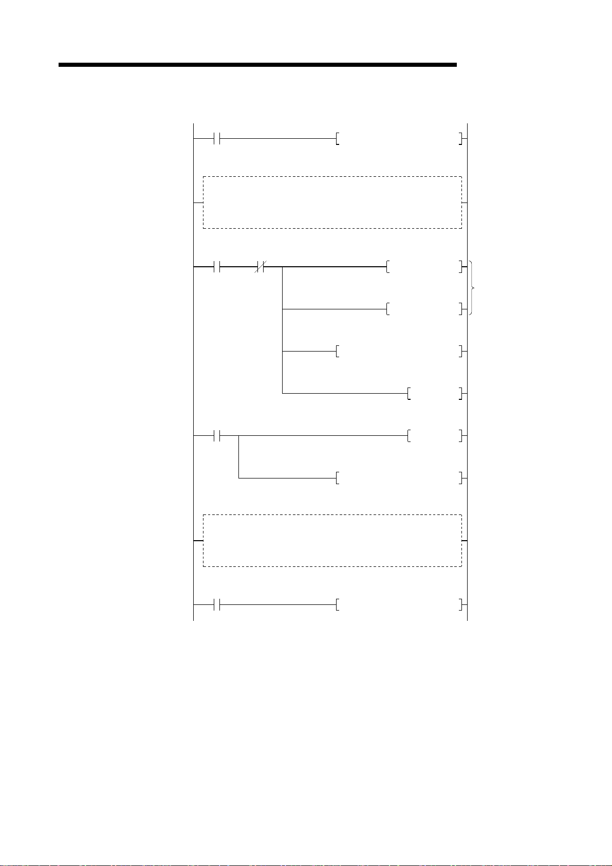
4.6.1 Initial setting command (1) Initial setting command
This is the initial setting command for monitoring with the GOT internal device.
Create a sequence program for initial setting command to be processed before
the commands described in Section 4.6.2 and after are executed.
(2) Command format
Transfer Direction Addresses Write data
Master station GOT
GOT Master station RWrn to RWrn + F
(3) Communication overv i ew
PLC CPU
RWwm (Higher byte) 1: Initial setting
1: Monitoring by the dedicated command monitor
RWwm (Lower byte)
RWwm + 1 to R Ww m + F
Master station
remote register
method
2: Switch to the normal monitor method
MELSEC-GOT
———
———
GOT
remote register
TO
1) 2)
RWw0
0101
H
RWw0
0101
H
1) Store the initial setting command data in the master station's remote register
(RWw).
2) Turn on the initial data setting request flag and store the command data in the
GOT remote register (RWw).
(Command execution)
The initial data setting complete flag turns on when the command processing
is complete.
By executing this command, the GOT will be in the monitor status with the
dedicated command monitor method.
4 - 14 4 - 14
Page 33

4 MONITORING SPECIFICATION
(4) Sequence program exampl e
Always ON
Remote
command
ready flag
M59
MELSEC-GOT
FROM H0 HE3 K4M48 K1 Remote input (RX) read
Error
status flag
M58
MOV H0101 D100 Command data storage
TO H0 H1E0 D100 K1 Transfers master station RWw0
Initial processing complete flag
M57
(ON at processing complete)
Other command execution program
Always ON
SET M157
RST M157
TO H0 H163 K4M148 K1 Remote o u tpu t (RY) write
Initial processing request flag ON
(command execution)
4 - 15 4 - 15
Page 34

4 MONITORING SPECIFICATION
4.6.2 Continuous read command (1) Continuous read command
This is a command to read data for a specified number of points from the
specified head GOT inte rn al devi ce to th e re mot e regi ste r.
(2) Command format
Transfer Direction Addresses Write data
Master station GOT
GOT Master station
RWwm (Higher byte) 2: Continuous read setting
When the occupied points are 2 stations
RWwm (Lower byte)
1 to 6 : GOT internal device point to be read
When the occupied points are 4 stations
1 to 14 : GOT internal device point to be read
RWwm + 1
RWwm + 2 to R Ww m + F
RWrn to RWrn + D
RWrn + E, RWrn + F
0 to 1023 : Head GOT internal device numbers to
be read
———
Stores the data to be read from the GOT internal
device
———
MELSEC-GOT
(3) Communication overv i ew
When reading three points from the GOT internal device GD100 to the remote
register (RWr)
RWw0
RWw1
RWr0
RWr1
RWr2
Master station
remote register
0203
H
0064
H
1234
H
0E54
H
H
0066
remote register
2)
RWw0
RWw1
RWr0
RWr1
RWr2
GD100
GD101
GD102
GOT internal device
PLC CPU
TO
FROM
1)
4) 3)
GOT
0203
0064
1234
0E54
0066
1234
0E54
0066
H
H
H
H
H
2)
H
H
H
1) Store the continuous read command data in the master station's remote
register (RWw).
2) Turn on the GOT request flag, and read the data in GD100 to 102 are read to
the remote register (RWr) by storing the command data in the GOT remote
register (RWw).
(Command execution)
The GOT complete flag turns on when the command processing is complete.
3) By link scan, the read data is stored in the master station's remote register
(RWr).
4) Read the data to th e PL C CP U us ing th e FROM in st r uct ion, et c.
4 - 16 4 - 16
Page 35
4 MONITORING SPECIFICATION
(4) Sequence program exampl e
Always ON
FROM H0 HE3 K4M48 K1
MELSEC-GOT
Remote input (RX) read
Initial setting execution program
Error
status flag
Command
M48
M58
GOT complete flag
(ON at processing complete)
MOV H0203 D100
MOV H0064 D101
TO H0 H1E0 D100
FROM H0 H2E0 D200 K3
K2
SET M148
RST M148
Refer to Section 4.6.1
Command data storage
Transfers master station
RWw0, 1
GOT request flag ON
(command execution)
Reads to PLC CPU
Other command execution program
Always ON
TO H0 H163 K4M148
K1
Remote output (RY) write
4 - 17 4 - 17
Page 36

4 MONITORING SPECIFICATION
4.6.3 Random read command (1) Random read command
This is a command to read data from several different GOT internal devices to
the remote register.
(2) Command format
Transfer Direction Addresses Write data
Master station GOT
GOT Master station
(3) Communication overv i ew
When reading data from the GOT internal device GD100, 200 and 300 to the
remote register.
PLC CPU
RWwm (Higher byte) 3: Random read setting
When the occupied points are 2 stations
RWwm (Lower byte)
1 to 6 : GOT internal device point to be read
When the occupied points are 4 stations
1 to 14 : GOT internal device point to be read
RWwm + 1 to RWwn + F
RWrn to RWrn + D
0 to 1023 : GOT internal device numbers to be read
(Storage for the setting mentioned above)
Stores the data to be read from the GOT internal
device (Storage for the setting mentioned above)
RWrn + E, RWrn + F
Master station
remote register
MELSEC-GOT
———
GOT
remote register
TO
FROM
RWw0
1) 2)
RWw1
RWw2
RWw3
RWr0
4) 3)
RWr1
RWr2
0303
0064
00C8
012C
1234
0E54
0066
H
H
H
H
H
H
H
RWw0
RWw1
RWw2
RWw3
RWr0
RWr1
RWr2
GD100
GD200
GD300
GOT internal device
0303
0064
00C8
012C
1234
0E54
0066
1234
0E54
0066
H
H
H
H
H
H
H
2)
H
H
H
1) Store the continuous read command data in the master station's remote
register (RWw).
2) Turn on the GOT request flag, and read the data in GD100, 200,and 300 are
read to the remote register (RWr) by storing the command data in the GOT
remote register (RWw).
(Command execution)
The GOT complete flag turns on when the command processing is complete.
3) By link scan, the read data is stored in the master station's remote register
(RWr).
4) Read the data to th e PL C CP U us ing th e FROM in st r uct ion, et c.
4 - 18 4 - 18
Page 37

4 MONITORING SPECIFICATION
(4) Sequence program exampl e
Always ON
FROM H0 HE3 K4M48 K1
MELSEC-GOT
Remote input (RX) read
Initial setting execution program
Error
status flag
Command
M48
M58
GOT complete flag
(ON at processing complete)
MOV H0303 D100
MOV H0064 D101
MOV H00C8 D102
MOV H012C D103
TO H0 H1E0 D100
SET M148
RST M148
K4
Refer to Section 4.6.1
Command data storage
Transfers master station
RWw0 to 3
GOT request flag ON
(command execution)
FROM H0 H2E0 D200 K3
Other command execution program
Always ON
TO H0 H163 K4M148 K1
Reads to PLC CPU
Remote output (RY) write
4 - 19 4 - 19
Page 38

4 MONITORING SPECIFICATION
4.6.4 Continuous write command (1) Continuous write command
This is a command to write data from a specified number of points of remote
registers to the specified head GOT internal device.
(2) Command format
Transfer Direction Addresses Write data
Master station GOT
GOT Master station RWrn to RWrn + F
(3) Communication overv i ew
When writing remote register data to the GOT internal device GD100, 101, and
102 (3points)
PLC CPU
MELSEC-GOT
RWwm (Higher byte) 4: Continuous write setting
When the occupied points are 2 stations
RWwm (Lower byte)
RWwm + 1
RWwm + 2 to RWwn + F Stores the data to be written to the GOT internal device
Master station
remote register
1 to 6 :Points to be written to the GOT internal device
When the occupied points are 4 stations
1 to 14 :Points to be written to the GOT internal device
0 to 1023 :Head GOT internal device numbers to be
written
———
GOT
remote register
TO
RWw0
RWw1
1) 2)
RWr2
RWr3
RWr4
0403
0064
1234
0E54
0066
H
H
H
H
H
RWw0
RWw1
RWr2
RWr3
RWr4
GD100
GD101
GD102
GOT internal device
0403
0064
1234
0E54
0066
2)
1234
0E54
0066
1) Store the continuous write command data in the master station's remote
register (RWw).
2) Turn on the GOT request flag, and store the command data in the GOT
remote register (RWw). Store the data in GD100, 101, and 102.
(Command execution)
The GOT complete flag turns on when the command processing is complete.
H
H
H
H
H
H
H
H
4 - 20 4 - 20
Page 39

4 MONITORING SPECIFICATION
(4) Sequence program exampl e
Always ON
FROM H0 HE3 K4M48 K1
MELSEC-GOT
Remote input (RX) read
Initial setting execution program
Error
status flag
Command
M58
MOV H0403 D100
MOV H0064 D101
MOV H1234 D102
MOV H0E54 D103
MOV H0066 D104
TO H0 H1E0 D100 K5
Refer to Section 4.6.1
Command data storage
Transfers master station
RWw0 to 4
GOT request flag ON
(command execution)
Remote output (RY) write
GOT complete flag
(ON processing complete)
M48
Other command execution program
Always ON
SET M148
RST M148
TO H0 H163 K4M148
K1
4 - 21 4 - 21
Page 40

4 MONITORING SPECIFICATION
4.6.5 Random write command (1) Random write command
This is a command to write remote register data to several different GOT internal
devices.
(2) Command format
Transfer Direction Addresses Write data
Master station GOT
GOT Master station RWrn to RWrn + F
RWwm (Higher byte) 5: Random write setting
When the occupied points are 2 stations
RWwm (Lower byte)
1 to 3 :Points to be written to the GOT internal device
When the occupied points are 4 stations
1 to 7 :Poi nt s to be wr itte n to the GO T in ter na l dev ic e
RWwm + 1
RWwm + 2
RWwm + 3 to RWwn + E
0 to 1023 : GOT internal device numbers to be
written
Stores the data to be written to the GOT internal device
described above
Stores the data to be written and GOT internal device
numbers for the setting points like mentioned above.
RWwn + F
MELSEC-GOT
———
———
(3) Communication overv i ew
When writing remote register data to the GOT internal device GD100, 200, and
300 (3points)
RWw0
RWw1
RWw2
RWw3
RWr4
RWr5
RWr6
Master station
remote register
H
0503
0064
H
H
1234
H
00C8
0E54
H
012C
H
0066
H
remote register
RWw0
RWw1
RWw2
RWw3
RWr4
RWr5
RWr6
GD100
GD200
GD300
GOT internal device
PLC CPU
TO
1) 2)
GOT
0503
0064
1234
00C8
0E54
012C
0066
1234
0E54
0066
H
H
H
H
H
H
H
2)
H
H
H
1) Store the random write command data in the master station's remote register
(RWw).
2) Turn on the GOT request flag, and store the command data in the GOT
remote register (RWw). Store the write data in GD100, 200, and 300.
(Command execution)
The GOT complete flag turns on when the command processing is complete.
4 - 22 4 - 22
Page 41

4 MONITORING SPECIFICATION
e
(4) Sequence program exampl e
Always ON
FROM H0 HE3 K4M48 K1
MELSEC-GOT
Remote input (RX) read
Initial setting execution program
Error
status flag
Command
M58
MOV H0503 D100
MOV H0064 D101
MOV H1234 D102
MOV H00C8 D103
MOV H0E54 D104
MOV H012C D105
Refer to Section 4.6.1
Command data storage
MOV H0066 D106
Transfers master station
RWw0 to 6
GOT request flag ON
(command execution)
Remote output (RY) writ
GOT complete flag
(ON processing complete)
M48
Other command execution program
Always ON
TO H0 H1E0 D100 K7
SET M 148
RST M148
TO H0 H163 K4M148 K1
4 - 23 4 - 23
Page 42
4 MONITORING SPECIFICATION
4.6.6 Monitor register command (1) Monitor register command
This is a command to always register the device number of the GOT internal
device which reads the re mote regi ste r.
After executing the monitor register command, always execute the monitor
request command.
(2) Command format
Transfer Direction Addresses Write data
Master station GOT
GOT Master station RWrn to RWrn + F
RWwm (Higher byte) 6: Monitor register setting
When the occupied points are 2 stations
RWwm (Lower byte)
RWwm + 1 to RWwn + E
RWwn + F
1 to 6 :Points to be written to the GOT internal device
When the occupied points are 4 stations
1 to 14 :Points to be written to the GOT internal device
0 to 1023 : GOT internal device numbers to be
regis-tered
(Storage for the setting mentioned above)
———
———
MELSEC-GOT
(3) Communication overv i ew
Refer to Section 4.6.7.
4.6.7 Monitor request command (1) Monitor request command
This is a command to always read the data in the GOT internal device registered
by the monitor register command execution to the remote register.
Execute the monitor request command after the monitor register command is
executed.
(2) Command format
Transfer Direction Addresses Write data
Master station GOT RWwm + 1 to RWwn + F
GOT Master station RWrn to RWrn + F
———
———
4 - 24 4 - 24
Page 43

4 MONITORING SPECIFICATION
(3) Communication overv i ew
When always reading the data in the GOT internal device GD100, 200, and 300
to the remote register.
PLC CPU
Master station
remote register
MELSEC-GOT
GOT
remote register
Monitor
register
command
Monitor
requeset
command
TO
FROM
0603
0064
00C8
012C
1234
0E54
0066
3)
H
H
H
H
H
H
H
RWw0
RWw1
1) 2)
RWw2
RWw3
RWw0
5)
RWw1
RWw2
GOT monitor request flag
RWw0
RWw1
RWw2
RWw3
RWw0
4)
RWw1
RWw2
GD100
GD200
GD300
0603
H
0064
H
00C8
H
H
012C
H
1234
H
0E54
H
0066
3)
1234
H
H
0E54
H
0066
GOT internal device
1) Store the monitor register command data in the master station's remote
register (RWw).
2) Turn on the GOT request flag, and store the command data in the GOT
remote register (RWw).
(Command execution)
The GOT complete flag turns on when the command processing is complete.
3) By turning on the GOT monitor request flag, always read the data in the
GD100, 200 and 300 to the remote register (RWr).
4) By link scan, the read data is stored in the master station’s remote register
(RWr).
5) Read the data to th e PL C CP U us ing th e FROM in st r uct ion, et c.
4 - 25 4 - 25
Page 44

4 MONITORING SPECIFICATION
(4) Sequence program exampl e
Always ON
FROM H0 HE3 K4M48 K1
MELSEC-GOT
Remote input (RX) read
Initial setting execution program
Error
status flag
Command
M48
M58
GOT complete flag
(ON processing complete)
MOV H0603 D100
MOV H0064 D101
MOV H00C8 D102
MOV H012C D103
TO H0 H1E0 D100
SET M148
RST M148
K4
Refer to Section 4.6.1
Command data storage
Transfers master station
RWw0 to 3
GOT request flag ON
(command execution)
Always read
command
Other command execution program
Always ON
SET M149
FROM H0 H2E0 D200 K3
TO H0 H163 K4M148
K1
GOT monitor request flag ON
(Always read execution)
Reads PLC CPU
Link scan is performed after
the GOT monitor request flag
is tumed on, then the GD
value is entered.
Remote output (RY) write
4 - 26 4 - 26
Page 45
4 MONITORING SPECIFICATION
4.6.8 Always write register command (1) Always write register command
This is a command to always register the device number of the GOT internal
device that performs the remote register data write.
After executing the always write register command, always execute the always
write request command.
(2) Command format
Transfer Direction Addresses Write data
Master station GOT
GOT Master station RWrn to RWrn + F
MELSEC-GOT
RWwm (Higher byte) 8: Always write register setting
When the occupied points are 2 stations
RWwm (Lower byte)
RWwm + 1 to RWwn + E
RWwn + F
1 to 6 :Points to be written to the GOT internal device
When the occupied points are 4 stations
1 to 14 :Points to be written to the GOT internal device
0 to 1023 : GOT internal device numbers to be
regis-tered
(Storage for the setting mentioned above)
———
———
(3) Communication overv i ew
Refer to Section 4.6.9.
4.6.9 Always write request command (1) Always write request command
This is a command to always write data in the remote register to the GOT internal
device registered by executing the always write register command.
Execute the always write request command after executing the always write
register command.
(2) Command format
Transfer Direction Addresses Write data
Master station GOT
GOT Master station RWrn to RWrn + F
RWwm to RWwn + D
RWwn + E, RWwn + F
Store write data for the number of points registered
with the always write register command
———
———
4 - 27 4 - 27
Page 46

4 MONITORING SPECIFICATION
A
A
(3) Communication overv i ew
When always writing data in the remote register to the GOT internal device
GD100, 110 and 120.
PLC CPU
Master station
remote register
MELSEC-GOT
GOT
remote register
lways write
reqister
command
lways write
request
command
TO
TO
H
RWw0
1) 2)
RWw1
RWw2
RWw3
RWw0
3)
RWw1
RWw2
0803
H
0064
00C8
H
012C
H
1234
H
H
0E54
0066
H
GOT always write
request flag
4)
RWw0
RWw1
RWw2
RWw3
RWw0
4)
RWw1
RWw2
GD100
GD200
GD300
GOT internal device
0803
0064
00C8
012C
1234
0E54
0066
4)
1234
0E54
0066
H
H
H
H
H
H
H
H
H
H
1) Store the always write register command data in the master station's remote
register (RWw).
2) Turn on the GOT request flag, and store the command data in the GOT
remote register (RWw).
(Command execution)
The GOT complete flag turns on when the command processing is complete.
3) Store the always write data in the master station's remote register (RWw).
4) Always write the write data to the GOT internal device GD100, 200, and 300
by turning on the GOT alw a y s write r e quest fla g .
4 - 28 4 - 28
Page 47

4 MONITORING SPECIFICATION
(4) Sequence program exampl e
Always ON
FROM H0 HE3 K4M48 K1
MELSEC-GOT
Remote input (RX) read
Initial setting execution program
Error
status flag
Command
M48
M58
GOT complete flag
(ON processing complete)
MOV H0803 D100
MOV H0064 D101
MOV H00C8 D102
MOV H012C D103
TO H0 H1E0 D100
SET M148
RST M148
K4
Refer to Section 4.6.1
Command data storage
Transfers master station
RWw0 to 3
GOT request flag ON
(command execution)
Always write
command
MOV H1234 D104
MOV H0E54 D105
MOV H0066 D106
TO H0 H1E0 D104 K3
SET M150
Write data storage
Transfers master station
RWw0 to 2
GOT always write flag ON
4 - 29 4 - 29
Page 48

4 MONITORING SPECIFICATION
Other command execution program
Always ON
TO H0 H163 K4M148 K1
MELSEC-GOT
Remote output (RY) write
4 - 30 4 - 30
Page 49

5 PRE-OPERATION SETTINGS AND PROCEDURE
5. PRE-OPERATION SETTINGS AND PROCEDURE
This chapter provides a pre-operation procedure, the names of the parts and their
settings, and the wiring method for the A8GT-J61BT15.
5.1 Pre-Operation Procedure
The following flowchart indicates a pre-operation procedure.
(1) Procedure up to downloading of monitor screen data to the GOT
Start
Wire the GOT power supply.
MELSEC-GOT
5
Supply power to the GOT.
Connect the GOT and Personal computer with the RS-232C cable.
Install the OS program installed in the Personal computer into the GOT.
1) Install ROM_BIOS.
ROM_BIOS is factory-installed into the GOT.
It must be installed only when the version of ROM_BIOS installed in the
GOT is older than that of ROM_BIOS currently installed in the personal
computer.
2) When ROM_BIOS installation is complete, reset the GOT power supply.
3) Install the basic OS, communication driver "CC-Link (RD)" and optional
function OS into the GOT.
4) When installation is complete, reset the GOT power supply.
Load the A8GT-J61BT15 to the GOT.
Set the switches of the A8GT-J61BT15.
Refer to the user's manual of the GOT used
Refer to the GT Works Version 5 / GT Designer
⋅⋅⋅⋅⋅
Vsersion 5 Referrence Manual or the SW3NIW A8GOTP operating manual (Data transmission/
Debugging/Document Creation Manual)
Refer to Section 5.4
⋅⋅⋅⋅⋅
Refer to Section 5.2
⋅⋅⋅⋅⋅
Refer to Section 5.5
Wire the CC-Link dedicated cable.
Load and wire the optional module.
Switch on the system with which the GOT is connected.
Download the monitor screen data created on the personal computer to the GOT.
When downloading is complete, start monitoring.
Complete
⋅⋅⋅⋅⋅
Refer to the user's manual of the GOT used
⋅⋅⋅⋅⋅
Refer to the GT Works Version 5 / GT Designer
⋅⋅⋅⋅⋅
Vsersion 5 Referrence Manual or the SW3NIW A8GOTP operating manual (Data transmission/
Debugging/Document Creation Manual)
5 - 1 5 - 1
Page 50
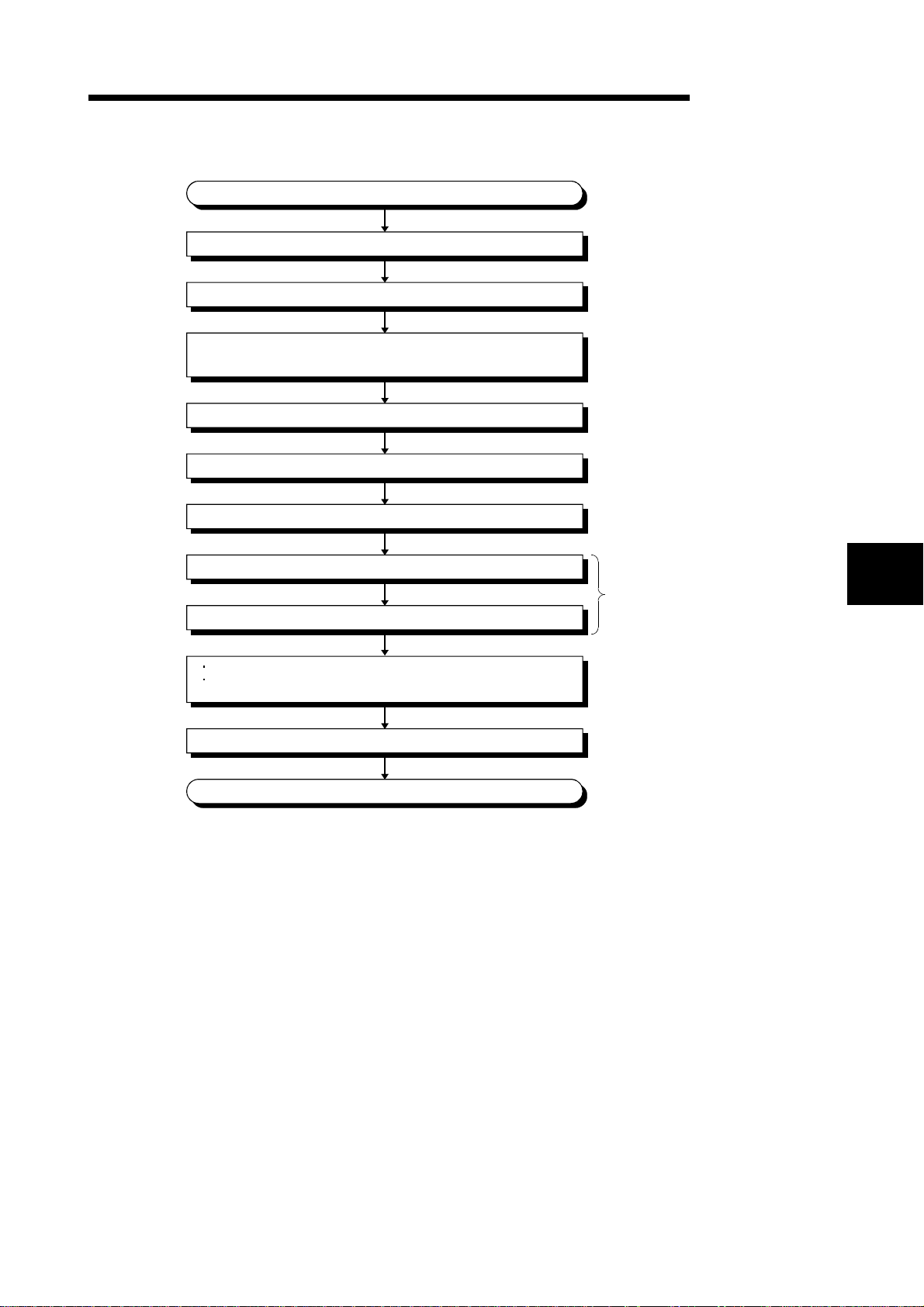
5 PRE-OPERATION SETTINGS AND PROCEDURE
(2) Procedure up to CC-Link data link
Start
Load the Master and Local modules to the base units.
Install the GOT to the control box.
Refer to the Master
⋅⋅⋅⋅⋅
module user's manual.
Refer to the user's manual
⋅⋅⋅⋅⋅
of the GOT used
MELSEC-GOT
Check that the Master and Local modules operate independently.
(Hardware test)
Connect the remote modules and GOT with CC-Link dedicated cable.
Set the station number switches of the A8GT-J61BT15.
Switch on the GOT, remote modules and Master module in this order.
Confirm the connection status of each module. (Line test)
Write a parameter setting program.
Write a communication program for monitoring by Cyclic transmission.
When performing monitoring in the dedicated command monitor method,
create a sequence program that will execute the dedicated commands.
Start data link and monitor data on the GOT.
Complete
Refer to the Maste module
⋅⋅⋅⋅⋅
user's manual.
Refer to Section 5.5
⋅⋅⋅⋅⋅
Refer to Section 5.2
⋅⋅⋅⋅⋅
Refer to the Maste module
user's manual.
5
5 - 2 5 - 2
Page 51

5 PRE-OPERATION SETTINGS AND PROCEDURE
5.2 Names of the Parts and Their Setting s
This section provides the names of the A8GT-J61BT15 parts and how to set the
switches.
6) 8) 6)
MELSEC-GOT
5)
4)
ON
3)
1)
2)
21
3
2
5
0
7
8
3
2
5
0
7
8
3
2
5
0
7
8
MODE
OCCUPY STATION
10
1
BAUDRATE
L RUN
SD
RD
L ERR.
STATION NO.
CAUTION
Do not mount nor dismount
a module while the power
is supplied.
MITSUBISHI
DATALINK UNIT
MODEL
A8GT-J61BT15
DATE
MITSUBISHI ELECTRIC CORPORATION
MADE IN JAPAN BD992C000H58
1357
7)
Number Name Description
Station number setting
switches
1)
3
2
4
1
5
0
6
9
7
8
3
2
4
1
5
0
6
9
7
8
Used to set the station number of the A8GT-J61BT15 between 1 and 64. (Factory setting: 01)
Use "
10" to set the tens.
Use "
1" to set the units.
DA
DG NC NC
2468
DB SLD (FG1) NC
6)7)
Used to set the transmission speed of the module. (Factory setting:0)
Number to be Set Transmission Baudrate
Transmission baudrate
setting switch
2)
3
2
4
1
5
0
6
9
7
8
0 156kbps
1 625kbps
2 2.5Mbps
3 5Mbps
4 10Mbps
5 to 9
Reserved (If the value you set is 5 to 9, the L.ERR
LED is lit to indicate a communication error.)
5 - 3 5 - 3
Page 52
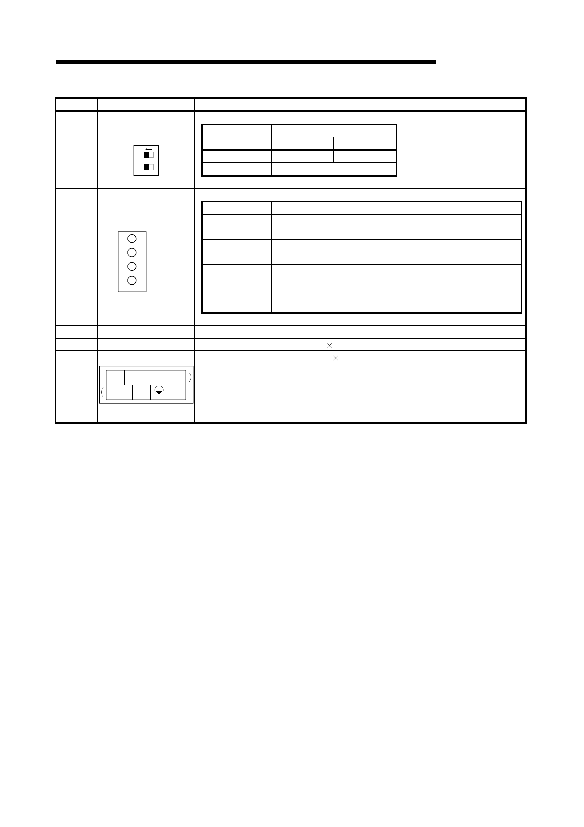
5 PRE-OPERATION SETTINGS AND PROCEDURE
Number Name Description
Number of stations
occupied setting switch
3)
21ON
Indicator LEDs
L RUN
4)
SD
RD
L ERR.
5) Connector Connector for connection to the GOT
6) M odule fixing screws Screws for installation to the GOT (M3 3 screw)
Terminal block
1357
DA
7)
DG NC NC
2468
DB SLD (FG1) NC
Used to set the number of occupied stations. (Factory setting:OFF(4 stations) )
Number
Switch Position
ON OFF
SW1 1 stations 4 stations
SW2 Must not be used
Data link status can be conformed by the on/off statuses of the LEDs.
LED Name Description
L RUN LED
On:Indicates that communication is normal.
Off:Indicates a communication br e a k ( time excess err o r ) .
SD LED On:Indicates data transmission.
RD LED On:Indicates data receive.
On: Indicates a communication data error (CRC error).
L ERR.
LED
Flicker: Indicates that any switch (1 to 3) position was changed while
power is on.
Off: Indicates that co mmun i ca tio n is normal.
Terminal block for cable connection (M3 8 screw)
MELSEC-GOT
8) Rating plate ———
5 - 4 5 - 4
Page 53

5 PRE-OPERATION SETTINGS AND PROCEDURE
5.3 Handling Instructions
Tighten the mounting and terminal screws of the A8GT-J61BT13 within the following
ranges.
Screw Location Tightening Torque Range
Module mounting screw (M3 screw) 39 to 59N•cm
Terminal block terminal screw (M3 screw) 39 to 59N•cm
Terminal block mounting screw (M3.5 screw ) 59 to 88N•cm
MELSEC-GOT
5 - 5 5 - 5
Page 54

5 PRE-OPERATION SETTINGS AND PROCEDURE
5.4 Mounting Procedures
This section provides the procedures to mount the A8GT-J61BT15 to and from the GOT.
(1) Mounting the A8GT-J61BT15 to the GOT-A900 Series
1) Fit the communication module securing fixtures in
the GOT main unit.
2) Mount the A8GT-J61BT15 on the GOT interface.
3) Tighten and fix the mounting screws (3 pcs.) of the
communication module in the specified torque
range. (39 to 59 N•cm)
4) To remove the unit, reverse the installation
procedure.
MELSEC-GOT
(2) Mounting the A8GT-J61BT15 to the GOT800 Series
1) Fit the A8GT-J61BT15 to the mounting section of
the GOT.
2) Tighten the module fixing screws (3 pcs.) to within
the specified torque range (39 to 59N•cm).
3) To remove the unit, reverse the installation
procedure.
5 - 6 5 - 6
Page 55
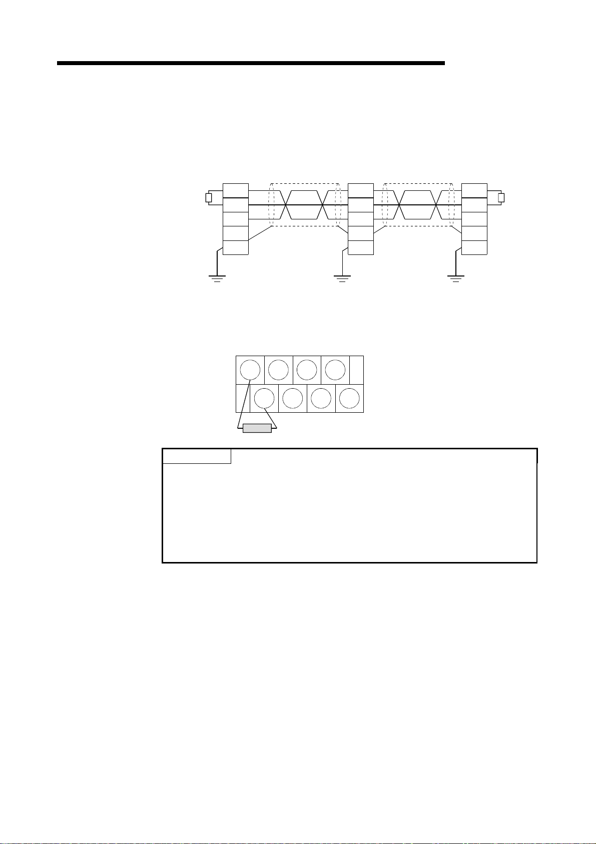
5 PRE-OPERATION SETTINGS AND PROCEDURE
T
r
5.5 Wiring Method
The following diagram shows how to wire the GOT and CC-Link system modules.
(1) Wiring the GOT and CC-Link system modules by CC-Link dedicated cable
Master module GOT I/O module, etc.
erminal
esistor
(2) Connection of terminal resistor to the GOT
When connecting a terminal resistor to the GOT, always connect it in the following
position.
The terminal resistor is contained in the package of the Master module.
DA
DB
DG
SLD
FG
(Blue)
(Yellow)
(White)
CC-Link dedicated cable
DA
DB
DG
CC-Link dedicated cable
SLD
FG1
MELSEC-GOT
DA
DB
DG
SLD
FG
Terminal
resistor
DA DG NC NC
DB SLD FG1 NC
Terminal resistor
POINT
• The "terminal resistors" supplied with the Master module must be connected to
the modules at both ends of data link. (Connect them across DA-DB.)
• Connect the shield wire of the CC-Link dedicated cable to "SLD" of each module.
Since "SLD" is connected to "FG/FG1" internally, always ground the FG terminal
and FG1 terminal to the protective ground conductor.
• The FG terminal of the GOT power supply and the FG1 terminal of the A8GTJ61BT15 must be connected separately.
5 - 7 5 - 7
Page 56

6 PROGRAMMING
MELSEC-GOT
6. PROGRAMMING
6.1 Sequence Program Example When Monitoring Using the Normal M onitor Method
The following system example is used to describe the sequence program in this
section. Refer to the CC-Link Master Module User's Manual regarding the sequence
program for the entire CC-Link system.
6.1.1 System configuration of the prog r am example
Q2A
CPU
Master
unit
GOT
Station No. : 1 station
Number of
stations occupied : 2 station setting
6.1.2 Relationship among the PLC CPU , master station buffer memory, and remote devi c e stations
GOT
(Remote device starion)
Remote input (RX)
RX00 to RX0F
RX10 to RX1F
RX20 to RX2F
RX30 to RX3F
Remote output (RY)
RY00 to RY0F
RY10 to RY1F
RY20 to RY2F
RY30 to RY3F
Remote register (RWw)
(Write area)
RWw0
RWw1
RWw2
RWw3
RWw4
RWw5
RWw6
RWw7
Remote register (RWr)
(Read area)
RWr0
RWr1
RWr2
RWr3
RWr4
RWr5
RWr6
RWr7
M0 to M15
M16 to M31
M32 to M47
M48 to M63
M100 to M115
M116 to M131
M132 to M147
M148 to M163
D100
D101
D102
D103
D104
D105
D106
D107
D200
D201
D202
D203
D204
D205
D206
D207
Address
E0
E1
E2
E3
Address
160
161
162
163
Address
1E0
1E1
1E2
1E3
1E4
1E5
1E6
1E7
Address
2E0
2E1
2E2
2E3
2E4
2E5
2E6
2E7
Master station PLC CPU
Remote input (RX)
H
RX00 to RX0F
H
RX10 to RX1F
H
RX20 to RX2F
RX30 to RX3F
H
Remote output (RY)
RY00 to RY0F
H
H
RY10 to RY1F
RY20 to RY2F
H
H
RY30 to RY3F
Remote register (RWw)
(Write area)
H
H
H
H
H
H
H
H
H
H
H
H
H
H
H
H
RWw0
RWw1
RWw2
RWw3
RWw4
RWw5
RWw6
RWw7
Remote register (RWr)
(Read area)
RWr0
RWr1
RWr2
RWr3
RWr4
RWr5
RWr6
RWr7
6
6 - 1 6 - 1
Page 57
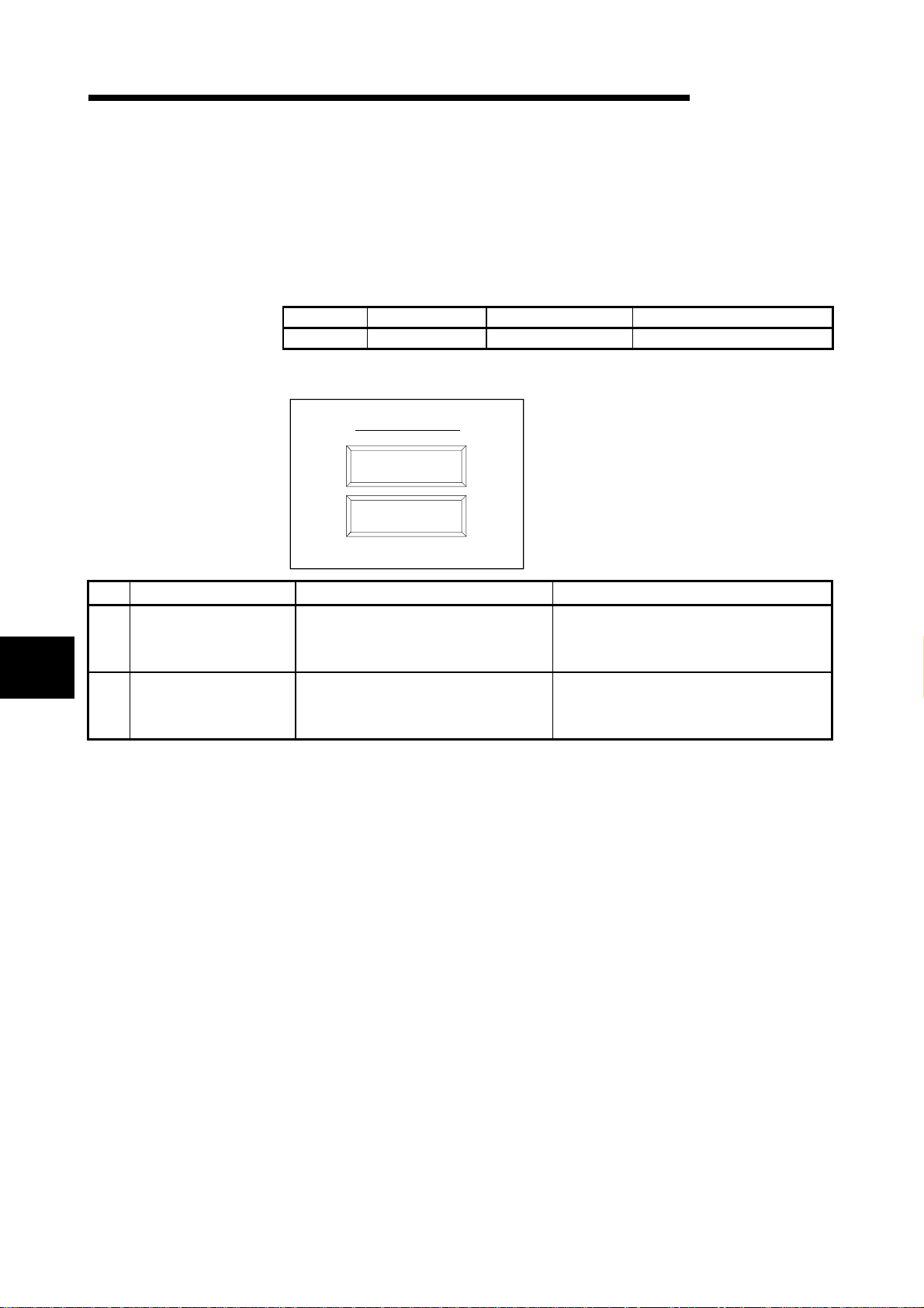
6 PROGRAMMING
6.1.3 Examples of created monitor screen data
The following are the monitor screen data examples of the A970GOT + A8GTJ61BT15 (remote device station).
Refer to the help function of GT Designer for the way to set each object function.
(1) Common setting
Setting Item PLC Type GOT Type Base Screen Switching Device
Settings MELSEC-QnA,Q A97*GOT/GT SoftGOT Ww0
(2) Base screen No. 1 settings
To main menu
MELSEC-GOT
6
To operating
command screen
To production
situation screen
No. Object Function to Be Set Setting Operation
Bit SET: X1 (RX1) to M1
1) Touch key function
2) Touch key function
Bit RST: X0 (RX0) to M0
Bit RST: X2 (RX2) to M2
Bit SET: X2 (RX2) to M2
Bit RST: X0 (RX0) to M0
Bit RST: X1 (RX1) to M1
1)
2)
Settings made to switch to base screen No. 2.
Settings made to switch to base screen No. 3.
6 - 2 6 - 2
Page 58

6 PROGRAMMING
MELSEC-GOT
(3) Base screen No. 2 settings
Operating command screen
Parts
Line1
Line2
Line3
1)
2)
3)
Production
situation
Main
screen
7)
8)
1
Start-up2Start-up3Start-up
5)
4)
6)
No. Object Function to Be Set Setting Operation
1) Numerical input function Write device Wr0 to D200
2) Numerical input function Write device Wr1 to D201
3) Numerical input function Write device Wr2 to D202
4) Touch key function Bit alternate: X3 (RX3) to M3
5) Touch key function Bit alternate: X4 (RX4) to M4
6) Touch key function Bit alternate: X5 (RX5) to M5
Settings made to store the values entered with the
numerical input function into D200-D202.
Settings made to store the ON/OFF information
entered with the touch key function into M200M201.
Bit SET: X2 (RX2) to M2
7) Touch key function
Bit RST: X0 (RX0) to M0
Settings made to switch to base screen No. 3.
Bit RST: X1 (RX1) to M1
Bit SET: X0 (RX0) to M0
8) Touch key function
Bit RST: X1 (RX1) to M1
Settings made to switch to base screen No. 1.
Bit RST: X2 (RX2) to M2
(4) Base screen No. 3 settings
Production situation screen
Parts A
Line1
Line2
Line3
Line1
Line2
start-up
start-up
7) 8)
No. Object Function to Be Set Setting Operation
1) Numerical display function Monitor device: Ww1 (RWw1) from D101
2) Numerical display function Monitor device: Ww2 (RWw2) from D102
3) Numerical display function Monitor device: Ww3 (RWw3) from D103
4) Touch key function Monitor device: Ww4 (RWw4) from D104
5) Touch key function Monitor device: Ww5 (RWw5) from D105
6) Touch key function Monitor device: Ww6 (RWw6) from D106
7) Lamp display function Monitor device: Y0 (RY0) from M100
8) Lamp display function Monitor device: Y1 (RY1) from M101
9) Lamp display function Monitor device: Y2 (RY2) from M102
Bit SET: X1 (RX1) to M1
10) Touch key function
Bit RST: X0 (RX0) to M0
Bit RST: X2 (RX2) to M2
Bit SET: X0 (RX0) to M0
11) Touch key function
Bit RST: X1 (RX1) to M1
Bit RST: X2 (RX2) to M2
Parts B
1)
3)
5)
Line3
start-up
2)
4)
6)
Production
situation
9) 10) 11)
Main
screen
Settings made to display the values stored in
D101-D106.
Settings made to display on the GOT the line
operating statuses (ON/OFF) output to the remote
I/O station.
Settings made to switch to base screen No. 2.
Settings made to switch to base screen No. 1.
6 - 3 6 - 3
Page 59

6 PROGRAMMING
MELSEC-GOT
(5) Sequence program exampl e
Refer to the Master Module User's Manual about the program for setting CC-Link
parameter.
Remote input(RX) read
Program for switching screen 1
Store the screen switching
infomation in the master station
Program for switching screen 2
Store the screen switching
infomation in the master station
Planned quantity read program
Program for switching screen 3
Store the screen switching
infomationin the master station
Store D200 to D202
in D103 to D105
Store the production quantity
and planned quantity
in the master station
Remote output (RY) wri te
6 - 4 6 - 4
Page 60

6 PROGRAMMING
MELSEC-GOT
6.2 Sequence Program Example When Monitoring Using Dedicated C ommand Moni tor Method
The following system example is used to describe the sequence program in this
section. Refer to the CC-Link Master Module User's Manual regarding the sequence
program for the entire CC-Link system.
6.2.1 System configuration of the prog r am example
QnA
CPU
Master
unit
GOT
Station No. : 1 station
Number of
stations occupied : 2 station setting
6.2.2 Relationship among the PLC CPU , master station buffer memory, and remote devi c e
stations
GOT
(Remote device starion)
Remote input (RX)
RX00 to RX0F
RX10 to RX1F
RX20 to RX2F
RX30 to RX3F
Remote output (RY)
RY00 to RY0F
RY10 to RY1F
RY20 to RY2F
RY30 to RY3F
Remote regist e r (R Ww )
(Write area)
RWw0
RWw1
RWw2
RWw3
RWw4
RWw5
RWw6
RWw7
Remote regist e r (R Wr )
(Read area)
RWr0
RWr1
RWr2
RWr3
RWr4
RWr5
RWr6
RWr7
M0 to M15
M16 to M31
M32 to M47
M48 to M63
M100 to M115
M116 to M131
M132 to M147
M148 to M163
D100
D101
D102
D103
D104
D105
D106
D107
D200
D201
D202
D203
D204
D205
D206
D207
Address
E0
E1
E2
E3
Address
160
161
162
163
Address
1E0
1E1
1E2
1E3
1E4
1E5
1E6
1E7
Address
2E0
2E1
2E2
2E3
2E4
2E5
2E6
2E7
Master station PLC CPU
Remote input (RX)
RX00 to RX0F
H
H
RX10 to RX1F
H
RX20 to RX2F
H
RX30 to RX3F
Remote output (RY)
H
RY00 to RY0F
H
RY10 to RY1F
RY20 to RY2F
H
RY30 to RY3F
H
Remote regist e r ( R Ww)
(Write area)
H
H
H
H
H
H
H
H
H
H
H
H
H
H
H
H
RWw0
RWw1
RWw2
RWw3
RWw4
RWw5
RWw6
RWw7
Remote regist e r (R Wr )
(Read area)
RWr0
RWr1
RWr2
RWr3
RWr4
RWr5
RWr6
RWr7
6 - 5 6 - 5
Page 61

6 PROGRAMMING
6.2.3 Examples of created monitor screen data
The following are the monitor screen data examples of the A970GOT+A8GT-J61BT15
(remote device station).
Refer to the help function of GT Designer for the way to set each object function.
(1) Common setting
Setting Item PLC Type GOT Type Base Screen Switching Device
Settings MELSEC-QnA,Q A97*GOT/GT SoftGOT GD100
(2) Base screen No. 1 settings
To main menu
MELSEC-GOT
To operating
command screen
To production
situation screen
No. Object Function to Be Set Setting Operation
1) Touch key function Base screen switching fixed value: 2 Setting made to switch to base screen No. 2.
2) Touch key function Base screen switching fixed value: 3 Setting made to switch to base screen No. 3.
1)
2)
6 - 6 6 - 6
Page 62
6 PROGRAMMING
(3) Base screen No. 3 settings
Operating command screen
Parts A
Line1
Line
2
Line
3
Motor start-up switch
Swich1 Swich2 Swich3 Swich4
Swich5 Swich6 Swich7 Swich8
Parts B
1)
2)
4)
3)
6)
5)
MELSEC-GOT
7)
1
start-up2start-up3start-up
8) 9)
10)
Production
situation
11)
Main
screen
12)
No. Object Function to Be Set Setting Operation
1) Numerical input function Monitor device: GD200
2) Numerical input function Monitor device: GD201
3) Numerical input function Monitor device: GD202
4) Numerical input function Monitor device: GD203
Settings made to store the values entered with the
numerical input function into GD200-GD205.
5) Numerical input function Monitor device: GD204
6) Numerical input function Monitor device: GD205
Switch 1: GD250 b0
Switch 2: GD250 b1
Touch key function
7)
(Switches 1 to 8)
Switch 3: GD250 b2
Switch 4: GD250 b3
Switch 5: GD250 b4
Switch 6: GD250 b5
Settings made to store the ON/OFF information
entered with the touch key function into the
specified bits (b0 to b7) of GD250.
Switch 7: GD250 b6
Switch 8: GD250 b7
8) Touch key function Bit alternate: GD255 b0
9) Touch key function Bit alternate: GD255 b1
10) Touch key function Bit alternate: GD255 b2
Settings made to store the ON/OFF information
entered with the touch key function into the specified
bits (b0 to b2) of GD255.
11) Touch key function Base screen switching fixed value: 3 Setting made to switch to base screen No. 3.
12) Touch key function Base screen switching fixed value: 1 Setting made to switch to base screen No. 1.
(4) Base screen No. 3 settings
Production situation screen
Parts A
Line
1
Line
2
Line
3
No. Object Function to Be Set Setting Operation
1) Numerical display function Monitor device: GD101
2) Numerical display function Monitor device: GD102
3) Numerical display function Monitor device: GD103
4) Numerical display function Monitor device: GD104
5) Numerical display function Monitor device: GD105
6) Numerical display function Monitor device: GD106
7) Touch key function Base screen switching fixed value: 2 Setting made to switch to base screen No. 2.
8) Touch key function Base screen switching fixed value: 1 Setting made to switch to base screen No. 1.
6 - 7 6 - 7
1)
3)
5)
Operating
command
7)
Parts B
2)
4)
6)
Main
screen
8)
Settings made to display the values stored in
GD101-GD106.
Page 63

6 PROGRAMMING
MELSEC-GOT
(5) Sequence program exampl e
Refer to the Master Module User's Manual about the program for setting CC-Link
parameter.
Remote input(RX) read
Execute only during power
supply is ON
Initial command data storage
Transfers master station
Initial processing request
flag ON
For executing next step
Continuous read command
data storage
Transfers master station
GOT request flag ON
Read the read data to
PLC CPU
For executing next step
Randam read data storage
Randam read data storage
Randam read data storage
Transfers master station
GOT request flag ON
For excuting next step
Read GD250 and 251 to
D400 and 401
For excuting next step
Continuous write data
storage
Transfers D500 to 505 to
D102 to 108
Transfers master station
GOT request flag ON
For executing next step
For executing continuous
read command
Remote output (RY) write
6 - 8 6 - 8
Page 64

7 TROUBLESHOOTING
7. TROUBLESHOOTING
This section gives simple troubleshooting for use of the A8GT-J61BT15.
POINT
By setting the alarm list display (system alarm) function to the display screen using
the graphics software, the GOT can quickly detect a link error, in addition to the
following errors.
When a link error occurs, the following error code and error messages are
displayed in the display field of the alarm list display (system alarm) function.
For more details on how to set up the alarm list display (system alarm) function and
the contents of display, refer to the manuals listed in the table below.
GOT-A900 Series GT Designer Help function
GOT800 Series
Error code Me ssage
402
• Communication disable (GOT800 Series)
• Communication time-out (GOT-A900 Series)
GOT Used Manuals to refer to
SW
NIW-A8GOTP Operati ng Ma nu al (Moni to r
Screen Creation Manual)
MELSEC-GOT
7.1 LED-Indicated Error Causes and Their C or rectiv e Acti ons
This section explains how to check errors indicated by the LEDs of the A8GTJ61BT15.
For errors related to the PLC CPU and Master module, refer to the user's manuals of
the PLC CPU and Master module.
(1) If the L RUN LED of the A8GT-J61BT15 goes off
Cause Corrective Action
CC-Link dedicated cable is broken or
shorted.
Master station stopped link. Check for an error at the Master station.
Station number was repeated.
GOT parameters have not been set.
Power is not supplied to the GOT or
voltage is insufficient.
Switch setting is outside the specified
range (station number 0 or 65 or more,
transmission speed 5 to 9).
Check and repair the CC-Link dedicated cable.
Switch power on again
number setting of the module of which station number
was repeated.
Correct the GOT parameter setting and switch power of
the GOT again
Supply power to the GOT and check the voltage of the
power supply.
Correct the switch setting and switch power on
1.
again
7
1 after correcting the station
1.
7 - 1 7 - 1
Page 65

7 TROUBLESHOOTING
7
(2) If the L ERR LED of the A8GT-J61BT15 flickers
Cause Corrective Action
Return the mode, station number or transmission
Mode, station number or transmission
speed switch setting was changed during
normal operation.
Station number or transmission speed
switch is faulty.
speed switch setting to the previous position and
switch power on again
If the L RUN LED is not lit after switching power on
again, the hardware may be faulty. Consult your
sales representative.
If the L ERR LED begins to flicker though switch setting
was not changed during operation, the hardware may
be faulty. Consult your sales representative.
(3) If the L ERR LED of the A8GT-J61BT15 is lit
Cause Corrective Action
Switch setting is outside the specified
range (station number 0 or 65 or more,
transmission speed 5 to 9).
Terminal resistors are left unconnected.
A8GT-J61BT15 or CC-Link dedicated
cable are affected by noise.
Correct the switch setting and switch power on
again
1.
Check that the terminal resistors are connected. If not,
connect them and switch power on again
• Connect both ends of the shield wire of the CC-Link
dedicated cable to ground (earth conductors
separately) via SLD and FG1 of each module.
• Securely connect the FG terminal of the module to
ground.
• Securely ground the piping when running cables in
piping.
1: Switch power on again: Switch power on again or turn on the reset switch.
MELSEC-GOT
1.
1.
7.2 Troubleshooting for Dedicated Command M oni tor
(1) If the error status flag turned on
Cause Corrective Action
Executed dedicated command is
incorrect.
Monitored device is outside the setting
range.
7 - 2 7 - 2
Check if the dedicated command is incorrect or not.
Check if the set device is outside the range or not.
Page 66

7 TROUBLESHOOTING
7.3 Communication Error Occurs betw een Master Stati on and GOT
If any repeated station number bit in any of the link special registers SW0098 to
SW009B (repeated station number status) switches on, check the GOT of the
corresponding station number in the following flowchart.
Troubleshooting flowchart used when the "ERR" LED of the Master station flickers
"ERR" LED of master station flickers
MELSEC-GOT
Parameter
setting match system
configuration?
Y
Any of Mast er
station link special registers
SW0080 to SW0083 (other
station data link status)
ON?
Y
Any of Master
station link special registers
SW0098 to SW009B (repeated
station number status)
ON?
Y
Check the module corresponding
to the bit switched on.
Station number switch
setting correct?
Y
Corresponding module faulty
N
Correct parameter setting
or system configuration.
N
Master station faulty
N
N
Correct station number switch setting.
Switch power on again
or turn on reset switch.
Check the module corresponding
to the bit switched on.
Power on?
Y
"POWER" LED lit?
Y
N
Switch power on.
N
Is supply voltage
within specified range?
Y
Master side check
GOT side check
N
within specified range.
Set supply voltage to
Corresponding module faulty
"RD" LED lit?
Y
To next page To next page To next page
N
Communication cable
wired correctly*1?
Y
Corresponding module faulty
N
Correct communication cable wiring.
7 - 3 7 - 3
Page 67
7 TROUBLESHOOTING
MELSEC-GOT
rom preceding pag e From preceding page
"L RUN" LED lit?
Y
"SD" LED lit (flicker)?
Y
N
"SD" LED lit (flicker)?
Y
N
Corresponding module faulty
Station number
switch setting correct
(not repeated)?
Y
N
Baudrate setting corre ct?
Y
Communication cable
wiring correct*1?
Y
Corresponding module faulty
(Baudrate switch)
N
Correct station number setting.
From preceding page
N
Correct baudrate setting.
Switch power on again
or turn on reset switch.
N
Correct communication cable wiring.
Switch power on again
or turn on reset switch.
Corresponding module faulty
(Station number switches)
Station number
switch setting correct
(not repeated)?
Y
Corresponding module faulty
(Station number switches)
N
Correct station number setting.
Switch power on again
or turn on reset switch.
Complete
*1: Check for short circuit, reverse connection, wire breakage, no terminal resistor, improper FG connection, improper overall
distance and improper interstation distance.
7 - 4 7 - 4
Page 68

APPENDICES
(
)
APPENDICES
Appendix 1. Outline Dimension Draw i ng
L RUN
SD
RD
ON
21
3
2
5
0
7
8
3
2
5
0
7
8
3
2
5
0
7
8
MODE
OCCUPY STATION
10
1
BAUDRATE
L ERR.
STATION NO.
CAUTION
Do not mount nor dismount
a module while the power
is supplied.
MITSUBISHI
DATALINK UNIT
MODEL
A8GT-J61BT15
DATE
MITSUBISHI ELECTRIC CORPORATION
MADE IN JAPAN BD992C000H58
1357
DA
DG NC NC
2468
DB SLD (FG1) NC
MELSEC-GOT
99(3.9)
34(1.34) 5
149(5.87)
0.2
Unit:mm(inch)
Appendix 2. Calculating Formulas of the Processing Time o f the Rem o te Device St a tion
When the A8GT-J61BT15 is Used
The following explains the calculating formulas of the processing time o f th e re mote
device station when the A8GT-J61BT15 is used (when the GOT is an remote device
station).
(1) Calculating formula
SM + LS 3 + 100 (processing time of the re mote device stat ion: 100 ms)
= processing time of the remote devi ce station when the A8GT-J61BT15 is
used
SM : Scan time of the Master station’s sequence program
LS : Link scan time
(2) Example of calculation
When SM: 10 ms, LS: 5 ms
10 + 5
3 + 100 = 125 (ms)
APP
APP - 1 APP - 1
Page 69

APPENDICES
MEMO
MELSEC-GOT
APP
APP - 2 APP - 2
Page 70

INDEX
Ind
[A]
Always write register command.................... 4-27
Always write request command.................... 4-27
[C]
Calculating formulas of the processing
time of the remote device station when
the A8GT-J61BT15 is used ........................App-1
Command list for the dedicated
command monitor method............................ 4-12
Communication error occurs
between master station and GOT................... 7-3
Compatible software version........................... 2-2
Continuous write command .......................... 4-20
Continuous read command........................... 4-16
[D]
Dedicated command monitor.......................... 4-1
Dedicated command monitor method ............ 6-5
Details of the I/O signals................................. 4-9
Difference between the A8GT-J61BT13
and the A8GT-J61BT15.................................. 1-1
[G]
GOTs which can use the A8GT-J61BT15...... 2-2
[H]
Handling instructions....................................... 5-5
[I]
Initial setting command ................................. 4-14
I/O signals transferred to/from
the master module........................................... 4-7
[L]
LED-indicated error causes and
their corrective actions .................................... 7-1
[N]
Names of the parts and their settings .............5-3
Normal monitor ...............................................4- 1
[O]
Outline dimension drawing .........................App-1
[P]
PLC CPU that allows monitoring.....................1-1
Pre-operation procedure..................................5-1
Programming....................................................6-1
[R]
Random read command................................4-18
Random write command................................4-22
Remote register assignment .........................4-11
[S]
Sequence Program Example When
Monitoring Using Dedicated Command
Monitor Method................................................6-5
Sequence Program Example When
Monitoring Using the Normal Monitor
Method .............................................................6-1
Setting of NW number .....................................4-6
Setting of PLC station number ........................4-6
Specifications...................................................3-1
General specifications..................................3-1
Performance specifications..........................3-1
System configuration.......................................2-1
Overall configuration....................................2-1
Instructions for system configuration...........2-2
[T]
Troubleshooting for Dedicated
Command Monitor ...........................................7-2
[W]
[M]
Monitor register command............................ 4-24
Monitor request command............................ 4-24
Monitor specification........................................ 4-1
Mounting procedures ...................................... 5-6
Index - 1 Index - 1
Wiring method..................................................5-7
Page 71

WARRANTY
Please confirm the following product warranty details before starting u se.
1. Gratis Warranty Term and Gratis Warranty Range
If any faults or defects (hereinafter "Failure") found to be the responsibility of Mitsubishi occurs during use of the product
within the gratis warranty term, the product shall be repaired at no cost via the deal er or Mitsubishi Service Company.
Note that if repairs are required at a site overseas, on a detached island or remote place, expenses to dispatch an
engineer shall be charged for.
[Gratis Warranty Term]
The gratis warranty term of the product shall be for one year after the date of purchase or del iv ery to a designat ed
place.
Note that after manufacture and shipment from Mitsubishi, the maximum distribution period shall be six (6) months, and
the longest gratis warranty term after manufacturing shall be eighteen (18) month s. T he gratis w arranty term of repair
parts shall not exceed the gratis warranty term before repairs.
[Gratis Warranty Range]
(1) The range shall be limited to normal use within the usage state, usa ge metho ds and u sage env ironment, etc.,
which follow the conditions and precautions, etc., giv en in the in struction manual, user's manual and caution labels
on the product.
(2) Even within the gratis warranty term, repairs shall be charged for in the follow ing cases.
1. Failure occurring from inappropriate storage or handling, carelessne ss or negl igence by the user. Failure c aused
by the user's hardware or software design.
2. Failure caused by unapproved modifications, etc., to the product by the user.
3. When the Mitsubishi product is assembled into a user' s device, Failure that could hav e been av oided if functions
or structures, judged as necessary in the legal safety measures th e user's dev ice i s subje ct to or as ne ces sary
by industry standards, had been provided.
4. Failure that could have been avoided if consumable parts (battery , backlight, fu se, etc.) de signate d in the
instruction manual had been correctly serviced or replaced.
5. Failure caused by external irresistible forces such as fires or abn ormal v oltages, a nd Failure c aused by force
majeure such as earthquakes, lightning, wind and water damage.
6. Failure caused by reasons unpredictable by scientific technology standards at time of shipment from M itsubishi.
7. Any other failure found not to be the responsibility of Mitsubishi or the user.
2. Onerous repair term after discontinuation o f producti on
(1) Mitsubishi shall accept onerous product repairs for sev en (7) y ears after production of t he product i s dis continu ed.
Discontinuation of production shall be notified w ith M itsubishi T echnical Bulletins, etc.
(2) Product supply (including repair parts) is not possible after productio n is di scontin ued.
3. Overseas service
Overseas, repairs shall be accepted by M itsubishi' s loc al ov erseas FA Center. N ote that the repair conditio ns at ea ch FA
Center may differ.
4. Exclusion of chance loss and secondary loss from warranty liability
Regardless of the gratis warranty term, Mitsubishi shall not be liable for compensation to damages caused by any cause
found not to be the responsibility of Mitsubishi, chance loss es, lo st profits in curred to the user by Failures of Mitsubishi
products, damages and secondary damages caused fro m spe cial rea sons regardless of Mitsubishi's expectations,
compensation for accidents, and compensation for damages to products other than Mitsubishi products and other duties.
5. Changes in product specifications
The specifications given in the catalogs, manual s or techni cal do cument s are subject to change without prior notice.
6. Product application
(1) In using the Mitsubishi MELSEC programmable logic controller, the usage conditions shall be that the application w ill
not lead to a major accident even if any problem or fault shoul d occur in the program mable lo gic c ontroller dev ice, and
that backup and fail-safe functions are systematical ly prov ided outside of the dev ice for any proble m or fault.
(2) The Mitsubishi general-purpose programmable logic controll er has been design ed and ma nufactured for a pplications
in general industries, etc. Thus, applications in which the public could be affected such as in nucle ar power plants and
other power plants operated by respective power companies, and applic ations i n which a special quality assurance
system is required, such as for Railway companies or N ational Defen se purpose s sha ll be excluded from the
programmable logic controller applications.
Note that even with these applications, if the user approves that the application is to be limited and a special qua lity is
not required, application shall be possible.
When considering use in aircraft, medical appli cation s, railw ay s, incineration and fuel dev ices, manned transport
devices, equipment for recreation and amusement, and safety dev ices, i n which human life or assets could be greatly
affected and for which a particularly high reliability is required in term s of safety and c ontrol sy stem, p lease consult
with Mitsubishi and discuss the requ ired spe cificati ons.
Page 72

A8GT-J61BT15 Type CC-Link Communication Module
User,s Manual
MODEL
MODEL
CODE
A8GT-J61BT15-U-E
1DM074
IB(NA)-66788-C(0406)MEE
HEAD OFFICE : 1-8-12, OFFICE TOWER Z 14F HARUMI CHUO-KU 104-6212,JAPAN
NAGOYA WORKS : 1-14 , YADA-MINAMI 5-CHOME , HIGASHI-KU, NAGOYA , JAPAN
When exported from Japan, this manual does not require application to the
Ministry of Economy, Trade and Industry for service transaction permission.
Specifications subject to change without notice.
 Loading...