

Page 1

Page 2
...
i
0
Precautions Regarding Safety
0
When using your product, please make sure that you have read this manual, as
well
as any related manuals
introduced in this manual, and that careful attention is paid to safety and
correct
handling of the equipment.
Only safety precautions which apply to this specific product have
been
noted here. For precautions pertain-
ing to the PC system, please refer to the User’s Manual provided with the CPU unit.
Safety precautions noted in this section are distinguished by
either
a “Danger” or a “Caution” mark, depend-
ing on the degree of danger involved.
I
Erroneous handling could result in hazardous conditions and could
I
I
I
I
I
I
(BCAUTION?
cause minor or moderately serious injury,
or
could result in dam-
I
age
to
physical property.
Items marked with
ACAUTION
could also cause significant damage or injury, depending on the
circumstances. Precautions marked by either of these signs should be carefully observed and the
contents considered particularly important.
This manual should be stored carefully in a place where
it
is easily accessible when necessary, and
should always
be
passed on to the end user
if
the equipment is transferred to another user.
[Precautions Regarding Design]
@DANGER
~ ~ ~ ~ ~ ~~~~~~~~~~~~~
0 A safety circuit should
be
installed on the exterior of the PC to ensure safe operation of the entire
system even if there is a problem with the external power supply, or if the PC main unit breaks
down.
Erroneous output or operation can result in accidents.
(1)
The circuit configuration on the exterior of the PC should include interlock circuits such
as
an
emergency stop circuit, upper and lower limit position detectors, and other circuits to protect
the machinery from damage.
(2)
A
breakdown in an output unit relay, transistor, or other component could possibly cause the
output to remain on
or
off
inappropriately. The circuit configuration should allow external
monitoring of output signals where serious accidents could possibly occur.
[Precautions When Disposing
of
the Equipment]
/9
CAUTION
0
When disposing of this product,
it
shouM
be
handled through industrial product disposal channels.
Page 3
Page 4
Introduction
,.
.;:
I>
.,
1.
Thank
you
for
purchasing
the MitsubW
tMEtSEC-A
Series
General-Purpose PC.
Before using your product, please
WZhF
manual carefully and ,make..sure.
you';wst@4b
functions
ar@
performance of the A Series sequencer, and that you use it carefulv and prrectly.
'
should the product be transferred to another user, please make sure this manual
is
passed along to the end user
together with the equipment.
.
.-
. .
,
...
.
.
.
.
--.
~
.
..
-
I.
.
.-
-I
1. Overview 1-1
2.
System Configuration
2-1
-2-5
2.1 Overall Configuration
.
..
. , ..
,.
. .
..
. ..
. , .. .. . . . ..
...
.
.
.. ..
.
,
.. ..
.
,
.
..
.
, . ,
...
..
, ,
.. . .. .. .. .. .. .. .. . , .. .. . , .
..
..
. , .
..
..
. , .. .
..
..
...
, . , ,
...
2-1
2.1.1 When Used with a Building-Block CPU
....................
I.....I.....I.....I......I....I.I.....I
,...,.,.,....,
2-1
2.1 .2 When Used with a Compact CPU
.,............,
................................
,.....,
....,.,......,
,....,
,.....,.
2-2
2.1.3 When Used with a Small Building-Block CPU
..........................................
,......
......,.....,
,
2-3
2.2 Applicable Systems
.
. .. .. . . . . . . . , .
. . . . . . . . . , . , .
. . . .
.
,
. . . . . . , . . . . . . , . , . , . , . . . . , . , . . . . .
, ,
. . .
.
, ,
. . . . . . . . . .
. , . . . .
. . . . . . . . .
,
.
. . . . . . . . . . . . . .
.
2-4
2.3 Precautions Concerning the System Configuration
....................................................................
2-5
2.3.1 Precautions Concerning the External Power Supply
.I.....I............I....I.I..........I......I.......I
2-5
2.3.2 Correcting Individual Error in the Linear Scale
...........
.................................
,....,
,.....,......
2-5
C:
+
3. Specifications 3-1 -3-1
0
3.1 General Specifications
.....
.
..
..
. , . . . ..
. .
..
. .. . .
.. ..
.
,
. .. .. . . .. . ..
, ,
.. .. . , . , . .. . , .
..
..
.
,
.. ..
.
,
.. ..
.
.
..
.
,
.
.
,
..
.. . . .
.. . ..
,
.
.. . ..
,
.
.. .. .
.
3-1
3.2 Performance Specifications
,
.
. . . . .
. . . . , .
,
.
. . . . . , . , . . . . , . , .
, . ,
. . . . , .
. . . . . . , .
. . . .
.
. .
. . . . . . . . . . . . . . . . . , . . . . . . . . . . . .
. . . .
. . . . . . . . . . . . . .
.3-2
3.3 Signals Input to and Output from the PC CPU
,............I.I............I.........I......I.............I......I.....,..
3-3
3.3.1 Table of Input and Output Signals
....................
.......
..............,....
,............,
......................
3-3
3.3.2 Functions of Input and Output Signals
...I............I....I..............I.....I......I....I.II....II.....,....
3-4
3.4.1 Buffer Memory Allocation
. .. . , . . . . . . . . . . .
.
, . ,
. . .
.
, , ,
, . ,
, . , . , , ,
, . , , . , . ,
. . , .
, , . ,
.
. , .
, , . ,
. . , . , . . , . , . . , . . . . . . . . . , . . . . . . . . . .
.3-6
3.4.2 An Explanation of the Storage Area
,...,.,
,.....,
......
.................................
..........................
3-7
3.4 Buffer Memory
I....I.I...I.....I.......I.......I....I...................I......I.....,.....,,....,,............,......,............,.....
3-6
r-
-
4. Settinas and Procedures Prior to Omration 4-1 -4-5
,
.'
-1
-
Page 5
4
.4
..
6. Troubleshootinn 6-1
-6-3
Appendices
A-I -A-8
Appendix 1 I Supersonic Linear Scale BTL Specifications
...II......I.I...II......I......I......I..................I..........
A-1
1.1 Supersonic Linear Scale
BTL
Specifications
...,...
.. . , ...
.. . , .
...
.. , .
..,..
..
.....
.. .
..
.. . , .....
..
...... , ...
..
A-1
1.2 Supersonic Linear Scale
BTL
External Dimensions
I......I.......I......I.....II.............I......I.....
A-2
1.3 Orders and Consultation
.I......I......I.......I......I......I.I...II.I....I....I.II...I.I....,.,,.....,,.............,
A-6
Appendix 2. External Dimensions
........................................................................................................
A-8
2.1 A64BTL Supersonic Linear Scale Interface Unit
............................................................
A-8
Page 6

Page 7

\
Page 8
A
2.
System,Configuration
MELSEGA
2.1
Overall
Configuration
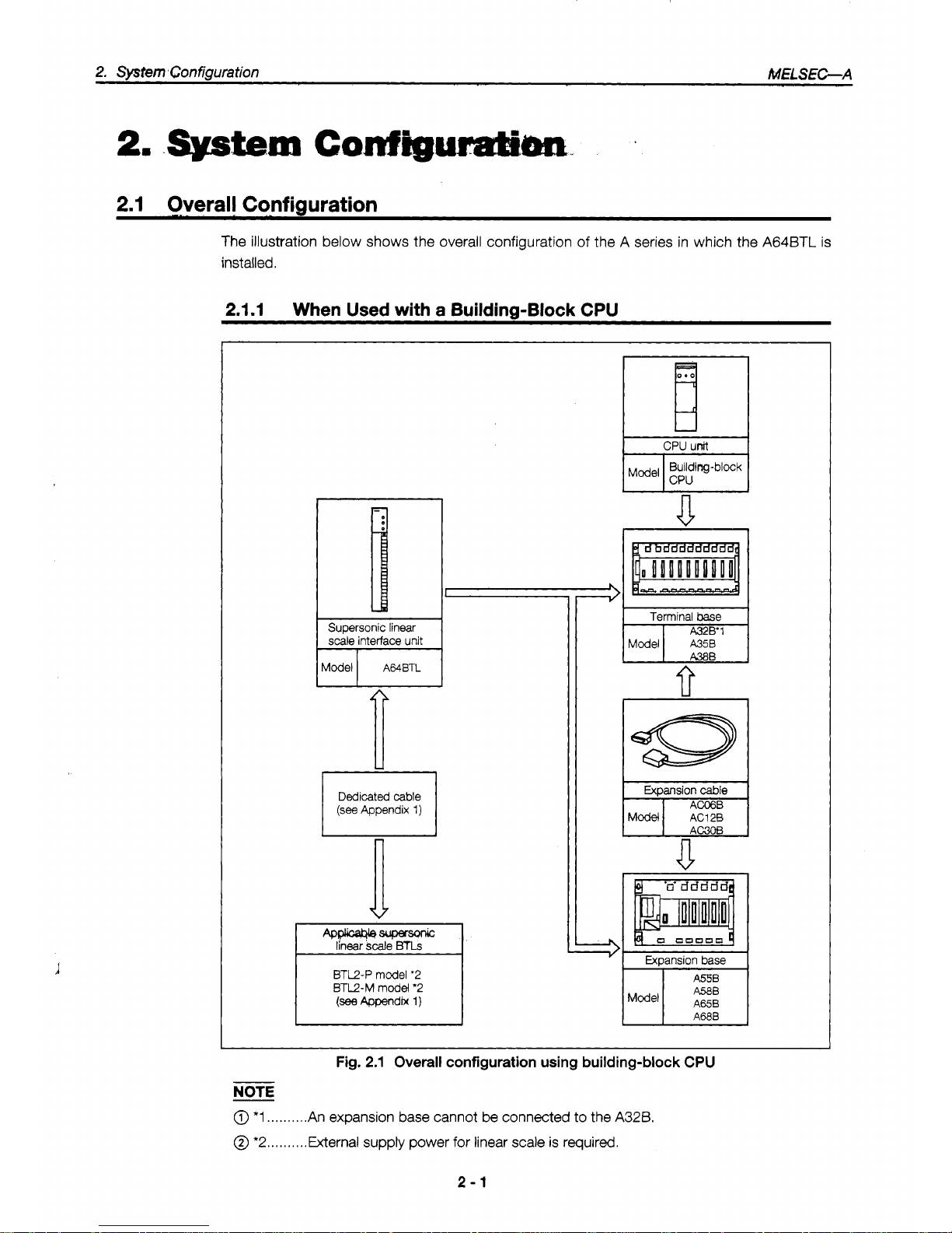
The illustration below shows the overall configuration of the A series in which the A64BTL is
installed.
2.1.1
When Used with
a
Building-Block CPU
CPU
unit
Terminal
base
fi
A380
FTGFl
Expansion
cable
A4wa4bsuper-
linear
scale
BTLs
BTL2-P model
'2
BTL2-M model
'2
I
Fig.
2.1
Overall
configuration
using
building-block CPU
NOTE
@
*1
..,.......
An expansion base cannot
be
connected
to
the
A32B.
@
*2..
. . . . .
.
..External supply power for linear scale
is
required.
2-1
Page 9
2,
SysmConfiguration
-
,_
MELS-A
Supersonic
linear
scale interface unit
Dedicated
cable
(see
Appendix 1)
a
BTU-P model
'1
BTL2-M model
'1
(see
Appendix
1)
ipJ-
Expansion base
I
bl
AOJZClOB
I
AOJ2C04B
AOJ2COl
t
I10 unit
I
I
Model I AOJ2
I/O
unit
I
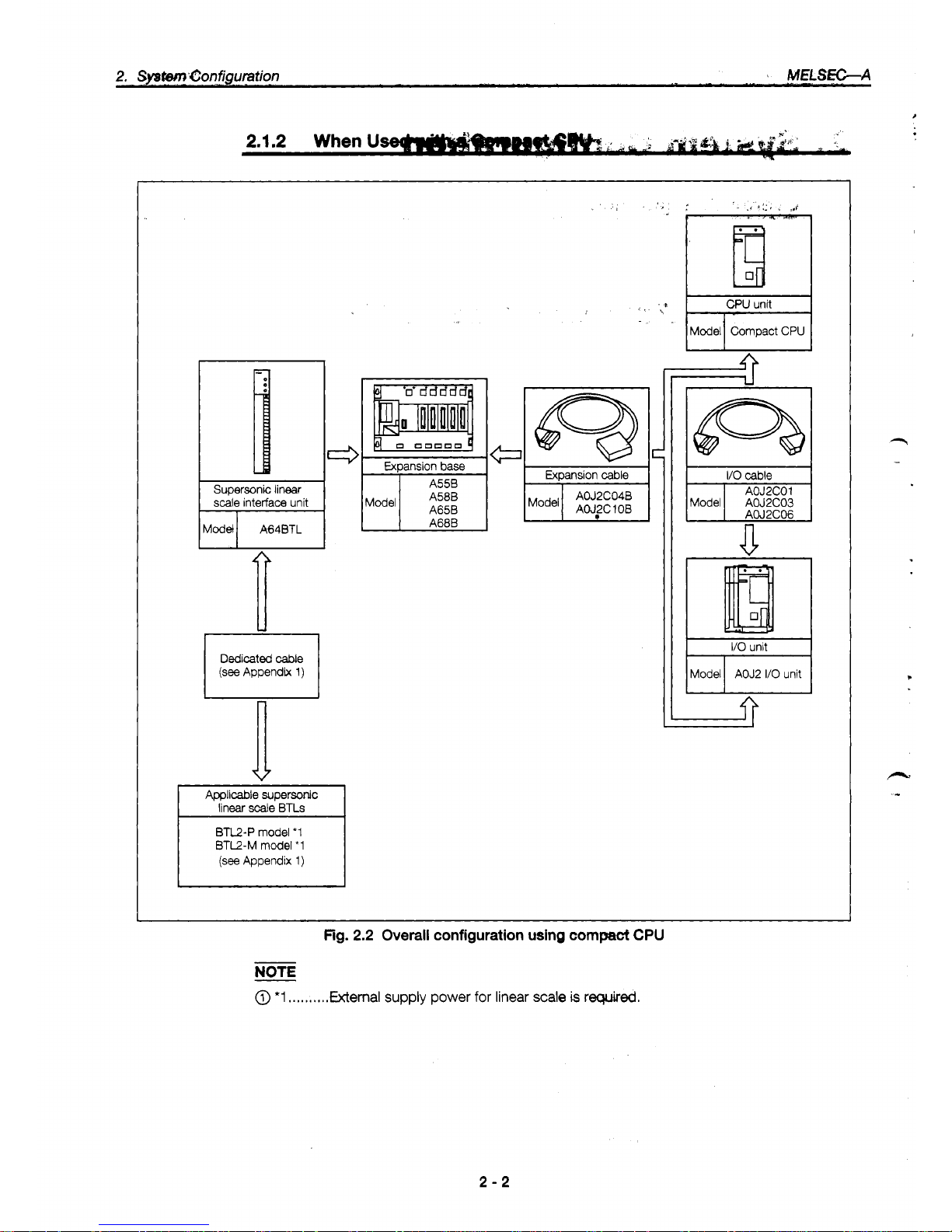
Fig.
2.2
Overall
configuration
using
compact
CPU
NOTE
@
*1
.....,,.,.
External supply power
for
linear
scale
is
required.
2-2
Page 10
2.1.3
When
Used
with
a
Small
BuAilding-6h&
CPU
I
Supersonic linear scale
interface unit
Model
A64BTL
Applicable supersonic
linear
Scale
BTLs
BTL2-P model
'1
BTL2-M
model
'1
(see
Appendix
1)
L
A55B
(Sl)
A58B
(Sl)
A68B
61)
Small
building-block
type
Expansion cable
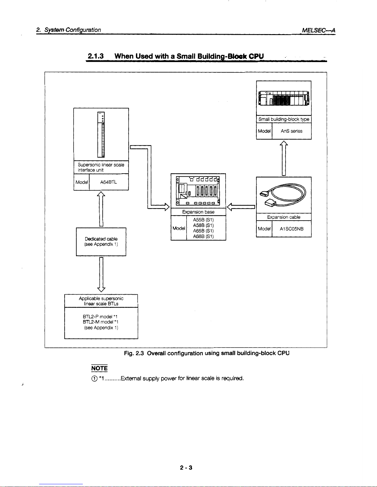
Fig.
2.3
Overall configuration using
small
building-block
CPU
NOTE
@
*1
,,,.,.,,,.External
supply
power
for
tinear
scale
is
required.
2-3
Page 11
2.2
Applicable
@#a~eaa~
.k
t,~~~~~,Jk,
!~~~;~i
!
,,;..'
il;.;,
.'.
?.*e
,-'.
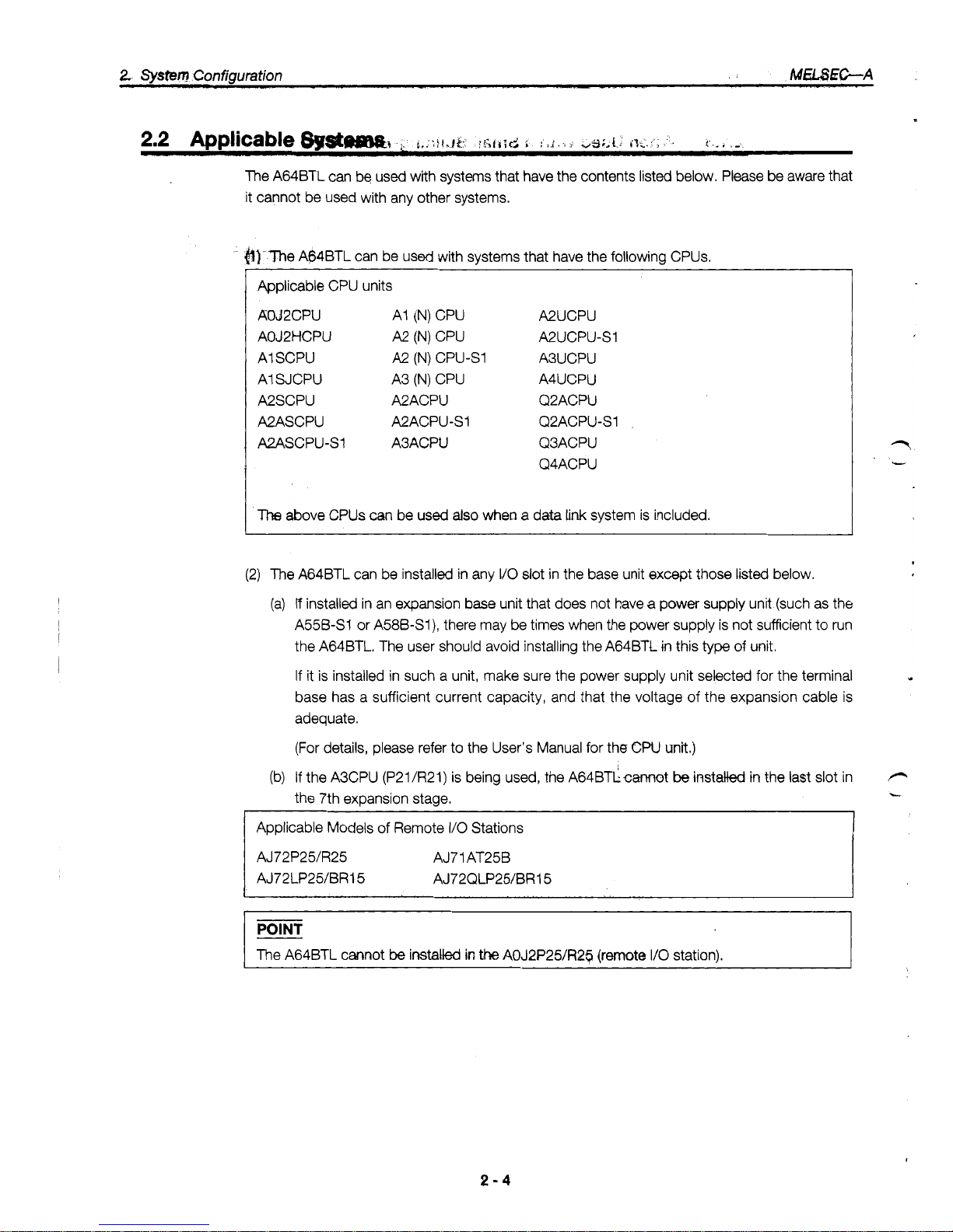
The A64BTL can be used with systems that have the contents listed below, Please be aware that
it cannot be used with any other systems.
&)-The
A64BTL can be used with systems that have the following CPUs.
Applicable CPU units
AOJ2CPU
AI
(N)
CPU
A2UCPU
AOJ2HCPU
A2
(N)
CPU
A2UCPU-s1
AI SCPU
A2
(N)
CPU-S1
A3UCPU
AI SJCPU
A3
(N)
CPU
A4UCPU
A2SCPU A2ACPU
Q2ACPU
A2ASCPU A2ACPU-S1
Q2ACPU-S1
A2ASCPU-SI A3ACPU
Q3ACPU
Q4ACPU
The
above CPUs
can
be used
also
when a data
link
system is included.
(2) The A64BTL can be installed in any
I/O
slot
in the base unit except those listed below.
(a)
If
installed in an expansion base unit that does not have a power supply unit (such as the
A55B-S1 or A58B-S1), there may be times when the power supply is not sufficient to run
the A64BTL. The user should avoid installing the A64BTl in this
type
of
unit.
If
it is installed in such a unit, make sure the power supply unit selected for the terminal
base has a sufficient current capacity, and that the voltage
of
the expansion cable is
adequate.
Y
(For details, please refer to the User's Manual for the
CW
unit.)
(b)
If the A3CPU (P21/R21) is being used, the A64BTLcmot
be
installed
in
the last slot in
P
the 7th expansion stage.
-
Applicable Models of Remote
I/O
Stations
AJ72P25/R25 AJ71AT25B
AJ72LP2UBRl 5 AJ72QLP2WBR15
I
The A64BTL cannot
be
installed
in
the
AOJ2P25/R2$ (remote
110
station).
2-4
Page 12
2.
System
Configuration
-&A
2.3
Precautions Concerning the System Configuration
2.3.1 Precautions Concerning the External Power SUDD~Y
In
order to use the
A64BTL,
an external
24
VDC
power supply is required.
2.3.2 Correcting Individual Error in the Linear Scale
Each linear scale has the correction value for the actual supersonic
speed
stamped on the scale.
Positional measurement can be carried out more accurately if this numeric value is entered in the
buffer memory.
(For
detailed information, please
see
section
3.4.2
(4),
“An Explanation
of
the Storage Area in the
Buffer Memory”.)
2-5
Page 13

c
.
,/
Page 14
3.
SpecifiIcetions
hELSK;-A
3.
Specifications
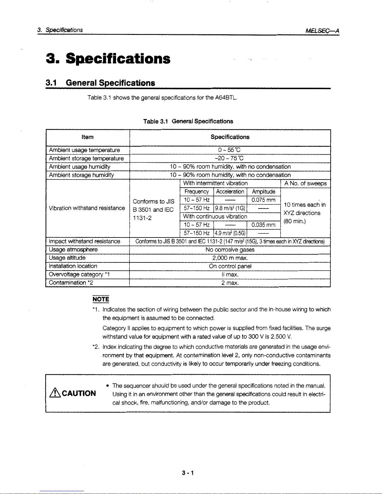
Table 3.1 shows the general specifications for the A64BTL.
Item
Table
3.1
General Specifications
Specifications
0
-
55°C
I
-20 - 75
"C
10
-
90%
room humidity, with no condensation
I
Ambient storage humiditv
I
Vibration withstand resistance
Impact
withstand
resistance
10
-
90%
room humidity, with
IX)
condensation
With intermittent vibration
Frequency
I
Acceleration I Amplitude
A
No.
of sweeps
Conforms to
JIS
0.075
mm
B
3501
and
IEC
1131-2
10
-
57 HZ
0.035
mm
I
I
57-1
50
Hz 14.9
m/s2
(0.5G)
I
-
Confm
to
JIS
B
3501
and
IEC
1
131
-2
(1
47
rrJs2
(1
5G),
3
times
ea&
in
x/z
directions)
Usage atmmere
Usage altitude
Installation location
Overvoltage category
*1
No
corrosive gases
I
~~
2,000
m max.
On control Dane1
I1
max.
I
I
Contamination *2
NOTE
2
max.
I
*I.
Indicates the section of wiring between the public sector and the in-house wiring to which
the equipment is assumed
to
be connected.
Category
II
applies to equipment to which power is supplied from fixed facilities.
The
surge
withstand value for equipment with a rated value of up to
300
V
is
2,500
V.
*2. Index indicating the degree to which conductive materials are generated in the usage envi-
ronment by that equipment. At contamination level
2,
only non-conductive contaminants
are generated, but conductivity is likely to occur temporarily under freezing conditions.
The
sequencer should be used under the general Specifications noted in the manual.
A
CAUTION
Using it in an environment other than the general specifcations could result in electrical shock, fire, malfunctioning, and/or damage to the product.
3-1
Page 15

Table 3.2 shows the performance specifications for the A64BTL.
I
Item
Specifications
No. of
I/O
points allocated
0.025
Resolution (*3)
Position
’
.
4channels
No. of channels
32 points
(VO
assignments: 32 special function unit points)
Measurement range
0.OOO
’-
3550.000
mm
(‘7)
informa-
I
~amdnu
timma
I
2ms
t
tion
Normal
Accuracy
~~~ ~~
k2
x
Resolution mm
(*4)
Comparison ranae
+5
x
Resolution -2
x
Resolution mm
Noise weight
24-bit binarv (to 3rd decimal place
x
lo00 times)
1
Comparison results
I
Contact point operation:
Output when dog ON address
I
counter value < dog
OFF
address
External
(4 points
x
1 dog) / 1
channel
No.
of
comparison output points
output
Transistor output (source type)
12/24 VDC, 0.1 N1 point, 2
Nl
common, fuse: 3.2
Nl
common
Comparison output
(Response time)
OFF
+
ON: 4.8 ms max.
(‘2)
ON
+
OFF:
4.8 ms max.
(resistance
load)
I
-$~?~~~~~)~i~~~
BTL
1
P
and M types (switchable using setting pins)
-
See
Section
4.3,
@
I
~~ ~ ~
Noise withstand volume
%-mint terminal base Connection terminals
500
VAC grounding to
all
DC external terminals for 1 minute Voltage withstand resistance
Noise vdtage 1500 Vp-p
I
Amlicabk
cable
size
1
0.75
-
2 mm2
(amiicable
tiahtenina toraue: 7
ka-cm)
I
Applicable crimp terminals
0.5 kg
Weight
1.05
A
Internal current consumption (DCSV)
V1. 25-3, V1. 25-YS3A, V2-S3, V2-YS3A
-
-
External dimensions (mm)
1
250
(H)
x
37.5
(w) x 131
(D)
(*1) The A64BTL can
be
set
so
that the position information output for any position within the
linear scale measurement range is
0.
r2) This is the time between when the linear
scale
pointer strrives
at
the specified external output
position and the external output is output.
(*3)
The
resotution
is
formulated and it
is
changed by actual supersonic
speed
correction value as follows.
Resolution
=
0.025
x
actual supersonic ,speed correction value
2850
(mm)
(*4)
Theaccwa~y
described in this section is the
accuracy
only
for A64BTL.
POINT
Noise withstand volume
The rated noise voltage is applied by a noise simulator, with a noise width of
1
ps
and a noise
frequency of 25
-
60
Hz.
h
i,
.
-.
i
L.
3-2
Page 16

3.
Specifications
MfcSEC-A
3.3
Sianals
hut
to
and
Outout
from
the
PC
CPU
3.3.1
Table
of
Input
and Output
Signals
The signals input to and output from the PC CPU
of
the A64BTL are as shown below.
(1) The A64BTL uses 32 input points and 32 output points for transmitting data to and from the
PC CPU.
(2) The input and output signals have the following meaning:
(a) Device
X:
Input signals from the A64BTL to the PC CPU
(b) Device Y: Output signals from the PC CPU to the A64BTL
(3) Table 3.3 shows the signals when the A64BTL has been installed in
I/O
Slot 0 of the terminal
base unit.
Table
3.3
I/O
signals
Signal
Direction:
A64BTL
+
CPU
I
Sisnal
Direction:
CPU
+
A64BTL
1
r
tt
kvice No.
Sianal
Name
I
Device
No
Signal Name
X00
x01
WDT error flag
YO0
External output
0-3
enabled flag
External output 4-7 enabled flag
External output 8-B enabled flag
External output C-F enabled flag YOC
Error flag YOD
Can’t be used
x02
X03
X04
X05
X06
Interlock signals for RFRP and
RTOP instructions when A64BTL is
used
for
remote
I/O
station
CH.
1 dimmed wiling detection
flag
1
CH.
2
disccxlrtected
wirina
detection
Raa
YOF X07
CH.
3
disconnected wiring detection flag
I
Y10
CH.
4
disconnected wiring detection flag
I
Y11
Forced output mode instruction
CH.
1
external output enabled
CH. 2 external output enabled
X08
x09
XOA
xi
c
CH. 3 external owbut enabled
CH. 4 external output enabled
Error reset
Can’t be used ODen Y16
CH.
1
zero point correction setting
CH. 2 zero point correction setting
CH. 3 zero point correction setting
CH. 4 zero point correction setting
X1 D
X1
F
Interlock signals for RFRP
and
RTOP instructions when A64BTL
is
used for remote
I/O
station
Y1
F
Can’t be used
IMPORTANT
YO0 - YOC and Y1 B - Y1 F are used for the system, and are not available to the user.
If they are used (turned
ON/OFF)
by the sequence program, the function of the A64BTL
cannot
be
guaranteed.
X00
-
X1 F and YO0 - Y1 F of the same numbers cannot be used as internal relays.
Page 17

3.
SpeMaations
MHd3ZC-A
This sections explains the ON/OFF timing. conditions, and other information pertaining to the
~..
signals input to and output
from
the
sequiKlWCPU!:
._,....
.....
,.
.
WDT
(watchdog
timer)
em
flag
WOO)
This is turned ON if a watchdog timer error is determined to have occurred by the A64BTL
self-diagnosis function. If this happens, all output from the A64BTL to external equipment
(Channels 1
-
4) is tumed OFF.
If
X00
goes
ON,
there is a problem with the AWBTL hardware.
External output enabled flags
(X01
-
XO4)
When Y11 - Y14 (Ch. 1 - 4 external output enable flags) go
ON,
the ON/OFF position data is
read, and comparison processing is enabled. Following this, X01
-
X04 (external output
0
-
F
enabled flags) go ON.
Error flag
(X05)
This goes ON
if
one
of
the errors described in Ch-apter 6 occurs. The X05 flag can
be
turned
L
OFF
by
cancelling
the
cause of the error and turning
ON
Y15
@or
reset signal).
Disconnected wiring detection flags
(X06
-
XO9)
These go ON
if
one of the four channels
(CH.
1
-
4)
has
not
been wired or
has
been discon-
nected, or
if
24 VDC is not being supplied on the linear
scale
side.
They go OFF automatically
when the problem has been corrected.
Forced
output
mode instruction
(Y10)
Turning on the forced output mode instruction signal initiates the forced output mode and
outputs the values in the forced output data area (address
78)
in the buffer memory to an
external destination.
POINT
Before using the forced output mode, all of the external output enabled signals should be
turned OFF.
tf
any
of
the external output enabled signals are ON, the forced output mode is
ignored.
If
Y10
is turned ON and a forced output is initiated, external output enabled signals will be
ignored even if they
go
ON, and the forced output mode will continue to be effective.
(6)
External output enabled (Y1 1 - Y14)
Turning ON an extemal output enabled signal initiates comparison processing
of
the compari-
son data for CH.
1 - CH. 4 and the counter value, and outputs the results to an external
destination.
Y1
1
.................
CH. 1 extemal output enable
Y12
.................
CH. 2 external output enable
Y13
.................
CH. 3 external output enable
Y14
.................
CH. 4 external output enable
3-4
Page 18

3.
Speifmtions
IWfLSEC-A
(a) The comparison processing is run when
Y11 - Y14
are ON.
To
determine
M.ljming
at
which
the pr&essing is carried out, the last START/STOP input signal during the
2
msec
of the
INT
output signal cycle is used as the measured value,
and
the measured value is compared with
the set
value.
The results of the comparison are output within
2.8
ms
after INT signal
is
output.
External output
maledsignal
of
-ant
I
channel (Yl1
-
Y14)
2ms
INT output
Operation
enabled
Signal output
IM
to linear scale
START/STOP
upt
Signal input
STOP START
to linear
scale
Counted
dunng
this Interval
(measured
value)
External
output
LroN
Within
2.8
ms
(b)
Up to 4 ON/OFF position data can be compared to one measured value, and the results
output to an external destination.
(c) Turning OFF an external output enabled signal
(Y1
1
-
Y14)
during output
of
data to an
external destination causes the corresponding external output to go
off
as well.
(7)
Emr reset
(Y15)
Turning
ON
the error
reset
signal
('Y15)
turns
OFF
the error flag
(X05)
for
the
A64BTL
error and clears to error
code stored
in
the error code area (address
9)
of
the buffer memory, writing
"0
to
that address instead.
Enor flag
(X05)
(Turned
ONDFF
by
system)
Enor
reset
(Y15)
Fumed
ON/OFF by user program)
Buffer
memory address
9
(8)
Zero point correction setting
(Y17
-
Yl
A)
To
correct the zero point, move the linear scale pointer to the position to be used as the
zero
point, and turn on whichever setting
(Y17 - Y1
A)
corresponds to the linear scale. This com-
pletes correction of the zero point. (Always make sure
Y10
and all external output enable
signals are turned OFF.)
Pointer
U
0
Position
to
be
USA
for
zero
mint
correction
MAX
1-
Linear scale measurement range
-4
NOTE
Of
the setting value data for the four ON/OFF positions,
if
the ON position data
of
any
one
data
element is a higher value than the
Off
position data (error), no comparison processing can
be
carried out for that measured value. If there are no errors in the setting value data for the
ON/
OFF positions
of
any
of
the other channels, however, comparison processing can be contin-
ued.
3-5
Page 19

3.
Specifidations
M€l!3&C-A
.
3.4.1
Buffer
Memow
Allocation
The A64BTL has a buffer memory for storing data being sent to and received from the
CPU
(this
buffer memory does not have battery backup).
This
section described the buffer memory alloca-
tion and the data configuration.
When the system is booted, the buffer memory access instruction should always
be
issued through
the sequence program. (When the power supply is turned
off.
the values for data written to this
buffer memory return to the initial values.)
befautt valw Read
-
inabled
-
inabled
inabled
-
Write
-
Disable
-
Disable
Disable'
-
Detailed
Information
Address
(decimal)
0
1
Input
CH. 1 measured value
Input CH. 2 measured value
h
i
n
L
3
4
5
6
7
8
9
10
11
12
13
14
15
16
17
0
Section 3.4.2 (1)
Input CH. 3 measured value
Input
CH. 4 measured value
External
output
status
Error
code
0
Section 3.4.2 (2)
Section 3.4.2
(3)
0
28500 inabled Enabla Section 3.4.2 (4)
ON
position data for output
0
OFF position data for output 0
l.
7
0
Mled Enabla Section 3.4.2
(5)
ON
position data
for
output F
74
75
76
77
78
79
80
After the power
supply has been
in the E'PROM,
and remains in the
OFF position data for output
F
0
inabled
inabled
-
-
Enable
Enabla
-
-
Disable1
Section 3.4.2
(6)
Section 3.4.2
(7)
_--.
___.
CH. 1
zero
point correction data
0
inabled Section 3.4.2
(8)
0
@I.
4
zero
point correction
data
I
3-6
Page 20

3.
Speciftdations
MELS€G-A
3.4.2
An
Explanation
of
the
Storage
Area
(1)
Input channel measurement
values
The measured values for the supersonic linear scale BTF pointer are stored in addresses
0
-
7. Measured values are carried to three decimal places and multiplied by
1000.
(Example) A value of 125.371 mm will be entered as
“1
25371
”.
(2)
External output status
The results
of
a comparison between the measured values for CH.
1
-
4
and the specified
ON/OFF positions are entered as the output status.
The table below shows the relation between the various measured values and the ON/OFF
position data when compared.
I
CH. 1 measured value
I
ON/OFF Dositions for outtsut
0 - 3
I
I
CH. 2 measured value
I
ON/OFF Dositions for outDut
4 - 7
I
~~ ~ ~~~ ~
CH. 3 measured value
ON/OFF positions for output C
-
F CH.
4
measured value
ON/OFF positions for output
8
-
B
Comparison results
measured values
ON
position data
I
for
CH,
1 - 4
<
OFF position data
...............
a value
of
“1”
is entered.
measured values
ON position data
>
for
CH,
1
-
4
or
measured
2
OFF position data
for
CH.
1
-
4
...............
a value of
“0”
is entered.
POINT
With the A64BTL, measured values (counter values) are sampled at 2-msec intervals. The
measured values are then compared to the specified ON/OFF position data and the results
output.
Consequently, no external output status
is
output for movements occurring with a 2-msec
interval.
3-7
Page 21

.
(Example) The measumIvaluefor,CH. 1 is
comparxtb~faur
WOFF positions shown below.
.
i*
14,15
16,17
18,19
20,21
22,23
24,25
26,27
28,29
Address (decimal)
Measured
valueafter
2
mSec
1
(m~d
value
ON
position
data
for
OFF
position
data for
;
I
ON position data for
OFF position data for
:
ON position data for
for address 0, input
CH.
1)
Address 8
-
Because measured value is within
comparison range, output 0 is
ON
(1)
ON
position
j
OFF
position
1-1
output
1
-
Because measured value is within
comparison range, output
1
is
ON
(1)
OUtDUt
2
-
OFF position data for
ON position data for
-
Because measured value is not within
comparison range, output 2 is OFF (0)
OFF position data for
L
-
Because measured value is not within
comparison range, output 3 is OFF
(0)
J
7
6
5
4
3
2
1olRPlrtO
0011
FEDCBASB
I
I
I
I I I
I
I
I
The
output statuses
for
the comparison results are also entered
in
outputs
4
-
F.
NOTE
If
it
is
not necessary to set all four of the ON/OFF positions, errors can be avoided by entering
the same values for the ON/OFF position data of outputs which do not need to be set.
(Example) If ON/OFF settings are not needed for CH.
1-2
ON position for CH.
1-0 : 10 mm / OFF position
for
CH.
1-0:
40
mm
ON Dosition for CH.
1-1
:
30
mm / OFF oosition for CH.
1-1
:
60
mm
I
ON
position for CH.
1-2
:
50
mm
/
OFF position for
CH. 1-2:
50
mm
I
ON position for CH.
1-3
:
50
mm / OFF position for CH.
1-3:
100
mm
F
(3)
Error codes
Turning ON the error flag
(X05)
enters an error code in address 9 of the buffer memory.
(Normally,
0
is entered in this address.)
For detailed information on error codes, please refer to Chapter
6.
(4)
Actual supersonic speed correction values
Actual supersonic speed correction values are used to correct solid differences between actual supersonic speed values on the supersonic linear scale BTL, in order to obtain more
precise measurements. Values which are entered should always be created by rounding off
the fraction of the value displayed on the linear scale
(see
Appendix
1.2)
and multiplying the
value by
IO.
Page 22

3.
Specifications
AdEiSEC-A
(a) The measured values are created
by
carrying out position correction based on these
values. (When not setting, the measured values are created by carrying
out
position cor-
rection with default values.)
(b) Values higher than “28999” should
not
be
set for the actual supersonic
speed.
Please be
aware that no error is displayed even if a value outside of the allowable range is entered.
Address (decimal)
A
CH.
1
actual supersontc
speed correction value
speed
correction value
I
speed
correction value
I
(5) ON/OFF
position
data
for
outputs
0
-
F
Because these values are compared with the measured values input
for
CH.
1
-
4 and are
written when Y11
-
Y14 (external output enabled signals) are turned
ON,
they should be
specified before Y11
-
Y14 are turned
ON.
(a) The setting range for
ON/OFF
position data is from
-1
6777.21 6 - 16777.21 5 mm, but the
values written to the buffer memory should be multiplied by 1000.
(Example) 123.456
+
123456
(b) The setting range should consist
of
two
words.
Address (decimal)
OFF
position data
for output 0
I
ON
position data for
19 output
1
CH.l
3-9
Page 23

3.
SpcifkWions
MELSEC-A
(6)
Output
data
for
forced
outputs
Wherl the forced output mode instruction
(Yl
0)
is turned
ON,
16-point external output is
carried out based on the output data.
(Example)
If
the output data is 01 11
H:
7654321
Of the outputs
0
-
F,
only outputs
4,
8,
and F are turned on.
(7)
Zero point correction value clear
CH.
To
clear the zero point correction value data for CH.
1 - 4,
stored in the E2PROM, write the
channel number (1
-
4)
to which the linear scale to be cleared is connected.
If
a value
of
“5”
is entered, the zero point correction values for all
of
the channels are cleared
to zero.
(a)
No
values
other
than
1
-
5 should
be
written,
as
other
values
will cause an error.
(b)
When the zero point correction values have been cleared to zero, a value of
“0”
is written
to address K79. The zero clear processing is not carried
Out
if
a value of
“0”
is written.
-
..
To
clear CH. 1 to zero
+
Write “1
’I,
To
clear
CH.
2
to zero
+
Write
“2”.
To
clear CH. 3 to zero
+
Write
“3”.
To
clear CH. 4 to zero
+
Write
“4”.
To
clear
all
of
the channels to zero
+
Write
“5”.
t
(8)
Zero point correction data
The zero point correction data is written to the E’PROM by turning
ON
the zero point correc-
tion settings (Yl7
-
Yl
A).
The values for the positions at which zero point correction was
carried out are also written from the
E’PROM
to addresses
80 - 87
in the buffer memory.
F.
POINT
If
an error occurs during the zero point correction processing and the error continues to occur
even after it has been corrected several times, there is a problem with the hardware.
If
this
happens, the unit should be replaced.
3
-
10
I
Page 24

4.
Settings
and
Procedures
Prior
to
Operation
MfLSEC-A
Operation
This section describes what to do
to
get
ready for
option,
as
well
as precautions concerning
handling of the equipment, names
of
parts, and the various functions.
4.1
Preparing for Operation
Fig.
4.1.
shows
the process
used
to prepare
for
0peratk.m.
For each channel, install the short-circuit
arm
that matches
the
type
(P
or
M)
of
linear
scak
which
has
been
connected.
.
.
Unit
instanation
Install
the
A64BlL
in
the specified
slot.
Connect the
24
VDC
power suppty for the external output
circuit
to
the
A64BTL.
wng
Wire the
A64Bl-L
and the peripheral equipment.
Wire the power supply for the
linear
scale.
I
Pregremmingandda4ugging
Create and check the sequence program
to
control the
A64El-L.
1
End
..
. .
See Section
4.3
Fig.
4.1
Preparation procedure
4-1
Page 25

Page 26

4.
Settings
and
Procedures Prior
to
Operation
A4fLSEC-A
4.3
Names
of
Parts
Names
of
A64BTL
Parts
+
Jo.
Signal and Appearance
@
1
"RUN" LED
I
@
"ST1 -ST4" LED
@
I
"OUT" LED
Linear scale signal wire
@
External output terminal
@
connection terminal
"FUSE" LED
@I
BTL
type selection pin
@
Supersonic linear scale
Power supply input terminal
@
Contents
This LED indicates the operation status of the A64BTL.
Lighted:
Operating normally
Not lighted:
Power is not being supplied to the A64BTL.
A
WDT error has occurred in the A64BTL.
A hardware problem has occurred with the A64BTL.
The CPU has detected an error and stopped the operation.
When START/STOP signals are received from the various channels, the corre-
sponding LED lights. The brightness varies depending on the length of the
linear scale measurement. (The LED is brighter for a long measurement and
dimmer for a short measurement.)
This LED lights when the output
is
ON as a resutt of comparison processing of
the measured values from the various channels.
These are used to read the linear scale signals from the various channels.
The results of the comparison between the measured value and the ON/OFF
position data are output as an output signal.
These are the input terminals for the external power supply (24 VDC). They are
also used to output external output signals.
Short-circuit arms are installed here to match the type (P or
M)
of linear scale
connected to the various channels.
This
is
the fuse for external supply power (DC24V). This LEO lights when the
fuse
is blowed by over current or when the wiring is not connected for external
supply power.
4-3
Page 27

4.
S&€h@and Procedures Prior to Operation
W8EC-A
4.4
Wiring
..
,I
,:
,
!
This section describes precautidns
whiCh,shcxM
be
followed when wiring the AWBTL, as well as
how the A64BTL
is'
wired
to
peripheral equipment.
4.4.1
Precautions Concerning Wiring
In order to take full advantage
of
the many functions of the A64BTL and assure high reliability of
the system,
it
is important to make sure the external wiring minimizes the effects
of
noise as much
as possible.
The following precautions should be observed when connecting the wiring.
(1)
Separate cables should be used for connecting the AC and the external output signals of the
A64BfL, and for the 24 VDC input. Steps should
be
taken to protect against surges and
inductance on the AC side.
(2)
Single-point grounding should be used for the shielding on shielded wires and shielded cables.
&,
P
ACAUT~ON
Control cables and communications cables should not be bundled with main circuits
and power cables, and should
be
kept well separated.
As
a
rule, cables should be separated by at least
100
mm, to prevent faulty operation
because
of
noise interference.
4.4.2
Wirina
the
A64BTL
and
per^^
(1)
Fig. 4.2 shows an example
of
how the A64BTL should be wired to peripheral equipment.
_.
I
Linear
scale
External
power
supply
(DC15V
or
DC
24V)
External
power
supply
Fig.
4.2
Wiring
the
A64BTL
and
peripheral
equipment
4-4
Page 28

4.
Settings and Procedures Prior
to
Operation
i.
-+-A
.*
'4
+
ACAUTION
The
SLD
terminal should always be grounded using a Class 3 or higher ground used
for the
PC
alone, and not shared with other equipment.
4.4.3
Connecting
an
External
Power
Supply
to
the
A64BTl
The following shows how to connect an external power supply to the
AMBTL.
(1)
In order to prevent electromagnetic inductance noise and other noise interference, twistedpair wiring should be used for connections.
A64BTL
1
I
Ir
I
u
DC24V(-)
Fig.
4.3
Connecting the
A64BTL
to an external power supply
4-5
Page 29

*
Page 30

5.
Programming
MELS&C-A
Programming
This section describes the programming method used with the
A64BTL.
5.1
Programming Procedures
Fig.
5.1
shows the procedure by which a program
is
created when reading and writing data
between the
CPU
and
A64BTL.
Program creation
Y11 - Y14 all
off
I
Create a program to write actual
To
find the corrected values, the
fractional segments of the numeric
supersonic speed correction values. value stamDed on the namedate
of the tin& scale are rounded
off,
and the value is multiplied
by
10.
When the defauk values for all
of the channels are
"28500"
position data for each
of
the channels.
I
1
Yes (Run)
I
Move pointer
to
position
zero point
r
I
No
(Not run)
Y11 - Y14
turned ON
I
Turn
ON
Y17-Y1P
corresponding to
linear
scale,
to
conclude
correction.
I
Y11
-Y
'1 4 turned ON
I
J
tl0
urned ON
Fig.
5.1
Programming procedure
~ ~~~~~
5-1
Page 31

5.2
Programming Examples
This example shows a program which first writes the actual supersonic
speed
correction values of
the various linear scales as initial values, then writes the set values for the ON/OFF positions of
each of the channels and begins comparing the values.
~heprscesses
for
forced
output,
clearing
the
zero
point oc;;fP;ection
vah
to
&,
And
zero
pdnt
correction set are also
shown,
as
related programs.
.a'
?.
1
Conditions for
Sam~li?
Proararn
I
(1)
System configuration
woo
x20
//
W1F X5F
.........
y60
Y9F
1
I
I/O
numbers
(2)
Contents of initial
settinge
(a) Actual supersonic speed correction values
........................................
CH. 1 : 28000
CH.
2:
27000
(b)
Set
values
for ON/OFF positions
............................
ON position for output
0:
1200
OFF position for output
0:
1600
(3)
Devices used by the user
(a) Command for writing ON/OFF position data for output
0
-
3
...........................
X21
(b)
Command for writing forced output data
..........................................................
X25
(d) Registers for storing
CH.
1 and
CH.
2 actual supersonic speed
correction values
.........................................................................................
DO,
Dl
(e) Registers for storing ON/OFF position data for output
0
...........................
D4
-
D7
(9) Register for storing clear CH, CH. 1 zero point correction value
.......................
072
(c) Command for clearing CH.
1
zero point correction value
.................................
X2A
n
(f)
Register for storing output data from forced output
.........................................
D68
5-2
Page 32

5.
Pquamming
MELSEC-A
1
1
Setting of initial actual
supersonic
speed
correction values;
writing of CH. 1 and 2
_c
f
<
M9036
(
Ahrays
ON
)
II
[
SCJ
P1
X00
IY
K
AI
[
MW
28000
DO
-
-
CH.1 corrected value
i
of 28000 is written to
DO
[
MOV
27000
DI
- -
CH.2 corrected value
of 27000 is written to
Dl
K
[TO
o
10
w
KI
--
Valueof Doiswitten
HK
to address
10
HK
TO 0 11 Dl
-
-
Value of
DO
is written
to address 11
Writing
of
ON/OFF
position data for
Outputs
0
-
3
(CH.l)
PI
Forced output reset
[
TOP
0
78 0
HK K
K
K1
+---
Forced output data clear
[
DMOVP 1200 D4
+-
-
ON
position data of
stored in
D4
and D5
1200
for output 0 is
[
DMOVP
1600
~6
E.
-
-
OFF position data of
1600
for output 0 is
stored in
D6
and D7
[DTOP 0 14 D4
K2
>-.--DataforD4-D7is
K
HK
written to addresses
14
-
17
/
Setting of
bN/OFF
posiGm-
11-3
Y10
IY
AI
--
CH.1
external output
en&
Yi?
ylL
Reading of ON/OFF position data for outputs
4
-
F
(CH.2-CH.4) is done in the same way
as apove.
-,
x00
x25
I,
?'-
,y
[
K
[MOVP 0 KlYll
D68>b---Datatotumonmtyoutputs
[MOVP 0111
+---All outputs enable clear
+----Data for
D68
is written
[Top 0
78
D68
K1
0,
4,
and
8
is
written
to
D68
r
Writing of output data
for forced output
-
H
7
L
HK
.
to address 78
Y11 Y12 Y13 Y14
t
IY
IY
IY
1Y
[SET
YIO
l-*-
-
-
Forced output is
implemented
T
0
5-3
Page 33

Zero point comtion
for CH. 1 is
set
value
for
CH.
1
is
cleared
(+)
Error detection circuit
Error detection
r
I
*I
X00
X26
--Forcedoutput reset
--All
outputs enable clear
Y10
Y11 Y12
Y13Y14
IY
IY
IY
IY
IY
AI
--CH.l is set
Zero point correction for
__
x00
x[:;
*
set in the-same way as-above.
GGjGZerot
correction for
CH.
2 -
cH.
4
is
[
RST
K
-4
-
-Forced
output
reset
[MOVP
0
KlY11
--AI
outputsenableclear
I[MW
1"
D72
4
--clear
zm
CH.
pointaxrecfionvalue
is
set
for CH.1
i
Wlre breakage
HK
Zero point correction value
for CH.1 is cleared
__
x00 x:-;
Error detection
Error code
is
read
to
D80
A
L
BCD
D80
X2E
Y40
K
-
Error
reset
K
=
11
D80
1-[
RST
=
12
D80
1-[
RST
K
K2
Y50
4
Error code is displayed
yll
41
When ON/OFF position data
setting is mistaken, external
coirespouding
CH.is cleared
ouput
enable for
y15
1
reset
Y40
Error detection clear
I-[MOVP
X06
I
GH.1
wire breakage
<Y41
>-I
CH.l wire breakage detection
K2Y504
Error code display clear
I-
Wire breakage detection for CH.2-CH.4
is
programed
in
the Same way
-j
as*F.
f
k
5-4
Page 34

6.
Tmhbshooting
MELSEC-A
This section describes the contents
of
errors which may occur while using the A64BTL, and the
appropriate troubleshooting measures that should be taken.
6.1
Table
of
Error
Codes
This section shows the A64BTL error codes. If the A64BTL detects an error,
X05
goes ON, and
the error code is written to address 9 in the buffer memory.
Table
6.1
Error
Codes
Cause
(ERXWcsQ
Normal
00
ON
positions for outputs
0
-
3
OFF positions for outputs
0
-
3
ON
positions for outputs 4
-
7
If
ON
position data > OFF
PO-
OFF
positions for outputs
4
-
7
sition data
"
ON
positions for outputs
8
-
B
OFF positions for outputs
8
-
B
ON positions for outputs C
-
F
OFF positions for outputs
C - F
13
Data other than 1
-
5 was written to address 79.
14
An instruction was written to an address outside the allowable
area (addresses 10
-
79).
20
10
11
12
The zero point correction value for CH. 1 was not written cor-
rectly to the E2PROM, or the value could not be cleared to zero.
The zero point correction value for CH.
2
was not written correctly to the E2PROM, or the value could not be cleared to zero.
The zero point correction value for CH. 3 was not written correctly to the'E2PROM, or the value could not
be
cleared to zero.
The zero point correction value for
CH.
4 was not written cor-
rectly to the E2PROM, or the value could not be cleared to zero.
40
41
42
43
NOTE
Solution
Check the specified numeric
value and correct it.
Check the sequence program
and
correcf
it.
Write the zero point correction
value again.
Each time an error occurs, the most recent error code is set. Errors can be reset (the error
code cleared) by turning Y15 on through the PC CPU.
If an error
is
not reset, the last error code set will remain even if all of the data entered is
correct.
6-1
Page 35

6.2
Troubleshooting
This section explains simple troubleshooting procedures which can be
carried
out while using the
A64BTL.
For items relating to the sequencer CPU unit, please refer to the User's Manual
for
the sequencer
CPU being used.
7
START
'
"ST1
"
-
"STC
LED
is
not kghted.
.
..
.
<
tmn connected?
>
Has linear scale power supply
/
Check the rated voltage for the linear
YES
I
"OUT" LED does not light at all
when linear scale pointer is moved.
-
for
each channel a higher
value than the OFF
YES
Check
the
set
numeric
value,
and
write
the
correct
value to the buffer memory.
CPU unit breakdown
CPU unit normal
Note the detailed mtents
of
the
1
YES
H
problem
and
then please return the
product
to
our nearest Sales agency
I
Connection
cable
or branch offce.
I
Connection cables normal
n
....
Please
contact Nihon Balluff for
assistance.
6-2
Page 36

6.
Troubleshootino
,,
h4ELSEC-A
6.2.2
Measured Value
does
not Match Set Value
-
START
Write the numeric value stamped on
1
to
the buffer memory.
the nameplate of each of the scales
NO
c
Set the
type
for each channel,
with the short-circuit arm.
NO
error code table been
Eliminate the error codes in address
9 of the buffer memory.
Please contact Nihon Balluff
for assistance.
If
the problem cannot be solved by following the troubleshooting procedures, there may be a
problem with the unit hardware. Please describe the problem to your nearest sales agency or
branch office and request assistance.
6-3
Page 37

MEMO-
Page 38

Apwudix
1.
Swrsonic
Linear
Scale
BTL
Soecifications
1.1
Supersonic Linear Scale
BTL
Specificati~~s~
This
Section
describes
Scale specifications
of
the supersoo~ Scale BTL (made by BALLUFF
of
Germany) used with- the
A64BTL.
.
..
.
Procedure for orderina scales:
BTL2-P1 -0750-B-S32
-rT
000
TT
1-
T
T
@@@a
0
BALLUFF supersonic linear scale
@
Series 2
@
Interfaces
STARTETOP,
RS-485
P = Falling edge
M
=
Rising edge (without rod type)
@
Power supply voltage
1
=24VDCf
10%
2
=
f
15 VDC f 2%
(M
type only)
@
Nominal length
of
scale:
See
NOTE
(2)
GJ
Shapes
P
=
Profile type
F
=
Profile type with slide pointer
B
=
Rod
twe flanae attachment screw
M18 x 1.5
-
Connectors (scale side)
0.75
mm2
(shielded cable)
Applicable cables
BKS-S32-00
or BKS-S33-00
Z
=
Rod
type flange attachment screw
3/4-16UNF
Connections
,,
S32 = Connector connection, S32 type
KA05
=
Cable connection, cable length
5
rn
(cable connection models are available
only in rod
type
configurations)
NOTE
(1)
When ordering the supersonic linear scale, in addition to specifying the model
of
scale,
instructions must also be included concerning the
type
of pointer and the connector for
the scale to be used (both ordered separately).
(2)
The
following nominal lengths are available
far
the
scales
indicated under
*l
above:
0700,0150,
(0200),
0225,0250,0300, (0320, 0340,03&;0360,
0400,0450,
0500,
m,
0750,
1000,1250,
1500, 1750, 2000,
2250,
25&,2750,3000,
(3200),
3250,
3550
Items which are underlined are applicable only to profile models and models with slide
pointers. Items in parentheses are available only in rod type models.
Page 39

Page 40

Connection shafts
(ordered separately)
The
LS
dimension can
be
specified in mrn units.
LG
c
LS
,
24
9
B
Securing nut
M5
DIN934
I""
Rod
'INm8
Connection
cable
DIN71
802
Provided
as
accessory
with
pointer
Procedure for ordering Connection shaft BYI-GrIi3-T-T
connection shaft
BALLUFF supersonic linear scale
Connection shaft
External dimentions size,
10
mm
Material
A
=
Aluminum
A-3
Page 41

Nut
M18
x
1.5
The cable should
be
a
shielded
cable measuring
7
x
0.25 mm'.
L
size
(m)
(nominal length)
M18
screw type
L
size
(inch) (nominal
length) UNF
screw
type
320
60
72
-.
-_
Pointer
(ordered separately)
BTL-P-1013-4R BTL-P-I
01
3-4s BTL-P-1012-4R
a
I
0
32
032
cl
3
a
1-
22.5
b
Scale connector
(ordered separately)
r
61
The same connector
is
used
for profile type and rod type models.
The connector made by the German firm Binder should be
used.
R-4
Page 42

Appendjces
MELSEC-A
Location
of
actual supersonic
speed
correction value stamp
Nameplate
/
correction
value
Nameplate
A-5
Page 43

1.3
Orders and Consultation
.
To order the supersonic linear scale BTL, or to request further information, please contact one of
the locations listed below.
Germany.
.a
Gebhd
BaM~i-I
&
Co.
Gartenstrak.21-25.:.
..
D-73765 Neuhausen/FiIcfer
:.
,
Postfach 1 1 60
D-73761 Ne&au&Filder
Phone
(0
71 58) 1 73-0
Fax
(0
71 58)
50
10
Telex 7 23 392
wortd
Headqrr,a*
Gebhard
Balluff
GmbH
8t
Co.
joints
captitals
to following
8
commnies.
Austria
a
Gebhard Balluff GmbH
&
Co.'-
''
-'
Niederlassung Osten-eich
IndustriestraOe
B
16
A-2345 Brunn am Gebirge
Phone
(0
22
36) 3 25 21
-0
Telex 7 91 66
Fax
(0
22 36) 3 25 21 46
P
Brazil
ED
BALLUFF CONTROLES
6LETRICOS Itda.
Avenida do Cursino, 2462
cep: 04132
-
Jardim da Saude
BR-Sao Paulo
Phone (01 1) 2 75 62 77
Telex 1 157 482
Fax
(0
11) 5 78 68
55
JaDan
a
NlHON BALLUFF Comp., Ltd.
2491 Koya Ogawa-machi
Hiki-gun
J-Saitama, 355-03
Phone (04
93)
73
27
23
Fax
(04
93) 74 49 59
Singapore
63
BALLUFF ASIA Pte. Ltd.
BLK 1004 Toa Payoh Ind. Park
Lorong 8,
#
03-1489
SGP-Singapore 1231
Phone2524384
Fax 2 52 90 60
Czech Republic
@
Switzerland
@
BALLUFF CZ, s.r.0.
BALLUFF Sensortechnik AG
Nad Ond rejovem 81 8/20
Riedstr. 6
CZ- 140
00
Praha 4
CH-8953 Dietikon
Phone
/
Fax
Phone (01) 7 40 87 20
(02) 43 20 31,43 60 23
Fax
(01)
7 40 87 05
Hunaaria
(H'>
Balluff Elektronika KFT
Marketing lroda
Vihar u. 22
H-1221 Budapest
Phone
(1)
2 26 23 95
Telex 2 25 740
Fax
(1)
2 26 23 95
USNCanada
BALLUFF Inc.
81 25 Holton Drive
P.0.Box 937
USA-Florence,
Kentucky 4 10 42-0937
Phone (606) 727-2200
1-800-543-8390
F~x
(606) 727-4823
Representatives
Argentine
0
Nortecnica S.R.L.
Av. Francisco Beiro 4541
141
9
Capital Federal
Argentina
Phone (01)
5
03 35
05
Fax (01)
5
03
41 32
Australia
Erwin
Sick
Optik Electronic
Pty.
Ltd.
Heidelberg Road 899
AUS-lvanhoe, Victoria 3079
Phone (03) 4 97 41
00
Fax (03) 4 97 11 87
Belgium
a
MULTITECHNIC n.
v.
Leuvensesteenweg 262
B-1800
Vilvoorde
Phone (02) 2 52 14
50
Fax (02) 2 52 49 59
Bulgaria
@
lwan Dotschowsky
Boul. lskarsko Chauss6e 12
BG- 1 592 Sofia
Phone (2) 79 30
01
Fax (2) 79 37 40
China
eRc3
Balluff South China
Service Center
Dept. of Applied Physics
Shanghai Jiao Tong Univ.
Hua Shan Road 1954
PR-200030 Shanghai
Phone
(0
21) 4 71 49 36
Fax
(0
21) 4 71 49
36
Denmark
G3
Sick Optic-Electronic
A/S
Datavej 52
DK-3460 Birkerad
Phone
45
82 64
00
Fax 45 82 64 01
Finland
@
Murrelektronik Oy
Siltamaenkatu 35
SF-1
5300 Lahti
Phone (18) 7 56 41 88
Fax (18)
7
56 41 87
t
1
A-6
Page 44

France
a
BALLUFF Autoflation
*'
'*
2 Rue du Vallon
F-94440 Marolles en Brie
Phone
(1)
45.6923
32
Fax (1) 45 99 22 99
Great Britain
G9
Muttiswitch
Balluff
UK
The
Old
Mill-Technical Studio
Finney
Lane
GB-Cheadle,
Cheshire
SK
8 3
DQ
Phone (01
61)
4
37
12
34/5/6
Fax
(01
61)
4
36
14
35
Honq Kong
@
CCL SYSTEMS
FAR EAST LIMITED
14/F., Tai Po
Corn.
Centre,
152 Kwong Fuk Road,
Tai Po, N.T., Hong Kong.
Phone6566323
Fax (852) 6 51 68
08
India
@
BALLUFF India
21
0,
Arjun Centre
Govandi Station Road
Govandi,
IND-Bombay 400 088
Phone
(0
22)
5 56
80
97
Fax
(0
22) 5 56
08
71
Indonesia
a
ELMECON
Automatic Control
Equipments
(I.
Gajah Mada No. 218/i
RI-Jakarta-Indonesia
Phone (021) 63 01 36
Fax (021) 6 49
50
89
/
Iran
@
Iran Technical Supply Co.
3rd Floor, No. 141 Sohrevardi
Shomali Ave
IR-Teheran
Phone (021) 86 37 31
Fax (021) 86 95 37
Israel
0
Ancitech Ltd.
21,
Haorgim St. Unit 21
Industrial Zone
IL-Holon 58857
Phone (03)
5
56 83 51
Fax (03)
5
56 92 78
Italy
a
"Sick
italiana S.p.A.
Corso Giambone 63
I-IO1 3,4,TwJ04
P~(O11)3
120444
Telex 2 20 298
Fax
(011) 3 17 01 40
Korea
69
Hankuk Sangsa Co.
Sungjee Heights
Ill
Bldg. 3F.
642-6, Yuksam dong
Kangnam-ku
Seoul 135-080, Korea
Phone (02)
5
64 96 92/3
Fax (02)
5
64 96 94
Croatia
63
Elma-Femm
Sime Devicica 6/4
Hrvatska
CRO-41000 Zagreb
Phone
(0
41) 3 35-9 85
Fax
(0
41) 3 35-9 85
Malaysia
Sumber Engineering (M)
SDN.BHD.,
No:
2 Lorong
SS
136 A,
Subang Jaya Indust. Estate
MAL-47500 Petaling Jaya
Selangor
Phone (03) 53 42 27
Fax (03) 7 33 42 39
Mexico
Freda S.A.de C.V.
Apartado Postal No. 13 48,
Col.
Centro,
Delg. Cuauhtemoc
5
de Mayo No. 32-413
MEX-06000 Mexico D.F.
phone
(5)
5
21
21
&,5
12
74
84,
521
11
09,5124942,521 6280,
Fa~(5)521-7821 /521-4691
Netherlands
@
Vierpool
BV.
lndustrieweg 2
NL-3606 AS Maarssen
Phone
(0
34 65) 9
45
11
Telex 76 186
Fax
(0
34 65) 7 40
55
Norway
CFj)
Sick Optic Electronic AS
Baerumsveien 383
Postboks 160
N-1346 Gjettum
Phone
(0
67) 56 75
00
Fax
(0
67) 56 66 10
Pohnd
ELTRON
elktronic
s.
c.
"
UI.
Szewska 3
PL-5p-053
w=w+
Phone
@714
44
25
32.
.
Fax (071) 44 11 41
Portugal
a
LA2P, Lda.
Rua Amirante Sousa Dias,
Loja
D - Nova Oeiras
P-2780 Oeiras
Phone (1 1) 442 26 08,
442 26 58
Fax (1 1) 442 28 08
Sweden
BALLUFF Svenska
Uektronik AB
Per Mkanssons vag
lndustrihotellet
Byggnad A, Port 8
Phone (04 13) 1 30 65
Fax
(04
13) 1 06 89
Spain
a
ELION S.A.
Farell
5
E-0801 4 Barcelona
Phone
(03)
4 31 61 11
Telex
5
2 734
Fax
(03)
4 31 18
00
S-24122 EsIOV
South Africa
0
Retron cc
P.O. Box 39448
ZA-Bramley, 201 8
Phone (1 1) 7 86
05
53
Fax
(1
1) 4 40 82 75
Taiwan
caDaan€I€mccorp.
6F-5, NO. 63, Sec. 2
Chang
An
East Road
Taipei, Taiwan, R.O.C.
Phone (02)
5 08
23 31
Fax (02)
5
08
47 44
Thailand
Compomax Company Limited
9/17 Thana Arcade
Ekamai Road
(Sukhumvit 63)
THA-10110 Bangkok
Phone (02) 3 91 -27 94
Fax
(02)
3
81 17
10
Jurw
MEGA
TEKNIK'EL€KIRIK
Okcumusa Menevse Han
w.
No,
64/14
TR-80020 Karakoy Istanbul
Phone(O2
12)254
1699
Fax (02 12) 2 54 53 19
A-7
Page 45

Amendices
MEiSEC-A
.2.1
lW4BTL
Sum
Linear
Scale
Interface
Unit
PCB
A64BTL
RUN
y-
FUSE
2
ST2
:
ST1
’
ST3
ST4
OUT
A
B
C
E
F-
I.
37.5
4
A-8
7
Page 46

 Loading...