

Mitsubishi Electric A2S-MODEM, DESK-MODEM-2, DIN-MODEM-2 User Manual

A
A
2
2
S--
S
M
M
O
O
D
D
E
E
M
M
DII
D
D
E
D
E
USSEE
U
N--
N
S
K--
S
K
RSS
R
M
M
M
M
HAA
H
O
O
O
O
D
D
N
N
E
E
D
E
D
E
DBB
D
M--
M
M--
M
O
OKK
O
O
2
2
2
2
ISSUE 2
VERSION 2

A22SS,,
A
FORWARD
This handbook is a programming and function description for the A2S, DIN and
DESK-2 range of modems with system program version 1.2x.
©
LogiLink Ltd.2000
Unless Mitsubishi Electric Europe BV has accepted a contractual obligation in respect
of the permitted use of the information and data contained herein, such information
and data is provided without responsibility and Mitsubishi Electric Europe BV
disclaims all liability arising from its use.
All examples in this manual are used solely to promote understanding of how the
equipment works and its operation. Mitsubishi Electric Europe BV take no
responsibility if these examples are used in real applications.
Mitsubishi Electric Europe BV absolves itself of all responsibilities for damage and
injuries that may occur during installation or use of this equipment.
DII
D
N,,
N
DEESS
D
K--
K
M
M
O
O
DEE
D
M--22
M
Mitsubishi Electric Europe BV absolves itself of all responsibilities for any type of
modification made to the equipment.
i

Contents
FORWARD .............................................................................................................................................I
INTRODUCTION.................................................................................................................................. 1
SECTION 1 - MODEM STANDARDS AND COMPATIBILITY.................................................... 2
OMPATIBILITY
1.1 C
HAT YOU SHOULD HAVE IN YOUR PACKAGE
1.2 W
HAT TO DO NEXT
1.3 W
SECTION 2 – GETTING STARTED..................................................................................................3
..............................................................................................................................2
.................................................................................2
..........................................................................................................................2
NSTALLATION
2.1 I
& R
EMOVAL
...........................................................................................................3
2.1.1 Installation – A2S Version......................................................................................................3
2.2.2 Removal – A2S Version..........................................................................................................3
2.1.3 Installation – DIN Version .....................................................................................................3
2.1.4 Removal –DIN Version...........................................................................................................3
ONNECTION AND WIRING
2.2 C
.............................................................................................................3
2.2.1 Connection to a Link module (eg. A1SJ71C24-R2) ...............................................................3
2.2.2 Connection to FX2N-232-BD.................................................................................................4
2.2.3 Connection to MAC 50/90 and E range of HMI’s..................................................................4
2.2.4 Connection to FX-232AW / FX0N-232ADP...........................................................................5
2.2.5 Connection to DESK Version.................................................................................................5
2.2.6 Wiring.....................................................................................................................................6
NITIAL CONFIGURATION
2.3 I
.................................................................................................................6
SECTION 3 – USING THE ENHANCED FUNCTIONS .................................................................. 7
ETTING THE MODEM WITH TERMINAL SOFTWARE
3.1 S
........................................................................7
3.1.1 Connecting the Modem to a PC..............................................................................................7
3.1.2 Configuring the Modem..........................................................................................................7
Example 3-1 Protocol settings...............................................................................................................7
UTOMATIC SIMULTANEOUS VOICE AND DATA
3.2 A
.............................................................................8
3.2.1 Using Simultaneous Voice and Data with Other Modems......................................................8
NLINE MAINTENANCE USING MITSUBISHI
3.3 O
ROGRAMMING SOFTWARE
PLC P
................................9
3.3.1 Making a Connection.............................................................................................................9
Example 3-2 Dialling ............................................................................................................................9
3.3.2 Terminating a Call.................................................................................................................9
3.3.3 Communicating with Mitsubishi PLC’s................................................................................10
3.3.4 Communicating with E series and MAC HMI’s...................................................................10
3.3.5 Transferring files from/to the HMI.......................................................................................11
3.3.6 Communicating with other makes of PLC controllers..........................................................11
Example 3-3 Transparent settings........................................................................................................12
ECURITY
3.4 S
......................................................................................................................................13
3.4.1 Normal Operation................................................................................................................13
3.4.2 Installing the Access Codes ..................................................................................................14
IAL ON DEMAND
3.5 D
........................................................................................................................15
3.5.1 Setting Dial on Demand Commands....................................................................................15
Example 3-4 Command Block Address setting...................................................................................16
3.5.2 Online Configuration ...........................................................................................................16
3.5.3 Contents of the command block............................................................................................17
3.5.4 Control and Status Register..................................................................................................17
3.5.5 Setting telephone numbers....................................................................................................19
Example 3-5 Setting Speed-Dial numbers...........................................................................................19
Example 3-6 Directory Dialling (PLC programming).........................................................................19
3.5.6 Setting fixed messages in the modem....................................................................................20
Example 3-7 Setting Messages from the PLC..................................................................................... 20
IDE AREA TELEMETRY
3.6 W
(WAT)..................................................................................................21
ii

3.6.1 Setting the Start Address of WAT Information .....................................................................21
Example 3-8 Setting WAT addresses..................................................................................................21
3.6.2 Information in the WAT Header...........................................................................................22
Example 3-9 WAT settings in the PLC (Write Remote command).....................................................23
Example 3-10 WAT settings in the PLC (Read Remote command).....................................................23
3.7 WAT S
ETTINGS AND PROCEDURES BEFORE OPERATION
...............................................................24
SECTION 4 – TROUBLESHOOTING............................................................................................. 25
HE MODEM DOES NOT RESPOND TO COMMANDS
4.1 T
HE MODEM DIALS BUT DOES NOT CONNECT
4.2 T
HE MODEM DOES NOT DIAL
4.3 T
HE MODEM STOPS POLLING AFTER FIRST POLL
4.4 T
OLLING OCCURS, BUT WILL NOT DIAL ON DEMAND
4.5 P
ODEM OCCASIONALLY HANGS-UP DURING
4.6 M
CCASIONAL “RE-TRIES” OCCUR DURING PROGRAMMING/MONITORING
4.7 O
EPORTING
, R
..........................................................................25
..............................................................................25
“NO DIALTONE” ...................................................25
.........................................................................26
...................................................................26
DATA EXCHANGE
WAT
...........................................26
.....................................26
SECTION 5 – AT COMMAND SET AND S - REGISTERS........................................................... 27
TANDARD COMMANDS
5.1 S
5.2 ECC C
5.3 MNP 10 C
5.4 W-CLASS C
5.5 FAX C
5.6 FAX C
5.7 V
5.8 S-R
5.9 U
OMMANDS
OMMANDS
OMMANDS
LASS
1 ...............................................................................................................................30
LASS
2 ...............................................................................................................................30
OICE/AUDIO COMMANDS
EGISTERS
NIQUE
.................................................................................................................................32
AT C
OMMANDS
................................................................................................................27
..........................................................................................................................30
....................................................................................................................30
................................................................................................................30
...........................................................................................................31
...............................................................................................................33
SECTION 6 – SUPPORT SERVICE AND COMPLIANCE DETAILS......................................... 34
USTOMER SUPPORT
6.1 C
UROPEAN COMPLIANCE INFORMATION
6.2 E
INGER EQUIVALENCE NUMBER
6.3 R
PPROVED USAGE
6.4 A
.....................................................................................................................34
.......................................................................................34
...................................................................................................34
........................................................................................................................34
SECTION 7 – TECHNICAL DETAILS............................................................................................ 35
ODEM SERIAL CONNECTIONS
7.1 M
ECOMMENDED CABLE CONNECTIONS
7.2 R
.....................................................................................................35
.........................................................................................35
7.2.1 A1SJ71C24-R2 Communications Module............................................................................35
7.2.2 FX-232AW/AJ Communications Module..............................................................................36
7.2.3 PC Serial Port (9-way D-type).............................................................................................36
7.2.4 MAC / E-Range HMI’s.........................................................................................................36
7.3 LED F
UNCTIONS
...........................................................................................................................36
SECTION 8 – TECHNICAL SPECIFICATION.............................................................................. 37
ATED OPERATING LIMITS
8.1 R
...........................................................................................................37
SECTION 9 – ACCESSORIES AVAILABLE.................................................................................. 37
SECTION 10 – PLC PROGRAMMING EXAMPLE....................................................................... 38
iii

A22SS,,
A
INTRODUCTION
Your new modem is one of the most technologically advanced available. It combines
high-speed data, fax, voice and ASVD (Automatic Simultaneous Voice and Data)
functions in a single unit. The modem has been designed to complement the
Mitsubishi FX and A ranges of PLC’s, and provides a number of unique telemetry
features for handling data transfers between PLC’s.
The modem is capable of operating at data speeds of 33.6Kbps and has the ability to
store telephone numbers, fixed messages, etc.
This manual is divided into eleven sections covering (1) Modem Standards and
Compatibility, (2) Getting Started, (3) Enhanced Functions, (4) Troubleshooting,
(5) AT Command Set, (6) Support, Service and Compliance details, (7) Technical
Details, (8) Technical Specificati on, (9) Accessories, and (10) PLC Programming
Examples.
Please be sure to read section two carefully before installing your modem.
DII
D
N,,
N
DEESS
D
K--
K
M
M
O
O
DEE
D
M--22
M
1

Section 1 - Modem Standards and Compatibility
1.1 Compatibility
Your modem is compatible with the following communications standards:
!
V.34 (33600bps)
!
V.32bis (14400bps)
!
V.32 (9600bps)
!
V.22bis (2400bps)
!
V.22 (1200bps)
!
Bell 212A (1200bps)
!
Bell 103 (300bps)
!
V.17 (14400bps FAX)
!
V.29 (9600bps FAX)
!
V.27ter (4800bps FAX)
!
V.21 Channel 2 (300bps FAX)
!
V.42 (error correction)
!
MNP 2-4 (error correction)
!
V.42bis (data compression)
!
MNP 5 (data compression)
!
Class 1 Fax Command Set
!
Hayes AT Command Set
The modem has been designed to operate in all European Countries and complies with
standard TBR21.
1.2 What you should have in your package A2S-MODEM
One A2S-MODEM module
One PC Utilities Software Diskette *
One Telephone Cable (BT – UK only)
One 24 Volt dc connector
One Modem to C24 Data Cable (MODEM-R2-CAB)
DIN-MODEM-2
One DIN-MODEM-2 module
One PC Utilities Software Diskette *
One Telephone Cable (BT – UK only)
DESK-MODEM-2
One DESK-MODEM-2 module
One PC Utilities Software Diskette *
One Telephone Cable (BT – UK only)
One 12 Volt UK Mains adapter
One PC to Modem RS232 9 way Cable (MODEM-PC9-CAB)
* Includes manual in PDF format and Windows Terminal application
If any of the above items are missing please contact your supplier
1.3 What to do next
If you do not wish to use any of the enhanced features available in your modem go
straight to section 2 (Getting Started).
If you wish to use some of the enhanced features; i.e. Access Code Protection, Dial
On Demand and Wide Area Telemetry, also read section 3 (Using the Enhanced
Functions)
If you experience problems go to Section 4 (Troubleshooting).
2
Section 2 – Getting Started
CS
2.1 Installation & Removal
2.1.1 Installation – A2S Version
i)
Locate in a vacant I/O position, preferably adjacent to the Comms Link
module (A1SJ71C24-R2/A1SJ71UC24-R2/A1SJ71QC24-R2).
ii) Insert the module mounting-hook into the slot below the chosen I/O position
on the A1S Base and push the top of the module forward until fully located.
iii) Secure the module with the retained mounting screw at the top.
NOTE: Installing the A2S-MODEM on the backplane does not connect to the Bus or
take power or occupy I/O addresses. To avoid loosing any I/O addresses, assign “S0”,
under Parameters in the PLC software, for that slot.
2.2.2 Removal – A2S Version
i) Unscrew mounting screw then tilt the module backwards against the
mounting hook until clear of the A1S Base connector.
ii) Lift upwards and remove the module hook clear of the slot.
2.1.3 Installation – DIN Version
i) Locate the top of the DIN rail clip onto the DIN rail and push the module
down until the clip is secure.
2.1.4 Removal –DIN Version
i) Lever the bottom of the module upwards until the clip releases and un-hook
from the top.
2.2 Connection and Wiring
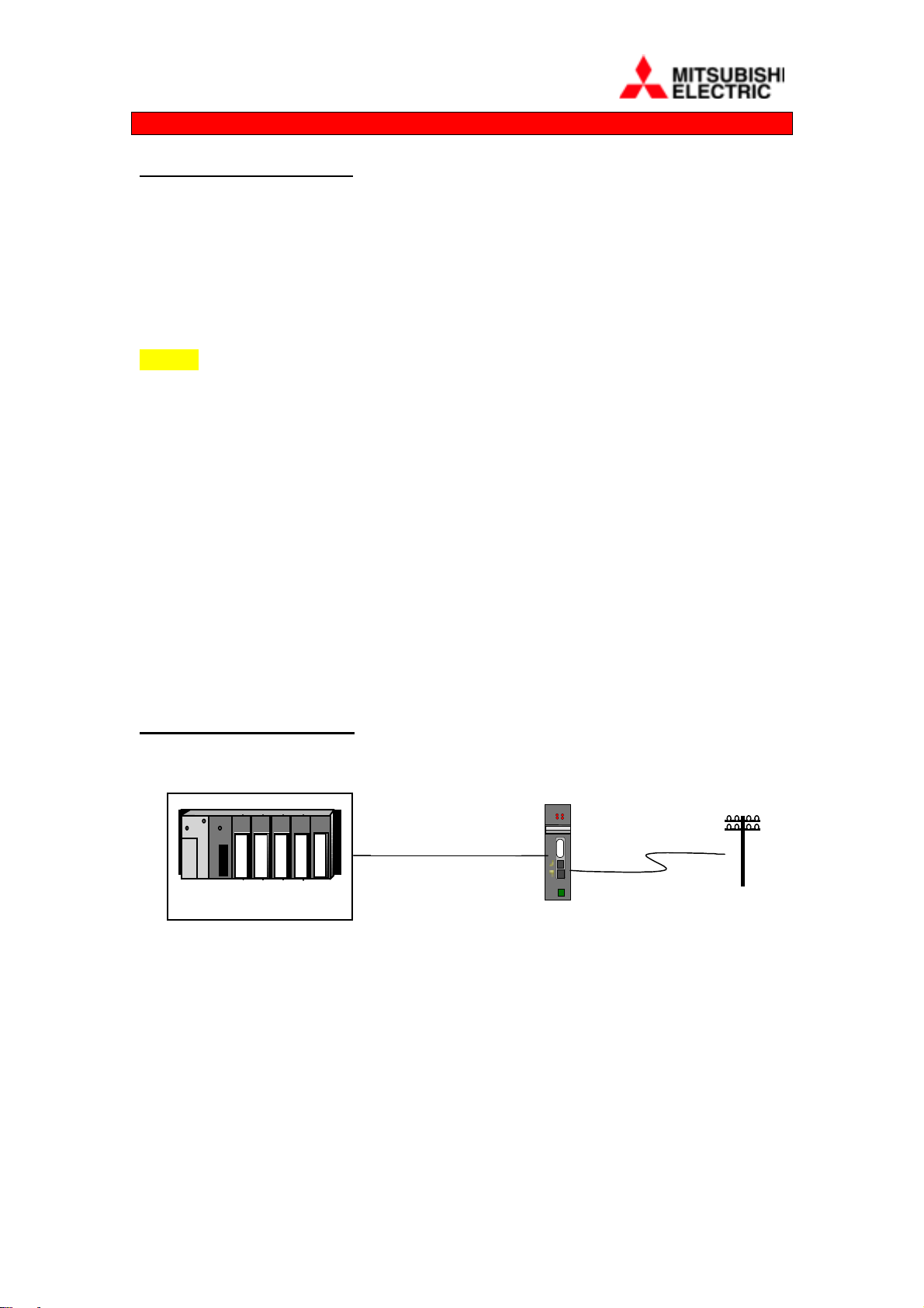
2.2.1 Connection to a Link module (eg. A1SJ71C24-R2)
Modem-A2S
RD
CD
MODEM-R2-
AnS/QnS/A via C24 (R2)
DATA
RS232
VOICE
LINE
24V
OV
i) Connect the 9-pin to 9-pin cable type (MODEM-R2-CAB), between the
Data RS232 port on the front of the DIN-MODEM-2 or A2S-MODEM and
to the RS232 connector on the front of the A1SJ71C24-R2 link module.
ii) Connect the telephone lead provided by plugging in the RJ11 type plug into
the socket labelled LINE, making sure that the connector is properly latched.
iii) When simultaneous voice and data is required, connect a suitable handset or
headset by plugging into the socket labelled VOICE.
iv) Connect a 24V or 12V dc supply via the connector provided. The dc
polarity is not important as it is corrected within the MODEM.
3
continued
S
T
O
2.2.1
NOTE 1: Modems cannot be connected directly to the CPU programming port.
NOTE 2: Set the Link module to protocol 1, Write during run, 9600 baud, 8 data bits,
No parity, 1 Stop bit and Sum Check ON. Eg. MODE=1, SW04,05,07,08 &12 = ON,
all other switches OFF. After changing these switches turn the power to the PLC off
MITSUBISHI
MODEM-FX2-CAB
FX1S/FX1N/FX2N
+ 232-BD
MODEM-PC9-CAB
and back on alternatively reset the CPU.
2.2.2 Connection to FX2N-232-BD
i) Connect a 9-pin male to 9-pin female cable, type MODEM-FX2-CAB or
MODEM-PC9-CAB, wired to the schematic shown in Section 7, between
the Data RS232 port on the front of the MODEM and the serial port at the
top of the FX2N-232-BD plug-in module.
ii) Then follow the instructions in Section 2.2.1 ii) to iv) above
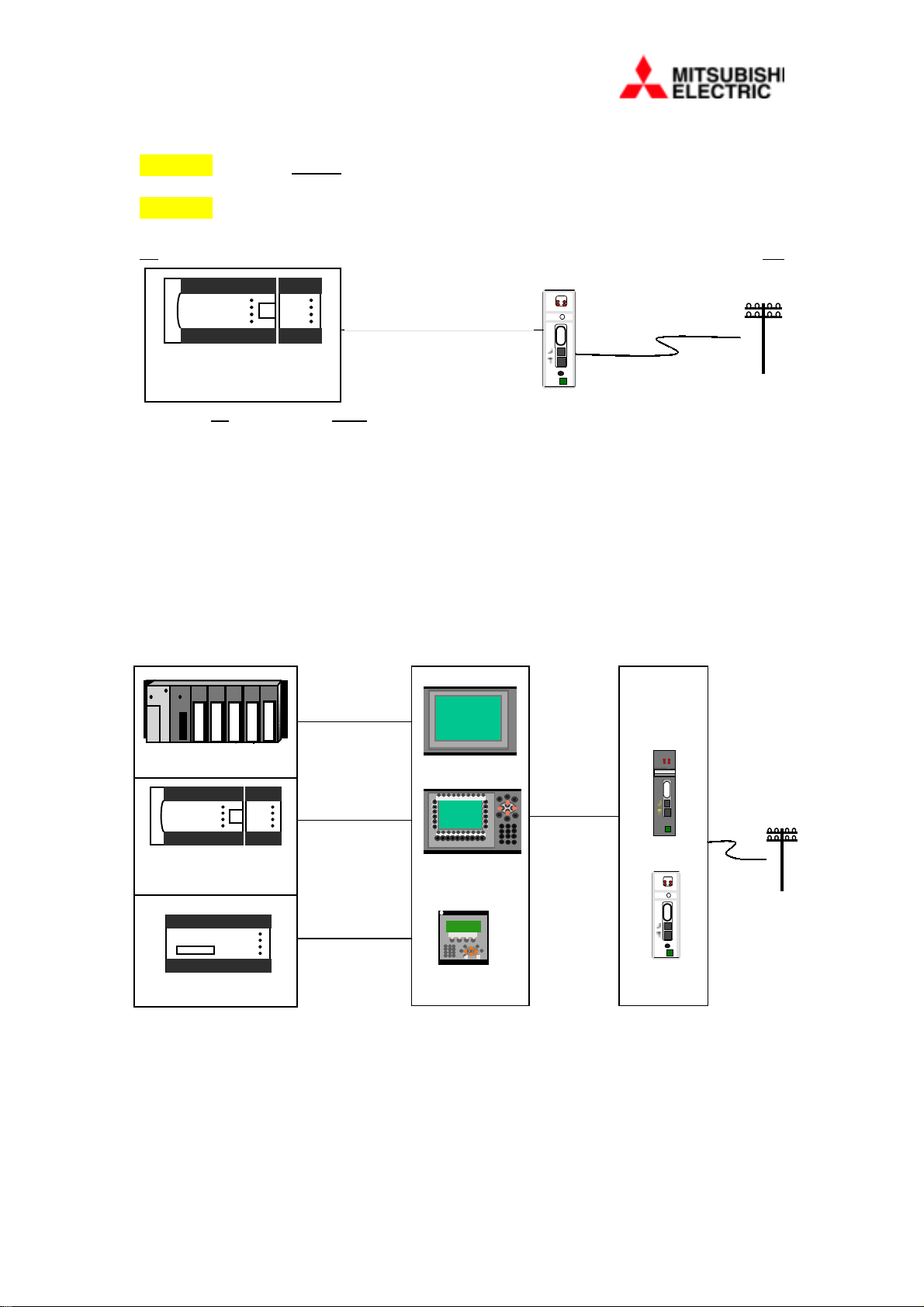
2.2.3 Connection to MAC 50/90 and E range of HMI’s
MAC 40+ CAB
Modem-A2S
RD
CD
OR
AnS/QnS/A
MITSUBISHI
MODEMMAC-CAB
FX-20P-CAB
CS
DATA
RS232
VOICE
LINE
24V
OV
FX0S/FX1S
FX0N/FX1N/FX2N
MAC 40+ CAB
MITSUBISHI
FX
iii) Connect a 9-pin male to 9-pin female cable, type MODEM-MAC-CAB,
wired to the schematic shown in Section 7, between the Data RS232 port on
the front of the MODEM and PRINTER serial port at the back of the MAC
or E range terminal.
iv) Then follow the instructions in Section 2.2.1 ii) to iv) above
4
2.2.4 Connection to FX-232AW / FX0N-232ADP
MITSUBISHI
MODEM-R2A-CAB
FX1S/FX1N/FX2N
+ FX2N-CNV-BD +
FX0N-232-ADP
MITSUBISHI
FX + FX-232AW
i)
Connect the 9-pin to 25-pin cable, type MODEM-R2A-CAB, between the
Data RS232 port on the front of the MODEM and the RS232C Connector
on the FX232AW / FX0N-232ADP module.
ii)
Then follow the instructions in Section 2.2.1 ii) to iv) above
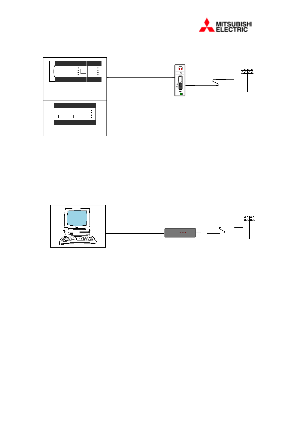
2.2.5 Connection to DESK Version
MODEM-PC9-CAB
i)
Connect the PC to Modem Data cable, type MODEM-PC9-CAB, between
the Data RS232 port at the rear of the MODEM and a spare
communication port on your PC.
ii)
Then follow the instructions in Section 2.2.1 ii) to iv) above.
logilink
336
RDSDCDTRCSOH
5

2.2.6 Wiring 24V dc Supply A2S and DIN Versions
i)
ii)
12V dc Supply DESK Version
i)
2.3 Initial configuration
Wire 24 dc from a suitable supply, usually from terminals on a nearby
module to the miniature screw terminal plug provided.
Check the specification for the 24V supply before making connection.
However, reversing the polarity of the dc will cause no harm.
Plug the 12V dc power supply provided into a mains supply and connect
the jack plug into the connector at the rear of the MODEM.
i)
ii)
Set the Modem to the correct local protocol (see 5.9 for a list of codes),
with the command:
AT%ADP=x (where x = protocol setting)
Read section 3.1 for more details.
6

Section 3 – Using the Enhanced Functions
In order to configure your modem and use its enhanced functions it must be connected
to the serial port of a PC running terminal software such as Terminal, HMI Tools
\Modem, Hyper-Terminal or ProComm Plus. This section describes how this is done.
3.1 Setting the Modem with Terminal Software The modem is pre-set to communicate at 9600 Baud with 8 data bits, 1 stop bit and
No parity. Flow control or Hardware Handshake is OFF. The terminal software must
therefore be set to match these parameters in order to communicate at all.
eg. 9600,8,N,1
3.1.1 Connecting the Modem to a PC
To connect the modem to a PC, use a suitable RS232 modem cable (accessory
MODEM-PC9-CAB), wiring for such a cable is shown in section 7.2.3.
When the modem is connected, any characters typed at the terminal software will be
echoed back by the modem.
When the modem is communicating with PC terminal software it can be configured
using AT commands, so called because they are all preceded with the letters AT. A
full list of these commands is given in section 5. The modem is supplied with all
essential parameters for plug and pla y already set, but if t hese are lost for any reason
the device can be reprogrammed with the following command string:
AT&F&D0S0=1 &W0 (all 0’s are zeros)
or
AT%F (version 1.20 or later)
3.1.2 Configuring the Modem
Before the modem can be connected to a PC/Laptop, PLC or an HMI it will be
necessary to set the modem to the correct protocol. Just as the HMI, for example,
requires to know what PLC it is connected to, the modem has special protocol settings
for different configurations. Refer to
the following command string,
AT%ADP=x (x = protocol setting)
Example 3-1 Protocol settings
AT%ADP=0 (or 1) Modem connected to a PC/Laptop (default)*
AT%ADP=3 Modem connected to an FX PLC
AT%ADP=A Modem connected to an AnS PLC via an E HMI
section 5.9 for a list of protocol settings and use
* Earlier versions before 1.20 were set to protocol 1.
7

3.2 Automatic Simultaneous Voice and Data
To use the ASVD function, simply plug a suitable handset or headset into the front
panel socket marked with a handset symbol. Voice and data communication will be
made automatically during the period that the modem is connected.
3.2.1 Using Simultaneous Voice and Data with Other Modems
Not all modems available support simultaneous voice and data functions. First ensure
that the other modem is capable of supporting this feature. Refer to the other
modem’s handbook to see if it supports analogue or Audio Span voice and data.
NOTE:
It is highly recommended that the ASVD feature be always used when any on-line
changes are made to the PLC code. A risk of damage to equipment connected to the
PLC or even injury may occur if alterations are made to the program or data without
continuous voice contact with a local operator.
8
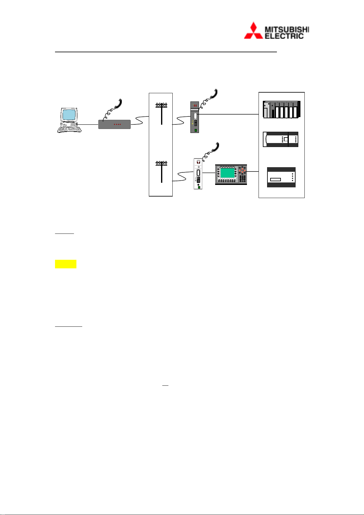
3.3 Online Maintenance Using Mitsubishi PLC Programming Software
24
LINE
One of the most commonly used features of th e modem is to contact a remote PLC
and then use programming software to interrogate operation. To do this requires a
two-stage operation.
Modem-A2S
RD
CD
CS
DATA
RS232
logilink
336
RDSDCDTRCSOH
VOICE
OV
MITSUBI
SHI
FX0S/FX1S
FX0N/FX2N
MITSUBI
SHI
FX
3.3.1 Making a Connection
Firstly, with the modem connected to your PC running terminal software, dial the
remote modem. Entering the command ATD followed by the telephone number of
the remote site is one way of doing this.
NOTE: Ensure the settings in the terminal software have been set to 9600,8,N,1.
Example 3-2 Dialling
ATD 0123456789 <enter> to dial a site on 0123456789
ATDT 0123456789 <enter> forces tone dialling (default)
ATDP 0123456789 <enter> forces pulse dialling
Secondly, close the terminal application (do not minimise). The modem will hold the
connection. Then run your Mitsubishi programming software from Windows, for
example, GPPWIN.
3.3.2 Terminating a Call
To terminate the connection, exit the programming software and r estart the terminal
application. Then select “Hang-up” or type:
+++ (3 pluses) followed by a pause of at least 1 second, or until the modem returns
“OK”
Then type ATH <enter> to ‘hang up’, the modem will close the connection and go onhook.
If the modem does not respond with OK after the three + symbols, try again.
9

3.3.3 Communicating with Mitsubishi PLC’s
Using the A2S/DIN/DESK Modems you will be able to transfer data between a
PC/Laptop and a PLC, seamlessly without making any changes to the default settings
in the HMI or Programming software. The modem can be connected directly to the
PLC via a suitable RS-232 interface or through an HMI port in the “Transparent”
mode, refer to section 2.
A simple test would be that if you are able to programme or monitor the PLC or HMI
when directly connected using the appropriate cable, then the same settings will apply
for the A2S Modems. The intelligence within the modem automatically adjusts
formats, even speeds to suit the individual PLC and HMI configuration. These unique
features, for example, include the ability to recognise when the software is addressing
the HMI and allow “high speed” data transfers.
3.3.4 Communicating with E series and MAC HMI’s
There are two methods of communication between the HMI and PC using Modems.
a) Method 1 (preferred):
Using two Mitsubishi A2S/DIN/DESK MODEMs at both ends.
This unique method provides the following features:
• transfer rates of up to 38400 baud.
• uses default software settings
• allows switching between HMI and PLC without having to redial.
NOTE:
1) Prior to installation, each modem must be set to a protocol matching the local
device with the protocol command, for example, AT%ADP=F for FX series and A
for A/Q series via HMI, refer to section 3.1.
2) If “HMI File transfers” (see section 3.3.5) are also required, when the HMI is
connected to an FX series PLC,
9600,8,N,1. This can be altered via the HMI software in “Set-up/Peripherals” or
via the HMI Front Panel.
Firstly, make connection in the normal way, (see 3.3.1, above), then close the
Terminal application (do not minimise).
Secondly, load the HMI programming software and select the speed “settings” to a
baud rate up to 38400 then, with the “Automatic terminal RUN/PROG” selected,
Transfer your Project in the normal way.
After each successful transfer the modems will automatically return to 9600 baud to
allow normal transparent mode to take place.
the RS232 port in the HMI must be changed to
b) Method 2:
Dialling from another manufacturers make of modems connected at the PC end.
Firstly, select 2400 baud in the terminal software before making a connection then
close the Terminal application (do not minimise).
10

Secondly, load the HMI programming software and adjust the speed ‘Settings’ to
2400 baud in the ‘Transfer \ Project’ window before starting the transfer.
NOTE: After each successful transfer the call must be terminated and redialled at
9600 baud before normal transparent mode to the PLC can be resumed.
CAUTIONARY NOTE:
At the time of writing. it is only possible to communicate with the E range and certain
versions of the MAC range of HMI’s, using either method 1 or 2.
3.3.5 Transferring files from/to the HMI
It is also possible to download files held in the E HMI, for example, “Trends”,
“Recipes” and “Alarm Lists”. To do this requires the HMI to be dialled from the
Windows HMI Tools program “Filetran”.
Firstly, enter your telephone numbers in the Connections list by selecting ‘Edit’,
under ‘Options\Comm Settings’. Then check that the communication is set to
9600,8,N,1.
a) Method 1 (preferred):
Using two Mitsubishi A2S/DIN/DESK MODEMs at both ends.
To dial your chosen telephone number click ‘Connect’ and wait for the Files to be
displayed before selecting the files to receive or send..
To “Hang-up”, click on the ‘Close’ button and the modems will return to their normal
“command mode” state.
b) Method 2:
Dialling from another manufacturers make of modems connected at the PC end.
Firstly, make sure that the RS232 port in the HMI is set to 9600,8,N,1 then dial as
described in
NOTE:
The RS232 port in the HMI will need to be changed back to the FX or AnS format
every time it is required to program a PLC through the transparent mode.
3.3.6 Communicating with other makes of PLC controllers
Because the purpose of the Modems’ on-board intelligence is to communicate
specifically with the Mitsubishi range of PLC’s there may be some difficulty in
transferring data between other makes. Until a local protocol has been written for the
device being connected, setting another code will confuse the modem and it will
incorrectly convert the serial format.
method 1
, above.
To allow the A2S type modem to be used for non-Mitsubishi equipment, for example
On-line Maintenance operation, it will be necessary to set the remote A2S Modem
into the special transparent protocol, as follows:
11
 Loading...