

Mitsubishi A2CCPU User Manual
REVISIONS
%The manual number
is
given on the
bottom
left
of
the
back
cover.
Print
Date
Mav.
1990
'Manual
Number
~
IB
(NA)
66238-A
Rwkion
First
edition
Thank you for choosing the Mitsubishi MELSEC-A Series
of
General Purpose Programmable
Controllers. Please read this manual carefully
so
that the equipment
is
used to its optimum.
A copy
of
this manual should
be
forwarded
to
the end User.
1
3
7
4
4.4
4.5
4.6
4.7
4.8
..
5.1
5.2
5.3
5.4
Appendix 1
Appendix 2
Appendix 3
Appendix 4
Appendix
5
1.
lNTRooUcTl0N
/MELSEC-A
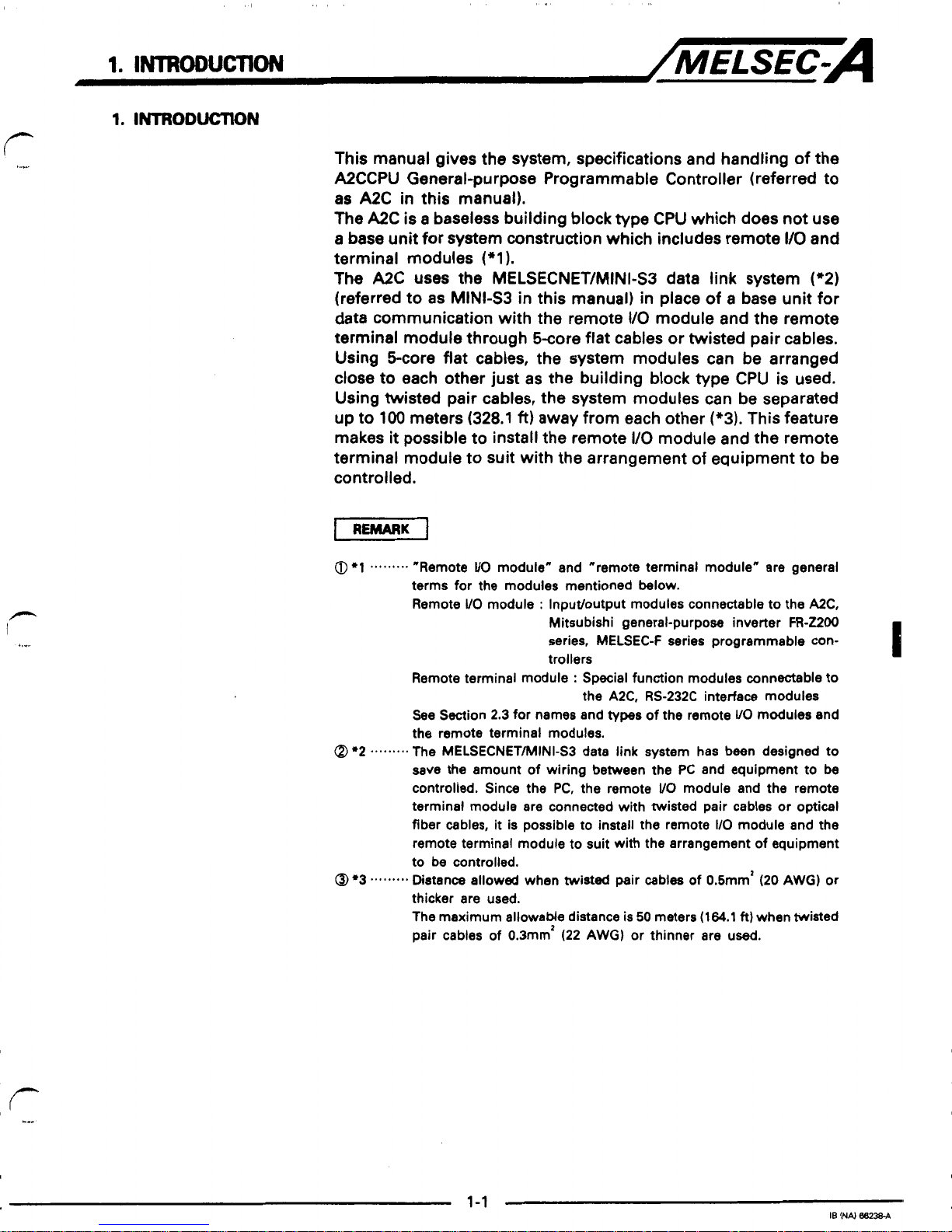
This manual gives the system, specifications and handling of the
A2CCPU General-purpose Programmable Controller (referred to
as
A2C
in
this manual).
The
A2C is a baseless building block type CPU which does not use
a
base
unit
for system construction which includes remote
110
and
terminal modules
(*1).
The
A2C uses the MELSECNET/MINI-S3 data link system
(*2)
(referred to as MINLS3
in
this manual)
in
place
of
a
base unit for
data communication with the remote
VO
module
and
the remote
terminal module through 5core flat cables or twisted pair cables.
Using Score flat cables, the system modules can be arranged
close to each other just as the building block type CPU is used.
Using twisted pair cables, the system modules can be separated
up to
100
meters (328.1
ft)
away from each other
(*3).
This feature
makes
it
possible to install the remote I/O module and the remote
terminal module to suit with
the
arrangement of equipment to be
controlled.
I
REMARK
0
l
.........
"Remote
VO
module" and "remote terminal module" are general
terms for the modules mentioned below.
Remote
VO
module : Input/output modules connectable to the A2C,
Mitsubishi general-purpose inverter FR-ZZOO
series, MELSEC-F series programmable controllers
I
Remote terminal module : Special function modules connectable to
See Section 2.3 for names and
types
of the remote
VO
modules and
the remote terminal modules.
save the amount of wiring between the PC and equipment to be
controlled. Since the PC, the remote
VO
module and the remote
terminal module are connected with twisted pair cables or optical
fiber cables,
it
is possible to install the remote
I/O
module and the
remote terminal module to suit with the arrangement of equipment
to be controlled.
thicker are used.
The maximum allowaMe distance is
50
meters
(164.1
ft)
when twisted
pair cables of 0.3mm' (22 AWG) or thinner are used.
the A2C, RS-232C interface modules
Q
.2
.........
The MELSECNET/MINI-S3 data link system has been designed to
@
c3
...
......
Distance allowed when
twisted
pair cables of 0.Smm2 (20 AWG)
or
1.
INTRODUCTION
/MELSEC-A
1.1
General Description
of
Operation
This section describes the data communication between the
A2C,
the remote
I/O
module and the remote terminal module.
See
Section
4.2
for the
A2C
functions.
1.1.1
ON/OFF
data
communication between
the
A2C
and
the
remote
I/O
module
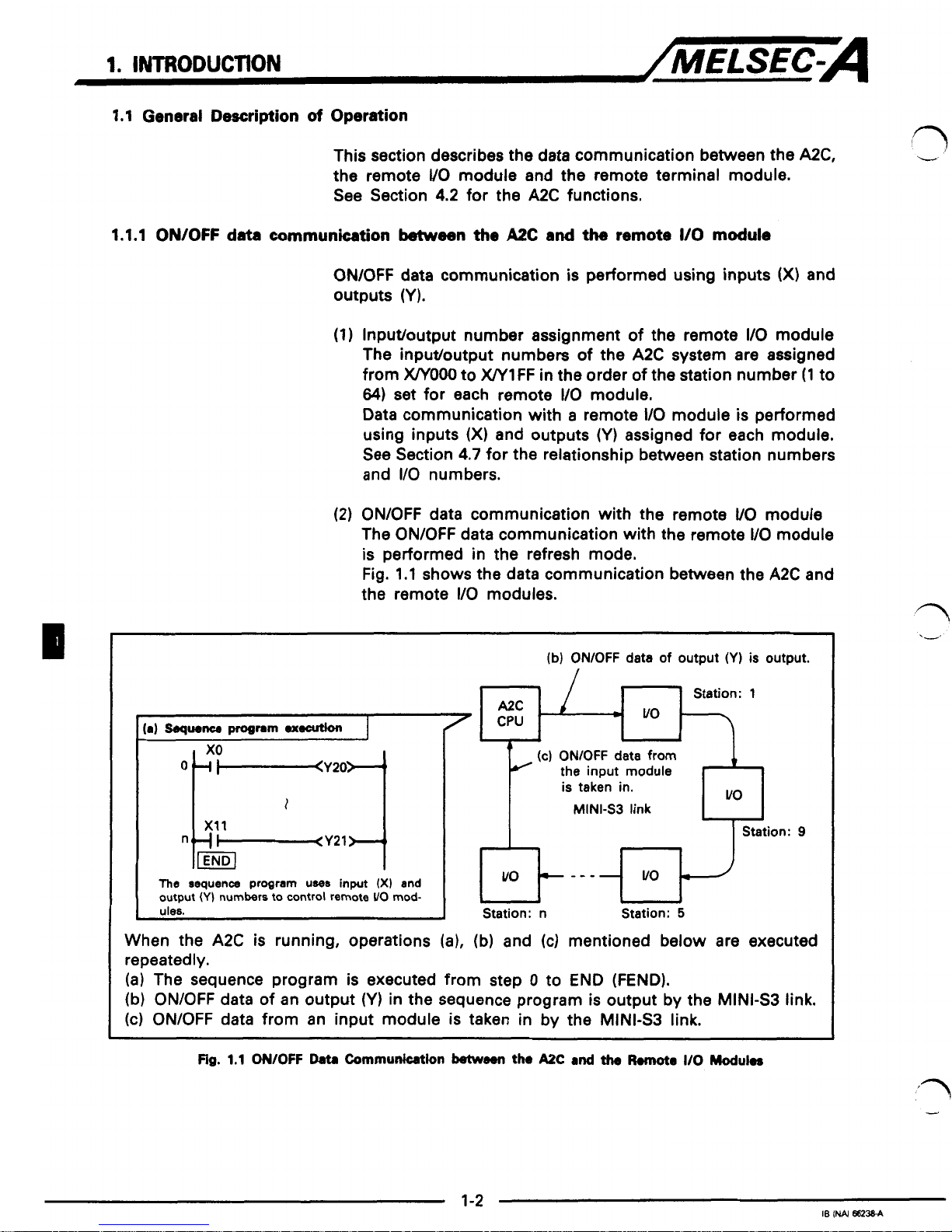
ON/OFF data communication
is
performed using inputs
(X)
and
outputs
(Y).
(1)
Inputloutput number assignment
of
the remote
I/O
module
The inputloutput numbers
of
the
AX
system are assigned
from
X/YOOO
to
W1
FF
in the order of the station number
(1
to
64)
set
for each remote
110
module.
Data communication with
a
remote
I/O
module
is
performed
using inputs
(X)
and outputs
(Y)
assigned for each module.
See Section
4.7
for the relationship between station numbers
and
I/O
numbers.
(2)
ON/OFF data communication with the remote
VO
module
The ON/OFF data communication with the remote
I/O
module
is
performed in the refresh mode.
Fig.
1.1
shows the data communication between the
AX
and
the remote
I/O
modules.
t
I
The
sequence
program
UWE
input
(X)
and
output
(Y)
numbers to control remote
UO
mod-
I
(b)
ONIOFF
data
of
output
(Y)
is
output.
/
(c)
ONlOFF
data
from
the input module
is taken in.
MINI-S3
link
Station: n Station:
5
When the
A2C
is
running, operations
(a),
(b)
and
(c)
mentioned below are executed
repeatedly.
(a)
The sequence program is executed from step 0 to END (FEND).
(b)
ON/OFF data of an output
(Y)
in
the sequence program
is
output by the MINI43 link.
(c)
ON/OFF data from an input module
is
taken in by the MINIS3 link.
Fig.
1.1
OWOFF
Data
Communication
between
th.
AZC
and
the
R.mote
I/O
Modukr
1
I
1
3
??
‘I’
1
1
1
1
1.
INTR0DUCTK)N
/MELSEC-A
Input/output response time
The data communication response time bwteen the
A2C
and
the remote
VO
modules
is
as
described below.
i
/+--
.x
To
take
in an
ON/OFF
change from the input module,
1
scan
at
maximum
is
required.
When an output
ON/OFF
is
changed by the sequence
program,
1
scan
at
maximum
is
required to output the
change to the output module.
When
ON/OFF
control of the output module
is
done by
ONIOFF
data
of
the input module, 2 scans
at
maximum are
required
till
the
ON/OFF
status of the output module
changes after an
ON/OFF
input changed.
1.
INTRoDuCTtoN
/MELSEC-A
1.1.2
Data
communication
betweem
the
A2CCPU
ad
the remote terminal module
(1)
Maximum number of remote terminal modules to be connected
A maximum of
14
remote terminal modules can be connected
to the A2C.
(2)
Data communication with remote terminal modules
(a) Perform the following initial setting.
1)
The first station number of the remote terminal module
2)
Protocol
See Section
4.2.9
for details of initial setting.
(b) Execute data communication with the
FROM0
instruc-
tion.
See the ACPU Programming Manual (Common Instruc-
tions) for details of the FROM/TO instruction.
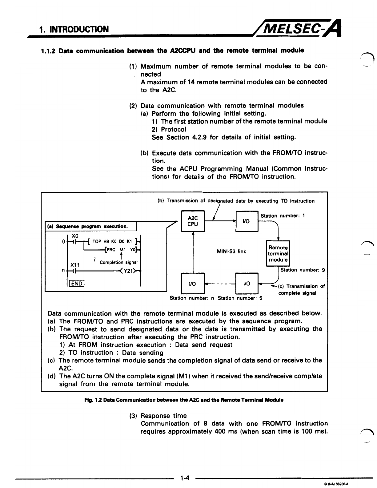
(b)
Transmission
of
designated data
by
executing TO instruction
CPU
I
A
MINI-S3
link
Remote
terminal
n
7-
Station number:
9
U
I
Station number: n Station number:
5
complete signal
Data communication with the remote terminal module is executed
as
described below.
(a)
The
FROM/TO
and PRC instructions are executed by the sequence program.
(b) The request to send designated data
or
the data is transmitted by executing the
FROM/TO
instruction after executing the PRC instruction.
1)
At
FROM
instruction execution : Data send request
2)
TO instruction : Data sending
A2C.
signal from the remote terminal module.
(c) The remote terminal module sends the completion signal of data send or receive to the
(d) The A2C turns
ON
the complete signa.1
(Ml)
when
it
received the sendreceive complete
Fig.
1.2
Data
Communhtion
between
the
Ax
and
the
Rmote
Terminal
Module
(3)
Response time
Communication of
8
data with one
FROM/TO
instruction
requires approximately
400
ms (when scan time is 100 ms).
1
,?
1
1
1
1
I
1
I
4
"I
.-
1
3
I
7
1
i.1
-1
1
The
A2C
has the following features.
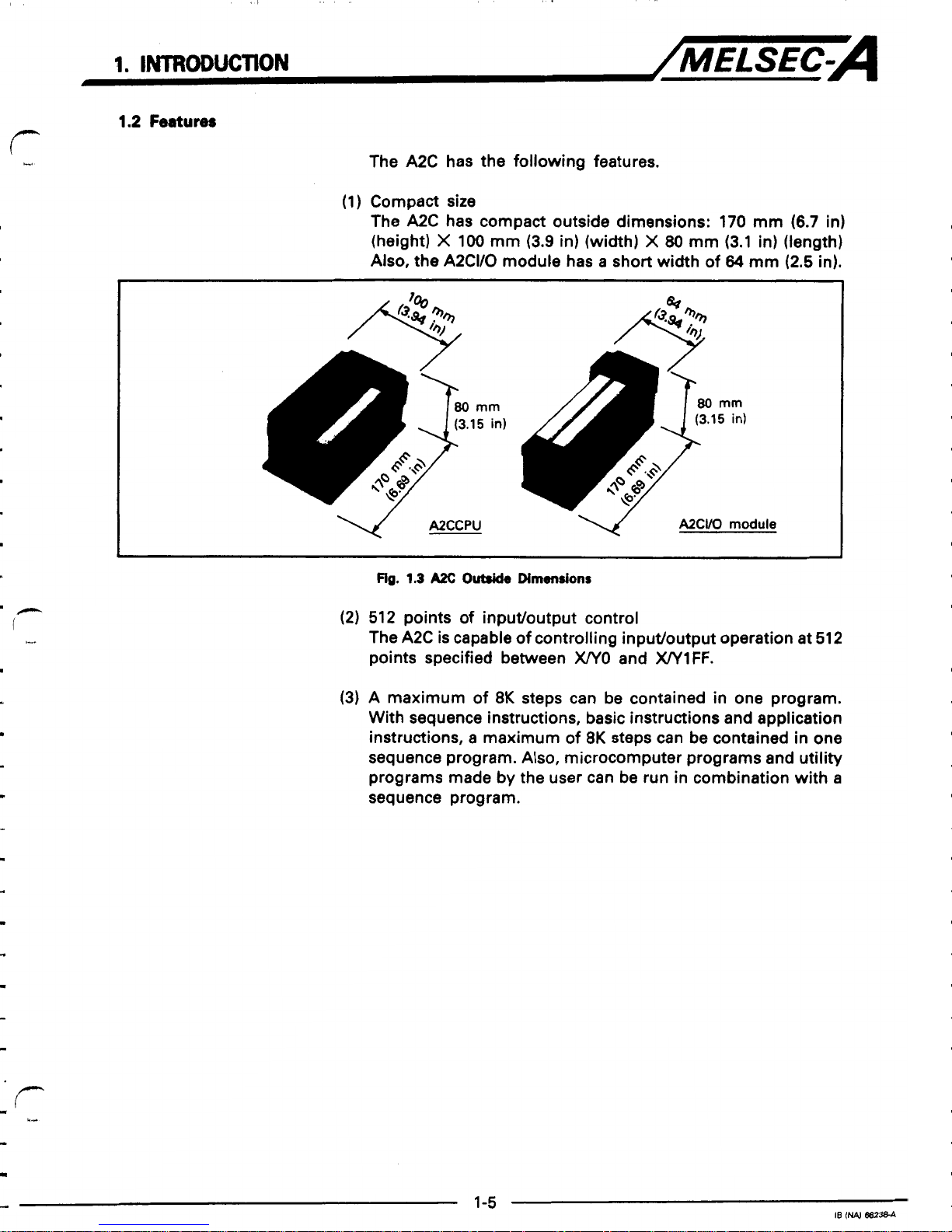
(1)
Compact
site
The A2C has compact outside dimensions:
170
mm
(6.7
in)
(height)
X
100
mm
(3.9
in) (width)
X
80
mm
(3.1
in) (length)
Also,
the
A2CI/O
module has a short width of
64
mm
(2.5
in).
A2CCPU
NCVO
module
1
Fig.
1.3
AX
0-
Dimensions
(2)
512
points of input/output control
The
A2C
is
capable of controlling input/output operation at
512
points specified between
XPlO
and
WlFF.
(3)
A
maximum of
8K
steps can be contained in one program.
With sequence instructions, basic instructions and application
instructions,
a
maximum of
8K
steps can be contained in one
sequence program. Also, microcomputer programs and utility
programs made
by
the user can be run in combination with
a
sequence program.
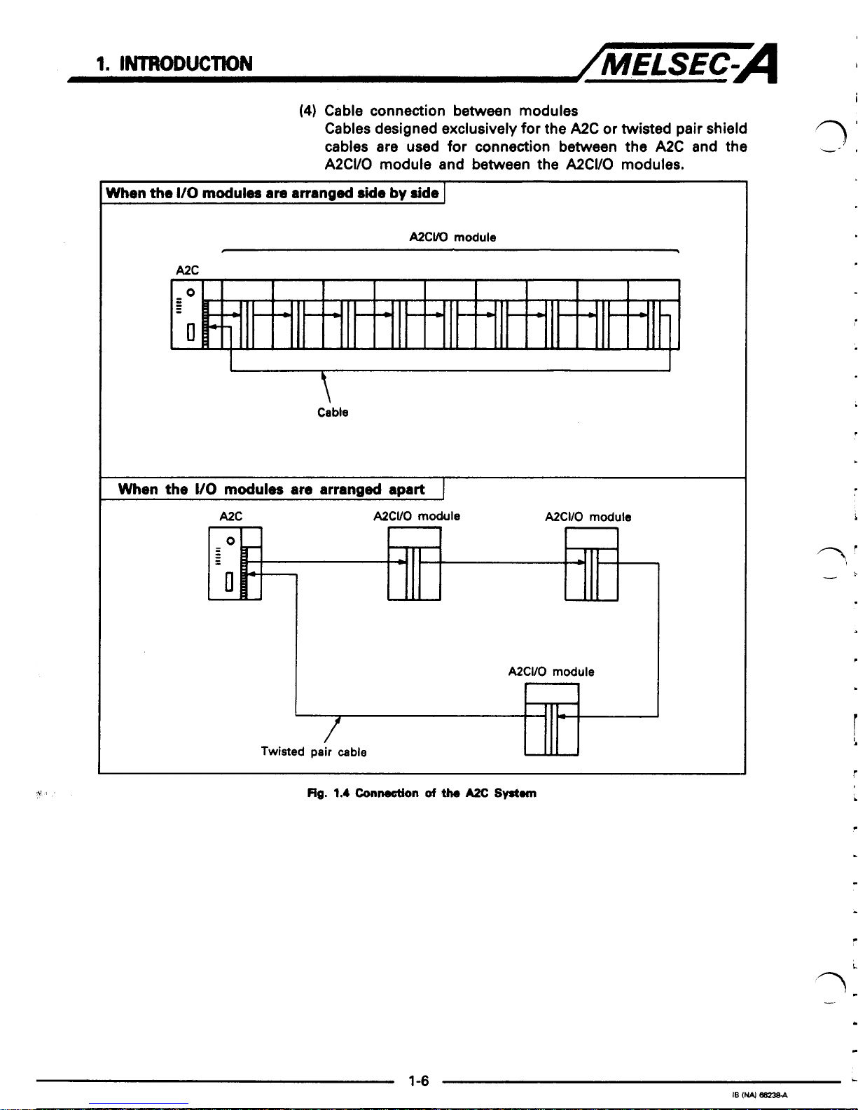
(4)
Cable connection between modules
Cables designed exclusively for the A2C or twisted pair shield
cables are used for connection between the
A2C
and the
A2CI/O module and between the A2CWO modules.
When
the
I/O
modules
are
arranged
Me
by
side
1
AXVO
module
A2C
\
Cabte
1
When
the
UO
modules
are
arranged
apart
1
A2C
A2CVO
module
A2CI/O
module
7
d
rl
I
3
3
Rg.
1.4
Connection
of
the
Ax
Swan
i
-'
1
1-6
J
IB
(N4
682364
1.
INTRODUCTION
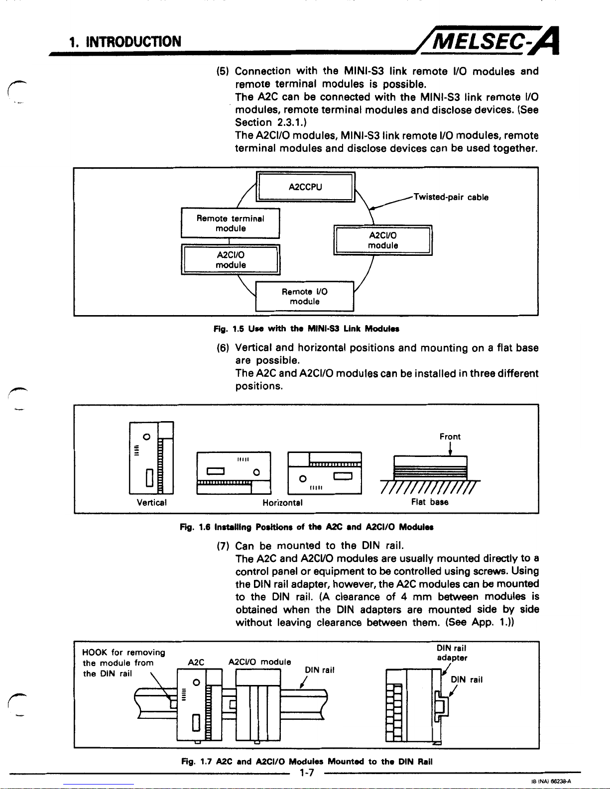
(5)
Connection with the
MINI43
link remote
I/O
modules and
remote terminal modules is possible.
The A2C can be connected with the MINi-S3 link remote
I/O
modules, remote terminal modules and disclose devices. (See
Section 2.3.1
.)
The A2CI/O modules, MINI-S3 link remote
I/O
modules, remote
terminal modules and disclose devices can be used together.
/I=
A2CCPU
Twisted-pair
cable
Remote terminal
module
I
-1
E
module
Remote
UO
module
Fig.
1.5
Use
with
the
MINI-s3
Link
Modules
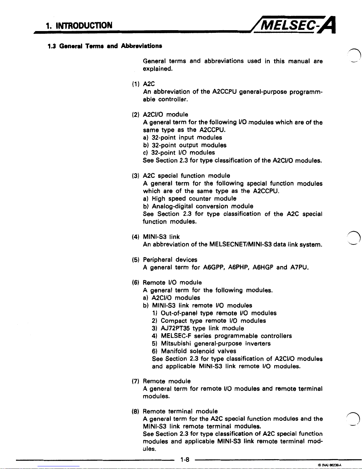
(6)
Vertical and horizontal positions and mounting on a flat base
are possible.
The A2C and A2CI/O modules can be installed
in
three different
positions.
I1111
0
0
I
.....
I
Vertical Horizontal
Flat
base
~~ ~~~~
FQ.
1.6
Installng
Positions
of
the
Ax
and
A2CI/O
Modulw
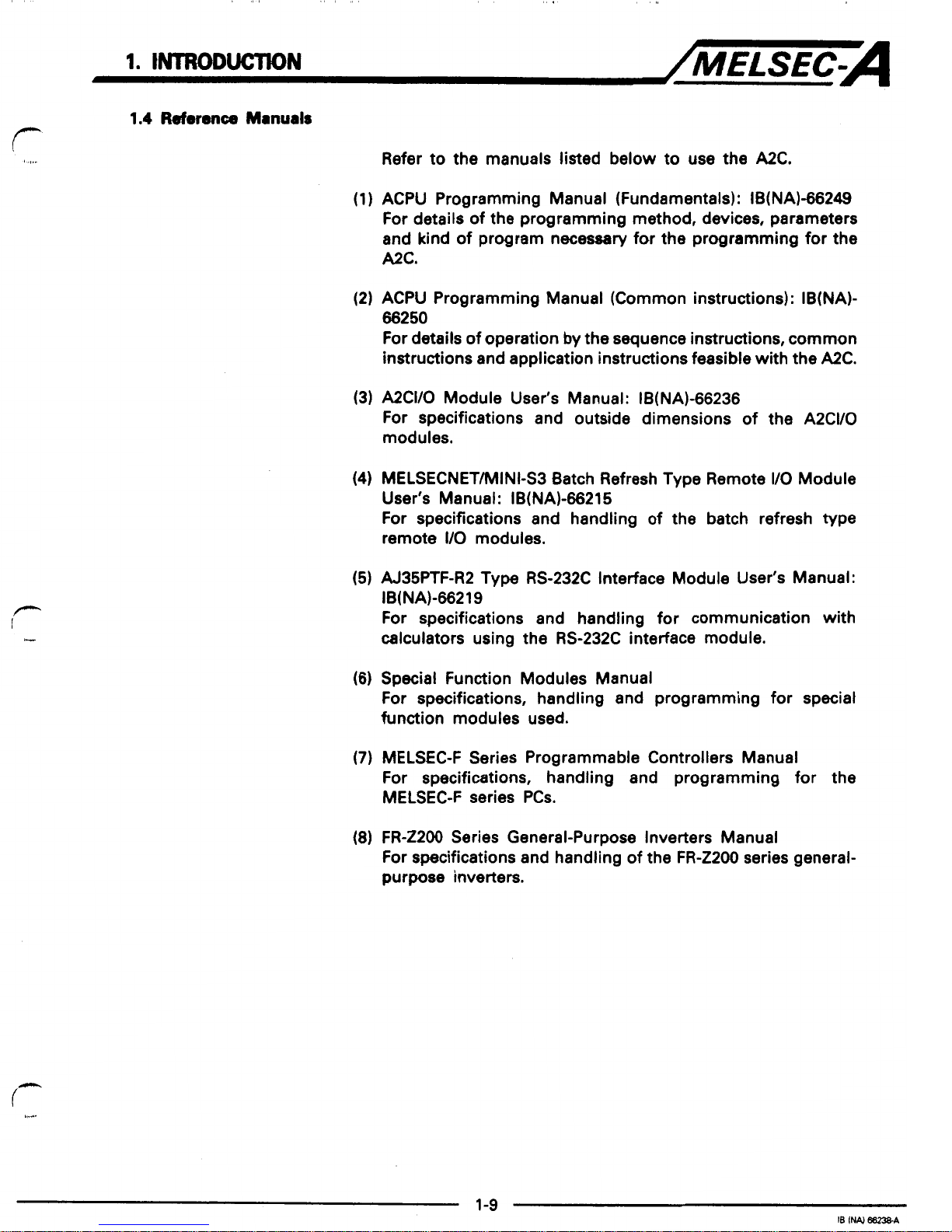
(7)
Can be mounted to the DIN rail.
The A2C
and
A2CUO
modules are usually mounted directly to
a
control panel
or
equipment to
be
controlled using screws. Using
the DIN rail adapter, however, the A2C modules can
be
mounted
to the DIN rail. (A clearance of
4
mm between modules is
obtained when the DIN adapters are mounted side
by
side
without leaving clearance between them.
(See
App. 1.))
HOOK
for removing
the module from
A2C
A2CUO
module
!
the
DIN
rail
DIN
rail
adapter
Fig.
1.7
A2C
and
A2CI/O
Modules
Mounted
to
the
DIN
Rail
1.
INTRODUCTlON
/MELSEC-A
1.3
GenW
Tmr
and
Abbreviations
General terms and abbreviations used
in
this manual are
explained.
A2C
An abbreviation of the A2CCPU general-purpose programmable controller.
A2CUO module
A general term for the following
UO
modules which are of the
same type as the A2CCPU.
a) 32-point input modules
b) 32-point output modules
c) 32-point
I/O
modules
See
Section 2.3 for type classification of the A2CVO modules.
A2C
special function module
A general term for the following special function modules
which are of the same type as the A2CCPU.
a)
High speed counter module
b) Analog-digital conversion module
See Section 2.3 for type classification of the A2C special
function modules.
MINI-S3 link
An abbreviation of the MELSECNET/MINI-S3 data link system.
Peripheral devices
A
general term for A6GPP, AGPHP, A6HGP and A7PU.
Remote
UO
module
A general term for the following modules.
a)
A2CI/O modules
b)
MINI43 link remote
UO
modules
1)
Out-of-panel type remote
I/O
modules
2) Compact type remote
I/O
modules
3) AJ72PT35 type link module
4)
MELSEC-F series programmable controllers
5) Mitsubishi general-purpose inverters
6) Manifold solenoid valves
See Section 2.3 for type classification of A2CI/O modules
and applicable MINI-S3 link remote
I/O
modules.
Remote module
A general term for remote
UO
modules and remote terminal
modules.
Remote terminal module
A general term for the A2C special function modules and the
MINI43 link remote terminal modules.
See Section 2.3 for type classification of A2C special function
modules
and
applicable MINI-S3 link remote terminal mod-
ules.
1-8
18
(NAI
i
1.
INTRODUCTION
/MELSEC-A
1.4
Referbnco
Mmuals
Refer to
the
manuals listed below to use
the
A2C.
(1) ACPU Programming Manual (Fundamentals): IB(NAl-66249
For details of the programming method, devices, parameters
and kind of program necessary for
the
programming for the
A2C.
(2) ACPU Programming Manual (Common instructions): IB(NA)-
66250
For details of operation by the sequence instructions, common
instructions and application instructions feasible with the A2C.
(3) A2CI/O Module User's Manual: IB(NAl-66236
For specifications and outside dimensions of the A2CI/O
modules.
(4)
MELSECNETMINI-S3 Batch Refresh Type Remote
I/O
Module
User's Manual: IB(NA)-66215
For specifications and handling of the batch refresh type
remote
I/O
modules.
(5) AJ35PTF-R2 Type RS-232C Interface Module User's Manual:
For specifications and handling for communication with
calculators using the RS-232C interface module.
IB(NA)-66219
(6)
Special Function Modules Manual
For specifications, handling and programming for speciat
function modules used.
(7)
MELSEC-F Series Programmable Controllers Manual
For specifications, handling and programming for the
MELSEC-F series PCs.
(8)
FR-Z2OO Series General-Purpose Inverters Manual
For specifications and handling of the
FR-ZZOO
series general-
purpose inverters.
2,
SYSTEM
CONRGURAflON
/MELSEC-A
2.
SYSTEM
CONflGURATlON
?
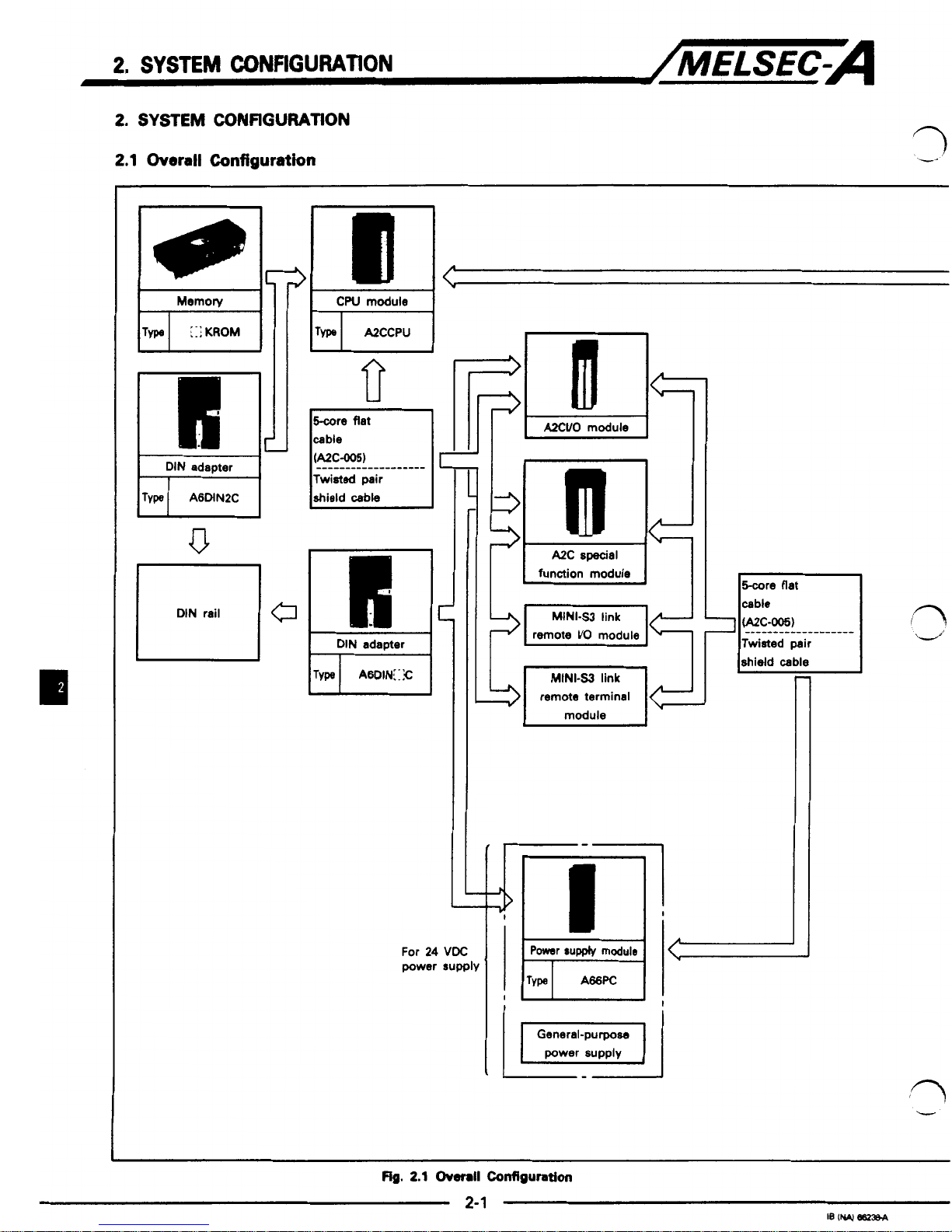
2.1
Overall
Configuration
,'
--
I
cw
module
I
I
DIN
adapter
I
L
II
II
L
L
For
24
VDC
power
supply
remote
br0
module
remote terminal
Twisted pair
shield
cable
1
I
41r!
I
ra
..-'
'n
'Y
2.
SYSTEM
CONFIGURATION
/MELSEC-A
Audio
recorder
+=
writer unit
‘2
95
writer
pLl
keyboard
system disk
‘4
c
Printers:
KGPR,
K?PR,
A7PR,
generalpurpose
printer
KGPR-K,
GT-10,
k==
user disk
SW4GP- GPPAEE
system disk
n
‘4
r-
SWO-FDC
clesning disk
hI
intelligent
A6GPPE
~
I
GPP
,-xq
composite
I
video cable
I
El
keyboard
I
REMARK
1
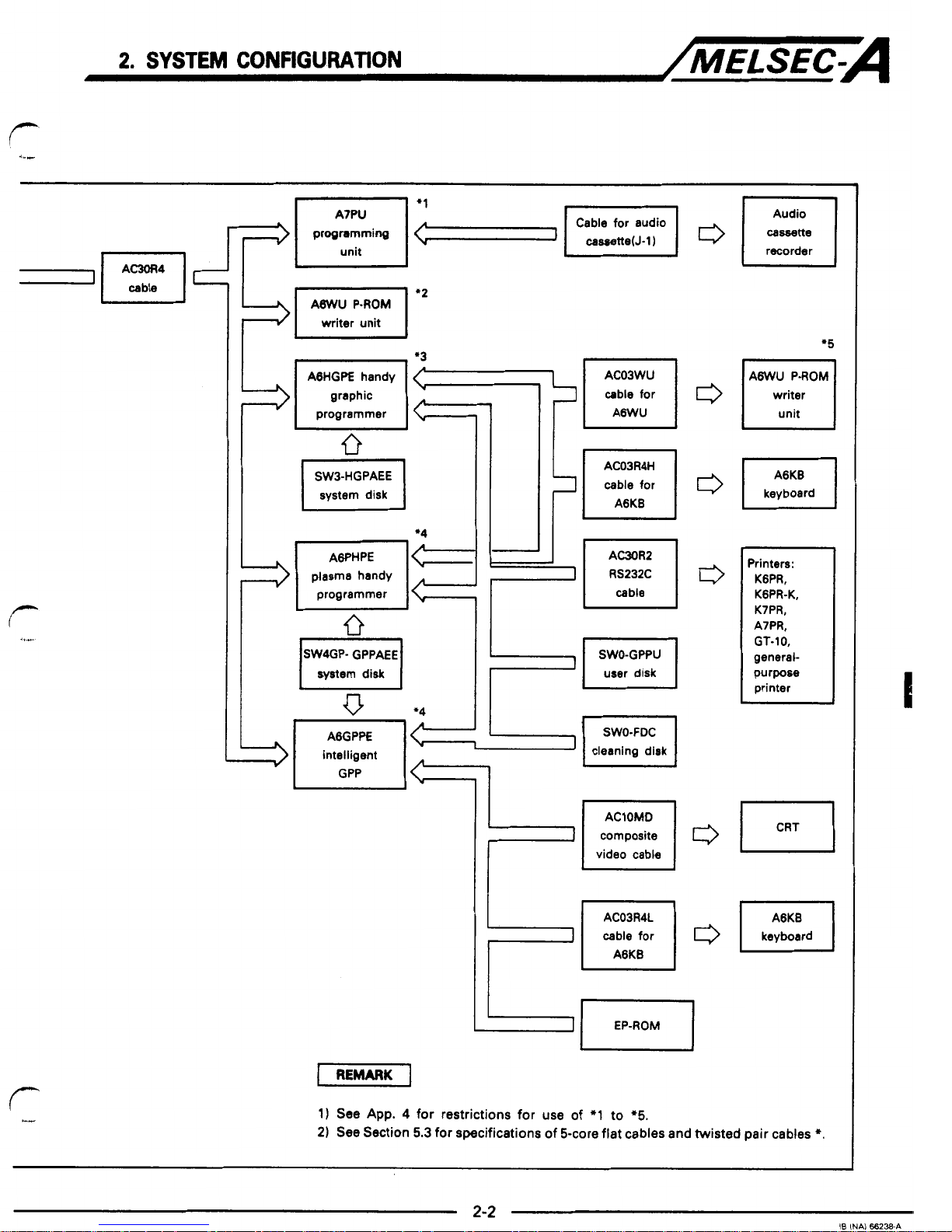
1)
See
App.
4
for restrictions for use of
*I
to
‘5.
2)
See Section
5.3
for specifications of 5-core flat cables and twisted pair cables
*.
2-2
18
INAi
66238A
2.
SYSTEM
CONFIGURATION
-/MELSEC-A
2.2
Notes
on
System Construction
(1) Connection
of
remote
I/O
modules and remote terminal
modules
A maximum
of
64
stations
of
remote
I/O
modules and remote
terminal modules can be connected to the A2C.
Also, the MINI-S3 link disclose devices can be connected. (See
Section 2.3.)
(2) Applicable remote terminal modules
A
maximum
of
14 remote terminal modules among those
mentioned below can be connected to the A2C. However,
when only the AJ35PTF-R2 RS-232C interface module is used,
up to
7
modules can be connected.
a)
A68ADC ND conversion module
b) AD61C high speed counter module
c) AJ35PTF-R2 RS-232C interface module (no-protocol mode
only)
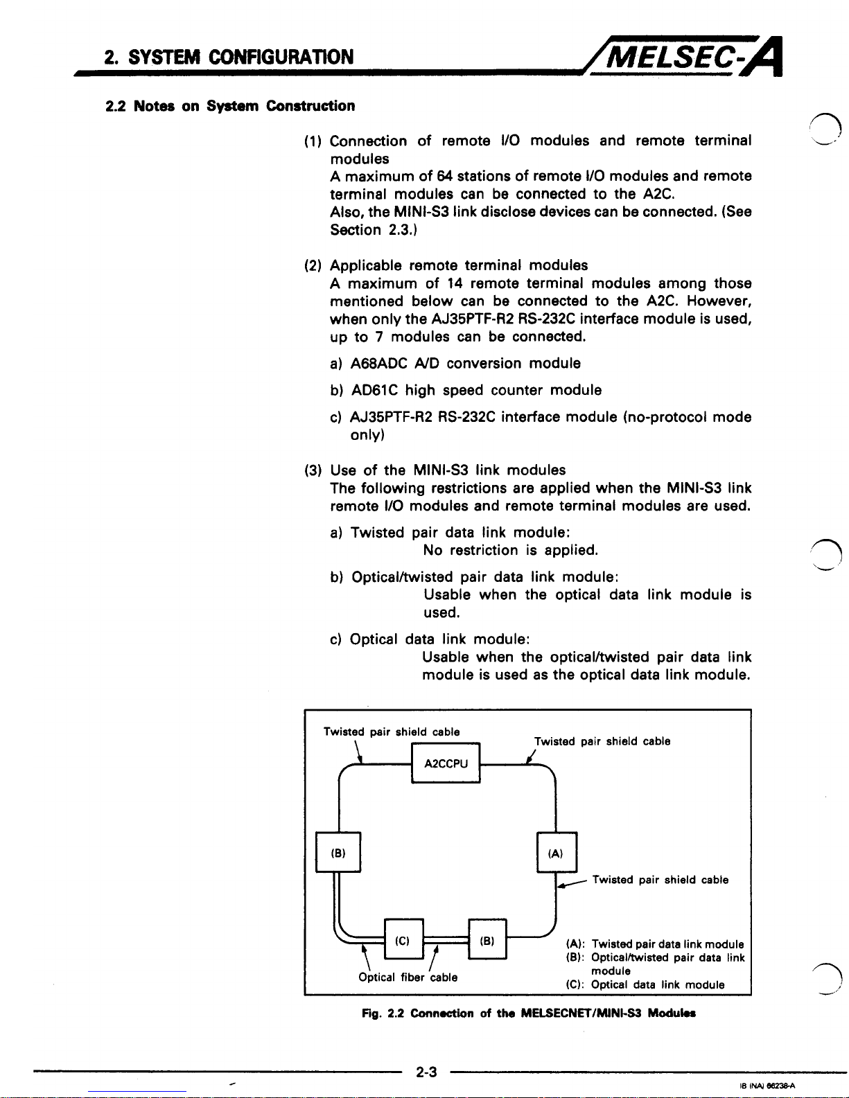
(3) Use
of
the MINI43 link modules
The following restrictions are applied when the MINI-S3 link
remote
I/O
modules and remote terminal modules are used.
a) Twisted pair data link module:
No
restriction is applied.
b) Opticalltwisted pair data link module:
Usable when the optical data link module is
used.
c) Optical data link module:
Usable when the opticalhisted pair data link
module is used as the optical data link module.
Twisted pair shield cable
Twisted pair shield
cable
A2CCPU
(A):
Twisted pair data link module
(8):
Opticalltwisted pair data
link
\
I
Optical fiber
cable
module
(C):
Optical data link module
Fig.
2.2
Cunnoction
of
the
MELSECNET/MINt-S3
Moduk.
(-'
ii.
2. SYSTEM
CONFIGURATON
/MELSEC-A
(4)
Power supply for the
A2CVO
module and the
A2C
special
function modules
The
A2CVO
modules and the
A2C
special function modules
require
24
VDC
power supply. Use the
A66PC
power supply
module or
a
general-purpose
24 VDC
power supply.
(5)
Both remote
I/O
modules and remote terminal modules, when
used with the
A2C,
need station number setting.
If
two
or more different modules are
set
for one same station
number, incorrect input and output will occur. Make sure that
there are no modules which are
set
for one same station
number before the power
is
turned
ON.
See Section
4.7
for details of station setting.
(6)
To
eliminate incorrect input
at
the remote
I/O
modules, design
the
A2C
system considering the following.
a)
Measures on turning
ON
and
OFF
the power
1)
When turning
ON
the power, turn
ON
the remote
I/O
modules first, and then, turn
ON
the
A2C.
Or, turn
ON
the
A2C
and the remote
I/O
modules together
at
the
same time.
2)
When turning
OFF
the power, turn
OFF
the
A2C
first, and
then, turn
OFF
the remote
I/O
modules.
Or,
turn them
OFF
together
at
the same time.
Power supply for the remote
110
modules indicates the following.
1)
UO
module power supply: Power supplied to the
WO
moudle power supply is
converted to
5
VM:
inside the system and used in the internal circuit of the
I/O
module.
2)
Input external power supply: Power supply for input modules
3)
Output external power supply: Power supply for output modules
See the following manual for details.
A2WO
Module User's Manual
2.
SYSTEM
CONffiURATION
/MELSEC-A
b)
Measures againt momentary power failure for the
1/0
module
Momentary power faiture of the power supply of the
I/O
module may cause incorrect input.
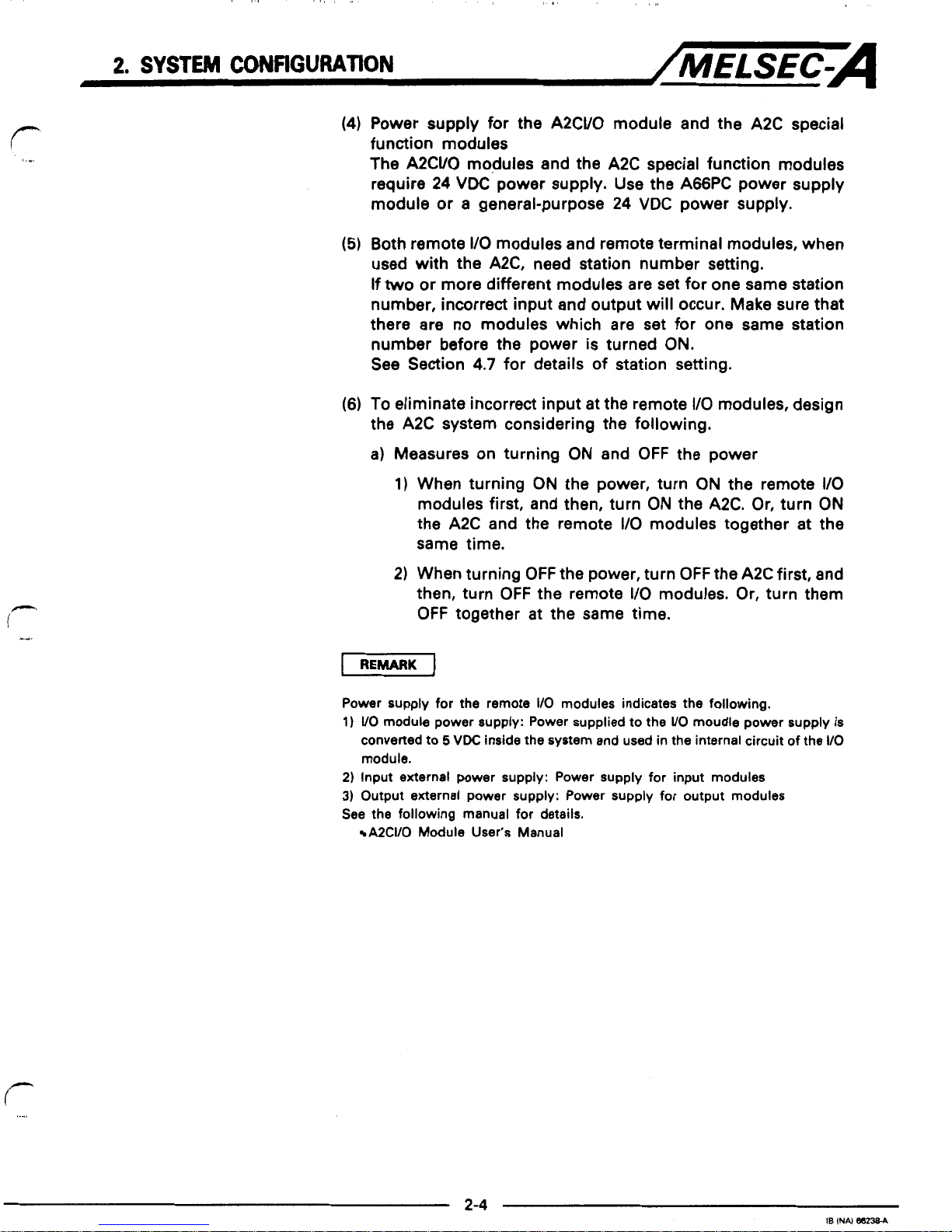
1)
Cause for incorrect input due to momentary power
failure
The
VO
module hardware converts the
I/O
module
power supply
(24
VDC) to
5
VDC
inside the module.
If momentary power failure occurs in the
1/0
module,
incorrect input occurs if
I10
refresh
is
executed within
duration (A) shown below because: (Time from occurrence of external power supply
OFF
to turning
OFF
of
internal 5VDC)
>
(ON
to
OFF
response time of input
module).
External supply
24
VDC
(for
WO
module power supply and input
external power supply)
Inside
5
VDC
ON
OFF
Input (Xn)
I
1
OFF
1
I
L-4
When the input external power supply
is
turned
off,
input (Xn) turns
off
after the
ON-OFF
response'time
of
the input module.
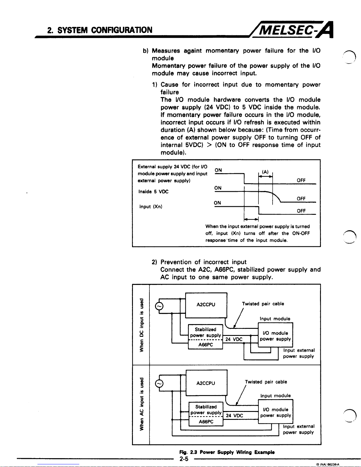
2)
Prevention of incorrect input
Connect the A2C, A66PC, stabilized power supply and
AC input to one same power supply.
I
I
I
I
Input module
WO
modute
+
,
Stabilized
power supply
l..-_______l.
24
VDC
power supply
A66PC
L
--
4--
-
1
Input external
power supply
A2CCPU Twisted pair
cable
Input module
i
I
I
-\
rl
I
I
Fig.
2.3
Pow
Supply
Wiring
Exmk
2-5
IB
(NAI
66238-A
2.
SYSTEM
CONHGURATION
/MELSEC-A
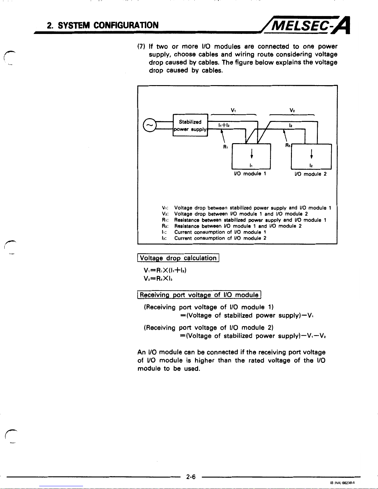
(7)
If
two
or more
I/O
modules are connected to one power
supply, choose cables and wiring route considering voltage
drop caused by cables. The figure below explains the voltage
drop caused by cables.
v1
vz
+
Stabilized
-
h
Rz
I
i
I1
I2
UO
module
1
VO
module
2
V1: Voltage drop between stabilized power supply and
VO
module
1
VZ:
Voltage drop between
I/O
module
1
and
I10
module
2
RI:
Resistance between stabilized
power
supply and
UO
module
1
Rz:
Resistance between
UO
module 1 and
VO
module
2
11:
Current consumption
of
VO
module
1
12:
Current consumption
of
VO
module
2
1
Voltage drop calculation
J
V,=R1X(11+12)
Vz=RzXIz
I
Receiving
port
voltage
of
I/O
module
I
(Receiving
port
voltage
of
I10
module
1)
(Receiving port voltage
of
VO
module
2)
=(Voltage
of
stabilized power supply)-Vl
=(Voltage
of
stabilized power supply)-V1-V2
An
I/O
module can be connected
if
the receiving port voltage
of
VO
module is higher than the rated voltage
of
the
I/O
module to be used.
2.
SYSTEM
CONFtGURATlON
/MELSEC-A
2.3
Systm
Equipment
tq
-
-'
I
In this
section,
the
VO
modules and peripheral devices which can
be used with the A2C are listed.
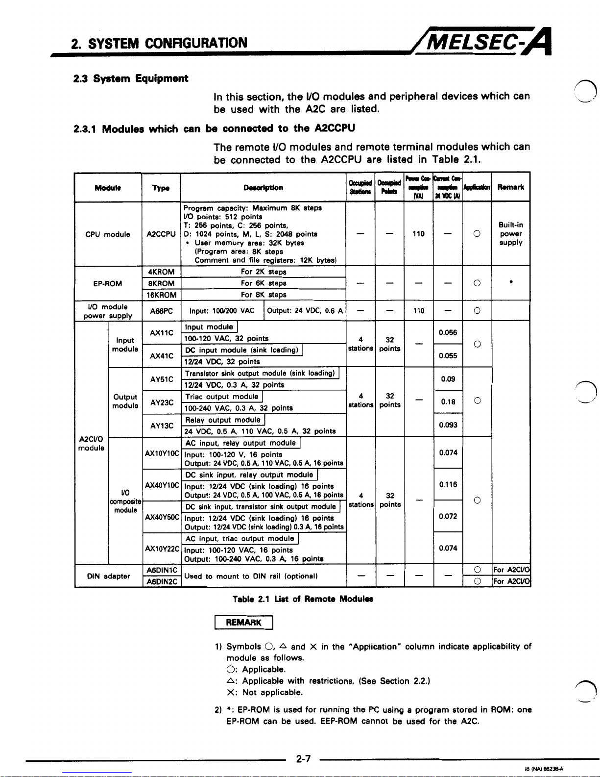
2.3.1
Modules
which
can
be
connected
to the
A2CCPU
The remote
I/O
modules and remote terminal modules which can
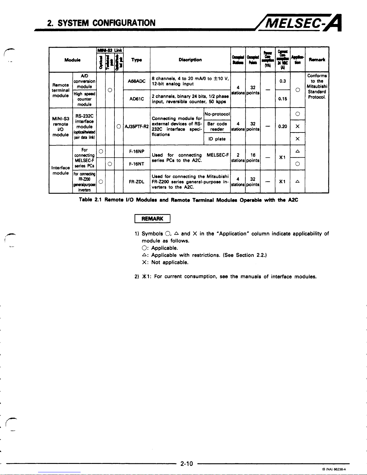
be connected to the A2CCPU are listed in Table 2.1.
Typ.
I
Program capacity: Maximum
8K
steps
VO
points:
512
points
T:
256
points,
C: 256
points,
D:
1024
points,
M,
L,
S:
2048
points
User memory area:
32K
bytes
-
(Program area:
8K
steps
Comment and
file
registers:
12K
bytes)
For
2K
steps
-lo
CPU module
A2CCPU
4KROM
i
EP-ROM
-
-
110
8KROM
16KROM
For
6K
steps
For
8K
steps
-
A66PC
-
Output:
24
VDC,
0.6 A
Input:
1W200 VAC
1
VO
module
UPPlY
Input
module
power
UCVO
nodule
c
32
points
32
points
I
Transistor sink outmt module (sink loadimr)
I
I
I
12/24
VDC.
0.3
A. 32
ooints
I
output
module
vo
ompositc
module
AY23C
station!
AY13C
rl
0.093
I
AC
input,
relay
output module
0.074
0.1 16
-
0.072
-
0.074
32
points
0
n
-.
I
bd
I
Output:
100-240 VAC,
0.3
A,
16
points
-
I+
or
AXVl
'or
A2Cvl
-
A6DINlC
A6MN2C
Used
to
mount to
DIN
rail (optional)
-
DIN
adapter
Table
2.1
List
of
Remote
Maduks
1)
Symbols
0,
A
and X in the "Application" column indicate applicability
of
module as
follows.
0:
Applicable.
A:
Applicable with restrictions. (See Section
2.2.)
X:
Not applicable.
2)
*:
EP-ROM is used
for
running the
PC
using a program stored in
ROM;
one
EP-ROM can be used. EEP-ROM cannot
be
used
for
the
A2C.
2.
SYSTEM
CONFIGURATION
/MELSEC-A
AJ35PJ-8A
AC
input module
I
1W120
VAC. 8 Doints
DC
input module (sink loading)
1
AJ35PJ-8D I 12/24
VDC. 8 mints
0.04
-
0.13
-
0.08
AJ35PJ-8R
Contact output module
]
24
VDC,
2
A,
240
VAC, 2 A. 8 points
Out-of-
panel
type
A
AJ35PJ-8T2
Tramistor
output
module
(rink loading) 1 station
12/24
VDC,
0.5 Nwint, 8 wints
0.03
A135PJ8T3
Tramistor
output
module
isink
loading)
I
12/24
VDC.
2 NDoint. 8 Doints
0.065
-
0.065
-
0.08
Triac output module
AJ35PJ-8Sl
AJ35TJ-8A
AC
input module
I
100-120
VAC, 8 points
0.05
AJ35TJ-8D
DC
input module (sink loading)
I
12/24
VDC. 8 Doints
I
0.05
AJ35TJ8R
1-I
Contact output module
I
24
VDC.
2
A.
240
VAC. 2 A. 8 ooints
0.13
-
0.09
-
0.03
AJ35TJ-8Tl
Transistor output
module
(rink
loading)
I
12/24
VDC,
0.1
&point, 8 points 1
Out-of-
panel
type
A
-
Tramistor Output
module
(sink
loading) r Station
12/24
VDC,
0.5 Npoint, 8 points
AJ35TJ-8T2
AJ35TJ-8T3
Transistor output
module
(sink loading)
I
12/24
VDC,
2 Npoint, 8 points
0.065
AJ35TJ-ESl
1-I
Triac output module
100/240
VAC.
0.6
NDoint. 8 Doints
AJ35TJ-ES2
1-I
Triac output module
1W240
VAC. 2 Nooint. 8 mints
0.09
-
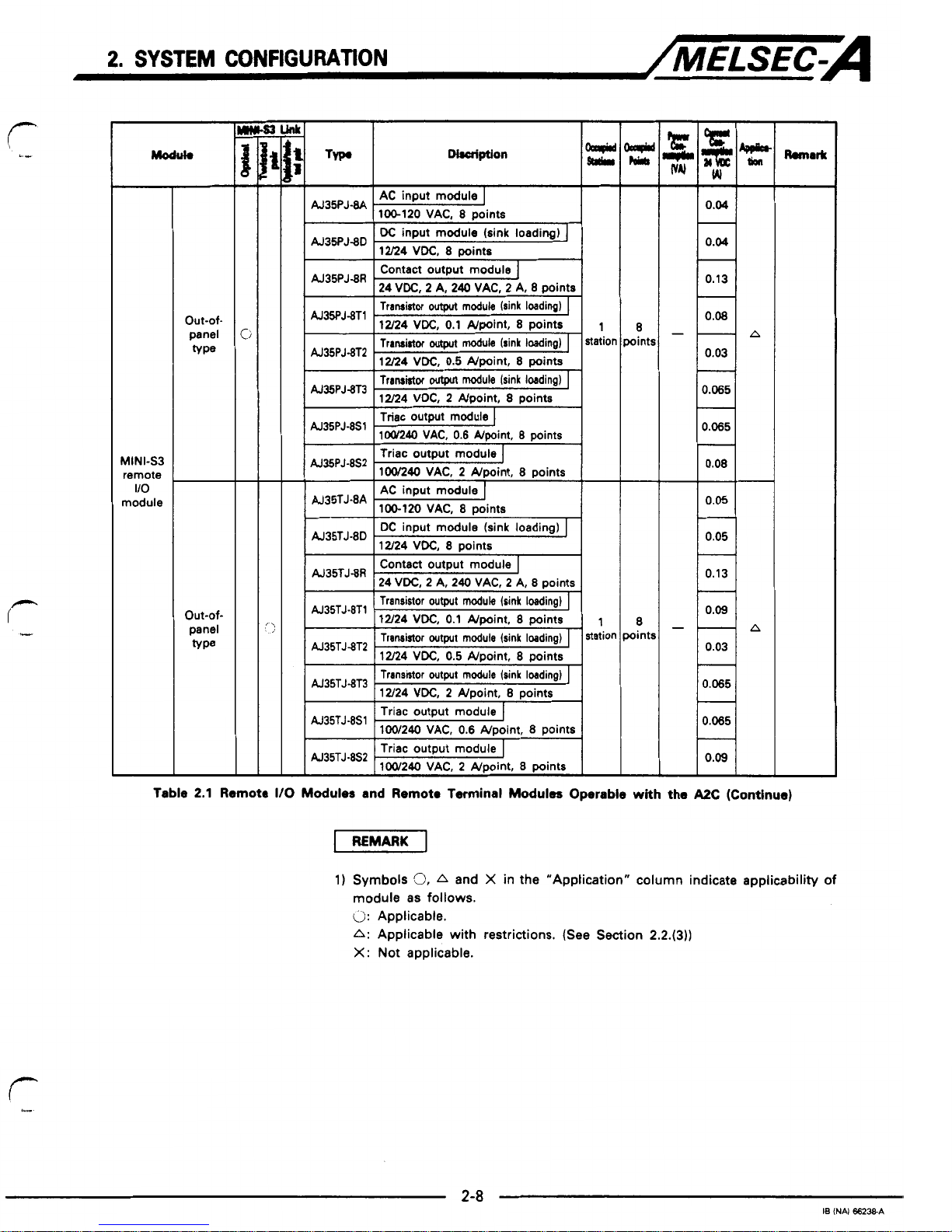
Table
2.1
Remote
I/O
Modules
and Remote Terminal
Modules
Operable
with
the
A2C
(Continue)
1)
Symbols
‘3,
A
and X in the “Apptication”
column
indicate applicability
of
module
as
follows.
0:
Applicable.
A:
Applicable with restrictions. (See Section
2.2.(3))
X:
Not applicable.
2-8
18
(NAI
6623EA
2.
SYSTEM
CONffiURATlON
/MELSEC-A
Modub
-
MINI-S3
remote
uo
module
Compact
wpe
Data
link
module
DC
input module Cink loading)
1
ICJ36m-3201
12/24
VDC.
32
mints
M35PTF-24R
Contact output module]
24 VDC, 2
A,
240 VAC, 2 A, 24
points
At35pTF-24S
AJ35PTF-241
Triac output module
I
10M40 VAC, 0.6
Npoint,
24
points
Tnnrirtor
outpn
mobb
kink
WqJ
I
12/24 VDC, 0.5
mint,
24
points
AC
input contact output module
I
/~m-~IInwt:
100-120 V. 16
wints
I
IOutput:24VDC,2A240VAC,2412points
AC
input, triac output module
I
Output:
lOG240VAC.
0.8rVpoint
12
points
A1rn-W
Input:
100-120 VAC, 16
points
r
T
input, contact output module
I
lM~~-28DRI
Input:
Sink lordina,
12/24
VDC,
18
points
I
I
Output:
24
VDC, 2
k
240
VAC,
2
A
12
points
DC
input, triac output module
lM~~-~sl
Input: Sink Wng,
12/24 VDC,
16
poi
Ats
I
1
Outout:
104.240
Vk
0.6
Writ
12
wints
I
...
3
AC
input, contact output module
I
Input:
100-120 V, 32
point8
Output:
24 VDC,
2
A,
240 VAC, 2 A, 24
points
AC
input, triac output module
]
Input:
100-120 VAC, 32
points
output:
10~210
VAC,
a6
point,
24
points
DC
input, contact output module
~:24VDC,24240VAC,2424poit?ts
Input: Sink loading,
12/24
VDC,
32
points
DC
input, triac wtput module
Input:
Sink
loading,
12/24 VDC,
32
points
Outout:
1W240 VAC.
0.8
#dnt
24
wints
L
r.r
Ovtan:122421VDC(dntloldim)05W24W
AJ72PT35
Used
when the building block
type
UO
module is used
as
the remote
UO
module.
Max.
of
UO
modules:
8
Max.
UO
points:
128
Occupied stations:
4,
8,
12, 16
Iselectable)
w
m
-
4
tatiir
8
tatim
See
left.
W
0.1 1
-
0.11
-
0.12
-
0.20
-
0.13
-
0.12
-
0.14
-
0.12
-
P
0.15
-
0.1 1
-
0.15
-
0.23
-
0.1
6
-
0.23
-
0.16
-
A
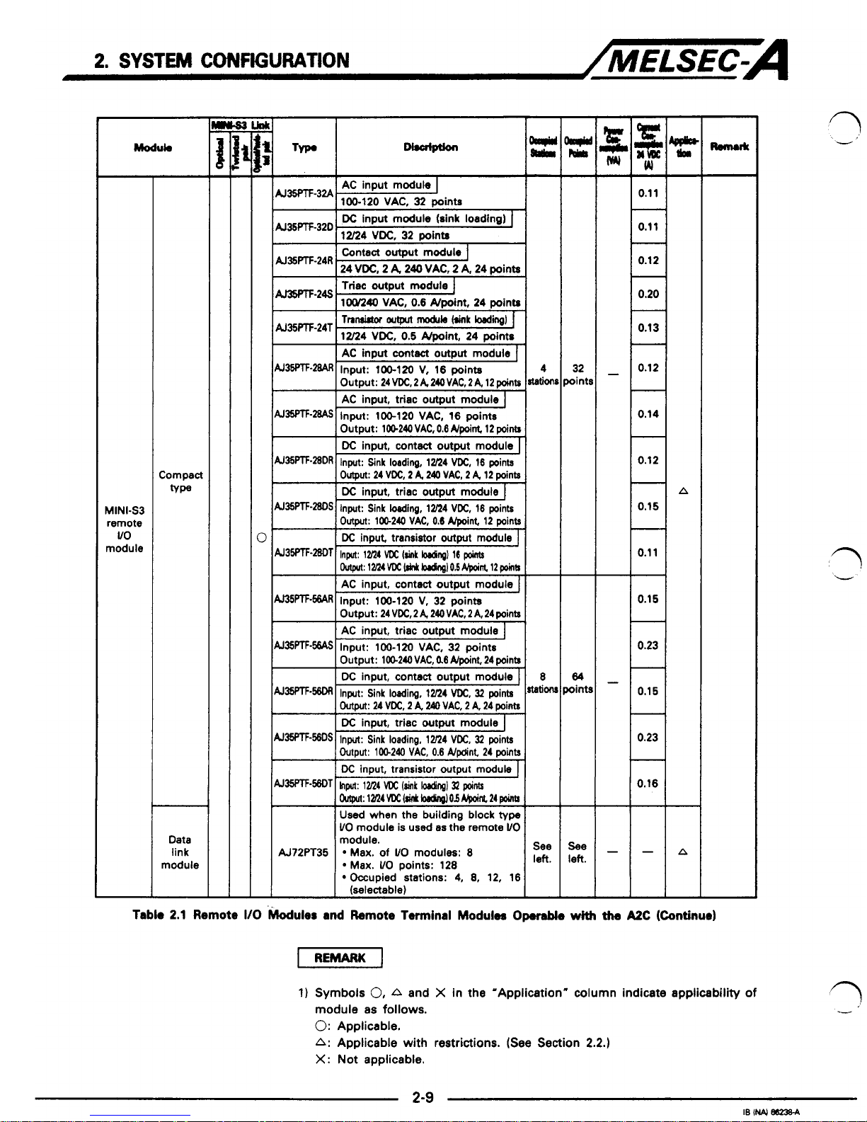
Tabk
2.1
Remote
I10
.koduler
and Remote Terminal
Modulea
Operable
with
the
A2C
(Continue)
1)
Symbols
0,
A
and X in the "Application"
column
indicate applicability
of
module as follows.
0:
Applicable.
A:
Applicable with restrictions. (See Section
2.2.)
X:
Not applicable.
f“
I..
2.
SYSTEM
CONFIGURATION
/MELSEC.A
conversion
terminal
module
counter
Interface
module
1
0
AJWF-R2
F-
16NP
8
channels,
4
to
20
mA/O to
i10
V,
12-bit analog input
2
channels, binary
24
bits, 1/2
phase
input, reversible counter,
50
kpp
0.3
4
32
--
r”
points
0
0.15
No-protocol
0
0.20
x
ID
plate
X
Connecting module for
-
external devices
of
RS-
Bar code
4
32
-
23X
interface speci- reader
rtstions
points
fications
-
Used
for connecting
MELSEC-F 2
16
-
*l
-
A
series
PCs
to
the
A2C.
stations points
0
Used
for connecting the Mitsubishi
verters to the
AZC.
FR-2200
series
general-purpose in-
Conforms
to the
Mitwbishi
Standard
Protocol.
Table
2.1
Remote
I10
Modules
and
Remote
Twminal
Modules
Op.r.bk
with
the
AzC
1)
Symbols
0,
A
and X in the “Application“ column indicate applicability
of
module as
follows.
0:
Applicable.
A:
Applicable with restrictions. (See Section
2.2.)
X:
Not applicable.
2)
gl:
For
current consumption, see the manuals
of
interface modules.
2.
SYSTEM
CONFIGURATION
/MELSEC-A
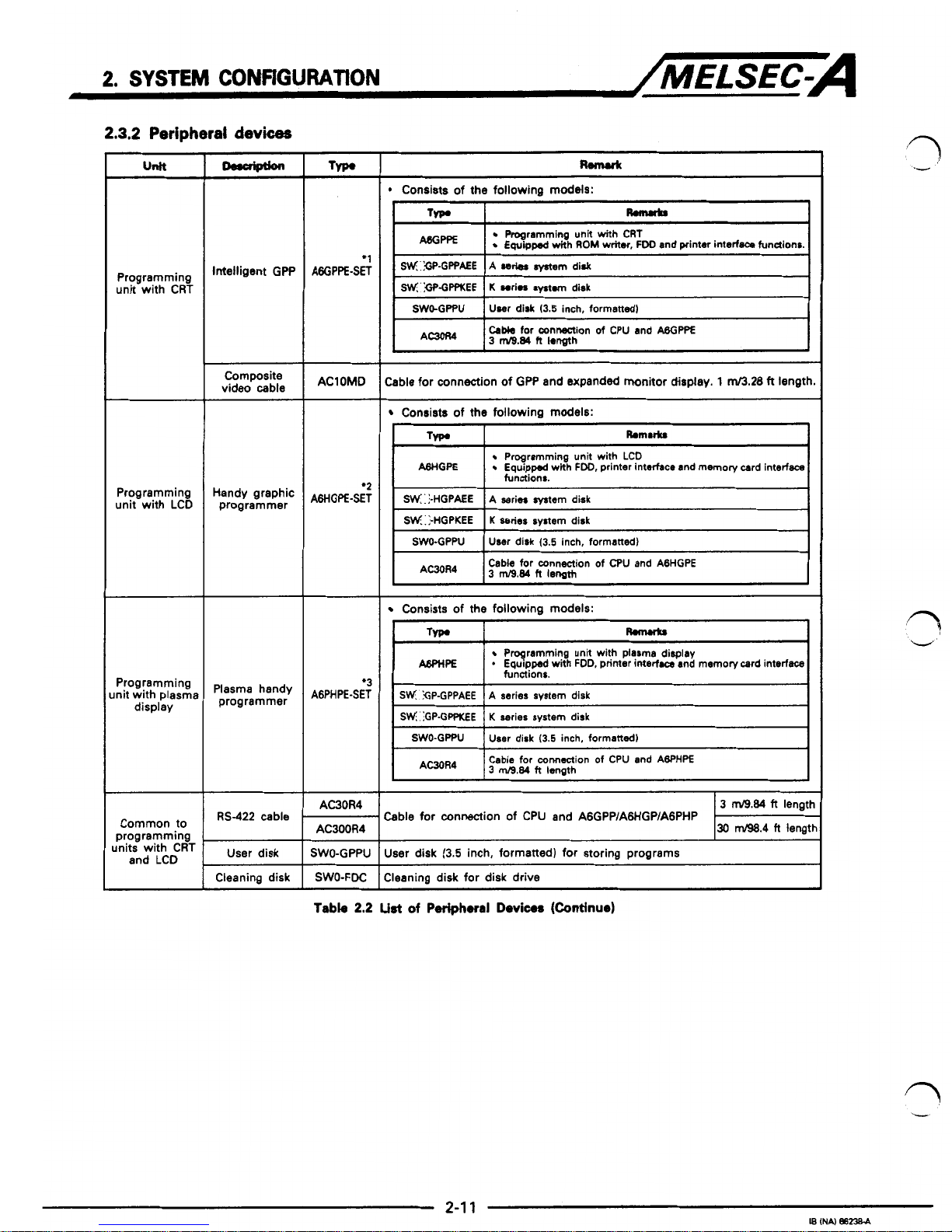
2.3.2
Peripheral
devices
T
Programming
unit with CRT
Intelligent GPP
I
video
cable
Composite
unit
with LCD
Handy graphic Programming
programmer
lnit
with plasma
Programming
p$~~~Bmned,y
display
Common to
1
RS-422
cable
programming
I
Cleaning disk
A6GPPE-SET
*1
AClOMD
AGHGPE-SET
*2
AGPHPE-SET
*3
AC30R4
AC300R4
SWO-GPPU
SWO-FDC
Wmuk
*
Consists of the following models:
I
TW
R.mr(rr
I
I
I
Equipped
with
ROM
writer,
FW
and printer intarface fundions.
Programming unit with CRT
SVII;':GP.GPPKEE
K
swim
systun
disk
SWO-GPPU
User disk
(3.5
inch, formatteddl
I
A-
I
Cabk
for mnne3ion
of
CPU and
ABGPPE
3
m10.84
h
Iongth
:able
for connection of GPP and expanded monitor display.
1
M.28
ft
length.
Consists
of
the
following
models:
Tvpr
Rnnulu
PSHGPE
Equipped with
FDD,
printer interface and memory card interface
Programming unit with LCD
functions.
SW:l-HGPAEE
K
wries
system disk
SN::-HGPKEE
A series system disk
SWO-GPPU User disk
(3.5
inch, formatted)
I
AWR4
I
Cable
for connection of CPU and ABHGPE
3
d.84
h
lenath
I
I
I
Consists of
the
following models:
Typ.
R.mw(u
ABpnPE
*
Equippad with FDD, printer interfaca and mamory card interface
Programming unit with
plasma
display
functions.
I
SN
SP-GPPAEE
I
A series system disk
I
I
SN
:GP-GPPK€E I K
series system disk
I
SWO-GPPU
User disk
(3.5
inch, formatted)
~~ ~~
AC30R4
Cable for connection of CPU and ABPHPE
3
mB.84
ft
length
Cable
for connection of CPU and AGGPP/AGHGP/AGPHP
30
MB.4
R
lengtt
User disk
(3.5
inch, formatted)
for
storing programs
Cleaning disk for disk drive
-
1
d
3
n
d
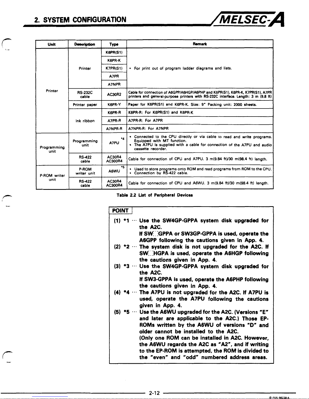
Table
2.2
List
of
Pedphwal
Devices
(Continue)
2.
SYSTEM
CONFIGURATION
/MELSEC-A
Unlt
Printer
Programming
unit
P-ROM writer
unit
o..aiptbn
R.mu(t
TYP.
KGPR(S1)
KGPR-K
Printer
For print out of program ladder diagrams and lists.
K7PR(S1)
A7PR
A7NPR
RS-232C
Cable for connection of AGGP?/AWGP/AGPHP and KGPR(Sl), KGPR-K. K7PR(S1), A7PF
AC30R2
cable
printen and general-purpose printers
with
RS-232C interfsce. Length: 3
rn
(9.8
fl
Printer paper
I
KWR-Y
I
Paper for KGPR(S1) and KGPR-K. Size: 9' Packing unit: sheets.
I
KGWI-R I KWR-R: For KGPR(S1) and K6PR-K
Ink ribbon
I-R
IA7PR-R: For A7PR
A7NPR-R
A7NPR-R: For A7NPR
~~~ ~ ~
Connected
to
the CPU directly or via cable to read and
write
programs
unit
The A7PU is supplied with a cable for connection of the A7PU and audic
A7PU
Programming
Equipped with
MT
function.
cassette recorder.
RS422
cable
1
ft$:$4
I
Cable for connection of CPU and A7PU. 3 m(9.84
RV30
m(98.4
R)
length.
P-ROM
Used to store pro rams onto
ROM
and read programs from
ROM
to the CPU
*5
writer unit
Connection by R8-422 cable.
RS422
cable
LEY4
Cable for connection of CPU and AGWU. 3 rn(9.84
ft)/30
m(98.4
ft)
length.
Tabk
2.2
List
of Peripheral
Devices
POINT
I
(1)
*l
Use the SW4GP-GPPA system disk upgraded for
the
A2C.
tf
SW:lGPPA
or
SW3GP-GPPA is used, operate the
AgGPP following the cautions given
in
App.
4.
(2)
*2
e-.
The system disk is not upgraded for the
A2C.
If
SW[ :IHGPA is used, operate the AGHGP following
the cautions given
in
App.
4.
(3) *3 Use the SW4GP-GPPA system disk upgraded for
the
A2C.
If
SW3-GPPA is used, operate the AGPHP following
the cautions given
in
App.
4.
(4)
*4
The A7PU
is
not upgraded for the
A2C.
If
A7PU
is
used, operate the A7PU following the cautions
given
in
App.
4.
(5)
*5
Use the AGWU upgraded for the
A2C.
(Versions 'E"
and later are applicable to the
A2C.)
Those
EP-
ROMs
written by the AGWU of versions
"D"
and
older cannot be installed to the
A2C.
(Only one
ROM
can be installed
in
A2C.
However,
the AGWU regards the
A2C
as
"A2",
and
if
writing
to the
EP-ROM
is
attempted, the
ROM
is divided to
the "even" and "odd" numbered address areas.
3.
GENERAL
smmmoNs
/MELSEC~A
3.
GENERAL
SPECIFCATKINS
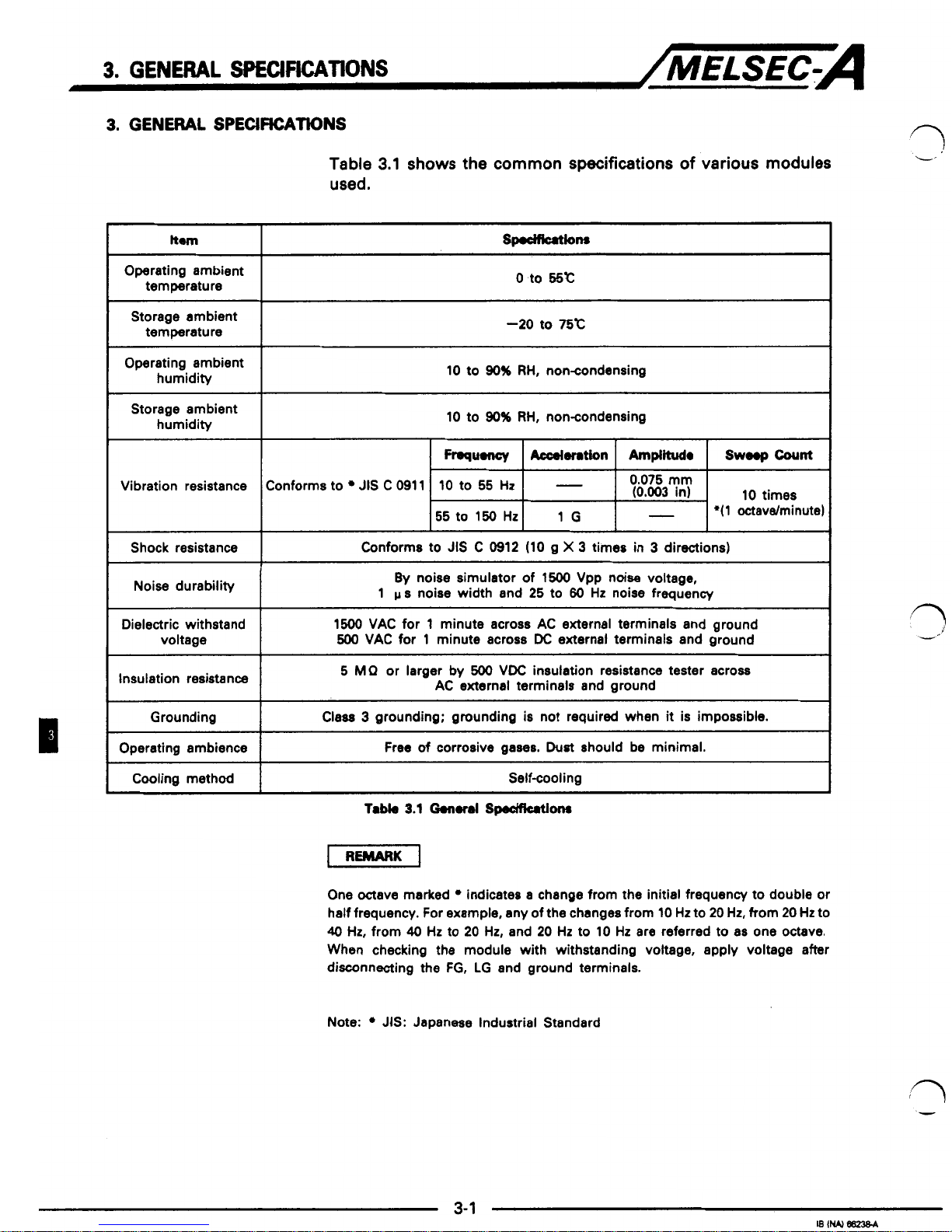
Table
3.1
shows the
common
specifications
of
various
modules
used.
ttm
Operating ambient
temperature
Storage ambient
temperature
Operating ambient
humidity
Storage ambient
humidity
Vibration resistance
Shock resistance
Noise durability
Dielectric withstand
voltage
Insulation resistance
~ ~~~
Grounding
Operating ambience
Cooling method
~ ~~~~
0
to
65c
-20
to
75c
10
to
90%
RH,
noncondensing
10 to
90%
RH,
noncondensing
Conforms to
JIS
C
0911
10
to
55
Hz
-
0.075
mm
(0.003
in) 10 times
55
to 150
HZ
1G
-
*(l
octavdminute)
1
Conforms to
JIS
C
0912
(10
g
X
3
times in 3 directions)
1
By
noise simulator
of
1500
Vpp noise voltage,
1
p
s
noise width and
25
to
60
Hz
noise frequency
1500 VAC for
1
minute across AC external terminals and ground
500
VAC for 1 minute across
DC
external terminals and ground
5
MP
or larger by
500
VDC insulation resistance tester across
AC external terminals and ground
Class
3
grounding; grounding
is
not required when it
is
impossible.
Free of corrosive gases.
Dust
should
be
minimal.
Self-cooling
Tabb
3.1
0.n.t.l
Smom
One octave marked indicates a change from the initial frequency to double or
half frequency. For example, any of the changes from
10
Hz
to 20
Hz,
from
20
Hz
to
40
Hz,
from
40
Hz
to
20 Hz,
and 20
Hz
to 10
Hz
are referred to as one octave.
When checking the module with withstanding voltage, apply voltage after
disconnecting the
FG,
LG and ground terminals.
d
c
i
1
-1
c
I
1
1
I
Y
Note: JIS: Japanese Industrial Standard
-
/I
’P
n
,
,,
r-
I-
4.
A2CcPU
/MELSEC-A
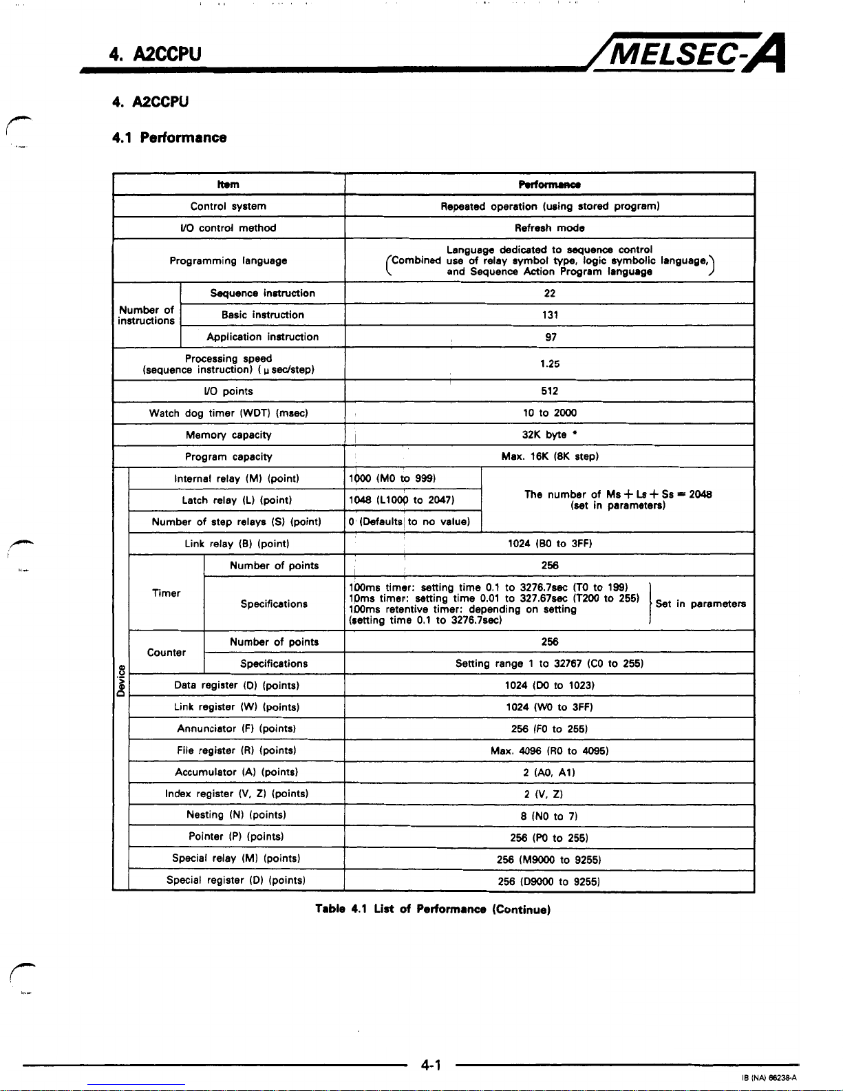
4.
A2ccw
4.1
Performance
Repeated operation (using stored program)
~~
VO
contrd method
Refresh
mode
Languaw dedicated to
aequenoe
control
and Sequence Action Program Ianguuge
Programming language
(Combined use
of
relay
symbol
type,
logic symbolic language,
Sequence instruction
131
Basic instruction
22
97
Application instruction
instructions
Number
of
r
Processing speed
(sequence instruction)
(
p
sedstep)
I
1.25
Program capacity
I
Max.
16K
(8K
step)
Latch relay (L) (point)
1048
(Llw
to
2047)
The
number
of
Ms
i-
Ls
i-
Ss
=
2048
(set in parameters)
Number of step relays
(SI
(point)
0'
(Defaults~ to
MI
value)
I
Link relay
(B)
(point)
1024
(BO
to
3FF)
Number
of
points
256
Timer
lOOms
timir: setting time
0.1
to
3276.7% (TO
to
199)
lmms
retentive timer: depending on setting
(retting time
0.1
to
3276.7~~)
Specifications
1Dms
timer: setting time
0.01
to
327.67~ (T2W
to
255)
Number
of
points
256
Counter
Specifications Setting range
1
to
32767
(CO to
255)
Data register (D) (points)
1024
(W
to
1023)
Link reaister
(W)
(mints)
1024
(WO
to
3FF)
Annunciator
(F)
(points)
I
256
(FO
to
255)
File register
(R)
(points)
I
Max.
4096
(RO
to
4095)
Accumulator
(A)
(points)
I
2
(AO,
AI)
Index register
(V,
2)
(points)
2
(V.
2)
Nesting (N) (points)
8
(NO to
7)
Pointer
(P)
(points)
256
(m
to
2551
Special relay
(MI
(points)
256
(M9000
to
9255)
Special register (Dl (points)
256
(D9OOO to
9255)
Table
4.1
List
of
Performance (Continue)

P
4.
A2CcPU
/MELSEC-A
I
Item
I
Rrlomuna
I
~~ ~
Comment
(points)
Max.
l&
(specify
in' batches of
64
points)
*'
watch
dog
error monitor (watdr
dog
timer
200msl
battery
error detection,
etc.
Selfdiegnortic function8
Memory
error detection,
CPU
error
detection,
VO
error
detection,
Operation mode at
the
time
of
error
STOPKONTINUE
I
STOP
-.
RUN
Output
mode
Output
data
at time
of
STOP
mstoreddata
output
after operetion execution
I
I
Weight
kg
(Ib)
I
1.1 (2.41)
I
Input power
100
to 120
VACI200 to 240
VAC
T!g
(85
to
132 VAU170
to
264
VAC)
Input frequency
110 VA or
less
Maximum inout emrent mwar mwer
5(y80
Hz
f3
Hz
A2C internal
-utW.'V
I
Inrush current
I
20
APlZO AP or
less
I
I
I
1
I
I
Efficiency
I
65%
or over
I
I
Allowable momentary
power
failure
20
msec
or
leu
Tabk
4.1
Lkt
of
Pwfonnuta
*:
Total memory capacity for parameters, T/C
set
values, program capacity,
file
registers, comment points, sampling trace and
status
latch.
See
Section
4.4
for
memory
capacity calculation.
*1:
With
GPPIPHPRIGP,
comments up to
4032
points can
be
used. Note that the
maximum of storage capacity of
the
A2C
is
1600
points.
i/?
-
--
'1
Y
i
n
m
I
J
 Loading...