

Page 1
AMITSUBISHI
PROGRAMMABLE CONTROLLERS
Page 2

I
Page 3
CONTENTS~
Foreword
Chapter
Chapter
1:
What
How
What Do I Choose
Where
Is
It Difficult
What Can
2:
Central processing unit (CPU Module)
CPU Base Units
Extension Base Units
Power supply modules ............................................................................................ 12
Input modules ......................................................................................................... 13
Output modules
.......................................................................................................
Overview
is
the AIS
Does It Work
&
How
I
AIS
Model No
Model No . AlS32B
Model
Model
Model
Model
Model
Model
Model No . AlS65B
Model
Model
Model
Model
Model
Model No . AlSX20 ..................................................................................... 13
Model
Model
Model
Model
Model
Model
Model
Model
Model
Model
Model
Model
Model
Model
Model
Model
Model
Model
Model
Model
Model
Model
Model
Model
Model
of
the
AIS
PLC .......................................................... 2
?
...................................................................................................
?
................................................................................................
?
................................................................................................
Do
I
Install
It
?
..................................................................................
To
Program ?
Use It For
Module Descriptions
......................................................................................
?
..........................................................................................
.........................................................
....................................................................
.
AlSCPU,
AISCPU-S1
..............................................................
......................................................................................................
.....................................................................................
No . AlS33B
No . AlS35B
No
. AlS38B ..................................................................................... 9
.....................................................................................
.....................................................................................
..............................................................................................
No
. AlS52B
No . AlS55B
No
. AlS58B
.....................................................................................
.....................................................................................
.....................................................................................
.....................................................................................
No
. AlS68B
No
.
AlSGIP
No
.
AlS62P
No
. AlS63P
No
.
AlSX10 ..................................................................................... 13
No
. AlSX30
No
. AlSX40 ..................................................................................... 14
No
. AlSX40-S1
No . AlSX40-SZ
No
.
AlSX4l
No
.
AlSX41-SZ
No
. AlSX42
No
. AISX42-SZ
No
.
AlSX71
No
. AlSX80
No
. AlSX80-SI ................................................................................ 15
No
.
AlSX80-SZ
No
. AlSX81
No
.
AlSX81-SZ
.....................................................................................
.....................................................................................
.....................................................................................
.....................................................................................
.....................................................................................
................................................................................
................................................................................
.....................................................................................
................................................................................
.....................................................................................
................................................................................
.....................................................................................
.....................................................................................
................................................................................
.....................................................................................
................................................................................
......................................................................................................
No
.
AlSY10
No
.
AlSY18A ................................................................................... 18
No
. AlSY22
No . AlSY28A
No
. AlSY40
No . AlSY41
No
.
AlSY42
No
. AISYSO
No . AISY6O
No
. A1 SY6OE ................................................................................... 19
No
. AlSY68A ................................................................................... 19
.....................................................................................
.....................................................................................
...................................................................................
.....................................................................................
.....................................................................................
.....................................................................................
.....................................................................................
.....................................................................................
i
2
2
3
3
4
4
5
5
5
8
8
8
9
10
10
10
11
11
11
12
12
12
14
14
14
14
14
15
15
15
15
15
16
16
17
17
18
18
18
18
19
19
19
i
Page 4
‘CONTENTS
..
Model No . AlSY71
No
.
Model
Model
Special function modules ........................................................................................ 21
Model
Model No
Model
Model
Model
Model
Model No
Model
Model
Model
Model No . AlSD71-S2
Model
Model
Model
Model
Model
Model
Model
Model No
Model No
Memory modules
Model
Model No . A1 SMCA-8KE ............................................................................ 27
Model
Extension cables ..................................................................................................... 28
Model
Model
Model
Model No
Model
Terminal block units and cables
Model No
Model
Model
Model
Model No
Model
Model
Model
Model
Model
Model
Model No
Model
Model
Model
Model No
Model No
Model
AlSY80
No
. AlSY81
No
. AlS64AD
. AlS62DA
No
.
AlSJ71C24-R2 .......................................................................... 22
No . AlSJ71C24-R4 .......................................................................... 22
No
.
AlSJ71C24-PRF
No
. AlSD61
. AlS161 ...................................................................................... 23
No
.
AlSJ71T21B ............................................................................. 23
No
. AlSJ71PT32-S3
No
. AlSD70 ..................................................................................... 24
No
. AlSP6O ..................................................................................... 24
No.
AlSH42
No . AlS42X
No
.
AlS42Y
No
.
AlSG6O
No
. AlSG62
No
. AlS62RD3 ................................................................................ 25
. AlS62RD4
.
AlST60
....................................................................................................
No
. AI SMCA-2KE
No
.
A1 SMCA-8KP
No
.
AlSCOlB .................................................................................. 28
No
. AlSC03B
No
. AlSC12B
.
AlSC30B
No . AlSCOSNB
.
A6TBXY36
No . A6TBXY54
No
.
A6TBX70
No . A6TBX36-E
.
A6TBY36-E
No
. A6TBX54-E
No
. A6TBY54-E
No
. A6TBX70-E
No
.
ACOSTB
No
. AClOTB
No
. AC20TB
. AC30TB
No
.
ACSOTB .................................................................................... 31
No
.
ACOSTB-E
No . AClOTB-E ................................................................................. 31
.
AC20TB-E ................................................................................. 32
.
AC30TB-E
No
. ACSOTB-E
.....................................................................................
.....................................................................................
.....................................................................................
..................................................................................
..................................................................................
.......................................................................
.....................................................................................
........................................................................
...............................................................................
.....................................................................................
.....................................................................................
.....................................................................................
....................................................................................
....................................................................................
................................................................................
.....................................................................................
............................................................................
............................................................................
..................................................................................
..................................................................................
..................................................................................
................................................................................
..............................................................................
................................................................................
................................................................................
...................................................................................
...............................................................................
...............................................................................
...............................................................................
...............................................................................
...............................................................................
....................................................................................
....................................................................................
....................................................................................
....................................................................................
.................................................................................
.................................................................................
.................................................................................
20
20
20
21
22
22
23
23
24
24
24
25
25
25
25
26
27
27
27
28
28
28
28
29
29
29
30
30
30
30
30
30
30
31
31
31
31
32
32
Chapter
System selection
3:
System Selection and Configuration .......................................
.....................................................................................................
Step 1
:
Step 2: Output module selection
Input module selection ................................................................... 34
.................................................................
ii
33
33
35
Page 5
Step 3: Special function module selection .................................................. 36
Step 4: Power supply module selection
Step
5:
System configuration
S
System Examples
AI
System Example
System Example 2
System Example 3
System Example
Base unit selection
CONTENTS~
......................................................
..............................................................................................
...........................................................................................
1
4
.........................................................................
.....................................................................................
.....................................................................................
.....................................................................................
.....................................................................................
37
38
39
40
40
41
42
43
Chapter
4:
Installation
Installation environment
Base unit mounting instructions
Mounting the base units on DIN rail
Installation and removal of AIS modules
Installation and removal of dustproof cover
..................................................................................
..........................................................................................
...............................................................................
.........................................................................
................................................................
............................................................. 51
Chapter 5: Wiring .........................................................................................
Wiring instructions for the power supply module
Wiring
Grounding ............................................................................................................... 56
Chapter
Description
Programming language
Numeric value and character representation
Instructions
of
I/O
equipment
6:
Programming
of
internal devices ................................................................................ 58
Inputs X
Outputs Y
Auxiliary relays MI L.
Link relays
Annunciators F
T
Timer
Counter C
Interrupt counters C
Data register D
Link register
File registers R
Accumulator A
Index registers
Nesting N
Pointer
Interrupt pointer
Special relays M
Special registers D
P
..........................................................................................
.............................................................................
......................................................................................................
...................................................................................................
B
...............................................................................................
...................................................................................................... 60
...................................................................................................
W
...................................................................................................
....................................................................................................
S
...............................................................................
...........................................................................................
....................................................................................
...........................................................................................
...........................................................................................
...........................................................................................
............................................................................................
2,
V .................................................................................... 64
I
........................................................................................
.........................................................................................
.....................................................................................
...........................................................................................
Binary (BIN)
Binary coded decimal (BCD)
Hexadecimal (HEX)
ASCI
I
............................................................................................... 74
......................................................................
.................................................................................... 75
......................................................................................................... 76
.............................................................................................................
Explanation of instruction lists
List of sequence instructions
List of basic instructions
List of application instructions ..................................................................... 90
Sequence instruction description
Contact instructionsoperation start, series connection,
parallel connection (LD, LDI, AND, ANI, OR, ORI)
Connection instructionsLadder block series connection and
parallel connection (ANB, ORB)
....................................................................
.......................................................................
.............................................................................
.....................................................
...........................................................
................................................................
.........................
.....................................................
44
44
45
47
49
52
52
55
57
58
58
59
59
60
61
61
62
62
63
63
65
66
66
67
70
73
74
74
77
78
81
83
97
97
100
...
111
Page 6

CONTENTS
Chapter
Building Management
Milling Machine ....................................................................................................... 135
Welding Robot
Winding Machine
Energy Management of Compressor Station
Operation result push. read. pop (MPS. MRD. MPP)
Output instructionsBit device. timer. counter output
Bit device set. reset (SET. RST) .................................................... 109
Edge-triggered differential output (PLS. PLF)
Bit device output reverse (CHK)
Shift instructions. Bit device shift (SFT. SFTP)
Master control instructions. Master control set. reset (MC.
MCR)
.............................................................................................
Termination instructions
Basic instruction descriptions
Application instruction descriptions ............................................................. 133
7:
AIS Application Examples
Other instructions
Comparison operation instructions
Arithmetic operation instructions
BCD/BIN conversion instructions
Data transfer instructions
...........................................................................
......................................................................
.....................................................
................................................................. 118
................................................. 122
....................................................
...................................................
...............................................................
.......................................................
.............................................................................................
MELSECNETIB data link control system application
Positioning control system application
........................................................
...................................
........................................................................................................
Robot control system application ................................................................ 136
....................................................................................................
Analog control system application
..............................................................
...........................................................
Sequence control system application
.......................................................... 138
......................
(OUT)
.............
.................................
..............................
103
106
111
113
114
116
120
121
125
128
130
134
134
134
135
136
137
137
138
Index .............................................................................................................. 139
Page 7
i
I
Foreword
The
programmable logic controller
covered in this manual include unit selection, system configuration, installation,
programming, and application examples.
It is hoped that after reading this, you will have a good understanding of the
PLC system, and be able to set up and use an AIS PLC system without the need
training
details
appropriate you should refer to the relevant user's or programming manual.
AIS
handy manual
or
the study
of
the
AIS
is
designed as a learning aid for use with the MELSEC
(PLC)
and is aimed at the first time
of
individual manuals. However, please note that not all the
PLC
are contained in this handy manual and therefore where
AIS
user. Topics
AIS
AIS
of
1
Page 8
I
OVERVIEW
I
Chapter 1 :
Overview of the AIS
PLC
1
I
IWhat
lHow
is
the
AIS
?
The Mitsubishi
performance, compact micro modular PLC capable of solving almost all types of
industrial control applications from simple relay replacement,
networking.
Does
It
Work
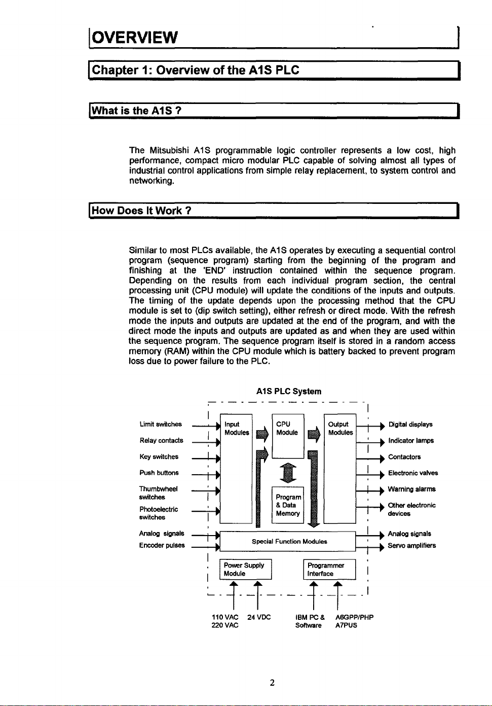
Similar
to
program (sequence program) starting from the beginning of the program and
finishing at the
Depending on the results from each individual program section, the central
processing unit (CPU module) will update the conditions of the inputs and outputs.
The timing of the update depends upon the processing method that the CPU
module is set to (dip switch setting), either refresh or direct mode. With the refresh
mode the inputs and outputs are updated at the end of the program, and with the
direct mode the inputs and outputs are updated as and when they are used within
the sequence program. The sequence program itself is stored in
memory (RAM) within the CPU module which is battery backed to prevent program
loss due to power failure to the PLC.
AIS
programmable logic controller represents a low cost, high
?
most PLCs available, the
'END
instruction contained within the sequence program.
A1S
to system control and
AIS
operates by executing a sequential control
a
random access
PLC
System
I
I
I
Limit
switches
Relay contacts
Key
switches
Push buttons
Thumbwheel
switches
Photoelectric
switches
Analog signals
Encoder
pulses
Input
~
I
,~l
I
L_
s
llOVAC 24VDC IBM
220 VAC Soflware
2
Modules
Programmer
F]i
!X
8
AGGPPIPHP
A7PUS
Digital displays
Indicator lamps
Contactors
Electronic valves
Warning alarm
other
electronic
devices
Servo
amplifiers
Page 9
OVE
RVI
E
w
1
lWhat
(Where
Do
I
Choose
Understandably, when you look at the complete list of different types
output, and special function module available for the AIS, it can seem a difficult
task to choose what you require for your application. But don't worry, the reason for
all the different types of module is
application. All you have
input and output to be used in your application, and select the right type and
number of modules from the list. The only other things to consider then are that you
need a
modules you have selected. Also choose the programming device you want to use
for the creation of your sequence program.
&
How
The AIS
however it can
etc.. is made. Because of its micro modular design it takes up very little space and
can be fixed
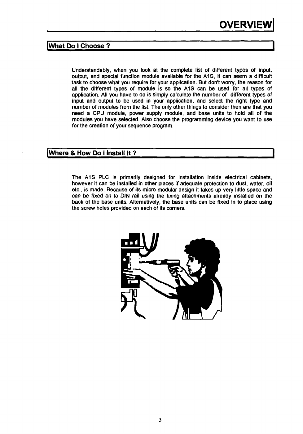
back of the base units. Alternatively, the base units can be fixed in to place using
the screw holes provided on each of its corners.
7
so
to do is simply calculate the number
CPU
module, power supply module, and base units to hold all of the
Do
I
Install It
PLC
is primarily designed for installation inside electrical cabinets,
be
on
to
7
installed in other places if adequate protection to dust, water, oil
DIN
rail using the fixing attachments already installed on the
the AIS can be used for all types of
of
different types of
of
input,
I
I
3
Page 10
..
I
OVERVIEW
11s
It
Difficult
To
Program
7
..
.
....
..
. . . . .
....
.
...
.
-
1
I
Like all things that need programming, the
user to be a little difficult to program. However, the sequence programming
language utilized, is designed to make it as easy as possible for you the user
create your own sequence programs without the need of specialized help. In fact,
after a very short time you can become very proficient at writing programs which
can perform the simple or complicated operations required
needs.
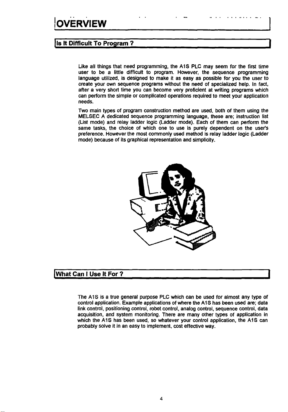
Two main types of program construction method are used, both
MELSEC
(List mode) and relay ladder logic (Ladder mode). Each of them can perform the
same tasks, the choice of which one to use is purely dependent on the user's
preference. However the most commonly used method is relay ladder logic (Ladder
mode) because of its graphical representation and simplicity.
A
dedicated sequence programming language, these are; instruction list
AIS
PLC may seem for the first time
to
meet your application
of them using the
to
[What
Can
I
Use
It
For
7
The
A1S
control application. Example applications of where the
link control, positioning control, robot control, analog control, sequence control, data
acquisition, and system monitoring. There are many other types
which the
probably solve it in an easy
is a true general purpose PLC which can be used for almost any type of
A1S
has been used,
so
whatever your control application, the
to
implement,
cost
4
A1S
effective way.
has been used are; data
of
application in
AIS
1
can
Page 11
I
Chanter
2:
AIS
Module Descrintions
I
h
ICentral processing unit (CPU Module)
I
Model
No.
AISCPU. AISCPUSI
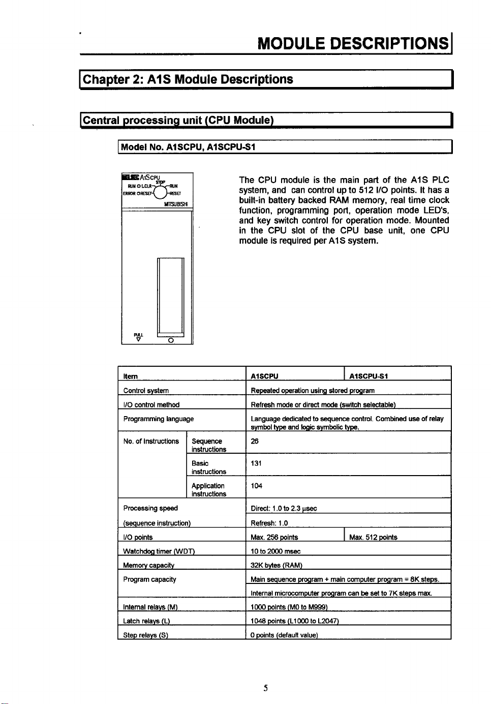
The CPU module is the main part of the
]ERROR
ORM
u-=
UlPjUBlsn
system, and can control up
built-in battery backed
function, programming port, operation mode
and key switch control for operation mode. Mounted
in the CPU slot of the CPU base unit, one CPU
module
r
is
required per
to
512
110
points.
RAM
memory, real time clock
AIS
system.
AIS
It
LEDs,
b
I
I
PLC
has a
Internal relays
Latch relays (L)
Step relays
(S)
(M)
Internal microcomputer
IO00
points
(MO
to
M999)
1048
points (LlO00 to L2047)
0
points
(default
value)
5
program
can
be
set
to
7K
steps
max.
Page 12
1024 points (BO
256
points
to B3FF)
Specifidins
(W)
(R)
(M)
Number of
points
Specifmtions
2)
(1)
power failure
Counters (C)
Data reaisters (D)
Link registers
Annunciators (F)
File registers
Accumulator (A)
Index registers (V.
Pointers (P)
Interrupt pointers
Special relays
Special data registers (D)
Comments
Self dwnostic functions
Operation mode at time
STOP RUN output mode
Allowable
momentary
Current consumption
(5
VDC)
Weight
of
error
100
msec
$mer dng $me 0 1 to 3276 7
10
msec
timer
setting
time
0
01
100
msec
retentwe
timer
setting
to
to
(RO
131
range 1 to
D1023)
WlO23)
to
4095)
to
M9255)
to
D9255)
batches
setting
parameters)
256
pants
Normal
counter
Interrupt counter setting range 1
1024 points
1024 points
256
Max
2
2 points (V,
256
I
32 points
256
256 points
1
Max
Watchdog error, memory error detection, CPU error
I/O
1
STOP/CONTINUE
Output data
execution
20
04A
0
37 k9/0 81 Ib
(DO
(WO
pants (FO to F255)
4096
polnts
points (AO, AI)
Z)
points (PO to P255)
(IO
to
pants
(M9wo
(woo0
1600
points (set in
error detectmn, battery error detectmn, etc
at
time of STOP restoddata output after operation
msec
to
327 67
time 0 1
32767 (CO
to
32767
of
64
points)
sec
sec
to
(set
3276.7
to
(TO
to
1199)
(T200
to
sec
C255)
in
parameters)
detect~on,
T255)
(set in
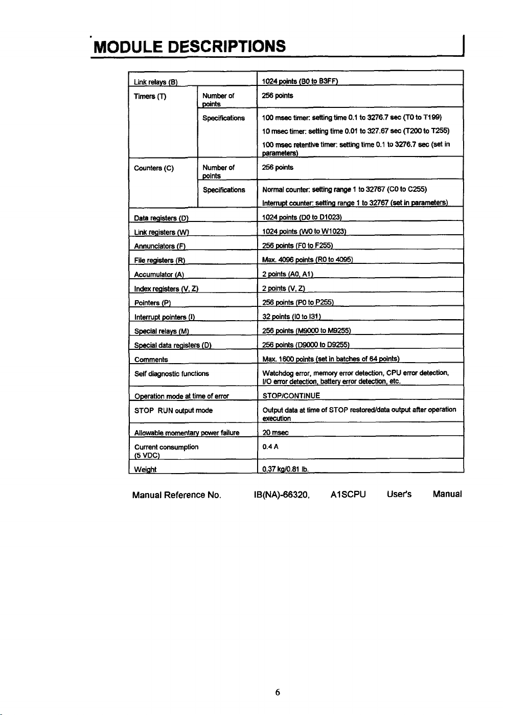
Manual Reference No. IB(NA)-66320.
6
A1
SCPU
User's
Manual
Page 13
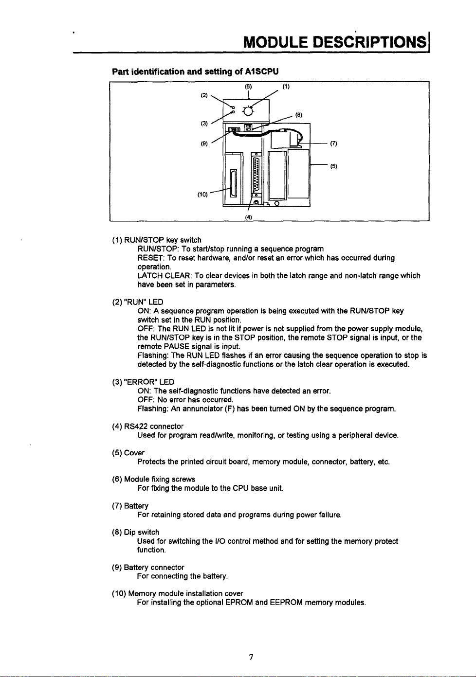
Part identification and setting
of
AISCPU
I
(1)
RUNlSTOP key switch
RUNASTOP: To startlstop running a sequence program
RESET: To reset hardware, and/or reset an error which has occurred during
operation.
LATCH CLEAR: To clear devices in both the latch range and non-latch range which
have been set in parameters.
(2) "RUN LED
ON:
A sequence program operation is being executed with the RUNlSTOP key
switch set in the RUN position.
OFF:
The RUN LED is not lit
the RUNlSTOP key
is
remote PAUSE signal is input.
flashing: The RUN LED flashes if an error causing the sequence operation to stop is
detected by the self-diagnostic functions or the latch clear operation is executed.
if
power
is
not supplied from the power supply module,
in the STOP position, the remote STOP signal is input, or the
(3)
"ERROR LED
ON: The self-diagnostic functions have detected an error.
OFF:
No error has occurred.
Flashing: An annunciator
(4)
RS422 connector
(F)
has been turned ON by the sequence program.
Used for program readhvrite, monitoring, or testing using a peripheral device.
(5)
Cover
Protects the printed circuit board, memory module, connector, battery, etc.
(6)
Module fixing screws
For fixing the module to the CPU base unit.
(7)
Battery
For retaining stored data and programs during power failure.
(8)
Dip switch
Used for switching the
IlO
control method and for setting the memory protect
function.
(9)
Battery connector
For connecting the battery.
(IO)
Memory module installation cover
For installing the optional EPROM and EEPROM memory modules.
7
Page 14
kPU
Base
Units
I
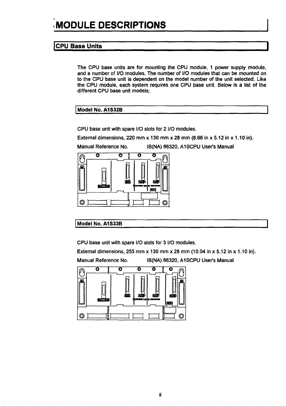
The CPU base units are for mounting the CPU module, 1 power supply module,
and a number of
to the CPU base unit is dependent
the CPU module, each system requires one CPU base unit. Below is a list of the
different CPU base unit models;
I
Model
No.
CPU base unit with spare
External dimensions,
Manual Reference No. IB(NA) 66320, AlSCPU User's Manual
1Model
No.
110
AI 5326
AlS33B
modules. The number
I/O
slots for 2
220
mm x 130 mm x 28 mm (8.66 in x 5.12 in x 1.10
of
I/O
on
the model number
110
modules.
modules that can be mounted
of
the unit selected. Like
in).
on
I
I
CPU base unit with spare 110 slots for
External dimensions, 255 mm
Manual Reference No. IB(NA) 66320, AlSCPU
3
I/O
modules.
x
130 mm x 28 mm (10.04 in x 5.12 in x 1.10 in).
8
User's
Manual
Page 15
I
Model
No.
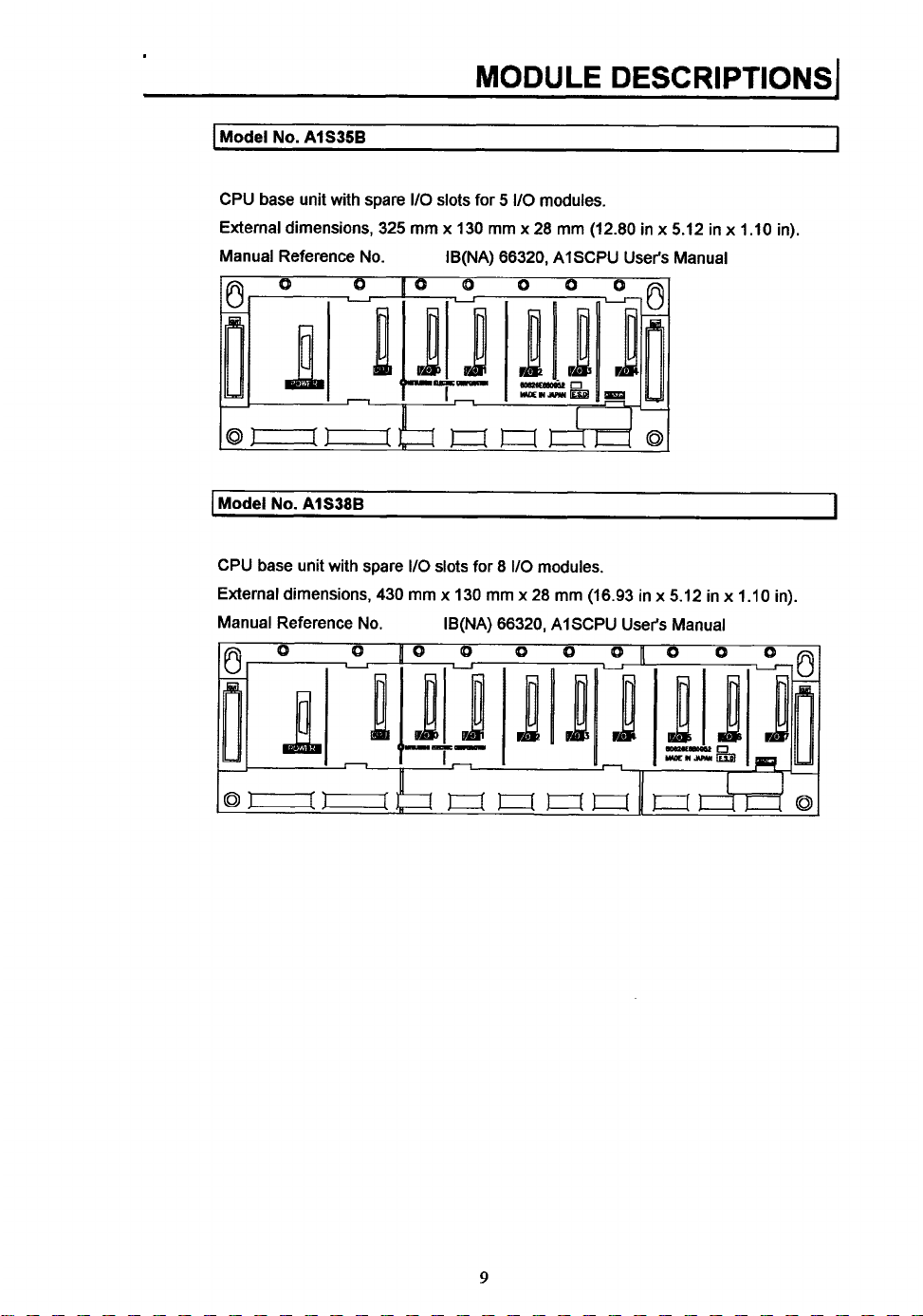
AlS35B
MODULE DESCRIPTIONS
I
I
CPU base unit with spare
External dimensions, 325
Manual Reference No. IB(NA) 66320, AISCPU User's Manual
I
Model
No.
AlS38B
CPU base unit with spare
External dimensions, 430
Manual Reference No.
110
slots
for
5
I/O
modules.
mm
x
130
mm x 28
110
slots for 8
mm
x
130
mm
IB(NA) 66320, AISCPU User's Manual
I10
modules.
x
28
mm
(12.80 in x 5.12 in x 1.10 in).
mm
(16.93 in x 5.12 in
x
1.10
I
in).
9
Page 16
MODULE
I
Extension Base
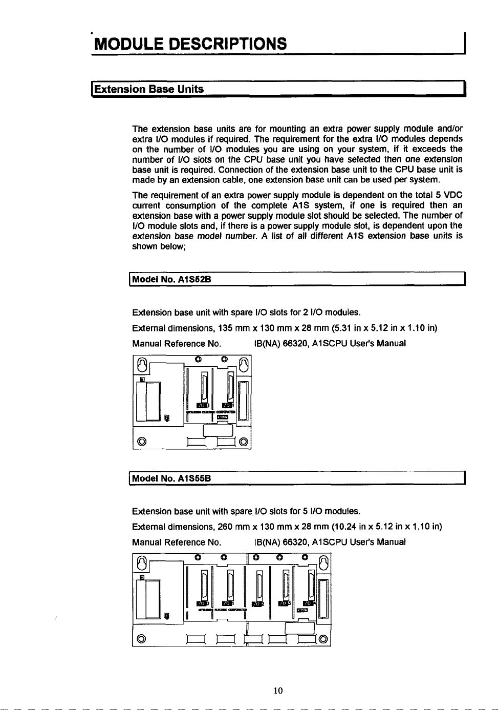
The extension base units are for mounting an extra power supply module andlor
extra
110
on the number of
number of
base unit is required. Connection of the extension base unit to the CPU base unit is
made by an extension cable, one extension base unit can be used per system.
The requirement of an extra power supply module is dependent on the total 5 VDC
current consumption of the complete A1S system, if one
extension base with a power supply module slot should be selected. The number of
110
module slots and, if there is a power supply module slot, is dependent upon the
extension base model number. A list of all different AIS extension base units
shown below;
I
Model
No.
DESCRIPTIONS
Units
modules if required. The requirement for the extra 110 modules depends
110
AlS52B
110
slots on the CPU base unit you have selected then
modules you are using on your system, if it exceeds the
is
required then an
one
extension
I
is
I
Extension base unit with spare
External dimensions, 135 mm x 130 mm x 28 mm (5.31 in x 5.12 in x 1.10 in)
Manual Reference No. IB(NA) 66320, AISCPU User's Manual
I
Model
No.
AlS55B
Extension base unit with spare, 110 slots for
External dimensions, 260 mm
Manual Reference
No.
110
slots for 2
x
130 mm
IB(NA) 66320,
x
110
modules.
5
110
modules.
28
mm (10.24 in x 5.12 in x 1.10 in)
AI
SCPU User's Manual
I
10
Page 17

I
Model
No.
A15588
MODULE
DESCRIPTIONS1
I
Extension base unit with spare
External dimensions, 365 mm
Manual Reference No. IB(NA) 66320, AISCPU User's Manual
I
Model
No.
AlS65B
Extension base unit with spare
module slot.
External dimensions, 315 mm x 130 mm x 28 mm (12.40 in x 5.12 in x I
Manual Reference No.
I/O
slots for 8 110
x
130 mm x 28 mm (14.37 in x 5.12 in
110
slots for
IB(NA) 66320, AISCPU
modules.
5
I10
modules and a power supply
User's
Manual
x
1.10
.10 in)
in)
1
I
Model
No.
AlS68B
Extension base unit with spare
module slot.
External dimensions, 420 mm
Manual Reference
No.
110
slots
for 5 110
x
130 mm x 28 mm (16.54 in x 5.12 in x 1.10 in)
IB(NA) 66320, AISCPU
11
modules and a power supply
User's
Manual
I
Page 18
1
I
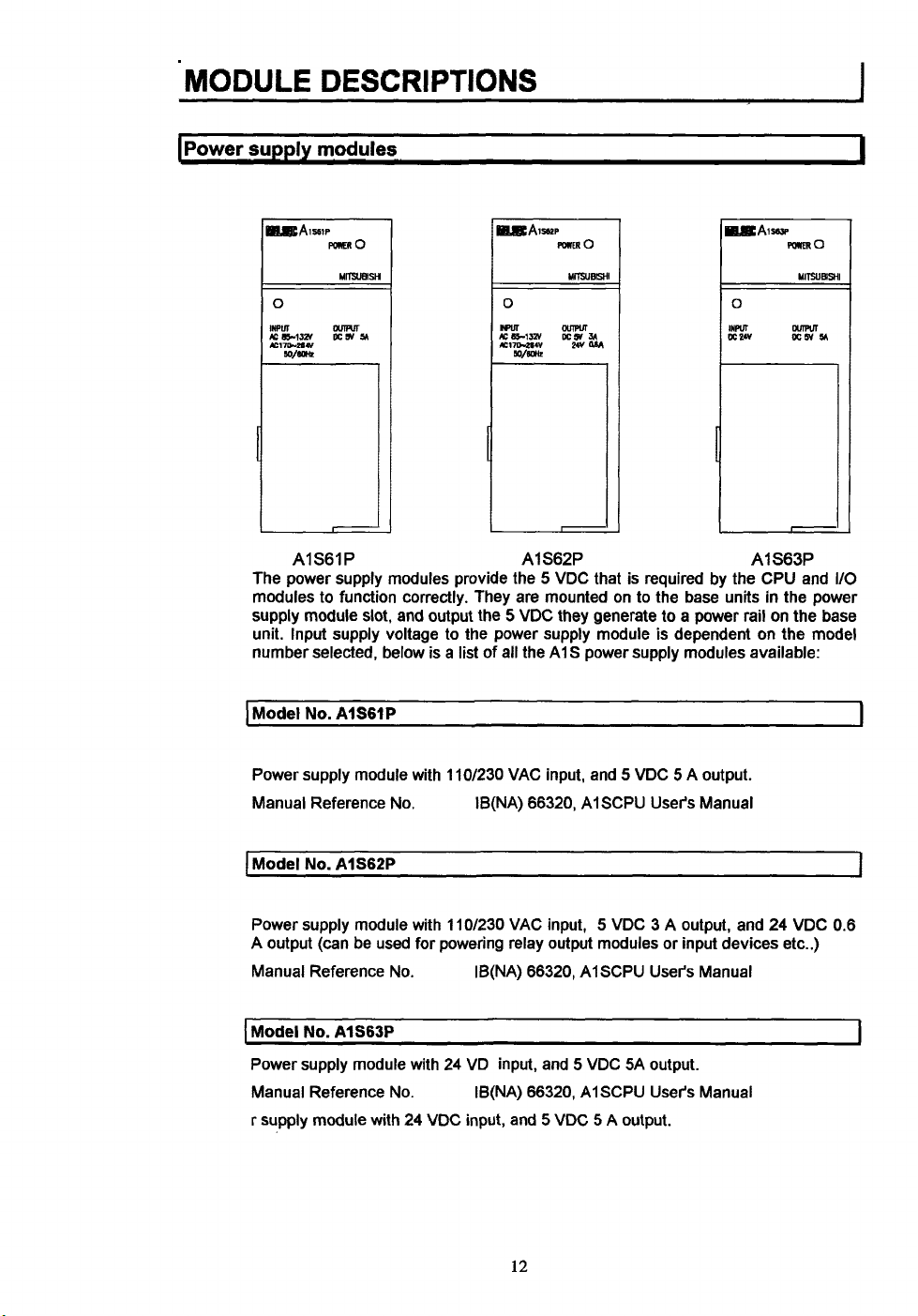
AIS61P
The power supply modules provide the 5 VDC that is required by the CPU and
modules to function correctly. They are mounted on to the base units in the power
supply module slot, and output the
unit. Input supply voltage to the power supply module is dependent on the model
number selected, below is
I
Model
No.
AISGIP
Power supply module with 110/230 VAC input, and 5 VDC 5 A output.
Manual Reference
I
Model
No.
AlS62P
No.
a
list of all the A1 S power supply modules available:
AlS62P AlS63P
5
VDC they generate to a power rail on the base
IB(NA) 66320, AISCPU User's Manual
I/O
1
I
Power supply module with 11Of230 VAC input, 5 VDC 3 A output, and 24 VDC 0.6
A output
Manual Reference No. IB(NA) 66320, AlSCPU User's Manual
I
Model
Power supply module with 24 VD input, and 5 VDC SA output.
Manual Reference No.
r supply module with 24 VDC input, and
(can
be used for powering relay output modules or input devices etc..)
No.
AlS63P
~~ ~
IB(NA) 66320, AISCPU User's Manual
5
VDC 5 A output.
12
I
Page 19
.. ..
MODULE
DESCRIPTIONS1
t
"'I
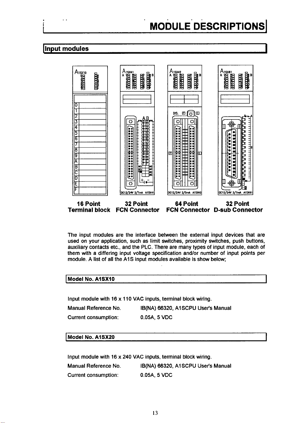
Terminal block
The input modules are the interface between the external input devices that are
used on your application, such as limit switches, proximity switches, push buttons,
auxiliary contacts etc., and the PLC. There are many types of input module, each of
them with a differing input voltage specification and/or number of input points per
module. A
16
I
Point
list
of all the AIS input modules available
32
Point
FCN Connector
64
Point
FCN Connector
is
show below;
D-sub
Connector
Model
No.
AISXIO
Input module with 16 x 110 VAC inputs, terminal block wiring.
Manual Reference No.
Current consumption: 0.05A,
I
Model
No.
AISXZO
Input module with 16 x
Manual Reference No.
Current consumption: 0.05A,
IB(NA)
66320,
AISCPU User's Manual
5
VDC
240
VAC inputs, terminal block wiring.
66320,
IB(NA)
13
AI SCPU User's Manual
5
VDC
I
I
Page 20
*
. .
. . .
..
MODULE
I
Model
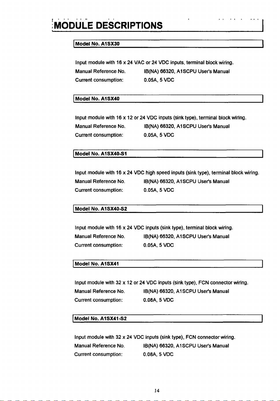
Input module with 16 x 24 VAC or 24 VDC inputs, terminal block wiring.
Manual Reference No.
Current consumption: O.O5A,
I
Model
Input module with 16 x 12 or 24 VDC inputs (sink type), terminal block wiring.
Manual Reference No.
Current consumption: 0.05A,
I
Model
Input module with 16 x 24 VDC high speed inputs (sink type), terminal block wiring.
Manual Reference No.
Current consumption: O.O5A,
..
DESCRIPTIONS
No.
AlSXSO
IB(NA) 66320, A1 SCPU User's Manual
No.
AlSX40
IB(NA) 66320, AISCPU User's Manual
No.
AlSX40-W
IB(NA) 66320, AlSCPU User's Manual
5
5
5
VDC
VDC
VDC
..
..
. ...
.
I
I
I
I
Model
No.
AlSX4052
Input module with 16 x 24 VDC inputs (sink type), terminal block wiring.
Manual Reference No.
Current consumption: 0.05A.
I
Model
No.
AlSX41
Input module with 32 x 12 or 24 VDC inputs (sink type), FCN connector wiring.
Manual Reference No.
Current consumption: 0.08A,
Model
No.
AlSX4lS2
Input module with 32 x 24 VDC inputs (sink type), FCN connector wiring.
Manual Reference No.
Current consumption: O.O8A,
IB(NA) 66320, AlSCPU User's Manual
5
VDC
IB(NA) 66320, A1 SCPU User's Manual
5
VDC
IB(NA) 66320, AlSCPU User's Manual
5
VDC
I
I
I
14
Page 21
MODULE DESCRIPTIONS~
I
Model
No.
AlSX42
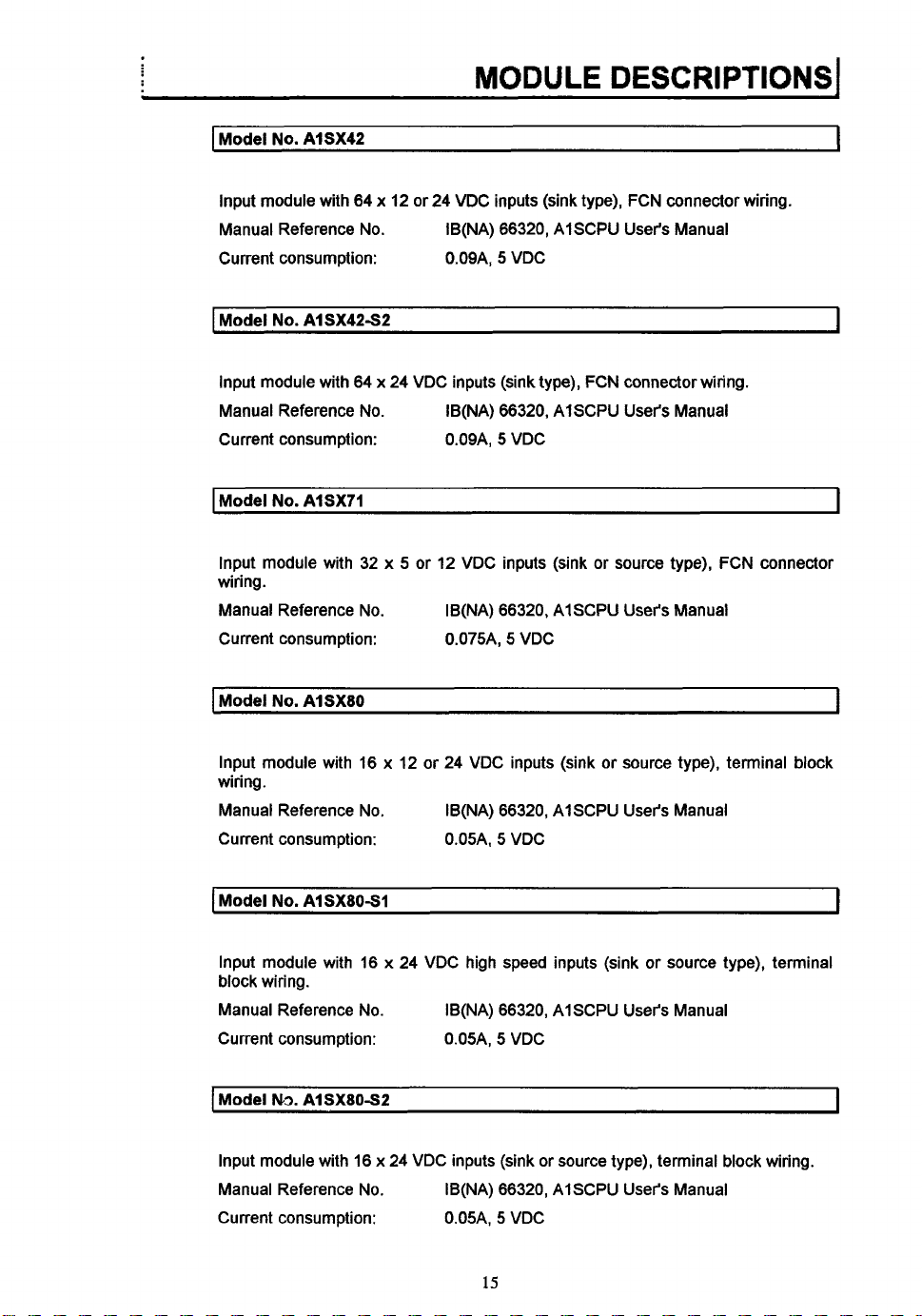
Input module with 64 x 12 or 24 VDC inputs (sink type), FCN connector wiring.
Manual Reference No.
Current consumption: 0.09A,
1
Model
No.
AI SX42S2
Input module with 64 x 24 VDC inputs (sink type), FCN connector wiring.
Manual Reference No.
Current consumption: O.O9A,
I
Model
No.
AlSX71
IB(NA) 66320, AISCPU User's Manual
5
VDC
IB(NA) 66320, AlSCPU User's Manual
5
VDC
I
I
I
Input module with 32 x 5
wiring.
Manual Reference No.
Current consumption: O.O75A,
I
Model
No.
AlSX8O
Input module with 16 x 12 or 24 VDC inputs (sink or source type), terminal block
wiring.
Manual Reference No.
Current consumption: O.O5A,
1
Model
No.
AlSX80-W
Input module with 16 x 24 VDC high speed inputs (sink or source type), terminal
block wiring.
Manual Reference No.
Current consumption: 0.05A, 5 VDC
I
Model
N3.
AISX80S2
or 12 VDC inputs (sink or source type), FCN connector
IB(NA) 66320, AISCPU User's Manual
5
VDC
IB(NA) 66320, AISCPU User's Manual
5
VDC
User's
IB(NA) 66320, AISCPU
Manual
i
I
I
Input module with 16 x 24 VDC inputs (sink or source type), terminal block wiring.
Manual Reference No.
Current consumption: 0.05A,
IB(NA) 66320, AISCPU User's Manual
5
VDC
15
Page 22
MODULE
I
Model
DESCRIPTIONS
No.
AlSX81
I
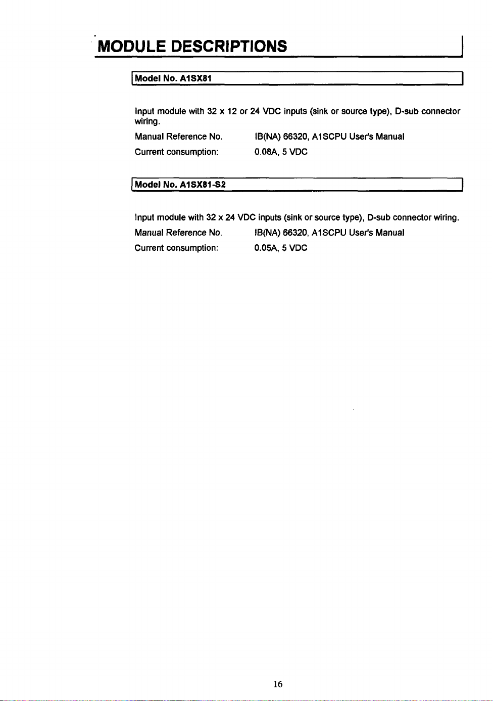
Input module with 32 x 12
wiring.
Manual Reference
Current consumption: 0.08A, 5 VDC
I
Model
No.
Input module with 32 x 24 VDC inputs (sink
Manual Reference
Current consumption: 0.05A, 5 VDC
No.
AlSX81S2
No.
or
24 VDC inputs (sink
IB(NA) 66320, AI SCPU User's Manual
IB(NA) 66320, AISCPU User's Manual
or
source type), D-sub connector
~
or
source type), D-sub connector wiring.
I
16
Page 23
MODULE
DESCRIPTIONS1
I
loutnut
modules
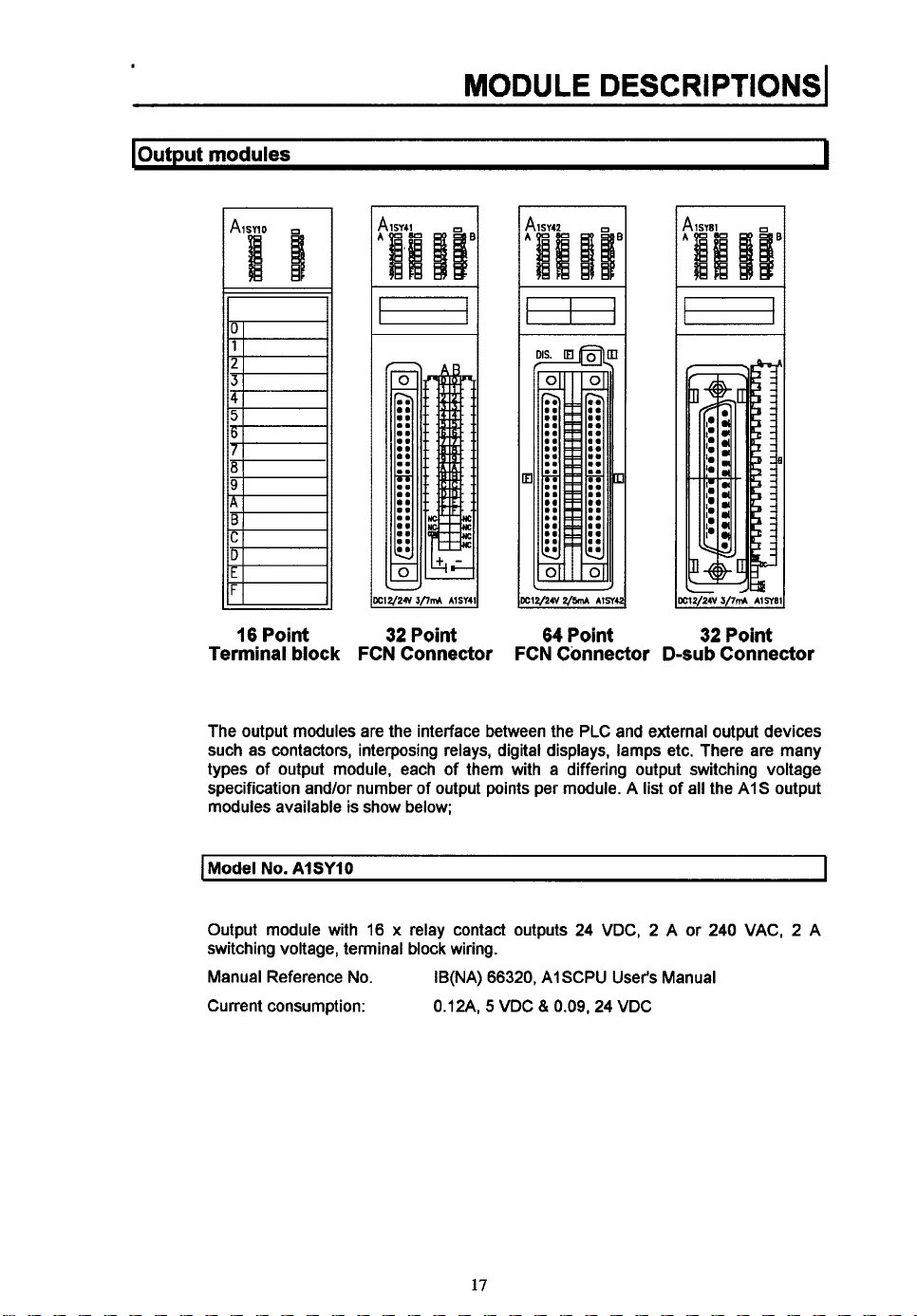
16
Point
Terminal
block
32
Point
FCN Connector
3
c12/24v2/m
FCN Connector D-subConnector
64
r1ne
Point
32/21
32
3/7&
Point
AlSY8l
I
The output modules are the interface between the PLC and external output devices
such as contactors, interposing relays, digital displays, lamps etc. There are many
types of output module, each of them with a differing output switching voltage
specification and/or number of output points per module. A list
modules available is show below;
I
Model
No.
AlSYlO
Output module with
switching voltage, terminal block wiring.
Manual Reference No.
Current consumption:
16 x relay contact outputs
IB(NA)
66320,
AISCPU User's Manual
5
WDC
81
0.12A,
0.09,24
24
WDC, 2 A or
WDC
of
all the AIS output
240
WAC, 2 A
I
17
Page 24
I
Model
No.
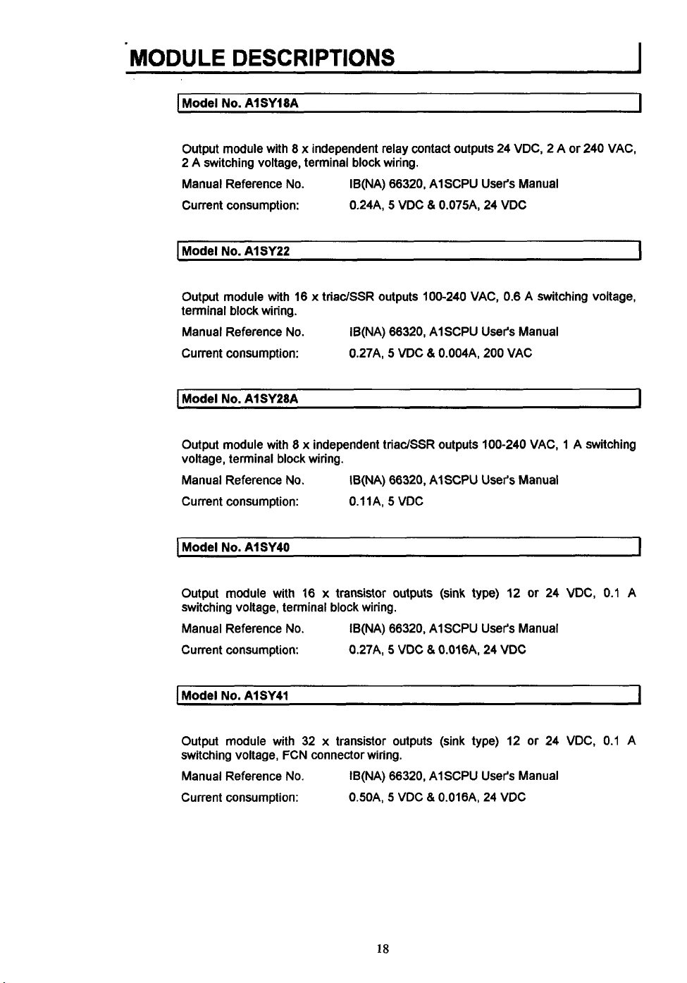
AlSY18A
Output module with 8 x independent relay contact outputs 24 VDC, 2 A or 240 VAC,
2 A switching voltage, terminal block wiring.
Manual Reference No.
Current consumption:
Model
No.
AlSY22
Output module with 16 x triaciSSR outputs 100-240 VAC, 0.6 A switching voltage,
terminal block wiring.
Manual Reference No.
Current consumption:
I
Model
No.
AlSY28A
Output module with 8 x independent triadSSR outputs 100-240 VAC, 1 A switching
voltage, terminal block wiring.
Manual Reference No.
Current consumption:
IB(NA) 66320, A1 SCPU User's Manual
&
0.24A, 5 VDC
IB(NA) 66320, AlSCPU User's Manual
0.27A, 5 VDC
IB(NA) 66320, AI SCPU User's Manual
0.1 lA, 5 VDC
O.O75A, 24 VDC
&
O.O04A, 200 VAC
I
I
I
[Model
I
No.
AlSY40
Output module
switching voltage, terminal block wiring.
Manual Reference No.
Current consumption:
Model
No.
Output module with 32 x transistor outputs (sink type) 12 or 24 VDC, 0.1 A
switching voltage, FCN connector wiring.
Manual Reference
Current consumption:
with
AlSY41
16 x transistor outputs (sink type) 12
IB(NA) 66320, AlSCPU User's Manual
No.
0.27A, 5
IB(NA) 66320, AlSCPU User's Manual
0.50A, 5 VDC
18
VDC
& 0.016A. 24 VDC
&
O.O16A, 24 VDC
or
24 VDC, 0.1 A
I
I
Page 25
I
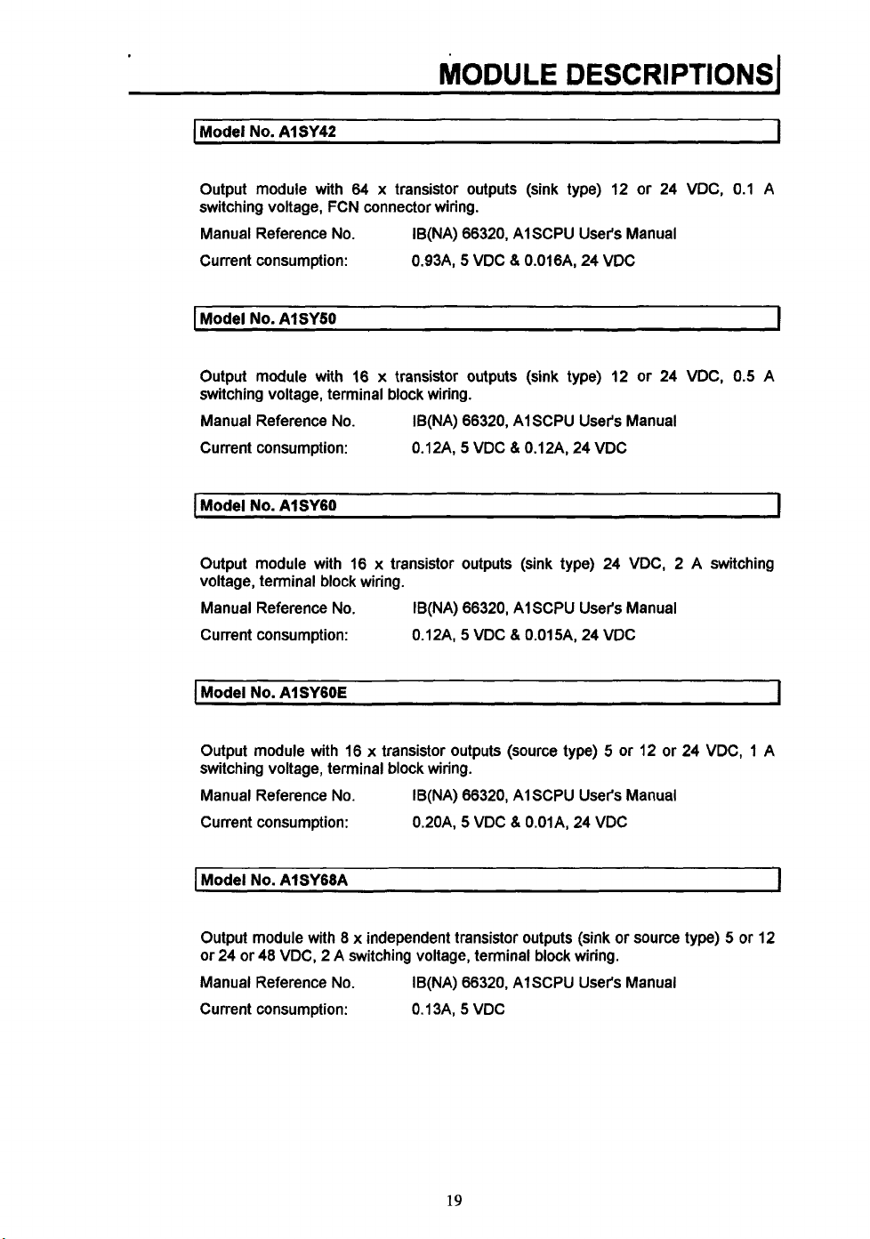
Model
No.
AlSY42
I
Output module with
switching voltage, FCN connector wiring.
Manual Reference No.
Current consumption:
I
Model
No.
AlSY50
Output module with 16 x transistor outputs (sink type) 12 or 24 VDC,
switching voltage, terminal block wiring.
Manual Reference No.
Current consumption:
I
Model
No.
AISYGO
Output module with
voltage, terminal block wiring.
Manual Reference No.
Current consumption:
I
Model
No.
AISYGOE
64
x
transistor outputs (sink type) 12 or 24 VDC, 0.1
IB(NA) 66320, AISCPU User's Manual
5
0.93A,
IB(NA) 66320, AISCPU User's Manual
0.12A,
~
16
x
transistor outputs (sink type) 24 VDC, 2 A switching
IB(NA) 66320, AISCPU User's Manual
0.12A,
VDC 8 0.016A, 24 VDC
5
VDC & 0.12A, 24 VDC
5
VDC &
O.O15A,
24 VDC
0.5
A
I
A
I
I
Output module with 16 x transistor outputs (source type) 5 or 12 or 24 VDC, 1 A
switching voltage, terminal block wiring.
Manual Reference No.
Current consumption:
I
Model
No.
AlSY68A
Output module with 8 x independent transistor outputs (sink or source type) 5 or 12
or 24 or 48 VDC, 2 A switching voltage, terminal block wiring.
Manual Reference No.
Current consumption: 0.13A,
IB(NA) 66320, AISCPU User's Manual
5
0.20A,
IB(NA) 66320, AISCPU User's Manual
VDC & 0.01A, 24 VDC
5
WDC
19
I
Page 26
MODULE
I
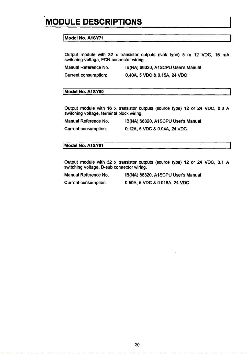
Model
No.
Output module with 32 x transistor outputs (sink type) 5 or 12 VDC, 16 mA
switching voltage, FCN connector wiring.
Manual Reference No.
Current consumption:
I
Model
No.
DESCRIPTIONS
AISY71
IB(NA) 66320, AI SCPU User's Manual
5
0.40A,
AISYIO
I
VDC & O.I5A, 24 VDC
I
Output module with 16 x transistor outputs (source type) 12 or 24 VDC,
switching voltage, terminal block wiring.
Manual Reference No.
Current consumption:
I
Model
No.
AISYII
Output module with 32 x transistor outputs (source type) 12 or 24 VDC,
switching voltage, D-sub connector wiring.
Manual Reference
Current consumption:
No.
IB(NA) 66320, AISCPU User's Manual
5
0.12A,
IB(NA) 66320, AISCPU User's Manual
0.50A,
VDC & O.O4A, 24 VDC
5
VDC & O.O16A, 24 VDC
-
0.8
0.1
A
-1
A
20
Page 27
!.
I
..
MODULE
DESCRIPTIONSI
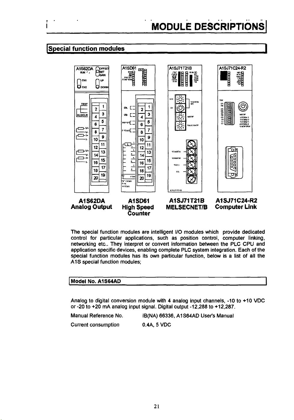
ISpecial
function
a
A1 S62DA
Analog
modules
Output
A1 SD61
High Speed
Counter
A1 SJ71 T21
MELSECNET/B
B
I
AlSJTl C24-R2
Computer Link
The special function modules are intelligent
control for particular applications, such as position control, computer linking,
networking etc.. They interpret or convert information between the PLC CPU and
application specific devices, enabling complete PLC system integration. Each of the
special function modules has its own particular function, below is a list of all the
AIS special function modules;
I
Model No.
Analog to digital conversion module with 4 analog input channels,
or
-20 to +20 mA analog input signal. Digital output -12,288 to +12,287.
Manual Reference
Current consumption 0.4A,
AlS64AD
No.
IB(NA) 66336, AlS64AD User's Manual
5
21
VDC
I/O
modules which provide dedicated
-10
to +IO VDC
I
Page 28
MODULE
I
Model
No.
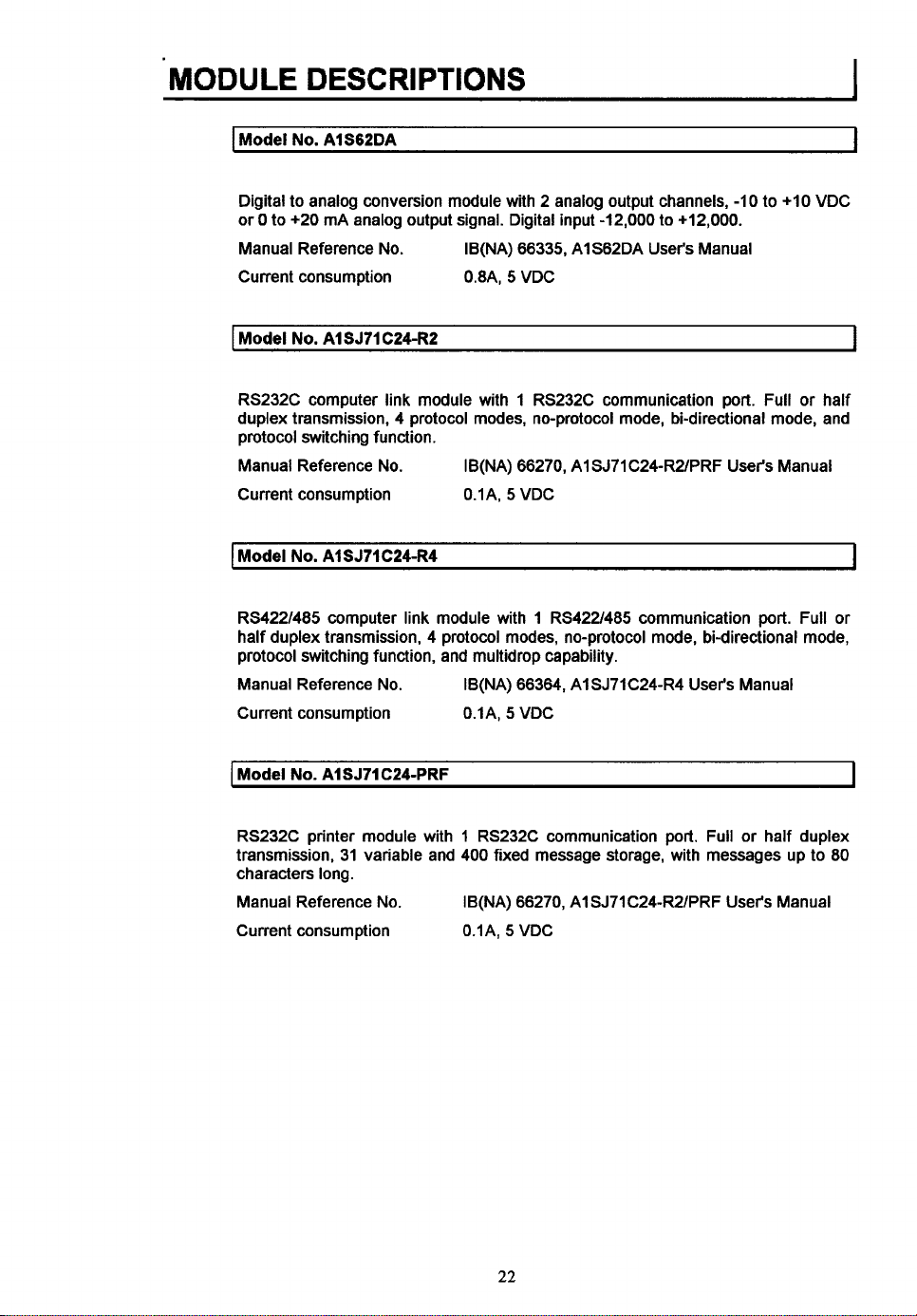
Digital to analog conversion module with 2 analog output channels, -1 0 to +10 VDC
0
to +20 mA analog output signal. Digital input -12,000 to +12,000.
or
Manual Reference No.
Current consumption OBA,
I
Model
No.
RS232C computer link module with 1 RS232C communication port. Full or half
duplex transmission, 4 protocol modes, no-protocol mode, bi-directional mode, and
protocol switching function.
Manual Reference No.
Current consumption
I
Model
No.
RS422/485 computer link module with 1 RS42Z485 communication port. Full or
half duplex transmission, 4 protocol modes, no-protocol mode, bi-directional mode,
protocol switching function, and multidrop capability.
Manual Reference No.
Current consumption O.lA,
DESCRIPTIONS
AlS62DA
IB(NA) 66335, AlS62DA User's Manual
5
VDC
AlSJllC24-RZ
IB(NA) 66270, A1 SJ71 C24-RZPRF User's Manual
O.IA,
5
VDC
AlSJ71C24R4
IB(NA) 66364, AlSJ7lC24-R4 User's Manual
5
VDC
I
I
I
I
I
Model
No.
AISJ71C24-PRF
RS232C printer module with 1 RS232C communication port. Full or half duplex
transmission, 31 variable and 400 fixed message storage, with messages up to
characters long.
Manual Reference No.
Current consumption
IB(NA) 66270, A1 SJ71 C24-R2/PRF User's Manual
O.lA,
5 VDC
22
I
80
Page 29
I
Model
No.
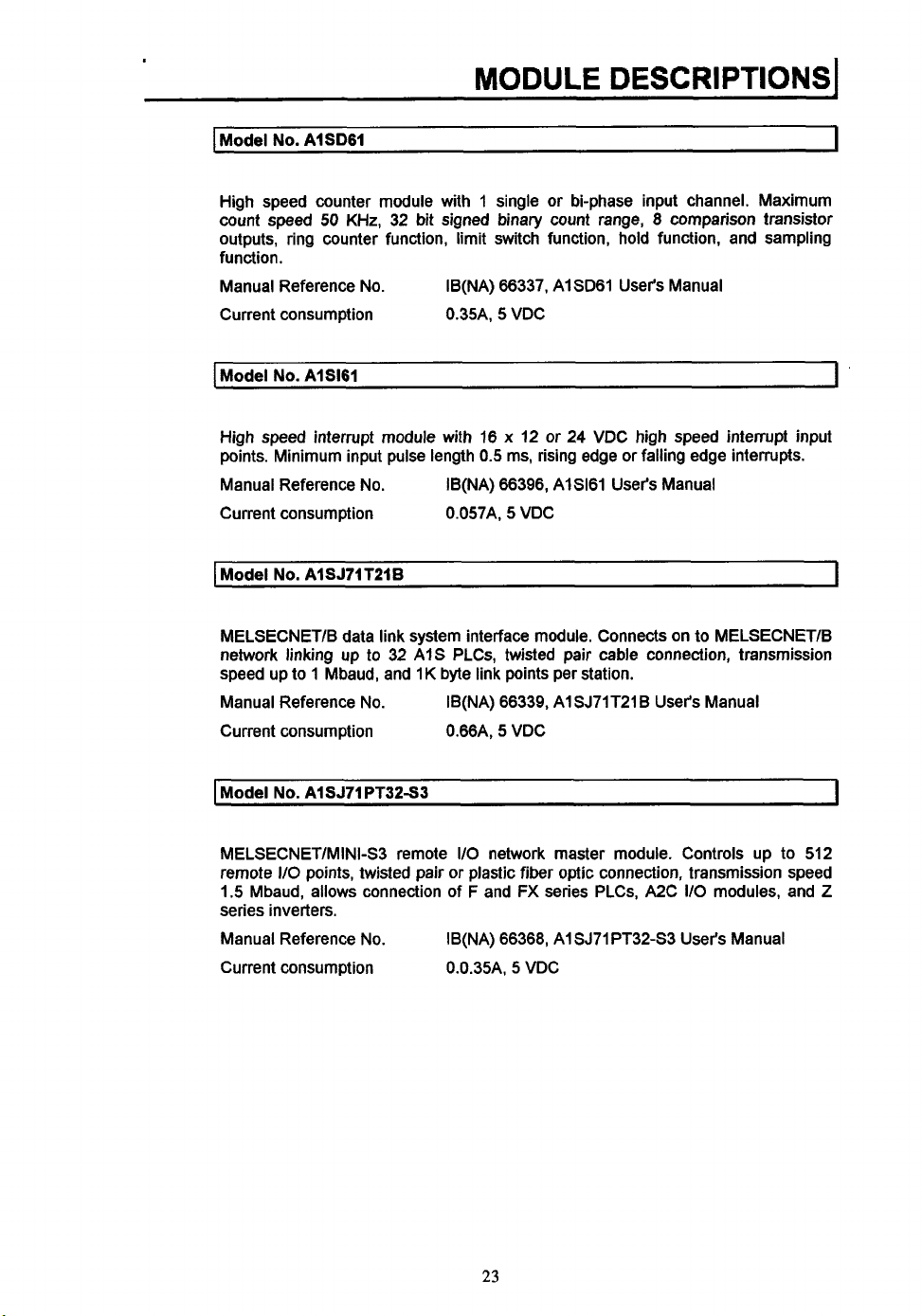
AISD61
MODULE
DESCRIPTIONS~
I
High speed counter module with 1 single or bi-phase input channel. Maximum
count speed
outputs, ring counter function, limit switch function, hold function, and sampling
function.
Manual Reference No.
Current consumption 0.35A,
I
Model
High
speed
points. Minimum input pulse length
Manual Reference No.
Current consumption 0.057A,
I
Model
MELSECNET/B data link system interface module. Connects on
network linking up to 32
speed up to
Manual Reference No.
Current consumption 0.66A,
50
KHz, 32 bit signed binary count range, 8 comparison transistor
IB(NA) 66337, AISD61 User's Manual
5
VDC
No.
AIS161
interrupt module with 16 x 12 or 24 VDC high speed interrupt input
0.5
ms, rising edge or falling edge interrupts.
IB(NA) 66396, AIS161 User's Manual
5
VDC
No.
AlSJ71 T21
1
Mbaud, and
B
AIS
PLCs, twisted pair cable connection, transmission
1
K byte link points per station.
IB(NA) 66339, AI SJ71 T21 B User's Manual
5
VDC
to
MELSECNET/B
I
I
I
Model
No.
AlSJ71PT32-W
MELSECNET/MINI-S3 remote
remote I/O points, twisted pair or plastic fiber optic connection, transmission speed
1.5 Mbaud, allows connection of
series inverters.
Manual Reference No.
Current consumption 0.0.35A,
I/O
network master module. Controls up to
F
and
FX
series PLCs, A2C
IB(NA) 66368, A1 SJ71 PT32-S3 User's Manual
5
VDC
23
I/O
modules, and
512
I
Z
Page 30
MODULE
I
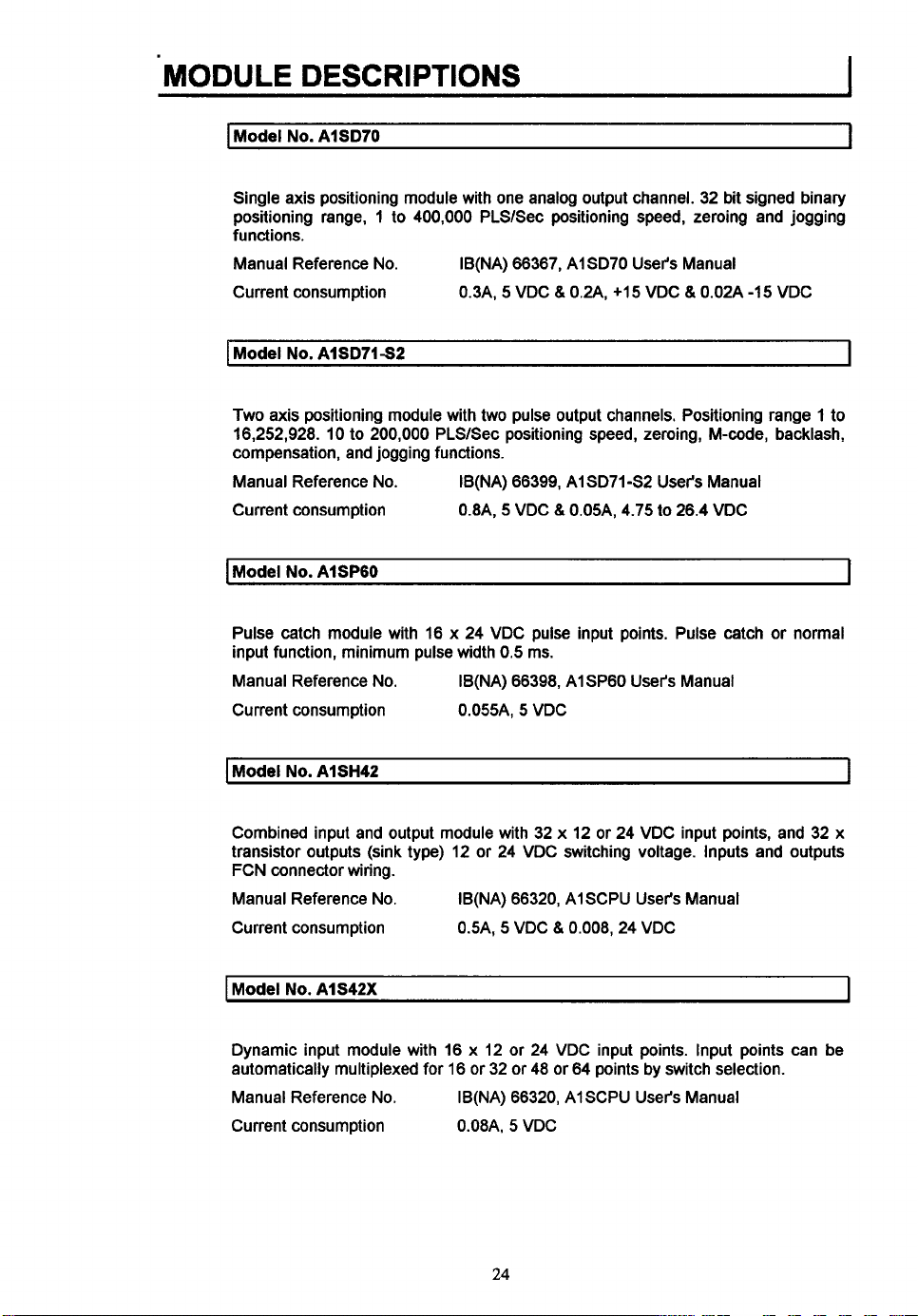
Model
Single axis positioning module with one analog output channel. 32 bit signed binary
positioning range, 1 to 400,000 PLSlSec positioning speed, zeroing and jogging
functions.
Manual Reference No. IB(NA) 66367, AlSD70 User's Manual
Current consumption 0.3A,
I
Model
DESCRIPTIONS
No.
AISD7O
No.
AlSD71S2
5
VDC
8
024,
+15 VDC & 0.02A
1
-1 5 VDC
I
Two axis positioning module with
16,252,928. 10 to 200,000 PLSlSec positioning speed, zeroing, M-code, backlash,
compensation, and jogging functions.
Manual Reference No.
Current consumption
Model
No.
AISPGO
Pulse catch module with 16 x 24 VDC pulse input points. Pulse catch or normal
input function, minimum pulse width
Manual Reference No.
Current consumption 0.055A,
I
Model
No.
AlSH42
Combined input and output module with 32 x 12 or 24 VDC input points, and 32 x
transistor outputs (sink type) 12 or 24 VDC switching voltage. Inputs and outputs
FCN connector wiring.
Manual Reference No.
Current consumption
two
pulse output channels. Positioning range 1 to
IB(NA) 66399, AlSD7142 User's Manual
0.8A,
5
VDC &0.05A, 4.75 to 26.4 VDC
0.5
ms.
IB(NA) 66398, AlSP6O User's Manual
5
VDC
IB(NA) 66320, AlSCPU User's Manual
5
VDC & 0.008,24 VDC
0.5A,
I
I
I
Model
No.
AlS42X
Dynamic input module with 16 x 12 or 24 VDC input points. Input points can be
automatically multiplexed for 16 or 32 or 48 or 64 points by switch selection.
Manual Reference No.
Current consumption 0.08A,
IB(NA) 66320, AlSCPU User's Manual
5
VDC
24
I
Page 31

Model
No.
AIS42Y
MODULE
DESCRIPTIONS
I
I
Dynamic output module with 16 x transistor outputs (sink type) 12
switching voltage. Output points can
or
64 points by switch selection.
Manual Reference No.
Current consumption
I
Model
No.
AISG6O
I/O
slot blanking module for filling unused I/O slots on the base units.
Manual Reference No. IB(NA) 66320, AISCPU User's Manual
Current consumption None
I
Model
No.
AlSG62
Dummy I/O point module for reservation of I/O points for future additions to the
PLC system. 16
Manual Reference No.
Current consumption None
Model
No.
or
32
AlS62RD3
or
48
of
be
automatically multiplexed for 16
IB(NA) 66320, AISCPU User's Manual
O.IA,
5
VDC & 0.008A 24 VDC
64
110
points can be reserved by switch setting.
IB(NA) 66320, AISCPU User's Manual
or
24 VDC
or
32 or 48
I
I
I
3 wire temperature sensor input module with two sensor input channels. Compatible
with 3 wire PTIOO temperature sensors, 16 or 32 bit binary sensing value, and wire
breakage detection.
Manual Reference No.
Current consumption 0.54A, 5 VDC
I
Model
No.
AlS62RD4
4 wire temperature sensor input module with two sensor input channels. Compatible
with 4 wire PT100 temperature sensors, 16 or 32 bit binary sensing value, and wire
breakage detection.
Manual Reference No.
Current consumption 0.44A,
IB(NA) 66338, AIS62RD3/4 User's Manual
IB(NA) 66338, AlS62RD3/4 User's Manual
5
VDC
25
I
Page 32

..
..
MODULE
I
Model
.
..
DESCRIPTIONS
No.
AlST6O
...
......
_.
I
Timer module with 8 analog timers. Timer range
accuracy.
IB(NA)
66397,
Manual Reference
Current consumption
No.
0.055A, 5 VDC
AIST6O
0.1
to
000
User's Manual
seconds with a
+/-
2%
26
Page 33

..
MODULE
DESCRIPTIONS1
pmofmodules
I
Model
No.
EEPROM memory module with a capacity
Manual Reference No. IB(NA)
I
Model
No.
EEPROM memory module with a capacity
Manual Reference
AlSMCA-2KE
AlSMCA-8KE
No.
The memory modules allow EEPROMs and EPROMs
to be used for program storage, in addition to the
memory in the CPU module.
of
8k
bytes
(2k
steps).
66320,
AlSCPU User's Manual
of
32k
bytes
(8k
steps).
IB(NA)
66320,
AISCPU User's Manual
RAM
I
I
I
t
Model
No.
AlSMCA-8KP
EPROM memory module with a capacity of
Manual Reference No.
IB(NA)
66320.
27
8k
bytes
(2k
steps).
AISCPU User's Manual
I
Page 34

..
1
MODULE
I
Extension
cables
*.
DESCRIPTIONS
..
I
I
I
The extension cables are for connecting the
extension base units
Different cable lengths are available according
the model number. A list of the AIS extension
cables is shown below;
I
Model
No.
AlSCOlB
Extension base to CPU base,
Manual Reference No.
I
Model No. AlSC03B
Extension base to CPU base,
Manual Reference No. IB(NA)
I
Model
No.
AlSClZB
Extension base to CPU base,
Manual Reference No.
5.5
cm long.
IB(NA)
33
cm long.
120
IB(NA)
66320,
66320,
cm long.
66320,
to the CPU base units.
to
1
AISCPU User's Manual
I
AISCPU User's Manual
I
AISCPU User's Manual
I
Model
No.
AlSCJOB
Extension base to CPU base,
Manual Reference No.
I
Model No. AlSCOBNB
AnN extension base to AIS CPU base,
Manual Reference No, IB(NA)
300
IB(NA)
cm long.
66320,
45
66320,
28
1
AISCPU User's Manual
I
cm long.
AlSCPU User's Manual
Page 35

..
i
..
MODULE
DESCRIPTIONS1
(Terminal
Remote terminal block units for use with connector wiring type input and output
modules. Connected
many types of terminal block unit with a differing number of terminal points and/or
compatible with different
There are
modules, and the other for use with source type input/output modules. Below is a
list of the
block
units and cables
32
Point
D-sub Connector
two
types
AIS
terminal block units and cables available
36
Point Terminal
Block
D-sub Connector
to
the
110
modules using a terminal block cable. There are
110
modules.
of
terminal block cable, one for use with sink type inputloutput
1
1
Model
No.
A6TBXY36
36 point terminal block unit for use with sink type input and output modules,
AlSX41(S2), AlSX42(S2), AlSY41, AISY42,
Manual Reference
I
Model
No.
54
point terminal block unit for use with sink type input and output modules,
A1 SX41 (S2), AI SX42(S2), AI SY41, AlSY42,
Manual Reference
No.
A6TBXY54
No.
No
manual, specification sheet No. 88
No
manual, specification sheet
29
or
AlSH42.
or
Ai SH42.
No.
88
I
I
Page 36

MODULE
I
Model
70
point terminal block unit for use with sink type input modules,
AlSX42(S2),
Manual Reference
I
Model
DESCRIPTIONS
No.
A6TBX70
or
AlSH42.
No.
A6TBX36-E
No.
No
manual, specification sheet
No.
AlSX41(S2),
88
I
I
I
I
36 point terminal block unit for use with source type input module,
Manual Reference
1
Model
No.
36
point terminal block unit for use with source type output module,
Manual Reference
I
Model
No.
54
point terminal block unit for use with source type input module,
Manual Reference
I
Model
No.
54
point terminal block unit for use with source type output module,
Manual Reference
I
Model
No.
No.
A6TBY36-E
No.
A6TBX54-E
No.
A6TBY54-E
No.
A6TBX70-E
No
manual, specification sheet
No manual, specification sheet
No
manual, specification sheet
No
manual, specification sheet
AlSX81(S2).
No.
88
AISY81.
No.
88
AlSX81(S2).
No.
88
AlSY81.
No.
88
I
I
I
1
70
point terminal block unit for use with source type input module,
Manual Reference
I
Model
No.
Terminal block unit cable for use with sink type terminal block units and input/output
modules,
Manual Reference
0.5
ACOBTB
m long.
No.
No.
No
manual, specification sheet
No
manual, specification sheet
30
A1 SX81 (S2).
No.
88
No.
88
I
Page 37

..
.
I
MODULE
DESCRIPTIONS1
.I
[Model
I
I
No.
ACIOTB
Terminal block unit cable for use with sink type terminal block units and inputloutput
modules,
Manual Reference
Model
Terminal block unit cable for use with sink type terminal block units and inputloutput
modules,
Manual Reference
Model
Terminal block unit cable for use with sink type terminal block units and inputloutput
modules,
Manual Reference
Model
1
m long.
No.
ACZOTB
2 m long.
No.
AClOTB
3
m long.
No.
AC50TB
No.
No.
No.
No
manual, specification sheet
No
manual, specification sheet
No
manual, specification sheet
No.
No.88
No.
88
88
1
I
I
I
Terminal block unit cable for use with sink type terminal block units and inputloutput
modules,
Manual Reference
I
Model
Terminal block unit cable for use with source type terminal block units and
inputloutput modules,
Manual Reference
I
Model
Terminal block unit cable for use with source type terminal block units and
inputloutput modules, 1 m long.
Manual Reference
5
m long.
No.
ACOCTB-E
No.
ACIOTB-E
No.
No.
No.
0.5
No
m long.
No
No
manual, specification sheet
manual, specification sheet
manual, specification sheet
No.
88
No.
88
No.
88
I
I
31
Page 38

..
MODULE
I
Model
DESCRIPTIONS
No.
ACZOTB-E
..
I
Terminal block unit cable for use with source type terminal block units and
inputloutput modules,
Manual Reference
Model
No.
ACSOTB-E
Terminal block unit cable for use with source type terminal block units and
inputloutput modules,
Manual Reference
I
Model
No.
ACSOTB-E
Term-inal block unit cable for use with source type terminal block units and
inputloutput modules,
Manual Reference
No.
No.
No.
2
m long.
3
m long.
5
m long.
No manual, specification sheet
No
manual, specification sheet
No
manual, specification sheet
No.
No.
No.
88
88
88
I
I
32
Page 39

I
Chapter
SELECTION
3:
System Selection and Configuration
AND
CONFIGURATION^
I
Jsystem selection
AIS
system selection may seem to be a difficult task with
of modules and accessories to choose from, as can be seen in chapter
it
can be made easy by following the five steps outlined in this chapter. Follow them
carefully and you will be able
application requirements.
to
match the
AIS
so
many different types
PLC
system exactly to your
2.
However,
I
33
Page 40

'SELECTION
I
Step
1:
Input module selection
AND
CONFIGURATION
I
12124 VDC
Sink or source
inputtype
?
16pOW
1
Sink
or
16,320r64
point modules
?
+
source Model number:
inputtype?
.
64 point Model number:
'
Sink
€4
point
Sink Model number:
16 point
t
Sink
L
Sink
source
Sink
L
r
Source
-
Source
-
Model number:
I
AlSX41
L
c
AlSX81
c
Model number.
AlSX42
h
I
Model number:
J
Model number.
\
1
1
1
4
Start
DC
inputs
AC, DC or
TTL
AC inputs
L
i
I
inputs
?
I
t
24
16 point
220
16 point
7-
Source
High
speed
inputtype
7
TTL
inputs
Sin k/source
32
point Model number:
VAC
11OVAC
16
24,110 or
220 V inputs
VAC
point
L
?
v
I
34
AlSX40S2
AlSXBOSl
Model number:
AlSXBOS2
U
Model number:
Model number:
Model number:
Page 41

I
Step
SELECTION
2:
Output module selection
AND
CONFIGURATION^
I
16
point
Ah
0.1,0.5
or 2 A
outputcurrent?
12I24VDC
1Zi24VDC
L
v
-
2A
24 VDC
0.1 A
Model number:
AlSY40
b
t
Model number:
AISYSO
I
*
Model number:
AISY6O
b
*
I
1
4
1
I
start
+
Transistor,
relay, Mac or
TTL outputs
Reky+
TTL
L
r
? Trk
7
32
point Sinkkource
1A
Independent
commons
Independent Model number:
commons
I
?
?
8point
0.6 A
100-240 VAC
16
point
2A
24VDC,lW240VAC
24 VDC,100-240 VAC
16
point Model number:
AlSY71
AlSY28A
AlSY22
-
AI SY18A
AISYIO
35
Page 42

-SELECTION
I
Step 3: Special function
AND
CONFIGURATION
module
selection
I
start
-
AID,
QIA
conversion
7r
No
TI
No
NetworKmg
I I
YeS
?
L
r
Yes
L
?
-
RemoteUOor
masterilocal
AID
or
QIA
conversion
7
1
?
Remote
L
v
Model number:
Model number:
VO
Model number:
r
Masterllocal Model number:
P
A1
SJ71T21
B
36
Model number:
Model number:
Model number:
4
wire
Model number:
Page 43

I
Step
SELECTION
4:
Power supply
module
AND
selection
CONFIGURATION^
I
Stad
-
vohge
?
r
Model number:
t-
\r
No
Model number:
Note:
1.
If
an AlS62P power supply unit has been selected, then ensure that the DC 5V
current consumption
does not exceed 3A.
power supply module should be selected, and an external power supply should
be used for the DC 24V that is required.
If
an AlS65B or AlS68B extension base are used, then an additional power
2.
supply module is required.
of
all the modules being powered by this power supply
If
the current consumption
is
above 3A, then an AIS61P
31
Page 44

:SELECTION
I
Step
5:
Base unit selection
AND
CONFIGURATION
I
.
b
Calculate the number
VO
slots
required.
More than
2
slots
requked
t
yes
3
More than
slots
required
t
yes
-
More than
5
slots
required
More than
8
slots
required
t
yes
I
More than
slots required
10
I
UO
UO
UO
VO
?
?
?
?
UO
?
of
No
L
v
No
L
r
No
L
r
t
Is
the total DC
r
consumption greaterthan
the power suppfy
5V
current
OP
?
I
T
r
Model number:
Model number:
AlS300
+
tY~
Is
More than
slots
required
t
13
yes
UO
?
the total
r
consumption greaterthan
the power supply O/P
Isthe total
consumption greater than
the power supply
38
!X
DC
I
5V
YeS
w
YeS
current
current
OIP
r
?
Model number:
(AlS65B
'L
r
?
L
Model number:
J
Page 45

SELECTION
AND
CONFIGURATION^
lsystem
configuration
After selecting all of the components for your AIS system, it is then necessary
configure the system and assign input/output numbers for each of the modules you
have chosen.
First of all each of the modules in your system must be allocated
either the CPU or extension base unit. So write in the model numbers of the
modules you have selected against the slot number where you want to locate them
on the base units selected. A good idea when doing this is to keep all the input
modules, output modules and special function modules together in groups, this
it
makes
When you have allocated an
to
range from
A,
base unit. From the module in slot 0 the numbers follow on consecutively through
all the modules on the CPU base unit and then on to the modules in the extension
base unit, if one is used. Please note when assigning the
I/O
modules occupy
much easier when it comes
assign numbers
B,
slot special function modules occupy 32 points, two
C,
D,
0
E,
to
to FF, and are counted in hexadecimal i.e.
F with the starting point for counting the module in slot 0 of the CPU
all of the inputs and outputs in your system. The numbers
48
points, and spare or vacant
I10
to
programming and installation later on.
slot
for each of the modules, it is then necessary
0,
110
110
slots
occupy 16 points.
to
an
110
1,
2, 3, 4,
I10
slot special function
5,
6,
numbers that single
slot on
7,
8,
to
9,
I
39
Page 46

!SELECTION
lAlS
System
I
Examples
System
System requirements:
Example
AC 240V input power supply
24
x
DC 24V source
x
relay contact outputs
16
x
DC 0-1OV analog inputs
2
1
x
DC 0-1OV analog output
AND
1
CONFIGURATION
type
inputs
Slot
number
01234
I
I
I
Required modules:
CPU base unit
Power supply module
CPU module
Slot 0
Slot
1
Slot 2
Slot
3
Slot
4
Total number
Total
DC 5V current consumption = 1.8A
of
I/O points used = 112
S35B
AI
A1
S61
P
A1 SCPU
AI SX81
AlSYlO
A1
S64AD
AI S62DA
Vacant
40
Page 47

SELECTION
I
Svstern
System requirements
EXamDle
AC 240V input power supply
x
AC 240V inputs
60
48
x
triac/SSR outputs
16
x
independent relay contact outputs
1
x
RS232C computer link
2
Slot
number
CPU
PS
AND
CONFIGURATION^
I
01234567
00
10 20 30 40
to
to
to
OFIF2F3F4F5F6F8F
to
to
50
to
60
to
70
to
I
0
Required modules
CPU base unit
Ext.
base unit
Ext.
cable
Power supply
CPU module
Slot
0 - 3
Slots 4
-
6
Slot 7
Slots 8
-
9
Total number
Total DC 5V current consumption
of
110
points used = 172
A1 S38B
A1
A1 SCO5B
A1
A1
A1
AI
AlSJ71C24-RZ
AI
S52B
S61 P
SCPU
SX20
SY22
SY18A
=
1.36A
41
Page 48

ISELECTION
AND
CONFIGURATION
I
System
System requirements
Example
DC
24V input power supply
100
80 x transistor source type outputs
Terminal block connections only
3
x
DC
24V source type inputs
Slot
number
&
01234567
8
9
10
11
12
I
Required modules
CPU
base unit
Ext.
base
unit
Ext.
cable
Power supply
CPU
module
Slots
0
-
6
Slots
7
-
I1
Slot 12
Total number
Total
DC
of
I/O
5V current consumption = 1.35A
AI S38B
AI
S55B
AI
SCO5B
AI S63P
AI
SCPU
AI SX80
AI SY80
Vacant
points used = 180
42
Page 49

i
I
System Example
System requirements
AC 11
16
16
1
1 x MELSECNET/B interface
SELECTION
4
OV input power supply
x
DC 24V source type inputs
x
relay contact outputs
x
high speed counter input
Slot
AND
number
CONFIGURATION^
I
&
01
PS
CPU
00
10
to
to
0
~~1
Required modules
CPU base unit
Ext.
base unit
Ext.
cable
Power supply
CPU module
Slot
0
Slot
1
Slot
2
Slot
3
Total number
Total DC
of
5V
current consumption = 1.58A
I
I/O
points used = 96
23
AI S32B
AI S52B
AI SC056
AI S61 P
AI SCPU
SX80
AI
AlSYlO
AI SD61
AI SJ71 T21 B
43
Page 50

INSTALLATION
I
Chapter
4:
Installation
llnstallation environment
An AIS PLC system should not be installed in the following environments;
1.
Locations where the ambient temperature is greater than 55
0
OC.
2.
Locations where the ambient relative humidity is
than
10%.
3. Locations where dew condensation occurs due to sudden changes in
temperature.
4. Locations where there are corrosive and/or combustible gasses.
5.
Locations where there is a high level
and iron filings, oil mist, salt, and organic solvents.
6.
Locations exposed to the direct rays of the sun.
7.
Locations where strong power and magnetic fields are generated.
8.
Locations where vibration and shock are directly transmitted to the
system.
OC
or less than
greater than
of
conductive powder, such as dust
90%
I
or less
PLC
44
Page 51

INSTALLATION^
[Base
unit mounting instructions
The
CPU
following instructions;
and extension base units should be mounted in accordance with the
1.
To
improve the ventilation of the
removal of any modules, allow a minimum
around the base unit.
Indicates the panel top, wiring
//////////////////////
Parallel
PLC
duct,
or any assembly
Mounting
and to facilitate the addition or
30
mm
11.18
in. clearance
or
more
I
D
-
Serial Mounting
45
-
30 mrn
30 mrn
Or
Inore
(1
.I7
(1.17
in.)
in.)
Page 52

!INSTALLATION
2.
So
as not to prevent correct ventilation, do not mount the base unit vertically
or horizontally.
Vertical Mounting Horizontal Mounting
3.
The base unit should be mounted on a flat surface
strain to the printed circuit boards which could result in damage or incorrect
operation.
Avoid mounting the base unit close to the source of any vibration, such
4.
large magnetic contactors and/or large no-fuse breakers. If possible mount
the base unit in a separate panel to the vibration source or mount it as far as
possible from the vibration source.
(Not allowed) (Not allowed)
so
as
to
I
prevent any
as
5.
If any equipment which generates noise or heat is positioned in front of the
PLC
system i.e. the equipment is mounted on the back of the panel door,
allow a minimum clearance
system and such equipment.
of
100
mW3.94 in. between the front
,
Panel,
etc.
Door
of
the
PLC
46
Page 53

INSTALLATION^
IMounting
Both the
provided on the back of them. Below the method of installation is explained;
the
base
units
on
DIN
rail
CPU
and extension base units can be fixed to
1.
Applicable
TH35-7.5 Fe, TH35-7.5 AI, and TH35-15 Fe.
2.
DIN
When TH35-7.5 Fe or TH35-7.5
unit, the space between the
less.
35
DIN
rails:
rail fixing screw spacing:
DIN
DIN rail
mm
(1
38
in
)
P
AI
DIN
rail
rail fixing screws should be
P
I.
-
P
=
200
DIN
by the fixing hooks
is
used for the mounting of the base
200
mmn.87
Mounting screw
P
mm
I-
(7.87
in.)
4
or
less
I
in. or
3. Mounting base unit onto
First of all engage the
the
DIN
rail. Then push the base unit onto the rail and fix it in position.
/
Base
unit
DIN
U
DIN
rail
rail hook on the back
47
of
the base unit with the top of
rail
Page 54

IINSTALLATION
4.
Removing base unit from DIN rail
To
remove the base unit from the DIN rail
the base unit using
the DIN rail whilst still
pull
a
flat bladed screwdriver. Then pull the base unit away from
pulling
down the
down the bottom DIN rail hook of
DIN
rail
hook.
I
48
Page 55

I
INSTALLATION
I
/Installation and removal
This section explains how to install and remove the
unit. Please note that when installing or removing a module, always ensure that the
power supply is turned
1.
Installing a module onto the base unit
Insert the module fixing hooks on the bottom
fixing holes
sure that the module fixing hooks are firmly inserted in the fixing holes. After
this, secure the module with the mounting screw at the top
of
the base unit. Then push the module onto the base unit making
of
OFF.
AIS
modules
AIS
onto and from the base
of
the modules, into the module
of
the module.
I
49
Page 56

i
INSTALLATION
2.
.Removing a module from the base unit
Remove the module mounting screw at the top of the module, then pull the
module away and slightly down
as to remove the module fixing hooks from the fixing holes on the base unit.
MDdule
connector
from
the base unit.
Lift
the module upwards
so
50
Page 57

I
INSTALLATION^
nstallation and removal
When an extension base unit which does not have a power supply module is used
i.e.
AIS52B, AIS55B,
is supplied with the extension base unit on to the
leftmost end of the base unit. This is to prevent any foreign matter from entering
the I/O module which may cause malfunction of the
1.
Installation
To
insert the dustproof cover onto the I/O module, first insert the cover to the
terminal/connector side and press the dustproof cover against the
shown below;
~
of
dustproof cover
or
AIS58B,
it is necessaty
110
module
to
install a dustproof cover which
110
module installed at the
I/O
module itself.
I/O
module as
I
Dustproof
cover
Removal
To
remove the dustproof cover fit the tip of a flat bladed screwdriver in the notch
on the left side of the dustproof cover. While keeping the tip of the screwdriver
in the notch, gently move the screwdriver to the left (as shown below) until the
cover snaps open.
110 module
DustDrmf cover
51
Page 58

..
:WIRING
I
Chapter
5:
This chapter explains the wiring instructions for the AIS PLC system.
Wiring
I
I
IWiring instructions
Below are the wiring instructions for the power supply modules of the AIS PLC.
1. If the fluctuations of the power supply modules incoming voltage are larger
than permitted by the specification of the module, a constant voltage
transformer should be used as shown below.
2. If the incoming power supply to the module generates noise outside the
specifications of the power supply module, then an insulating transformer
should be used as shown below.
Insulating transformer Insulating transformer
for
the
power supply module
Constant
Voltage
Transformer
I
3. When a power transformer
voltage from 200 VAC to 100 VAC, use one which has a capacity greater
than shown in the table below.
Power supply module
AI S61 P
A1 S62P
n
=
the number of power supply modules
or
insulating transformer
Transformer capacity
52
is
used to reduce the
1
IO
VA x n
110VAxn
Page 59

I
WIRING(
4. When wiring, separate the PLC power supply from the input and output
equipment power supply, and the main circuit supply
Main
~ower
PLC Dower
110
equipment
I--
Main circuit equipment
power supply
5.
When using the 24 VDC output form the AIS62P power supply module,
as
to
protect the power supply modules do not supply one
24 VDC from several power supply modules connected in parallel.
Pow
supphl
module4
24
I10
Module
4
Pow
nwdulel
I/O
supply
Main circuit
so
module with
I/O
Module
1
When using single wire cable, twist the 100 VAC, 200 VAC
or
24 VDC input
cables as closely as possible and connect the modules using the shortest
possible cable lengths.
To
minimize voltage drop, use the thickest (max. 2 mm2 (14
200
VAC
or
24
possible for the 100 VAC,
Do not bundle
main circuit wires
or
wire closely together the 100 VAC and 24 VDC with the
or
the
possible, provide at least
I/O
signal wires (high voltage or large current). if
100
mm13.94 in. distance between the cables and
VDC input cables.
AWG))
wires
wires.
53
Page 60

i
WIRING
9.
As
a lightning protection measure, connect a surge absorber
below. Ensure that the surge absorber
and select an absorber making allowances
rises.
b+
--
is
grounded separately from the
for
input power supply voltage
A
4-
Surgeabsorber
for lightning
as
shown
PLC
54
Page 61

lwiring
of
110
equipment
I
Below are wiring instructions for equipment connected
modules of the
1.
The applicable size of the terminal block connector is
to
cable as
2.
Separate the input and output lines.
3.
I10
high current main circuit wires.
4.
When the
and power wires, ground the PLC side with batch shielded cables.
5. If wiring has been done using piping, then ground the piping.
AIS system.
1.5
mm2 (AWG 14). However, it is recommended to use the smaller size
it
is more convenient to use.
signal wires must be at least
I/O
signal wires cannot be separated from the main circuit wires
PLC
Input
output
-
Dc
100
mm/3.94 in. away from high voltage
Shielded cable
*
Shielded sheath
to
the input and output
0.75
mm2 (AWG
18)
or
6.
Separate the 24 WDC
7.
If wiring over distances longer than
sometimes occur due to leakage currents caused by line capacitance. In this
case take corrective action as shown below.
110
cables from the
55
100
WAC and
200
mm17.87 in., problems can
200
WAC
I/O
cables.
Page 62

jWlRING
I
IGrounding
Grounding should be done according to the following.
1.
Ground the PLC as independently as possible. Class 3 grounding should be
used (grounding resistance
2.
When independent grounding
method as shown below.
Class
3
grounding
(Best)
3.
In the case
of
the LG. and FG terminals
of
incorrect operation due to grounding, disconnect one or both
100
Q
or
is
not possible, use the joint grounding
Class
3
grounding
(Goodt)
of
the base units
less).
from
the grounding.
Joint grounding
(Not
allowed)
I
56
Page 63

..
I
Chapter
This chapter describes the language, instructions, method and equipment used for
creating sequence programs for the
the
as data registers, internal relays, timers, counters etc.. are all listed and explained
in the first section of
6:
Programming
AISCPU
which can be used within the sequence program. These devices such
this
chapter.
.. . . . . ...
PROGRAMMING
AIS.
It also describes the internal devices
I
I
of
57
Page 64

.
.. .. ..
. . . . ..
IPROGRAMMING
.. .
.
._
IDescription
I
Inputs
Using inputs, communication is made between the PLC and external equipment via
the input modules off the PLC system. They are used
commands and data from external devices such as push buttons, select switches,
digital switches etc.., for use within the sequence program.
Assuming that one input point incorporates a virtual relay Xn within the PLC, the
normally open contact (NIO) and normally closed contact (NIC) of that input point
can then be used in the program. There is no restriction
contacts and N/C contacts used for that one input point.
/-;-a
of
internal devices
x
a
\
to
receive ON/OFF
to
the number
of
I
I
N/O
I
I
OUtDUtS
Like inputs, outputs enable communication between the PLC, via output modules in
the PLC system, and external equipment. Outputs provide program control results
to
indicators etc.
Assuming that one output point incorporates a virtual relay coil Yn within the
The N/O contacts and N/C contacts of this coil can also be used within the program,
with no restriction on the number of times they are used.
Input
circuit (external devtces) Sequence
Y
external devices such as solenoids, magnetic switches, signal lamps, digital
II
58
program
FLC.
I
I
Page 65

I
PROGRAMMING
I
I
Y20
Y20
~~
............................
I
IAuxiliary relays
There are three types of auxiliary relays available for use in the PLC sequence
program, internal relays
to
the number of NIO and NIC contacts used within a program.
The internal relays
them are switched
relays are battery backed and therefore they retain the last operation state when the
PLC is turned ON or reset.
function of the PLC.
Hl-
Sequence program
M,
L,
(M)
OFF,
0-
II
S
(M),
latch relays (L), and step relays
and step relays
if the PLC is switched ON, reset or latch cleared. The latch
To
switch
OFF
(S)
all
Output circuit (external devices)
cannot be latched and therefore all of
of
the latch relays, use the latch clear
Load
Load
0-
M51
(S).
There is no limit
I
I
I
I
Link
relavs
B
The link relays
data of the link relays used within the data link system can be read by switching
them ON/OFF as output coils in the host or master station and used as contacts in
all of the stations on the data link system. The link relays therefore allow ONlOFF
to
be transferred between the master and local stations.
data
The range of link relays for use as coils in each station must be set in the
parameters
link system can be used as internal relays. There
NIO contacts and NIC contacts of the link relays used in a sequence program.
(B)
are used as internal relays for the data link system. The ONIOFF
of
the master station. Link relays which are not being used for the data
59
is
no restriction
to
the number of
I
Page 66

I
PROGRAMMING
Bo
I
I
Link range
station.
Link range
B3FF
I
I
Annunciators
Annunciators
part of your sequence program using annunciators, with each individual fault being
represented by a corresponding annunciator being turned
annunciator number detected is automatically written
D9009. The annunciator numbers are then stored in special registers D9125
D9132 in the order in which they occur on a first in first
special register D9124 is incremented by 1 each time any of the annunciators is
turned
instruction or the LED instruction is executed.
F
(F)
are used for detecting faults or errors. By writing a fault detection
ON
and decremented by 1 each time they are reset using the RST
Usable as internal relays in each station
of
1
st
Link range not usable as internal relays
of
nth
Usable
as
internal relays in each station
ON.
The earliest
to
the special data register
out
basis. The value of
I
to
I
Timer T
The timers used in the AIS
timer coil is switched
value. The timer contacts then close when the timer times
There are three types of timer available,
divisions of
ms retentive timers which are also set in time divisions of
retain their current present value when the coil of the timer
timing out. With the other timers, the present value is reset to zero when this
happens. To clear the present value of retentive time use the RST instruction.
100
ms, 10 ms timers which are set in time divisions of
ON,
PLC
are up-timing timers which begin timing when the
and times
out
when the present value reaches the set
100
ms timers which are set in time
60
out.
10
100 ms. The retentive
is
turned
ms, and 100
OFF
before
I
Page 67

!
I
Timing chart
x5
I
ON
OFF-
T2
contacts
I
Counter
The counters used within the
count value reaches the set value. The counter contacts then close when the
counter counts out. The counters count the leading edges of pulses driving the
counter coils, and counts once only when the coil is switched from
the count coil
use the RST instruction.
c
I
Ladderexample
I
is
switched
I
I
OFF
AIS
PLC are up-counting which count
OFF,
the count value is not lost,
ON
CO
counts the leading edges
CO
is
reset
to 0 when
out
when the
OFF
to
clear a count value
X6
to
of
input
is switched
NO,
X5
ON.
I
If
I
Interrupt counters
The interrupt counter is for use within interrupt routines contained in the sequence
program. When the counter coil
contact status are updated afler the execution of the IRET instruction at the end
the interrupt routine. Like the other counters
driving its coil and counts only once when its input condition changes from
ON.
c
is
61
turned
ON,
the counter present value and
it
counts the leading edge
of
OFF
pulses
I
of
to
Page 68

PROGRAMMING
I
Data
register
D
I
The data register
register consists of
32 bit data is handled, two registers are used. The data register number specified
32 bit instruction contains the lower 16 bits and the specified data register
by the
number
The data stored by the sequence program in the data register is retained until new
data is written.
reset function of the PLC.
+
1
I
Ladderexample
H'-+
1
Storage
of
I
Upper
(X1 F to
Link
register
(D)
is a memory area in the PLC which stores data. A data
16
bits and allows readiwrite instructions requiring 16 bits, when
contains the upper 32 bits.
To
clear the data stored, turn
[
DMOV
K8XO
'7
data
I
16
bits
'
Lower
16
(XF
to
X10)
W
XO)
bits
OFF
the power to the
The data
XO
to
DO
X1 F
is
stored
PLC
into
or use the
DO
and
D1
I
Link registers
link system, data is written
the corresponding link registers by the other stations. Therefore link registers allow
data to be transferred between the master and local stations on a data link system.
Before using the link registers, the link range must be set in the parameters
master station. Link registers not be used for the data link system can be used as
data registers at each station.
Like data registers, link registers consist of
requiring 16 bits. When
register number specified by the 32 bit instruction contains the lower 16 bits and the
specified link register number
The data stored by the sequence program in the link register is retained until new
data is written. To clear the data stored, turn
reset function of the PLC.
(w)
are data registers for use with the data link system. In the data
to
the link register by the host station and data read from
16
bits and allow read/write operations
32
bit data is handled, two registers are used. The link
+
1
contains the upper
62
32
bits.
OFF
the power to the PLC or use the
of
the
Page 69

wo
Usable as data registers in each station
Link range
station.
Link range
station.
WJFF
I
File registers
File registers
memory area. They operate in the same way as data registers, with the exception
of clearing the data, and can be used within the sequence program.
data in a file register the FMOV(P) instruction should be used, if the power of the
PLC is turned
register will remain unchanged.
I
Accumulator
R
(R)
are used a extra data registers which are located in the user
OFF
or the PLC reset function is executed , the data in the file
A
of
1
st
Link range not usable
of
nth
Usable as data registers in each station
as
data registers
To
clear the
I
I
The accumulator
the basic and application instructions, a list of which is shown below;
(A)
is a data register which stores the operation results of some of
63
Page 70

When an instruction other than those above is used, the accumulator can be used
in the sequence program just like a data register.
I
Index registers
2,
V
I
The index registers
Y,
M,
L,
S,
the index register may only be used
The index registers can be used in the sequence program like the data registers.
They are
performed per 16 bits. For
the
V
instruction. Contents
data registers.
I
B,
1
register is the upper 16 bits, therefore V cannot be specified by a
Ladderexample
(2,
V)
F,
T,
point and consist of 16 bits. Both read and write operations can be
are used for the index qualification
C, D,
W,
R, K,
H,
P.
Note that when used with any bit device,
to
specify the digit.
32
bit operations the Z register is the lower 16 bits and
of
the index registers is cleared in the same way as with the
of
devices such as
32
X,
bit
I
The data
XO
to
Xi
F
is
stored
into
MOV
K4XO
D5Z
D5+2.
64
Page 71

.
..
...
Nesting N
The use of nesting
the MC and MCR instructions the nesting
”
~~~~-~]
N2
77
(N)
allows a loop
+dl
MCR
of
master controls
(N)
numbers should written in serial order.
Executed when condition A is true.
Executed when condition A and
Executed when condition
MC2
Executed when condition
MC1
Executed when condition
MCO
to
several levels. Used with
A,
B
to
MC7
are reset.
A
and B is true
to
MC7
are reset.
A
is true.
to MC7 are reset.
B
is
true.
and C is true.
I
When the master control is
follows;
100
ms, 10 ms timers: timer count value returns to
100
ms retentive timers: timer count value remains at present value.
Counter: count value remains at present value.
OUT
instruction: all are turned
OFF,
the states of the timers and counters are as
OFF
65
Executed irrespective
A,
B,
and
C.
0
of
the
conditions
of
Page 72

:PROGRAMMING
I
Pointer
P
I
The pointer
CALL,
destination is referred
in the case
END
I
Ladderexample
Interrupt pointer
When an interrupt occurs, the interrupt pointer
the corresponding interrupt program for that interrupt. Provide the same label as
the interrupt pointer at the head of the interrupt program.
When interrupt pointers
made
msec or
(P)
JMP,
instruction
indicates the jump destination for the branch instructions
and the pointer number attached
to
of
multiple use an error
of
as a label. The same label cannot be used multiple times,
the sequence program and cannot be used as a label.
will
occur. The label
to
the beginning
255
1
When
XI3
turns
label
Xi7
END
P20.
turns
instruction.
to the
When
to the
I
(I)
indicates the jump destination
129
to
31
to
the corresponding interrupt program per interrupt time, every
40
msec.
are used in a sequence program, the jump is
CJ, SCJ,
of
the jump
always indicates the
ON,
execution jumps
ON,
executicn
jumps
of
10
msec,
20
I
66
Page 73

1
I
Special
The special relays
relays
M
(M)
must not be switched
indicated.
A
table of
all
below.
Number
'1M9000
"Mm2
"M9005
M9006
*' M9007
*l M9008
Name
Fuse blown
110
unit verify error
AC down detection
Battery low
Battery low latch
are internal relays which have a predefined function. They
ON/OFF
in the sequence program, except for those
the special relays and details of their functions is shown
Description
OFF: Normal condition
ON: Presence of blown
fuse output unit
OFF: Normal condition
ON: Presence of error
OFF: AC power good
ON: AC power down
OFF: Normal condition
ON: Battery low
OFF: Normal condition
ON: Battery low
I
M9009
M9010
M9012
M9016
M9017
M9020
M9024
Annunciator OFF: No detection
detection ON: Detection present
ON:
Presence of error
Operation error flag *'M9011 OFF: No error
Carry flag OFF: Carry OFF
Data memory clear
flag ON Output clear
to
ON Presence of error
ON: Output clear
OFF: No processing
DUTY
nl
n2
M9MO
67
Page 74

!PROGRAMMING
"M9025
M9026
**M9028
M9030
M9031
M9032
M9033
M9034
M9036
M9037
M9038
M9039
I
M9040
M9041
M9042
M9043
M9046
M9047
M9049
"M9052
"M9053
M9054
Sampling trace
Sampling trace
preparation
No. of characters
output switching
SEG instruction
switching
EI/DI
instruction
switching
STEP RUN flag
ON
OFF: No sampling Turned
ON: During sampling
OFF: Sampling trace stop Sampling trace is not executed until
ON: Sampling trace start M9047 is turned
OFF. Character up
NULL code
ON 16 characters output
OFF: 7 SEG display
ON
OFF. Sequence interrupt
control
ON.
OFF Not during STEP
RUN
ON. During
output
110
partial refresh
Link interrupt control
STEP
sampling trace is stopped.
to
When
(OOH)
ASCII
When OFF, serves as a 7 SEG display
instruction. When ON, serves as a
partial refresh instruction.
Turn ON to execute the link refresh
enable, disable
Turned
switch is set
RUN
during sampling trace.
ON.
When OFF,
OFF,
characters up
code are output. When
codes
for 16 characters are
(El.
ON
when the RUNETOP
to
STEP RUN.
to
DI) instructions.
NULL
ON,
I/O
68
Page 75

. ..
..
..
.
.._ . .
M9055
**M9084
Status latch
completion flag
Error check setting
All special relays are switched
OFF:
Uncompleted
ON:
Completed
OFF.
Error checked
ON. Error unchecked
OFF
by any of the power off, latch clear, and reset
Turned ON when the status latch is
completed. Tuned
Used
to
set
error checks are made at the execution
of the END instruction, fuse blown,
unit
verify
OFF
by the reset
whether or not the following
error and battery error.
operations. The special relays remain unchanged when the RUNISTOP switch
set
to
STOP.
The relays in the table marked
Therefore
to
turn them OFF either use the reset instruction in the sequence
program, use a peripheral device
''*1'*
remain ON if normal status is restored.
to
force them
OFF,
or execute the reset
operation.
The relays in the table marked
"**"
are switched ON/OFF in the sequence program.
110
is
69
Page 76

i
PROGRAMMING
I
Soecial reaisters
D
I
I
The special registers
must not be written
table
of
all
the
special registers and details
Number
D9000
D9002
D9005
*'D9008
D9009
D9010
D9011
D9014
Name
Fuse blown
I/O unit verify error
AC down counter
Self
diagnostic error
Annunciator
detection
Error step
Error step
I/O
control mode
(D)
are data registers which have a predefined function. They
too
in
the
sequence program, except for those indicated.
Stored Data
Fuse blown module
number
110
unit verify error
module number
AC down time count
Self diagnostic error
number
F
number at which the
external failure has
occurred.
Step number at which the
operation has occurred.
Step number at which the
operation has occurred.
110
control mode number
of
their functions is shown below.
Explanation
When
a
fuse blown module is detected,
the
lowest
number
of
stored in hexadecimal.
Cleared when all contents of D91W are
to
0.
reset
If any
110
unit data is different from the
data entered when power was turned
ON, the first
number module among those detected
is stored in hexadecimal.
Cleared when all contents of D91W are
to
0.
reset
1 is added each time the input voltage
80%
becomes
voltage while the
operations. The number is stored in
binary.
When an error is detected as a result of
self diagnosis, the error number is
stored in binarv.
When one or more annunciators are
ON,
turned
detected annunciator is stored in binary.
D9009 can be cleared using the RST or
LEDR instruction.
When an operation error occurs during
the execution of an application
instruction, the step number at which
the error has occurred
binary.
Thereafter, each time an operation error
occurs the contents
renewed
When an operation error occurs during
the execution of an application
instruction, the step number at which
the error has occurred is stored in
binary.
The contents cannot be renewed unless
M9011 is reset and then turned
again.
The set mode is represented as below;
0
=
Direct mode
3
=
Refresh mode
the detected unit is
110
number
or
less
of the rated
CPU
is performing
the number of the earliest
is
of
D9010 is
of
the lowest
stored in
A
ON
70
Page 77

D9015
CPU operating status Operating status
CPU
of
the
IS
*I
It
$0
Prwram
status
0
=Other,
1
=
STOP
I
Remde RUNISTOPIPAUSE
0
=
RUN, 1 = STOP,
by
2
=
PAUSE
instruction execution
computer
D9016
ROMIRAM setting
0.
EPROM
1.
RAM
2: EEPROM
D9017 Scan time
D9018 Scan time Current scan time,
D9019 Scan time
‘2D9020
“D9025
Constant scan
Clock data
Minimum scan time,
increments
increments
Maximum scan time,
increments
of
of
of
10
10
10
ms
ms.
ms
Constant scan time,
increments
of
10 ms.
Clock data (year, month)
‘*D9026 Clock data Clock data (day, hour)
Clock data Clock data (minute,
second)
$4
II
42
0,
I8
tI
It
48
4,
I,
It
(I
Clock data
Clock data (,day
71
of
week)
(I (I
*t
I,
Page 78

!PROGRAMMING
'2D9038
*2D9039
*'
091
D9124
LED
~
LED
Fuse blown module
00
110
error
Annunciator
detection quantity
priority display
priority display
module verify
Priority
1
to
4
Priority
5
to
7
Bit
pattern in modules of
16
points
of
modules
Bit pattern in modules of
16
modules.
Annunciator detection
quanti
fuse blown
points of verify error
I8
I8
II
I8
D9125
I
09126
09127
D9128
D9129
D9130
I
D9131
D9132
Annunciator
detection number
All special register data is cleared
operations. The data is retained when the
For the special registers in the table marked
Annunciator detection
number
by
any
of
RUNlSTOP
the power off, latch clear, and reset
switch
is
set
to
STOP.
'o*l",
the contents of the register
is
cleared if normal status is restored. Therefore to clear the contents either use the
to
reset instruction in the sequence program, use a peripheral device
of
0,
or execute the reset operation.
For the special registers in the table marked
"**".
data is written
write a value
by
the sequence
program.
not
72
Page 79

Programming language
The
AIS
or ladder mode) or a logic symbolic language(a.k.a. instruction list or list mode).
The relay symbol language is based on relay symbol representations and allows
any ladder to be programmed a form which is very similar to relay control sequence
ladder.
The logic symbolic language is based on the assembly language, one
languages used to write microcomputer programs, and represents any program in
the instruction, source, and destination parts.
Any program written in either language is stored into the memory of the
has
performed by the programming device used for programming the
can be programmed in either a relay symbol language( a.k.a. ladder logic
been converted into the machine language. This conversion process is
PLC
PLC.
0
LDX3
1 ORX4
2
OR X5
3
OUT
Y33
4 LD X5
SANDMI1
6 OR1 X6
7
OUT
Y34
8
END
of
the
after it
I
Relay
Symbolic
Language
73
Logic
Symbolic
Language
Page 80

.
...
..
:PROGRAMMING
..
-
.
---I-
..
.
_......
umeric value and character representation
All numeric values and characters are processed in binary (BIN) by the PLC CPU
with all data represented by two states, 0 and
functions between binary and decimal (DEC), and also between binary and
hexadecimal
results monitored in decimal or hexadecimal. The A1
and
32
1
Binary (BIN)
Binary represents numeric values as a series
occurs when
represented in binary, the shaded areas indicate where a carry has occurred.
BIN bits correspond to DEC values as indicated below:
(HEX),
bit data,
therefore sequence programs can be written and operation
using
the BIN system. Below is an example of decimal values
1.
The PLC CPU has conversion
S
CPU can process both
of
0’s
and 1’s. After a
1,
a carry
16
I
bit
I
BIN Bit
bit
DEC
value
Example: BIN value, 1100101
I
Binarv
Binary coded decimal
format. in the BCD system a carry occurs after
BIN,
10
Bit
9
Bit8
512
decimal
256
1024
coded
and BCD values are
DEC
0
1
2
3
4
Bit7
Bit6 Bit 5 Bit4 Bit 3 Bit 2
128 64 32 16
=
64
+
32
+ 4 +
IBCDI
is
a code for representing decimal numbers in a binary
shown
below
BIN BCD
0 0
1
10 10
11
100
8
1 = DEC value, 101
9.
Examples
of
corresponding DEC,
Bit
1
Bit 0
4
2
1
I
1
11
100
74
Page 81

PROGRAMMING
I
5
6
7
8
9
10
11
12
I
Hexadecimal (HEX)
In the hexadecimal system the number
carry occurs after
shown below.
DEC
9
10
11
12
13
14
15
16
17
F.
Examples
of
corresponding
-----------
46
47
I01
110
111
1000
1001
I010
1011
1100
9
is
HEX
0
1
10
11
9
A
B
C
D
E
F
10
12
2E
2F
followed by
DEC,
101
110
111
1000
1001
0000
0001
0
001
I
A,
B,
C, D,
E,
and
F.
HEX,
and
BIN
values are
A
BIN
0
1
10
11
___________
1001
1010
1011
1100
1101
1110
1111
10000
10001
101110
101111
75
Page 82

I
ASCII
I
ASCII codes correspond
to
used
alphanumeric characters and their corresponding ASCII codes are shown below.
-
communicate data between the PLC and external equipment. Examples
Alphanumeric Character
to
alphanumeric characters and special symbols, they are
ASCII
Code
0
1
2
A
B
C
30
31
32
41
42
43
of
16
Page 83

..
..
There are a total of
into the following groups, sequence instructions, basic instructions, and application
instructions. In this section of the manual a list of all three groups of instruction is
provided, plus a brief description
performs. This
instructions and some of the basic instructions. For more information on the
instructions which are not covered in detail in this manual, please refer
(Common Instructions) manual
260
instructions for use with the
of
is
then followed by a detailed explanation of all the sequence
IB(NA)-66250.
the processing operation each instruction
AIS
and they can be classified
to
the
ACPU
77
Page 84

PROGRAMMING
I
Classification
I
ction
BIN
32
addition/subtra
ction
Explanation of instruction lists
The instruction lists in this section are in the following format.
bit
I
fl
(A) Classification
Classifies the instructions
(B)
Unit
Indicates the unit
Units of Processing
16
32
U
bits
bits
of
processing at the execution of the instruction
by
applications
I
Device
X,
Y. M,
L,
T,
C,
D,
W,
X,
Y,
M,
L,
T.C.D.W.R.A.Z.V
S,
R,
S,
F,
A,
F,
B
Z,
B
V
fl
I
Numberof Points
Max.
16
points in units
4 points
of
1
point
Max.
32
points in units
4 points
of
2
ooints
fl
fl
I
78
Page 85

(C)
Instruction symbol
Indicates the instruction symbol used for the program. The instruction symbol is
shown on a 16 bit instruction basis, the symbols of a
instructions which are only executed by a the rising edge from OFF
indicated as below.
32
bit instruction
D
is
added to the head
Example:
+ is a 16 bit instruction,
of
the instruction
D+
is a
32
bit instruction
32
bit instruction and
to
ON
are
Instruction executed only at the rise from OFF
P
is added
Example:
to
ON
(D)
Symbol
Indicates the symbol diagram in the circuit where the destination is where the data
is to be stored after execution, and the source is where the data is stored before the
execution.
to
the head of the instruction
+
is executed during ON,
Indicates instruction symbol
4-
to
ON
+P
is executed only at the rise from OFF
1
+
Indicates destination
Indicates source
(E)
Contents of processing
Indicates the processing of each instruction
(D+1,
D) +
(S+I,
S)
++
(D+I,
D)
Indicates 16 bits
16 bits, 16 bits
I
k
Indicates
32
bits
79
D+
1
Upper 16 bits
D
Lower 16 bit
Page 86

,PROGRAMMING
(F)
Execution condition
Indicates the execution condition of each instruction, details of which are shown
below.
I
Symbol
No
entry
n
J-
t
I
Instruction which is always executed
Instruction which is executed during ON. Executes instruction
only while the preceding condition
the preceding condition is OFF, that instruction
and not processed.
Instruction which
instruction only at the negative transition of the preceding
condition of instruction, i.e. the condition changes from
OFF. Thereafter even if the condition is
executed and not processed.
Instruction which is executed once during
instruction only at the positive transition of the preceding
condition of instruction, i.e. the condition changes from OFF
ON.
executed and not processed.
Execution Condition
of
that instruction is
is
executed once during OFF. Executes
Thereafter even if the condition is
ON.
is
not executed
ON,
that instruction is not
ON.
ON,
that instruction is not
When
ON
to
Executes
to
I
(G)
Number of steps
Indicates the number of program steps required for each instruction.
80
Page 87

Classification
Contact
instructions
Connection
instructions
I
Unit
-
List
of
seauence instructions
Instruction
symbol
rn
1
t
+
pT-1
I
I
I
7-1
-/-I
.-
-I
-I
+[I
LI
II-
lEl
1-
I
OUT
Symbol
I
;
+
;
;
JY
I--
-I
1-1
-
-I I--
-
-I I-
I
--
PROGRAMMING
Contents of processing Execution
Logical operation start (NO
contact operation start)
Logical NOT operation start
(NC contact operation start)
Logical product (NO contact
I
seriesconnection)
Logical product NOT (NC
j
contact Series connection)
Logical add (NO contact
parallel connection)
I
Logical add NOT (NC contact
parallel connection)
I
ANDs logical blocks (series
I
connection of blocks)
ORs logical blocks (parallel
connection of blocks)
Store the operation result
Reads the operation result
from
MPS
Reads
the
from
operation result
MPS
and clears the
result
Device output
I
I
I
condition
I
No.
steps
-
-
-
of
1
1
1
1
1
1
1
1
1
1
1
1
3
output
Instructions
Shift
Instructions
I
SFTP
4
SET
4
PLS
4
pLF
-1
CHK
-1
SFT
I
@
I
@
I
@
I
@ I @
I
@
81
H
I
*I
I
I
Device set
Generates one program cycle
pulsesontheleading edgeof
input signal.
Generates one program cycle
pulseson the trailing edge of
input signal.
Device output reverse
Valid in
I/O
Shifts device
refresh mode
1
bit
1
3
1
3
I
f
I
I
7
If-
3
3
-
5
-
3
3
If
Page 88

.
..
,PROGRAMMING
..
Master Control
Instructions
Termination
Instructions
Other
{MCI@I@H
FEND
STOP
Master control start
Master control reset
Always
used
main routine program
Always
sequence program
condition
stops
at the end
terminate processing
used
at the end
to
step
0
Reset output after input
is enabled, and
the sequence program
to
of
the
to
of
the
return
5
3
1
1
1
n
82
Page 89

piof
~~
Classification Instruction
Unit
-
basic instructions
symbol
Symbol
Contents
Continuity when
Nontontinuity when
of
processing
(SI)
(S2)
=
(52)
(SI)
I
Execution
condition steps
<>
n7
No.
of
5
7
5
5
7
Comparison
Instructions
16
bits
Continuity when
Non-continuity when
Continuity when
Non-continuity when
Continuttywhen
Noncontinuity when
Continuity when (SI)
Nontontinuity when
(SI)
(S2)
(SI)
(SI)
(S2)
(S2)
(Sl)
>
(S2)
(si)
<=
(S2)
(SI)
<
(S2)
(SI)
=
5
7
e=
5
7
>
5
7
=>
I
83
Continuity when
Non-continuity when
(SI)
(52)
>=
(si)
(S2)
e
_lL
7
5
7
Page 90

!PROGRAMMING
I
Classification
Comparison
Instructions
-
Unit
32
bits
Instruction
Symbol
Continuity when
(S1
+l
,S1) = (S2+1 .S2)
Non-continuity when
(SI+l.Sl)
(Sl+I,Sl) (S2+1,S2)
(Sl+I,Sl)
(S1+1,S1)>(S2+1,S2)
(Sl+l,Sl)
c>
(S2+1,S2)
Continuity when
Non-continuity when
=
(S2+1,S2)
Continuity when
Non-continuity when
<=
(S2+1,S2)
84
Continuity when
(Sl+l ,S1)
(S1
(Sl+l.Sl) c (52+1,52)
(S1+1.S1)
(sl+l.sl)>= (s2+1.s2)
(Sl+l,Sl) (S2+1.S2)
c=
Non-continuity when
+I
Non-continuity when
Continuity when
Non-continuity when
(S2+1,S2)
.SI)
>
(S2+1
Continuity when
>=
(S2+1,S2)
,S2)
n
n
11
11
11
11
11
11
11
Page 91

PROGRAMMING
I
Classification
BIN
Addition
and Subtraction
Instructions
Unit
-
16
bits
Instruction
symbol
1_1
I-I
Symbol
Contents
(D+I
+
of
processing
,D)
+
(S+1
(D+I ,D)
,S)
Execution
n
No.
of
1
st:
fls
fl’
fl=
fl’
BIN
Addition
and Subtractioi
Instructions
32
bits
85
(Sl+l,SI) +
(D+1
(Sl+l,S1)-(S2+1,S2)
3
,D)
3
+
(S2+1,S2)
(D+l,D)
-
(S+1
(D+1 ,D)
(D+1
,D)
,S)
TIg
flg
Page 92

PROGRAMMING
-
Classification
Unit
Instruction
symbol
Symbol
Contents
(Sl)
x
(52)
of
processing
9
(D+I,D)
Execution
condition
n
I
No.
of
7
BIN
Multiplication
and Division
Instructions
BIN
Multiplication
and Division
Instructions
16
bits
111
(SI) 7 (S2) 9 Quotient(D),
Rernainder(D+l
)
f-
n
7
7
7
f-
-
32
bits
(S1+1,S1)X(S2+1,S2)
(D+3,D+2,D+1 ,D)
(S1
+I
,SI)
-
(S2+1,S2)
Quotient(D+l ,D),
Rernainder(D+J,D+2)
9
~ ~~~
9
11
n
-
11
5-
-
11
n
11
J-
-
7
n
7
BCD Addition
and Subtraction
Instructions
4
digits
9
n
-
9
7
n
-
7
f-
9
n
9
-
86
Page 93

!
PROGRAMMING
I
Classification
BCD Addition
and Subtraction
Instructions
Unit
digits
I
instruction
symbol
1pi-l
Symbol
Contents
of
processing
(D+I ,D) + (S+1
+
(Sl+l,Sl) + (S2+1.S2)
3
(D+1 ,D) - (S+l
3
(Sl+I.Sl) - (S2+1,S2)
+
(SI)
x
(S2)
(D+1 ,D)
(D+l,D)
(D+1 ,D)
(D+1 ,D)
+
(D+I ,D)
,S)
,S)
Execution
condition
n
5-
n
5-
n
5-
n
n
No.
*
-
-
11
11
of
9
9
9
9
BCD
Multiplication
and Division
Instructions
BCD
Multiplication
and Division
Instructions
di:its
1
87
(Sl)
-
(S2)
+
Quotient(D),
Remainder(D+l)
(S1+1 .SI) x (S2+1
(D+3,D+Z,D+l .D)
(SI+l,Sl)
+
(S2+1.S2)
Quotient(D+l ,D),
Remainder(D+J,D+2)
,S2)
3
3
n
9
J-
11
n
11
5-
11
n
-
11
f
Page 94

IPROGRAMM
Instruction
Unit
16
bits
32
bits
16
bits
symbol
I
INC
ING
I
-f
-I
Symbol Contents
DlNC
I
@
DINCP
I
@
of
processing Execution
condition
If
I
-
-
No.
-
-
of
3
3
3
3
3
-
32
bits
16
bits
32
bits
16
bits
I
DBCDP~
I
BlNP
I
-1
DECP
4
DDEC
-1
DDECPl
I
I
@
@
@
fs
I
(D+I ,D)
BCD 9 BIN
(S)
-
1
9
9
(D+I ,D)
(0)
3
3
3
5
-
5
If
5-
n
5-
-
9
-
9
5
5
32
bits
I
DBINP~
-
1
DBIN(
0
I
@
88
BCD 9 BIN
(S+1
,S)
9
(D+I ,D)
If
9
-
9
Page 95

Classification
Transfer
-
Unit
16
bits
32
bits
16
bits
Instruction
symbol
I
MOVP
I
{DMO~~
Symbol
I
I
Contents
t-+
(s+1
of
,S)
9
processing
(D+1 .D)
I
Execution
condition
If
If-
-
No.
stepr
-
-
of
5
5
7
7
5
Negation
transfer
Block
transfer
Exchange
-
-
32
bits
16
bits
16
bits
I
DCML
I
DCMLP
I
BMOVl
I
I
1
FMOV
5
If
7
7
/f-
9
9
If
10-H
(S) 9 (D, D+1,
I
...,
D+n)
jf-
-
9
-
9
-
5
5
32
bits
I
DXCHP~
89
(D1+1,
D1)
t9
(D2+1,
D2)
In
If
7
-
7
-
Page 96

PROGRAMMING
1
List
of
application instructions
-
Classification
Logical
product
Unit
16
bits
Contents
(SI)
AND
of
processing
~~
(S2)
3
(D)
Execution
condition
n
f-
1
I
No.
steps
of
5
5
7
Logical
sum
Exclusive
logical sum
__
-
-
32
bits
16
bits
32
bits
16
bits
(D+l,
D) AND
+
~ ~~
(SI)
OR
(S2)
(D+I, D) OR
+
(Sl)
XOR
(D)
@+I.
(D)
(S2)
3
9
(D)
(D)
S)
S)
F7
9
n
Fg
5
n
F5
7
n
F7
9
n
_fg
5
_It
F5
7
n
90
F7
Page 97

Page 98

.PROGRAMM
ING
I
Classification
Leftward
rotation
Rightward
rotation
Leftward
rotation
n bit shifl
1 bit shifl
-
Unit
-
bits
-
bits
bits
bits
-
n bit
16
32
32
16
Instruction
symbol
Fl
lDRoRPl
I
DROLP
I
SFLP
I
I
BSFR
I
1
RCL
DROR
Symbol
ITH
ml
Contents
-
1'
"n" bit rotate to lefl
Caw
I'
"n" bit rotate to right
I?
"n" bit rotate
"n"
"n" bit rotate
of
IS
(I6nl
:
A0
IS
I
A1 A0
15
,,C") a 1s
-
A1
bit
rotate
A1 A0
processing
n
0
15
n
I
-
n
:I
A0
to
right
to
lefl
to
left
0
0
-,
(I
r
i
Execution
condition
n
n
f-
n
J-
n
1)
n
5-
n
f-
n
f-
n
-
-
-
-
-
-
-
-
No.
of
3
3
3
3
3
3
3
3
3
3
5
5
5
5
7
7
-
92
f-
-
Page 99

.
..
i
Classification
1
bit shift
Unit
n
bit
Instruction
symbol
.
. .. .
Symbol
.
. .
.
. .. .
Contents
. . .
... . . .
PROGRAMM
of
processing
Execution
condition
.. .
NGI
.
No.
of
7
n
-
7
5-
7
n
1
word shift
Data search
n
word
16
bits
IDSUMP(
11
DSUMP
I
@
SlO
AO:
A1
*--AO:
0
s2#[
Coinciding number
:
Coinciding quantity
(S)
Quantily
Of
"s
7
5-
-
7
n
-
7
3
-
9
n
9
J-
3
n
3
J-
-
3
n
-
3
11
ENCO
93
8
256
+
256
+
Decode
8
Encode
9
n
-
9
f-
-
9
n
9
5-
Page 100

PROGRAMMING
.
.
.-
I
Classification
7
segment
decode
Bit
seUreset
Association1
Dissociation
-
-
Unit
16
16
blS
16
bits
bit
Instruction
symbol
F]
1
Symbol
Contents
+
When n=3
of
processing
,
Execution
condition
n
n
I-
n
5-
n
f.
n
-
No.
stepS
7
-
7
-
7
7
7
-
9
-
9
9
Of
ASCII
conversion
FIFO
instructions
Buffer
memory
access
16
bits
1
word
I
FlFR
I
IFIFRPI
I
FROM
I
When n=3
Converts alphanumeric
character into
and
beginning with the device
&+JJ
j
FIFRP~H
FROM
FROMP
Reads data from
tt
ASCII
stores
into 4 points
(D’
B
FIFO
write
FIFO
function module
codes
\
panler
read
special
D
t
1
9
J-
13
7
n
7
5-
-
7
n
7
f-
-
9
n
9
5-
94
 Loading...