

Mitsubishi Electric MELSEC-A, A1SJHCPU User Manual
Type A1SJHCPU
Mitsubishi Programmable Controller
User's Manual
(Hardware)
Thank you for purchasing the Mitsubishi programmable controller
MELSEC-A series.
Prior to use, please read both this and relevant manuals
thoroughly to fully understand the product.
MODEL
A1SJCPU(H/W)-U-E
MODEL
CODE
IB(NA)-66469-L(0810)MEE
©1994 MITSUBISHI ELECTRIC CORPORATION
13JE60

z SAFETY PRECAUTIONS z
(Be sure to read these instructions before use.)
Before using the product, read this and relevant manuals carefully and handle the
product correctly with full attention to safety.
In this manual, z SAFETY PRECAUTIONS zare classified into 2 levels:
"DANGER" and "CAUTION".
Indicates that incorrect handling may cause hazardous
DANGER
conditions, resulting in death or severe injury.
CAUTION
Under some circumstances, failure to observe the
instructions may also lead to serious results.
Be sure to observe the instructions of both levels to ensure the safety.
Please keep this manual in a safe place for future reference and also pass this
manual on to the end user.
Indicates that incorrect handling may cause hazardous
conditions, resulting in minor or moderate injury and/or
property damage.
CAUTION level
[DESIGN PRECAUTIONS]
DANGER
z Create a safety circuit outside the programmable controller to ensure the
whole system will operate safely even if an external power failure or a
programmable controller failure occurs.
Otherwise, incorrect output or malfunction may cause an accident.
(1) For an emergency stop circuit, protection circuit and interlock circuit that
is designed for incompatible actions such as forward/reverse rotation or
for damage prevention such as the upper/lower limit setting in
positioning, any of them must be created outside the programmable
controller.
Install the emergency stop switch outsid the controlpanel so that workers
can operate it easily.
A-1

[DESIGN PRECAUTIONS]
DANGER
(2) When the programmable controller detects the following error
conditions, it stops the operation and turn off all the outputs.
y The overcurrent protection device or overvoltage protection device of
the power supply module is activated.
y The programmable controller CPU detects an error such as a
watchdog timer error by the self-diagnostics function.
In the case of an error of a part such as an I/O control part that cannot
be detected by the programmable controller CPU, all the outputs may
turn on. In order to make all machines operate safely in such a case, set
up a fail-safe circuit or a specific mechanism outside the programmable
controller.
Refer to "LOADING AND INSTALLATION" in this manual for example
fail safe circuits.
(3) Depending on the failure of the output module’s relay or transistor, the
output status may remain ON or OFF incorrectly. For output signals that
may lead to a serious accident, create an external monitoring circuit.
y If load current more than the rating or overcurrent due to a short circuit
in the load has flowed in the output module for a long time, it may
cause a fire and smoke. Provide an external safety device such as a
fuse.
y Design a circuit so that the external power will be supplied after
power-up of the programmable controller.
Activating the external power supply prior to the programmable
controller may result in an accident due to incorrect output or
malfunction.
y For the operation status of each station at a communication error in
data link, refer to the respective data link manual.
The communication error may result in an accident due to incorrect
output or malfunction.
A-2
[DESIGN PRECAUTIONS]
DANGER
z When controlling a running programmable controller (data modification) by
connecting a peripheral device to the CPU module or a PC to a special
function module, create an interlock circuit on sequence programs so that the
whole system functions safely all the time.
Also, before performing any other controls (e.g. program modification,
operating status change (status control)), read the manual carefully and
ensure the safety.
In these controls, especially the one from an external device to a
programmable controller in a remote location, some programmable controller
side problem may not be resolved immediately due to failure of data
communications.
To prevent this, create an interlock circuit on sequence programs and
establish corrective procedures for communication failure between the
external device and the programmable controller CPU.
z When setting up the system, do not allow any empty slot on the base unit.
If any slot is left empty, be sure to use a blank cover (A1SG60) or a dummy
module (A1SG62) for it.
When using the extension base unit, A1S52B, A1S55B or A1S58B, attach
the included dustproof cover to the module in slot 0.
Otherwise, internal parts of the module may be flied in the short circuit test or
when an overcurrent or overvoltage is accidentally applied to external I/O
section.
CAUTION
z Do not install the control lines or communication cables together with the
main circuit or power lines, or bring them close to each other.
Keep a distance of 100mm (3.94inch) or more between them.
Failure to do so may cause malfunctions due to noise.
z When an output module is used to control the lamp load, heater, solenoid
valve, etc., a large current (ten times larger than the normal one) may flow at
the time that the output status changes from OFF to ON. Take some
preventive measures such as replacing the output module with the one of a
suitable current rating.
A-3

[INSTALLATION PRECAUTIONS]
CAUTION
z Use the programmable controller under the environment specified in the
user’s manual.
Otherwise, it may cause electric shocks, fires, malfunctions, product
deterioration or damage.
z Insert the module fixing projection into the fixing hole in the base unit and
then tighten the module mounting screw within the specified torque.
When no screw is tightened, even if the module is installed correctly, it may
cause malfunctions, a failure or a drop of the module.
Tightening the screw excessively may damage the screw and/or the module,
resulting in a drop of the module, a short circuit or malfunctions.
z Connect the extension cable to the connector of the base unit or module.
Check the cable for incomplete connection after connecting it.
Poor electrical contact may cause incorrect inputs and/or outputs.
z Insert the memory card and fully press it to the memory card connector.
Check for incomplete connection after installing it.
Poor electrical contact may cause malfunctions.
z Be sure to shut off all phases of the external power supply used by the
system before mounting or removing the module. Failure to do so may
damage the module.
z Do not directly touch the conductive part or electronic components of the
module.
Doing so may cause malfunctions or a failure of the module.
A-4

[WIRING PRECAUTIONS]
DANGER
z Be sure to shut off all phases of the external power supply used by the
system before wiring.
Failure to do so may result in an electric shock or damage of the product.
z Before energizing and operating the system after wiring, be sure to attach the
terminal cover supplied with the product.
Failure to do so may cause an electric shock.
CAUTION
z Always ground the FG and LG terminals to the protective ground conductor.
Failure to do so may cause an electric shock or malfunctions.
z Wire the module correctly after confirming the rated voltage and terminal
layout.
Connecting a power supply of a different voltage rating or incorrect wiring
may cause a fire or failure.
z Do not connect multiple power supply modules to one module in parallel.
The power supply modules may be heated, resulting in a fire or failure.
z Press, crimp or properly solder the connector for external connection with the
specified tool.
Incomplete connection may cause a short circuit, fire or malfunctions.
z Tighten terminal screws within the specified torque range. If the screw is too
loose, it may cause a short circuit, fire or malfunctions.
If too tight, it may damage the screw and/or the module, resulting in a short
circuit or malfunctions.
z Carefully prevent foreign matter such as dust or wire chips from entering the
module.
Failure to do so may cause a fire, failure or malfunctions.
z Install our programmable controller in a control panel for use.
Wire the main power supply to the power supply module installed in a control
panel through a distribution terminal block.
Furthermore, the wiring and replacement of a power supply module have to
be performed by a maintenance worker who acquainted with shock
protection.
(For the wiring methods, refer to Type A1SJH(S8)/A1SH/A2SHCPU(S1)
User’s Manual)
A-5
[STARTUP AND MAINTENANCE PRECAUTIONS]
DANGER
z Do not touch any terminal during power distribution.
Doing so may cause an electric shock.
z Properly connect batteries. Do not charge, disassemble, heat or throw them
into the fire and do not make them short-circuited and soldered. Incorrect
battery handling may cause personal injuries or a fire due to exothermic heat,
burst and/or ignition.
z Be sure to shut off all phases of the external power supply used by the
system before cleaning or retightening the terminal screws or module
mounting screws.
Failure to do so may result in an electric shock.
If they are too loose, it may cause a short circuit or malfunctions.
If too tight, it may cause damage to the screws and/or module, resulting in an
accidental drop of the module, short circuit or malfunctions.
CAUTION
z When performing online operations (especially, program modification, forced
output or operating status change) by connecting a peripheral device to the
running CPU module, read the manual carefully and ensure the safety.
Incorrect operation will cause mechanical damage or accidents.
z Do not disassemble or modify each of modules.
Doing so may cause failure, malfunctions, personal injuries and/or a fire.
z When using a wireless communication device such as a mobile phone, keep
a distance of 25cm (9.84inch) or more from the programmable controller in
all directions.
Failure to do so may cause malfunctions.
z Be sure to shut off all phases of the external power supply used by the
system before mounting or removing the module.
Failure to do so may result in failure or malfunctions of the module.
z Do not drop or apply any impact to the battery.
Doing so may damage the battery, resulting in electrolyte spillage inside the
battery.
If any impact has been applied, discard the battery and never use it.
z Before handling modules, touch a grounded metal object to discharge the
static electricity from the human body.
Failure to do so may cause failure or malfunctions of the module.
A-6
[DISPOSAL PRECAUTIONS]
CAUTION
z When disposing of the product, treat it as an industrial waste.
When disposing of batteries, separate them from other wastes according to
the local regulations.
(For details of the battery directive in EU member states, refer to the
A1SJH/A1SH/A2SHCPU(S1) User’s manual.)
[TRANSPORTATION PRECAUTIONS]
CAUTION
z When transporting lithium batteries, make sure to treat them based on the
transportation regulations. (Refer to Appendix 2 for details of the relevant
models.)
A-7
REVISIONS
*The manual number is given on the bottom right of the front cover.
Print Date *Manual Number Revision
Mar., 1994 IB(NA) 66469-A First edition
Oct., 1995 IB(NA) 66469-B
Jan., 1996 IB(NA) 66469-C
Jun., 1997 IB(NA) 66469-D
Sep., 1998 IB(NA) 66469-E
Correction
Safety precautions, Chapter1, Chapter2,
Chapter3, Chapter4, Chapter5
Deletion
Notification of CE marking, Chapter6,
Chapter7, Appendix
Jan., 2003 IB(NA) 66469-F Equivalent to Japanese version J
Partial additions
5.1, 5.2
Partial corrections
Safety precautions, 1.1, 3, 4.2, 4.4, 4.5.1,
4.5.2, 6.1.1
Jun., 2003 IB(NA) 66469-G
Partial corrections
Safety precautions, Section 6.1.1
Addition
Appendix 2
Dec., 2003 IB(NA) 66469-H
Addition of model
A1SY42P
Jun., 2006 IB(NA) 66469-I
Partial corrections
Section 3.1.4, 4.2, 5.2.1, 5.2.2
Partial corrections
Safety precautions, Section 2.1, Chapter3,
Section 3.1, 3.1.3, 3.2, 3.2.1, 4.4, 4.5.1,
4.5.2, 6.1.1
Addition
USER PRECAUTIONS, Section 4.5.3
A-8
*The manual number is given on the bottom right of the front cover.
Print Date *Manual Number Revision
Oct., 2006 IB(NA) 66469-J
May, 2007 IB(NA) 66469-K
Oct., 2008 IB(NA) 66469-L
Partial corrections
Safety precautions, Section 1.1, Chapter3,
Section 3.1.3, 3.2.4, 4.1.1,4.1.3, 4.3.2,
4.3.3, 4.5, 5.2.1, 5.2.2, 6.1
Partial corrections
Section 3.1.1, 3.1.3, 3.2.7, 4.3.2, 4.3.3,
5.1.2, 5.2.1
Addition
Section 3.1.7
Partial corrections
SAFETY PRECAUTIONS, USER
PRECAUTONS, Section 3.1, 3.1.1, 3.1.2,
3.1.3, 3.2, 3.2.3, 3.2.5, 3.2.6, 3.2.7, 4.1.3,
4.2, 4.3.1, 4.3.2, 4.3.3, 5.1.1, 5.2.1, 5.2.2
Japanese Manual Version IB(NA)-68408-P
This manual confers no industrial property rights or any rights of any other kind, nor does it confer any
patent licenses. Mitsubishi Electric Corporation cannot be held responsible for any problems involving
industrial property rights which may occur as a result of using the contents noted in this manual.
© 1994 Mitsubishi Electric Corporation
A-9

CONTENTS
SPECIFICATIONS............................................................................................. 1
1.
1.1 SPECIFICATIONS......................................................................................... 1
PERFORMANCE SPECIFICATIONS ............................................................... 2
2.
2.1 Performance Specifications........................................................................... 2
EMC DIRECTIVES AND LOW VOLTAGE DIRECTIVES .............................. 3
3.
3.1 Requirements for Compliance with EMC Directives ..................................... 3
3.1.1 EMC standards ....................................................................................... 4
3.1.2 Installation instructions for EMC Directive.............................................. 5
3.1.3 Cables..................................................................................................... 6
3.1.4 Power supply module ........................................................................... 11
3.1.5 Ferrite core............................................................................................ 12
3.1.6 Noise filter (power supply line filter)...................................................... 13
3.1.7 Power line for external power supply terminal...................................... 13
3.2 Requirements for Compliance with Low Voltage Directives ....................... 14
3.2.1 Standard applied for MELSEC-AnS series programmable controller .. 14
3.2.2 Precautions when using the MELSEC-AnS series programmable
controller ............................................................................................... 14
3.2.3 Power supply ........................................................................................ 15
3.2.4 Control panel......................................................................................... 15
3.2.5 Module installation ................................................................................ 16
3.2.6 Grounding ............................................................................................. 16
3.2.7 External wiring ...................................................................................... 16
4. LOADING AND INSTALLATION .................................................................... 17
4.1 Installing the Module.................................................................................... 17
4.1.1 Notes on handling the module.............................................................. 17
4.1.2 Installation environment........................................................................ 18
4.1.3 Notes on installing the base unit........................................................... 19
4.2 Fail-Safe Circuit Concept............................................................................. 22
4.3 Wiring........................................................................................................... 28
4.3.1 Performance specifications for the A1SJHCPU built-in power supply. 28
4.3.2 The precautions on the wirings............................................................. 30
4.3.3 Wiring to module terminals ................................................................... 35
4.4 Precautions when Connecting the Uninterruptible Power Supply (UPS).... 36
Parts of the CPU.......................................................................................... 37
4.5
5. SPECIFICATION AND CONNECTION OF I/O MODULES ........................... 40
5.1 Input modules .............................................................................................. 40
5.1.1 Input module specifications .................................................................. 40
5.1.2 Input module connections..................................................................... 42
5.2 Output modules ........................................................................................... 46
5.2.1 Output module specifications ............................................................... 46
5.2.2 Output module connections.................................................................. 50
5.3 Input/output combined modules .................................................................. 58
5.3.1 Input/output combined module specifications ...................................... 58
5.3.2 Input/output composite module connections........................................ 60
6. ERROR CODES .............................................................................................. 63
6.1 Error Code List............................................................................................. 63
6.1.1 Error codes ........................................................................................... 63
APPENDICES...................................................................................................... 72
Appendix 1 CPU-by-CPU Startup Names......................................................... 72
Appendix 2 Transportation Precautions ............................................................ 72
Appendix 2.1 Relevant Models...................................................................... 72
Appendix 2.2 Transportation Guidelines ........................................................... 72
A-10
This manual describes EMC standards and Low-Voltage instructions the handling
precautions, and error codes of: A1SJHCPU (abbreviated to CPU in this manual)
Manuals
The manuals related to A1SJHCPU are listed below.
Refer to the following manuals when necessary.
Detailed manuals
Manual Name
type A1SJH/A1SH/A2SHCPU(S1) User’s manual
Provides information on the performance, specifications,
handling, etc. of the A1SJHCPU/A1SHCPU/A2SHCPU(S1)
and on the memory cassette specifications and handling.
(Sold separately)
Related manuals
Manual Name
Manual No.
(Model Code)
IB-66779
(13JL22)
Manual No.
(Model Code)
ACPU Programming Manual (Fundamentals)
Describes programming methods necessary for creating
programs, device names, parameters, program types,
memory area configuration, and so on.
(Sold separately)
ACPU Programming Manual (Common Instructions)
Describes how to use the sequence instruction, basic
instructions, applied instructions and microcomputer
programs.
(Sold separately)
AnSHCPU/AnACPU/AnUCPU/QCPU-A(A mode) Programming
Manual (Dedicated Instructions)
Describes instructions that have been expanded for
A1SJHCPU/A1SHCPU/A2SHCPU(S1).
(Sold separately)
AnS Module type I/O User’s Manual
Describes the specification of the compact building block
type I/O module.
(Sold separately)
IB-66249
(13J740)
IB-66250
(13J741)
IB-66251
(13J742)
IB-66541
(13JE81)
A-11
USER PRECAUTONS
Precautions when using the AnS series
For a new CPU module, which has never used before, the contents of built-in RAM
and device data are undefined.
Make sure to clear the built-in RAM memory (PC memory all clear) in the CPU
module by peripheral devices and operate latch clear by RUN/STOP key switches.
Precautions for battery
(1) The operation after a battery is unmounted and the programmable
controller is stored.
When reoperating after a battery is uncounted and the programmable
controller is stored, the contents of built-in RAM and device data may be
undefined. For this reason, make sure to clear the built-in RAM memory (PC
memory all clear) in the CPU module by peripheral devices and operate
latch clear by RUN/STOP key switch before start the operation again.
(2) If a battery exceeded its guaranteed life is stored and reoperated.
If a battery exceeded its guaranteed life is stored and reoperated, the
contents of built-in RAM and device data may be undefined. For this reason,
make sure to clear the built-in RAM memory (PC memory all clear) in the
CPU module by peripheral devices and operate latch clear by RUN/STOP
key switches before start the operation again.
After the built-in RAM clear and latch clear of the CPU module, write the
backed-up memory contents to the CPU module before saving.
POINT
Make sure to back-up each memory contents before storing the
programmable controller.
*: Refer to the following manuals for details of built-in RAM clear (programmable
controller memory all clear) by peripheral devices.
GX Developer Operating Manual
A6GPP/A6PHP Operating Manual
SW SRX/SW NX/SW IVD-GPPA Operating Manual
Refer to Section 4.5 for latch clear operation by RUN/STOP key switch of the
CPU module.
A-12
1. SPECIFICATIONS
1.1 SPECIFICATIONS
Table 1.1 General specification
Item Specifications
Ambient
operating
temperature
Ambient storage
temperature
Ambient
operating
humidity
Ambient storage
humidity
Frequency Acceleration Amplitude
Vibration
resistance
Shock resistance
Operating
ambience
Operating
elevation *3
Installation
location
Over voltage
category *1
Pollution level *2 2 max.
Equipment
category
Conforming to
JIS B 3502,
IEC 61131-2
Under
intermittent
vibration
Under
continuous
vibration
(147m/s
10 to 90 % RH, No-condensing
10 to 90 % RH, No-condensing
Conforming to JIS B 3502, IEC 61131-2
2
, 3 times in each of 3 directions X Y Z)
0 to 55 °C
−20 to 75 °C
10 to 57Hz ⎯⎯
57 to 150Hz 9.8m/s
10 to 57Hz ⎯⎯
57 to 150Hz 4.9m/s
No corrosive gases
2000m (6562ft.) max.
Control panel
II max.
Class I
0.075mm
(0.003in.)
2
⎯⎯
00.35mm
(0.001in.)
2
⎯⎯
No. of
sweeps
10 times
each in
X, Y, Z
directions
(for 80min.)
*1 : This indicates the section of the power supply to which the equipment is
assumed to be connected between the public electrical power distribution
network and the machinery within premises. Category II applies to
equipment for which electrical power is supplied from fixed facilities. The
surge voltage withstand level for up to the rated voltage of 300 V is 2500 V.
*2 : This index indicates the degree to which conductive material is generated in
terms of the environment in which the equipment is used. Pollution level 2 is
when only non-conductive pollution occurs. A temporary conductivity caused
by condensing must be expected occasionally.
*3 : Do not use or store the PC in the environment when the pressure is higher
than the atmospheric pressure at sea level. Otherwise, malfunction may
result. To use the PC in high-pressure environment, contact your nearest
Mitsubishi representative.
1

2. PERFORMANCE SPECIFICATIONS
2.1 Performance Specifications
The memory capacities of A1SJHCPU module, performances of devices, etc., are
presented below.
Table 2.1 Performance specifications
Type
Item
Control system Repeated operation (using stored program)
I/O control method Refresh mode/Direct mode selectable
Programming language
Number of instructions (types)
Processing speed
(sequence instruction)
Number of I/O device points 2048 *2
Number of I/O points 256
Watchdog timer (WDT) 10 to 2000 ms
Memory capacity *1 (built-in RAM) 64 k bytes
Program capacity
Self-diagnostics functions
Operation mode at the time of error STOP/CONTINUE
STOP → RUN output mode
Clock function
Allowable momentary power failure
period
Current consumption (5 V DC) 0.3 A
Weight 1.00 kg
Standard UL/cUL
Main sequence Max. 8 k steps
Sub sequence None
Language dedicated to sequence control. Relay symbol type and
logic symbolic language, MELSAP-II (SFC)
Sequence instructions : 26
Basic instructions : 131
Application instructions : 106
CC-Link dedicated instructions : 8
Direct : 0.33 to 2.3 µs/step
Refresh : 0.33 µs/step
Watchdog error monitor, Memory error detection, CPU error
detection, I/O error detection, Battery error detection, etc.
Output data at time of STOP restored/data output after operation
execution
Year, month, day, hour, minute, second (Automatically
recognizes leap years.)
Accuracy −3.1 to +5.3 s (TYP. +1.7 s)/d at 0 °C
−1.6 to +5.3 s (TYP. +2.4 s)/d at 25°C
−9.6 to +3.6 s (TYP. -2.1 s)/d at 55 °C
20 ms (100 V AC or more for the A1SJHCPU(S8).)
A1SJHCPU
*1 The maximum total memory that can be used for parameters, T/C set values, program
capacity, file registers, number of comments, sampling trace, and status latch is 32 k/64 k
bytes. The memory capacity is fixed. No expansion memory is available.
*2 The I/O device after the actual input points can be used as MELSECNET(/B),
MELSECNET/MINI-S3, or CC-Link.
2

3. EMC DIRECTIVES AND LOW VOLTAGE DIRECTIVES
The products sold in the European countries have been required by law to comply
with the EMC Directives and Low Voltage Directives of the EU Directives since
1996 and 1997, respectively.
The manufacturers must confirm by self-declaration that their products meet the
requirements of these directives, and put the CE mark on the products.
3.1 Requirements for Compliance with EMC Directives
The EMC Directives specifies emission and immunity criteria and requires the
products to meet both of them, i.e., not to emit excessive electromagnetic
interference (emission): to be immune to electromagnetic interference outside
(immunity).
Guidelines for complying the machinery including MELSEC-AnS series
programmable controller with the EMC Directives are provided in Section 3.1.1 to
3.1.6 below.
The guidelines are created based on the requirements of the regulations and
relevant standards, however, they do not guarantee that the machinery
constructed according to them will not comply with the Directives.
Therefore, the manufacturer of the machinery must finally determine how to make
it comply with the EMC Directives: if it is actually compliant with the EMC
Directives.
3
3.1.1 EMC standards
When the programmable controller is installed following the directions given in this
manual its EMC performance is compliant to the following standards and levels as
required by the EMC directive.
Specifications Test Item Test Description Standard Values
30M-230 M Hz QP: 30dBμ V/m
EN55011 *2
Radiated noise
EN61000-6-4
(2001)
EN55011 *2
Conduction noise
EN61000-4-2 *2
Static electricity
immunity
Measure the emission
released by the product.
Measure the emission
released by the product to
the power line.
Immunity test by applying
static electricity to the
module enclosure.
(30m measurement) *1
230M-1000MHz QP: 37dBμ V/m
(30m measurement) *1
150k-500kHz QP: 79dB,
Mean: 66dB*1
500k-30MHz QP:73dB,
Mean: 60dB *1
4kV contact discharge
8kV air discharge
EN61131-2/A
12 (2000)
EN61000-6-2
(2001)
EN61000-4-4 *2
First transient burst
noise
EN61000-4-12 *2
Damped oscillatory
wave
EN61000-4-3 *2
Radiated
electromagnetic field
EN61000-4-6 *2
Conduction noise
Immunity test by applying
burst noise to the power line
and signal line.
Immunity test in which a
damped oscillatory wave is
superimposed on the power
line.
Immunity test by applying a
radiated electric field to the
product.
Immunity test by inducting an
electromagnetic field in the
power line signal line.
2kV Power line
1kV Signal line
1kV
10V/m, 26-1000MHz
10 V/ms, 0.15-80MHZ, 80% AM
modulation@1kHz
1: QP: Quasi-peak value, Mean: Average value
2: The programmable controller is an open type device (device installed to
another device) and must be installed in a conductive control panel.
The tests for the corresponding items were performed while the
programmable controller was installed inside the control panel.
4

3.1.2 Installation instructions for EMC Directive
The programmable controller is open equipment and must be installed within a
control cabinet for use.* This not only ensures safety but also ensues effective
shielding of programmable controller-generated electromagnetic noise.
* : Also, each network remote station needs to be installed inside the control
panel.
However, the waterproof type remote station can be installed outside the
control panel.
(1) Control cabinet
(a) Use a conductive control cabinet.
(b) When attaching the control cabinet's top plate or base plate, mask
painting and weld so that good surface contact can be made between
the cabinet and plate.
(c) To ensure good electrical contact with the control cabinet, mask the
paint on the installation bolts of the inner plate in the control cabinet so
that contact between surfaces can be ensured over the widest possible
area.
(d) Earth the control cabinet with a thick wire so that a low impedance
connection to ground can be ensured even at high frequencies.
(e) Holes made in the control cabinet must be 10 cm (3.94 in.) diameter or
less. If the holes are 10 cm (3.94 in.) or larger, radio frequency noise
may be emitted.
(f) Lock the control panel so that only those who are trained and have
acquiredenough knowledge of electric facilities can open the control
panel.
(2) Connection of power and earth wires
Earthing and power supply wires for the programmable controller system
must be connected as described below.
(a) Provide an earthing point near the power supply module. Earth the
power supply's LG and FG terminals (LG : Line Ground, FG : Frame
Ground) with the thickest and shortest wire possible. (The wire length
must be 30 cm (11.18 in.) or shorter.) The LG and FG terminals function
is to pass the noise generated in the programmable controller system to
the ground, so an impedance that is as low as possible must be ensured.
In addition, make sure to wire the ground cable short as the wires are
used to relieve the noise, the wire itself carries large noise content and
thus short wiring means that the wire is prevented from acting as an
antenna.
(b) The earth wire led from the earthing point must be twisted with the power
supply wires. By twisting with the earthing wire, noise flowing from the
power supply wires can be relieved to the earthing. However, if a filter is
installed on the power supply wires, the wires and the earthing wire may
not need to be twisted.
5
n
3.1.3 Cables
The cables pulled out of the control panel contain a high frequency noise
component. On the outside of the control panel, therefore, they serve as
antennas to emit noise.
Ensure to use shielded cables for the cables, which are connected to the I/O
modules, special modules and those pulled out to outside of the control panel.
Mounting ferrite core is not required except some types of CPU however, noise
emanated via the cable can be restrained using it.
The use of a shielded cable also increases noise resistance. The signal lines
(including common line) connected to the programmable controller input/output
modules and intelligent modules use shielded cables to assure noise resistance,
as a condition, standardized on EN61131-2/A12(2000).
If a shielded cable is not used or not earthed correctly, the noise resistance will
be less than the rated value
(1) Earthing of shielded of cables
(a) Earth the shield of the shielded cable as near the unit as possible taking
care so that the earthed cables are not induced electromagnetically by
the cable to be earthed.
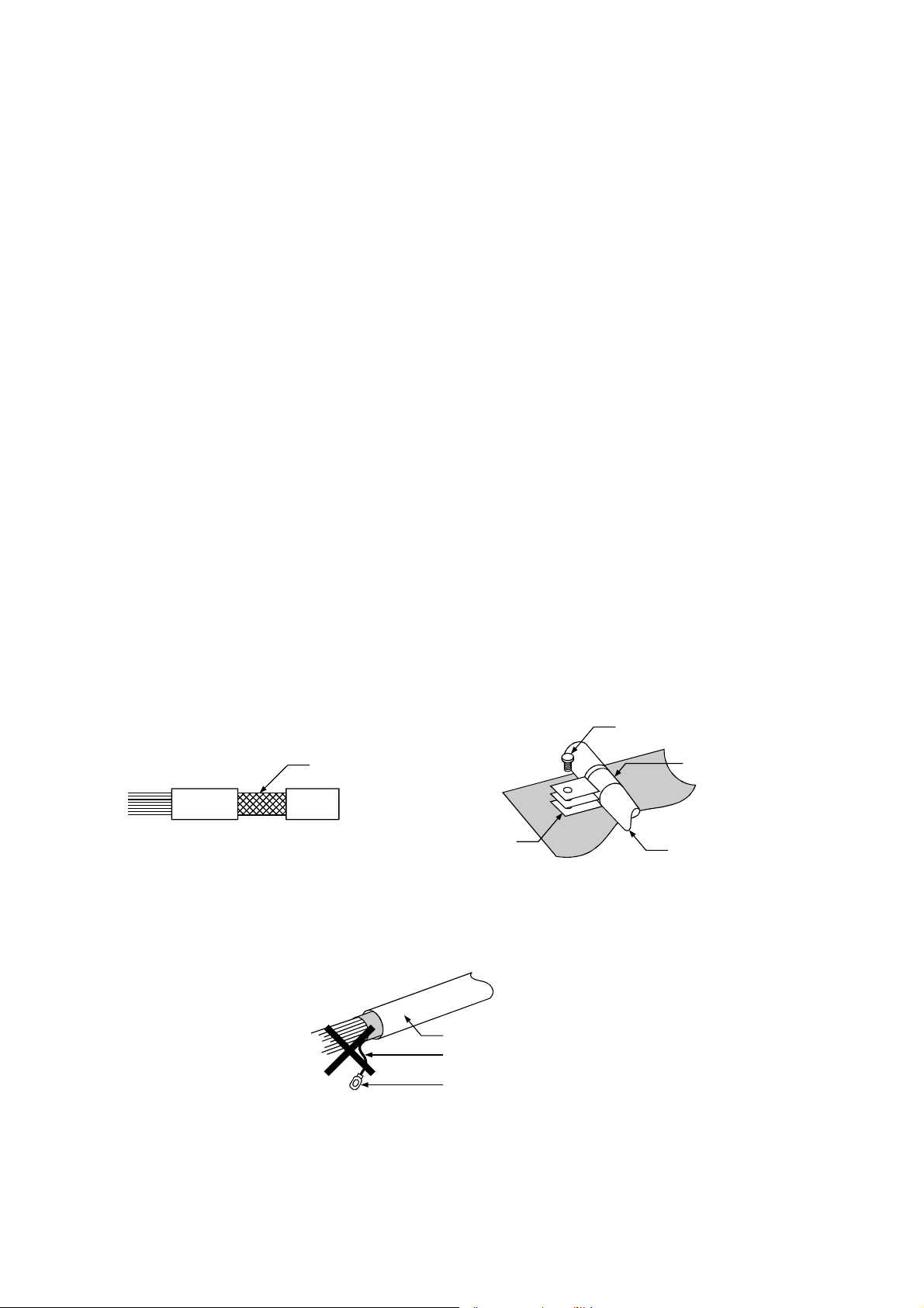
(b) Take appropriate measures so that the shield section of the shielded
cable from which the outer cover was partly removed for exposure is
earthed to the control panel on an increased contact surface. A clamp
may also be used as shown in the figure below. In this case, however,
apply a cover to the painted inner wall surface of the control panel which
comes in contact with the clamp.
Screw
Shield sectio
Clamp fitting
Paint mask
Shielded cable
Note) The method of earthing by soldering a wire onto the shield section of
the shielded cable as shown below is not recommended. The high
frequency impedance will increase and the shield will be ineffective.
Shielded cable
Wire
Crimp terminal
6
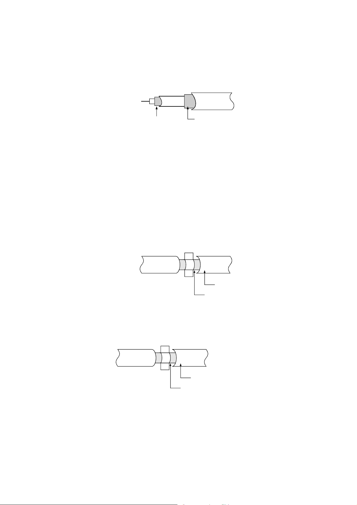
(2) MELSECNET (II) and MELSECNET/10 units
(a) Use a double-shielded coaxial cable for the MELSECNET unit which
uses coaxial cables. Noise in the range of 30 MHz or higher in radiation
noise can be suppressed by the use of double-shielded coaxial cables
(Mitsubishi Cable: 5C-2V-CCY). Earth the outer shield to the ground.
The precautions on shielding to be followed are the same as those
stated in item (1) above.
Earth this sectionShield
(b) Ensure to attach a ferrite core to the double-shielded coaxial cable
connected to the MELSECNET unit. In addition, position the ferrite core
on each cable near the outlet of the control panel. TDK-make ZCAT3035
ferrite core is recommended.
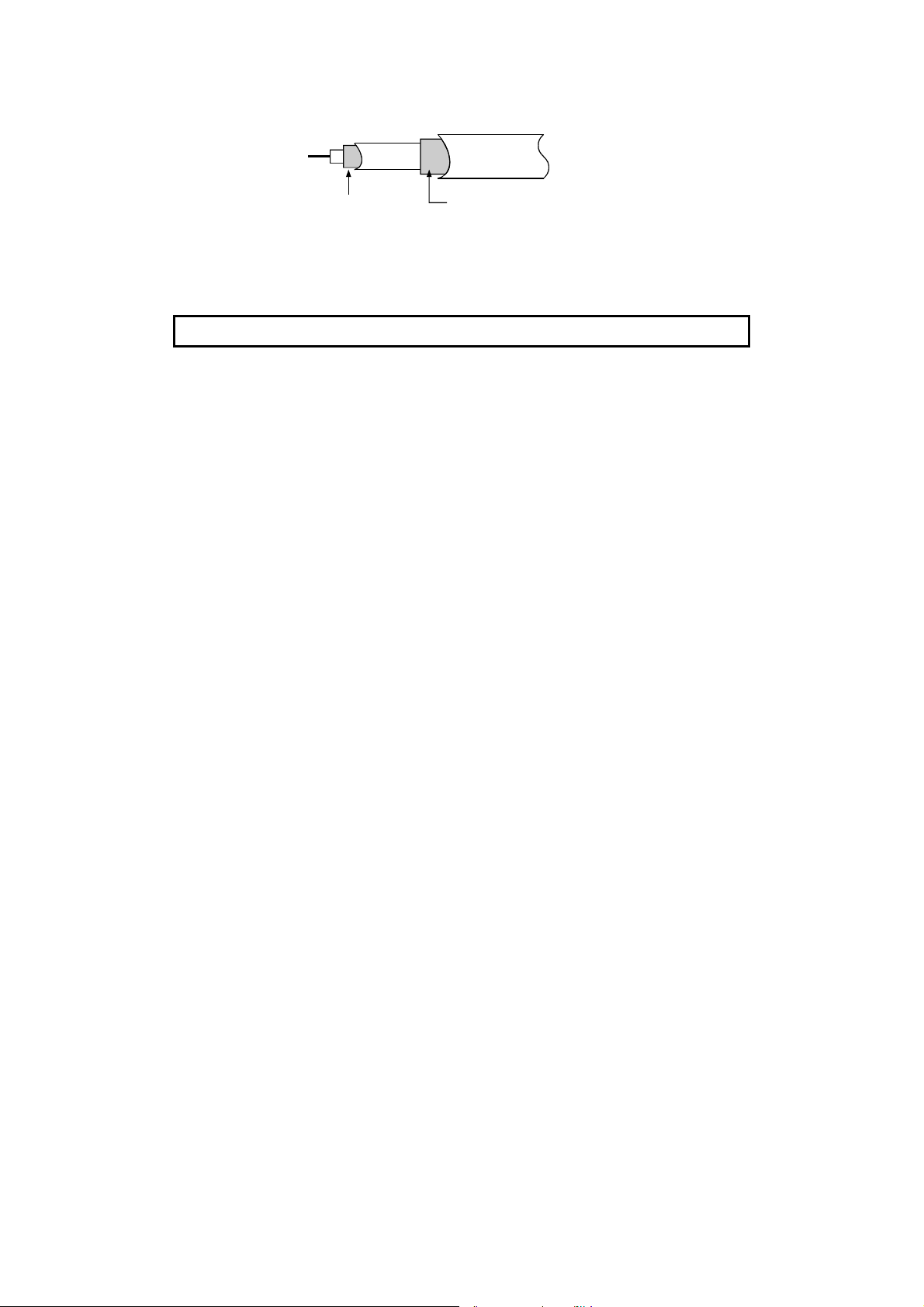
(3) Ethernet module
Precautions to be followed when AUI cables and coaxial cables are used
are described below.
(a) Ensure to earth also the AUI cables connected to the 10BASE5
connectors of the A1SJ71QE71-B5. Because the AUI cable is of the
shielded type, as shown in the figure below, partly remove the outer
cover of it, and earth the exposed shield section to the ground on the
widest contact surface.
AUI cable
Shield
(b) Use shielded twisted pair cables as the twisted pair cables*1 connected
to the 10BASE-T connectors. For the shielded twisted pair cables, strip
part of the outer cover and earth the exposed shield section to the
ground on the widest contact surface as shown below.
Shielded twisted pair cables
Shield
Refer to (1) for the earthing of the shield.
*1: Make sure to install a ferrite core for the cable.
As a ferrite core, ZCAT2035 manufactured by TDK is recommended.
7
(c) Always use double-shielded coaxial cables as the coaxial cables*2
connected to the 10BASE2 connectors. Earth the double-shielded
coaxial cable by connecting its outer shield to the ground.
Earth hereShield
Refer to (1) for the earthing of the shield.
*2: Make sure to install a ferrite core for the cable.
As a ferrite core, ZCAT2035 manufactured by TDK is recommended.
Ethernet is the registered trademark of XEROX, Co.,LTD
(4) I/O and other communication cables
For the I/O signal lines (including common line) and other communication
cables (RS-232, RS-422, etc), if extracted to the outside of the control panel,
also ensure to earth the shield section of these lines and cables in the same
manner as in item (1) above.
8
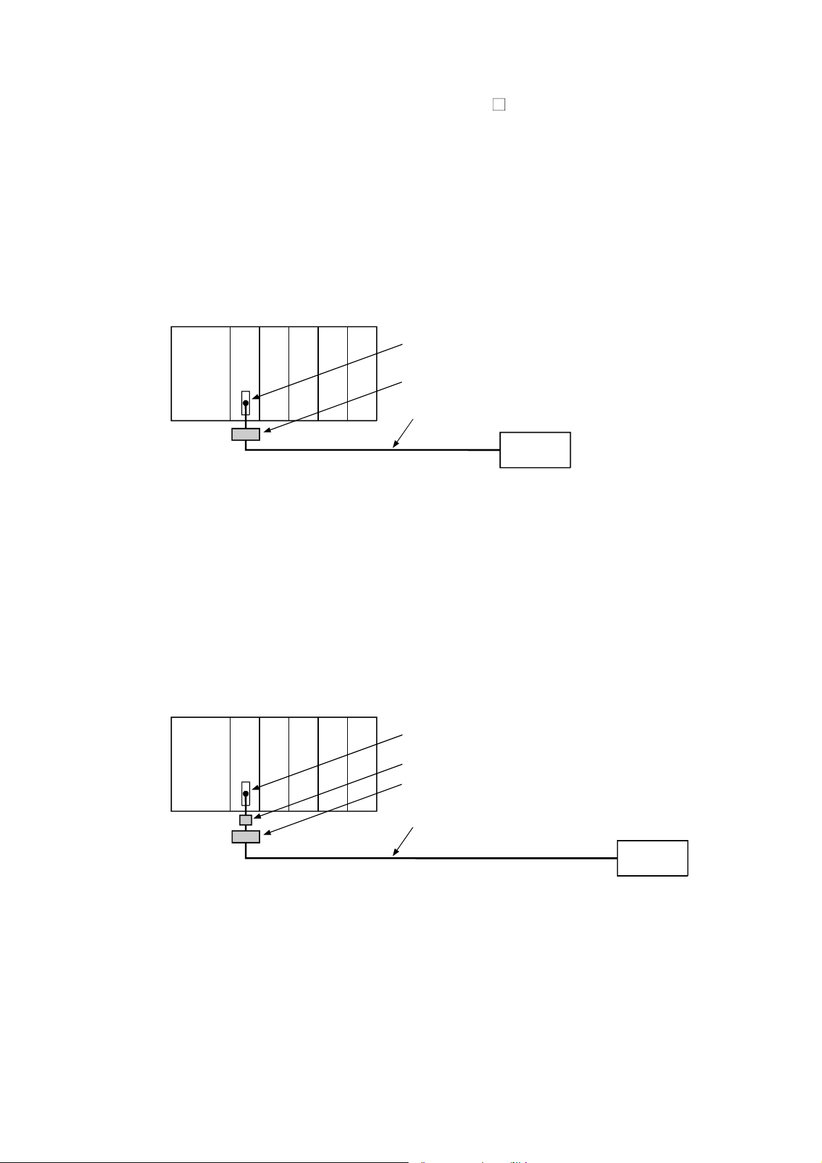
(5) Positioning Modules
Precautions to be followed when the machinery conforming to the EMC
Directive is configured using the A1SD75P
-S3 are described below.
(a) When wiring with a 2 m (6.56 ft.) or less cable
• Ground the shield section of the external wiring cable with the cable
clamp.
(Ground the shield at the closest location to the A1SD75 external
wiring connector.)
• Wire the external wiring cable to the drive unit and external device with
the shortest practicable length of cable.
• Install the drive unit in the same panel.
e
l
5
u
d
o
m
U
P
C
e
l
7
u
D
d
S
o
1
m
A
External wiring connector
Cable clamp
External wiring cable (within 2 m (6.56 ft.))
Drive unit
(b) When wiring with cable that exceeds 2 m (6.56 ft.), but is 10 m (32.81 ft.)
or less
• Ground the shield section of the external wiring cable with the cable
clamp.
(Ground the shield at the closest location to the A1SD75 external
wiring connector.)
• Install a ferrite core.
• Wire the external wiring cable to the drive unit and external device with
the shortest practicable length of cable.
e
l
5
u
d
o
m
U
P
C
e
7
l
u
D
d
S
o
1
m
A
External wiring connector
Ferrite core
Cable clamp
External wiring cable (2 m to 10 m (6.56 ft. to 32.81 ft.))
Drive unit
9
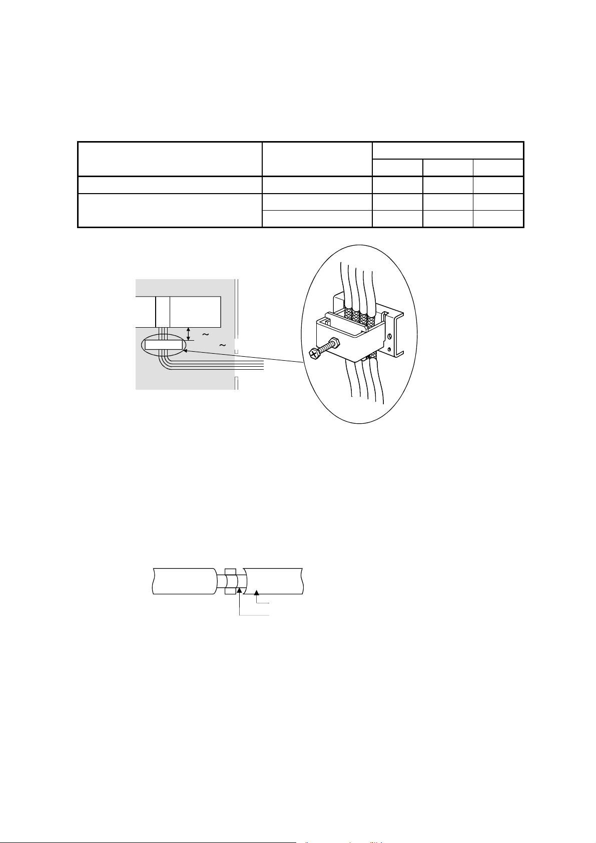
(c) Ferrite core and cable clamp types and required quantities
• Cable clamp
Type : AD75CK (Mitsubishi Electric)
• Ferrite core
Type : ZCAT3035-1330 (TDK ferrite core)
• Required quantity
Cable length Prepared part
Within 2 m (6.56 ft.) AD75CK 1 1 1
2 m (6.56 ft.) to 10m (32.81 ft.)
Inside control panel
A1SD75
20 30cm
AD75CK
(7.87 11.81inch)
AD75CK 1 1 1
ZCAT3035-1330 1 2 3
1 axis 2 axes 3 axes
Required Qty
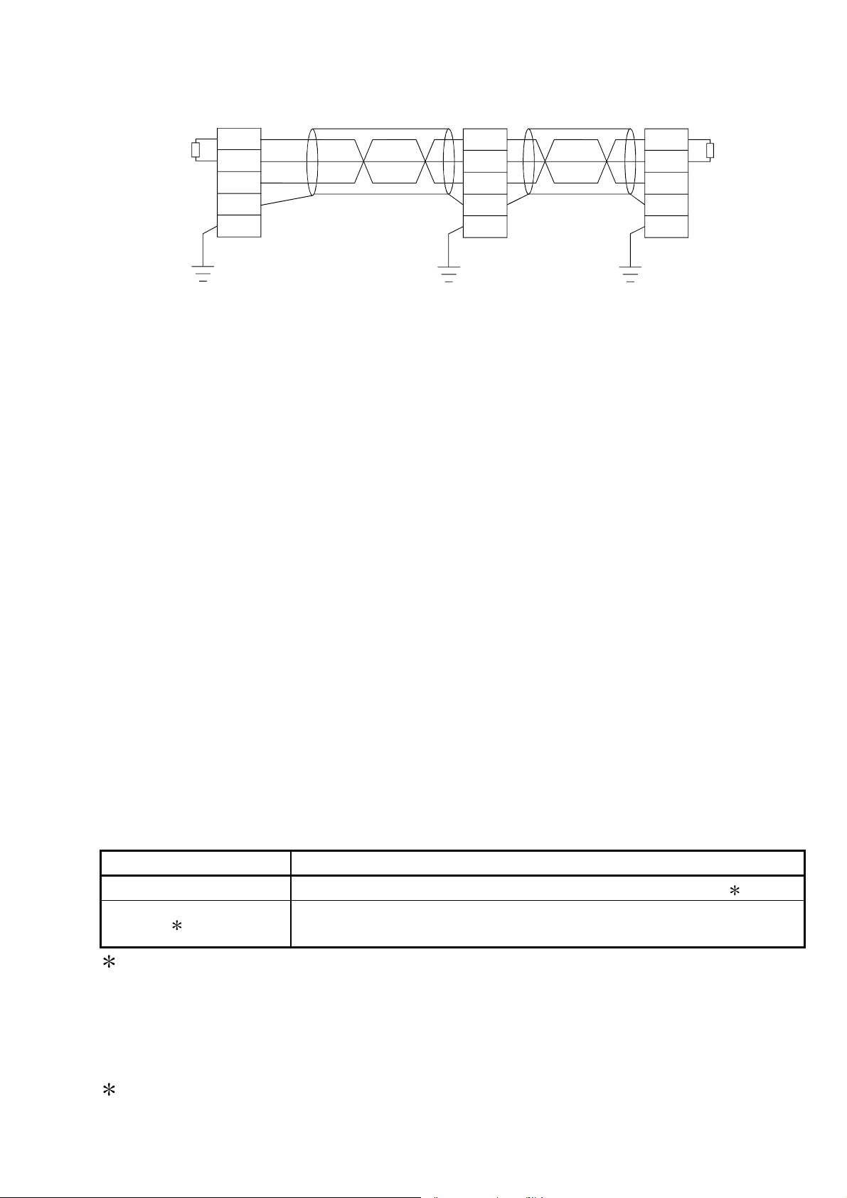
(6) CC-Link Module
(a) Be sure to ground the cable shield that is connected to the CC-Link
module close to the exit of control panel or to any of the CC-Link stations
within 30 cm (11.81 in.) from the module or stations.
The CC-Link dedicated cable is a shielded cable. As shown in the
illustration below, remove a portion of the outer covering and ground as
large a surface area of the exposed shield part as possible.
CC-Link dedicated cable
Shield
(b) Always use the specified CC-Link dedicated cable.
(c) The CC-Link module, the CC-Link stations and the FG line inside the
control panel should be connected at both the FG terminal and the SLD
terminal as shown in the diagram below.
10
[Simplified diagram]
Local module
DA
DB
Terminal
DG
SLD
resistor
FG
Terminal
resistor
Master module
(Blue)
DA
(White)
DB
(Yellow)
DG
SLD
FG
CC-Link
dedicated
cable
Remote module
DA
DB
DG
SLD
FG
CC-Link
dedicated
cable
(d) Power line connecting to the external power supply terminal (compliant
with I/O power port of CE standard) should be 30m (98.43 ft.) or less.
Power line connecting to module power supply terminal (compliant with
main power port of CE standard) should be 10m (32.81 ft.) or less.
(e) A power line connecting to the analog input of the following modules
should be 30cm or less.
• AJ65BT-64RD3
• AJ65BT-64RD4
• AJ65BT-68TD
(7) Measures against static electricity
When using an insulation displacement connector without connector cover,
a connected cable for the connector is thin in applicable wire size and
coating. Therefore, note that the module may cause an electric discharge
failure.
As measures against the failure, using pressure-displacement type
connector whose applicable wire size is thick or soldering type connector is
recommended.
3.1.4 Power supply module
The precautions required for each power supply module are described below.
Always observe the items noted as precautions.
Model Precautions
A1S61PN, A1S62PN Make sure to short and ground the LG and FG terminals. 2
A1S63P 10
Use the 24VDC panel power equipment conforming to the EU
Directive.
1: If sufficient filter circuitry is built into the 24 VDC external power supply
module, the noise generated by A1S63P will be absorbed by that filter
circuit, so a line filter may not be required.
Filtering circuitry of version F or later of A1S63P is improved so that a
external line filter is not required.
2: To ensure the compliance with CE (EN6111-21/A11), make sure to short
the LG and FG terminals using a wire of 6 to 7cm.
11

3.1.5 Ferrite core
A ferrite core has the effect of reducing radiated noise in the 30 M Hz to 100 M
Hz band. With the exception of some models, it is not required to fit ferrite
cores to cables, but it is recommended to fit ferrite cores if shield cables pulled
out of the enclosure do not provide sufficient shielding effects.*1 The ferrite
cores used in our tests are TDK's ZCAT3035.
It should be noted that the ferrite cores should be fitted to the cables in the
position immediately before they are pulled out of the enclosure. If the fitting
position is improper, the ferrite will not produce any effect.
1:To response with CE(EN61131-2/A12), make sure to mount 2 or more
ferrite cores onto the power supply line. The mounting position should be as
near the power supply module as possible.
Ferrite core
Type: ZCAT2235-1030A (TDK ferrite core)
12
3.1.6 Noise filter (power supply line filter)
A noise filter is a component which has an effect on conducted noise. With the
exception of some models, it is not required to fit the noise filter to the power
supply line, but fitting it can further suppress noise. (The noise filter has the
effect of reducing conducted noise of 10 M Hz or less.) Use any of the following
noise filters (double
Model name FN343-3/01 FN660-6/06 ZHC2203-11
Manufacturer SCHAFFNER SCHAFFNER TDK
Rated current 3 A 6 A 3 A
Rated voltage 250 V
type filters) or equivalent.
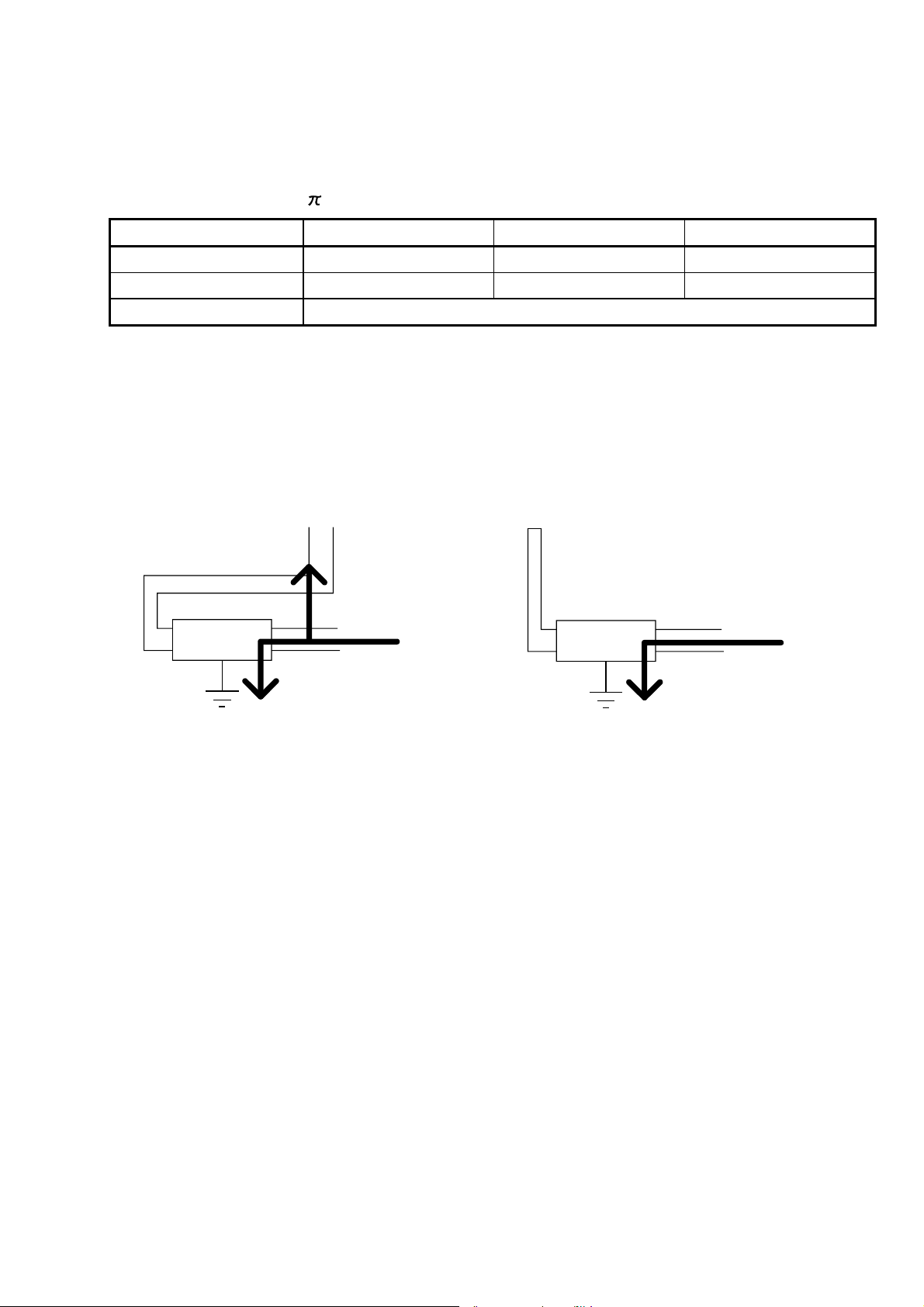
The precautions required when installing a noise filter are described below.
(1) Do not bundle the wires on the input side and output side of the noise filter.
When bundled, the output side noise will be induced into the input side
wires from which the noise was filtered.
Input side
(power supply side)
Induction
Filter
Input side
(power supply side)
Filter
Output side
(device side)
Output side
(device side)
(a) The noise will be
included when the input
(b) Separate and lay the
input and output wires.
and output wires are
bundled.
(2) Earth the noise filter earthing terminal to the control cabinet with the
shortest wire possible (approx. 10 cm (3.94 in.)).
3.1.7 Power line for external power supply terminal
The power line connecting to the external power supply terminal of the module
should be 30m (98.43 ft.) or less.
13
 Loading...