

Page 1
PROFIBUS-DP Interface Module
Type AJ71PB92D/A1SJ71PB92D
User,s Manual
Mitsubishi Programmable Logic Controller
Page 2

Page 3
SAFETY PRECAUTIONS
(Read these precautions before using.)
When using Mitsubishi equipment, thoroughly read this manual and the associated manuals introduced
in this manual. Also pay careful attention to safety and handle the module properly.
These precautions apply only to Mitsubishi equipment. Refer to the CPU module user’s manual for a
description of the PLC system safety precautions.
These • SAFETY PRECAUTIONS • classify the safety precautions into two categories: “DANGER” and
“CAUTION”.
DANGER
Procedures which may lead to a dangerous condition and cause death or
serious injury if not carried out properly.
CAUTION
Procedures which may lead to a dangerous condition and cause superficial
to medium injury, or physical damage only, if not carried out properly.
Depending on circumstances, procedures indicated by
CAUTION may also be linked to serious results.
In any case, it is important to follow the directions for usage.
Store this manual in a safe place so that you can take it out and read it whenever necessary. Always
forward it to the end user.
[DESIGN PRECAUTIONS]
DANGER
z
When a communication error occurs in the PROFIBUS network, the status of the faulty station is as follows.
Configure an interlock circuit in the sequence program using the communication status information (input
X1, buffer memory 2040 to 2079) so that the system can operate safely.
Erroneous outputs and mis-operation could cause accidents.
(1) The input data of the master station maintains the data before abnormality of the communication.
(2) When the master station is down, the output state of each slave station will be in accordance with the
parameter settings.
(3) When any slave station is down, the output state of other slave stations will be in accordance with the
parameter settings of the master station.
z
If a stop error occurs in the CPU module, the communication status is as described below.
(1) Communication with the slave station is stopped.
(2) For the input data received from the slave station, the values at CPU module stop error occurrence are
held.
(3) The output data sent from the AJ71PB92D/A1SJ71PB92D to the slave station are cleared.
CAUTION
z
When the PROFIBUS cable is laid, do not lay it close to main circuits or power lines.
They should be installed 100mm(3.9inch) or more from each other.
Not doing so could result in noise that would cause malfunctioning.
Page 4
[INSTALLATION PRECAUTIONS]
CAUTION
z
Use the module in the environment given in the general specifications of the CPU module’s User’s Manual.
Using the module outside the range of the general specifications may result in electric shock, fire or
malfunctioning, or may damage or degrade the module.
z
Insert the tabs at the bottom of the module into the mounting holes in the base unit before installing the
module. (The AnS series module shall be fastened by screws in the base unit at the specified torque.)
Not installing the module correctly could result in malfunctioning, breakdowns or pieces of the product falling
z
Tighten the fixing screws of the PROFIBUS cable with the specified torque. If the screws are loose, it could
result in malfunction of the module.
z
Do not touch the conductive area or electric parts of the module.
Doing so may cause module malfunctioning or breakdowns.
[WIRING PRECAUTIONS]
CAUTION
z
Switch all phases of the external power supply of the PLC system off before connecting the PROFIBUS
cable. Not doing so could cause failure or malfunctioning of the module.
z
Be careful not to let foreign matter such as filings or wire chips get inside the module. These can cause fire,
breakdowns and malfunctioning.
z
The PROFIBUS cable which is connected to the module must be protected with a duct or secured in
position with clamps.
Unless the cable is thus protected or secured, the module or the cable could be damaged when the cable
swings, moves or it is strained with careless pulls, or it could cause malfunction when the cable contacts
with any undesirable objects.
z
When disconnecting the PROFIBUS cable from the module, do not pull by holding the cable section. To
disconnect the cable, make sure to hold the connector which is coupled with the module. Do not attempt to
pull the cable to disconnect it from the module. It could damage the module or the cable, or cause
malfunction due to a poor contact of the cable.
[STARTING AND MAINTENANCE PRECAUTIONS]
DANGER
z
Switch all phases of the external power supply off before cleaning.
Not doing so could cause electric shock.
Page 5
CAUTION
z
Never disassemble or modify the module.
This may cause breakdowns, malfunctioning, injury and/or fire.
z
Switch all phases of the external power supply off before mounting or removing the module. If you do not
switch off the external power supply, it will cause breakdowns or malfunction of the module.
z
Set the ON/OFF select switch of the terminal resistor before the operation.
If the setting is switched during the operation, network error may occur, or error detection may not be
performed by error.
z
Before handling the module, always touch grounded metal, etc. to discharge static electricity from the
human body.
Failure to do so can cause the module to fail or malfunction.
[OPERATING PRECAUTIONS]
DANGER
z
Do not write data into the "not usable" of the buffer memory of special function modules. Also, do not output
the "not usable" signal as the output signal to a special function module from the PLC CPU. Writing data
into the "not usable area" or outputting an "not usable" signal may cause system malfunctions in the PLC.
CAUTION
z
The online operations conducted for the CPU module being operated (especially when changing data or
operation status), shall be conducted after the manual has been carefully read and a sufficient check of
safety has been conducted.
Operation mistakes could cause breakdowns to or malfunction of the module.
[DISPOSAL PRECAUTIONS]
CAUTION
z
When disposing of this product, treat it as industrial waste.
Page 6
Revisions
* The manual number is noted at the lower left of the back cover.
Print Date *Manual Number Revision
May, 1997 IB (NA)-66773-A First printing
Sep., 1997 IB (NA)-66773-B Correction
Section 2.3, Chapter 3
Addition
Appendix 2
Oct., 1998 IB (NA)-66773-C Model Addition
AJ71PB92D
Correction
SAFTY PRECAUTIONS, Chapter 1, 2, 3, 4, Section 5.1, 5.2, 5.3, 5.5.1,
5.5.2, 5.6, 6.1, Chapter 7, 8, 9
Addition
Appendix 1
Chapter Alteration
Appendix 1 → Appendix 3
Jun., 2000 IB (NA)-66773-D Correction
Chapter 1, Section 2.1, 2.2, 2.3, 2.4, 2.5, 3.1, 3.2, 4.2.1, 4.2.2, 4.3.1, 5.5.1,
Appendix 1
Addition
Section 2.6, 4.4, 4.5, 8.6
Jun., 2003 IB (NA)-66773-E Correction
SAFTY PRECAUTIONS, Section 4.3.2, 6.1, 8.2.1, 8.2.2
Addition
Section 3.3.3, Appendix 2
Apr., 2004 IB (NA)-66773-F Correction
Section 1.2, 3.2, 3.3.3, 4.2.2, 4.3.1, 4.3.2, 4.6, 5.1, 5.3, 6.1, 6.2
Addition
SAFTY PRECAUTIONS, Chapter 9
Aug., 2004 IB (NA)-66773-G Correction
SAFTY PRECAUTIONS, Section 2.2, 3.3.2, 3.3.3, 4.3.2, 5.5.1, Chapter 8,
Section 8.2.2
Japanese Manual Version SH-3330-G
This manual does not imply guarantee or implementation right for industrial ownership or implementation
of other rights. Mitsubishi Electric Corporation is not responsible for industrial ownership problems caused
by use of the contents of this manual.
1998 Mitsubishi Electric Corporation
Page 7

Introduction
Thank you for purchasing the Mitsubishi Programmable Controller MELSEC-A Series.
Before using the equipment, plese read this manual carefully to develop full familiarity with the functions and
performance of the graphic operation terminal you have purchased, so as to ensure correct use.
Please forward a copy of this manual to the end user.
Table of Contents
About This Manual
1. OVERVIEW 1-1 to 1-2
1.1 Software Configuration......................................................................................................................................1- 1
1.2 AJ71PB92D/A1SJ71PB92D Features .............................................................................................................1- 2
2. SYSTEM CONFIGURATION 2-1 to 2-6
2.1 Whole System Configuration ............................................................................................................................2- 1
2.2 System Configuration Example.........................................................................................................................2- 2
2.3 Applicable CPU Modules..................................................................................................................................2- 3
2.4 Installable Base Units .......................................................................................................................................2- 4
2.5 Combining with MELSECNET (II), MELSECNET/B, and MELSECNET/10.......................................................2- 4
2.6 Precautions for Configuring a System ..............................................................................................................2- 5
3. SPECIFICATIONS 3-1 to 3-10
3.1 General Specification........................................................................................................................................3- 1
3.2 Performance Specifications..............................................................................................................................3- 2
3.3 Network Configuration.......................................................................................................................................3- 3
3.3.1 Basic configuration................................................................................................................................3- 3
3.3.2 Applicable configuration.........................................................................................................................3- 4
3.3.3 Number of connectable slaves..............................................................................................................3- 8
4. FUNCTIONS 4-1 to 4-32
4.1 Functions for Exchanging with Slaves..............................................................................................................4- 1
4.1.1 Exchange flow........................................................................................................................................4- 1
4.1.2 Global control functions.........................................................................................................................4- 2
4.2 I/O Signal..........................................................................................................................................................4- 5
4.2.1 I/O signal list..........................................................................................................................................4- 5
4.2.2 I/O signal detail description....................................................................................................................4- 6
4.3 Buffer Memory List............................................................................................................................................4- 9
4.3.1 Buffer memory/configuration..................................................................................................................4- 9
4.3.2 Buffer memory detailed description.......................................................................................................4-10
4.4 While-Run Operation Mode Changing Function...............................................................................................4-30
4.5 AJ71PB92D/A1SJ71PB92D's Remote Parameter Setting Function Using MELSEC ProfiMap
Configuration Software......................................................................................................................................4-31
4.6 E
2
PROM initialization function..........................................................................................................................4-32
5. PROCEDURES BEFORE SYSTEM OPERATION 5-1 to 5-10
5.1 Procedures before Operation............................................................................................................................5- 1
5.1.1 Parameter setting procedure.................................................................................................................5- 2
5.2 Handling Precautions ........................................................................................................................................5- 3
5.3 Part Names and Settings..................................................................................................................................5- 4
Page 8

5.4 Execution Method for Self-diagnosis.................................................................................................................5- 6
5.5 Wiring................................................................................................................................................................5- 7
5.5.1 PROFIBUS cable wiring.........................................................................................................................5- 7
5.5.2 Terminator switch ..................................................................................................................................5- 7
5.5.3 Precautions against wiring.....................................................................................................................5- 8
5.6 Maintenance and Inspection.............................................................................................................................5-10
6. COMMUNICATION TIME 6-1 to 6-4
6.1 Transmission Delay Time When There is One Master Station.........................................................................6- 1
6.2 Transmission Delay Time When There are Multiple Master Stations...............................................................6- 4
7. DDB FILE 7-1 to 7-2
8. PROGRAMMING 8-1 to 8-6
8.1 Initial Program...................................................................................................................................................8- 1
8.2 Data I/O with Slave...........................................................................................................................................8- 2
8.2.1 Normal service mode (MODE switch : No. 0)........................................................................................8- 2
8.2.2 Extend service mode (MODE switch : No. E)........................................................................................8- 3
8.3 Communication Trouble Area and Expansion Communication Trouble Area Clear.........................................8- 4
8.4 Address Information Read................................................................................................................................8- 4
8.5 Global Control...................................................................................................................................................8- 5
8.6 While-Run Operation Mode Changing..............................................................................................................8- 6
9. TROUBLESHOOTING 9-1 to 9-2
APPENDIX A-1 to A-10
Appendix 1 Differences between AJ71PB92D/A1SJ71PB92D Software Versions................................................. A- 1
Appendix 1.1 Differences between A1SJ71PB92D Software Versions...........................................................A- 1
Appendix 1.2 Restrictions on Use of A1SJ71PB92D Software Versions in the Same System....................... A- 2
Appendix 1.3 Differences between AJ71PB92D Software Versions...............................................................A- 2
Appendix 1.4 Restrictions on Use of AJ71PB92D Software Versions in the Same System ...........................A- 2
Appendix 2 Precautions for Replacing AJ71PB92 with A(1S)J71PB92D................................................................A- 3
Appendix 3 Extended Trouble Information of Mitsubishi's Slaves...........................................................................A- 7
Appendix 4 External Dimensions.............................................................................................................................A- 8
Page 9
About This Manual
The following are manuals related to this product.
Request for the manuals as needed according to the chart below.
Related Manual
Manual Name Article No.
MELSEC ProfiMap Configuration System for Open Networks Software Manual 65778-B
* Inquiries can be made to :
MITSUBISHI ELECTRIC EUROPE Factory Automation
Gothaer Strasse 8 D-40880 Ratingen Germany
Phone : +49(21 02)486-0
Fax : +49(21 02)486-717
Page 10
1. OVERVIEW MELSEC-A
1-1
1. OVERVIEW
This is the user's manual for the AJ71PB92D/A1SJ71PB92D PROFIBUS-DP interface module
(hereafter abbreviated as " AJ71PB92D/A1SJ71PB92D. When explain separately, however,
abbreviated as AJ71PB92D, A1SJ71PB92D), which is used to connect a MELSEC-A/QnA/Q series
programmable controller to a PROFIBUS-DP network.
The AJ71PB92D/A1SJ71PB92D operates as a master station (class 1) in the PROFIBUS-DP network.
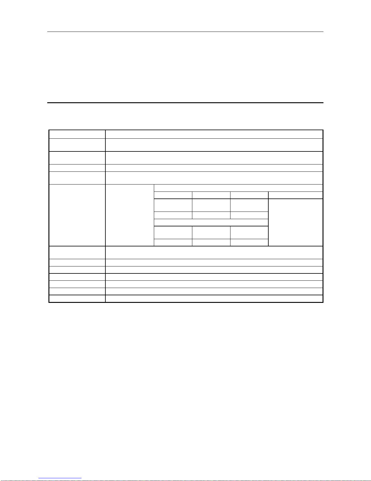
1.1 Software Configuration
FROM/TO
User Interface
Direct Data Link Mapper
FDL
PHY
(DDLM)
empty
FMA1/2
MELSEC A Series PC
Communication using a buffer memory
Portion where master
PCB is installed
Layer 3 to 7
Layer 2 Datalink layer
Layer 1 Physical layer
Portion where slave
PCB is installed
The AJ71PB92D/A1SJ71PB92D has a physical layer, data link layer, DDLM, and user interface that
conform to PROFIBUS-DP, and communicates data with the PLC CPU by using a buffer memory.
The main application of PROFIBUS-DP is networks that execute high-speed communication at the
level of sensors and actuators, and the AJ71PB92D/A1SJ71PB92D has been designed with this in
mind: its functions are mainly related to data I/O with slave stations.
Page 11

1. OVERVIEW MELSEC-A
1-2
1.2 AJ71PB92D/A1SJ71PB92D Features
(1) Operates as a PROFIBUS-DP master (class 1) station.
(2) Makes possible the exchange of input and output data to and from the slave station
without the need to be aware of the PROFIBUS-DP protocol by using I/O signals X/Y and
the buffer memory.
(3) Supports 3M, 6M, 12M [bps] network communication speeds in addition to the 9.6k, 19.2k,
93.75k, 187.5k, 500k, and 1.5M [bps] supported by the AJ71PB92D/A1SJ71PB92D. These
can be selected using a configurator.
(4) Station Nos. from 0 to 125 can be set using the configurator.
(5) Trouble information can be read from the slave station using the I/O signal X/Y and the
buffer memory.
(6) The global control function makes it possible to maintain all slave I/O at the same time. In
addition, this can also be canceled.
(7) The module contains a self-diagnosis function that can be used to test the hardware such
as the internal memory.
Page 12
2. SYSTEM CONFIGURATION MELSEC-A
2-1
2. SYSTEM CONFIGURATION
This section explains system configuration for the AJ71PB92D/A1SJ71PB92D
2.1 Whole System Configuration
(1) For the A1SJCPU
A1SJCPU (S3)
Extension cable
Extension base unit
A1SJ71PB92D
A1SC[ ]B
A1S6[ ]B(S1)/A1S5[ ]B(S1)
A1SJHCPU
(2) For the compact building block type CPU
Compact building block type
CPU
Extension cable
A1SC[ ]B
Extension base unit
Basic base unit
A1SJ71PB92D
A1S6[ ]B(S1)/A1S5[ ]B(S1)
A1S3[ ]B/A1S38HB
(3) For the building block type CPU
Building block type CPU
Extension cable
AC[ ]B
Extension base unit
Basic base unit
AJ71PB92D
A6[ ]B/A5[ ]B
A3[ ]B/A38HB
Page 13
2. SYSTEM CONFIGURATION MELSEC-A
2-2
(4) For the Q series CPU
Q series CPU
Extension cable
QC[ ]B
Extension base unit
Basic base unit
A1SJ71PB92D
QA1S6[ ]B
Q3[ ]B
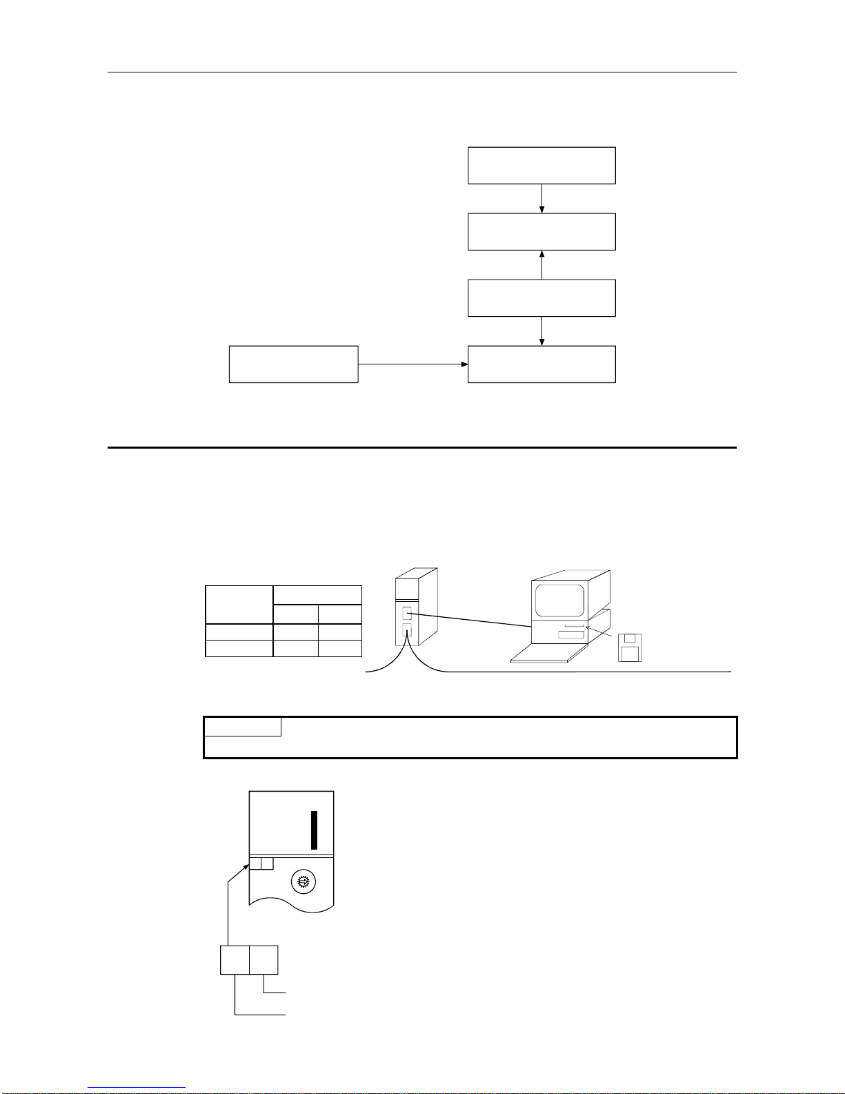
2.2 System Configuration Example
The following describes the A1SJ71PB92D system configuration example.
A communication parameter file is created in Windows using the Configurator software package, this
parameter file can then be down-loaded via an RS-232C cable to the AJ71PB92D/A1SJ71PB92D.
Via RS-232C
AJ71PB92D
A1SJ71PB92D
RS-232C
Personal computer supporting Window s 3.1 or 95
MITSUBISHI ELECTR IC Corp.
MELSEC ProfiMap
(Ver. 3.0 or later)
PROFIBUS network
Point
Refer to "About This Manual" for inquiry for MELSEC ProfiMap.
*: Version confirmation method of AJ71PB92D/A1SJ71PB92D
0
F
E
D
C
B
A
9
8
7
6
5
4
3
2
1
MODE
0:ONLINE 1
1:PRM SET
2:TEST
A1SJ71PB92D
RUN
SD/RD
TOKEN
READY
FROM/TO
PRM SET
RSP ERR.
FAULT
TEST
B6
B5
B4
B3
B2
B1
B0
S
T
.
N
O
.
BG
BG
Software version
Hardware version
E:ONLINE 2
Version
Hardware Software
AJ71PB92D
A or later C or later
A1SJ71PB92D B or later G or later
Model
Page 14
2. SYSTEM CONFIGURATION MELSEC-A
2-3
2.3 Applicable CPU Modules
The following table shows the CPUs that the AJ71PB92D/A1SJ71PB92D can use.
(1) AJ71PB92D
Applicable CPU Modules
A1SCPUC24-R2
A1SJHCPU, A1SHCPU,
A2SHCPU, A2SHCPU-S1 ,
A1NCPU, A1NCPUP21,
A1NCPUP21-S3, A1 NCP UR2 1 ,
A2NCPU, A2NCPUP21,
A2NCPUP21-S3, A2 NCP UR2 1 ,
A2NCPU-S1, A2NCPUP2 1 - S 1 ,
A2NCPUP21-S4, A2 NCP UR2 1 ,
A3NCPU, A3NCPUP21,
A3NCPUP21-S3, A3 NCP UR2 1
A2ASCPU, A2ASCPU-S1,
A2ASCPU-S30, A2USHCPU-S1
A2ACPU, A2ACPUP21,
A2ACPUP21-S3, A2ACPUR21,
A2ACPU-S1, A2ACPUP21-S1,
A2ACPUP21-S4, A2ACPUR21,
A3ACPU, A3ACPUP21,
A3ACPUP21-S3, A3ACPUR21,
A2UCPU,A2UCPU-S1,
A3UCPU, A4UCPU
Q2ASCPU, Q2ASCPU-S1,
Q2ASHCPU, Q2ASHCPU- S 1 ,
Q2ACPU, Q2ACPU-S1,
Q3ACPU, Q4ACPU, Q4ARCPU
(2) A1SJ71PB92D
Applicable CPU Modules
A1SCPUC24-R2
A1SJHCPU, A1SHCPU,
A2SHCPU, A2SHCPU-S1
A2ASCPU, A2ASCPU-S1,
A2ASCPU-S30, A2USHCPU-S1
Q2ASCPU, Q2ASCPU-S1,
Q2ASHCPU, Q2ASHCPU- S 1
Q02CPU-A, Q02HCPU-A,
Q06HCPU-A
Page 15
2. SYSTEM CONFIGURATION MELSEC-A
2-4
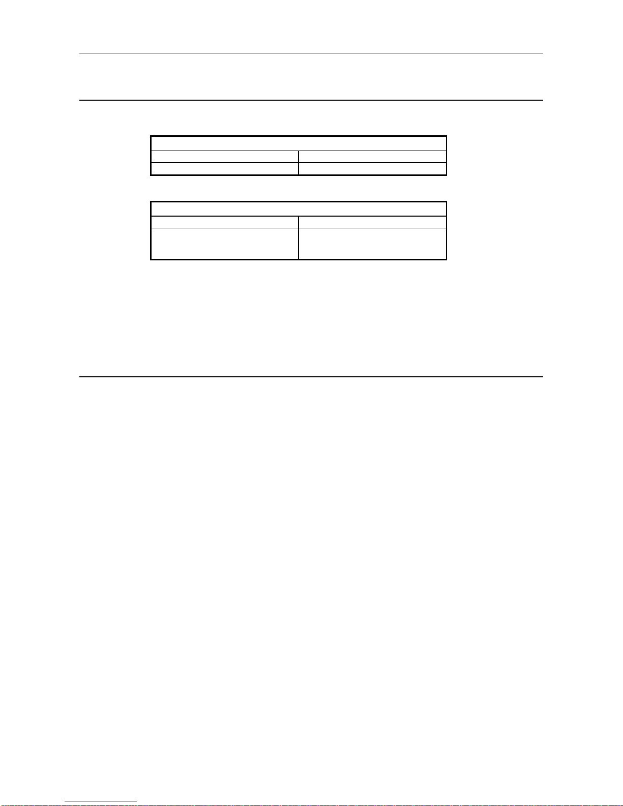
2.4 Installable Base Units
The base modules that can be installed in the AJ71PB92D/AISJ71PB92D are shown below.
(1) AJ71PB92D
Installable Base Units
Basic base unit Extension base unit
A32B, A32B-S1, A35B, A38B, A38HB A52B, A55B, A58B, A62B, A65B, A68B
(2) A1SJ71PB92D
Installable Base Units
Basic base unit Extension base unit *1
A1S32B, A1S33B, A1S35B, A1S38B,
A1S38HB
A1S52B (S1), A1S55B (S1), A1S58B (S1),
A1S65B (S1), A1S68B (S1),QA1S65B,
QA1S68B
*1: The no power supply module extension base unit A1S5 [ ] B (S1) may not have sufficient power
supply capacity, so use the A1S6 [ ] B (S1) when installing a AJ71PB92D/A1SJ71PB92D in the
extension base unit.
When the A1S5 [ ] B (S1) must be installed, do so after referring to the chapter covering power
supplies in the respective CPU Module User’s Manual.
2.5 Combining with MELSECNET (II) , MELSECNET/B, and
MELSECNET/10
The AJ71PB92D/A1SJ71PB92D can be installed in the MELSECNET (II) and MELSECNET/B master
stations and local stations, and in the MELSECNET/10 control stations and normal stations.
However, the AJ71PB92D/A1SJ71PB92D cannot be installed in the MELSECNET (II),
MELSECNET/B, and MELSECNET/10 remote stations, so be careful.
Page 16
2. SYSTEM CONFIGURATION MELSEC-A
2-5
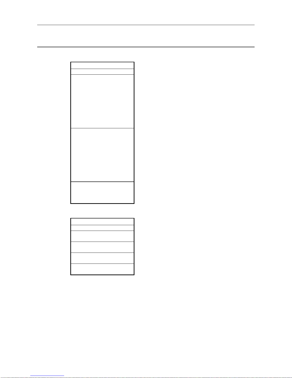
2.6 Precautions for Configuring a System
(1) There are the following restrictions on the AJ71PB92D/A1SJ71PB92D according to the
applied CPU module and used configuration software.
Parameter File Write Path Max. I/O Data Length
CPU
Module
Configuration
Software
Via
AJ71PB92D/
A1SJ71PB92D
RS-232C
interface
Via
CPU module
RS-232C/
RS-422
interface
Normal service
mode
Extended
service mode
SW0D5FPROFIMAP
32 bytes each for
input and output
MELSECPROFIMAP 2.0
Q series
CPU
MELSECPROFIMAP 3.0
244 bytes each
for input and
output*1
SW0D5FPROFIMAP
32 bytes each for
input and output
MELSECPROFIMAP 2.0
Write disabled
A/QnA
series
CPU
MELSECPROFIMAP 3.0
Write enabled
Write enabled*1
32 bytes each for
input and output
244 bytes each
for input and
output*1
*1: The software version usable by the AJ71PB92D/A1SJ71PB92D is AJ71PB92D (A or
later) or A1SJ71PB92D (E or later).
When A1SJ71PB92D (software version D or earlier) is used, write is disabled and the
max. data length is 32 bytes each for input and output.
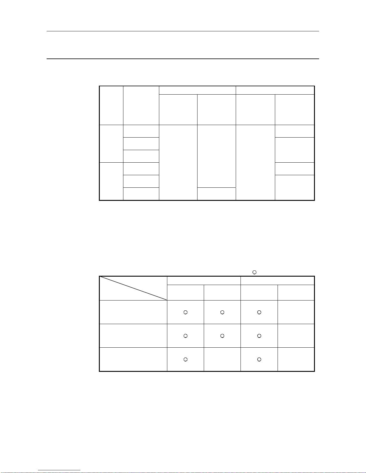
(2) Precautions for using the parameters preset for extended service mode to operate the
module in normal service mode.
The following table gives the operating conditions (conditions per one slave station) for the time
when the parameters preset for the extended service mode are used to operate the
AJ71PB92D/A1SJ71PB92D preset for the normal service mode/extended service mode.
: Operable 5 : Inoperable
Parameter Size Exchange Data LengthOperating Conditi on
AJ71PB92D
A1SJ71PB92D
122 bytes max 244 bytes max 32 bytes max 244 bytes max.
AJ71PB92D software version A
or later and normal service
mode setting
5
A1SJ71PB92D software version
E or later and normal service
mode setting
5
A1SJ71PB92D software version
D or earlier and extended
service mode setting
5 5
(3) In either of the following cases, the AJ71PB92D/A1SJ71PB92D buffer memory must be
accessed by a sequence program when the module ready signal X1D of the
AJ71PB92D/A1SJ71PB92D is ON.
• The operation mode is changed using Y11/X11 in the sequence program.
• Parameter setting is made with ProfiMap connected to other than the RS-232C port of
the AJ71PB92D/A1SJ71PB92D. (For example, parameter setting is made with ProfiMap
connected to the RS-422/RS-232 connector of the CPU module.)
If the buffer memory is accessed with the X1D status ignored, the CPU module may detect
the "SP UNIT DOWN" error, stopping the sequence operation.
Page 17

2. SYSTEM CONFIGURATION MELSEC-A
2-6
(4) Do not make parameter setting via buffer memory and parameter setting from the RS-
232C port of the AJ71PB92D/A1SJ71PB92D at the same time.
If they are made simultaneously, ProfiMap which started parameter write earlier wins the
parameter write right after the operation mode is changed to the parameter setting mode, and
the other ProfiMap cannot perform parameter write and detects an error.
This status will be automatically cleared 15 seconds after completion of parameter write if
parameter write via the CPU module is valid, or 3 seconds after completion of parameter write
if parameter write from RS-232C is valid.
(5) Do not make simultaneous access to the AJ71PB92D/A1SJ71PB92D from multiple
ProfiMap's.
If such access is made, the AJ71PB92D/A1SJ71PB92D may not be accessed properly.
(6) If remote parameter setting is performed from MELSEC ProfiMap to the
AJ71PB92D/A1SJ71PB92D which is making data exchange, note that PROFIBUS data
exchange will stop during parameter setting.
(7) In a system where remote parameter setting is made from MELSEC ProfiMap, do not
execute the mode changing function using the program.
If the mode changing function is executed in the program, an interlock with the remote
parameter setting is not provided and therefore the mode may not be changed.
Page 18
3. SPECIFICATIONS MELSEC-A
3-1
3. SPECIFICATIONS
This section explains the AJ71PB92D/A1SJ71PB92D the general specifications, performance
specifications, and transmission specifications.
3.1 General Specification
This section explains the AJ71PB92D/A1SJ71PB92D general specifications.
Table 3.1 General Specification
Item Specification
Usage environment
temperature
0 to 55
°
C
Storage environment
temperature
-20 to 75
°
C
Usage environment humidity 10 to 90%RH, No condensation formation
Storage environment
humidity
10 to 90%RH, No condensation formation
When there is intermittent vibration
Frequency Acceleration Amplitude Sweep count
10 to 57Hz —
0.075mm
(0.003in.)
Anti-vibration 57 to 150Hz 9.8m/s
2
—
Where there is continuous vibration
10 to 57Hz —
0.035mm
(0.001in.)
57 to 150Hz 4.9m/s
2
—
Anti-shock
Complies with JIS B3501, IEC61131-2
(147m/s
2
, 3 times in the direction for each of X, Y, Z)
Usage environment No corrosive gas, etc.
Usage altitude 2000m or less
Installation location Inside the control panel
Over voltage category *
1
II or less
Pollution level *
2
2 or less
Cooling method Self cooling
*1 Shows if an estimate has been made for which distribution areas the connections will be done for
the equipment from the public power grid to the equipment installation area inside the
configuration.
Category II applies to equipment that receives its power from fixed facilities. The surge
resistance voltage for equipment rated to 300V is 2500V
*2 Shows the index for inductive matter generation in the environment in which the equipment is
used. Pollution level 2 is for dirt that is non-inductive. However, occasionally inductance can be
generated in the environment by condensation.
Complies with JIS
B3501, IEC61131-2
10 times in each direction
for X, Y, Z (80 minutes)
Page 19
3. SPECIFICATIONS MELSEC-A
3-2
3.2 Performance Specifications
Item Specifications
Model AJ71PB92D A1SJ71PB92D
Electrical standards and characteristic s Complies with EIA-RS485
Medium Shielded twisted cable
Network configuration Bus (however, tree type when a repeater is used)
Data link method • Token passing method (master side)
• Polling method (master/slave side)
Transmission encoding method NRZ
Transmission speed Transmission distance [m/segm ent ]
Maximum transmission distance
when 3 repeaters are used
[m/network]
9.6 [kbps]
19.2 [kbps] 1200 4800
Transmission speed/maximum 93.75 [kbps]
transmission distance *1 *2 187.5 [kbps] 1000 4000
500 [kbps] 400 1600
1.5 [Mbps] 200 800
3 [Mbps]
6 [Mbps] 400
12 [Mbps] 100 *3
Maximum number of repeaters/network 3 units *2
Maximum number of stations/segm ent 32 stations * 3 (See "Point ")
Maximum number of slave stat ions / m as t er
station
60 slaves
Number of connection nodes (number of
repeaters)
32, 62 (1), 92 (2), 126 (3)
Transmittable data
32 bytes/1 station (Normal service mode)
244 bytes/1 station (Extemded service m ode)
Number of occupied I/O 32 points (I/O allocation : special 32 points)
5VDC Internal current consumption 0.54 A 0.56 A
Noise durability, dielectric withstand voltage
insulation resistor
Depending on the AJ71PB92D/A1SJ71PB92D installation system power supply module
specifications. (refer to the CPU Module User's Manual. )
External dimensions
250 mm (9.84 in.)(H) × 37.5 mm (1.48 in.)(W)
× 106 mm (4.17 in.)(D)
130 mm (5.12 in.)(H) × 34.5 mm (1.36 in.)(W)
× 93.6 mm (3.69 in.)(D)
Weight 0.37 kg 0.27 kg
*1 Transmission speed control within +/- 0.3% (PROFIBUS part 1)
*2 Distance that the transmission distance can be expanded by (m/network) using repeaters
Maximum transmission distance (m/network) = (number of repeaters + 1) × transmission distance (m/segment)
*3 The *3 restriction will cease to exist when the system is configured exclusively by the master and slave stations of
the hardware version B or later versions.
Point
*3 When using 12Mbps transmission speed, restriction of the cable length and the number of connector stations
described below is necessary.
1) Minimum length of the cable between stations is greater than or equal to one meter.
2) Maximum number of the connection stations are smaller than or equal to 11.
Master Slave Slave Slave Slave
2)
1)1) 1)
100
Transmission specification
s
Page 20
3. SPECIFICATIONS MELSEC-A
3-3
3.3 Network Configuration
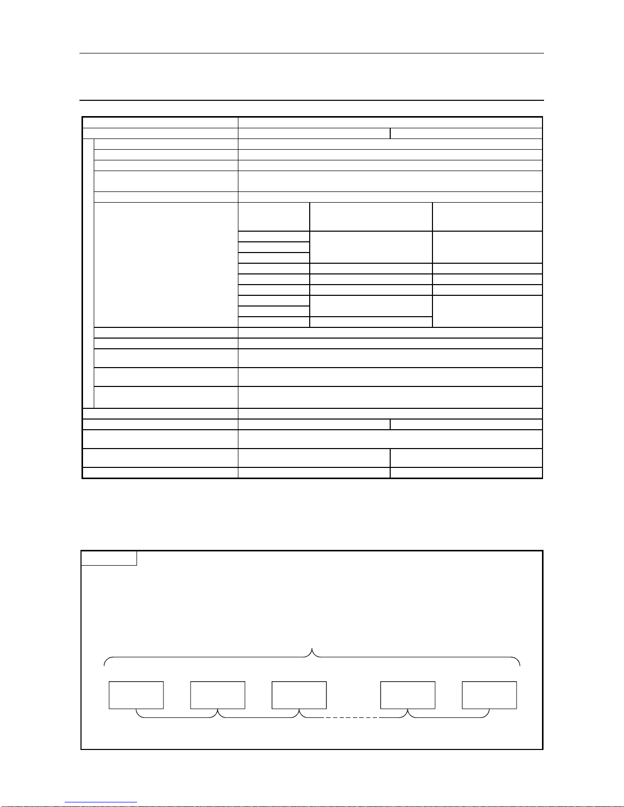
3.3.1 Basic configuration
1) Equipment types
• Class 1 master
• Configurator
• Slave
• Repeater
2) Number of units that can be connected to the entire network (when repeaters are used)
Master+slave ≤ 126 units
3) Number that can be connected for 1 segment
Master+slave+repeaters ≤ 32 units
4) Communications can be conducted via a maximum of 3 repeaters from an arbitrary master or
arbitrary slave to an arbitrary master or arbitrary slave (Not 3 units in the entire network).
5) The maximum number of slaves that can be connected to 1 AJ71PB92D/A1SJ71PB92D is 60
stations.
CPU module
Master (class 1)
AJ71PB92D
A1SJ71PB92D
Configurator
Slave Slave Slave
• The PROFIBUS-DP cable is provided by the user.
Page 21
3. SPECIFICATIONS MELSEC-A
3-4
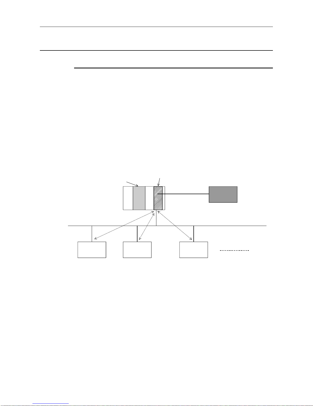
3.3.2 Applicable configuration
1) When 1 master (class 1) station is connected
Master (class 1)
AJ71PB92D
A1SJ71PB92D
CPU mlodule
Configurator
Slave
Slave Slave
Station No. 1 Station No. 2 Station No. 31
*: A maximum of 32 stations can be connected to 1 segment.
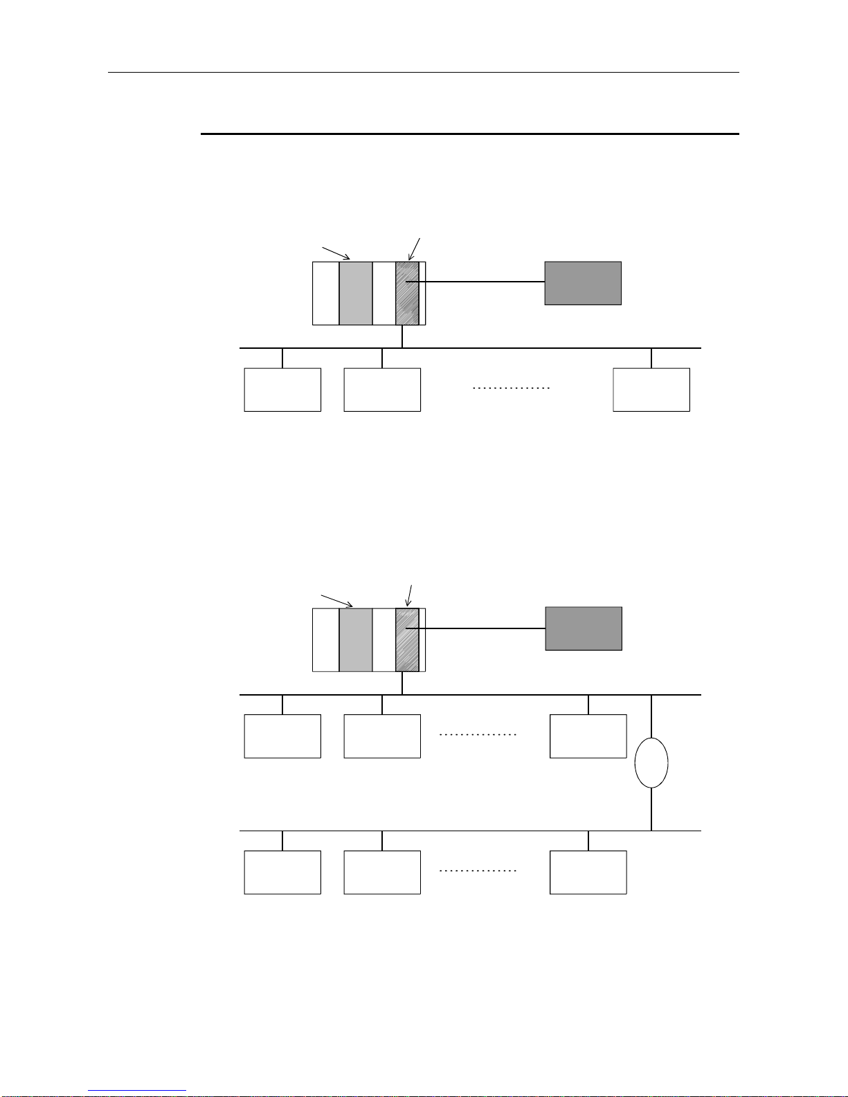
2) When 1 master (class 1) station and 1 repeater are connected
Master (class 1)
AJ71PB92D
A1SJ71PB92D
CPU module
Configurator
Slave
Station No. 1
Slave
Station No. 2
Slave
Station No. 30
Slave
Station No. 31
Slave
Station No. 32
Slave
Station No. 60
Repeater
*: In the above configuration a maximum of 60 slaves can be connected.
Page 22
3. SPECIFICATIONS MELSEC-A
3-5
3) When 1 master (class 1) station and 3 repeaters are connected
Master (class 1)
AJ71PB92D
A1SJ71PB92D
CPU module
Configurator
Slave
Station No. 19
Slave
Station No. 35
Slave
Station No. 36
Slave
Station No. 44
Slave
Station No. 45
Slave
Station No. 60
Slave
Station No. 1
Slave
Station No. 2
Slave
Station No. 18
Repeater
Repeater
Repeater
*: In the above configuration a maximum of 60 slaves can be connected. The difference between
this configuration and the one in 2) is that the possible communication distance can be
extended.
Page 23
3. SPECIFICATIONS MELSEC-A
3-6
4) When 126 master (class 1) and slave stations are connected
(When 60 or more slaves are connected)
CPU module
Slave
Station No. 1
Slave
Station No. 19
Slave
Station No. 56
Slave
Station No. 57
Slave
Station No. 85
Slave
Station No. 86
Slave
Station No. 107
Slave
Station No. 108
Slave
Station No. 123
Slave
Station No. 14
Slave
Station No. 15
Slave
Station No. 18
Repeater
Repeater
Repeater
1st master
(class 1)
2nd master
(class 1)
3rd master
(class 1)
: This slave is controlled by t he 1st master (class 1).
: This slave is controlled by t he 2nd master (class 1).
: This slave is controlled by t he 3rd master (class 1).
Repeater
*: In the above configuration a maximum of 123 slave stations can be connected.
Page 24

3. SPECIFICATIONS MELSEC-A
3-7
Point
In configurations that use multiple master stations (multimaster configuration), when reconnecting
a cable after disconnecting a PROFIBUS cable for 1 master that is exchanging data at a low baud
rate, the communications of the master for which the cable is not disconnected could stop and
the slave output could be turned off. To prevent this, the master PROFIBUS cable must be
secured with a screw.
In addition, there is a high possibility that the above phenomena can be avoided if care is taken
with the following points when configuring a system.
(1) Set the slave watchdog timer setting value to larger than (T
T
r × G)/BR. However,
TTr : Target token rotation time (Unit: Bit Time)
G : Gap update factor
BR : Baud rate (Unit: bps)
(2) Use a high baud rate.
(3) The HSA (Highest Station Address) value is made to match the maximum station No. that is
actually connected.
Page 25

3. SPECIFICATIONS MELSEC-A
3-8
3.3.3 Number of connectable slaves
Please calculate the number of the slave which can be connected under the following
(1) and (2) conditions.
(1) Restrictions on maximum data length of slave station error
information
The maximum data length of the slave station error information that the
AJ71PB92D/A1SJ71PB92D can receive varies with the minimum station number
and maximum station number of the slave stations set in the parameters, and can
be calculated using the following expression.
Maximum data length of acceptable error information [bytes] = Min
12600
N - 10
, 244
N = Min((a - b + 1) 5, 300)
a: Maximum station number of slave station
b: Minimum station number of slave station
: Min(a, b) = A or B, whichever is smaller
If the maximum data length (Max_Diag_Data_Len) of the error information
described in the GSD file of a slave station is greater than the value calculated by
the above expression, normal communication may not be made with that slave
station.
If normal communication cannot be made, try the following methods:
(a) Set the station numbers of the slave stations with no unused numbers in
between.
(b) Make setting on the slave station side to shorten the maximum data length of
the error information. (If possible)
(c) Using two or more AJ71PB92D/A1SJ71PB92D, reduce the number of slave
stations per module.
(2) Restrictions on parameter data length of slav e stati on
The parameter size which can be set in AJ71PB92D/A1SJ71PB92D should meet
the following formula.
Note that the system construction which does not meet the following formula
causes the error of 1302
H
.
5 +
i = 1
n
(number of parameter blocks of each slave station) 128
n = number of slave stations
(number of parameter blocks of each slave station) = sum total of the numbers of parameter
blocks calculated by each slave station
Page 26
3. SPECIFICATIONS MELSEC-A
3-9
The number of parameter blocks for each station is decided by the parameter size
of the station as follows.
Parameter size of each
slave station
Number of blocks of each
slave station
246 bytes or less 1 block
247 to 480 bytes 4 blocks
481 to 720 bytes 5 blocks
721 to 762 bytes 6 blocks
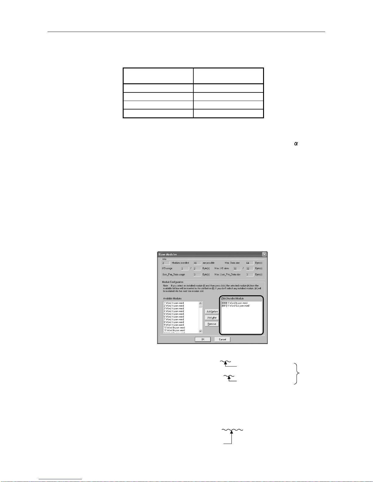
Calculate the parameter size of each slave station using the following formula.
Parameter size of each slave station = 31 + (User_Param data length)
+ (configuration data length) +
(a) User_Param data length
The value of User_Prm_Data usage on the screen displayed when Select
Modules is selected on the slave station setting screen of GX ConfiguratorDP.
(b) Configuration data length
The value differs depending on the slave station type as shown below.
1) Module type slave station
Sum of the number of Module set values, which are described in the
GSD file of the slave station, of the modules registered to the [slot]
Installed Module list.
SD file descriptio n
Module="1 Word In,con word" 0x50
Module="1 Word Out,con word" 0x60
Number of set values is "1"
Number of set values is "1"
Configuration
data length is
"2".
(Example) [slot] Installed Module registration status of GX Configurator-DP
2) Block type slave station
Number of Module set values described in the GSD file of the slave
station.
(Example) GSD file description
Module="1 Byte Out,3 Byte In" 0x20,0x12
As the number of set values
is "2", the configuration data
len
g
th is "2".
Page 27

3. SPECIFICATIONS MELSEC-A
3-10
(c)
(constant)
= 2 : When the slave station has only input or output
= 4 : When the slave station has both input and output
(example)
When the system is constructed using only the stave stations with 520 bytes
parameter, AJ71PB92D/A1SJ71PB92D can be connected up to the following
number of the slave stations.
When the parameter size is 520 bytes, the number of the parameter block is five.
5 + (5
n) 128 : n = number of slaves
n = 24.6
128 - 5
5
n = 24
The calculation mentioned above tells that AJ71PB92D/A1SJ71PB92D can be
connected up to 24 slave stations.
Therefore, when 25 slave stations or more are set by the parameter,
AJ71PB92D/A1SJ71PB92D detects the error of 1302
H
.
Page 28
4. FUNCTIONS MELSEC-A
4-1
4. FUNCTIONS
4.1 Functions for Exchanging with Slaves
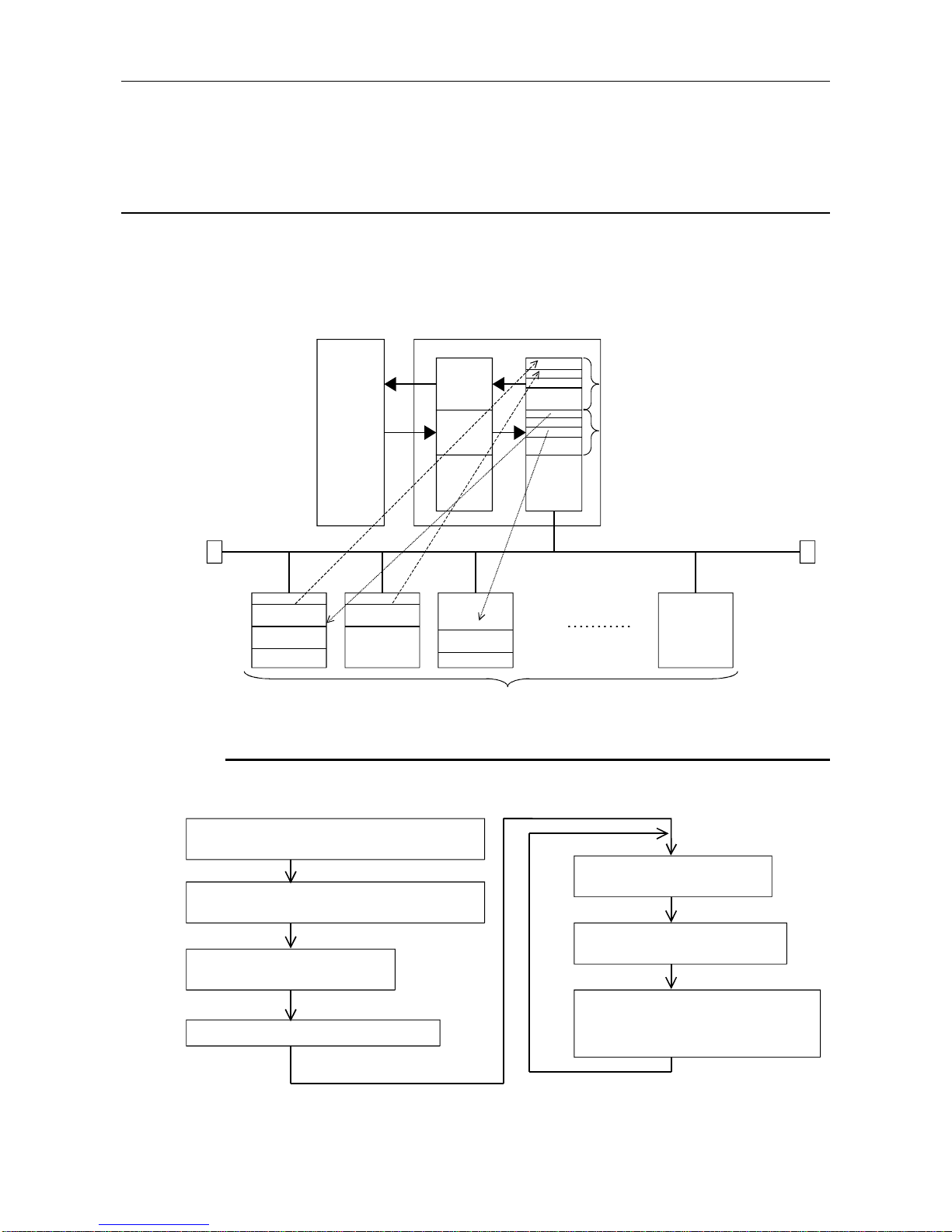
The main function in the AJ71PB92D/A1SJ71BP92D is for exchanging I/O data with slave stations
connected to the PROFIBUS-DP network. The method used for this exchange is to read/write the I/O
image in the buffer memory using FROM/TO instructions.
A schematic drawing of this exchange function is as follows.
CPU module
AJ71PB92D/
A1SJ71PB92D
(Class 1 master)
FROM
TO
Buffer memory
Input
image
Output
image
Input
image
Output
image
Input image Input image
Output image
Output image
PROFIBUS-DP network
Slave stati on
4.1.1 Exchange flow
The I/O data exchange flow with slave station is shown below.
* The buffer memory refresh with the FROM/TO instructions is conducted asynchronously.
Set the slave troubl e in fo rm ation cancel area.
(Setting is unnecessary if the default value can be left
unchanged.)
Communication trouble area type selection
(This setting is unnecessary if the default value can
be left unchange d.)
Write the initial OUTPUT dat a value in
the output area.
Turn ON the exchange start request signal (Y00).
Check that the exchange start/end
signal (X00) is ON.
Read the input dat a from the input area
using the FROM instruction.
Write the OUTPUT data in the output area in the
buffer memory using the TO instruction.
Page 29
4. FUNCTIONS MELSEC-A
4-2
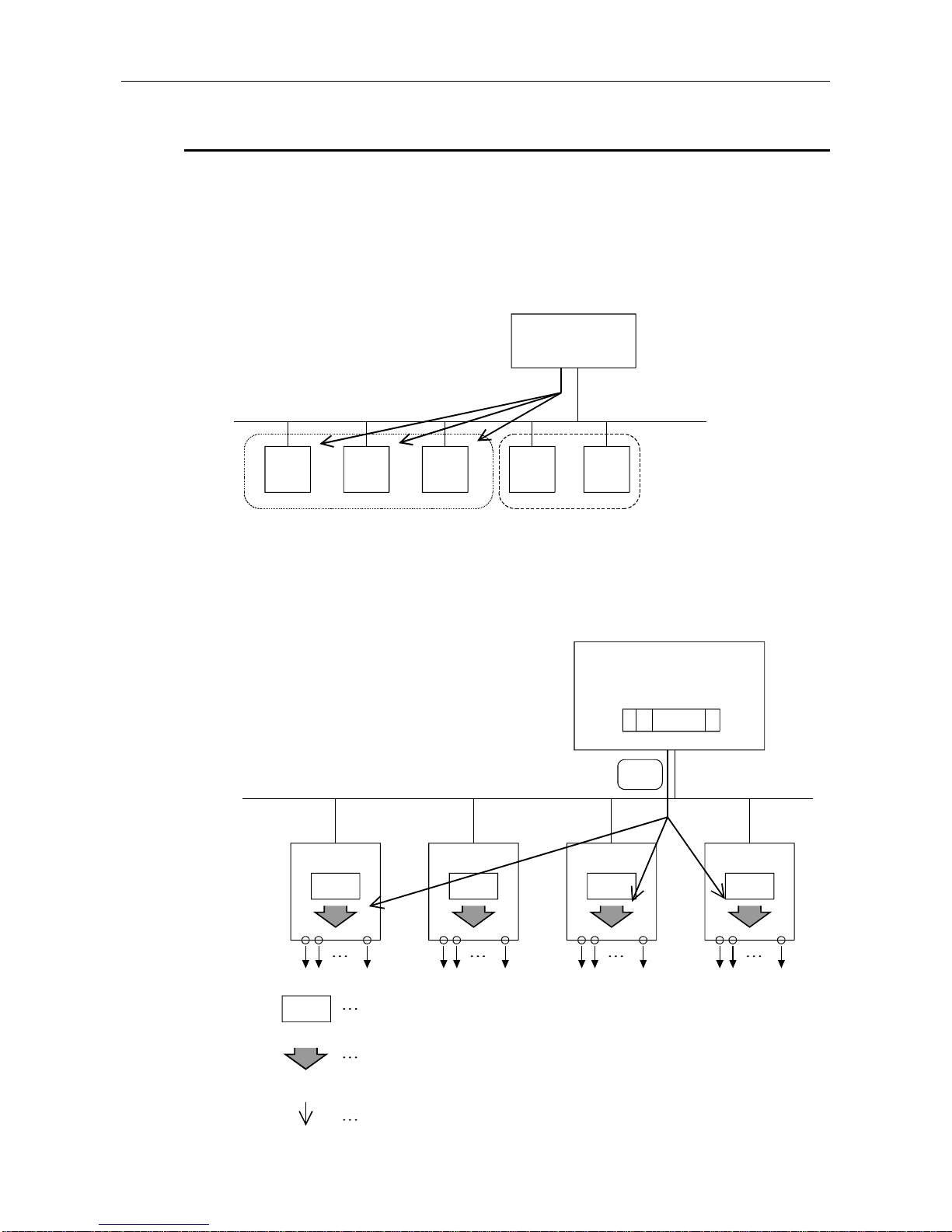
4.1.2 Global control functions
Global control contains the four functions of SYNC, UNSYNC, FREEZE, and UNFREEZE, which are
functions that are used to maintain/cancel slave I/O for which multicast communication is conducted at
the same time.
The slaves that execute the global control function are those located in one or more groups of the
eight groups. The group No. of the group containing the slaves is set by the configurator. In the
AJ71PB92D/A1SJ71PB92D the group can be arbitrary specified and the global control commands
transmitted using multicast communication. This makes is possible to select a slave and conduct
global control.
Master
PROFIBUS-DP network
Group 1
Group 5
The global control function is executed using X, Y, and FROM/TO instructions from the sequence
program.
(1) Service SYNC, UNSYNC
Master
(SYNC transmission to group 1)
Output data
SYNC
(Group 1) (Group 2)
(Group 1)
(Group 1)
Slave 1 Slave 2 Slave 3 Slave n
Output image memory: Data is always refreshed using polling.
<During UNSYNC execution/default>The output image memory value is output unchanged
(normal condition)
<During SYNC execut ion>The output image memory value is only output once during the
SYNC service timing.
Service SYNC (issued in the same group)
Page 30
4. FUNCTIONS MELSEC-A
4-3
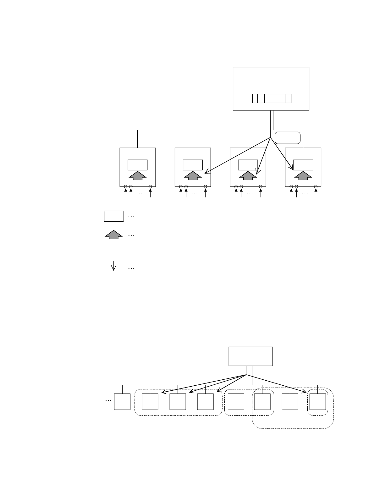
(2) Service FREEZE, UNFREEZE
(Group 8)
Slave 1
(Group 3)
Slave 2
(Group 3)
Slave 3
(Group 3)
Slave n
Master
(FREEZE transmission to group 3)
Input data
FREEZE
Input image memory: The data is always refreshed by polling.
<during FREEZE cancel/default>The actual input is input to the input memory unchanged
(normal condition)
<during FREEZE execute>The actual input is input once into the input image memory at the FREEZE
service timing.
Service FREEZE (issued within the same group)
(3) Group selection
• The number of groups is from 1 to 8 if with a total of 8 groups.
• The slave can exist in arbitrary group of the 8 groups. They can also exist in multiple groups.
(The configurator specifies in which group which slaves exist.)
• Multiple groups can be arbitrarily selected from the sequence program and global control
executed.
• When selecting group 0 and transmitting the service is transmitted to all slave stations.
Master
(transmitted to
groups 1 and 2)
PROFIBU S-DP network
Slave
Group 1
Group 5
Group 2
Group 8
Page 31

4. FUNCTIONS MELSEC-A
4-4
(4) Procedure for issuing a global service.
Sequence
program
A1SJ71PB92D Slave
TO global control area
Turn on the global co ntr o l
request signal (Y04).
Turn on the global co ntr o l
end signal (X04).
Time
Global control service
AJ71PB92D
Page 32

4. FUNCTIONS MELSEC-A
4-5
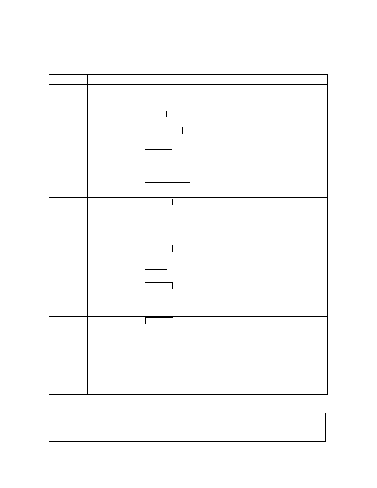
4.2 I/O Signal
4.2.1 I/O signal list
The I/O signal configuration used in the AJ71PB92D/A1SJ71PB92D and the data communications
with the PLC CPU are described below.
Signal direction: AJ71PB92D/A1SJ71PB92D
→→→→
PLC CPU Signal direct ion: PLC CPU
→→→→
AJ71PB92D/A1SJ71PB92D
Device No. Description Device No. Description
X00 Exchange start end signal Y00 Exchange start request signal
X01 Communication trouble detection signal Y01 Communication trouble det ec t ion s ignal res et
X02 Communication trouble area clear end signal Y02 Communication trouble area clear request signal
X03 Not usable Y03 Communication trouble area t ype selec tion
X04 Global control end signal Y04 Global control request signal
X05 Global control error end
X06
…
……
…
X0C
Not usable
Y05
……
…………
……
Y0C
Not usable
X0D W at c hdog t im er error s ignal Y0D St art up reques t s ignal
X0E
X0F
Not usable
X10 Operation mode signal
Y0E
…
……
…
Y10
Not usable
X11 Operation mode change completion signal Y11 Operation mode change request signal
X12
…
……
…
X1A
Not usable
X1B Communication READY signal
X1C Not usable
X1D Module READY signal
X1E to X1F
Not usable
Y12
…
……
……
……
……
……
……
……
……
……
……
……
…
Y1F
Not usable
Point
If a device which is not usable is accidentally turned on and off in the sequence program, it
cannot guarantee as the AJ71PB92D/A1SJ71PB92D function.
Page 33

4. FUNCTIONS MELSEC-A
4-6
4.2.2 I/O signal detail description
(1) Exchange start request signal (Y00), exchange start end signal (X00)
(a) After the exchange start request signal (Y00) is turned on by the sequence program the
exchange start end signal (X00) is turned on when cyclic exchange starts.
(b) The exchange start end signal (X00) turns off in either of the following cases.
• When the exchange start request signal (Y00) is turned off
• When the parameters are written from the configurator to the AJ71PB92D/A1SJ71PB92D
Exchange start request sign al (Y00)
Exchange start end signal (X00)
Exchange start
request
Exchange start end
Maximum 200 ms
Exchange
(c) An interlock is used for FROM/TO of the I/O data.
(d) Before the exchange start request signal is turned on the output data initial value must be
written to the buffer memory.
(2) Communication trouble detection signal (X01), communication trouble detection signal
reset (Y01)
(a) The communication trouble detection signal (X01) is turned on when a communication
trouble occurs. At the same time the RSP ERR.'s LED turns on. At this time the error code
and detailed data are stored in the buffer memory communication trouble area.
(b) The communication trouble detection signal (X01) is turned off when the communication
trouble detection signal reset signal (Y01) is turned on from the sequence program or when
communication failure is all resolved. At this time, the RSP ERR. LED is turned off.
(c) The communication trouble detection signal reset (Y01) is turned off by the sequence
program after it has been confirmed that the communication trouble detection signal (X01)
has been turned off.
(d) The following sequence is used.
Communication trouble detection signal reset (Y01)
Communication trouble detection signal (X01)
Trouble detection
Trouble detection reset
FROM
The error code is read from the buffer memory to the PLC CPU.
FROM/TO
Page 34

4. FUNCTIONS MELSEC-A
4-7
(3) Communication trouble area clear request (Y02), communication trouble area clear end
(X02)
(a) The communication trouble area clear request (Y02) is turned on by the sequence program
when all of the communication trouble areas and extension trouble areas are cleared.
(b) The communication trouble clear end signal (X02) is turned on after all of the communication
trouble area and extension trouble areas are cleared by turning on the communication
trouble area clear request signal (Y02).
(c) The communication trouble area clear request (Y02) is turned off by the sequence program
after it has been confirmed that the communication trouble area clear end signal (X02) has
been turned on.
(e) When the communication trouble area clear request signal (Y02) is turned off the
communication trouble area clear end signal is turned off.
(d) A sequence like the one below is used.
Communication trouble area clear request (Y02)
Communication troublev area clear end (X02)
Clear request
Clear end
(4) Global control request signal (Y04), global control end signal (X04)
(a) The global control end signal (X04) is turned on after service processing has ended when
the global control request signal (Y04) is turned on by the sequence program.
(b) The global control request signal (Y04) is turned off by the sequence program after it has
been confirmed that the global control service end signal (X04) has turned on.
(c) When the global control request signal (Y04) is turned off the global control end signal (X04)
turns off.
(d) The global control request signal (Y04) cannot be received if the exchange starting (X00) is
not on. If Y04 is turned on when X00 is off then both X04 and X05 will turn on.
(e) A sequence like the one below is used.
Global control request
X00
Global control end
TO
Output data write
Exchange start end signal (X00)
Global control request signal (Y04)
Global control end signal (X04)
(5) Global control error end signal (X05)
(a) If global control is requested when exchange start (X00) is not on then global control error
end (X05) and the global control service end signal (X04) will turn on at the same time.
(b) The slave I/O is not held/deleted when the global control error end signal (X05) is on.
Global control request
Global control end
Global control error end
Global control request signal (Y04)
Global control end signal (X04)
Global control error end signal (X05)
Page 35

4. FUNCTIONS MELSEC-A
4-8
(6) Watchdog timer error end (X0D)
(a) This turns on when a Watchdog timer error occurs.
(b) This will not turn off until the module is reset or its power supply is turned off and on.
(7) Operation mode signal (X10)
Indicates whether the current operation mode is the parameter setting mode or not.
ON: Parameter setting mode
OFF: Normal service mode/extended service mode
(8) Operation mode change request signal (Y11), operation mode change completion signal
(X11)
Used to change the operation mode without resetting the CPU module.
This function is valid only when a start is made with the mode setting switch in the 0, 1 or E
position.
(a) Operation mode change request signal (Y11)
OFF¨ON: Requests the operation mode to be switched to the one specified in the
operation mode change request area (address 2255/8CFh) of the buffer memory.
ON¨OFF: Turns off X11.
(b) Operation mode change completion signal (X11)
Turns on when the result is stored into the operation mode change result area (address
2256/8D0h) of the buffer memory. This signal also turns on on normal or abnormal
completion of an operation mode change.
This signal turns off when Y11 turns from ON to OFF.
(9) Communication READY signal (X1B)
(a) This is turned on when the station enters the exchange start possible state after the
AJ71PB92D/A1SJ71PB92D has started up and the module READY signal (X1D) has turned
on. (Only during the normal transmission mode.)
(b) This turns off when a exchange continuation impossible error occurs.
(c) The exchange start request signal (Y00) is used as an interlock when turned on by the
sequence program.
(10) Module READY signal (X1D)
(a) This is turned on when the AJ71PB92D/A1SJ71PB92D is started up.
Therefore, it is turned on regardless of the operation mode.
(b) This is turned of when the AJ71PB92D/A1SJ71PB92D goes down.
(11) Communication trouble area type selection (Y03)
(a) This is used to select the communication trouble area type (ring type or fixed type).
(b) This is turned off when ring type is selected and on when fixed type is selected.
(c) This signal becomes valid when the exchange start or communication trouble area clear
request (Y02) is on.
Communication trouble area
type selection (Y03)
Fixed type
selection
Ring type selection
Initial type
(Becomes valid)
Exchange start or communication
trouble area clear request (Y02) on
(12) Restart request signal (Y0D)
(a) When the AJ71PB92D/A1SJ71PB92D goes down for some reason (when the FAULT LED
turns on and X1D is off) then turning Y0D from off to on to off again will make it possible to
restart the AJ71PB92D/A1SJ71PB92D.
(b) The same state will be entered if after start up the power supply is turned off and then on
again.
Page 36

4. FUNCTIONS MELSEC-A
4-9
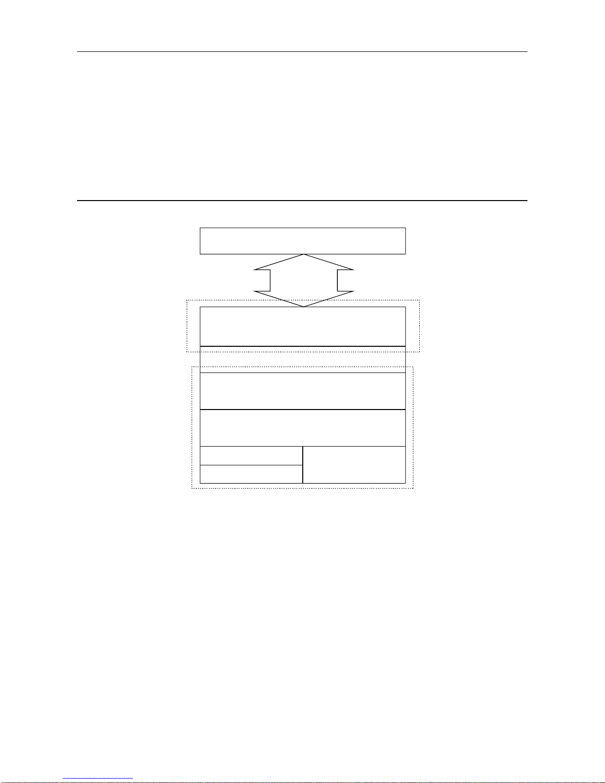
4.3 Buffer Memory List
4.3.1 Buffer memory/configuration
The configuration of the buffer memory used to receive and send data with the AJ71PB92D/
A1SJ71PB92D and the PLC CPU is described below.
Buffer memory address
(decimal/hexadecimal)
0/
959/
0h
3BFh
Input area
(Description)
This is the area that stores the input data from the slave.
960/
1919/
3C0h
77Fh
Output area
(Description)
This is the area that stores the output data to the slave.
1920/
2039/
780h
7F7h
Address information area
(Description)
This is the area that shows the slave address and I/O data length.
2040/
2079/
7F8h
81Fh
Communication trouble area
(Description)
This is the area that shows the trouble information that occurred during communication.
2080/ 820h Slave error information cancel area
(Description)
This is the area that sets the data that masks the slave trouble information.
2081/ 821h Global control area
(Description)
This is the global control function hold/cancel selection area.
2082/ 822h Not usable
2083/ 823h Time out time setting area (Closed to users because this is a debugging function.)
(Description)
This is used to set the time out time when an exchange start/stop is executed.
2084/ 824h Trouble no information time setting area
(Description)
This is used to set the time that does not inform the communication trouble after the exchange start.
2085/
2095/
825h
82Fh
Not usable
2096/
2110/
830h
83Eh
Expansion communication trouble area
(Description)
This area shows the expansion information of the trouble information which is occurred during the
communication.
2111/ 83Fh Not usable
2112/ 840h Slave status area
(Description)
2116/ 844h This is the area that shows the status information of each slave.
2117/
2127/
845h
84Fh
Not usable
2128/
2247/
850h
8C7h
Input/Output start address area (Extended service mode only)
(Description)
This is the area that shows the addresses to start the input area and output area of each slave.
2248/
2253/
8C8h
8CDh
Not usable
2254/ 8CEh Current operation mode
(Description)
This area indicates the operation mode of the AJ71PB92D/A1SJ71PB92D when it has started up.
2255/ 8CFh Operation mode change request area
(Description)
In this area, set the operation mode of the AJ71PB92D/A1SJ71PB92D which you want to choose.
2256/ 8D0h Operation mode change result area
(Description)
This area indicates the execution result of the operation mode change request.
2257/
3775/
8D1h
EBFh
Not usable
Point
Don't read and write to the buffer memory which is not usable.
If you perform it, it cannot guarantee as the AJ71PB92D/A1SJ71PB92D function.
Page 37

4. FUNCTIONS MELSEC-A
4-10
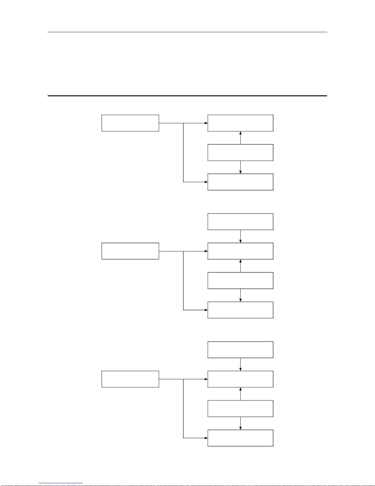
4.3.2 Buffer memory detailed description
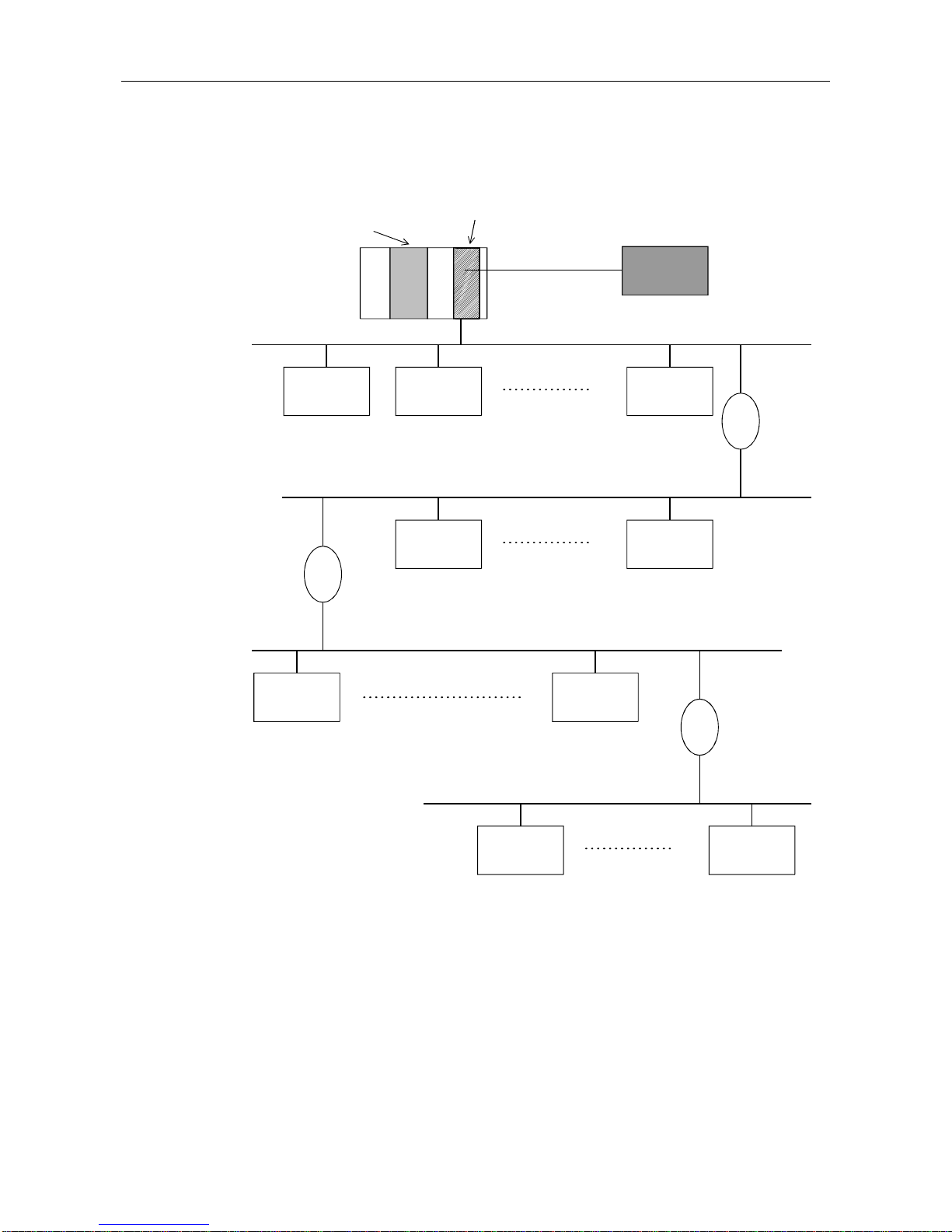
(1) INPUT area
Either normal service mode or extended service mode can be selected via the mode switch on
the main unit.
(a) Normal service mode (MODE switch : No. 0)
This is the area that stores the input data from the slave station.
This area is fixed to an allocation of 32 bytes (16 words) per station for a total of 60 stations
worth. This input area configuration is as follows.
Example : When the input data length for the first station is set to 29 bytes and that for the
second station to 32 bytes
Address
Address
1st station input data
2nd station input data
n th station input data
60th station input data
1st station 2nd byte
1st station 4th byte
1st station 1st byte
1st station 3rd byte
1st station 29th byte
b15
b0
2nd station 2nd byte
2nd station 4th byte
2nd station 1st byte
2nd station 3rd byte
2nd station 30th byte
2nd station 32nd byte
2nd station 29th byte
2nd station 31st byte
b15
b0
(Upper byte)
(Lower byte)
: Free area (00h)
*1: Since the data area is fixed to 32 bytes,
all unused areas will become free.
*1
*1
0/0h
15/Fh
16/10h
31/1Fh
944/3B0h
959/3BFh
0/0h
1/1h
14/Eh
15/Fh
16/10h
17/11h
30/1Eh
31/Fh
Point
The input data of the slave station, which was disabled from communication during normal
communication and whose corresponding bit of the communication status area*1 turned ON (1),
is not stored into the input area of the AJ71PB92D/A1SJ71PB92D.
In the input area of the corresponding slave station, the data before communication failure is
held.
*1: Indicates the area of buffer memory addresses 2113 (841
H
) to 2116 (844H) in the slave status
area.
Page 38

4. FUNCTIONS MELSEC-A
4-11
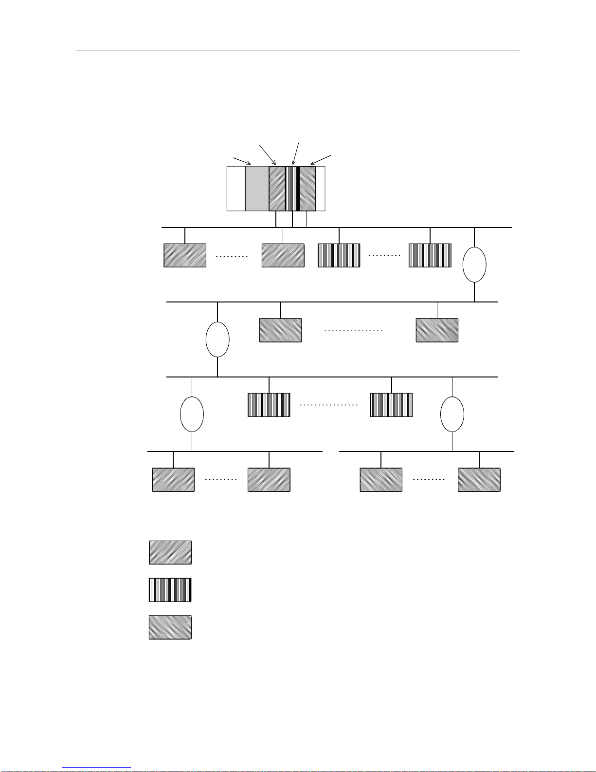
(b) Extended service mode (MODE switch : No. E)
This is the area that stores the input data from the slave station.
In this area, the data length (in byte units) for each station is assigned in variable length
according to the parameter file set in the configurator software package.
The data length can be set in the range of 0 to 244 bytes.
Number of stations that can be set will vary in the range of 1 to 60, depending on the
specified data length. For example, seven stations can be set if the data length for each
station is 244 bytes, and 60 stations if the data length is 32 bytes.
Example : When the input data length for the first station is set to 23 bytes and that for the
second station to 7 bytes
Address
Address
0/0h
11/Bh
12/Ch
1st station input data
2nd station input data
n th station input data
60th station input data
1st station 2nd byte
1st station 4th byte
1st station 1st byte
1st station 3rd byte
1st station 22nd byte
1st station 21st byte
1st station 23rd byte
0/0h
10/Ah
11/Bh
2nd station 2nd byte
2nd station 4th byte
2nd station 1st byte
2nd station 3rd byte
12/Ch
13/Dh
2nd station 6th byte
2nd station 5th byte
2nd station 7th byte
14/Eh
15/Fh
1/1h
15/Fh
b15
b0
*2
b15
b0
(Upper byte)
(Lower byte)
: Free area (00h)
*2: When the data lenghth is set to an odd number
of bytes, the last upper byte becomes a free area
and data for the next station is assugned from
the next address.
Point
The input data of the slave station, which was disabled from communication during normal
communication and whose corresponding bit of the communication status area*1 turned ON (1),
is not stored into the input area of the AJ71PB92D/A1SJ71PB92D.
In the input area of the corresponding slave station, the data before communication failure is
held.
*1: Indicates the area of buffer memory addresses 2113 (841
H
) to 2116 (844H) in the slave status
area.
Page 39

4. FUNCTIONS MELSEC-A
4-12
(2) OUTPUT area
Either normal service mode or extended service mode can be selected via the mode switch on
the main unit.
(a) Normal service mode (MODE Switch : No. 0)
This is the area that stores the output data to the slave station.
This area is fixed to an allocation of 32 bytes (16 words) per station for a total of 60 stations
worth. This output area configuration is as follows.
Example : When the output data length for the first station is set to 1 bytes and that for the
second station to 3 bytes
Address
Address
960/3C0h
975/3CFh
976/3D0h
991/3DFh
1904/770h
1919/77Fh
1st station output data
2nd station output data
n th station output data
60th station output data
1st station 1st byte
b15
b0
960/3C0h
961/3C1h
974/3CEh
975/3CFh
2nd station 2nd byte 2nd station 1st byte
2nd station 3rd byte
976/3D0h
977/3D1h
991/3DFh
b15
b0
(Upper byte)
(Lower byte)
: Free area (00h)
*1: Since the data area is fixed to 32 bytes,
all unused areas will become free.
*1
*1
(b) Extended service mode (MODE switch : No. E)
This is the area that stores the output data to the slave station.
In this area, the data length (in byte units) for each station is assigned in variable length
according to the parameter file set in the configurator software package.
The data length can be set in the range of 0 to 244 bytes.
Number of stations that can be set will vary in the range of 1 to 60, depending on the
specified data length. For example, seven stations can be set if the data length for each
station is 244 bytes, and 60 stations if the data length is 32 bytes.
Example : When the output data length for the first station is set to 19 bytes and that for the
second station to 5 bytes
Address
Address
1st station output data
2nd station output data
n th station output data
60th station output data
1st station 2nd byte
1st station 4th byte
1st station 1st byte
1st station 3rd byte
1st station 18th byte
1st station 17th byte
1st station 19th byte
2nd station 2nd byte
2nd station 4th byte
2nd station 1st byte
2nd station 3rd byte
2nd station 5th byte
b15
b0
*2
b15
b0
: Free area (00h)
*2: When the data lenghth is set to an odd number
of bytes, the last upper byte becomes a free area
and data for the next station is assugned from
the next address.
(Upper byte)
(Lower byte)
960/3C0h
968/3C8h
969/3C9h
970/3CAh
971/3CBh
972/3CCh
961/3C1h
960/3C0h
969/3C9h
970/3CAh
972/3CCh
Page 40

4. FUNCTIONS MELSEC-A
4-13
(3) Address information area
This area shows the station address, input byte length, and output byte length for each slave
station. This allocation is set by the configurator. The station addresses for the 1st through the
60th stations are stored in the order of registration in the configurator. (Station addresses: 1 to
126, do not need to be sequential numbers.)
The address information area configuration is shown below. For details refer to Section 4.3.2 (4).
Address
1920/780h
1921/781h
1922/782h
1923/783h
2036/7F4h
2037/7F5h
2038/7F6h
2039/7F7h
Station address of 1st station
1st station input byte length 1st station output byte length
Station address of n station
n th station input byte length n th station output byte length
Station address of 59th station
59th station input byte length 59th station output byte length
Station address of 60th station
60th station input byte length 60th station output byte length
2nd station input byte length
2nd station output byte length
Station address of 2nd station
(a) The station address of unallocated stations is FFFFh, and the I/O byte is FFh.
(b) When the I/O byte length of allocated stations is 0, a 0 is stored for the byte length.
(c) The n does not show the station address but represents a number (the nth number) used for
the input/output area.
Page 41

4. FUNCTIONS MELSEC-A
4-14
(4) Example address information area, INPUT area, and OUTPUT area
The AJ71PB92D/A1SJ71PB92D reads the slave station address and I/O byte length set by the
parameter file which is set by the configurator and stores these in the buffer memory address
information area.
With the AJ71PB92D/A1SJ71PB92D, I/O areas are assigned to each slave station based on the
I/O byte length information in the address information area, and each I/O data will be stored in the
corresponding buffer memory area.
Example : At extended service mode
Address
Address information area
1920
1921
1922
1923
5
: Vacant area
CPU module
AJ71PB92D
A1SJ71PB92D
Slave
Slave
PROFIBUS-DP
network
Station address : 10
Input data length : 7 byte
Output data length : 5 byte
963/3C3h
Address
1st station 2nd input byte
INPUT/OUTPUT area
0/0h
1/1h
2/2h
959/3BFh
9600/3C0h
961/3C1h
1919/77Fh
IN P UT
OUTPUT
1st station1st input byte
3/3h
4/4h
5/5h
6/6h
1st station 3rd input byte
2nd station 2nd input byte
2nd station 1st input byte
2nd station 4th inp ut byte
2nd station 6th inp u t byte
2nd station 3rd input byte
2nd station 5th input byte
2nd station 7th input byte
2nd station 2nd output byte 2nd station 1st output byte
2nd station 4th output byte 2nd station 3rd output byte
2nd station 5th output byte
b15
b0
b15
b0
*
1
0
*
3
3
*
2
10
57
962/3C2h
*4
Station address : 5
Input data length : 3 byte
Output data length : 0 byte
*1: Station address (FFFFh if not assigned)
*2: Input byte length (FFh if not assigned)
*3: Output byte length (FFh if not assigned)
*1, *2 and *3 are also set in a reserved station.
(The free areas in the INPUT area
are initialized with [00h].)
*4: Since output from the first station has a byte length of 0,
no area is allocated in the OUTPUT area.
Page 42

4. FUNCTIONS MELSEC-A
4-15
(5) Communication trouble area
When some kind of trouble occurs during communication the AJ71PB92D/A1SJ71PB92D stores
the contents of the trouble in this area. Fixed type or ring type can be selected for this area by
turning the communication trouble area type selection (Y03) on or off (refer to Section 4.2.2 (9)).
As shown in the following diagram, a total of 8 pieces of trouble information that consist of the
trouble code, detailed data length, and detailed data can be stored in the basic configuration
regardless of whether for fixed or ring data.
Ring type data is stored in order from the header with the header always being the latest trouble
information.
With fixed type data, when 8 pieces of trouble information are stored the areas 2 to 8 (data 1 to 7)
are fixed, so when the next new trouble occurs only header area 1 (data 8) is updated.
All trouble information for either type can be cleared by turning on the communication trouble
area clear request signal (Y02). When the communication trouble detection signal reset signal
(Y01) is on, the contents of the communication trouble area are held though the communication
trouble detection signal (X01) turns off.
The communication trouble area is configured as shown below.
(a) Communication trouble area configuration
Address
2040/7F8h
2044/7FCh
2045/7FDh
2049/801h
2050/802h
2054/806h
2075/81Bh
2079/81Fh
Trouble information area 1
Trouble information area 2
Trouble information area 3
Trouble information area 8
2040/7F8h
2041/7F9h
2042/7FAh
2043/7FBh
2044/7FCh
Error code (refer to the next page.)
Detailed data length (0 to 3)
Detailed data 1
Detailed data 2
Detailed data 3
Data 1
Ring type
Fixed type
Trouble
information area 1
Trouble
information area 2
Trouble
information area 1
Trouble
information area 2
Trouble
information area 8
Trouble
information area 8
Data 2 Data 9Data 8
Data 1
Data 2
Data 1
Data 1
Data 7
Data 1
Data 8
Data 7
Data 1
Data 8
Data 2
Data 9
Data 7
Data 1
Address
Page 43

4. FUNCTIONS MELSEC-A
4-16
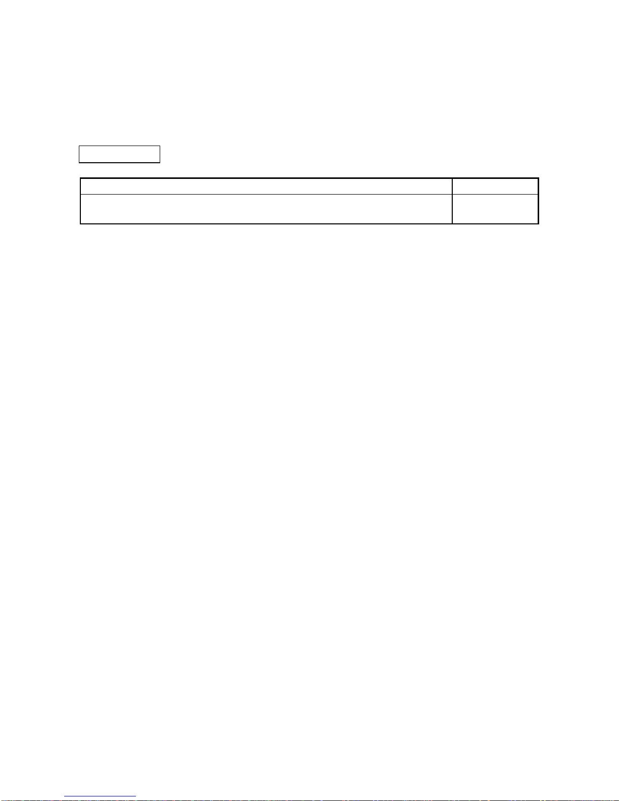
(b) Error codes
The error codes are shown below.
Error Data Detailed data CommuniCode length
123
cation state
0200h (c)
Ref.
(c)
Ref.
(c)
Ref.
(c)
Ref.
(c) Ref. (c) Ref.
1121h 1 03h
The slave address specified in the parameter is t he
same as that of the master. This error occurs
immediately after the power supply is turned on or
the CPU is reset. Even though this error is
occurring, if the exchange start (Y00) is on then
error of error code 3000h will occur, the FAULT
LED will turn on, and operation will stop.
×
1300h 2 Contents
ref.
Contents
ref.
Not even 1 active slave station is set in the
parameter. When this error occ urs t he det ailed
data is set to:
Detailed data 1: Number of slaves set in t he
parameter.
Detailed data 2: Number of active slav es s et in
the parameter.
This error occurs immediately after the power
supply is turned on or the CPU is reset. Even
though this error is occurring, if the exchange start
(Y00) is on then error of error code 3000h will
occur, the FAULT LED will turn on, and operation
will stop.
×
1) Set 1 or more active
slaves in the
parameter.
2) When the FAULT
LED is turned on,
reset is enabled by
turning OFF
→ON→
OFF the Y0D
3000h 1 Ignored
1) When the above errors 1300h or 1121h have
occurred before this error:
Refer to errors 1300h, 1121h above.
2) Otherwise
An unexpected error has occurred.
×
For 1)
Refer to the above
1300h, 1121h
errors.
For 2)
Contact the nearest
Mitsubishi Electric
branch office or
dealer.
×: Exchange stops after the error occurs. : Exchange continues.
User processingDescription
Page 44

4. FUNCTIONS MELSEC-A
4-17
(c) When the trouble code = 0200h
For a slave trouble information occurrence (error code = 0200h), the slave trouble
information is stored in the detailed data. The communication trouble area configuration for
this case is shown below. In addition, the expansion communication trouble information is
stored in buffer memory 2096 to 2110 for only the latest trouble information of the error code
= 0200h trouble information. For information regarding the expansion communication trouble
information refer to Section 4.3.2 (6).
Error code = slave trouble information occurrenc e
Detailed data length = 3
Detailed data 1 Master address (*1) Slave address (* 2)
Detailed data 2 Trouble information
Detailed data 3 Slave ID (*3)
*1 The station address of the master station that controls the slave station in which this trouble
information occurred is stored. However, FFh is stored when the trouble information shows
the exchange with the slave is failed.
*2 The station address of the slave station in which this trouble information occurred is stored.
*3 Individual slave inherent ID No. from the PNO is stored. However, FFh is stored for trouble
information that shows that the exchange with the slave failed.
The trouble information is shown in a 16-bit bit string, and the bits that correspond to the
respective trouble occurrences are set. A description of the error information is given below.
bit Description
Communi-
cation state
Processing
Setting
station
15 Controlled by another master. Multiple m as t ers are t rying to c om m unic at e with the same
slave, so recheck the paramet er.
Master
14 The parameter transmitted by the master is
incorrect.
Check the parameter. Slave
13 The response from the slave is incorrect. Check the slave or network status. Master
12 The function requested by the master is not
supported.
Check the slave specifications . Es pec ially if global c ont rol is
supported.
Slave
11 Expansion trouble information exists. Check the slave status. (refer to User's Manual.) Master
10 The I/O byte size parameter received from the
master does not match that of t he slave.
Check the slave parameter. Slave
9 The slave is not ready to exchange. This trouble information will always occur at exchange start,
so it can be ignored. If this trouble occurs during exchange,
check the slave status and c ommunication circuit.
Slave
8 Exchange with the slave cannot be conduct ed. Check the slave status and communication circuit . And c hec k
the parameter.
Master
7 Separated from the cyclic exchange by t he
parameter setting.
This trouble information will always occur at exchange start,
so it can be ignored. Check if the parameter on the network
was changed by a class 2 master.
Master
6 0 (reserved)
Slave
5 The slave has entered the SYNC mode. (Normal operation) Slave
4 The slave has entered the FREEZE mode. (Normal operation) Slave
3 Watc hdog m onit oring is being c onduc t ed in t he
slave.
(Normal operation) Slave
2 0 (fixed)
Slave
1 Diagnostic data read request. Check the slave statue. Slave
0 Parameter allocation request f rom a s lave. This error information will always occur at exchange start, so it
can be ignored. If this error occurs during exchange, chec k
the slave status and comm unic at ion c ircuit.
Slave
: Exchange continues even if trouble occurs.
Page 45

4. FUNCTIONS MELSEC-A
4-18
(6) Expansion communication trouble area
This area shows the latest expansion trouble information for only one of the latest expansion
trouble information in the error code 0200h error information stored in buffer memory K2040 to
K2079 communication error area (Refer to Section 4.3.2 (5)).
Communication trouble area
(
When fixed buffer is selected.
)
Area 1
Area 2
Area 8
No error code=0200h
expansion trouble
information (trouble
information bit 11 = 0)
(Latest data)
There is error code=
0200h expansion
trouble information
(trouble information
bit 11 = 1)
Data 10
Data 7
Data 6
Data 5
Data 4
Data 3
Data 2
Data 1
Address
(decimal/hexadecimal)
2096 /830h
2097 /831h
2110 /83Eh
Expansion trouble information area
(a) Buffer Memory K2096
The latest expansion communication trouble information length stored from buffer memory
K2098 is stored as a byte length unit.
Address
(decimal/hexadecimal)
Expansion trouble information area
9096 /830h
9097 /831h
9098 /832h
2110 /83Eh
21
21 bytes = 10 words + 1 byte
Page 46

4. FUNCTIONS MELSEC-A
4-19
(b) Buffer memory K2097
Only bit 7 is valid. Other bit is fixed in 0. Bit 7 is turned on when the slave sends expansion
trouble information that is 27 bytes or more.
Bit position
MSB
1514131211109876543210
LSB
0 fixed 0 fixed
(c) Buffer memory K2098 to K2110
The following informations are stored in this area:
• Device related trouble information
• This area stores the slave station inherent self-diagnostic information that is not set by
the PROFIBUS-DP standards.
• Identifier related trouble information
• For module type slave stations, whether or not a module error has occurred is stored as
bit information.
• Channel related trouble information
• For module type slave station, this stores the, error information of all modules outputting
an error.
1) Device Related trouble information
This stores the slave module inherent trouble information that is not set by the
PROFIBUS-DP standards. The device related trouble can be divided by header and
trouble information. This area stores a 2 bit value that is the device related trouble
information in the header, including the header (1 byte), and the device related trouble
information for this area.
Buffer memory
2098 /832h
2099 /833h
(2nd byte)
(4th byte) (3rd byte)
Header
(1st byte)
Bit position
MSB LSB
76543210
Device area length 2 to 63 in byte units
Bits 6 and 7 are set to 00.
Header:
Page 47

4. FUNCTIONS MELSEC-A
4-20
2) Identifier related trouble information
For module type slave stations, this stores as bit information whether or not a module is
outputting an error. The identifier related trouble information can be divided into header
and trouble information. This area stores a 2 bit value that is the identifier related trouble
information in the header, including the header (1 byte), and the device related trouble
information for this area.
Buffer memory
(2nd byte)
(4th byte) (3rd byte)
Header
(1st byte)
Bit position
MSB LSB
76543210
Header:
(End of device area)
Identifier area length 2 to 63 i n byte unit s
Bits 6 and 7 are set as 01.
When this bit is 1, the 0th modu l e has an er r or .
When this bit is 1, the 7th modu l e has an er r or .
2nd byte
3rd byte
Bit position:
MSB
LSB
76543210
15 14 13 12 11 10 9 8
Page 48

4. FUNCTIONS MELSEC-A
4-21
3) Channel related trouble information
When a module type slave station, this area stores the trouble information for each
module that is outputting an error. This area does not have a header and stores this
information at the end of the identifier related trouble information. Each channel trouble
information consists of an identifier No., channel No., and error type of 3 bytes.
Buffer memory
(End of identifier area)
(2nd byte)
channel No.1
(5th byte)
channel No.2
(1st byte)
identifier No.1
(4th byte)
identifier No.2
(3rd byte)
trouble type 1
(6th byte)
trouble type 2
1st byte: Identifier No.
Bit position
Identifier Nos. 0 to 63
bits 6 and 7 are set to 10.
MSB
LSB
76543210
2nd byte: Channel No.
Bit position
Bit position
Input/output
00 = Reserved
01 = Input
10 = Output
11 = Input/output
MSB
LSB
76543210
MSB
LSB
76543210
3rd byte: Trouble type
Channel type
000 = Reserved
001 = Bit
010 = 2 bit
011 = 4 bit
100 = byte
101 = Word
110 = 2 words
111 = Reserved
Error type:
0 Reserved
1 Short circuit
2 Voltage too low
3 Voltage too high
4 Overload
5 Temperature too high
6 Disconnected wire
7 Upper limit exceeded
8 Lower limit exceeded
9 Error
10 Reserved
15 Reserved
31 Manufacture
r
Channel number 0 to 63
16 Manufacture
r
Page 49

4. FUNCTIONS MELSEC-A
4-22
4) Identifier No., channel No.
The slave identifier No. and channel No. are discussed below. The identifier No. is the
No. that is attached from the header of each slave module. Each module can have
multiple channels. Refer to the each slave specifications regarding to the channel
numbering method.
Slave
PROFIBUS-DP
network
16 point
DI
byte
2 channels
32 point
DO
byte
4 channels
32 point
DO
2 words
1 channels
Slot
Identifier
Channel
No.
No.
No.
012
012
0,1
0,1,2,3
0
Page 50

4. FUNCTIONS MELSEC-A
4-23
(7) Example expansion communication trouble area
Buffer memory
2096/830h
2098/832h
Header (length 4)
Header (length 4)
Expansion communication trouble information length (byte length)
Device : Vendor independent trouble information
Identifier
Identifier Nos. 0 and 2 have trouble information.
Channel
Identifier No.0 and
channel No. (slot) 1 correspond,
channel type: byte, error: overload.
Slave
PROFIBUS-DP
network
16 point
DI
byte
2 channels
32 point
DO
byte
4 channels
32 point
DO
2 word
1 channels
Slot
Identifier
Channel
No.
No.
No.
012
012
0,1
0,1,2,3
0
Identifier No.2 and
channel No. (Slot) 0 correspond,
channel type: 2 words, error: exceeds high limit value
00
0101010
0
0
01 00 00 01 10 00 00 00
10 00 00 10 10 00 01 00
11 00 01 11 10 00 00 00
10
Page 51

4. FUNCTIONS MELSEC-A
4-24
(8) Slave trouble information cancel area
This stores the value that masks the slave trouble information (error code = 0200h detailed data
2). Even if the slave trouble information corresponding to this area bit occurs the slave trouble
information detection signal (X01) and RSP ERR. LED do not turn on. In addition, the trouble
information is not stored in the trouble information area. The default value is 02B9h.
This 02B9h trouble information also occurs during normal situations and is masked. This value
can only be changed when exchange start is off. (When on, changes are ignored.)
Address b15
b0
2080/820h Slave trouble information mask value
Slave trouble information
bit Description
15
14
13
12
11
10
9
8
7
6
5
4
3
2
1
0
Controlled by another master.
The parameter sent by the master is incorrect.
The response from the slave is incorrect.
The function requested by the master is not supported.
Expansion trouble information exists.
The environment data received from the master does not match that of the slave.
The slave is not ready to exchange.
Cannot exchange with slave.
Separated from the cyclic exchange by the parameter.
0 (reserved)
The slave h as en tere d the S Y NC mode.
The slave has entered the FREEZE mode.
Watchdog timer monitoring is being conducted in the slave.
0 (fixed)
Diagnostic data read request
Parameter allocation request from the slave
To mask t h i s
trouble information
uffer memory
address
2080/820h
bit
bit
0000001010111001
Set to 02B9h.
=
0123456789101112131415
Page 52

4. FUNCTIONS MELSEC-A
4-25
(9) Global control area
The buffer memory (2081/821h) value and corresponding command table are shown below.
Bit
position
Value
(valid/invalid)
Command Description
8 to 15 1/0 Group 1 to 8 s elec t ion Bits 8 to 15 correspond respectiv ely to groups 1 t o 8 and
shows that the bit value is transmitted by the global c ont rol
command to the 1 group (refer below). More than one group
at a time can be selected from groups 1 t o 8.
When all bits 8 to 15 are 0, global control c om m ands are
sent to all the slaves.
5 1/0 SYNC The actual output data is written and held.
4 1/0 UNSYNC The actual output data hold is canceled.
3 1/0 FREEZE The actual input data is held and read.
2 1/0 UNFREEZE The actual input data hold is canceled.
Group 1
Group 2
Group 3
Group 4
Group 5
Group 6
Group 7
Group 8
**
*
*
*
0123456789101112131415
SYNC
UNSYNC
FREEZE
UNFREEZE
: 0 or 1
Bit position
* Bit specifications for UNSYNC/SYNC and UNFREEZE/FREEZE
Bit position Command
5 4 3 2 SYNC UNSYNC FREEZE UNFREEZE
0000
××××
00*1
×××
0010
×× ×
*100
× ××
1000
×××
*1*1
× ×
*110
× ×
10*1
××
1010
× ×
* : 0 or 1
: Conducted
× : Not conducted
Page 53

4. FUNCTIONS MELSEC-A
4-26
(10) Trouble no information time setting area
Set the time at seconds unit, which does not inform the communication trouble after the
exchange start. Default value is 20 seconds so the communication trouble is not informed for 20
seconds after the exchange start. By this setting, in case the master power supply ON is faster
than the slave power supply ON etc., it makes possible to prohibit an error that occurs temporary
when system starts up.
(11) Slave status area
This is the area that stores the status of each slave station.
The following figure shows the configuration:
b0
b0
b0
b15
b15
b15
b0b15
b0
b15
1st station to 16th s tat ion
2112
2115
2114
2113
2116
Address
17th station to 32 th station
33th station to 48 th station
49th station to 60 th station
Communication
status area
for all stations
Communication
status area for
individual stations
Communication status (all stations)
Communication status
(station 1 to station 60)
Indicates the communication status for all
stations by a bit.
0: Normal in all stations
1: Faulty station exists
(Fixed at 0)
(Fixed at 0)
Communication status
for all stations
Indicates the communication status of each of the individual
stations by a bit. (Reserve station and not set station are treated
as normal station)
0: Normal
1:Any trouble occurred during communication
(Refer to Section 4.3.2 (5) for details)
Page 54

4. FUNCTIONS MELSEC-A
4-27
(12) I/O start address area (Extended service mode only)
This area stores the start addresses of I/O areas for each slave station.
Address
Input start address for 1st station
2128
2129
2130
2187
2188
2189
2245
IN PUT
OUTPUT
2185
2186
b15
b0
2190
Input start address for 2nd station
Input start address for 3rd station
Input start address for 58th station
Input start address for 59th station
Input start address for 60th station
Output start address for 1st station
Output start address for 2nd station
Output start address for 3rd station
Output start address for 58th station
Output start address for 59th station
Output start address for 60th station
2246
2247
• This area is used while in the extended
service mode (MODE switch: No. E) only.
When in the normal service mode (MODE
switch: No. 0), 0 is stored in all areas.
• Data is set in this area during module startup
according to the parameters stored in the
master station.
• The start address is set in 1 word units for
both input and output. The data range is from
0 to 1919 (0 to 77Fh).
• The start addresses are stored in the INPUT
area, starting from the head.
• When nothing is assigned, -1 (FFFFh) will be
set.
Example: When the input byte length and
output byte length for the first station
are 3 bytes and 5 bytes, and those
for the second station are 7 bytes
and 3 bytes, respectively:
Address 2128 : 0 (0h)
Address 2129 : 2 (2h)
Address 2188 : 960 (3C0h)
Address 2189 : 963 (3C3h)
• Input area
Address
0 1st station 2nd input byte 1st station 1st input byte
1 1st station 3rd input byte
2 2nd station 2nd input byte 2nd station 1st input byte
3 2nd station 4th input byte 2nd s t at ion 3rd input byte
4 2nd station 6th input byte 2nd station 5th input byte
5 2nd station 7th input byte
• Output area
Address
960 1st station 2nd output byte 1st station 1st output byte
961 1st station 4th output byte 1st station 3rd output byte
962 1st station 5th output byte
963 2nd station 2nd output byte 2nd station 1st output byte
964 2nd station 3rd output byte
Input start address
Output start address
Page 55

4. FUNCTIONS MELSEC-A
4-28
(13) Current operation mode
This area stores the value which indicates the operation mode of the AJ71PB92D/A1SJ71PB92D
when it has started up.
Value Description
0000h
The module started up in the normal service mode which was temporarily
selected from the CPU module.
0001h
The module started up in the parameter setting mode which was temporarily
selected from the CPU module.
000Eh
The module started up in the extended service mode which was temporarily
selected from the CPU module.
0100h
The module started up in the normal service mode which was registered on
E
2
PROM.
0101h
The module started up in the parameter setting mode which was registered on
E
2
PROM.
010Eh
The module started up in the extended service mode which was registered on
E
2
PROM.
1000h
The module started up in the normal service mode which was preset with the
mode setting switch.
1001h
The module started up in the parameter setting mode which was preset with the
mode setting switch.
100Eh
The module started up in the extended service mode which was preset with the
mode setting switch.
Page 56

4. FUNCTIONS MELSEC-A
4-29
(14) Operation mode change request area
You can change the operation mode of the AJ71PB92D/A1SJ71PB92D by writing the required
operation mode to this area and turning on the operation mode change request signal Y11.
You can also specify whether that setting is registered onto E
2
PROM or not.
To choose the required operation mode, set any of the following values to the operation mode
change request area.
(At power-on or CPU reset, the invalid value = FFFEh enters the operation mode change request
area. If you have accidentally turned on the operation mode change request signal Y11, the
AJ71PB92D/A1SJ71PB92D detects an error and the operation mode is not changed.)
Value Description
0000h
The operation mode is changed to the normal service mode without the
mode registered onto E2PROM.
0001h
The operation mode is changed to the parameter setting mode without the
mode registered onto E2PROM.
000Eh
The operation mode is changed to the extended service mode without the
mode registered onto E2PROM.
0100h
The operation mode is changed to the normal service mode with the mode
registered onto E2PROM.
0101h
The operation mode is changed to the parameter setting mode with the
mode registered onto E2PROM.
010Eh
The operation mode is changed to the extended service mode with the
mode registered onto E2PROM.
FFFFh
The mode preset on E
2
PROM is cleared and the operation mode is
changed to the mode of the mode setting switch.
If the mode setting switch setting is 0, 1 or E and the operation mode is preset on E2PROM at
power-on or CPU reset, the mode setting switch setting is ignored and the operation mode preset
on E
2
PROM is made valid.
Specifically, the operation mode after change-over is as listed below.
"Current Operation Mode" before Operation Mode Changing
0000h 0001h 000Eh 0100h 0101h 010Eh 1000h 1001h 100Eh
0000h 0000h
0001h 0001h
000Eh 000Eh
0100h 0100h
0101h 0101h
010Eh 010Eh
Operation mode
change request
area
FFFFh
100Xh: X is the operation mode specified with the mode
setting switch.
1000h 1001h 100Eh
(1) The mode setting switch is
in the 0, 1 or E position
and the mode is
registered on E
2
PROM
= 010Xh
X is the mode registered
on E
2
PROM.
(2) The mode setting switch is
in the 0, 1 or E position
and the mode is not
registered on E
2
PROM
= 100Xh
X is the mode set with the
mode setting switch.
0100h 0101h 010Eh 1000h 1001h 100Eh
CPU reset
(3) The mode setting switch is not in the 0, 1 or E position = 0000h
(Invalid. The AJ71PB92D/A1SJ71PB92D starts up in the self-diagnosis mode
.)
(15) Operation mode change result area
This area stores the execution result of the operation mode change request.
0: Normal completion.
1: Abnormal completion. (A mode change request of the unauthorized value was given.)
On abnormal completion, the AJ71PB92D/A1SJ71PB92D does not change the operation mode. It
maintains the same operation mode as before the change request was given.
Page 57

4. FUNCTIONS MELSEC-A
4-30
4.4 While-Run Operation M ode Changi ng Function
This function enables the operation mode of the AJ71PB92D/A1SJ71PB92D to be changed using the
I/O signals X/Y and buffer memory, without resetting the CPU module.
The following I/O signals and buffer memory are used.
(1) I/O signals (Refer to Section 4.2 for details)
X11: Operation mode change completion signal
Y11: Operation mode change request signal
(2) Buffer memory (Refer to Section 4.3 for details)
Address 2254/8CEh: Current operation mode
Address 2255/8CFh: Operation mode change request area
Address 2256/8D0h: Operation mode change result area
Further, a new operation mode can be registered onto E
2
PROM built in the
AJ71PB92D/A1SJ71PB92D by specifying it for the buffer memory.
When the operation mode has been registered onto E
2
PROM by this function, the
AJ71PB92D/A1SJ71PB92D operates in the operation mode of E
2
PROM if the mode setting
switch is preset to 0 (normal service mode), 1 (parameter setting mode) or E (extended service
mode) at a system startup.
However, when the mode setting switch is preset to 2 (self-diagnosis mode), the
AJ71PB92D/A1SJ71PB92D operates in the self-diagnosis mode.
Change the operation mode in the following procedure.
(1) Before changing the operation mode, turn off the exchange start request signal Y00 to stop
data exchange.
(2) Set the required operation mode in the "operation mode change request area" (address
2255/8CFh) of the buffer memory.
(3) Turn on the operation mode change request signal Y11.
(4) The AJ71PB92D/A1SJ71PB92D changes to the requested operation mode.
(5) The AJ71PB92D/A1SJ71PB92D turns on the operation mode change completion signal X11.
(6) As X11 has turned on, the "current operation mode" (address 2254/8CEh) and "operation
mode change result area" (address 2256/8D0h) of the buffer memory are read to confirm that
the operation mode has changed.
Operation mode change
request signal: Y11
Operation mode change
completion signal: X11
TO instruction
FROM instruction
Sets the operation mode
in the "operation mode
chan
g
e request area".
Confirms the result in the
"operation mode change result
area" and "current operation mode".
Exchange start
request signal: Y00
Page 58

4. FUNCTIONS MELSEC-A
4-31
4.5 AJ71PB92D/A1SJ71PB92D's Remote Parameter Setting Function
Using MELSEC ProfiM ap Confi guration Software
When the AJ71PB92D/A1SJ71PB92D and MELSEC ProfiMap (Ver. 3.0 or later) are used together,
MELSEC ProfiMap enables remote parameter setting via the RS-422/RS-232 connector of the CPU
module and via the MELSECNET/10.
For details of this function, refer to the MELSEC ProfiMap (Ver. 3.0 or later) manual.
Page 59

4. FUNCTIONS MELSEC-A
4-32
4.6 E2PROM initialization function
This function clears the parameters stored in the E2PROM of the AJ71PB92D/A1SJ71PB92D. When
the LED of the AJ71PB92D/A1SJ71PB92D indicates an error (FAULT LED: on, RSP ERR. LED: off),
initialize the parameters with this function.
Re-set the AJ71PB92D/A1SJ71PB92D parameters after executing this function.
The operation for this function is as described below.
Some E
2
PROM initialization operations have time restrictions.
Start the E
2
PROM initialization operations after confirming the following points.
(1) Power off the CPU module.
(2) Using the mode setting switch, perform the following operations in Steps 1) to 7) to
initialize the E
2
PROM.
1) Set the mode setting switch to "9" and power on the CPU module.
2) The FAULT LED turns on for four seconds and then turns off.
3) While the FAULT LED is off (within four seconds), set the mode setting switch to "F".
If the mode setting switch position is not changed within four seconds after the FAULT LED
has turned off, E
2
PROM initialization is canceled.
4) The FAULT LED turns on for four seconds and then turns off.
5) While the FAULT LED is off (within four seconds), set the mode setting switch to "A".
If the mode setting switch position is not changed within four seconds after the FAULT LED
has turned off, E
2
PROM initialization is canceled.
6) The B0 LED to B6 LED turn on, indicating that E
2
PROM initialization has started.
7) When the B0 LED to B6 LED turn off, E
2
PROM initialization is completed.
(3) Set the mode setting switch to "1" and switch the power on again or reset the CPU
module.
(4) When the PRM SET LED turns on, E
2
PROM initialization is normally completed.
(The AJ71PB92D/A1SJ71PB92D has returned to the initial status.)
If the PRM SET LED does not turn on, please consult your sales representative.
Page 60

5. PROCEDURES BEFORE SYSTEM OPERATION MELSEC-A
5-1
5. PROCEDURES BEFORE SYSTEM
OPERATION
5.1 Procedures before Operation
The procedure for newly connecting AJ71PB92D/A1SJ71PB92D to an existing PROFIBUS-FMS
network is explained below.
Has the AJ71PB92D/
A1SJ71PB92D started normal
communications? (Are the READY and
TOKEN LEDs on and the PRM SET
and FAULT LEDs off?)
Start
Set the CPU module to STOP.
Start the self-diagnosis of the AJ71PB92D/
A1SJ71PB92D.
Is the self-diagnosis result normal?
This is a hardware fault.
Confirm the self-diagnosis result and consult
your local Mitsubishi representative.
Set the mode setting switch of the AJ71PB92D/
A1SJ71PB92D to 1 (Parameter setting mode).
Reset the CPU module.
Set the parameters using the configurator.
Set the mode setting switch of the AJ71PB92D/
A1SJ71PB92D to 0 (Normal service mode) or E
(Extended service mode).
Reset the CPU module.
Connect the PROFIBUS cable to the slave station,
and start the slave station.
Start the AJ71PB92D/A1SJ71PB92D
communications.
1
Ready
1: Start communications in either of the following methods.
Turn on the exchange start request signal (Y00).
Start from the configurator.
Yes
Yes
No
No (Recheck the parameter settings.)
Refer to Section 5.4.
Refer to the manual of the slave station.
Refer to Section 5.1.1.
Page 61

5. PROCEDURES BEFORE SYSTEM OPERATION MELSEC-A
5-2
5.1.1 Parameter setting procedure
The procedure for setting the AJ71PB92D/A1SJ71PB92D parameters is described below.
AJ71PB92D
A1SJ71PB92D
ProfiMap
Product available
editor
DDB file
(text)
Write
(RS232C)
Max ST delay resp (Max Tsdr), Quiet Time (Tqui), Setup Time (Tset) in the parameter to be set by the
configurator ProfiMap must be match the maximum value connected to the network, including master
station.
The value of the AJ71PB92D/A1SJ71PB92D is shown below.
Below
187.5Kbps
500Kbps 1.5Mbps 3Mbps 6Mbps 12Mbps
Max Tsdr 60 100 150 250 450 800
Tqui000369
Tset1114816
Page 62

5. PROCEDURES BEFORE SYSTEM OPERATION MELSEC-A
5-3
5.2 Handling Precautions
This section explains handling precautions for A1SJ71PB92D.
CAUTION
z
Use the module in the environment given in the general specifications of the CPU module’s User’s Manual.
Using the module outside the range of the general specifications may result in electric shock, fire or
malfunctioning, or may damage or degrade the module.
z
Do not touch the conductive area or the electronic parts of the module. Doing so may cause malfunctioning
or breakdowns.
z
Switch all phases of the external power supply of the PLC system off before connecting the PROFIBUS
cable. Not doing so could cause failure or malfunction of the module.
z
Be careful not to let foreign matter such as filling or wire chips get inside the module. These can cause fire,
breakdowns and malfunctioning.
z
Never disassemble or modify the module.
This may cause breakdowns, malfunctioning, injury and/or fire.
z
Insert the tabs at the bottom of the module into the mounting holes in the base unit before installing the
module. (The AnS series module shall be fastened by screws in the base unit at the specified torque.)
Not installing the module correctly could result in malfunctioning, breakdown or pieces of the product falling.
z
Switch all phases of the external power supply off before mounting or removing the module. If you do not
switch off the external power supply, it will cause breakdowns or malfunction of the module.
z
Set the ON/OFF select switch of the terminal resistor before the operation.
If the setting is switched during the operation, network error may occur, or error detection may not be
performed by error.
z
Before handling the module, always touch a grounded metal to discharge the static electricity from the
human body.
A failure to do so can cause the module to fail or malfunction.
(1) The AJ71PB92D/A1SJ71PB92D’s case is made of resin, so be careful not to drop it or
strike it hard.
(2) The module fixing screw (M4) fastening torque should be tighten within the range of
78.4 to 117.6N·cm
Page 63

5. PROCEDURES BEFORE SYSTEM OPERATION MELSEC-A
5-4
5.3 Part Names and Settings
Following is an explanation of the AISJ71PB92D part names and settings.
0
F
E
D
C
B
A
9
8
7
6
5
4
3
2
1
MODE
0:ONLINE 1
1:PRM SET
2:TEST
E:ONLINE 2
RS-232-C
PROFIBUS
I/F
BUS TERMINATION
OFF ON
A1SJ71PB92D
A1SJ71PB92D
RUN
SD/RD
TOKEN
READY
FROM/TO
PRM SET
RPS ERR.
FAULT
TEST
B6
B5
B4
B3
B2
B1
B0
S
T
.
N
O
.
(a)
(a)
(c)
(d)
(e)
(b)
(b)
(c)
(d)
(e)
AJ71PB92D
RUN
SD/RD
TOKEN
READY
FROM/TO
PRM SET
RSP ERR.
FAULT
TEST
B6
B5
B4
B3
B2
B1
B0
S
T
.
N
O
.
0:ONLINE 1
1:PRM SET
2:TEST
E:ONLINE 2
BUS TERMINATION
RS-232-C
PROFIBUS
I/F
OFF ON
0
F
E
D
C
B
A
9
8
7
6
5
4
3
2
1
MODE
AJ71PB92D A1SJ71PB92D
No. Name Description Remark
(a) LED Displays the AJ71PB92D/A1SJ71PB92D status.
Name Display description
RUN Displays the AJ71PB92D/A1SJ71PB92D operation stat us .
ON: During normal operation
OFF: When there is an error
SD/RD Flashing during comm unic at ion with the slave station on the
PROFIBUS network. The flashing interval is the one set to
Data control time of the Master Parameter.
TOKEN Turns on when token is maintained.
READY Turns on when the PROFIBUS-DP network subscription
preparation is completed and during subscription.
FROM/TO Turns on when a FROM/TO instruction from the PLC CPU.
PRM SET Turns on (PARAMETER SET), when the parameter setting
mode. When flashing during normal operation, t he
parameter is not written.
RSP ERR. Turns on when communication error is oc c ured.
FAULT Turns on when an error occurs.
TEST Turns on when a self-diagnosis is executing.
B0 to B6 Displays the st at ion addres s during norm al operat ion
(Binary).
Displays the test type during a self-diagnosis.
Page 64

5. PROCEDURES BEFORE SYSTEM OPERATION MELSEC-A
5-5
No. Name Description Remark
(b) Mode setting switch This set s t he AJ 71PB92D/ A1SJ 71PB92D operation s t at us . (at t im e of
shipment: 0)
Switch No. MODE
0 ONLINE 1 (Normal service mode) (refer to Section 4.3.2(1), (2))
1 Parameter set t ing m ode
2 Self-diagnosis m ode (ref er t o s ec t ion 5. 4)
3 to 8 Not usable
9, A E2PROM function (refer to Section 4.6)
B to D Not usable
E ONLINE 2 (Extended service mode) (refer to Section 4.3.2
(1), (2))
FE
2
PROM initialization function (refer to Section 4.6)
(c) RS-232C interface
connector
Connector for connecting the peripheral equipment that conduc t the
AJ71PB92D/A1SJ71PB92D parameter setting.
*1
(d) PROFIBUS interface
connector
Connector for connecting the table for the PROFIBUS-DP network.
*2
(e) PROFIBUS network
terminal resistance
setting switch *3
This sets whether or not there is terminal resistance inside the
AJ71PB92D/A1SJ71PB92D. (at time of shipment: OFF)
ON: has terminal resistance
OFF: no terminal resistance
Always ON for both
ends of the station on
the PROFIBUS-DP
network.
*1: Use the RS-232C cable packed with MELSEC ProfiMap.
*2: For the connector type, use a male D-Sub 9 pin. The user creates the PROFIBUS cable. (for
information regarding the cable wiring, refer to Item 5.5.)
The size of the screw which can be used for the connector is as follows. #4-40 UNC.
*3: Operate the PROFIBUS network terminating resistor setting switch with your fingertips. Do not
use a screwdriver or similar tool. To do so may damage the switch.
Page 65

5. PROCEDURES BEFORE SYSTEM OPERATION MELSEC-A
5-6
5.4 Execution Method for Self-diagnosis
This section covers the procedure for entering the self-diagnosis mode and the LED displays
descriptions.
A self-diagnosis is automatically performed by setting the rotary switch to 2 and starting up (using the
power supply on or reset switch).
During an internal diagnosis the LED display corresponds to the B0 to B6 statuses and the test
responses being conducted are shown below.
Meaning B6B5B4B3B2B1B0TEST
(a) MPU test During test {{{{{z zz
Error z{{{{ z {z
(b) Timer test During test {{{{z { z z
Error z{{{ z {{z
(c) Interrupt test During test {{{{zzzz
Error z{{{ z z { z
(d) DRAM test {{{z{z zz
{{{ z z { z z
Error z{{zzz{z
{ : Turned off z : Turned on
When the test results are normal, tests (a) to (d) are repeated. If an error is detected, then the
LED status at the tie the error occurs for that test will be displayed.
During test
Page 66

5. PROCEDURES BEFORE SYSTEM OPERATION MELSEC-A
5-7
5.5 Wiring
5.5.1 PROFIBUS cable wiring
This section explains the wiring to PROFIBUS connector for the AJ71PB92D/A1SJ71PB92D
(1) Pin assignments for the connector
Pin No. Symbol Name Application
1 SHIELD Shield, Protective Ground
2 RP *1 Reserved for Power
3 B/B’ RxD/TxD-P Receive/Tr a n smit Data-P
4 CNTR-P *1 Control-P
5 C/C’ DGND Data Ground
6 VP *2 Voltage-Plus
7 RP *1 Reserved for Power
8 A/A’ RxD/TxD-N Recei ve/Transm i t Data-N
9 CNTR-N *1 Control-N
*1: Signal is optional.
*2: When the terminal resistance value of building into is made it is, signal is used.
Wiring is not needed.
(2) Wiring
PROFIBUS cable
A1SJ71PB92D
SHIELD
RxD/TxD-P
RxD/TxD-N
1
3
8
Remark
• To apply to the EMC standard:
Read the Section for the Installation in the A1S/A2SCPU User's Manual (Hardware) (after the IB66468-E)
• Please use the PROFIBUS cable with braided shield.
5.5.2 Terminator switch
(1) Whether or not to set the built-in module terminal resistance (1/2W 220 Ω x 2 units) can be
selected by connecting a switch. (The stations on both ends of the PROFIBUS segment must be
connected with terminal resistor.)
Silk display ON OFF
TERMINATOR Connects terminals resistor Disconnects terminal resistor
(setting at time of shipment)
(2) When the AJ71PB92D/A1SJ71PB92D's bus termination switch is set to on (has terminal
resistor), do not remove the PROFIBUS cable from the AJ71PB92D/A1SJ71PB92D during
PROFIBUS-DP network operation. If the cable is removed, then the terminal resistor in the
network will disappear, causing an error and bringing down the network.
Page 67

5. PROCEDURES BEFORE SYSTEM OPERATION MELSEC-A
5-8
5.5.3 Precautions against wiring
As one of the requirements to give full play to AJ71PB92D/A1SJ71PB92D’s functions and make up
the system with high reliability, it is necessary to have an external wiring unsusceptible to an influence
of noise. Precautions against external wiring of AJ71PB92D/A1SJ71PB92D is described below.
(1) Do not route the wire of AJ71PB92D/A1SJ71PB92D close to or bundle it together with the
main circuit and high-tension lines, or the load-carrying lines from other than the PLC.
Otherwise, the module may be susceptible to an influence of noise and surge induction.
(2) Keep the wires from the input/output modules of the PLC away from the communication
cable as much as possible as shown below.
Shield twisted-pair cable
Wiring of input
module
Wiring of output module
Shielded covering
Power supply module
PLC CPU
Input module
Input module
Output module
Output module
AJ71PB92D/
A1SJ71PB92D
Page 68

5. PROCEDURES BEFORE SYSTEM OPERATION MELSEC-A
5-9
(3) Grounding
(a) When using the AJ71PB92D/A1SJ71PB92D, ground the FG and LG terminals of the power
supply module of the PLC.
(b) If communication cannot be performed after grounding because of abnormal voltage applied
to the FG terminal, the module may be used without grounding.
(4) When the AJ71PB92D/A1SJ71PB92D's BUS TERMINATION SWITCH is set to on (has
terminal resistor), do not remove the PROFIBUS cable from the AJ71PB92D/A1SJ71PB92D
during PROFIBUS-DP network operation. If the cable is removed, then the terminal resistor
in the network will disappear, causing an error and bringing down the netw ork.
Page 69

5. PROCEDURES BEFORE SYSTEM OPERATION MELSEC-A
5-10
5.6 Maintenance and Inspection
For the AJ71PB92D/A1SJ71PB92D, eliminate the check of cable connection and looseness and do
not include it as an inspection item. Otherwise, follow the inspection item instructions in the PLC CPU
User’s Manual to always use the system in good condition.
DANGER
z
Switch all phases of the external power supply off before cleaning. Not doing so could cause failure or
malfunction of the module.
CAUTION
z
Never disassemble or modify the module.
This may cause breakdowns, malfunctioning, injury and/or fire.
z
Switch all phases of the external power supply off before mounting or removing the module. If you do not
switch off the external power supply, it will cause failure or malfunction of the module.
z
Do not touch the conductive area or the electronic parts of the module.
Doing so may cause malfunctioning or breakdowns.
Page 70

6. COMMUNICATION T IME MELSEC-A
6-1
6. COMMUNICATION TIME
6.1 Transmission Delay Time When There is One Master Station
An explanation of the transmission delay time when there is one master station is given in the
following diagram. The following diagram (Fig. 6.1) shows an example for when there are 3 slave
stations.
Time
TO instruction FROM instruction
CPU module
Buffer memory
A1SJ71PB92D
Internal buffer
Slave1
Slave2
Slave3
Treq
(1)
Tres
(1)
Treq
(2)
Tres
(2)
Treq
(3)
Tres
(3)
Max_Tsdr
(1)
Max_Tsdr
(2)
Max_Tsdr
(3)
Lr
Pt
(1)
Pt
(2)
Pt
(3)
Tsdi
(M)
Tsdi
(M)
Tsdi
(M)
MSI(Min Slave Interval)
Bc
AJ71PB92D/
A1SJ71PB92D
AJ71PB92D/
Fig. 6.1 The transmission delay time when there is one master station
Page 71

6. COMMUNICATION T IME MELSEC-A
6-2
Calculate the bus cycle time (Bc) of the master station with the following expression.
The symbols within [ ] indicate units.
Bc[s] = Max (MSI, (Pt
(i)
+ Tsdi
(M)
)
+ Lr + From/To_time
)
i =1
n
n = number of slave stations
Max (A, B) = A or B, whichever is greater
(a) MSI[s] = Minimum polling cycle (Min. slave interval)*1
*1: Value set on the "Master Setting" screen of MELSEC ProfiMAP or GX Configurator-DP
(b) Pt
(i)
[s] = (Polling time of No. i station) = Treq
(i)
+ Max_Tsdr
(i)
+ Tres
(i)
1) Treq
(i)
[s] = Request transmission time of No. i station
= [{(Number of bytes output to No. i station) + 9}
11[bit]]
/
(transmission speed[bps])
2) Max_Tsdr
(i)
[s] = (response time [T
Bit
] of No. i station)*2, *3 / (transmission speed[bps])
*2: MaxTsdr value described in the GSD (DDB) file of the slave station.
*3: [T
Bit
] (Bit Time) is a unit that expresses the time required for 1-bit data transmission as "1".
The actual processing time varies as described below depending on the transmission
speed.
[1.5Mbps]
1 [T
Bit
] = 1 / (1.5 106) = 0.667 [µs]
[12Mbps]
1 [T
Bit
] = 1 / (12 106) = 0.083 [µs]
3) Tres
(i)
[s] = (Response transmission time of No. 1 station)
= [{(Number of bytes input from No. i station) + 9}
11[bit]]
/ (transmission speed[bps])
(c) Tsdi
(M)
[s] = (Request/response processing time [T
Bit
]
of master station (AJ71PB92D/A1SJ71PB92D)) *4 / (transmission speed[bps])
*4: Tsdi value described in the GSD (DDB) file of the AJ71PB92D/A1SJ71PB92D.
The Tsdi value varies as described below depending on the transmission speed.
Refer to *3 for the unit [T
Bit
].
Transmission speed [bps]
9.6k 19.2k 93.75k 197.5k 500k 1.5M 3M 6M 12M
Request/response processi ng
time [T
Bit
] of master stat i on
10 15 15 80 150
(d) Lr[s]= (data refresh time)
= 1.2
10-3 + {(number of slave stations) 1.2 10-6}
(e) From/To_time[s]= (time necessary for FROM/TO instruction)
= (number of FROM/TO instruction execution times within one sequence scan)
3.3 10
-3
Point
In Fig. 6.1, the FROM/TO instruction and bus cycle time are drawn as if they are synchronous,
but they are actually asynchronous.
If the buffer memory data are overwritten by the TO instruction during the bus cycle time, the
overwritten buffer memory values are transferred to the internal buffer at the next transfer time.
Page 72

6. COMMUNICATION T IME MELSEC-A
6-3
The calculation example of the bus cycle time is shown below.
Slave station
(Station No.1)
AJ95TB2-16T
0 points
16 points
Input:
Output:
Slave station
(Station No.2)
AJ95TB3-16D
16 points
0 points
Input:
Output:
Slave station
(Station No.3)
A1SJ71PB93D
1 word
2 words
Input:
Output:
Master station (Station No.0)
AJ71PB92D/A1SJ71PB92D
Transmission speed: 1.5Mbps
Number of slave stations: 3 stations
PROFIBUS-DP
Output data size [byte]
Input data size [byte]
AJ95TB2-16T AJ95TB3-16D A1SJ71PB93D
204
0
22
(a) MSI[s] value
MSI[s] = 20
100 10-6 = 2.0 10
-3
(b) Pt
(i)
[s] value
Slave station
Item
AJ95TB2-16T (Station No.1) AJ95TB3-16D (Station No.2) A1SJ71PB93D (Station No.3)
1) Treq
(i)
[s]
{(2 + 9)
11} / (1.5 106)
= 0.081
10
-3
{(0 + 9) 11} / (1.5 106)
= 0.066
10
-3
{(4 + 9) 11} / (1.5 106)
= 0.095
10
-3
Response time [T
Bit
]
of No. i station
150 150 150
2) Max_Tsdr
(i)
[s]
150 / (1.5
106) = 0.1 10
-3
150 / (1.5 106) = 0.1 10
-3
150 / (1.5 106) = 0.1 10
-3
3) Tres
(i)
[s]
{(0 + 9)
11} / (1.5 106)
= 0.066
10
-3
{(2 + 9) 11} / (1.5 106)
= 0.081
10
-3
{(2 + 9) 11} / (1.5 106)
= 0.081
10
-3
Pt
(i)
[s]
0.081 10-3 + 0.1 10-3 + 0.066 10
-
3
= 0.247 10
-3
0.1 10-3 + 0.066 10-3 + 0.081 10
-
3
= 0.247 10
-3
0.095 10-3 + 0.1 10-3 + 0.081 10
-
3
= 0.276 10
-3
(c) Tsdi
(M)
[s] value
Request/response processing time [T
Bit
] of master station (AJ71PB92D/A1SJ71PB92D)
Tsdi
(M)
[s] = 150 / (1.5 106) = 0.1 10
-3
(d) Lr[s] value
Lr[s] = 1.2
10-3 + (3
1.2
10-6) = 1.20 10
-3
(e) From/To_time[s] value
Number of FROM/TO instruction execution times within one sequence scan = 2
From/To_time[s] = 2
3.3 10-3 = 6.6 10
-3
From the values in (b) to (e)
(Pt
(i)
+ Tsdi
(M)
) + Lr + From/To_time = {(Pt
(1)
+ Tsdi
(M)
) + (Pt
(2)
+ Tsdi
(M)
) + (Pt
(3)
+ Tsdi
(M)
)} + Lr + From/To_time
i =1
3
= {(0.347 10
-3
) + (0.347 10
-3
) + (0.376 10
-3
)} + 1.20 10
-3
+ 6.6 10
-3
= 1.07 10
-3
+ 1.20 10
-3
+ 6.6 10
-3
= 8.87 10
-3
Hence, the bus cycle time (Bc) value is as follows.
Page 73

6. COMMUNICATION T IME MELSEC-A
6-4
Bc[s] = Max (MSI, (Pt
(i)
+ Tsdi
(M)
) + Lr + From/To_time
)
i =1
3
= Max (2.0 10
-3
, 8.87 10
-3
)
= 8.87 10
-3
[s]
Page 74

6. COMMUNICATION T IME MELSEC-A
6-5
6.2 Transmission Delay Time When There are Multiple Master
Stations
The follow explains the transmission delay time when multiple master stations are connected to the
same network.
The following diagram (Fig. 6.2) shows the example where two master stations are connected to the
same network.
Bc(1) and Bc(2) in the following diagram (Fig. 6.2) are the bus cycle times of the master station 1 and
master station 2, respectively, and their transmission delay time is calculated using the formula
presented in Section 6.1.
Master 1 executes polling Master 2 executes polling Master 1 executes polling
Time
Master station 1's
bus cycle time Bc
(1)
Master station 2's
bus cycle time Bc
(2)
Ls
Fig. 6.2 The transmission delay time when multiple masters are connected
As shown in this diagram, each master 1 link scan time is calculated as:
Number of the master stations
Ls = ∑ Bc (n)
n = 1
Page 75

7. DDB FILE MELSEC-A
7-1
7. DDB FILE
The DDB file for the AJ71PB92D/A1SJ71PB92D is required to create the communication parameter
for the AJ71PB92D/A1SJ71PB92D with the configurator. A product available editor is used to create
the following contents for the DDB file.
File name: PB92F036.GSD
;*****************************************************************************
; Device Data Base for A1SJ71PB92D
;*****************************************************************************
#Profibus_DP
Vendor_Name = "MI TSUBISHI ELECTRIC CORPORATION"
Model_Name = "A1SJ71PB92D"
Revision = "AA"
Ident_Number = 0xF036
Protocol_Ident = 0
Station_Type = 1
FMS_supp = 0
Hardware_Release = "A"
Software_Release = "A"
9.6_supp = 1
19.2_supp = 1
93.75_supp = 1
187.5_supp = 1
500_supp = 1
1.5M_supp = 1
3M_supp = 1
6M_supp = 1
12M_supp = 1
MaxTsdr_9.6 = 60
MaxTsdr_19.2 = 60
MaxTsdr_93.75 = 60
MaxTsdr_187.5 = 60
MaxTsdr_500 = 100
MaxTsdr_1.5M = 150
MaxTsdr_3M = 250
MaxTsdr_6M = 450
MaxTsdr_12M = 800
Redundancy = 0
Repeater_Ctrl_Sig = 0
24V_Pins = 0
Download_supp = 0
Upload_supp = 0
Act_Para_Brct_supp = 0
Act_Param_supp = 0
Max_MPS_Length = 32736
Max_Lsdu_MS = 244
Max_Lsdu_MM = 244
Min_Poll_Timeout = 50
Page 76

7. DDB FILE MELSEC-A
7-2
Trdy_9.6 = 1
Trdy_19.2 = 1
Trdy_93.75 = 1
Trdy_187.5 = 1
Trdy_500 = 1
Trdy_1.5M = 1
Trdy_3M = 1
Trdy_6M = 1
Trdy_12M = 1
Tqui_9.6 = 0
Tqui_19.2 = 0
Tqui_93.75 = 0
Tqui_187.5 = 0
Tqui_500 = 0
Tqui_1.5M = 0
Tqui_3M = 3
Tqui_6M = 6
Tqui_12M = 9
Tset_9.6 = 1
Tset_19.2 = 1
Tset_93.75 = 1
Tset_187.5 = 1
Tset_500 = 1
Tset_1.5M = 1
Tset_3M = 4
Tset_6M = 8
Tset_12M = 16
LAS_Len = 127
Tsdi_9.6 = 10
Tsdi_19.2 = 15
Tsdi_93.75 = 15
Tsdi_187.5 = 80
Tsdi_500 = 80
Tsdi_1.5M = 150
Tsdi_3M = 150
Tsdi_6M = 150
Tsdi_12M = 150
Max_Slaves_supp = 126
Page 77

8. PROGRAMMING MELSEC-A
8-1
8. PROGRAMMING
A programming example is detailed below.
In this example, the AJ71PB92D/A1SJ71PB92D is attached to the No.0 slot on the base unit.
When diverting the program example introduced in this chapter to the actual system, fully check that
there are no problems in the controllability of the system.
8.1 Initial Program
Communication
READY
X1B
Malule
READY
X1D
Exchange
start end
X00 Y00
M9038
(Turns on for only
one scan after RUN)
TOP
H0 K2080
H02B9 K1
[SET
Y03]
Slave trouble i nformation
cancel area setting
Communication trouble
area type (fix type)
TOP
H0 K2084
K20 K1
Trouble no information
time setting (20s)
Exchange
Start request
Page 78

8. PROGRAMMING MELSEC-A
8-2
8.2 Data I/O with Slave
8.2.1 Normal service mode (MODE switch : No. 0)
Communication
READY
X1B
Module
READY
X1D
Exchange
Start End
Exchange
start
instruction
Initial output data write
Exchange start
Exchange
start end
Watchdog
timer error
Comm unication
READY
X1B
Module
Data read
Processing program us ing received data
Transmission data ON / OF F pr ogram
Data write
Communication
trouble detection
Trouble detection
signal reset
instruction
RST reset instruction
X00
Y00
TOP
H0
K960 K4Y100
K5
Y00
X00
Exchange
start end
X00
X0D
READY
X1D
Communication
READY
X1B
Module
X0D
READY
X1D
FROM
H0
K0
K4X100
K5
X100
X14F
Y100
Y14F
TOP
H0
K960 K4Y100
K5
FROM
H0
K0
K4X100
K5
X01
X01
Y01
Watchdog
timer error
Point
Pay attention to the increase of the scan time since it will take at least 3.3ms to process the
FROM/TO instruction.
It is recommended to perform the FROM/TO instruction for the AJ71PB92D/A1SJ71PB92D only
once in each sequence scan.
Page 79

8. PROGRAMMING MELSEC-A
8-3
8.2.2 Extend service mode (MODE switch : No. E)
*1: Exchange start request for user
Communication
READY
X1B
Module
READY
X1D
Exchange
Start End
Exchange
start
request
Initial output data write
Exchange start
Exchange
start end
Watchdog
timer error
Communication
READY
X1B
Module
Data read
Processing program using received data
Transmission data ON/OFF program
Data write
Communication
trouble detection
Trouble detection
signal reset
request
RST "Trouble detection signal reset request"
X00
Y00
FROMP
H0
K2128 D0
K1
X00
Exchange
start end
X00
X0D
READY
X1D
Communication
READY
X1B
Module
X0D
READY
X1D
FROM
H0
K0Z0
K4X100
K5
X100
X14F
Y100
Y14F
TO
H0
K0Z1 K4Y100
K5
FROMP
H0
K2040
D1000
K5
X01
X01
Y01
Watchdog
timer error
*1
MOV D0
Z0
FROMP
H0
K2188 D1
K1
TOP
H0
K0Z1 K4Y100
K5
MOV D1
Z1
……
…………
……
Trouble information read
Communication trouble
detection signal reset
Y100
Input start address offset
for 1st station
Output start address offset
for 1st station
Initial output data write
Exchange start
Point
(1) Pay attention to the increase of the scan time since it will take at least 3.3ms to process the
FROM/TO instruction.
It is recommended to perform the FROM/TO instruction for the AJ71PB92D/A1SJ71PB92D
only once in each sequence scan.
(2) If the network configuration allows the power supplies to the A1SJ71PB92D and to the slave
station to be on simultaneously, there may be cases in which the slave side is not
completely started at the time the X1B turns on. In this case, consider the time lag for the
slave station to completely start up when estimating the time period from the point the X1B
turns on until the communication start "Y00" turns on.
Page 80

8. PROGRAMMING MELSEC-A
8-4
8.3 Communication Troubl e Area and Expansion Communication
Trouble Area Clear
Communication
trouble area
clear
instruction
X1B
X1D
Communication
READY
Module
READY
Communication
trouble area
clear end
X02
Communication trouble
area and expansion
communication trouble
area clear
RST " Communication trouble
area clear instruction"
SET Y02
RST Y02
8.4 Address Information Read
Example: When reading the No.1 station address
Watchdog
timer error
X0D
Communication
READY
X1B
Module
READY
X1D
Address information
read instruction
Address
information read
RST "Address information
read instruction"
FROMP
H0
K1920 D300 K2
Page 81

8. PROGRAMMING MELSEC-A
8-5
8.5 Global Contr ol
Following is shown an example of when a global control service (SYNC) is transmitted to each slave
station in groups 1 and 2. (For information regarding service commands refer to Section 4.3.2.9.)
X0D
Communication
READY
X1B
Module
READY
X1D
X0D
Communication
READY
X1B
Module
READY
X1D
Exchanging
X00
Exchange
start
Y00
Global control
request instruction
Global control
request instruction
X04
Y04
X04
TOP H0 K2081 H0320
K1
SET Y04
RST Y04
RST "Global contro l request instruction"
H03** shows groups 1 an d 2.
H**20 shows the SYNC.
Watchdog
timer error
Watchdog
timer error
Global
control end
Global
control end
Global control
request
Page 82

8. PROGRAMMING MELSEC-A
8-6
8.6 While-Run Operation M ode Changi ng
The operation mode is changed by writing "0000h" (the operation mode is changed to the normal
operation mode without the mode registered onto E
2
PROM) to the operation mode change request
area of the buffer memory.
Exchange
start
request
signal
Y00
Execution
condition
Operation
mode change
completion
signal
X11
Operation
mode change
request signal
Y11
Writes the operation mode to the
"operation mode change request area".
Reads the change result from the
"operation mode change result area".
Reads the operation mode from the
"current operation mode".
X11
Page 83

9. TROUBLESHOOTING MELSEC-A
9-1
9. TROUBLESHOOTING
This chapter explains the troubleshooting for the use of the A1SJ71PB92D.
LED Definition Measures
On Normal
RUN
Off Abnormal The watchdog timer timed out. Contact t he neares t s ervice center or
dealer.
Normal in mode 0 or E
On
Abnormal in other than
mode 0 or E
Offline or did not enter the self-diagnosis mode. Contact the nearest s ervice center or
dealer.
Normal in other than
mode 0 or E
READY
Off
Abnormal in mode 0 or E Did not enter the online mode. Contact the nearest service cent er or
dealer.
On Abnormal There is a slave station with which initialization
exchange cannot be done. (The parameter and
actual slave station do not m at c h. )
Check the parameter.
Flash Normal
SD/RD
Off Abnormal in mode 0 or E No exchange Check the exchange start request
signal Y00.
On Normal
Flash Normal Multi-master configuration in mode 0 or E
Normal in other than
mode 0 or E
TOKEN
Off
Abnormal in mode 0 or E Token does not cycle.
•
Check the cable and terminal
resistor.
•
Check for duplicate addresses.
•
Check if the HSA exceeds the
network maximum station No.
On Normal in mode 1
No parameter written in the module. Write the paramet er in t he m odule.Flash Abnormal
The E
2
PROM parameters are corrupted. Initialize the E2PROM with the
E
2
PROM initialization function.
(Refer to Section 4.6)
PRM SET
Off Normal
RSP ERR.
FAULT
The error definition varies with the combination of the RSP ERR. LED and FAULT LED states. Refer to the following table for
details.
Page 84

9. TROUBLESHOOTING MELSEC-A
9-2
The following table indicates the error definitions of the AJ71PB92D/A1SJ71PB92D that change
depending on the combination of the RSP ERR. LED and FAULT LED states.
RSP ERR. FAULT Definition Measures
On There is a slave st at ion that has the same address as that of t he m aster station
in the parameter.
Correct the parameter.On
Off
•
An abnormal station identified.
•
A communication trouble identified.
Refer to the communication trouble
information of the buffer memory.
•
The parameter meaning no active slave stations exist was written and Y0 was
turned on.
•
The parameter for the slave station whose station number is the same as t hat
of the master station was written, and Y0 was turned on.
Re-set the parameter.
The E2PROM parameters are corrupted. Initialize the E2PROM with the
E
2
PROM initialization function.
(Refer to Section 4.6)
On
Any other unexpected error occurred. Contact the nearest servic e c ent er or
dealer.
Off
Off Normal
Page 85

APPENDIX MELSEC-A
A-1
APPENDIX
Appendix 1 Differences between AJ71PB92D/A1SJ71PB92D Software
Versions
Appendix 1.1 Differences between A1SJ71PB92D Software Versions
(1) The extended service mode and slave station status indication area were added to the
software version E.
Buffer Memory Software Version E or Later
Software Vers ion D or
Earlier
Address: 0 to 959
•
Input area
Normal service mode: 32 bytes, fixed length
Extended service mode: 244 bytes, v ariable lengt h
•
Input area
•
Normal service mode: 32
bytes, fixed length
Address: 960 to
1919
•
Output area
Normal service mode: 32 bytes, fixed length
Extended service mode: 244 bytes, v ariable lengt h
•
Output area
•
Normal service mode: 32
bytes, fixed length
Address: 2112 to
2116
•
Slav e status area
(The status of each slave stat ion is indic at ed.)
•
Not usable
Address: 2128 to
2247
(Extended service
mode only)
•
I/O s t art addres s area
(The I/O area starting address of each slav e s t at i on is
indicated.)
•
Not usable
As the software version E or later uses the extended service mode, the new setting position "No.
E" was added to the MODE setting switch.
If the MODE setting switch on the A1SJ71PB92D of the software version D or earlier is set to No.
E, we cannot guarantee its operation. Do not set the MODE setting switch of the software version
D or earlier to No. E.
(2) The operation mode changing function and MELSEC ProfiMap's remote parameter function
were added to the software version G.
Buffer Memory Software Version G or Later
Software Vers ion F or
Earlier
Address: 2254
•
Current operation m ode
(The current operation mode is indicated.)
•
Not usable
Address: 2255
•
Operation m ode c hange reques t area
(Set the required operation mode.)
•
Not usable
Address: 2256
•
Operation m ode c hange res ult area
(The operation mode change request result is indicated.)
•
Not usable
I/O Signal Software Version G or Later
Software Vers ion F or
Earlier
X10
•
Operation m ode s ignal
•
Not usable
X11
•
Operation m ode c hange c om plet ion s ignal
•
Not usable
Y11
•
Operation m ode c hange reques t s ignal
•
Not usable
MLESEC
ProfiMap
Software Vers ion G or Later
Software Vers ion F or
Earlier
Remote
parameter
function
•
Can be set.
•
Cannot be set .
Page 86

APPENDIX MELSEC-A
A-2
Appendix 1.2 Restrictions on Use of A1SJ71PB92D Software Versions
in the Same System
(1) Differences between the software versions are whether new functions were added or not.
Use of the A1SJ71PB92D software versions in the same system will pose no problems.
In addition, replacing the old software version with a new software version will pose no problems.
Appendix 1.3 Differences between AJ71PB92D Software Versions
(1) The operation mode changing function and MELSEC ProfiMap's remote parameter function
were added to the software version C.
Buffer Memory Software Version C or Later
Software Version
B or Earlier
Address: 2254
•
Current operation mode
(The current operation mode is indicated.)
•
Not usable
Address: 2255
•
Operation mode change request area
(Set the required operation mode.)
•
Not usable
Address: 2256
•
Operation mode change result area
(The operation mode change request result is
indicated.)
•
Not usable
I/O Signal Software Version C or Later
Software Version
B or Earlier
X10
•
Operation mode signal
•
Not usable
X11
•
Operation mode change completion signal
•
Not usable
Y11
•
Operation mode change request signal
•
Not usable
MELSEC
ProfiMap
Software Version C or Later
Software Version
B or Earlier
Remote
parameter
function
•
Can be set.
•
Cannot be set.
Appendix 1.4 Restrictions on Use of AJ71PB92D Software Versions in
the Same System
(1) Differences between the software versions are whether new functions were added or not.
Use of the A71PB92D software versions in the same system will pose no problems.
In addition, replacing the old software version with a new software version will pose no problems.
Page 87

APPENDIX MELSEC-A
A-3
Appendix 2 Precautions for Replacing AJ71PB92 with A(1S)J71PB92D
Pay attention to the following points when replacing the AJ71PB92 with the A(1S)J71PB92D.
(1) The sequence programs and cable wiring prepared for the AJ71PB92 can be used for the
A(1S)J71PB92D.
(2) The parameters for the AJ71PB92 cannot be used for the A(1S)J71PB92D due to a file format
difference.
Obtain the EN50170-compliant device definition file (GSD file) for your device from the device
manufacturer, and re-create the parameters using MELSEC ProfiMap or GX Configurator-DP.
(3) The parameter setting software packages used for the AJ71PB92 are not available for the
A(1S)J71PB92D.
The parameter setting software packages differ between the AJ71PB92 and A(1S)J71PB92D as
indicated in the following table.
Item AJ71PB92 A(1S)J71PB92D
Parameter creation software
package
Siemens COM ET 200
Parameter write software package
SW0IX-DPLDPE
MELSEC ProfiMap
MELSEC ProfiMap2.0
MELSEC ProfiMap3.0
GX Configurator-DP Version 4.0 or later
Device definition file
COM ET 200-dedicated device definition file
(*DT.200)
EN50170-compliant device definition file (*.gs d)
Parameter write software package
connection target
RS-422 port of AJ71PB92
•
RS-232C port of A(1S)J71PB92D
•
RS-422 port of CPU module
(when MELSEC ProfiMap 3.0 or GX
Configurator-DP is used)
(4) Though the switch setting of the AJ71PB92 was made with the rotary and DIP switches, that
of the A(1S)J71PB92D is made with the rotary switch only.
The switch setting differs between the AJ71PB92 and A(1S)J71PB92D as indicated in the following
table.
Switch AJ71PB92 A(1S)J71PB92D
Rotary switch
Standard service mode
Self-diagnosis mode 1
Self-diagnosis mode 2
Standard service mode
Extended service mode
Parameter setting mode
Test mode
DIP switch Parameter setting mode (No switch)
Page 88

APPENDIX MELSEC-A
A-4
(5) Some LED setting differs between the AJ71PB92 and A(1S)J71PB92D.
LED Name AJ71PB92 A(1S)J71PB92D
SD/RD
Flashes fast during communication.
Flashes during communication with a slave station
on the PROFIBUS network.
The flashing interval is the time set in t he "dat a
control time" of bus parameter.
LED 1 to 8 In standard service m ode:
Indicates the preset transmis s ion s peed
and the AJ71PB92's station number.
In self-diagnosis mode:
Indicates the self-diagnosis stat us .
(No LEDs)
B0 to B7
(No LEDs)
In standard service mode:
IN extended service mode:
Indicates the A(1S)J71PB92D's station number.
In self-diagnosis mode:
Indicates the self-diagnosis stat us .
TEST
(No LEDs)
In self-diagnosis mode: On
In other modes: Off
(6) The 5VDC internal current consumption and weight differ between the AJ71PB92 and
A(1S)J71PB92D.
However, since the both values of the A(1S)J71PB92D are smaller than those of the AJ71PB92,
power supply module replacement, base unit mounting screw reinforcement, etc. are not
necessary.
LED Name AJ71PB92 AJ71PB92D A1SJ71PB92D
5VDC internal current
consumption
1.3A 0.54A 0.56A
Weight 0.5kg 0.37kg 0.27kg
(7) Resetting operation differs.
LED Name AJ71PB92 A(1S)J71PB92D
Reset operation The RESET switch of the module is used for
reset operation.
The key switch of the PLC CPU is used for reset
operation.
Page 89

APPENDIX MELSEC-A
A-5
Remarks
The following functions have been added to the A(1S)J71PB92D.
(a) Mode
As compared to the AJ71PB92, the extended service mode (mode E) has been added*1 to the
A(1S)J71PB92D. In the extended service mode, up to 244 bytes of data can be sent/received
per slave station.
In the extended service mode, the layout of the I/O areas of the slave stations in the buffer
memory changes depending on the sent/received data length.
*1: The extended service mode has been added to the software version E. Refer to Appendix
1.1 for details.
(b) Communication with slave station
As compared to the AJ71PB92, the global control communication function has been added to
the A(1S)J71PB92D.
(c) Transmission specifications
The A(1S)J71PB92D differs in some transmission specifications from the AJ71PB92.
Item AJ71PB92 A(1S)J71PB92D
Transmission speed
3[Mbps]
6[Mbps]
Maximum
transmission distance
12[Mbps]
Not supported 100 [m/segment]
Setting range of host station number 1 or 2 0 to 125
(d) I/O signals
As compared to the AJ71PB92, the following I/O signals have been added to the
A(1S)J71PB92D.
Input Signal Description
X04 Global control end signal
X05 Global control error end signal
X10 Operation mode signal
X11 Operation mode change completion signal
Output Signal Description
Y04 Global control request signal
Y11 Operation mode change request signal
Page 90

APPENDIX MELSEC-A
A-6
(e) Buffer memory
As compared to the AJ71PB92, the following buffer memory areas have been added or
modified to the A(1S)J71PB92D.
Buffer Memory Address
(Decimal/hexadecimal)
Addition/Modification Explanation
0 / 0h
959 / 3BFh
Modification Input area
In the A(1S)J71PB92D, the layout of the input areas of the s lave stations
changes depending on the received data length in the extended service mode
only. In the normal service mode, the layout of t he input areas is the same as
that of the AJ71PB92.
960 / 3C0h
1919 / 77Fh
Modification Output area
In the A(1S)J71PB92D, the layout of the output areas of t he s lave stations
changes depending on the sent data length in the extended serv ic e mode
only. In the normal service mode, the layout of t he out put areas is the same
as that of the AJ71PB92.
2081 / 821h Addition Global control area
2084 / 824h Addition Trouble no information time setting area
2096 / 830h
2110 / 83Eh
Addition
Expansion communication trouble area
2112 / 840h
2116 / 844h
Addition
Slave status area
2128 / 850h
2247 / 8C7h
Addition
Input/Output start address area (Extended service mode only)
2254 / 8CEh Addition Current operation mode
2255 / 8CFh Addition Operation mode change request area
2256 / 8D0h Addition Operation mode change result area
Page 91

APPENDIX MELSEC-A
A-7
Appendix 3 Extended Trouble Information of Mitsubishi' s Sl aves
(1) AJ95TB2-16T
AJ95TB2-16T notifies device-related trouble information to the master. The information consists
of seven bytes including the header (one byte) as shown below:
07h xxh 00h 00h 00h 00h 00h
b7 b6 b5 b4 b3 b2 b1 b0
Header
(Fixed to 07h)
Always set to 0
Set to 1 when the external power supply COM1t is not supplied
Set to 1 when the external power supply COM2t is not supplied
Always set to 00h
(2) AJ95TB32-16DT
AJ95TB32-16DT notifies device-related trouble information to the master. The information
consists of seven bytes including the header (one byte) as shown below:
07h xxh 00h 00h 00h 00h 00h
b7 b6 b5 b4 b3 b2 b1 b0
Header
(Fixed to 07h)
Always set to 0
Set to 1 when the external power supply COM1t is not supplied
Always set to 00h
(3) AJ95TB3-16D
AJ95TB3-16D notifies device-related trouble information to the master. The information consists
of seven bytes including the header (one byte) as shown below:
07h 00h 00h 00h 00h 00h 00h
Header
(Fixed to 07h)
Always set to 00h
Page 92

APPENDIX MELSEC-A
A-8
Appendix 4 External Dimensions
(1) AJ71PB92D
4.2
(0.17)
106 (4.17)
250 (9.84)
Unit : mm (inch)
(a)
(c)
(d)
(e)
(b)
AJ71PB92D
RUN
SD/RD
TOKEN
READY
FROM/TO
PRM SET
RSP ERR.
FAULT
TEST
B6
B5
B4
B3
B2
B1
B0
S
T
.
N
O
.
0:ONLINE 1
1:PRM SET
2:TEST
E:ONLIN E 2
BUS TERMINATION
RS-232-C
PROFIBUS
I/F
OFF ON
0
F
E
D
C
B
A
9
8
7
6
5
4
3
2
1
MODE
37.5 (1.48)
2
(0.08)
4.2
(0.17)
Page 93

APPENDIX MELSEC-A
A-9
(2) A1SJ71PB92D
34.5(1.36)6.5
(0.26)
93.6 (3.69)
130 (5.12)
Unit : mm (inch
)
0
F
E
D
C
B
A
9
8
7
6
5
4
3
2
1
MODE
0:ONLINE 1
1:PRM SET
2:TEST
RS-232-C
PROFIBUS
I/F
BUS TERMINATION
OFF ON
A1SJ71PB92D
A1SJ71PB92D
RUN
SD/RD
TOKEN
READY
FROM/TO
PRM SET
FAULT
TEST
B6
B5
B4
B3
B2
B1
B0
T
.
N
D
.
S
T
.
N
O
.
RSP ERR.
E:ONLINE 2
4
(0.16)
Page 94

APPENDIX MELSEC-A
A-10
MEMO
Page 95

WARRANTY
Please confirm the following product warranty details before using t his produ ct.
1. Gratis Warranty Term and Gratis Warranty Rang e
If any faults or defects (hereinafter "Failure") found to be the responsibility of Mitsubishi occurs during use of the product
within the gratis warranty term, the product shall be repaired at no cost via the sa les represe nta tiv e or Mitsubishi Service
Company.
However, if repairs are required onsite at domestic or overseas location, expenses to send an engineer will be solely at
the customer’s discretion. Mitsubishi shall not be held resp onsibl e for any re-commi ssion ing, m ai ntenance, or testing onsite that involves replacement of the failed module.
[Gratis Warranty Term]
The gratis warranty term of the product shall be for one year after the date of purchase or deliv ery to a designat ed
place.
Note that after manufacture and shipment from Mitsubishi, the maximum distribution period shall be six (6) months, and
the longest gratis warranty term after manufacturing shall be eighteen (18) months. T he gratis warranty term of repair
parts shall not exceed the gratis warranty term before repairs.
[Gratis Warranty Range]
(1) The range shall be limited to normal use within the usage state, usa ge methods and usage environment, etc.,
which follow the conditions and precautions, etc., giv en in the in struction manual, u ser' s manual and caution labels
on the product.
(2) Even within the gratis warranty term, repairs shall be charged for in the following cases.
1. Failure occurring from inappropriate storage or handling, carelessness or negl igence by the user. Failure c aused
by the user's hardware or software design.
2. Failure caused by unapproved modifications, etc., to the product by the user.
3. When the Mitsubishi product is assembled into a user's dev ice, Failure that could hav e been av oided if functio ns
or structures, judged as necessary in the legal safety measures the user' s dev ice i s subje ct to or as neces sary
by industry standards, had been provided.
4. Failure that could have been avoided if consumable parts (battery, backlight, fuse, etc.) designated in the
instruction manual had been correctly serviced or replaced.
5. Failure caused by external irresistible forces such as fires or abn ormal v oltages, a nd Failure c aused by force
majeure such as earthquakes, lightning, wind and w ater damage.
6. Failure caused by reasons unpredictable by scientific tech nology standard s at time of shipme nt from Mitsubishi.
7. Any other failure found not to be the responsibility of Mitsubishi or that admitt ed not to be so by the user.
2. Onerous repair term after discontinuation of prod ucti on
(1) Mitsubishi shall accept onerous product repairs for sev en (7) y ears after production of t he product is dis continu ed.
Discontinuation of production shall be notified w ith M itsubishi T echnical Bullet ins, etc.
(2) Product supply (including repair parts) is not available after production is di scontin ued.
3. Overseas service
Overseas, repairs shall be accepted by M itsubishi's loc al ov erseas FA C enter. Note that the repair conditions at each FA
Center may differ.
4. Exclusion of loss in opportunity and secondary loss from warranty liability
Regardless of the gratis warranty term, Mitsubishi shall not be liable for compen sation of damages caused by any cause
found not to be the responsibility of Mitsubishi, loss in opportunity , lost prof its inc urred to the user by Failure s of Mitsubishi
products, special damages and secondary damages whether foreseeable or not , compensation for accidents, and
compensation for damages to products other than Mitsubishi product s, replac ement by the user, maintena nce of on-site
equipment, start-up test run and other tasks.
5. Changes in product specifications
The specifications given in the catalogs, manuals or technical documents are subject to change without prior notice.
6. Product application
(1) In using the Mitsubishi MELSEC programmable logic controller, the usa ge cond itions shall be that the application will
not lead to a major accident even if any problem or fault shoul d occur i n the program mable lo gic c ontroller dev ice, and
that backup and fail-safe functions are systematical ly prov ided outside of the dev ice for any proble m or fault.
(2) The Mitsubishi programmable logic controller has been designed and manufactured for applications in general
industries, etc. Thus, applications in w hich the public c ould be affe cted such as in nuclear power plants and other
power plants operated by respective power companies, and app licat ions in which a special quality assurance system
is required, such as for Railway companies or Public serv ice purp oses shall be excluded from the programmable logic
controller applications.
In addition, applications in which human life or property that could be greatly affected, such a s in aircraft, medica l
applications, incineration and fuel devices, manne d transportatio n, equip ment for recreatio n and amu seme nt, and
safety devices, shall also be excluded from the progra mmab le logi c controll er range of appl ications.
However, in certain cases, some applications may be pos sible, prov iding the user c onsult s their lo cal Mitsubishi
representative outlining the special requirements of the project, a nd prov iding that al l parties concerned agree to the
special circumstances, solely at the users di scretio n.
Page 96

Microsoft, Windows, Windows NT are registered trademarks of Microsoft Corporation in the United States
and other countries.
Other company names and product names used in this document are trademarks or registered trademarks of
respective companies.
Page 97

Page 98

PROFIBUS-DP Interface Module
Type AJ71PB92D/A1SJ71PB92D
User,s Manual
MODEL
MODEL
CODE
A1SJ71PB92D-U-S-E
13JL20
IB(NA)-66773-G(0408)MEE
HEAD OFFICE : 1-8-12, OFFICE TOWER Z 14F HARUMI CHUO-KU 104-6212,JAPAN
NAGOYA WORKS : 1-14 , YADA-MINAMI 5-CHOME , HIGASHI-KU, NAGOYA , JAPAN
When exported from Japan, this manual does not require application to the
Ministry of Economy, Trade and Industry for service transaction permission.
Specifications subject to change without notice.
 Loading...