

Mitsubishi Electric A1SJ71DN91, AJ71DN91 User Manual

A1SJ71DN91,
AJ71DN91
User’s manual
_______________________________________________________________________________________________________
SHNA 4004A

REVISIONS
*The manual number is given on the bottom left of the back cover.
Print Date *Manual Number Revision
Oct., 1998 SH (NA) -4004-A First edition
This manual confers no industrial property rights or any rights of any other kind, nor does it confer any patent
licenses. Mitsubishi Electric Corporation cannot be held responsible for any problems involving industrial
property rights which may occur as a result of using the contents noted in this manual.
© 1998 Mitsubishi Electric Corporation
•• SAFETY PRECAUTIONS ••
(Read these precautions before using.)
When using Mitsubishi equipment, thoroughly read this manual and the associated manuals introduced in this manual.
Also pay careful attention to safety and handle the module properly.
These precautions apply only to Mitsubishi equipment. Refer to the CPU module user's manual for a description of the
PC system safety precautions.
These SAFETY PRECAUTIONS classify the safety precautions into two categories: "DANGER" and "CAUTION".
DANGER
CAUTION
Depending on circumstances, procedures indicated by CAUTION may also be linked to serious results.
In any case, it is important to follow the directions for usage.
Store this manual in a safe place so that you can take it out and read it whenever necessary.
Always forward it to the end user.
[System Design Precautions]
Procedures which may lead to a dangerous condition and cause death or serious injury if not
carried out properly.
Procedures which may lead to a dangerous condition and cause superficial to medium injury,
or physical damage only, if not carried out properly.
DANGER
• If a communication error occurs in the network of the DeviceNet, the communication error station enters the state
shown below.
(1) The master station (AJ71DN91, A1SJ71DN91) holds the data that was input from a slave station before the
occurrence of a communication error.
(2) Whether the output signal of the slave station goes OFF or is retained depends on the slave station
specifications or the parameter setting at the master station.
Create the interlock circuit on a sequence program which uses the communication state of the slave stations so that
the system operation is secured. At the same time, a safety system must be provided outside the slave station.
CAUTION
• Do not bundle control lines or communication wires together with main circuit or power lines, or lay them close to
these lines.
As a guide, separate these lines by a distance of at least 100 mm, otherwise malfunctions may occur due to noise.
[Cautions on Mounting]
CAUTION
• Use the PC in an environment that conforms to the general specifications in the manual.
Using the PC in environments outside the ranges stated in the general specifications will cause electric shock, fire,
malfunction, or damage to/deterioration of the product.
• Make sure that the module fixing projection on the base of the module is properly engaged in the module fixing hole
in the base unit before mounting the module.(A(1S)J71DN91 must be screwed to the base unit with the specified
torque.)
Failure to mount the module properly will result in malfunction or failure, or in the module falling.
• Do not touch conductive parts or electronic components of the module with your bare hands.
This could cause malfunction or failure of the module.
[Cautions on Wiring]
DANGER
• Switch off all phases of the power supply outside the PC before starting installing or wiring work.
If all phases are not switched off, there will be a danger of electric shock or damage to the product.
CAUTION
• Connect the FG terminal to a dedicated PC ground connection with class 3 grounding or higher.
Failure to do this may result in malfunction.
• Tighten terminal screws to the prescribed torque.
Loose terminal screws can cause shorting and malfunctions.
• Make sure that no foreign matter such as chips or wire offcuts gets inside the module.
It will cause fire, failure, or malfunction.
• The communication cables and power cables connected to the unit must be enclosed in a duct or fixed with clamps.
Failure to do this can result in malfunction due to damage to the unit or cables or defective cable contact caused by
looseness or movement of the cables or accidental pulling on the cables.
• When disconnecting a communication cable and power cable from the unit, do not pull on the cable itself.
If the cable has a connector, pull on the connector to disconnect it from the unit.
If the cable has no connector, loosen the screw where the cable attaches to the unit before disconnecting the cable.
Pulling on a cable while it is connected to the unit can damage the unit or cable, or cause malfunctions due to
defective cable contact.
Always turn off all external power supply phases before touching any terminals.
Failure to do this may result in malfunction.
[Cautions on Startup and Maintenance]
CAUTION
• Always turn off all external power supply phases before touching any terminals.
Failure to do this may result in malfunction.
• Always turn off all external power supply phases before cleaning or tightening the terminal screws.
Failure to do this may result in malfunction.
• Do not disassemble or modify any module.
This will cause failure, malfunction, injuries, or fire.
• Always turn off all external power supply phases before mounting or dismounting the unit.
Failure to do this may result in malfunction or damage to the unit.
[Cautions on Disposal]
CAUTION
• Dispose of this product as industrial waste.

INTRODUCTION
Thank you for purchasing the Mitsubishi MELSEC-A-series.
Before using the equipment, please read the manual carefully to develop full familiarity with the functions and
performance of MELSEC-A-series you have purchased, so as to ensure correct use.
Please forward a copy of this manual to the end user.
CONTENTS
1. OUTLINE 1 – 1 ~ 1 – 8
1.1 Features.........................................................................................................................................1 – 1
1.2 Communication Outline...................................................................................................................1 – 3
1.2.1 Network configuration........................................................................................................1 – 3
1.2.2 Outline of parameter settings.............................................................................................1 – 5
1.2.3 Outline of DN91 - slave station communication...................................................................1 – 5
2. SYSTEM CONFIGURATION 2 – 1 ~ 2 – 6
2.1 Overall Configuration......................................................................................................................2 – 1
2.1.1 Sample system configuration connected with a trunk line....................................................2 – 1
2.1.2 Sample system configuration connected with a drop line.....................................................2 – 1
2.1.3 System configuration with a DeviceNet master unit.............................................................2 – 2
2.2 Applicable Systems ........................................................................................................................2 – 3
2.2.1 Mountable CPUs and number of units................................................................................2 – 3
2.2.2 Important points about the system configuration................................................................. 2 – 4
2.2.3 Operating environment of the configuration software (parameter setting tool)......................2 – 5
2.3 Products Connectable to a Slave Station.........................................................................................2 – 6
3. SPECIFICATIONS 3 – 1 ~ 3 – 26
3.1 General Specifications....................................................................................................................3 – 1
3.2 Performance Specifications .............................................................................................................3 – 2
3.2.1 Maximum transfer distance for thick cable/thin cable combination.......................................3 – 2
3.3 PC CPU I/O Signals........................................................................................................................3 – 3
3.3.1 Table of I/O signals............................................................................................................3 – 3
3.3.2 I/O signal details ............................................................................................................... 3 – 5
3.4 Buffer Memory................................................................................................................................3 – 8
3.4.1 Buffer memory table..........................................................................................................3 – 8
3.4.2 Details of the buffer memory..............................................................................................3 – 9
− i −

4. FUNCTIONS 4 – 1 ~ 4 – 5
4.1 I/O Communication Functions .........................................................................................................4 – 1
4.2 Message Communication Functions................................................................................................4 – 3
4.2.1 Get attribute ......................................................................................................................4 – 3
4.2.2 Set attribute......................................................................................................................4 – 4
4.2.3 Read communication error information...............................................................................4 – 5
5. SETTINGS AND PROCEDURES BEFORE OPERATION 5 – 1 ~ 5 – 10
5.1 Settings and Procedures.................................................................................................................5 – 1
5.1.1 DN91 start-up procedure when setting parameters with a sequence program......................5 – 1
5.1.2 DN91 start-up when setting parameters with the configuration software ..............................5 – 2
5.2 Mounting and Installation ................................................................................................................ 5 – 3
5.2.1 Handling instructions.........................................................................................................5 – 3
5.2.2 Installation environment.....................................................................................................5 – 3
5.3 Nomenclature.................................................................................................................................5 – 4
5.4 LED Displays and Indicator Descriptions..........................................................................................5 – 5
5.5 Connecting Communication Cable to DN91.....................................................................................5 – 6
5.6 Instructions for Connecting the Network Power Supply.....................................................................5 – 7
5.6.1 Network power supply unit installation position...................................................................5 – 7
5.6.2 Calculating network power supply unit installation position and current capacity .................. 5 – 8
6. PARAMETER SETTINGS 6 – 1 ~ 6 – 7
6.1 Setting Parameter...........................................................................................................................6 – 1
6.2 Important Points about the Parameter Settings ................................................................................ 6 – 2
6.3 Setting with a Sequence Program ...................................................................................................6 – 2
6.4 Setting Parameters with the Configuration Software (Parameter Setting Tool)...................................6 – 3
6.4.1 Setting configuration..........................................................................................................6 – 3
6.4.2 Setting master parameters ................................................................................................6 – 4
6.4.3 Setting bus parameters ..................................................................................................... 6 – 5
6.4.4 Set the device (slave station) parameters...........................................................................6 – 6
7. PROGRAMMING 7 – 1 ~ 7 – 9
7.1 Important Points about Programming...............................................................................................7 – 1
7.2 System Configuration......................................................................................................................7 – 2
7.3 Setting Parameters with a Sequence Program.................................................................................7 – 4
7.4 I/O Communication with Slave Stations ...........................................................................................7 – 6
7.4.1 Reading slave station I/O data...........................................................................................7 – 6
7.4.2 Writing slave station I/O data.............................................................................................7 – 6
7.5 Message Communication ................................................................................................................7 – 7
7.5.1 Message communication – reading ....................................................................................7 – 7
7.5.2 Message communication – writing ..................................................................................... 7 – 8
7.6 Acquiring Error Information..............................................................................................................7 – 9
− ii −

8. TROUBLESHOOTING 8 – 1 ~ 8 – 12
8.1 Troubleshooting Tables...................................................................................................................8 – 2
8.1.1 Troubleshooting by Symptom Type....................................................................................8 – 2
8.1.2 Problems due to incorrect parameter settings .....................................................................8 – 5
8.2 Troubleshooting Using LED Indications............................................................................................8 – 5
8.2.1 Errors caused by the master unit .......................................................................................8 – 5
8.2.2 Errors caused by incorrect parameter settings or abnormal network....................................8 – 6
8.3 Troubleshooting Using Error Codes.................................................................................................8 – 8
8.3.1 Communication error codes...............................................................................................8 – 8
8.3.2 Execution error codes for message communication..........................................................8 – 11
APPENDICES APP – 1 ~ APP – 4
APPENDIX 1 External View ...............................................................................................................APP – 1
1.1 AJ71DN91.................................................................................................................................APP – 1
1.2 A1SJ71DN91.............................................................................................................................APP – 2
APPENDIX 2 Parameter Setting Sheet ..............................................................................................APP – 3
APPENDIX 3 List of Communication Parameter with Each Maker’s Slave Station................................APP – 4
− iii −
1. OUTLINE
1. OUTLINE
1.1 Features
MELSEC-A
This manual gives information including the specifications and descriptions of parts of the
AJ71DN91/A1SJ71DN91 DeviceNet Master Unit (hereafter AJ71DN91, A1SJ71DN91, or
DN91), which is used in combination with the MELSEC-A/QnA Series PLC CPU.
DN91 is the DeviceNet master station which controls the DeviceNet devices.
See the DeviceNet Specifications (Release 2.0) Volume 1 and Volume 2 for details about the
DeviceNet Specifications.
DeviceNet is a registered trademark of the Open DeviceNet Vendor Association, Inc.
POINT
While it is considered connectable with most commercially available Device-Net
products, we cannot guarantee the connectivity with products of other manufacturers.
This section describes the features of DN91.
(1) Conforms to the DeviceNet specifications (Release 2.0).
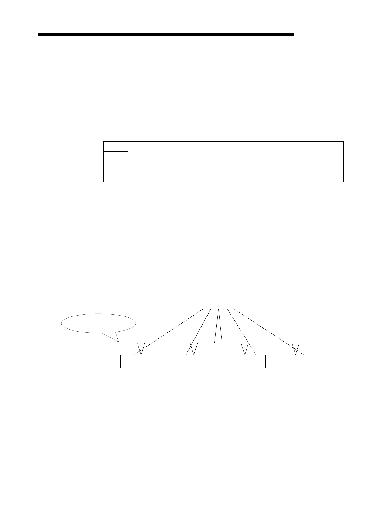
(2) DN91 operates as the DeviceNet master station to permit I/O and message
(3) Each master unit can communicate with up to 63 slave stations.
(4) The communication method for I/O communication can be selected indepen-dently for
DeviceNet network
(5) I/O communication permits communication of 256 bytes of inputs (2048 points) and 256
communications with the DeviceNet slave stations.
each slave station from the following four methods prescribed for DeviceNet: polling, bit
strobe, change of state, and cyclic.
However, only one communication method can be selected for each slave station.
DN91
Polling
Bit strobe
Change of state
Cyclic
Slave station 1 Slave station 2 Slave station 3 Slave station 4
bytes of outputs (2048 points) in the edit mode.
(6) Each message communication can communicate 240-byte message data.
(7) Any of the following two methods may be used to set the DN91 parameters:
• Use TO command of the sequence program to set the parameters.
• Use the configuration software to set the parameters. (Refer to the Section 2.2.3 for
the configuration software.)
1 − 1

1. OUTLINE
MELSEC-A
REMARK
When a network analyzer is connected to monitor the DeviceNet network, DN91 is recognized as a product
of the Hilscher company.
1 − 2
1. OUTLINE
1.2 Communication Outline
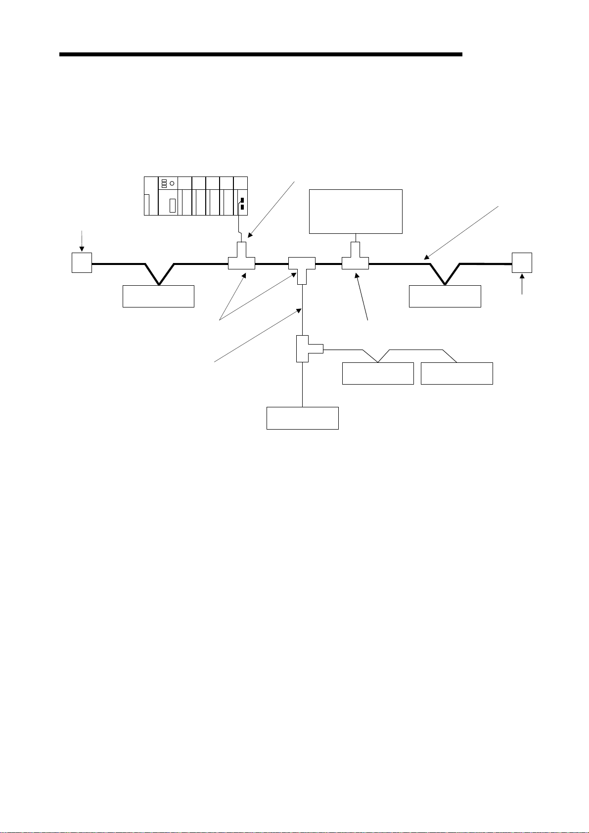
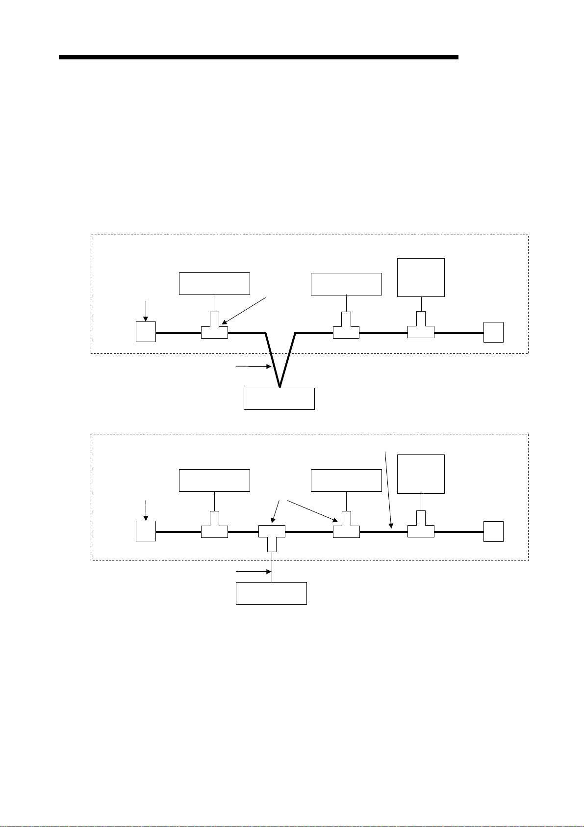
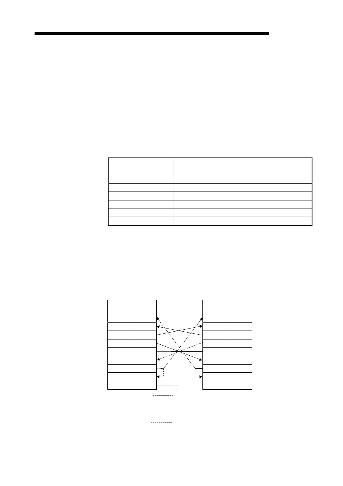
1.2.1 Network configuration
The DN91-based DeviceNet network is configured as shown below.
MELSEC-A
Termination
resistance
Master station
Slave station Slave station
Tap
Drop line (branch)
Drop line
Network power
supply unit
(24 VDC)
Power tap
Slave station Slave station
Slave station
Trunk line
Termination
resistance
1) Up to 64 units can be connected including the master station (DN91) and slave stations.
2) The positions of the master station and slave stations are not fixed. They can be arranged
at any position on the network.
3) The network comprises trunk lines and drop lines.
A termination resistance must be connected to each end of a trunk line.
4) A network power supply must be connected to supply power to the network communication circuits in each station.
1 − 3

1. OUTLINE
MELSEC-A
(1) Network Specifications
This section describes the network specifications of a DeviceNet using DN91.
(a) Communication Speed
The communication speed can be selected as 125, 250, or 500 kbaud using a
sequence program or a configuration software.
The maximum cable length depends on the communication speed. See 3.2
Performance Specifications for details.
(b) Network Power Supply Methods
The following methods are available to supply network power to each station:
1) Connect a dedicated power tap to the trunk line cable and connect a network
power supply unit to it.
2) Supply power from the network power supply unit through network cables to
each station.
REMARK
Contact ODVA or the ODVA Japan office for inquiries about the following devices required for the
DeviceNet network configuration:
• Network power supply unit
• Power tap
• Tap
• Termination resistance
• Cable
Contact Details for ODVA
Open DeviceNet Vender Association, Inc.
Address
8222 Wiles Road, Suite 287, Coral Springs, FL 33067 USA
TEL.305-340-5412 FAX.305-340-5413
ODVA Japan Office
Address
The Japan Chapter of ODVA
Kyoto Research Park 17, Chudoji Minami-Machi, Shimogyo Kyoto 600-8813 Japan
TEL.075-315-9175 FAX.075-315-2898
1 − 4
1. OUTLINE
1.2.2 Outline of parameter settings
Parameter setting is required in advance to communicate with slave stations.
The parameters include DeviceNet communication speed, station number (MAC ID) of DN91,
the number of I/O points of slave stations etc.
They are set in any of the following methods and stored in separate areas of E2PROM inside
DN91.
• Use the sequence program.
• Use the configuration software.
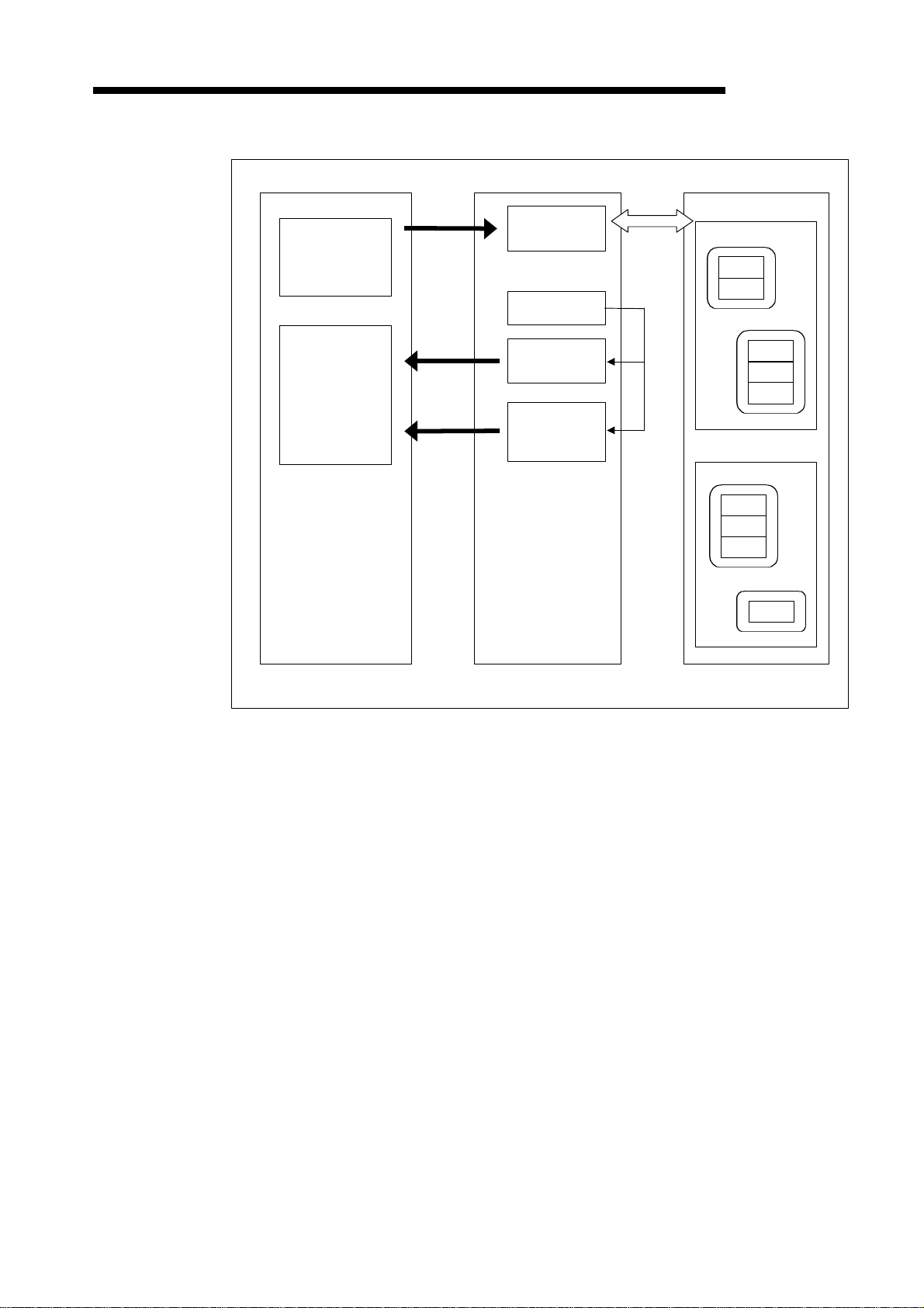
1.2.3 Outline of DN91 - slave station communication
Communication between the DN91 and slave stations is outlined below.
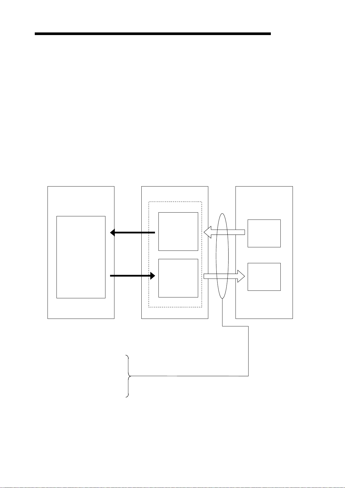
(1) Outline of I/O Communication
I/O communication is a function to communicate I/O data with slave stations.
An outline of I/O communication is shown below.
See 4.1 I/O Communication Functions for details.
Buffer memory
MELSEC-A
Slave stationDN91PLC CPU
Device
FROM
X, Y, M, D, R
TO
Input data area
(Up to 2048
points)
Output data area
(Up to 2048
points)
Input
Output
The following four I/O communication methods are available:
One of these four communication methods can be chosen to match the specification of each slave station.
1) Bit strobe
2) Polling
3) Change of state
4) Cyclic
1 − 5
1. OUTLINE
Message
Message
MELSEC-A
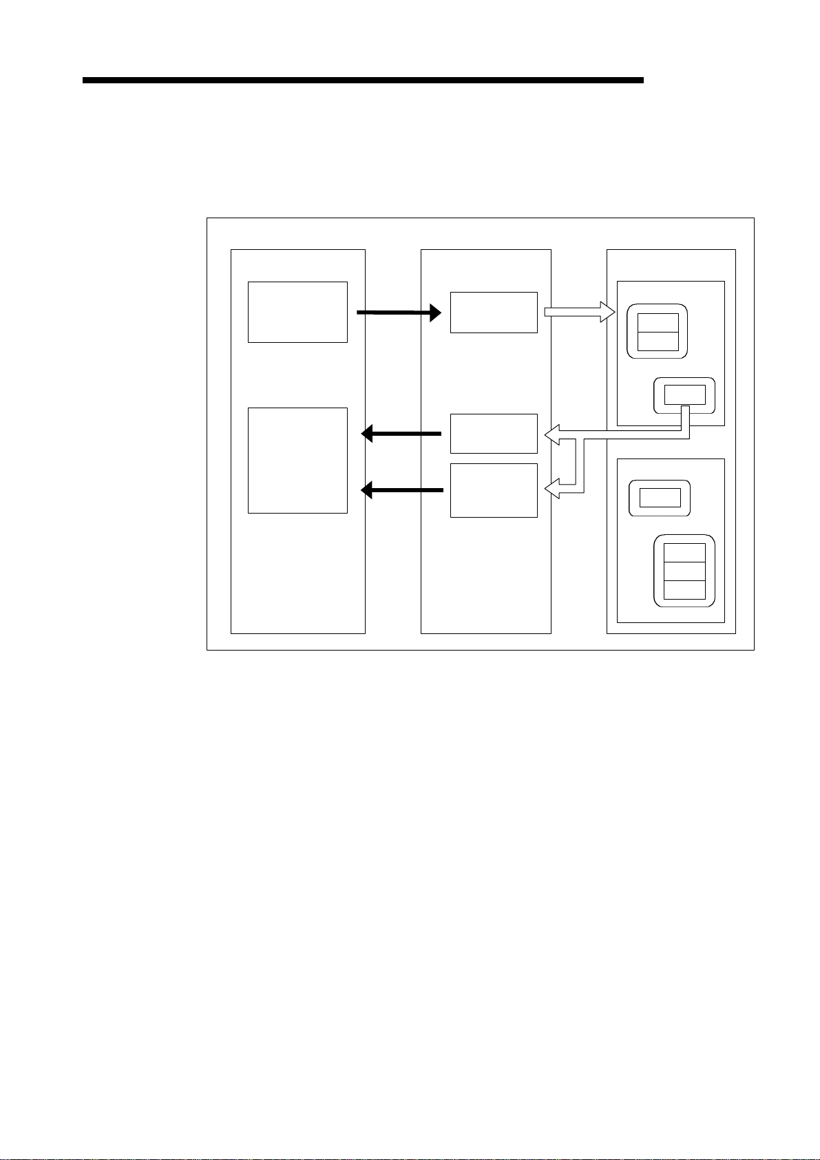
(2) Outline of Message Communication
Message communication is a function to read and write slave station attribute data.
An outline of message communication is shown below. See 4.2 Message Communication
Functions for details.
(a) Reading attributes
Slave stationDN91PLC CPU
Device Class
D, R
Device
D, R
TO
FROM
FROM
communication
command area
Message
communication
result area
communication
data area
(Up to 240 byte)
Instance
Attribute
Attribute
Instance
Attribute
Class
Instance
Attribute
Instance
Attribute
Attribute
Attribute
1 − 6
1. OUTLINE
Message
MELSEC-A
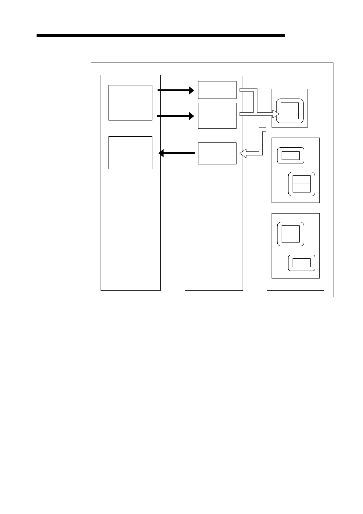
(b) Writing attributes
Slave stationDN91PLC CPU
Device
D, R
Device
D, R
TO
TO
FROM
communication
command area
Message
communication
data area
(Up to 240 byte)
Message
communication
result area
Class
Instance
Attribute
Attribute
Class
Instance
Attribute
Instance
Attribute
Attribute
Class
Instance
Attribute
Attribute
Instance
Attribute
1 − 7
1. OUTLINE
I/O
Device
Device
MELSEC-A
(c) Reading communication error information
D, R
D, R
TO
FROM
FROM
DN91PLC CPU
Message
communication
command area
Slave information
storage area *
Message
communication
result area
Message
communication
data area
(Up to 240 byte)
communi-
cation
Slave station
Class 1
Instance
Attribute
Attribute
Instance
Attribute
Attribute
Attribute
Class
Instance
Attribute
Attribute
Attribute
Instance
Attribute
*: Stores the status of each slave station during I/O communication.
1 − 8
2. SYSTEM CONFIGURATION
2. SYSTEM CONFIGURATION
This section describes the system configuration on DeviceNet.
2.1 Overall Configuration
A master station can communicate with up to 63 slave stations.
Each station is connected via a tap on the trunk line or is directly connected to the trunk line.
The system configuration using AJ71DN91/A1SJ71DN91 as the master station is described
below.
2.1.1 A typical system configuration that connects with a trunk line
Termination
resistance
Slave station
Tap
Slave station
MELSEC-A
Slave stations: max. 63
stations
Power
supply: 24
VDC
Trunk line
Master station
DeviceNet master unit
AJ71DN91/A1SJ71DN91
2.1.2 A typical system configuration that connects with a drop line
Termination
resistance
Tap
Drop line
Master station
Slave stationSlave station
DeviceNet master unit
AJ71DN91/A1SJ71DN91
Trunk line
Slave stations: max. 63
stations
Power
supply: 24
VDC
2 − 1
2. SYSTEM CONFIGURATION
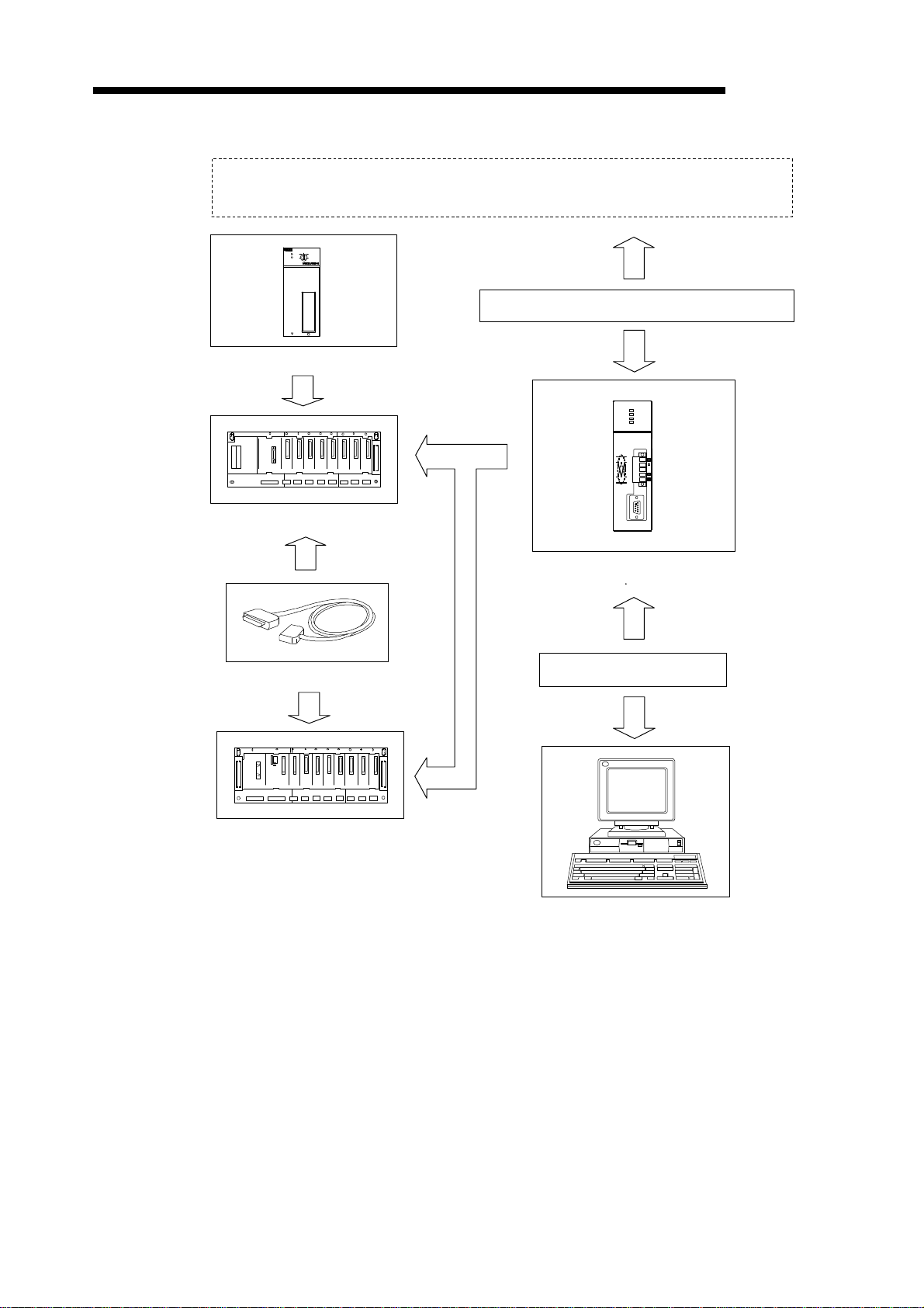
2.1.3 System configuration with a DeviceNet master unit
DeviceNet network
A
CPU
S1
STOP
RUN
L.CLR
RUN
ERROR
RESETRESET
CPU
PULL
PLC CPU
Trunk line or drop line
A1SJ71DN91
RUN
L.RUN
MS
NS
DeviceNet
MELSEC-A
Main base
Extension Cable
Extension base
RS-232-C
DeviceNet master unit
AJ71DN91 A1SJ71DN91
RS-232C cross-cable
Configuration unit (*)
*: PC/AT-compatible computer + configuration software
2 − 2
2. SYSTEM CONFIGURATION
2.2 Applicable Systems
This section describes important points regarding which CPU units can be used and the
system configuration.
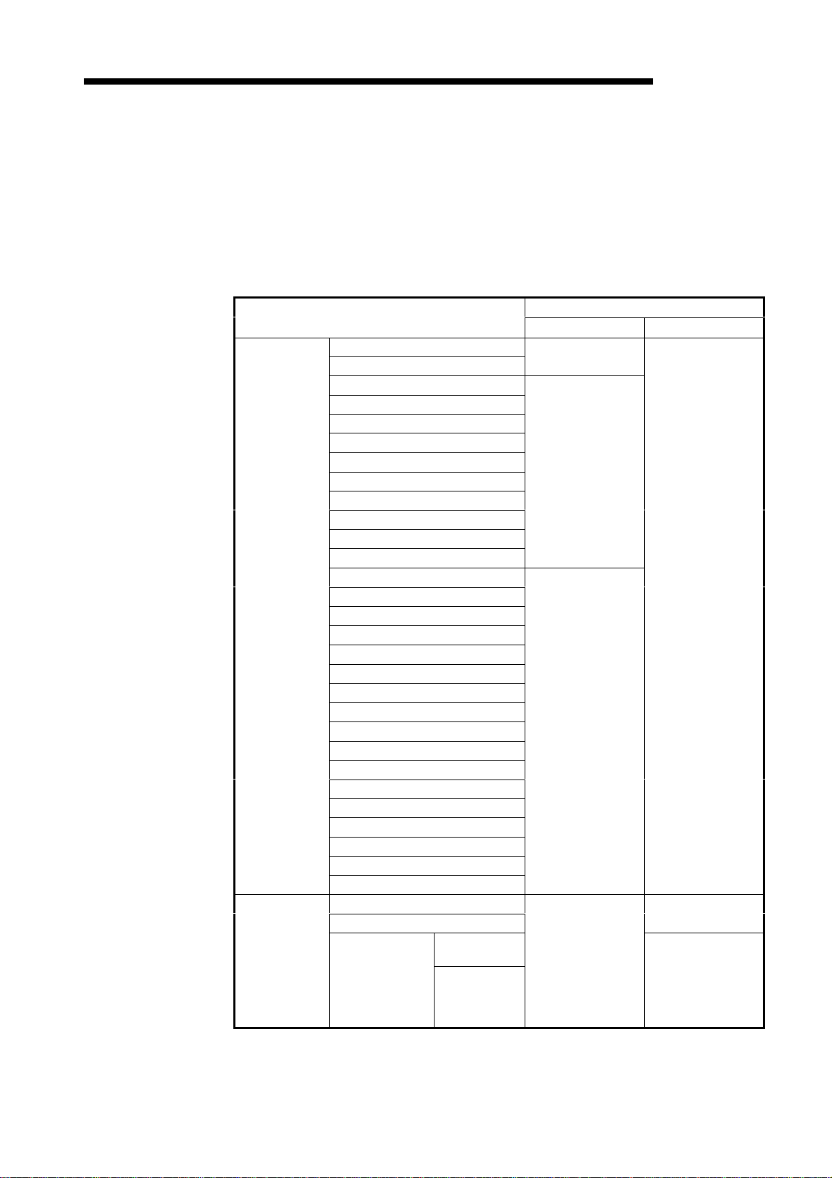
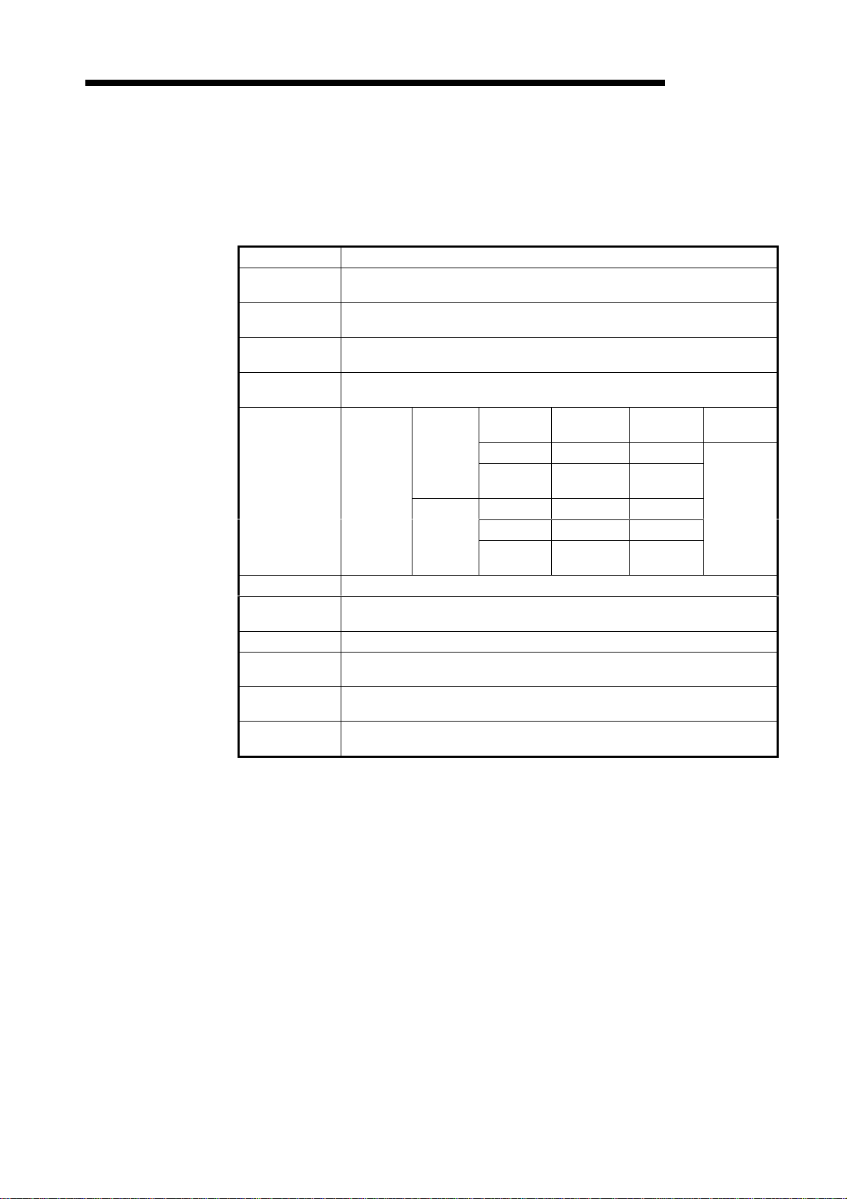
2.2.1 Mountable CPUs and number of units
Table 2.1 shows which PLC CPUs can be mounted and the number of units.
Mounting Position
A0J2CPU
A0J2HCPU
A1SCPU(S1)
A1SHCPU
A1SJCPU(S3)
A1SJHCPU(S8)
A1SCPUC24-R2
A2SCPU(S1)
A2SHCPU(S1)
A2ASCPU(S1/S30)
Q2ASCPU(S1)
Q2ASHCPU(S1)
A1CPU
A2CPU(S1)
PLC CPU
Data link and
network
A3CPU
A1NCPU
A2NCPU(S1)
A3NCPU
A3MCPU
A3HCPU
A2ACPU(S1)
A3ACPU
A2UCPU(S1)
A3UCPU
A4UCPU
Q2ACPU(S1)
Q3ACPU
Q4ACPU
Q4ARCPU
MELSECNET remote I/O station
MELSECNET/B remote I/O station
MELSECNET/10
remote I/O station
Table 2.1 Mountable CPUs and Number of Units
Number of Mountable Units
A1SJ71DN91 AJ71DN91
Cannot be used
No restriction
Cannot be used
AJ72LP25
AJ72BR15
A1SJ72QLP25
AJ72QLP25
A1SJ72QBR15
AJ72QBR15
Cannot be used
MELSEC-A
No restriction
Cannot be used
No restriction
2 − 3

2. SYSTEM CONFIGURATION
2.2.2 Important points about the system configuration
This section gives some important points about configuration of a DeviceNet network system.
(1) Maximum Number of Units
Units up to the number of CPU I/Os may be installed. The DN91 uses 32 I/O points and
one slot.
(2) Applicable Base Units
The DN91 can be mounted in any main base unit or extension base unit slot, with the
following exceptions.
(a) Avoid mounting the DN91 in an extension base unit with no power supply (A5 B,
A1S5 B extension base unit) as the power supply capacity may be insufficient.
If the DN91 is mounted in this type of unit, select the power supply unit and
extension cable with due consideration to the current capacity of the power supply
unit and the voltage drop in the extension cable.
See the user's manual of your PLC CPU for details.
(b) The DN91 cannot be mounted in the final slot of the A3CPU(P21/R21) expansion
7th stage.
MELSEC-A
(3) Not Mountable in MELSECNET(II), MELSECNET/B Remote I/O Station
DN91 cannot be mounted in a MELSECNET(II), MELSECNET/B remote I/O station.
(4) Cautions When Connecting Wiring
To avoid noise interference, separate DeviceNet communication cables, power cables,
and I/O unit signal cables.
(5) No Remote Operation from Another Node
It is not enabled to read, write, or monitor the sequence program of the PLC CPU, which
contains the DN91, and the data of slave stations via nodes on the DeviceNet.
2 − 4
2. SYSTEM CONFIGURATION
2.2.3 Operating environment of the configuration software (parameter setting tool)
This section describes the operating environment when setting DN91 parameters with the
configuration software.
The configuration software is a peripheral device which installs the following configuration
software in a personal computer to allocate communication data for each slave station to the
DeviceNet master station.
(1) Configuration Software
SyCon Ver. 2.0.6.2 or later (Include DLL file Ver. 2.5.0.1 or later.)
(2) Operating Environment of the Configuration Software
The operating environment is shown below.
Table 2.2 Operating Environment
Item Environment
Personal computer PC/AT compatible personal computer
CPU Intel 486 processor, or above
OS Windows95, WindowsNT3.51, WindowsNT4.0 *
Free disk space 10 Mbyte min.
RAM 16 Mbyte min.
Display resolution 800 x 600 dot, min.
External storage CD-ROM drive (for installation only)
MELSEC-A
*: Registered trademark of Microsoft Corporation.
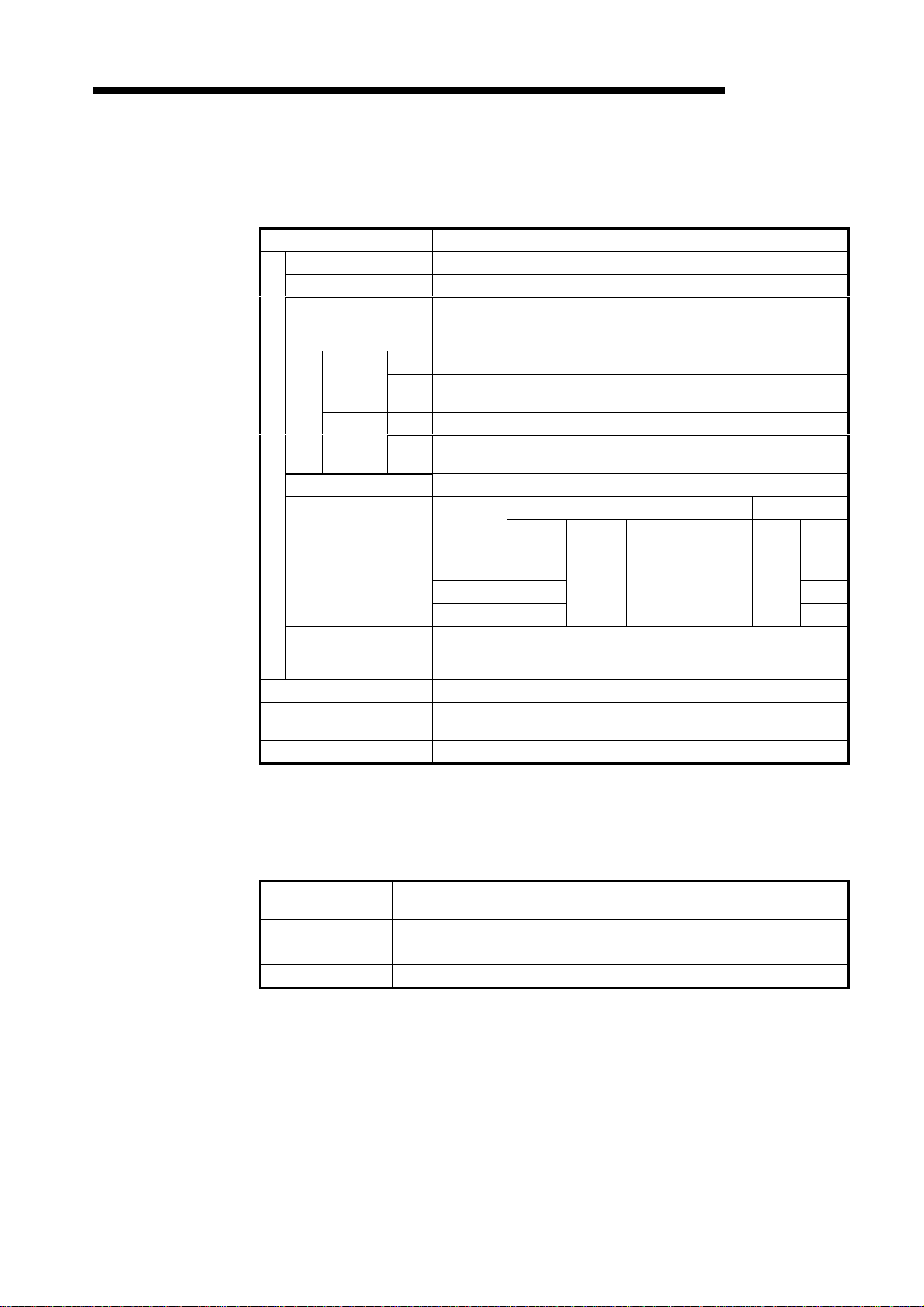
(3) RS-232C Cross-cable
The wiring connections of the RS-232C cross-cable which links the PC/AT-compatible
personal computer and DN91 are shown below.
A(1S)D53DN15Dsub
female connector
(9 pin)
Signal
Name
1 1 DCD
RD 2 2 RxD
SD 3 3 TxD
DTR 4 4 DTR
SG 5 5 GND
6 6 DSR
RS 7 7 RTS
CS 8 8 CTS
9 9 RI
Pin
Number
not connected
PC/AT-compatible
PC Dsub female
connectors
(9 pin)
Pin
Number
Signal
Name
• Shielded cable is recommended.
• Connection of is recommended to eliminate directionality.
2 − 5

2. SYSTEM CONFIGURATION
REMARK
Configurator suppliers are listed below.
• USA
Synergetic Micro Systems, Inc.
2506 Wisconsin Ave.
Downers Grove, IL USA 60515
TEL: +1-630-434-1770
FAX: +1-630-434-1987
• Germany
Hilscher Gesellschaft füE Systemautomation GmbH
Rheinstrasse 78
D-65795 Hattersheim
Germany
TEL: +49-6190-9907-0
FAX: +49-6190-9907-50
• Japanese Agent
NPS Ltd.
4F Shinjuku No. 7 Hayama Building
1-36-2 Shinjuku
Shinjuku-ku
Tokyo
TEL: 03-3226-8110
FAX: 03-3226-8113
MELSEC-A
2.3 Products Connectable to a Slave Station
While it is considered connectable with most commercially available DeviceNet products, we
cannot guarantee the connectivity with products of other manufa-cturers.
2 − 6
3. SPECIFICATIONS
3. SPECIFICATIONS
3.1 General Specifications
Table 3.1 shows the general specifications of the DN91.
Operating ambient
temperature
Operating ambient
humidity
Storage ambient
temperature
Storage ambient
humidity
Vibration
resistance
Shock resistance Conforming to JIS B 3501, IEC 1131-2 (147 m/s2 {15G}, 3 times in 3 directions)
Operating
environment
Operating altitude 2000 m max.
Installation
position
Over-voltage
category
Degree of
contamination
Table 3.1 General Specifications
Item Specification
0 to 55 °C
10 to 90 %RH, no condensation
- 20 to 75 °C
10 to 90 %RH, no condensation
Frequency Acceleration Amplitude
Intermittent
Conforming
to JIS
B3501,
IEC1131-2
*3
*1
*2
vibrations
Continuous
vibrations
10 to 57 Hz 0.075 mm
57 to 150 Hz
Frequency Acceleration Amplitude
10 to 57 Hz 0.035 mm
57 to 150 Hz
No corrosive gas
In control box
9.8 m/s
{1G}
4.9 m/s
{0.5G}
II max.
2 max.
MELSEC-A
Number of
Sweeps
2
2
10 in X, Y,
and Z
directions
(80 minutes)
*1: Indicates the position of the distribution board to which the device is assumed to be connected
between the public power network and the position of the machine in the factory.
Category II is applicable to devices supplied by power from fixed plant.
For devices rated up to 300 V, surge-voltage resistance is 2500 V.
*2: Indicator showing the degree of generation of conducting material in the device operating
environment.
A degree of contamination of 2 indicates that only non-conducting contamination occurs. However,
temporary conductivity may arise in this environment due to accidental condensation.
*3: JIS (Japanese Industrial Standard)
3 − 1
3. SPECIFICATIONS
3.2 Performance Specifications
Table 3.2 shows the general specifications of the DN91.
By node type Group 2 dedicated client
Settable station numbers 0 to 63
Maximum number of
slave stations to
communicate with
Communication speed Select 125 kbaud, 250 kbaud, or 500 kbaud
Communication specification
Max. cable length *
Amperage consumption
(mA) required on the
network
Number of occupied I/Os Special 32 points
Internal current consumption
at 5 VDC (A)
Product weight (kg) A1SJ71DN91: 0.23, AJ71DN91: 0.43
Table 3.2 Performance Specifications
Item Specification
I/O
communication
volume
Message
communication
Communication data
Send 2048 points (256 bytes)
Re-
ceive
Send 240 bytes
Re-
ceive
Communi-
cation
Speed
125 kbaud 500 m 156 m
250 kbaud 250 m 78 m
500 kbaud 100 m
Trunk Line Max. Transfer Distance Drop Line
Thick
Cable
2048 points (256 bytes)
Thin
Cable
100 m See 3.2.1 6 m
63
240 bytes
Thick Cable/Thin
Cable Combination
26.5
0.24
MELSEC-A
Max. Total
39 m
*: See the DeviceNet Specifications (Release 2.0) Volume 1 and Volume 2 for details about the
maximum cable lengths.
3.2.1 Maximum transfer distance of a trunk line that contains both thick and thin cables
This section shows the maximum transfer distances for thick cable/thin cable com-binations.
Communication
Speed
125 kbaud (Thick cable length + 5) x thin cable length ≤ 500 m
250 kbaud (Thick cable length + 2.5) x thin cable length ≤ 250 m
500 kbaud Thick cable length x thin cable length ≤ 100 m
Trunk Line Max. Transfer Distance with a Thick Cable/Thin Cable
Combination
3 − 2

3. SPECIFICATIONS
3.3 PLC CPU I/O Signals
This section describes the I/O signals for the DN91 PLC CPU.
3.3.1 Table of I/O signals
Table 3.3 shows the table of DN91 I/O signals.
The letter "n" in the table represents the leading I/O number of DN91. It is determin-ed by the
position installed and the unit installed before DN91.
<Example> If the DN91 head I/O number is "X/Y30"
Input Number Signal Name Output Number Signal Name
MELSEC-A
Xn0 to X(n+1)F → X30 to X4F
Yn0 to Y(n+1)F → Y30 to Y4F
Table 3.3 Table of I/O Signals
DN91 →→ PLC CPU PLC CPU →→ DN91
Xn0 Watchdog timer error Yn0
Xn1 Refreshing Yn1
Xn2
Xn3 Error set signal Yn3
Xn4 Slave down signal Yn4
Xn5
Xn6 Parameter being set Yn6
Xn7 Parameter setting complete Yn7
Xn8 Yn8
Xn9 Yn9
XnA YnA
XnB YnB
XnC YnC
XnD YnD
XnE
XnF Unit ready YnF
X(n+1)0 Y(n+1)0 Unusable
X(n+1)1 Y(n+1)1 Refresh request
X(n+1)2 Y(n+1)2
X(n+1)3 Y(n+1)3 Error reset request
X(n+1)4 Y(n+1)4
X(n+1)5 Y(n+1)5
X(n+1)6 Y(n+1)6
X(n+1)7 Y(n+1)7 Parameter set request
X(n+1)8 Y(n+1)8
X(n+1)9 Y(n+1)9
X(n+1)A Y(n+1)A
X(n+1)B Y(n+1)B
X(n+1)C Y(n+1)C
X(n+1)D Y(n+1)D
X(n+1)E Y(n+1)E
X(n+1)F
Message communication
complete
Message communication error
signal
Unusable
Unusable
Yn2
Yn5
Unusable
YnE
Message communication
request
Unusable
Unusable
Y(n+1)F
3 − 3

3. SPECIFICATIONS
Important
MELSEC-A
The output signals designated as "unusable" in Table 3.3 are reserved for system use
and are not available to the user. Normal operation cannot be guaranteed if the user
operates one of these output signals (that is, turns the signal ON or OFF).
3 − 4
3. SPECIFICATIONS
3.3.2 I/O signal details
This section explains the I/O signal ON/OFF timing and conditions.
(1) Watchdog timer error: Xn0
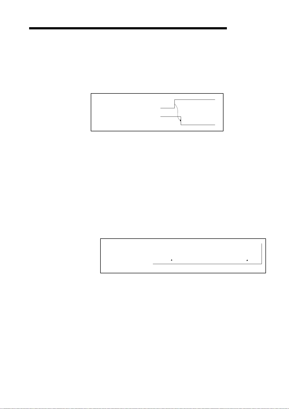
(2) Refreshing: Xn1, Refresh request: Y(n+1)1
MELSEC-A
Turns ON if an error occurs in DN91.
OFF: Unit normal
ON: Unit abnormal
Watchdog timer error (Xn0)
Unit ready (XnF)
These signals determine whether the data in the input data area and output data area of
the buffer memory is used to refresh the network.
Refresh is conducted if the status of the master communication status area in buffer
memory is "operation in progress."
(a) To start the data refresh, turn ON refresh request (Y(n+1)1) with a sequen-ce
program.
(b) When refresh request (Y(n+1)1) is turned ON, the refresh operation starts and
refreshing (Xn1) turns ON automatically.
(c) To stop the data refresh, turn OFF refresh request Y(n+1)1 with a sequen-ce
program.
(d) The data refreshing is interrupted with "Refreshing" signal (Xn1) turned OFF
automatically and "OFF" or 0 data transmitted to all slave stations.
Refreshing the input data area still continues.
Refresh request (Y(n+1)1)
Refreshing (Xn1)
3 − 5
3. SPECIFICATIONS
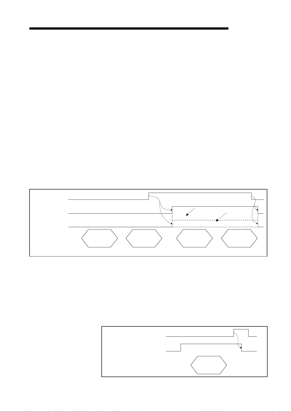
(3) Message communication complete : Xn2
MELSEC-A
Message communication error signal : Xn5
Message communication request : Y(n+1)2
These signals are used for message communication. Message communication is
conducted if the status of the master communication status area in buffer memory is
"operation in progress."
(a) Follow the procedure below to conduct message communication.
1) Write the message communication data to the message communication
command area in buffer memory.
2) Turn ON message communication request (Y(n+1)2) with a sequence program.
(Set the interval of turning ON the message communication request at 100 ms
or over.)
(b) The message communication completes with the results written onto the "Message
communication results" area, and the message communication complete (Xn2)
turns ON.
(c) Check the results of the message communication through the message
communication error signal (Xn5).
Message communication
request (Y(n+1)2)
Message communication
complete (Xn2)
Message communication
error signal (Xn5)
FROM/TO
(d) After reading the communication data with FROM command, the sequence program
is used to turn OFF the message communication request (Y(n+1)2).
The message communication complete (Xn2) and message communication error
signal (Xn5) automatically turns OFF.
Write message
communication
command (TO
instruction)
Error involved
Write message
communication
data (TO
instruction)
(For data send only) (For data receive only)
Read message
communication
results (FROM
instruction)
No error
Read message
communication
data (FROM
instruction)
(4) Error set signal: Xn3, Error reset request: Y(n+1)3
These signals are used to notify an error and reset error codes.
(a) If an error occurs, error information is stored in the error information area in buffer
memory and the error set signal (Xn3) turns ON.
The error set signal automatically turns OFF when the cause of the error is
removed.
(b) Once the cause of error is removed, turning ON the error-resetting request
(Y(n+1)3) with the sequence program clears the error code set on the "error
information" area.
Error reset request (Y(n+1)3)
Error set signal (Xn3)
FROM/TO
3 − 6
Read error
information (FROM
instruction)
3. SPECIFICATIONS
(5) Slave down signal: Xn4
(6) Parameter-being-set : Xn6
MELSEC-A
This signal indicates whether any slave station has stopped communication.
(a) This signal turns ON if any slave station for which parameters are set stops
communication.
OFF : All stations communicating normally
ON : Abnormal communication at a station
Which station has stopped communication can be confirmed from the station
communication status area at addresses 01BCH to 01BFH of the buffer memory.
(b) This signal automatically turns OFF when the slave station communication restarts.
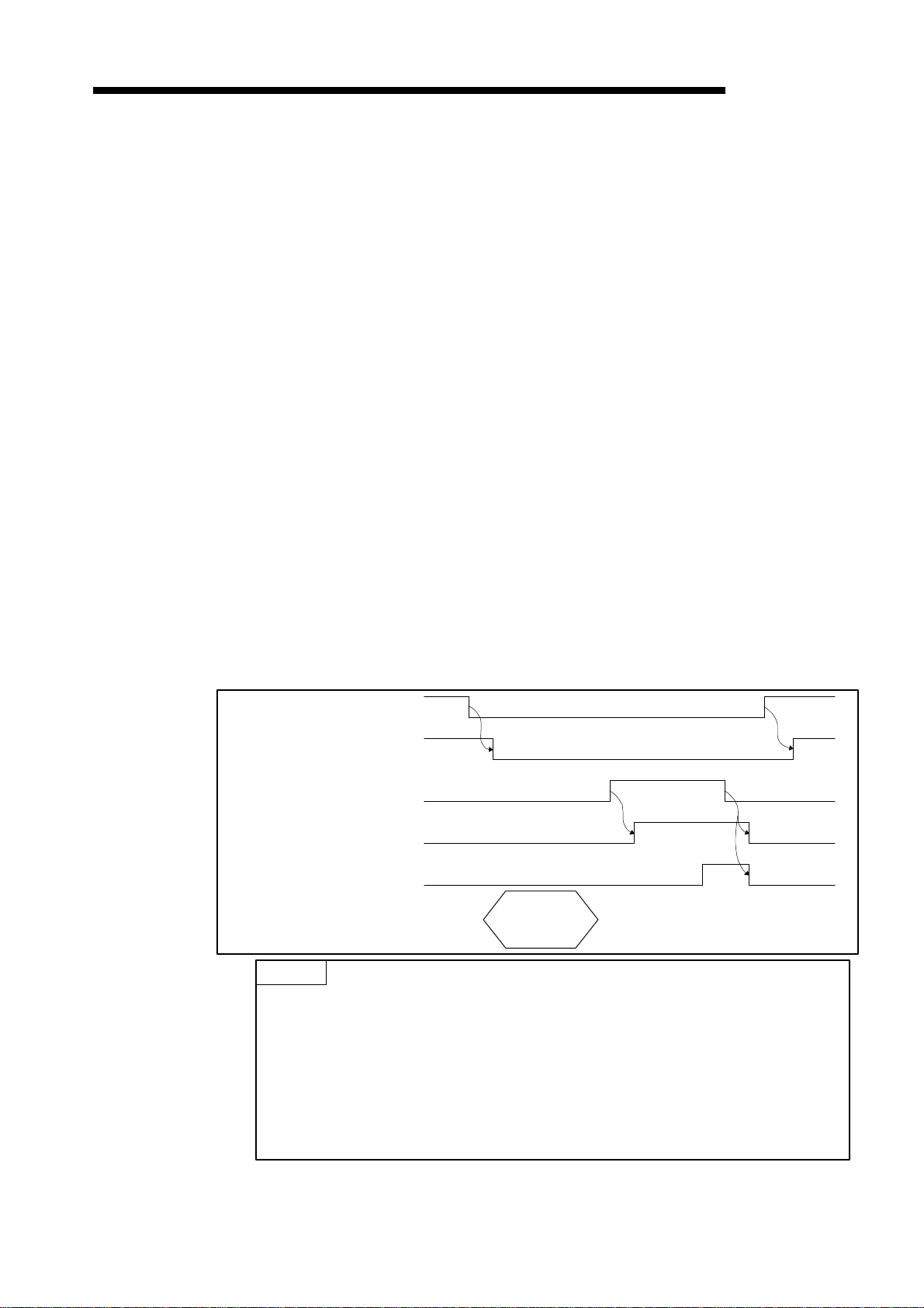
Parameter set complete : Xn7
Parameter set request : Y(n+1)7
These signals are used to set parameters with a sequence program. Set the parameters
when the refreshing (Xn1) signal is OFF.
(a) Follow the procedure below to write parameters.
1) Write the parameters to the parameter set area in buffer memory.
2) Turn on parameter set request (Y(n+1)7) with a sequence program.
(b) Once the write request is received and the parameter analysis completes normally,
parameter-writing action gets executed with the parameter-being-set (Xn6) turned
ON.
(c) Parameter set complete (Xn7) automatically turns ON when the parameter write
operation is complete. Communication with other slave stations is disabled while
parameters are being set.
Parameter set complete (Xn7) automatically turns OFF when parameter set request
(Y(n+1)7) turns OFF.
Refresh request (Y(n+1)1)
Refreshing (Xn1)
Parameter set request (Y(n+1)7)
Parameter being set (Xn6)
Parameter set complete (Xn7)
TO instruction
POINTS
(1) If refreshing (Xn1) is ON when parameter set request (Y(n+1)7) turns ON,
parameter set complete (Xn7) does not turn ON. First, turn OFF refresh request
(Y(n+1)1) and confirm that refreshing (Xn1) is OFF before turning parameter set
request (Y(n+1)7) OFF and back ON.
(2) If parameter set request (Y(n+1)7) is ON when refresh request (Y(n+1)1) turns ON,
refreshing (Xn1) does not turn ON. First, turn OFF parameter set request
(Y(n+1)7), then reset refresh request (Y(n+1)1) and turn it back ON.
Write parameter
data
3 − 7
 Loading...