

Page 1

Page 2

Page 3
SAFETY PRECAUTIONS
(Always read these precautions before using this equipment.)
Before using this product, please read this manual and the relevant manuals introduced in this manual
carefully and pay full attention to safety to handle the product correctly.
The precautions given in this manual are concerned with this product.
In this manual, the safety precautions are ranked as "DANGER" and "CAUTION".
DANGER
CAUTION
Note that the caution level may lead to a serious accident according to the circumstances. Always follow
the instructions of both levels because they are important to personal safety.
Please save this manual to make it accessible when required and always forward it to the end user.
Indicates that incorrect handling may cause hazardous
conditions, resulting in death or severe injury.
Indicates that incorrect handling may cause hazardous
conditions, resulting in medium or slight personal injury or
physical damage.
[DESIGN PRECAUTIONS]
DANGER
Some failures of the GOT, communication unit or cable may keep the outputs on or off.
An external monitoring circuit should be provided to check for output signals which may lead to a
serious accident.
Not doing so can cause an accident due to false output or malfunction.
If a communication fault (including cable disconnection) occurs during monitoring on the GOT,
communication between the GOT and PLC CPU is suspended and the GOT becomes inoperative.
For bus connection: The CPU becomes faulty and the GOT becomes inoperative.
For other than bus connection: The GOT becomes inoperative.
A system where the GOT is used should be configured to perform any significant operation to the
system by using the switches of a device other than the GOT on the assumption that a GOT
communication fault will occur.
Not doing so can cause an accident due to false output or malfunction.
Do not use the GOT as the warning device that may cause a serious accident.
An independent and redundant hardware or mechanical interlock is required to configure the device
that displays and outputs serious warning.
Failure to observe this instruction may result in an accident due to incorrect output or malfunction.
A - 1
Page 4
[DESIGN PRECAUTIONS]
DANGER
Incorrect operation of the touch switch(s) may lead to a serious accident if the GOT backlight is gone
out.
When the GOT backlight goes out, the POWER LED flickers (green/orange) and the display section
turns black and causes the monitor screen to appear blank, while the input of the touch switch(s)
remains active.
This may confuse an operator in thinking that the GOT is in "screensaver" mode, who then tries to
release the GOT from this mode by touching the display section, which may cause a touch switch to
operate.
Note that the following occurs on the GOT when the backlight goes out.
•The POWER LED flickers (green/orange) and the monitor screen appears blank
The display section of the GT1595-X is an analog-resistive type touch panel.
If you touch the display section simultaneously in 2 points or more, the switch that is located around
the center of the touched point, if any, may operate.
Do not touch the display section in 2 points or more simultaneously.
Doing so may cause an accident due to incorrect output or malfunction.
CAUTION
Do not bundle the control and communication cables with main-circuit, power or other wiring.
Run the above cables separately from such wiring and keep them a minimum of 100mm (3.94in.)
apart.Not doing so noise can cause a malfunction.
Do not press the GOT display section with a pointed material as a pen or driver.
Doing so can result in a damage or failure of the display section.
[MOUNTING PRECAUTIONS]
DANGER
Be sure to shut off all phases of the external power supply used by the system before mounting or
removing the GOT main unit to/from the panel.
Not doing so can cause the unit to fail or malfunction.
Be sure to shut off all phases of the external power supply used by the system before mounting or
removing the communication unit, printer unit, option function board or multi-color display board
onto/from the GOT.
Not doing so can cause the unit to fail or malfunction.
When installing the multi-color display board, wear an earth band etc. to avoid the static
electricity.Not doing so can cause a unit corruption.
A - 2
Page 5
[MOUNTING PRECAUTIONS]
CAUTION
Use the GOT in the environment that satisfies the general specifications described in this manual.
Not doing so can cause an electric shock, fire, malfunction or product damage or deterioration.
When mounting the GOT to the control panel, tighten the mounting screws in the specified torque
range.
Undertightening can cause the GOT to drop, short circuit or malfunction.
Overtightening can cause a drop, short circuit or malfunction due to the damage of the screws or the
GOT.
When loading the communication unit or printer unit to the GOT, fit it to the connection interface of
the GOT and tighten the mounting screws in the specified torque range.
Undertightening can cause the GOT to drop, short circuit or malfunction.
Overtightening can cause a drop, failure or malfunction due to the damage of the screws or unit.
When mounting the multi-color display board onto the GOT, tighten the mounting screws within the
specified torque range.
Loose tightening may cause the unit and/or GOT to malfunction due to poor contact.
Overtightening may damage the screws, unit and/or GOT; they might malfunction.
Push the option function board onto the corresponding connector until it clicks, so that it will be
secured firmly.
Push the multi-color display board onto the corresponding connector so that it will be secured firmly.
When inserting a CF card into the GOT, push it into the insertion slot until the CF card eject button
will pop out.
Failure to do so may cause a malfunction due to poor contact.
When inserting/removing a CF card into/from the GOT, turn the CF card access switch off in
advance.
Failure to do so may corrupt data within the CF card.
When removing a CF card from the GOT, make sure to support the CF card by hand, as it may pop
out.
Failure to do so may cause the CF card to drop from the GOT and break.
A - 3
Page 6
[WIRING PRECAUTIONS]
DANGER
Be sure to shut off all phases of the external power supply used by the system before wiring.
Failure to do so may result in an electric shock, product damage or malfunctions.
CAUTION
Always ground the FG terminal, LG terminal, and protective ground terminal of the GOT power to the
protective ground conductors dedicated to the GOT.
Not doing so may cause an electric shock or malfunction.
Terminal screws which are not to be used must be tightened always at torque 0.5 to 0.8 N
Otherwise there will be a danger of short circuit against the solderless terminals.
Use applicable solderless terminals and tighten them with the specified torque.
If any solderless spade terminal is used, it may be disconnected when the terminal screw comes
loose, resulting in failure.
Correctly wire the GOT power supply section after confirming the rated voltage and terminal
arrangement of the product.
Not doing so can cause a fire or failure.
Tighten the terminal screws of the GOT power supply section in the specified torque range.
Undertightening can cause a short circuit or malfunction.
Overtightening can cause a short circuit or malfunction due to the damage of the screws or the GOT.
Exercise care to avoid foreign matter such as chips and wire offcuts entering the GOT. Not doing so
can cause a fire, failure or malfunction.
The module has an ingress prevention label on its top to prevent foreign matter, such as wire offcuts,
from entering the module during wiring.
Do not peel this label during wiring.
Before starting system operation, be sure to peel this label because of heat dissipation.
·m.
Plug the communication cable into the connector of the connected unit and tighten the mounting and
terminal screws in the specified torque range.
Undertightening can cause a short circuit or malfunction.
Overtightening can cause a short circuit or malfunction due to the damage of the screws or unit.
Plug the QnA/ACPU/Motion controller (A series) bus connection cable by inserting it into the
connector of the connected unit until it "clicks".
After plugging, check that it has been inserted snugly.
Not doing so can cause a malfunction due to a contact fault.
A - 4
Page 7
[TEST OPERATION PRECAUTIONS]
DANGER
Before performing the test operations of the user creation monitor screen (such as turning ON or
OFF bit device, changing the word device current value, changing the settings or current values of
the timer or counter, and changing the buffer memory current value), read through the manual
carefully and make yourself familiar with the operation method.
During test operation, never change the data of the devices which are used to perform significant
operation for the system.
False output or malfunction can cause an accident.
[STARTUP/MAINTENANCE PRECAUTIONS]
DANGER
When power is on, do not touch the terminals.
Doing so can cause an electric shock or malfunction.
Connect the battery correctly.
Do not discharge, disassemble, heat, short, solder or throw the battery into the fire.
Incorrect handling may cause the battery to generate heat, burst or take fire, resulting in injuries or
fires
Before starting cleaning or terminal screw retightening, always switch off the power externally in all
phases.
Not switching the power off in all phases can cause a unit failure or malfunction.
Undertightening can cause a short circuit or malfunction.
Overtightening can cause a short circuit or malfunction due to the damage of the screws or unit.
A - 5
Page 8
[STARTUP/MAINTENANCE PRECAUTIONS]
CAUTION
Do not disassemble or modify the unit.
Doing so can cause a failure, malfunction, injury or fire.
Do not touch the conductive and electronic parts of the unit directly.
Doing so can cause a unit malfunction or failure.
The cables connected to the unit must be run in ducts or clamped.
Not doing so can cause the unit or cable to be damaged due to the dangling, motion or accidental
pulling of the cables or can cause a malfunction due to a cable connection fault.
When unplugging the cable connected to the unit, do not hold and pull the cable portion.
Doing so can cause the unit or cable to be damaged or can cause a malfunction due to a cable
connection fault.
Do not drop the module or subject it to strong shock.
A module damage may result.
Do not drop or give an impact to the battery mounted to the unit.
Doing so may damage the battery, causing the battery fluid to leak inside the battery.
If the battery is dropped or given an impact, dispose of it without using.
Before touching the unit, always touch grounded metal, etc. to discharge static electricity from
human body, etc.
Not doing so can cause the unit to fail or malfunction.
[BACKLIGHT REPLACEMENT PRECAUTIONS]
DANGER
Be sure to shut off all phases of the external power supply of the GOT (and the PLC CPU in the case
of a bus topology) and remove the GOT from the control panel before replacing the backlight (when
using the GOT with the backlight replaceable by the user).
Not doing so can cause an electric shock.
Replacing a backlight without removing the GOT from the control panel can cause the backlight or
control panel to drop, resulting in an injury.
A - 6
Page 9
[BACKLIGHT REPLACEMENT PRECAUTIONS]
CAUTION
Wear gloves for the backlight replacement when using the GOT with the backlight replaceable by the
user.
Not doing so can cause an injury.
Before replacing a backlight, allow 5 minutes or more after turning off the GOT when using the GOT
with the backlight replaceable by the user.
Not doing so can cause a burn from heat of the backlight.
[DISPOSAL PRECAUTIONS]
CAUTION
When disposing of the product, handle it as industrial waste.
[TRANSPORTATION PRECAUTIONS]
CAUTION
When transporting lithium batteries, make sure to treat them based on the transport regulations.
(Refer to Appendix 3 for details of the regurated units.)
Make sure to transport the GOT main unit and/or relevant unit(s) in the manner they will not be
exposed to the impact exceeding the impact resistance described in the general specifications of this
manual, as they are precision devices.
Failure to do so may cause the unit to fail.
Check if the unit operates correctly after transportation.
A - 7
Page 10
REVISIONS
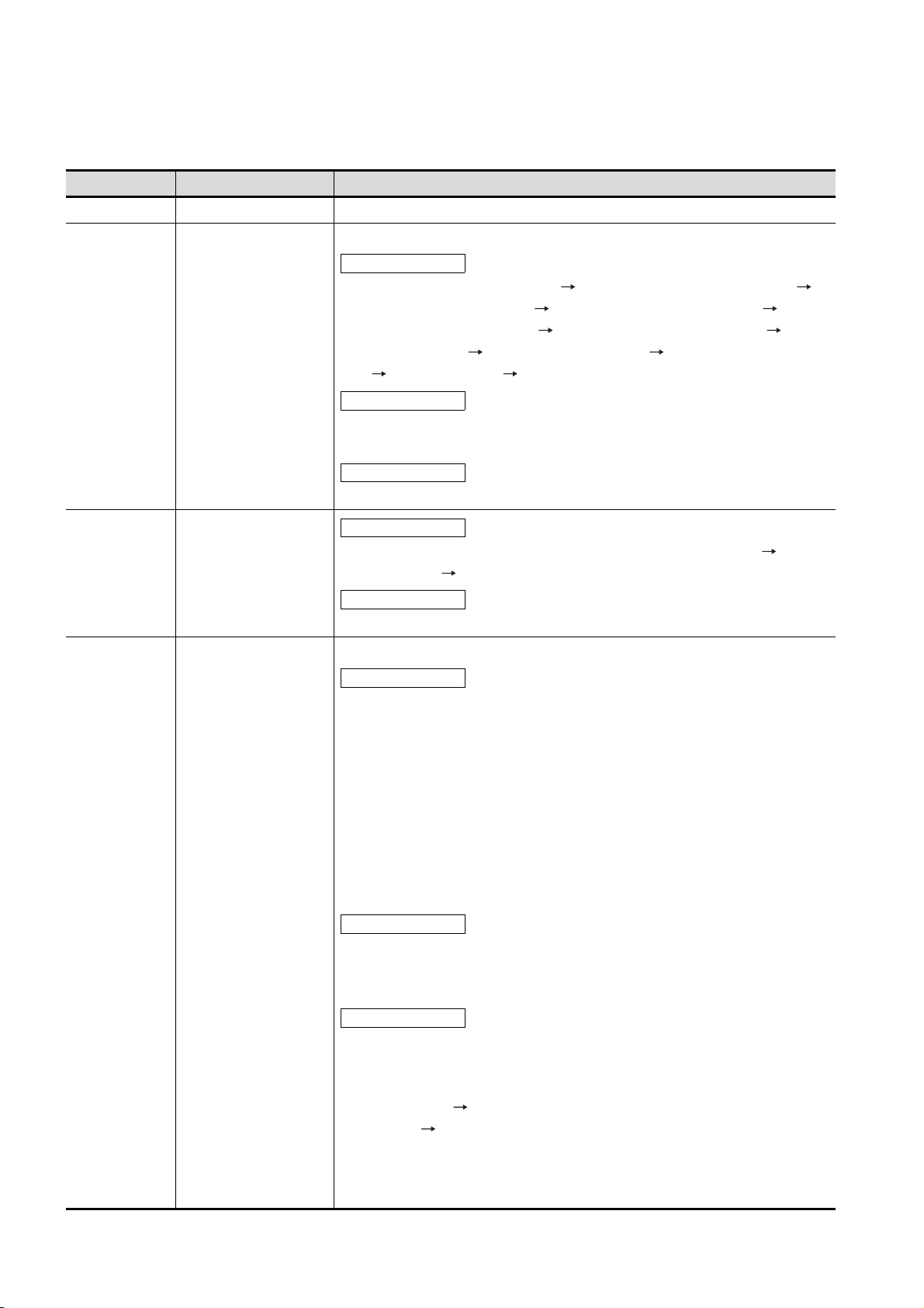
The manual number is given on the bottom left of the back cover.
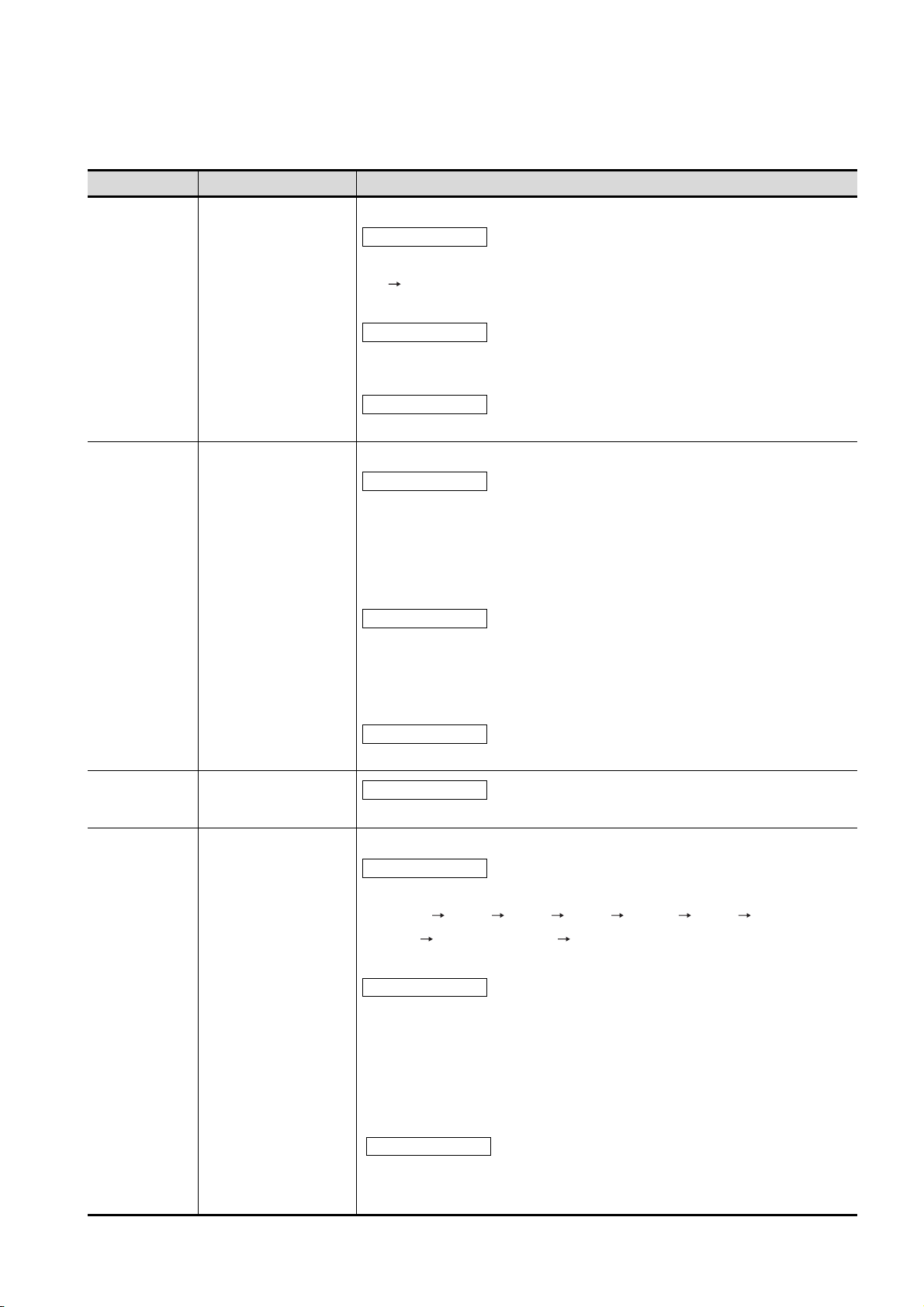
Print Date Manual Number Revision
Oct., 2004 SH(NA)-080528ENG-A First edition
Mar., 2005 SH(NA)-080528ENG-B Compatible with GT Designer2 Version2.09K
Partial corrections
Chapter 6, Section 7.3.2, 8.2 to 8.6 8.2 to 8.4, 8.4.3, Section 9.1 to 9.3
9.1 to 9.2, Section 10.1 to 10.6 10.1 to 10.5, Section 12.1 to 12.6 12.1 to
12.5, Section 13.1, 13.2 to 13.6 13.3 to 13.7, Section 14.1 to 14.2 14.1,
Section 15.1 to 15.2 15.1, Section 16.1 to 16.2 16.1, Chapter 18, Section
18.6 18.3, 18.3 to 18.5 18.4 to 18.6, Section 19.1, 19.2
Partial additions
SAFETY PRECAUTIONS, Section 2.1, 2.2.2, Section 3.2, Section 4.1, 4.2, 4.3,
Section 5.3, Section 7.3.1, 7.5.1, 7.5.2, Section 8.3, Appendix 1, 2, 4
Additions
Section 10.6, Section 12.6, Section 13.2
Apr., 2005 SH(NA)-080528ENG-C
Partial corrections
Section 4.1, 4.2, 4.3, 7.1.2, 7.5.2, 18.6, Appendix 1, Chapter 5 to 19 6 to 20,
Appendix 2 to 4 3 to 5
Sep., 2005 SH(NA)-080528ENG-D
Additions
Chapter 5, Appendix 2
Compatible with GT Designer2 Version 2.18U
Partial corrections
Chapter 1, Section 1.1, 1.2, Section 2.1, 2.2, 2.2.1, 2.2.2, Section 4.1 to 4.4,
Section 5.1, 5.1.3, 5.2.5, 5.4.2, Section 6.3, Section 7, 7.4, Section 8.1, 8.1.1,
8.1.2, 8.2, 8.3, 8.5.1, 8.5.2, 8.6.2, 8.7.3, 8.7.4, 8.11, 8.11.1, Section 9, 9.1, 9.2,
9.3.1, to 9.3.3, Section 10, 10.1.2 to 10.1.4, 10.2.2, 10.2.3, Chapter 11, 11.1,
11.1.1 to 11.1.3, 11.2.2, 11.2.3, 11.3.1, 11.3.2, 11.4.2, 11.5.1 to 11.5.3, Section
12.1.1 to 12.1.3, Section 13, 13.1.2, 13.1.3, 13.2.1, 13.2.2, 13.2.4, 13.3.2 to
13.3.4, 13.4.2, 13.5.2, 13.6.1 to 13.6.3, 13.7, 13.7.1, 13.7.2, 13.7.4, 13.7.5,
Chapter 14, 14.1.2, 14.2.1, 14.3.1 to 14.3.3, 14.4.2, 14.5.2, 14.6.2, 14.7.1,
14.7.2, Section 15.1.2, Section 16.1.3, Section 17.1.3, Chapter 18, 18.1, 18.2,
18.3, 18.3.1, 18.3.2, 18.4, Section 20.1, 20.2, Appendix 5
Partial additions
Section 5.3.2, 5.3.3, Section 6.2, 6.5, Section 8.4.1, 8.7.2, 8.8.1, 8.10.1, 8.10.2,
Section 10.2.1, Section 11.2.1, 11.3.3, Section 13.1.5, Section 14.1.1, Section
19.2, 19.4, 19.5, 19.6.1, 19.6.2, Appendix 1, 3
Additions
Section 3.2.1 to 3.2.4, 3.3.1, 3.3.2, Section 4.1, Section 8.5.3, Section 11.6,
11.8, Section 13.8, 13.9, 13.10, Section 18.5
A - 8
Section 4.1 to 4.3 Section 4.2 to 4.4
Section 11.6 Section 11.7
Page 11
The manual number is given on the bottom left of the back cover.
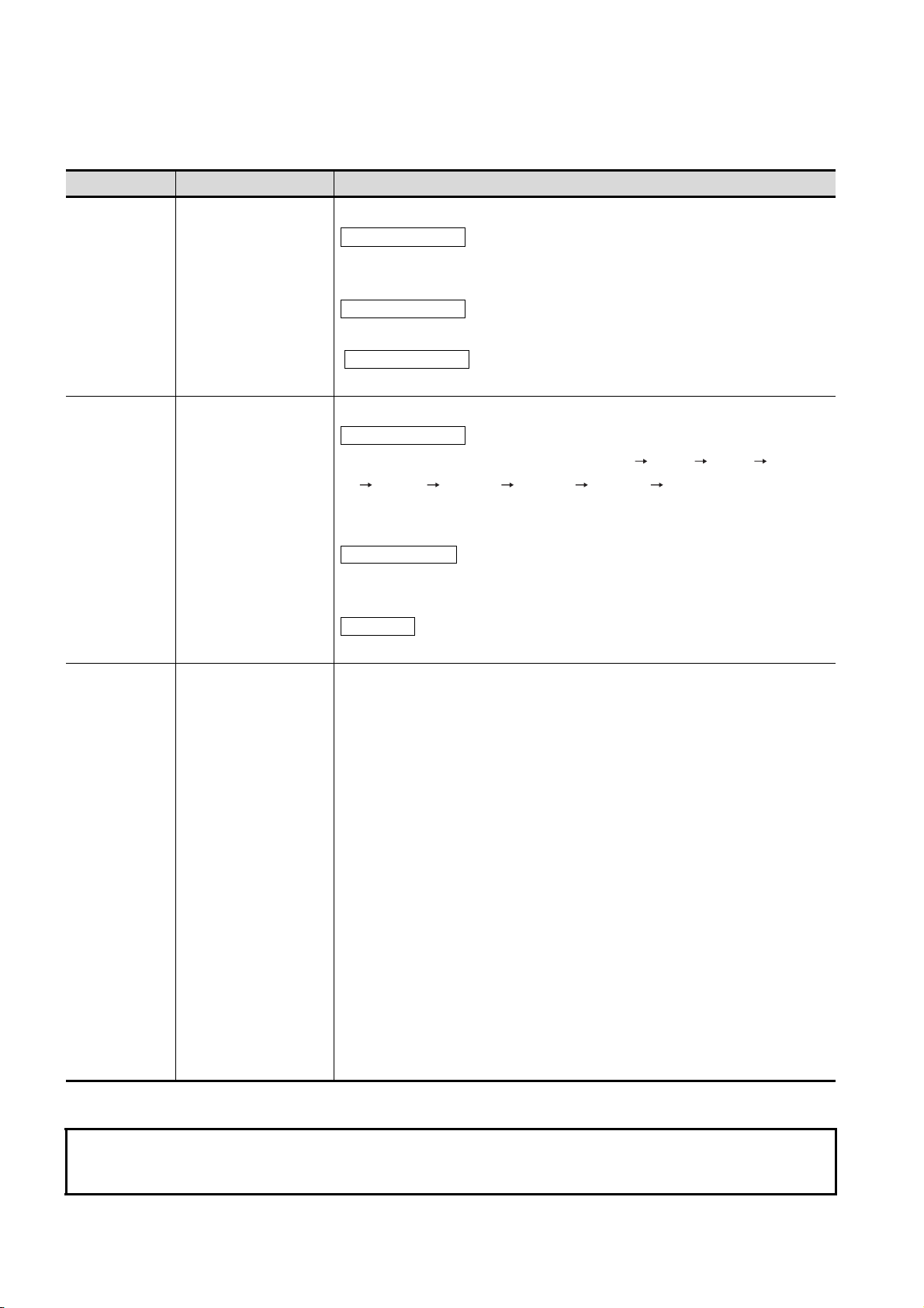
Print Date Manual Number Revision
Jan., 2006 SH(NA)-080528ENG-E Compatible with GT Designer2 Version2.27D
Partial corrections
SAFETY PRECAUTIONS, Chapter 1, Section 2.1, Section 8.1.1, 8.5 to
8.11 8.6 to 8.12, Section 9.2, 9.3, Section 10.1.3, Section 11.1, 11.7.2, Section
13.7.4, 13.10.4
Partial additions
Section 2.2, Section 6.3, Section 13.1.5, 13.2.4, Chapter 14, Section 19.4,
Section 20.2, Appendix 1, 3, 5
Additions
Section 8.5, Section 14.8, 14.9
Jun., 2006 SH(NA)-080528ENG-F Compatible with GT Designer2 Version2.32J
Partial corrections
Chapter 1, Section 1.1, 2.1, 2.2, 4.1, 4.2, 4.3, 4.4, 5.3.1, 5.4.2, 8.4, 8.5.2, 8.9,
9.3, 11.2.2, 11.3.2, 11.4.2, 11.5.2, 11.7.2, 11.8.2, 12.1.3, 13.1.5, 13.2.2, 13.2.3,
13.2.4, 13.3.1, 13.3.3, 13.4.2, 13.4.3, 13.5.2, 13.5.3, 13.6.2, 13.6.3, 13.7.2,
13.7.3, 13.8.2, 13.8.3, 13.9.2, 13.10.2, 13.10.3, 14.3.2, 14.4.2, 14.5.2, 14.6.2,
14.7.2, 14.9, 18.3.1, 18.4, 18.5.2
Partial additions
Chapter 1, Section 2.2.1, 2.2.2, 3.2.1 ~ 3.2.4, 3.3.1, 3.3.2, 5.3.2, 5.3.3, 6.2, 6.3,
7.1, 7.4, 8.1.2, 8.3.1, 8.7, 8.8, 8.10, 8.11, 8.12, 8.13, 9.2, 9.3.1, 10.1.3, Chapter
11, Section 11.1.1, 11.1, 2, 11.5.1, 11.7.1, 11.8.1, Chapter 14, Section 14.1.1,
14.2.1, 19.6.1, 20.2, Appendix 1, 3, 5
Additions
Section 3.2.5, 4.5, 5.3.4, 8.6, 11.9 ~ 11.11, 13.11, 14.8
Sep., 2006 SH(NA)-080528ENG-G
Nov., 2006 SH(NA)-080528ENG-H Compatible with GT Designer2 Version2.43V.
Partial corrections
Section 5.1.1, 5.2.4, 5.3.2, 5.3.3, 5.3.6, 5.4.2
Partial corrections
SAFETY PRECAUTIONS, Section 2.2.2, 3.1, 3.2, 3.3, 4.2, 4.3, 4.5, Chapter 7,
Section 8.1 8.6, 8.2 8.7, 8.3 8.8, 8.4 8.14, 8.5 8.3, 8.6 8.4, Section
8.6.2, 8.7 8.1, 8.7.2, 8.7.3, 8.8 8.2, 10.1.3, 11.2.1, 11.3.1, 11.7.1, 11.7.2,
11.8.1, 12.1.3, 14.9.2, 14.9.3, 18.4, Chapter 20, Section 20.2
Partial additions
Section 2.2.1, 2.2.2, 3.2.2, 3.2.3, 3.3.2, 5.3.1, 5.3.4, 6.3, 9.2, Chapter 11,
Section 11.1.1, 11.1.3, 11.3.3, 13.1.1, 13.1.2, 13.1.5, 13.2.1, 13.2.2, 13.2.3,
13.2.4, 13.3.1, 13.3.2, 13.3.4, 13.4.1, 13.4.2, 13.4.3, 13.5.2, 13.5.3, 13.6.2,
13.7.2, 13.8.2, 13.9.2, 13.9.3, 13.10.1, 13.10.2, 13.10.3, 13.10.4, 13.11.2,
13.12.3, 14.3.1, 14.3.3, Chapter 17, Section 17.1.3, 18.3, 18.3.1, 19.6.2,
Appendix 1, 3, 5
Additions
Section 8.5, 13.12
A - 9
Page 12
The manual number is given on the bottom left of the back cover.
Print Date Manual Number Revision
Feb., 2007 SH(NA)-080528ENG-I Compatible with GT Designer2 Version2.47Z.
Partial corrections
Section 3.2.1, 3.2.2, 3.2.3, 3.2.4, 3.2.5, 6.1, 6.2, 7.2, 7.6, 7.6.1, 7.6.2, 10.1.3,
11.2.3, 13.1.2, 20.3.2, Appendix 1
Partial additions
Section 2.2.2, 5.2.3, 5.3.4, 6.2, 6.3, 8.5, 8.5.1, 8.5.2, 8.6.3, 14.7.1
Additions
Section 8.5.3, 8.5.4, 8.6.4, Appendix 5
May, 2007 SH(NA)-080528ENG-J Compatible with GT Designer2 Version 2.58L
Partial corrections
Section 2.2, 3.2.3, 3.2.5, 3.3, 5.4.1, 6.3, 7.2, 8.5 8.7, 8.6 8.8, 8.7 8.9,
8.8 8.10, 8.9 8.11, 8.10 8.12, 8.11 8.13, 8.12 8.14, 8.16.1, 9.2, 10.1.3,
10.2.3, 11.7.1, 11.7.2, 11.7.3, 13.5.2, 13.5.3, 14.1.1, 14.1.2, 14.7, 20.3.2,
Appendix 3, 6
Partial additions
Section 2.2.1, 2.2.2, 3.2.1, 4.5, 5.2.3, 5.3.1, 5.3.4, 8.8, 11.7.1, 13.5.1, 13.5.4,
Chapter 14, 20.3.1, Appendix 1, 6
Additions
Section 8.5, 8.6, 11.2, 14.11
Japanese Manual Version SH-080507-M
This manual confers no industrial property rights or any rights of any other kind, nor does it confer any patent licenses.
Mitsubishi Electric Corporation cannot be held responsible for any problems involving industrial property rights which may
occur as a result of using the contents noted in this manual.
© 2004 MITSUBISHI ELECTRIC CORPORATION
A - 10
Page 13

INTRODUCTION
Thank you for choosing the Mitsubishi Graphic Operation Terminal.
Before using the equipment, please read this manual carefully to use the equipment to its optimum.
CONTENTS
SAFETY PRECAUTIONS . . . . . . . . . . . . . . . . . . . . . . . . . . . . . . . . . . . . . . . . . . . . . . . . . . . . . . . . . . . . .A - 1
REVISIONS . . . . . . . . . . . . . . . . . . . . . . . . . . . . . . . . . . . . . . . . . . . . . . . . . . . . . . . . . . . . . . . . . . . . . . .A - 8
INTRODUCTION . . . . . . . . . . . . . . . . . . . . . . . . . . . . . . . . . . . . . . . . . . . . . . . . . . . . . . . . . . . . . . . . . .A - 11
CONTENTS . . . . . . . . . . . . . . . . . . . . . . . . . . . . . . . . . . . . . . . . . . . . . . . . . . . . . . . . . . . . . . . . . . . . . .A - 11
ABOUT MANUALS . . . . . . . . . . . . . . . . . . . . . . . . . . . . . . . . . . . . . . . . . . . . . . . . . . . . . . . . . . . . . . . . . A - 20
ABBREVIATIONS AND GENERIC TERMS . . . . . . . . . . . . . . . . . . . . . . . . . . . . . . . . . . . . . . . . . . . . . . A - 21
HOW TO READ THIS MANUAL . . . . . . . . . . . . . . . . . . . . . . . . . . . . . . . . . . . . . . . . . . . . . . . . . . . . . . .A - 24
PACKING LIST . . . . . . . . . . . . . . . . . . . . . . . . . . . . . . . . . . . . . . . . . . . . . . . . . . . . . . . . . . . . . . . . . . . .A - 25
1. OVERVIEW 1 - 1 to 1 - 5
1.1 Features 1 - 4
1.2 Rough Pre-operation Procedure 1 - 5
2. SYSTEM CONFIGURATION 2 - 1 to 2 - 17
2.1 Overall Configuration 2 - 1
2.2 Component List 2 - 2
2.2.1 GOT . . . . . . . . . . . . . . . . . . . . . . . . . . . . . . . . . . . . . . . . . . . . . . . . . . . . . . . . . . . . . . . . . . . 2 - 5
2.2.2 Option . . . . . . . . . . . . . . . . . . . . . . . . . . . . . . . . . . . . . . . . . . . . . . . . . . . . . . . . . . . . . . . . . . 2 - 7
3. SPECIFICATIONS 3 - 1 to 3 - 15
3.1 General Specifications 3 - 1
3.2 Performance Specifications 3 - 2
3.2.1 GT1595-X . . . . . . . . . . . . . . . . . . . . . . . . . . . . . . . . . . . . . . . . . . . . . . . . . . . . . . . . . . . . . . . 3 - 2
3.2.2 GT1585V-S, GT1585-S . . . . . . . . . . . . . . . . . . . . . . . . . . . . . . . . . . . . . . . . . . . . . . . . . . . .3 - 5
3.2.3 GT1575V-S, GT1575-S, GT1575-V, GT1575-VN, GT1572-VN. . . . . . . . . . . . . . . . . . . . . . 3 - 7
3.2.4 GT1565-V, GT1562-VN . . . . . . . . . . . . . . . . . . . . . . . . . . . . . . . . . . . . . . . . . . . . . . . . . . . 3 - 10
3.2.5 GT1555-V, GT1555-Q, GT1550-Q . . . . . . . . . . . . . . . . . . . . . . . . . . . . . . . . . . . . . . . . . . . 3 - 12
3.3 Power Supply Specifications 3 - 14
3.3.1 For GOTs powered from the 100 to 240VAC power supply . . . . . . . . . . . . . . . . . . . . . . . . 3 - 14
3.3.2 For GOTs powered from the 24VDC power supply . . . . . . . . . . . . . . . . . . . . . . . . . . . . . . 3 - 15
4. PART NAME AND SETTINGS 4 - 1 to 4 - 12
4.1 Part Names and Settings of the GT1595 4 - 1
4.2 Part Names and Settings of the GT1585 4 - 3
4.3 Part Names and Settings of the GT157 4 - 6
A - 11
Page 14

4.4 Part Names and Settings of the GT156 4 - 9
4.5 Part Names and Settings of the GT155 4 - 11
5. EMC AND LOW VOLTAGE DIRECTIVE 5 - 1 to 5 - 23
5.1 Requirements to Meet EMC Directive 5 - 1
5.1.1 EMC directive . . . . . . . . . . . . . . . . . . . . . . . . . . . . . . . . . . . . . . . . . . . . . . . . . . . . . . . . . . . 5 - 2
5.1.2 Control panel . . . . . . . . . . . . . . . . . . . . . . . . . . . . . . . . . . . . . . . . . . . . . . . . . . . . . . . . . . . . 5 - 4
5.1.3 Noise filter (power supply line filter). . . . . . . . . . . . . . . . . . . . . . . . . . . . . . . . . . . . . . . . . . . 5 - 5
5.2 Requirements for Conpliance with the Low Voltage Directive 5 - 6
5.2.1 Standard subject to GOT . . . . . . . . . . . . . . . . . . . . . . . . . . . . . . . . . . . . . . . . . . . . . . . . . . . 5 - 6
5.2.2 Power supply . . . . . . . . . . . . . . . . . . . . . . . . . . . . . . . . . . . . . . . . . . . . . . . . . . . . . . . . . . . . 5 - 6
5.2.3 Control panel . . . . . . . . . . . . . . . . . . . . . . . . . . . . . . . . . . . . . . . . . . . . . . . . . . . . . . . . . . . . 5 - 7
5.2.4 Grounding . . . . . . . . . . . . . . . . . . . . . . . . . . . . . . . . . . . . . . . . . . . . . . . . . . . . . . . . . . . . . . 5 - 7
5.2.5 External wiring . . . . . . . . . . . . . . . . . . . . . . . . . . . . . . . . . . . . . . . . . . . . . . . . . . . . . . . . . . . 5 - 8
5.3 EMC Directive-Compliant System Configuration 5 - 9
5.3.1 GOT . . . . . . . . . . . . . . . . . . . . . . . . . . . . . . . . . . . . . . . . . . . . . . . . . . . . . . . . . . . . . . . . . . . 5 - 9
5.3.2 Connection method . . . . . . . . . . . . . . . . . . . . . . . . . . . . . . . . . . . . . . . . . . . . . . . . . . . . . . 5 - 10
5.3.3 When the communication unit is used . . . . . . . . . . . . . . . . . . . . . . . . . . . . . . . . . . . . . . . . 5 - 11
5.3.4 When the option unit is used . . . . . . . . . . . . . . . . . . . . . . . . . . . . . . . . . . . . . . . . . . . . . . . 5 - 13
5.3.5 When the option is used . . . . . . . . . . . . . . . . . . . . . . . . . . . . . . . . . . . . . . . . . . . . . . . . . . 5 - 13
5.3.6 Cables . . . . . . . . . . . . . . . . . . . . . . . . . . . . . . . . . . . . . . . . . . . . . . . . . . . . . . . . . . . . . . . . 5 - 14
5.4 Precautions for Wiring/Connecting the EMC Directive-Compliant Product 5 - 15
5.4.1 Power and ground wires wiring method. . . . . . . . . . . . . . . . . . . . . . . . . . . . . . . . . . . . . . . 5 - 15
5.4.2 Processing connection cables . . . . . . . . . . . . . . . . . . . . . . . . . . . . . . . . . . . . . . . . . . . . . . 5 - 17
5.4.3 Grounding the cable . . . . . . . . . . . . . . . . . . . . . . . . . . . . . . . . . . . . . . . . . . . . . . . . . . . . . 5 - 23
6. INSTALLATION 6 - 1 to 6 - 11
6.1 Control Panel Inside Dimensions for Mounting GOT 6 - 1
6.2 Panel Cutting Dimensions 6 - 2
6.3 Mounting Position 6 - 3
6.4 Control Panel Inside Temperature and Mounting Angle 6 - 10
6.5 Installation Procedure 6 - 10
7. WIRING 7 - 1 to 7 - 16
7.1 Power Supply Wiring 7 - 3
7.2 Wiring to GOT Power Section 7 - 4
7.3 Grouding 7 - 6
7.3.1 Grounding the GOT . . . . . . . . . . . . . . . . . . . . . . . . . . . . . . . . . . . . . . . . . . . . . . . . . . . . . . . 7 - 6
7.3.2 Wiring-related malfunction causes and the measures examples . . . . . . . . . . . . . . . . . . . . 7 - 9
7.4 Panel Inside Wiring, Panel Outside Wiring 7 - 11
7.4.1 Panel inside wiring. . . . . . . . . . . . . . . . . . . . . . . . . . . . . . . . . . . . . . . . . . . . . . . . . . . . . . . 7 - 11
7.4.2 Panel outside wiring. . . . . . . . . . . . . . . . . . . . . . . . . . . . . . . . . . . . . . . . . . . . . . . . . . . . . . 7 - 11
7.5 Attaching Surge Suppressor for Control Equipment 7 - 12
7.6 Grounding Extension Units 7 - 13
A - 12
Page 15

7.6.1 Wiring FG cable of bus connection cable . . . . . . . . . . . . . . . . . . . . . . . . . . . . . . . . . . . . . . 7 - 13
7.6.2 Wiring FG cable of CF card extension unit connection cable. . . . . . . . . . . . . . . . . . . . . . . 7 - 15
8. OPTION 8 - 1 to 8 - 57
8.1 Communication Unit 8 - 1
8.1.1 Applicable communication unit . . . . . . . . . . . . . . . . . . . . . . . . . . . . . . . . . . . . . . . . . . . . . . . 8 - 1
8.1.2 Installing procedure . . . . . . . . . . . . . . . . . . . . . . . . . . . . . . . . . . . . . . . . . . . . . . . . . . . . . . . 8 - 3
8.1.3 Installing multiple extension units in layers. . . . . . . . . . . . . . . . . . . . . . . . . . . . . . . . . . . . . 8 - 15
8.2 RS-422 Conversion Unit 8 - 18
8.2.1 Applicable RS-422 conversion unit. . . . . . . . . . . . . . . . . . . . . . . . . . . . . . . . . . . . . . . . . . . 8 - 18
8.2.2 Installing procedure . . . . . . . . . . . . . . . . . . . . . . . . . . . . . . . . . . . . . . . . . . . . . . . . . . . . . . 8 - 18
8.3 Printer Unit 8 - 19
8.3.1 Printer unit type . . . . . . . . . . . . . . . . . . . . . . . . . . . . . . . . . . . . . . . . . . . . . . . . . . . . . . . . . 8 - 19
8.3.2 Installing procedure . . . . . . . . . . . . . . . . . . . . . . . . . . . . . . . . . . . . . . . . . . . . . . . . . . . . . . 8 - 19
8.4 Video/RGB Unit 8 - 23
8.4.1 Video/RGB unit types . . . . . . . . . . . . . . . . . . . . . . . . . . . . . . . . . . . . . . . . . . . . . . . . . . . . . 8 - 23
8.4.2 Installing procedure . . . . . . . . . . . . . . . . . . . . . . . . . . . . . . . . . . . . . . . . . . . . . . . . . . . . . . 8 - 23
8.5 External I/O Unit 8 - 26
8.5.1 Applicable external I/O unit. . . . . . . . . . . . . . . . . . . . . . . . . . . . . . . . . . . . . . . . . . . . . . . . . 8 - 26
8.5.2 Installation procedure . . . . . . . . . . . . . . . . . . . . . . . . . . . . . . . . . . . . . . . . . . . . . . . . . . . . . 8 - 26
8.6 Sound Output Unit 8 - 28
8.6.1 Applicable sound output unit . . . . . . . . . . . . . . . . . . . . . . . . . . . . . . . . . . . . . . . . . . . . . . . 8 - 28
8.6.2 Installation procedure . . . . . . . . . . . . . . . . . . . . . . . . . . . . . . . . . . . . . . . . . . . . . . . . . . . . . 8 - 28
8.7 CF Card Unit and CF Card Extension Unit 8 - 31
8.7.1 Applicable CF card unit and CF card extension unit . . . . . . . . . . . . . . . . . . . . . . . . . . . . . 8 - 31
8.7.2 Installing on GOT . . . . . . . . . . . . . . . . . . . . . . . . . . . . . . . . . . . . . . . . . . . . . . . . . . . . . . . . 8 - 31
8.7.3 Installing on control panel. . . . . . . . . . . . . . . . . . . . . . . . . . . . . . . . . . . . . . . . . . . . . . . . . . 8 - 33
8.7.4 Protective structure for CF card extension unit . . . . . . . . . . . . . . . . . . . . . . . . . . . . . . . . . 8 - 34
8.8 CF Card 8 - 35
8.8.1 Applicable CF card . . . . . . . . . . . . . . . . . . . . . . . . . . . . . . . . . . . . . . . . . . . . . . . . . . . . . . . 8 - 35
8.8.2 CF card inserting/removing method with CF card interface of GOT. . . . . . . . . . . . . . . . . . 8 - 36
8.8.3 CF card inserting/removing method with CF card unit . . . . . . . . . . . . . . . . . . . . . . . . . . . . 8 - 40
8.8.4 CF card inserting/removing method with CF card extension unit . . . . . . . . . . . . . . . . . . . . 8 - 42
8.9 Memory Card Adaptor 8 - 44
8.9.1 Applicable memory card adaptor . . . . . . . . . . . . . . . . . . . . . . . . . . . . . . . . . . . . . . . . . . . . 8 - 44
8.9.2 Installing procedure . . . . . . . . . . . . . . . . . . . . . . . . . . . . . . . . . . . . . . . . . . . . . . . . . . . . . . 8 - 44
8.10 Option Function Board 8 - 45
8.10.1 Applicable option function board . . . . . . . . . . . . . . . . . . . . . . . . . . . . . . . . . . . . . . . . . . . . 8 - 45
8.10.2 Installing procedure . . . . . . . . . . . . . . . . . . . . . . . . . . . . . . . . . . . . . . . . . . . . . . . . . . . . . . 8 - 45
8.11 Battery 8 - 47
8.11.1 Applicable battery . . . . . . . . . . . . . . . . . . . . . . . . . . . . . . . . . . . . . . . . . . . . . . . . . . . . . . . . 8 - 47
8.11.2 Battery specifications . . . . . . . . . . . . . . . . . . . . . . . . . . . . . . . . . . . . . . . . . . . . . . . . . . . . . 8 - 47
8.11.3 Battery replacement procedure . . . . . . . . . . . . . . . . . . . . . . . . . . . . . . . . . . . . . . . . . . . . . 8 - 47
8.11.4 Battery life. . . . . . . . . . . . . . . . . . . . . . . . . . . . . . . . . . . . . . . . . . . . . . . . . . . . . . . . . . . . . . 8 - 48
8.12 Protective Sheet 8 - 49
8.12.1 Applicable protective sheet. . . . . . . . . . . . . . . . . . . . . . . . . . . . . . . . . . . . . . . . . . . . . . . . . 8 - 49
A - 13
Page 16

8.12.2 Installing procedure . . . . . . . . . . . . . . . . . . . . . . . . . . . . . . . . . . . . . . . . . . . . . . . . . . . . . . 8 - 50
8.13 USB Environmental Protection Cover 8 - 51
8.13.1 Applicable USB environmental protecton cover . . . . . . . . . . . . . . . . . . . . . . . . . . . . . . . . 8 - 51
8.13.2 Installing procedure . . . . . . . . . . . . . . . . . . . . . . . . . . . . . . . . . . . . . . . . . . . . . . . . . . . . . . 8 - 51
8.14 Stand 8 - 53
8.14.1 Applicable stand . . . . . . . . . . . . . . . . . . . . . . . . . . . . . . . . . . . . . . . . . . . . . . . . . . . . . . . . 8 - 53
8.14.2 Installing procedure . . . . . . . . . . . . . . . . . . . . . . . . . . . . . . . . . . . . . . . . . . . . . . . . . . . . . . 8 - 53
8.15 Attachment 8 - 55
8.15.1 Applicable attachment . . . . . . . . . . . . . . . . . . . . . . . . . . . . . . . . . . . . . . . . . . . . . . . . . . . . 8 - 55
8.15.2 Installing procedure . . . . . . . . . . . . . . . . . . . . . . . . . . . . . . . . . . . . . . . . . . . . . . . . . . . . . . 8 - 55
8.16 Multi-Color Display Board 8 - 56
8.16.1 Applicable multi-color display board . . . . . . . . . . . . . . . . . . . . . . . . . . . . . . . . . . . . . . . . . 8 - 56
8.16.2 Installing procedure . . . . . . . . . . . . . . . . . . . . . . . . . . . . . . . . . . . . . . . . . . . . . . . . . . . . . . 8 - 57
9. UTILITY FUNCTION 9 - 1 to 9 - 12
9.1 Utility Execution 9 - 1
9.2 Utility Function List 9 - 2
9.3 Utility Display 9 - 5
9.3.1 Display operation of main menu . . . . . . . . . . . . . . . . . . . . . . . . . . . . . . . . . . . . . . . . . . . . . 9 - 7
9.3.2 Utility basic configuration . . . . . . . . . . . . . . . . . . . . . . . . . . . . . . . . . . . . . . . . . . . . . . . . . . 9 - 10
9.3.3 Basic operation of settings change . . . . . . . . . . . . . . . . . . . . . . . . . . . . . . . . . . . . . . . . . . 9 - 11
10. COMMUNICATION INTERFACE SETTING
(COMMUNICATION SETTING) 10 - 1 to 10 - 16
10.1 Communication Setting 10 - 1
10.1.1 Communication setting functions. . . . . . . . . . . . . . . . . . . . . . . . . . . . . . . . . . . . . . . . . . . . 10 - 1
10.1.2 Communication setting display operation . . . . . . . . . . . . . . . . . . . . . . . . . . . . . . . . . . . . . 10 - 1
10.1.3 Communication setting contents . . . . . . . . . . . . . . . . . . . . . . . . . . . . . . . . . . . . . . . . . . . . 10 - 2
10.1.4 Communication setting display operation . . . . . . . . . . . . . . . . . . . . . . . . . . . . . . . . . . . . . 10 - 6
10.2 Communication Detail Settings 10 - 11
10.2.1 Communication detail settings functions . . . . . . . . . . . . . . . . . . . . . . . . . . . . . . . . . . . . . 10 - 11
10.2.2 Communication detail settings display operation. . . . . . . . . . . . . . . . . . . . . . . . . . . . . . . 10 - 11
10.2.3 Display contents of communication detail settings . . . . . . . . . . . . . . . . . . . . . . . . . . . . . 10 - 13
11. DISPLAY AND OPERATION SETTINGS (GOT SET UP)
11 - 1 to 11 - 41
11.1 Display Settings 11 - 2
11.1.1 Display setting functions . . . . . . . . . . . . . . . . . . . . . . . . . . . . . . . . . . . . . . . . . . . . . . . . . . 11 - 2
11.1.2 Display operation of display setting . . . . . . . . . . . . . . . . . . . . . . . . . . . . . . . . . . . . . . . . . . 11 - 5
11.1.3 Display setting operations . . . . . . . . . . . . . . . . . . . . . . . . . . . . . . . . . . . . . . . . . . . . . . . . . 11 - 6
11.2 Brightness, Contrast Adjustment 11 - 12
11.2.1 Functions of the brightness, contrast. . . . . . . . . . . . . . . . . . . . . . . . . . . . . . . . . . . . . . . . 11 - 12
11.2.2 Display operation of brightness, contrast. . . . . . . . . . . . . . . . . . . . . . . . . . . . . . . . . . . . . 11 - 12
11.2.3 Operating the brightness, contrast. . . . . . . . . . . . . . . . . . . . . . . . . . . . . . . . . . . . . . . . . . 11 - 13
11.3 Operation settings 11 - 14
A - 14
Page 17

11.3.1 Operation setting functions. . . . . . . . . . . . . . . . . . . . . . . . . . . . . . . . . . . . . . . . . . . . . . . .11 - 14
11.3.2 Display operation of display setting . . . . . . . . . . . . . . . . . . . . . . . . . . . . . . . . . . . . . . . . . 11 - 15
11.3.3 Setting operation of operation . . . . . . . . . . . . . . . . . . . . . . . . . . . . . . . . . . . . . . . . . . . . . 11 - 16
11.4 Security Level Change 11 - 18
11.4.1 Security level change functions . . . . . . . . . . . . . . . . . . . . . . . . . . . . . . . . . . . . . . . . . . . . 11 - 18
11.4.2 Displaying the security level change . . . . . . . . . . . . . . . . . . . . . . . . . . . . . . . . . . . . . . . . 11 - 18
11.4.3 Security level change operation . . . . . . . . . . . . . . . . . . . . . . . . . . . . . . . . . . . . . . . . . . . . 11 - 19
11.5 Utility Call Key Setting 11 - 20
11.5.1 Utility call key setting function. . . . . . . . . . . . . . . . . . . . . . . . . . . . . . . . . . . . . . . . . . . . . . 11 - 20
11.5.2 Utility call key display operation . . . . . . . . . . . . . . . . . . . . . . . . . . . . . . . . . . . . . . . . . . . .11 - 20
11.5.3 Utility call key setting operation . . . . . . . . . . . . . . . . . . . . . . . . . . . . . . . . . . . . . . . . . . . .11 - 21
11.6 Adjusting the Touch Panel Position
(Touch panel calibration Setting) 11 - 23
11.6.1 Touch panel calibration setting function . . . . . . . . . . . . . . . . . . . 11 - 23
11.6.2 Touch panel calibration setting display operation. . . . . . . . . . . . . . . . . . . . . . . . . . . . . . . 11 - 23
11.6.3 Touch panel calibration operation . . . . . . . . . . . . . . . . . . . . . . . . . . . . . . . . . . . . . . . . . . 11 - 24
11.7 Q/QnA Ladder Monitor 11 - 26
11.7.1 Q/QnA ladder monitor setting function . . . . . . . . . . . . . . . . . . . . . . . . . . . . . . . . . . . . . . . 11 - 26
11.7.2 Display operation of Q/QnA ladder monitor . . . . . . . . . . . . . . . . . . . . . . . . . . . . . . . . . . . 11 - 27
11.7.3 Q/QnA ladder monitor setting operation . . . . . . . . . . . . . . . . . . . . . . . . . . . . . . . . . . . . . . 11 - 28
11.8 Transparent Settings
(Transparent Mode Setting) 11 - 29
11.8.1 Function of the transparent mode. . . . . . . . . . . . . . . . . . . . . . . . . . . . . . . . . . . . . . . . . . . 11 - 29
11.8.2 Displaying the transparent mode . . . . . . . . . . . . . . . . . . . . . . . . . . . . . . . . . . . . . . . . . . . 11 - 29
11.8.3 Operation the transparent mode. . . . . . . . . . . . . . . . . . . . . . . . . . . . . . . . . . . . . . . . . . . . 11 - 30
11.9 Video Unit Settings 11 - 31
11.9.1 Functions of the video unit settings . . . . . . . . . . . . . . . . . . . . . . . . . . . . . . . . . . . . . . . . . 11 - 31
11.9.2 Displaying the video unit settings . . . . . . . . . . . . . . . . . . . . . . . . . . . . . . . . . . . . . . . . . . . 11 - 32
11.9.3 Operating the video unit settings . . . . . . . . . . . . . . . . . . . . . . . . . . . . . . . . . . . . . . . . . . . 11 - 33
11.10 Video Display Settings 11 - 34
11.10.1 Functions of the video display settings . . . . . . . . . . . . . . . . . . . . . . . . . . . . . . . . . . . . . . . 11 - 34
11.10.2 Displaying the video display settings . . . . . . . . . . . . . . . . . . . . . . . . . . . . . . . . . . . . . . . . 11 - 35
11.10.3 Operating the video display settings. . . . . . . . . . . . . . . . . . . . . . . . . . . . . . . . . . . . . . . . . 11 - 36
11.11 RGB Display Settings 11 - 38
11.11.1 Functions of the RGB display settings . . . . . . . . . . . . . . . . . . . . . . . . . . . . . . . . . . . . . . . 11 - 38
11.11.2 Displaying the RGB display settings . . . . . . . . . . . . . . . . . . . . . . . . . . . . . . . . . . . . . . . . 11 - 38
11.11.3 Operating the RGB display settings . . . . . . . . . . . . . . . . . . . . . . . . . . . . . . . . . . . . . . . . . 11 - 39
11.12 Backup/Restore Settings 11 - 40
11.12.1 Backup/restore function . . . . . . . . . . . . . . . . . . . . . . . . . . . . . . . . . . . . . . . . . . . . . . . . . . 11 - 40
11.12.2 Display operation of backup/restoration setting . . . . . . . . . . . . . . . . . . . . . . . . . . . . . . . . 11 - 40
11.12.3 Backup/restoration setting operation . . . . . . . . . . . . . . . . . . . . . . . . . . . . . . . . . . . . . . . . 11 - 41
12. CLOCK SETTINGS AND BATTERY STATUS DISPLAY
(TIME SETTING AND DISPLAY) 12 - 1 to 12 - 6
12.1 Time Setting and Display 12 - 1
12.1.1 Time setting and display functions . . . . . . . . . . . . . . . . . . . . . . . . . . . . . . . . . . . . . . . . . . . 12 - 1
12.1.2 Display operation of clock display and setting . . . . . . . . . . . . . . . . . . . . . . . . . . . . . . . . . . 12 - 2
A - 15
Page 18

12.1.3 Operating the time setting & display . . . . . . . . . . . . . . . . . . . . . . . . . . . . . . . . . . . . . . . . . 12 - 3
13. FILE DISPLAY AND COPY
(PROGRAM/DATA CONTROL) 13 - 1 to 13 - 110
13.1 Data Storage Location 13 - 1
13.1.1 Drive name allocation . . . . . . . . . . . . . . . . . . . . . . . . . . . . . . . . . . . . . . . . . . . . . . . . . . . . 13 - 1
13.1.2 Data type and the storage location . . . . . . . . . . . . . . . . . . . . . . . . . . . . . . . . . . . . . . . . . . 13 - 2
13.1.3 OS version confirmation . . . . . . . . . . . . . . . . . . . . . . . . . . . . . . . . . . . . . . . . . . . . . . . . . . 13 - 4
13.1.4 Capacity confirmation of the project data downloading location . . . . . . . . . . . . . . . . . . . . 13 - 6
13.1.5 Display file . . . . . . . . . . . . . . . . . . . . . . . . . . . . . . . . . . . . . . . . . . . . . . . . . . . . . . . . . . . . . 13 - 7
13.2 OS Information 13 - 8
13.2.1 Function of OS information . . . . . . . . . . . . . . . . . . . . . . . . . . . . . . . . . . . . . . . . . . . . . . . . 13 - 8
13.2.2 Display operation of OS information . . . . . . . . . . . . . . . . . . . . . . . . . . . . . . . . . . . . . . . . . 13 - 8
13.2.3 Display example of OS information . . . . . . . . . . . . . . . . . . . . . . . . . . . . . . . . . . . . . . . . . . 13 - 9
13.2.4 Operation of OS information . . . . . . . . . . . . . . . . . . . . . . . . . . . . . . . . . . . . . . . . . . . . . . 13 - 10
13.3 Project Information 13 - 15
13.3.1 Functions of the project information. . . . . . . . . . . . . . . . . . . . . . . . . . . . . . . . . . . . . . . . . 13 - 15
13.3.2 Display operation of project information . . . . . . . . . . . . . . . . . . . . . . . . . . . . . . . . . . . . . 13 - 15
13.3.3 Display example of project information . . . . . . . . . . . . . . . . . . . . . . . . . . . . . . . . . . . . . . 13 - 16
13.3.4 Operation of project information . . . . . . . . . . . . . . . . . . . . . . . . . . . . . . . . . . . . . . . . . . . 13 - 17
13.4 Alarm Information 13 - 26
13.4.1 Function of alarm information . . . . . . . . . . . . . . . . . . . . . . . . . . . . . . . . . . . . . . . . . . . . . 13 - 26
13.4.2 The display operation of alarm information . . . . . . . . . . . . . . . . . . . . . . . . . . . . . . . . . . . 13 - 26
13.4.3 The display example of alarm information . . . . . . . . . . . . . . . . . . . . . . . . . . . . . . . . . . . . 13 - 27
13.4.4 Alarm information operation. . . . . . . . . . . . . . . . . . . . . . . . . . . . . . . . . . . . . . . . . . . . . . . 13 - 28
13.5 Hard Copy Information 13 - 34
13.5.1 The function of hardcopy information . . . . . . . . . . . . . . . . . . . . . . . . . . . . . . . . . . . . . . . 13 - 34
13.5.2 The display operation of hardcopy information . . . . . . . . . . . . . . . . . . . . . . . . . . . . . . . . 13 - 34
13.5.3 Display exmaple of hardcopy information . . . . . . . . . . . . . . . . . . . . . . . . . . . . . . . . . . . . 13 - 35
13.5.4 The operation of hardcopy information . . . . . . . . . . . . . . . . . . . . . . . . . . . . . . . . . . . . . . 13 - 36
13.6 Memory Card Format 13 - 40
13.6.1 Function of the memory card format . . . . . . . . . . . . . . . . . . . . . . . . . . . . . . . . . . . . . . . . 13 - 40
13.6.2 Display operation of memory card format . . . . . . . . . . . . . . . . . . . . . . . . . . . . . . . . . . . . 13 - 40
13.6.3 Operating the memory card format . . . . . . . . . . . . . . . . . . . . . . . . . . . . . . . . . . . . . . . . . 13 - 41
13.7 Advanced Recipe Information 13 - 43
13.7.1 Function of advanced recipe information. . . . . . . . . . . . . . . . . . . . . . . . . . . . . . . . . . . . . 13 - 43
13.7.2 Operation of advanced recipe information display. . . . . . . . . . . . . . . . . . . . . . . . . . . . . . 13 - 44
13.7.3 Example of advanced recipe information display . . . . . . . . . . . . . . . . . . . . . . . . . . . . . . 13 - 45
13.7.4 Advanced recipe information operation . . . . . . . . . . . . . . . . . . . . . . . . . . . . . . . . . . . . . . 13 - 47
13.7.5 Precautions . . . . . . . . . . . . . . . . . . . . . . . . . . . . . . . . . . . . . . . . . . . . . . . . . . . . . . . . . . . 13 - 64
13.8 Logging Information 13 - 66
13.8.1 Function of logging information . . . . . . . . . . . . . . . . . . . . . . . . . . . . . . . . . . . . . . . . . . . . 13 - 66
13.8.2 Display operation of logging information . . . . . . . . . . . . . . . . . . . . . . . . . . . . . . . . . . . . . 13 - 67
13.8.3 Example of logging information display . . . . . . . . . . . . . . . . . . . . . . . . . . . . . . . . . . . . . . 13 - 68
13.8.4 Logging information operation . . . . . . . . . . . . . . . . . . . . . . . . . . . . . . . . . . . . . . . . . . . . . 13 - 69
13.8.5 Precautions . . . . . . . . . . . . . . . . . . . . . . . . . . . . . . . . . . . . . . . . . . . . . . . . . . . . . . . . . . . 13 - 78
13.9 Memory Information 13 - 80
A - 16
Page 19

13.9.1 Memory information functions . . . . . . . . . . . . . . . . . . . . . . . . . . . . . . . . . . . . . . . . . . . . . 13 - 80
13.9.2 Memory information display operation . . . . . . . . . . . . . . . . . . . . . . . . . . . . . . . . . . . . . . . 13 - 80
13.9.3 Memory information display example . . . . . . . . . . . . . . . . . . . . . . . . . . . . . . . . . . . . . . . . 13 - 81
13.10 Special Data Information 13 - 82
13.10.1 Special data information function . . . . . . . . . . . . . . . . . . . . . . . . . . . . . . . . . . . . . . . . . . . 13 - 82
13.10.2 Special data information display operation . . . . . . . . . . . . . . . . . . . . . . . . . . . . . . . . . . . . 13 - 82
13.10.3 Special data information display example . . . . . . . . . . . . . . . . . . . . . . . . . . . . . . . . . . . . 13 - 83
13.10.4 Special data information operation . . . . . . . . . . . . . . . . . . . . . . . . . . . . . . . . . . . . . . . . . . 13 - 84
13.11 Operation Log Information 13 - 90
13.11.1 Function of operation log information . . . . . . . . . . . . . . . . . . . . . . . . . . . . . . . . . . . . . . . . 13 - 90
13.11.2 Display operation of operation log information . . . . . . . . . . . . . . . . . . . . . . . . . . . . . . . . . 13 - 91
13.11.3 Example of operation log information display . . . . . . . . . . . . . . . . . . . . . . . . . . . . . . . . . . 13 - 92
13.11.4 Operation log information operation . . . . . . . . . . . . . . . . . . . . . . . . . . . . . . . . . . . . . . . . . 13 - 93
13.11.5 Precautions. . . . . . . . . . . . . . . . . . . . . . . . . . . . . . . . . . . . . . . . . . . . . . . . . . . . . . . . . . . 13 - 105
13.12 GOT Data Package Acquisition 13 - 107
13.12.1 GOT data package acquisition function . . . . . . . . . . . . . . . . . . . . . . . . . . . . . . . . . . . . . 13 - 107
13.12.2 Display operation of GOT data package acquisition . . . . . . . . . . . . . . . . . . . . . . . . . . . 13 - 107
13.12.3 Display example of GOT data package acquisition . . . . . . . . . . . . . . . . . . . . . . . . . . . . 13 - 108
13.12.4 GOT data package acquisition operation . . . . . . . . . . . . . . . . . . . . . . . . . . . . . . . . . . . . 13 - 109
14. GOT SELF CHECK (DEBUG & SELF CHECK) 14 - 1 to 14 - 48
14.1 Debug 14 - 1
14.1.1 The Debug function . . . . . . . . . . . . . . . . . . . . . . . . . . . . . . . . . . . . . . . . . . . . . . . . . . . . . . 14 - 1
14.1.2 Display operation of Debug . . . . . . . . . . . . . . . . . . . . . . . . . . . . . . . . . . . . . . . . . . . . . . . .14 - 2
14.2 Self check 14 - 3
14.2.1 Self check function . . . . . . . . . . . . . . . . . . . . . . . . . . . . . . . . . . . . . . . . . . . . . . . . . . . . . . . 14 - 3
14.3 Memory Check 14 - 4
14.3.1 Memory check function. . . . . . . . . . . . . . . . . . . . . . . . . . . . . . . . . . . . . . . . . . . . . . . . . . . . 14 - 4
14.3.2 Display operation of memory check . . . . . . . . . . . . . . . . . . . . . . . . . . . . . . . . . . . . . . . . . . 14 - 4
14.4 Drawing Check 14 - 7
14.4.1 Drawing check function . . . . . . . . . . . . . . . . . . . . . . . . . . . . . . . . . . . . . . . . . . . . . . . . . . . 14 - 7
14.4.2 Display operation of drawing check . . . . . . . . . . . . . . . . . . . . . . . . . . . . . . . . . . . . . . . . . . 14 - 7
14.4.3 Drawing check operation . . . . . . . . . . . . . . . . . . . . . . . . . . . . . . . . . . . . . . . . . . . . . . . . . .14 - 8
14.5 Font Check 14 - 12
14.5.1 Font check function . . . . . . . . . . . . . . . . . . . . . . . . . . . . . . . . . . . . . . . . . . . . . . . . . . . . . 14 - 12
14.5.2 Display operation of Font check . . . . . . . . . . . . . . . . . . . . . . . . . . . . . . . . . . . . . . . . . . . . 14 - 12
14.5.3 Font check operation . . . . . . . . . . . . . . . . . . . . . . . . . . . . . . . . . . . . . . . . . . . . . . . . . . . . 14 - 13
14.6 Touch Panel Check 14 - 14
14.6.1 Touch panel check function . . . . . . . . . . . . . . . . . . . . . . . . . . . . . . . . . . . . . . . . . . . . . . . 14 - 14
14.6.2 Display operation of Touch panel check. . . . . . . . . . . . . . . . . . . . . . . . . . . . . . . . . . . . . . 14 - 14
14.6.3 Touch panel check operations . . . . . . . . . . . . . . . . . . . . . . . . . . . . . . . . . . . . . . . . . . . . . 14 - 15
14.7 I/O Check 14 - 16
14.7.1 I/O check function. . . . . . . . . . . . . . . . . . . . . . . . . . . . . . . . . . . . . . . . . . . . . . . . . . . . . . . 14 - 16
14.7.2 Display operation of I/O Check. . . . . . . . . . . . . . . . . . . . . . . . . . . . . . . . . . . . . . . . . . . . . 14 - 17
14.7.3 I/O Check Operation. . . . . . . . . . . . . . . . . . . . . . . . . . . . . . . . . . . . . . . . . . . . . . . . . . . . . 14 - 18
14.8 NETWK Unit Status Display 14 - 21
14.8.1 Functions of the NETWK unit status display . . . . . . . . . . . . . . . . . . . . . . . . . . . . . . . . . . 14 - 21
A - 17
Page 20

14.8.2 Displaying the NETWK unit status display. . . . . . . . . . . . . . . . . . . . . . . . . . . . . . . . . . . . 14 - 21
14.8.3 Display example of the NETWK unit status display. . . . . . . . . . . . . . . . . . . . . . . . . . . . . 14 - 22
14.9 System Alarm Display 14 - 27
14.9.1 System alarm display function . . . . . . . . . . . . . . . . . . . . . . . . . . . . . . . . . . . . . . . . . . . . . 14 - 27
14.9.2 Displaying the system alarm display . . . . . . . . . . . . . . . . . . . . . . . . . . . . . . . . . . . . . . . . 14 - 27
14.9.3 Operating the system alarm display . . . . . . . . . . . . . . . . . . . . . . . . . . . . . . . . . . . . . . . . 14 - 28
14.10 GOT Start Time 14 - 29
14.10.1 GOT start time function . . . . . . . . . . . . . . . . . . . . . . . . . . . . . . . . . . . . . . . . . . . . . . . . . . 14 - 29
14.10.2 Display operation of GOT start time . . . . . . . . . . . . . . . . . . . . . . . . . . . . . . . . . . . . . . . . 14 - 29
14.10.3 Display of GOT start time . . . . . . . . . . . . . . . . . . . . . . . . . . . . . . . . . . . . . . . . . . . . . . . . 14 - 30
14.11 Operator Information Management 14 - 31
14.11.1 Operator management. . . . . . . . . . . . . . . . . . . . . . . . . . . . . . . . . . . . . . . . . . . . . . . . . . . 14 - 31
14.11.2 Password change . . . . . . . . . . . . . . . . . . . . . . . . . . . . . . . . . . . . . . . . . . . . . . . . . . . . . . 14 - 43
14.11.3 Function setting . . . . . . . . . . . . . . . . . . . . . . . . . . . . . . . . . . . . . . . . . . . . . . . . . . . . . . . . 14 - 46
15. CLEANING OF DISPLAY SECTION (CLEAN) 15 - 1 to 15 - 2
15.1 Clean 15 - 1
15.1.1 Display operation of Clean. . . . . . . . . . . . . . . . . . . . . . . . . . . . . . . . . . . . . . . . . . . . . . . . . 15 - 1
15.1.2 Operation of Clean. . . . . . . . . . . . . . . . . . . . . . . . . . . . . . . . . . . . . . . . . . . . . . . . . . . . . . . 15 - 2
16. MAINTENANCE TIME NOTIFICATION SETTING (MAINTENANCE
TIMING SETTING) 16 - 1 to 16 - 4
16.1 Maintenance Timing Setting 16 - 2
16.1.1 Function of the maintenance timing setting . . . . . . . . . . . . . . . . . . . . . . . . . . . . . . . . . . . . 16 - 2
16.1.2 Display operation of maintenance timimg setting . . . . . . . . . . . . . . . . . . . . . . . . . . . . . . . 16 - 3
16.1.3 Operating the maintenance timing setting . . . . . . . . . . . . . . . . . . . . . . . . . . . . . . . . . . . . . 16 - 4
17. ADDITION TIMES RESET FOR MAINTENANCE TIME NOTIFICATION
(ADDITION TIMES RESET) 17 - 1 to 17 - 2
17.1 Addition times reset 17 - 1
17.1.1 Addition times reset function . . . . . . . . . . . . . . . . . . . . . . . . . . . . . . . . . . . . . . . . . . . . . . . 17 - 1
17.1.2 Display operation of Addition times reset . . . . . . . . . . . . . . . . . . . . . . . . . . . . . . . . . . . . . 17 - 1
17.1.3 Operation of Addition times reset . . . . . . . . . . . . . . . . . . . . . . . . . . . . . . . . . . . . . . . . . . . 17 - 2
18. INSTALLATION OF COREOS, BOOTOS AND STANDARD MONITOR OS
18 - 1 to 18 - 14
18.1 BootOS and Standard Monitor OS Required for installation 18 - 2
18.2 Prior Preparations for Installing BootOS and Standard Monitor OS 18 - 3
18.3 BootOS and Standard Monitor OS Installation Using Memory Card 18 - 4
18.3.1 Installing when starting the GOT . . . . . . . . . . . . . . . . . . . . . . . . . . . . . . . . . . . . . . . . . . . . 18 - 5
18.3.2 Installation method using the program/data control function (Utility) . . . . . . . . . . . . . . . . . 18 - 6
18.4 When installing the different version of BootOS, standard monitor OS 18 - 8
18.5 CoreOS 18 - 11
18.5.1 Installing the CoreOS. . . . . . . . . . . . . . . . . . . . . . . . . . . . . . . . . . . . . . . . . . . . . . . . . . . . 18 - 11
18.5.2 When the CoreOS cannot be installed . . . . . . . . . . . . . . . . . . . . . . . . . . . . . . . . . . . . . . 18 - 14
A - 18
Page 21

19. MAINTENANCE AND INSPECTION 19 - 1 to 19 - 16
19.1 Daily Inspection 19 - 2
19.2 Periodic Inspection 19 - 2
19.3 Cleaning Method 19 - 3
19.4 Battery Voltage Low Detection and Battery Replacement 19 - 4
19.5 Backlight Shutoff Detection and Replacement 19 - 5
19.6 Backlight Replacement 19 - 6
19.6.1 Applicable backlight . . . . . . . . . . . . . . . . . . . . . . . . . . . . . . . . . . . . . . . . . . . . . . . . . . . . . . 19 - 6
19.6.2 Replacement procedure of backlight . . . . . . . . . . . . . . . . . . . . . . . . . . . . . . . . . . . . . . . . . 19 - 6
20. TROUBLESHOOTING 20 - 1 to 20 - 32
20.1 GOT Restoration Sheet 20 - 1
20.2 Troubleshooting in Bus Connection 20 - 14
20.2.1 Locating error positions . . . . . . . . . . . . . . . . . . . . . . . . . . . . . . . . . . . . . . . . . . . . . . . . . . 20 - 14
20.2.2 Further locating error positions. . . . . . . . . . . . . . . . . . . . . . . . . . . . . . . . . . . . . . . . . . . . . 20 - 15
20.2.3 Specific example of troubleshooting. . . . . . . . . . . . . . . . . . . . . . . . . . . . . . . . . . . . . . . . . 20 - 16
20.3 ERROR MESSAGE AND SYSTEM ALARM 20 - 17
20.3.1 Error Contents Display . . . . . . . . . . . . . . . . . . . . . . . . . . . . . . . . . . . . . . . . . . . . . . . . . . .20 - 17
20.3.2 List of Error Message/System Alarm . . . . . . . . . . . . . . . . . . . . . . . . . . . . . . . . . . . . . . . . 20 - 19
APPENDICES App- 1 to App - 38
Appendix 1 External Dimensions App- 1
Appendix 2 Confirming of Versions and Conformed Standards App- 13
Appendix 3 Usage Condition of Utility Function App- 14
Appendix 4 Transportation Precautions App- 18
Appendix 4.1 Relevant models . . . . . . . . . . . . . . . . . . . . . . . . . . . . . . . . . . . . . . . . . . . . . . . . . . . App- 18
Appendix 4.2 Transportation guidelines . . . . . . . . . . . . . . . . . . . . . . . . . . . . . . . . . . . . . . . . . . . . App- 18
Appendix 5 How to Choose Drive App- 19
Appendix 6 List of Functions Added by GT Designer2 Version Upgrade (For GOT1000 Series) App- 20
Appendix 6.1 GT15, GT SoftGOT1000, and GT11 . . . . . . . . . . . . . . . . . . . . . . . . . . . . . . . . . . . App- 20
Appendix 6.2 For GT10 . . . . . . . . . . . . . . . . . . . . . . . . . . . . . . . . . . . . . . . . . . . . . . . . . . . . . . . . . App- 38
INDEX Index- 1 to Index- 4
A - 19
Page 22
ABOUT MANUALS
The following manuals are also related to this product.
In necessary, order them by quoting the details in the tables below.
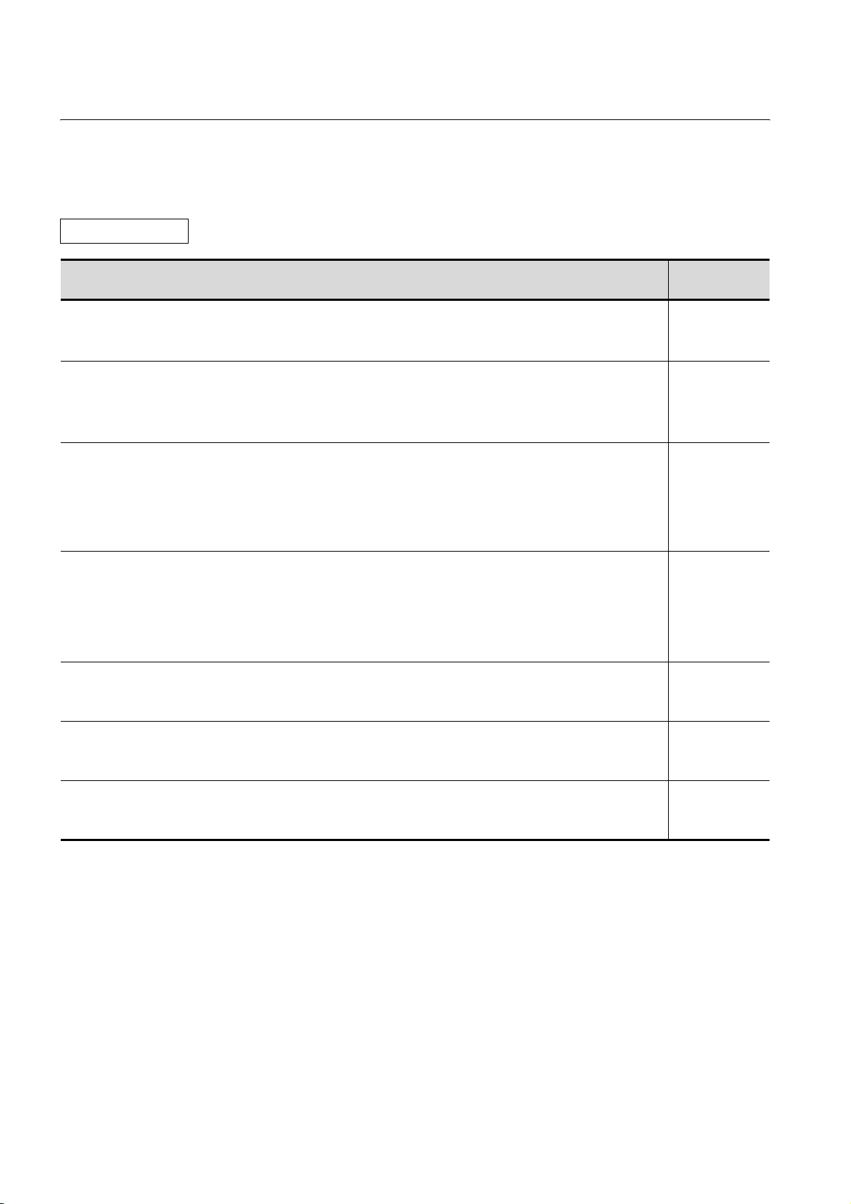
Related Manuals
Manual Name
GT SoftGOT1000 Version2 Operating Manual
Describes
GT Designer2 Version2 Basic Operation/Data Transfer Manual (For GOT1000 Series)
the screen configuration, functions and using method of GT SoftGOT1000.
(Sold separately)
Describes methods of the GT Designer2 installation operation, basic operation for drawing and transmitting data to
GOT1000 series.
(Sold separately)
GT Designer2 Version2 Screen Design Manual (For GOT1000 Series) 1/3
GT Designer2 Version2 Screen Design Manual (For GOT1000 Series) 2/3
GT Designer2 Version2 Screen Design Manual (For GOT1000 Series) 3/3
Describes specifications and settings of the object functions used in GOT1000 series.
(Sold separately)
GOT1000 Series Connection Manual (1/3)
GOT1000 Series Connection Manual (2/3)
GOT1000 Series Connection Manual (3/3)
Describes system configurations of the connection method applicable to GOT1000 series and cable creation
method.
(Sold separately)
GOT1000 Series Extended/Option Functions Manual
Describes extended functions and option functions applicable to GOT series.
(Sold separately)
GOT1000 Series Gateway Functions Manual
Describes specifications, system configurations and setting method of the gateway function.
(Sold separately)
GOT1000 Series MES Interface Function Manual
Describes the specifications, system configurations, and setting method of the MES interface function.
(Sold separately)
*1 The manual in PDF-format is included in the GT Works2 and GT Designer2 products.
Manual Number
(Model Code)
SH-080602ENG
(1D7M48)
SH-080529ENG
(1D7M24)
*1
SH-080530ENG
(1D7M25)
*1
SH-080532ENG
(1D7M26)
*1
SH-080544ENG
(1D7M32)
*1
SH-080545ENG
(1D7M33)
*1
SH-080654ENG
(1D7M63)
*1
A - 20
Page 23
ABBREVIATIONS AND GENERIC TERMS
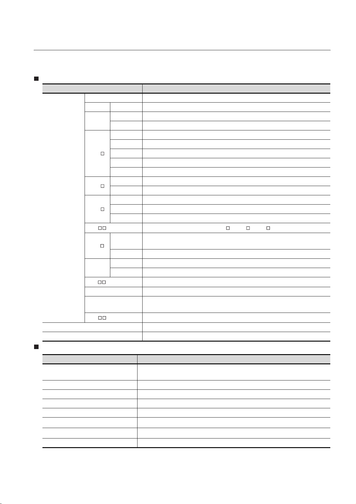
Abbreviations and generic terms used in this manual are as follows:
GOT
Abbreviations and generic terms Description
GT SoftGOT1000 Abbreviation of GT SoftGOT1000
GT1595 GT1595-X Abbreviation of GT1595-XTBA, GT1595-XTBD
GT1585
GT1 57
GT1 56
GOT1000 Series
GOT900 Series Abbreviation of GOT-A900 series, GOT-F900 series
GOT800 Series Abbreviation of GOT-800 series
GT1 55
GT15 , GT15 Abbreviation of GT1595, GT1585, GT157 , GT156 , GT155
GT11 5
Handy
GOT
GT11 , GT 11
GT1030 Abbreviation of GT1030-LBD, GT1030-LBD2, GT1030-LBDW, GT1030-LBDW2
GT1020
GT1 0 , GT10
GT1585V-S Abbreviation of GT1585V-STBA
GT1585-S Abbreviation of GT1585-STBA, GT1585-STBD
GT1575V-S Abbreviation of GT1575V-STBA
GT1575-S Abbreviation of GT1575-STBA, GT1575-STBD
GT1575-V Abbreviation of GT1575-VTBA, GT1575-VTBD
GT1575-VN Abbreviation of GT1575-VNBA, GT1575-VNBD
GT1572-VN Abbreviation of GT1572-VNBA, GT1572-VNBD
GT1565-V Abbreviation of GT1565-VTBA, GT1565-VTBD
GT1562-VN Abbreviation of GT1562-VNBA, GT1562-VNBD
GT1555-V Abbreviation of GT1555-VTBD
GT1555-Q Abbreviation of GT1555-QTBD, GT1555-QSBD
GT1550-Q Abbreviation of GT1550-QLBD
GT11 55-Q
GT1150-Q Abbreviation of GT1150-QLBDQ, GT1150-QLBDA, GT1150-QLBD
GT1155HS-Q Abbreviation of GT1155HS-QSBD
GT1150HS-Q Abbreviation of GT1150HS-QLBD
Abbreviation of GT1155-QTBDQ, GT1155-QSBDQ, GT1155-QTBDA, GT1155-QSBDA,
GT11 55-Q SBD
Abbreviation of GT1155-Q, GT1150-Q, GT11 Handy GOT
Abbreviation of GT1020-LBD, GT1020-LBD2, GT1020-LBL, GT1020-LBDW,
GT1020-LBDW2, GT1020-LBLW
Abbreviation of GT1030, GT1020
Communication unit
Abbreviations and generic terms Description
Bus connection unit
Serial communication unit GT15-RS2-9P,GT15-RS4-9S,GT15-RS4-TE
RS-422 conversion unit GT15-RS2T4-9P,GT15-RS2T4-25P
Ethernet communication unit GT15-J71E71-100
MELSECNET/H communication unit GT15-J71LP23-25,GT15-J71BR13
MELSECNET/10 communication unit
CC-Link communication unit
Interface converter unit GT15-75IF900
*1 A9GT-QJ71LP23 + GT15-75IF900 set
*2 A9GT-QJ71BR13 + GT15-75IF900 set
*3 A8GT-J61BT13 + GT15-75IF900 set
GT15-QBUS,GT15-QBUS2,GT15-ABUS,GT15-ABUS2,
GT15-75QBUSL,GT15-75QBUS2L,GT15-75ABUSL,GT15-75ABUS2L
GT15-75J71LP23-Z*1,GT15-75J71BR13-Z
GT15-J61BT13,GT15-75J61BT13-Z
*3
*2
A - 21
Page 24
Option unit
Abbreviations and generic terms Description
Printer unit GT15-PRN
Video input unit GT15V-75V4
Video/RGB unit
CF card unit GT15-CFCD
CF card extension unit
External I/O unit GT15-DIO
Sound output unit GT15-SOUT
RGB input unit GT15V-75R1
Video/RGB input unit GT15V-75V4R1
RGB output unit GT15V-75ROUT
*1
GT15-CFEX-C08SET
*1 GT15-CFEX + GT15-CFEXIF + GT15-C08CF set.
Option
Abbreviations and generic terms Description
Memory card CF card
Memory card adaptor GT05-MEM-ADPC
Option function board GT15-FNB, GT15-QFNB,GT15-QFNB16M, GT15-QFNB32M, GT15-QFNB48M, GT11-50FNB
Battery GT15-BAT, GT11-50BAT
Protective Sheet
USB environmental protection cover GT15-UCOV, GT11-50UCOV
Stand
Attachment GT15-60ATT-97, GT15-60ATT-96
Backlight
Multi-color display board GT15-XHNB, GT15-VHNB
Connector conversion box GT11H-CNB-37S
Emergency stop sw guard cover GT11H-50ESCOV
GT05-MEM-16MC, GT05-MEM-32MC, GT05-MEM-64MC,
GT05-MEM-128MC, GT05-MEM-256MC
GT15-90PSCB, GT15-90PSGB,GT15-90PSCW,GT15-90PSGW,
GT15-80PSCB, GT15-80PSGB,GT15-80PSCW,GT15-80PSGW,
GT15-70PSCB, GT15-70PSGB, GT15-70PSCW, GT15-70PSGW,
GT15-60PSCB, GT15-60PSGB, GT15-60PSCW, GT15-60PSGW,
GT15-50PSCB, GT15-50PSGB, GT15-50PSCW, GT15-50PSGW,
GT11-50PSCB, GT11-50PSGB, GT11-50PSCW, GT11-50PSGW,
GT11H-50PSC,
GT10-30PSCB, GT10-30PSGB, GT10-30PSCW, GT10-30PSGW,
GT10-20PSCB, GT10-20PSGB, GT10-20PSCW, GT10-20PSGW
GT15-90STAND, GT15-80STAND, GT15-70STAND, A9GT-50STAND,
GT05-50STAND
GT15-90XLTT, GT15-80SLTT, GT15-70SLTT, GT15-70VLTT,GT15-70VLTN,GT15-60VLTT,
GT15-60VLTN
Software
Abbreviations and generic terms Description
GT W orks 2 Ve rsion
GT Designer2 Version
GT Designer2
GT Converter2
GT S i mula t or2
GT SoftGOT1000
GT SoftGOT2
GX Developer
GX Simulator
A - 22
SW D5C-GTWK2-E,SW D5C-GTWK2-EV
SW D5C-GTD2-E,SW D5C-GTD2-EV
Abbreviation of screen drawing software GT Designer2 for GOT1000/GOT900 series
Abbreviation of data conversion software GT Converter2 for GOT1000/GOT900 series
Abbreviation of screen simulator GT Simulator 2 for GOT1000 / GOT900 series
Abbreviation of monitoring software GT SoftGOT1000
Abbreviation of monitoring software GT SoftGOT2
Abbreviation of SW D5C-GPPW-E(-EV)/SW D5F-GPPW-E type software package
Abbreviation of SW D5C-LLT-E(-EV) type ladder logic test tool function software packages
(SW5D5C-LLT (-EV) or later versions)
Page 25
Abbreviations and generic terms Description
Document Converter Abbreviation of document data conversion software Document Converter for GOT1000 series
PX Developer
Abbreviation of SW D5C-FBDQ-E type FBD software package for process control
License key (for GT SoftGOT1000)
Abbreviations and generic terms Description
License GT15-SGTKEY-U, GT15-SGTKEY-P
License key (for GT SoftGOT2)
Abbreviations and generic terms Description
License key A9GTSOFT-LKEY-P (For DOS/V PC)
License key FD SW5D5F-SGLKEY-J (For PC CPU module)
Others
Abbreviations and generic terms Description
Omron PLC Abbreviation of PLC manufactured by OMRON Corporation
KEYENCE PLC Abbreviation of PLC manufactured by KEYENCE
Sharp PLC Abbreviation of PLC manufactured by SHARP Corporation
JTEKT PLC Abbreviation of PLC manufactured by JTEKT Corporation
Toshiba PLC Abbreviation of PLC manufactured by TOSHIBA CORPORATION
HITACHI IES PLC Abbreviation of PLC manufactured by Hitachi Industrial Equipment Systems Co., Ltd.
HITACHI PLC Abbreviation of PLC manufactured by Hitachi, Ltd.
FUJI FA PLC Abbreviation of PLC manufactured by Fuji Electric FA Components & Systems Co., Ltd.
Matsushita PLC Abbreviation of PLC manufactured by Matsushita Electric Works, Ltd
Yaskawa PLC Abbreviation of PLC manufactured by YASKAWA Electric Corporation
Yokogawa PLC Abbreviation of PLC manufactured by Yokogawa Electric Corporation
Allen-Bradley PLC Abbreviation of PLC manufactured by Allen-Bradley
SIEMENS PLC Abbreviation of PLC manufactured by SIEMENS
OMRON temperature
controller
SHINKO indicating
controller
CHINO controller Abbreviation of temperature controller manufactured by CHINO CORPORATION
Temperature
controller
PC CPU module Abbreviation of PC CPU Unit manufactured by CONTEC CO., LTD
GOT (server) Abbreviation of GOTs that use the server function
GOT (client) Abbreviation of GOTs that use the client function
FUJI SYS temperature
controller
YAMATAKE temperature
controller
YOKOGAWA temperature
controller
RKC temperature
controller
Abbreviation of temperature controller manufactured by OMRON
Abbreviation of temperature controller manufactured by Shinko Technos Co., Ltd.
Abbreviation of temperature controller manufactured by Fuji Electric Systems Co., Ltd.
Abbreviation of temperature controller manufactured by YAMATAKE
Abbreviation of temperature controller manufactured by Yokogawa Electric Corporation
Abbreviation of temperature controller manufactured by RKC
Windows font
Intelligent function module
Abbreviation of TrueType font and OpenType font available for Windows
(Differs from the True Type fonts settable with GT Designer2)
Indicates the modules other than the PLC CPU, power supply module and I/O module that are
mounted to the base unit.
A - 23
Page 26
HOW TO READ THIS MANUAL
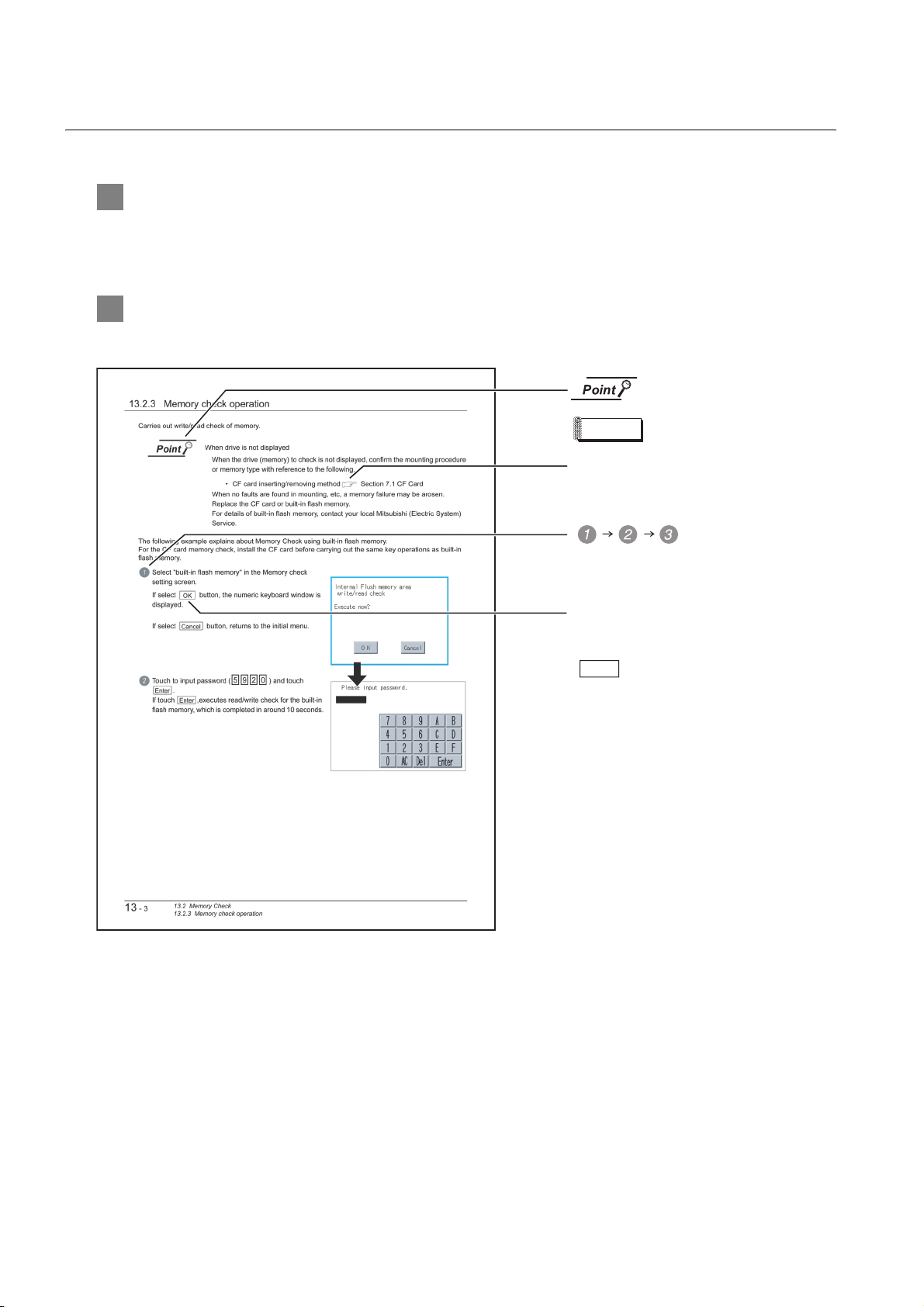
1 Functions
This manual describes functions available for the GT Designer2 Version2.58L.
For the added functions by the product version upgrade, refer to the list of functions added by GT
Desiger2 version upgrade in Appendices.
2 Symbols
Following symbols are used in this manual.
Refers to the information
required.
Remark
Indicates the items in which the detailed
explanation is described (manual, chapter,
section, item of the manual).
Indicates the operation steps.
Refers to the supplementary
explanations for reference.
. . . .
Menu and items are differentiated with
parentheses.
[ ]
: refers to the menu of GOT utility.
: refers to the button in the dialog
box of GOT utility.
* The above is different from the actual page, as it is provided for explanation only.
A - 24
Page 27
PACKIN G LIST
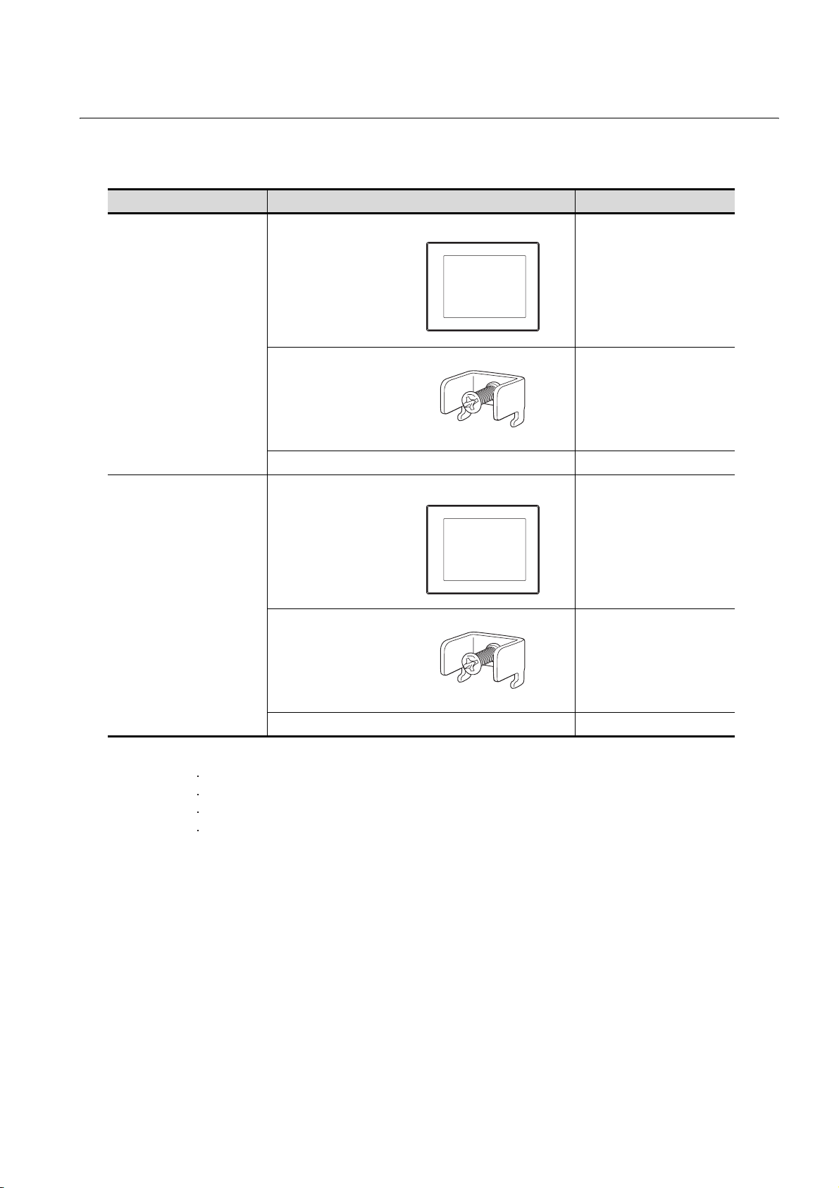
After unpacking, confirm that the following parts are included.
Model Description Quantity
GOT 1
GT1595-X
Installation fitting 8
GT15 General Description 1
GT1585V-S,
GT1585-S,
GT1575V-S,
GT1575-S,
GT1575-V,
GT1575-VN,
GT1572-VN,
GT1565-V,
GT1562-VN,
GT1555-V,
GT1555-Q,
GT1550-Q
GOT 1
Installation fitting 4
GT15 General Description 1
The following products are included a spare for the plastic fixing screw of the GOT.
GT1585-S: Hardware Version B or earlier (Apr.,2005)
GT1575-S: Hardware Version B or earlier (Apr.,2005)
GT1575-V: Hardware Version D or earlier (Apr.,2005)
GT1565-V: Hardware Version D or earlier (Apr.,2005)
A - 25
Page 28
1. OVERVIEW
1 About GOT
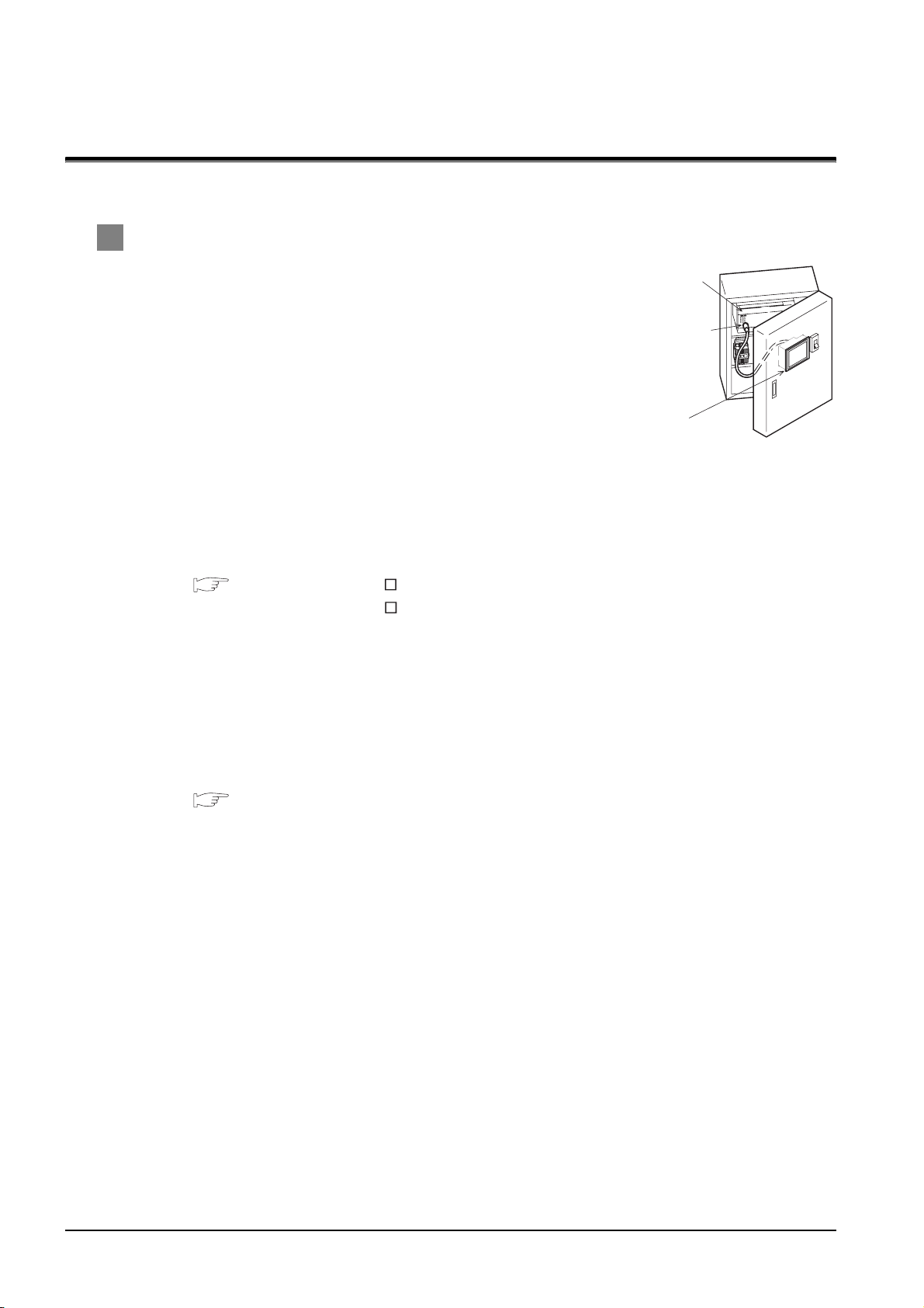
GOT is installed on the panel surface of control panel or operating
panel and connects to the PLC in the control panel. GOT carries out
switch operation, lamp display, data display, and message display etc.
For display screen, two kinds of display screens, user-created screen
and utility screen are available.
(1) User-created Screen
User screen is a screen drawn by GT Designer2.
The objects of "Touch switch", "Lamp display", "Comment
display", and "Numeric display" can be laid out arbitrarily to be displayed.
Moreover, the multiple screens created by GT Designer2 can be overlapped and switched to be
displayed.
For details, refer to the following.
GT Designer2 Version Basic Operation/Data Transfer Manual
GT Designer2 Version Screen Design Manual
PLC
Connector for
program
GOT
(2) Utility Screen
Utility screen is a screen prepared beforehand for GOT.
Installing BootOS or standard OS in the GOT from GT Designer2 enables utility screen displaying.
The utility screen has menus as [Brightness/contrast adjustment screen] and [GOT memory check
screen] etc.
For details, refer to the following.
Chapter 9 to Chapter 17
1 - 1
Page 29
2 About Manual
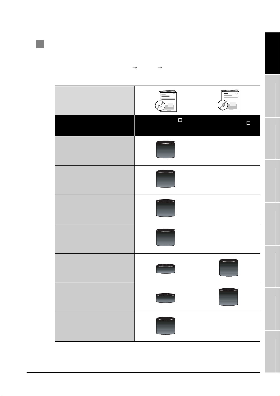
The following manuals related to GOT1000 series are available. Refer to each manual in accordance
with the intended use.
1
(1) Installation of the software programs Drawing Data transfer
For operations from creating project data to transferring data to GOT, refer to the following
manuals.
Purpose
Installing product on PC
Creating projects
GT Designer2 Version Basic
Operation/Data Transfer
*1
Manual
Detailed
Detailed
GT Designer2 Version
Screen Design Manual
OVERVIEW
2
SYSTEM
CONFIGURATION
3
*1
SPECIFICATIONS
4
PART NAME AND
SETTINGS
Creating screens
Drawing figures
Making Common Settings
Placing/Setting objects
Transferring data to GOT
Detailed
Detailed
Overview
Overview
Detailed
Detailed
Detailed
EMC AND LOW
5
VOLTAGE
6
INSTALLATION
7
WIRING
8
DIRECTIVE
*1 Stored in the GT Works2/GT Designer2 in PDF format.
OPTION
1 - 2
Page 30
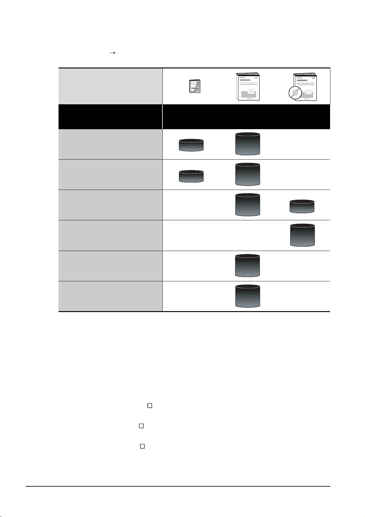
(2) Installing a GOT Connecting to a controller
For the operations from installing a GOT to communicating with a controller, refer to the following manuals
(Included)
.
Purpose
Confirming part names and
specifications of the GOT
Confirming the GOT installation method
Confirming the mounting method for
extension units or option devices
Confirming the PLC connection method
Confirming the utility operation method
GT15 General
Description GT11
General Description
Overview
Overview
GT15 User's Manual
GT11 User's Manual
Detailed
Detailed
Detailed
Detailed
GOT1000 Series
Connection Manual
Overview
Detailed
*1
Confirming error codes (system alarm)
displayed on the GOT
*1 Stored in the GT Works2/GT Designer2 in PDF format.
Detailed
(3) Other manuals
The following manuals are also available.
The following manuals are stored in the GT Works2/GT Designer2 in PDF format.
(a) GOT1000 Series Extended/Option Functions Manual
Describes functions for more efficient debugging as the ladder monitor function, system
monitor function and A list edit function.
(b) GOT1000 Series Gateway Functions Manual
Describes how to use the gateway function.
(c) GT SoftGOT1000 Version Operating Manual
Describes how to use the GT SoftGOT1000 and various functions.
(d) GT Simulator2 Version Operating Manual
Describes how to simulate the created project data with the GT Simulator2.
(e) GT Converter2 Version Operating Manual
Describes how to use the GT Converter2.
(f) GOT1000 Series MES Interface Function Manual
Describes how to use the GT MES Interface Function.
1 - 3
Page 31
1.1 Features
(1) Improved monitoring performance and connectivity to FA devices
• Using of TFT color liquid crystal display (high intensity, wide angle view and high definition type)
provides clear full-color display and displays small characters clearly. (Displays digital images of
BMP and other formats in 65536 colors.)
• Provides multi-language display function based on Unicode2.1 True Type font and high-speed
drawing of beautiful text.
• High speed monitoring through high speed communication at maximum of 115.2kbps.
• High speed display and high speed touch switch response.
*1
1
OVERVIEW
2
(2) More efficient GOT operations including screen design, startup, adjustment, management and
maintenance works
• 9MB user memory is included as standard. (Memory capacity can be expanded up to 57MB by
increasing the option memory)
• CF card interface is included as standard.
• Font installation is available to increase the system fonts.
• Combined use of 4 types of alarms (system alarm, user alarm, alarm history, alarm popup
display) realizes more efficient alarm notification.
• Maintenance timing report function is available that measures the backlight energization time
and notifies of maintenance time.
• The USB connector is positioned on the GOT front. This enables the system startup to be
performed more efficiently using FA device startup tool, and eliminates the necessity of indirect
works (opening and closing the control panel, cable replacement, cable rewiring) in order to
improve the working efficiency.
• The blown backlight bulb can be confirmed even during screen saving, with the blinked POWER
LED at backlight shutoff detection.
(3) Enhanced support of FA device setup tools
• Transferring and monitoring sequence programs with the personal computer connected to the
GOT can be executed when connecting to a PLC CPU with the direct CPU connection or bus
connection. (FA transparent function)
*1
EMC AND LOW
SYSTEM
CONFIGURATION
3
SPECIFICATIONS
4
PART NAME AND
SETTINGS
5
VOLTAGE
DIRECTIVE
*1 The specifications differ depending on the GOT to be used.
For the specifications, refer to the following.
3.2 Performance Specifications
6
INSTALLATION
7
WIRING
8
OPTION
1.1 Features
1 - 4
Page 32
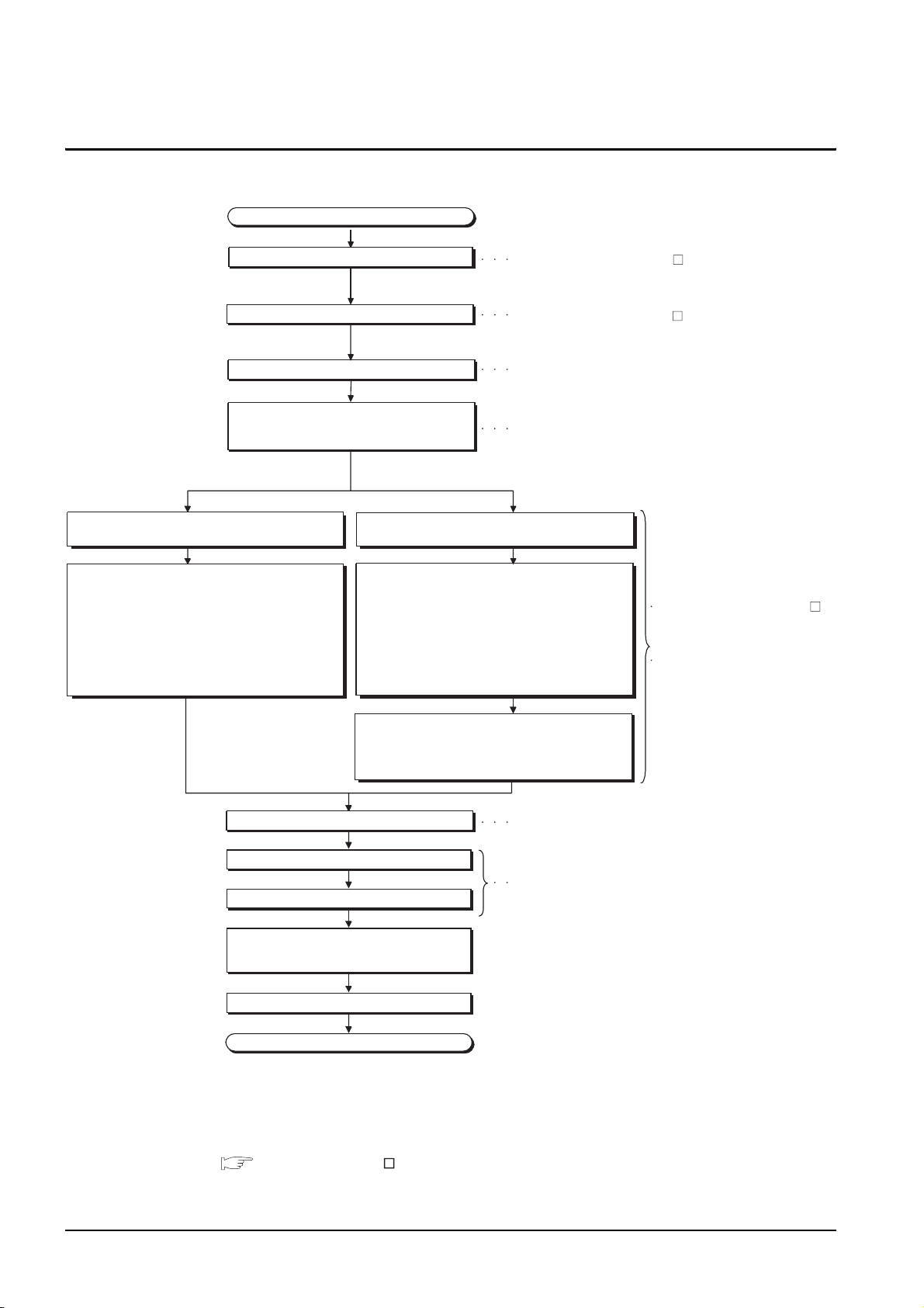
1.2 Rough Pre-operation Procedure
The outline procedure before operating GOT is shown.
Start
Install GT Designer2 in the PC.
Create project data.
Wire for the GOT power supply.
Mount the option function board or multi-color
display board.
(As necessary)
When transfer data via a cable. When transfer data via the memory card.
Connect GOT and PC with a USB cable or
RS-232 cable.
Install and download the OS program, project data
installed in the PC to the GOT.
1) Install standard monitor OS, communication driver,
extended function OS, option OS to the GOT.
After installation is completed, the GOT
automatically restarts.
2) Download the project data created by the PC.
*1
Insert the memory card in the PC.
Write the OS, program, project data installed in the PC
in the memory card.
1) Write the standard monitor OS, communication
driver, extended function OS, option OS, project
data in the memory card.
Refer to GT Designer2 Version
Basic Operation/Data Transfer Manual
Refer to GT Designer2 Version Screen Design Manual
Refer to Chapter 7 WIRING
Refer to Chapter 8 Option.
Refer to GT Designer2 Version
Basic Operation/Data Transfer
Manual
Refer to Chapter 18 INSTALLATION
OF COREOS, BOOTOS AND
STANDARD OS in this manual for
the operations of GOT.
Install the memory card to the GOT to install and
download the standard monitor OS, communication
driver, extended function OS, option OS, project data
to the GOT.
Mount units to GOT.
Check the Communication settings.
Connect the GOT and controller with a cable.
Turn on the power supply of GOT and
the system of the connection destination.
Start the monitor.
End
Refer to Chapter 8 OPTION.
Refer to GOT1000 Series Connection Manual.
* 1 Project data can be also downloaded/uploaded via Ethernet.
For download/upload of project data via Ethernet, BootOS and standard monitor OS should be installed in the
GOT in advance so that the GOT and PC can communicate with each other via Ethernet by setting
Communication Settings.
Refer to the following manual for details.
GT Designer2 Version Basic Operation/Data Transfer Manual (Chapter 8 TRANSFERRING DATA)
1 - 5
1.2 Rough Pre-operation Procedure
Page 33
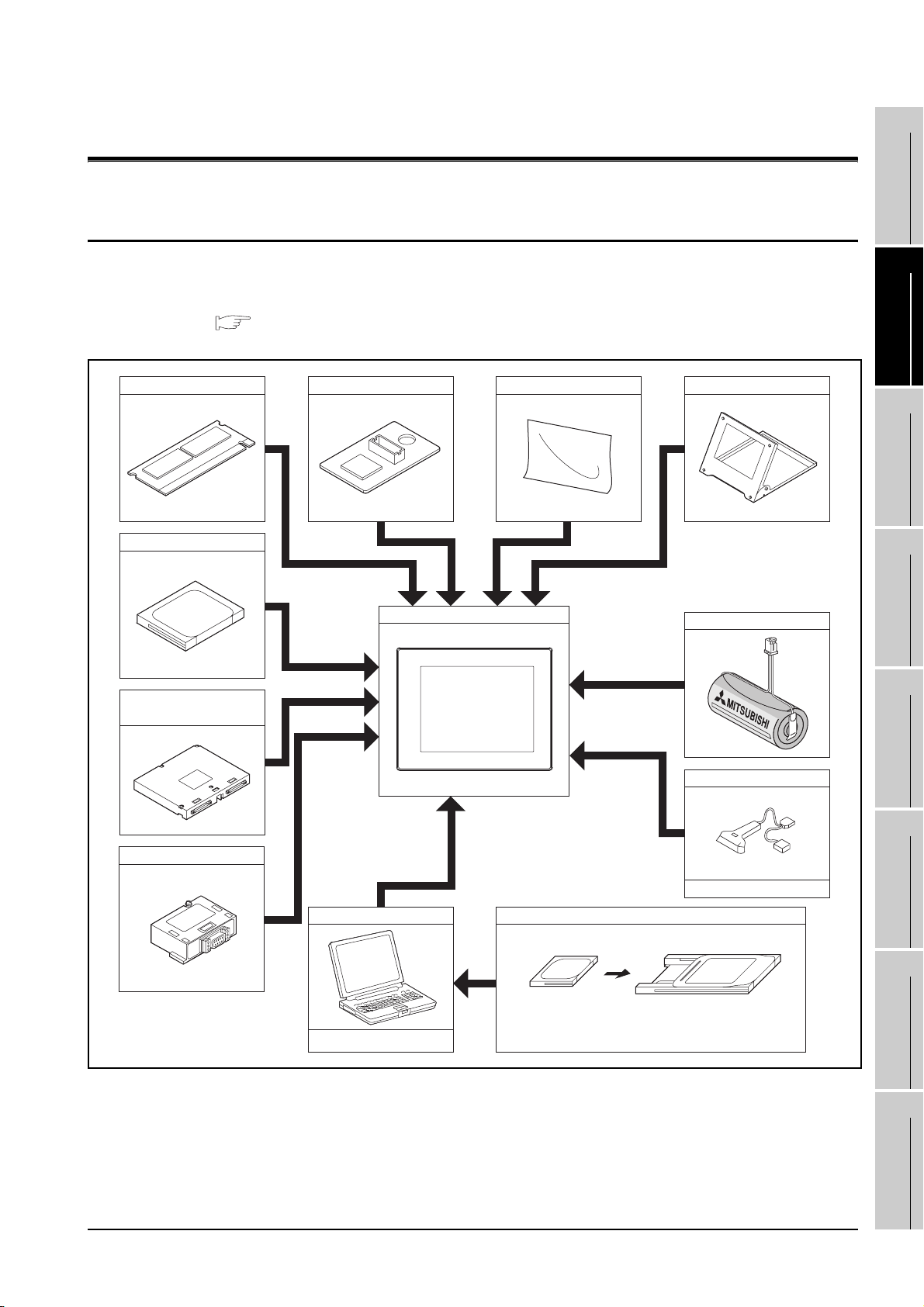
2. SYSTEM CONFIGURATION
1
2.1 Overall Configuration
The overall configuration of GOT is as follows.
For the connection methods applicable to GOT1000 series and cable, refer to the following.
GOT1000 Series Connection Manual
Option function board
CF card
Multi-color display board
GOT
Protective sheet Stand
Battery
OVERVIEW
2
SYSTEM
CONFIGURATION
3
SPECIFICATIONS
4
PART NAME AND
SETTINGS
Extension unit
RS-422 conversion unit
Personal computer
Commercially available
Bar code reader
Commercially available
Memory card
CF card Memory card adaptor
EMC AND LOW
5
VOLTAGE
6
INSTALLATION
7
WIRING
8
DIRECTIVE
2.1 Overall Configuration
OPTION
2 - 1
Page 34
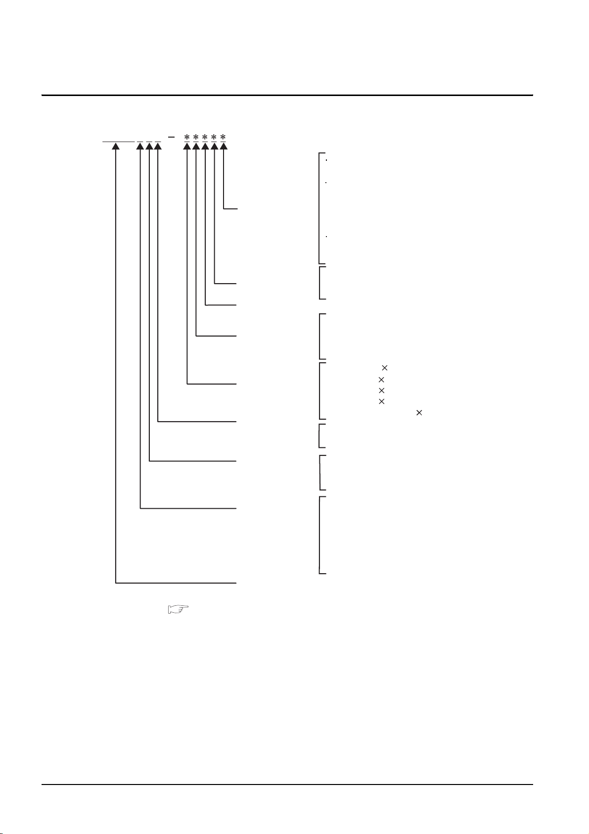
2.2 Component List
(1) Explanation of the GOT model name
GT1575V
Communication
interface
Power type
Panel color type
Display device type
Resolution
Video/RGB
GT15
(None) : RS-232 interface
GT11
Q : Bus interface for Q series CPU
A : Bus interface for A series CPU
(None) : RS-232 interface
RS-422 interface
GT10
2 : RS-232 interface
(None) : RS-422 interface
A : 100 to 240VAC
D : 24VDC
L : 5VDC
B : Black
T : TFT color (High intensity, Wide angle view)
N : TFT color
S : STN color
L : STN monochrome
X : 1024 768 (XGA)
S : 800 600 (SVGA)
V : 640 480 (VGA)
Q : 320 240 (QVGA)
(None) : Less than 320 240
V : Video/RGB compliant
(None) : -
Model type
Screen size type
GOT 1000 series GT15/GT11
*1 For GOTs that can display 65536 colors, refer to the following.
3.2 Performance Specifications
*2 Not 16 gray scale for GT10
5 : 65536/4096/256 colors
2 : 16 colors
0 : Monochrome (White/Black), 16 gray scale
9 : 15"
8 : 12.1"
7 : 10.4"
6 : 8.4"
5 : 5.7"
3 : 4"
2 : 3.7"
*1
*2
2 - 2
2.2 Component List
Page 35
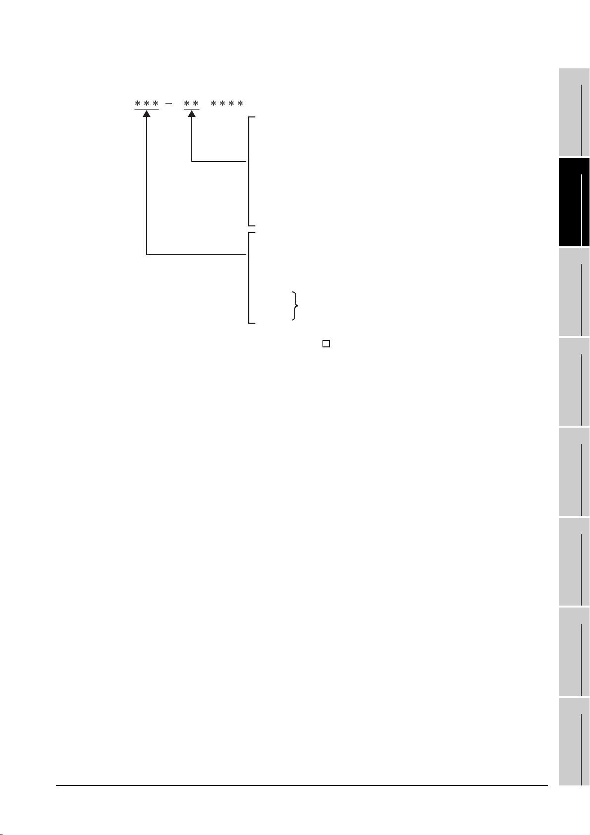
(2) Explanation of the option model name
GT
(None) : Common for all types
90 : Dedicated for 15"
80 : Dedicated for 12.1"
75 : Common for 15", 12.1",10.4", 8.4",
(Partially common for 5.7 ")
70 : Dedicated for 10.4"
60 : Dedicated for 8.4"
50 : Dedicated for 5.7"
30 : 4"
20 : 3.7"
15V : Dedicated for video/RGB compliant model
15 : Dedicated for GT15
11 : Dedicated for GT11,
(Partially common for GT15/GT11)
10 : Dedicated for GT10
09 :
05 :
01 :
*1 The bus connection unit (GT15-75QBUSL, GT15-75QBU2L, GT15-75ABUSL,
GT15-75ABUS2L), can also be used with GT155 .
*2 The USB environmental protection cover (GT11-50UCOV) can be used for
both the GT15 and GT11.
Common for GT15/GT11
1
OVERVIEW
*1
2
SYSTEM
CONFIGURATION
3
*2
SPECIFICATIONS
4
EMC AND LOW
PART NAME AND
SETTINGS
5
VOLTAGE
6
INSTALLATION
7
WIRING
DIRECTIVE
2.2 Component List
8
OPTION
2 - 3
Page 36
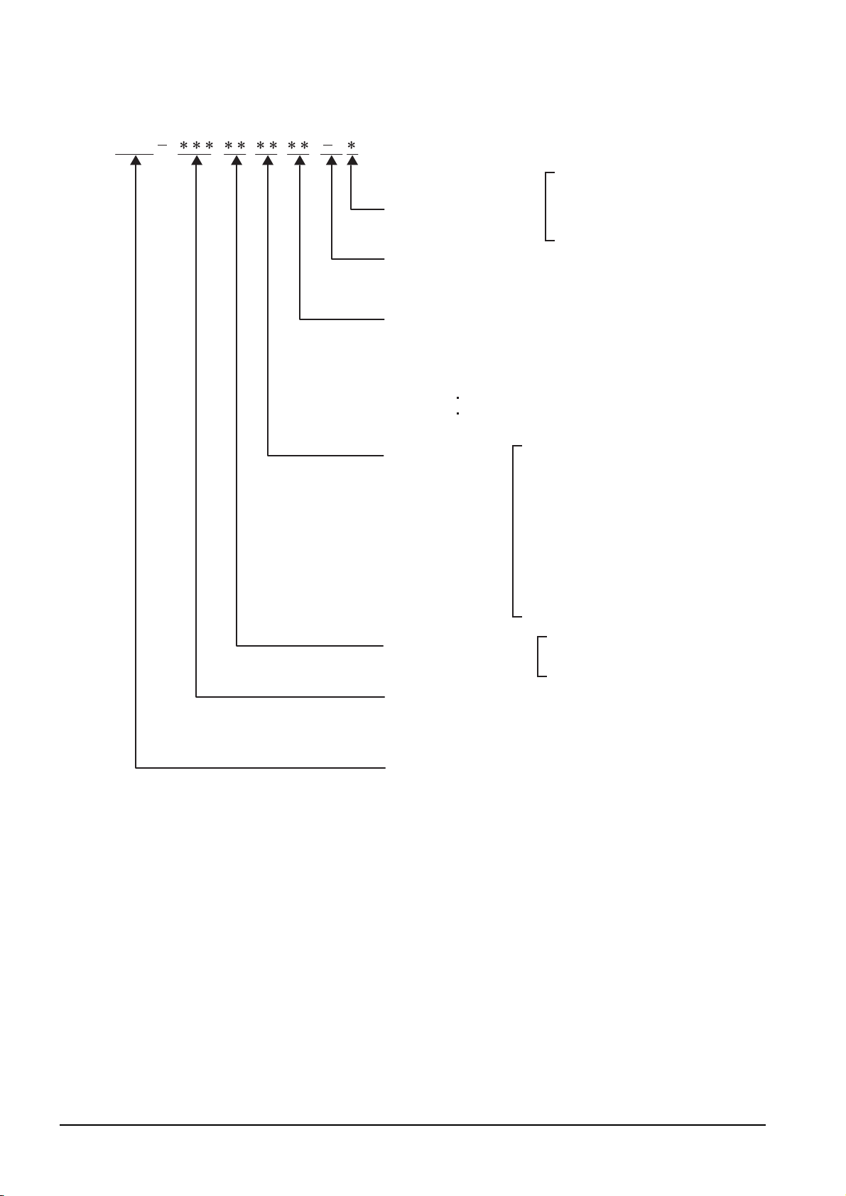
(3) Third party PLC connection cable
GT09 C
n
Connector pin type of the
connection target
(For third party PLC side)
Number of connector pins
(Indicates the number of terminals for solderless or
preparatory-soldered terminals.)
Cable distinction numbers for one manufacturer's
products
(Two-digit sequence number: 01, 02, ...)
* When cable distinction is needed for one manufacture's
products
Example) Wirings are different for each PLC type.
Connecting targets are different, such as servo,
inverter, temperature controller.
Cable classification
P: Plug (male)
S: Socket (female)
T: Solderless terminal
C: Preparatory soldering
01: For OMRON PLC
02: For YASKAWA PLC
03: For YOKOGAWA PLC
04: For HITACHI PLC
05: For TOSHIBA PLC
06: For SHARP PLC
07: For Allen-Bradley PLC
08: For SIEMENS PLC
09: For MATSUSHITA PLC
11: For KEYENCE PLC
12: JTEKT PLC
Application classification
(For GOT1000 side)
Length classification
* Indicated in 10cm unit.
Example) 3m : 30
30m: 300
Third party PLC connection cable
(Commonly used for GT15 and GT11)
R2: For RS232 communication
R4: For RS422 communication
2 - 4
2.2 Component List
Page 37
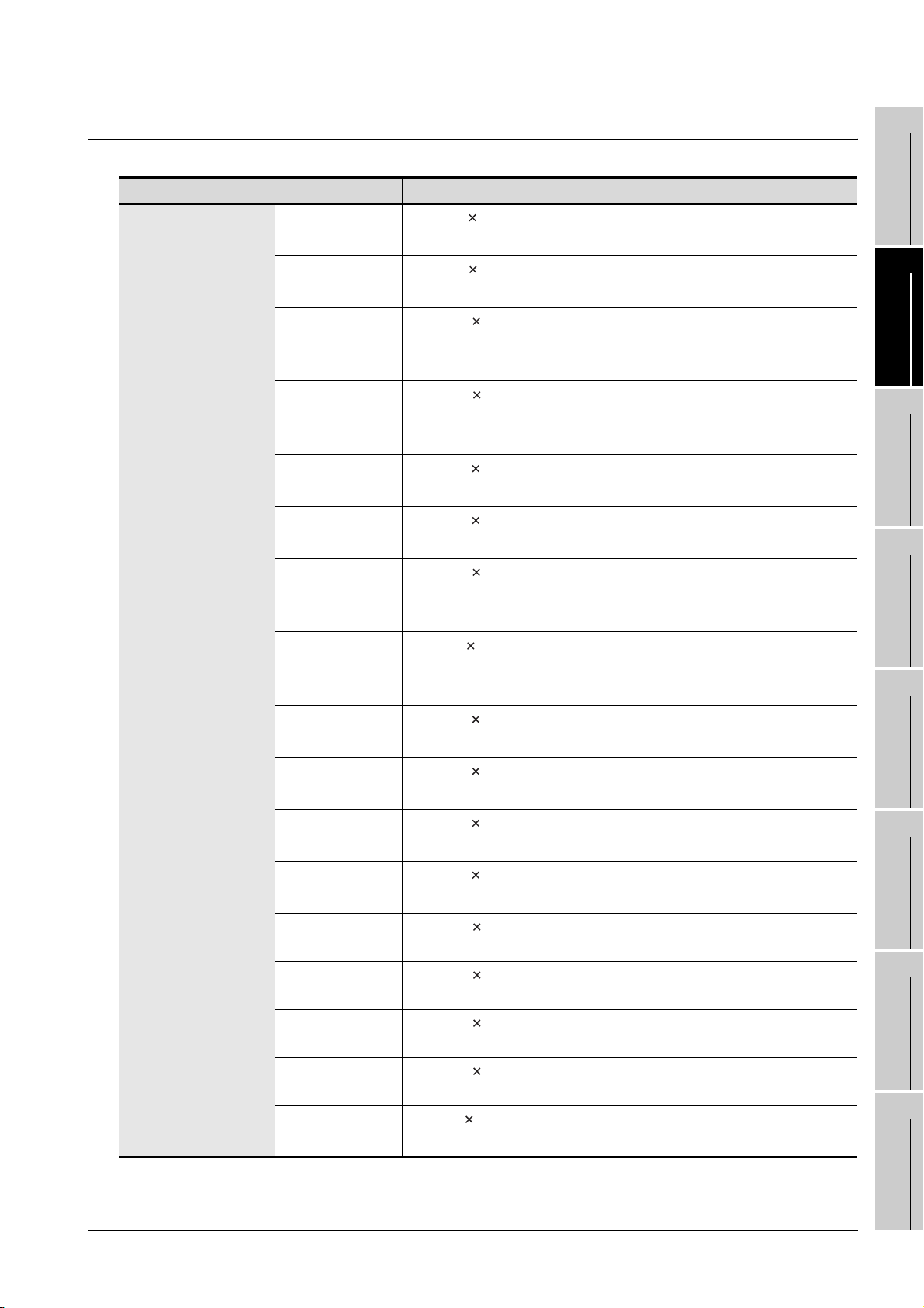
2.2.1 GOT
Product name Model name Specifications
GT1595-XTBA
GT1595-XTBD
GT1585V-STBA
GT1585V-STBD
GT1585-STBA
GT1585-STBD
GT1575V-STBA
15" (1024 768 dots), TFT color liquid crystal, (high intensity, wide angle
view), 65536 colors*1, 100 to 240VAC, Memory size 9MB
15" (1024 768 dots), TFT color liquid crystal (high intensity, wide angle
view), 65536 colors
12.1" (800 600 dots), TFT color liquid crystal (high intensity, wide angle
view), 65536 colors
size 9MB
12.1" (800 600 dots), TFT color liquid crystal display (high intensity,
wide angle view), 65536 colors
size 9MB
12.1" (800 600 dots), TFT color liquid crystal, (high intensity, wide angle
view), 65536 colors
12.1" (800 600 dots), TFT color liquid crystal, (high intensity, wide angle
view), 65536 colors
10.4" (800 600 dots), TFT color liquid crystal (high intensity, wide angle
view), 65536 colors
size 9MB
*1
, 24VDC, memory size 9MB
*1
, video/RGB compliant, 100 to 240VAC, memory
*1
, video/RGB compliant, 24VDC, memory
*1
, 100 to 240VAC, Memory size 9MB
*1
, 24VDC, Memory size 9MB
*1
, video/RGB compliant, 100 to 240VAC, memory
1
2
SYSTEM
3
4
OVERVIEW
CONFIGURATION
SPECIFICATIONS
GOT
GT1575V-STBD
GT1575-STBA
GT1575-STBD
GT1575-VTBA
GT1575-VTBD
GT1575-VNBA
GT1575-VNBD
GT1572-VNBA
GT1572-VNBD
GT1565-VTBA
10.4 (800 600 dots), TFT color liquid crystal display (high intensity, wide
angle view), 65536 colors
9MB
10.4" (800 600 dots), TFT color liquid crystal, (high intensity, wide angle
view), 65536 colors
10.4" (800 600 dots), TFT color liquid crystal, (high intensity, wide angle
view), 65536 colors
10.4" (640 480 dots), TFT color liquid crystal, (high intensity, wide angle
view), 65536 colors
10.4" (640 480 dots), TFT color liquid crystal, (high intensity, wide angle
view), 65536 colors
10.4" (640 480 dots), TFT color liquid crystal,
256 colors, 100 to 240VAC, Memory size 5MB
10.4" (640 480 dots), TFT color liquid crystal,
256 colors, 24VDC, Memory size 5MB
10.4" (640 480 dots), TFT color liquid crystal,
16 colors, 100 to 240VAC, Memory size 5MB
10.4" (640 480 dots), TFT color liquid crystal,
16 colors, 24VDC, Memory size 5MB
8.4" (640 480 dots), TFT color liquid crystal, (high intensity, wide angle
view), 65536 colors
*1
, video/RGB compliant, 24VDC, memory size
*1
, 100 to 240VAC, Memory size 9MB
*1
, 24VDC, Memory size 9MB
*1
, 100 to 240VAC, Memory size 9MB
*1
, 24VDC, Memory size 9MB
*1
, 100 to 240VAC, Memory size 9MB
EMC AND LOW
PART NAME AND
SETTINGS
5
VOLTAGE
6
INSTALLATION
7
WIRING
8
DIRECTIVE
(Continued to next page)
2.2 Component List
2.2.1 GOT
OPTION
2 - 5
Page 38
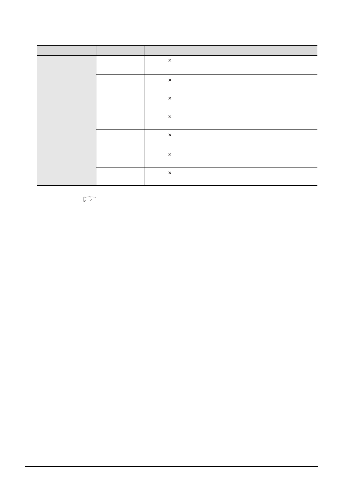
Product name Model name Specifications
GOT
GT1565-VTBD
GT1562-VNBA
GT1562-VNBD
GT1555-VTBD
GT1555-QTBD
GT1555-QSBD
GT1550-QLBD
*1: For GOTs supporting 65536 colors, refer to the following.
3.2 Performance Specifications
8.4" (640 480 dots), TFT color liquid crystal, (high intensity, wide angle
view), 65536 colors
8.4" (640 480 dots), TFT color liquid crystal,
16 colors, 100 to 240VAC, Memory size 5MB
8.4" (640 480 dots), TFT color liquid crystal,
16 colors, 24VDC, Memory size 5MB
5.7" (640 480 dots), TFT color liquid crystal (high intensity, wide angle
view), 65536 colors, 24VDC, memory size 9MB
5.7" (320 240 dots), TFT color liquid crystal (high intensity, wide angle
view), 65536 colors
5.7" (320 240 dots), STN color liquid crystal, 4096 colors, 24VDC,
memory size 9MB
5.7" (320 240 dots), STN monochrome liquid crystal, 16 (Grayscale),
24VDC, memory size 9MB
*1
, 24VDC, Memory size 9MB
*1
, 24VDC, memory size 9MB
2 - 6
2.2 Component List
2.2.1 GOT
Page 39
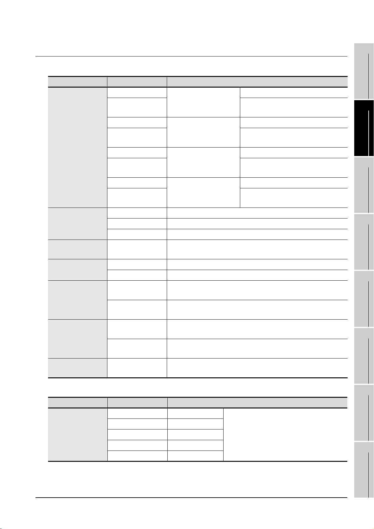
2.2.2 Option
Communication unit (Sold separately)
Product name Model name Description
Bus connection unit
Serial communication
unit
Ethernet
communication unit
GT1 5-QB U
GT15-QBUS2
GT15-ABUS
GT15-ABUS2
GT15-75QBUSL
GT15-75QBUS2L
GT15-75ABUSL
GT15-75ABUS2L
GT15-RS2 For RS-232 interface connection, connector type
GT15-RS4 For RS-422 interface connection, connector type
GT15-RS4-TE For RS-422 interface connection, terminal block type
GT15-J71E71-100 Ethernet (100Base-TX/10Base-T) unit
For QCPU (Q Mode)/Motion
controller CPU (Q Series)
connection (standard model)
For A/QnACPU/Motion
controller
connection (standard model)
For QCPU (Q Mode)/Motion
controller CPU (Q Series)
connection (slim model)
For A/QnACPU/Motion
controller CPU (A Series)
connection (slim model)
CPU
(A Series)
For terminal GOT, 1 Channel
For intermediary and terminal GOTs, 2
channels
For terminal GOT, 1 Channel
For intermediary and terminal GOTs, 2
channels
For terminal GOT, 1 Channel
For intermediary and terminal GOTs, 2
channels
For terminal GOT, 1 Channel
For intermediary and terminal GOTs, 2
channels
1
2
SYSTEM
3
4
OVERVIEW
CONFIGURATION
SPECIFICATIONS
MELSECNET/H
communication unit
MELSECNET/10
communication unit
CC-Link
communication unit
Interface converter
unit
GT15-J71LP23-25 Optical double loop unit
GT15-J71BR13 Coaxial bus unit
GT15-75J71LP23-Z
GT15-75J71BR13-Z
GT15-J61BT13
GT15-75J61BT13-Z
GT15-75IF900 Conversion unit for GOT-A900/GOT800 series communication unit
Optical loop unit
(A9GT-QJ71LP23 + GT15-75IF900 set)
Coaxial bus unit
(A9GT-QJ71BR13 + GT15-75IF900 set)
Intelligent device station unit
CC-LINK Ver. 2 compliant
Intelligent device station unit
(A8GT-J61BT13 + GT15-75IF900 set)
QCPU (Q Mode) bus connection cable (Sold separately)
Product name Model name Description
GT15-QC06B Cable length 0.6m
Q extension cable
GOT-to-GOT
connection cable
GT15-QC12B Cable length 1.2m
GT15-QC30B Cable length 3m
GT15-QC50B Cable length 5m
GT15-QC100B Cable length 10m
For connecting QCPU and GOT
For connecting GOT and GOT
EMC AND LOW
PART NAME AND
SETTINGS
5
VOLTAGE
6
INSTALLATION
7
WIRING
8
DIRECTIVE
(Continued to next page)
2.2 Component List
2.2.2 Option
OPTION
2 - 7
Page 40
Product name Model name Description
Q long distance
connection cable
GOT-to-GOT long
distance connection
cable
GT15-QC150BS Cable length 15m
GT15-QC200BS Cable length 20m
GT15-QC250BS Cable length 25m
GT15-QC300BS Cable length 30m
GT15-QC350BS Cable length 35m
For long distance connection (13.2m or longer)
of QCPU and GOT (A9GT-QCNB is necessary)
For long distance connection of GOT and GOT
QnA/ACPU/Motion controller (A series) bus connection cable (Sold separately)
Product name Model name Description
GT15-A1SC07B Cable length 0.7m
For connecting QnAS/AnSCPU/Motion controller
CPU (A series) and GOT
For connecting QnAS/AnSCPU/motion controller
CPU (A series) and A7GT-CNB
For connecting QnA/ACPU/Motion controller
CPU (A series /Extension base) and GOT
Small-size CPU
extension cable
GOT-to-GOT
connection cable
GT15-A1SC12B Cable length 1.2m
GT15-A1SC30B Cable length 3m
GT15-A1SC50B Cable length 5m For connecting QnAS/AnSCPU and GOT
GT15-A1SC05NB Cable length 0.45m
GT15-A1SC07NB Cable length 0.7m
GT15-A1SC30NB Cable length 3m
GT15-A1SC50NB Cable length 5m For connecting QnAS/AnSCPU and A7GT-CNB
GT15-C12NB Cable length 1.2m
GT15-C30NB Cable length 3m
GT15-C50NB Cable length 5m
GT15-AC06B Cable length 0.6m
Large-size CPU
extension cable
Small-size CPU
long distance
connection cable
GT15-AC12B Cable length 1.2m
GT15-AC30B Cable length 3m
GT15-AC50B Cable length 5m
GT15-A370C12B-S1 Cable length 1.2m
GT15-A370C25B-S1 Cable length 2.5m
GT15-A370C12B Cable length 1.2m
GT15-A370C25B Cable length 2.5m
GT15-C100EXSS-1 Cable length 10.6m
GT15-C200EXSS-1 Cable length 20.6m
GT15-C300EXSS-1 Cable length 30.6m
For connecting QnA/ACPU/Motion controller
CPU (A series /Extension base) and A7GT-CNB
For connecting Motion controller CPU (A series /
Extension base) and GOT
For connecting Motion controller CPU (A series /
Extension base) and A7GT-CNB
For long distance connection of QnAS/AnSCPU/
motion controller CPU (A series) and GOT
For connecting A7GT-CNB and a combined
product of the GT15-EXCNB and GT15-C BS (for
long distance connection)
(Continued to next page)
2 - 8
2.2 Component List
2.2.2 Option
Page 41
Product name Model name Description
GT15-C07BS Cable length 0.7m
GT15-C12BS Cable length 1.2m
GOT-to-GOT long
distance connection
cable
A0J2HCPU
connection cable
Buffer circuit cable GT15-EXCNB Cable length 0.5m
GT15-C30BS Cable length 3m
GT15-C50BS Cable length 5m
GT15-C100BS Cable length 10m
GT15-C200BS Cable length 20m
GT15-C300BS Cable length 30m
GT15-J2C10B Cable length 1m
For connecting GOT and GOT
For connecting A0J2HCPU power supply module
(A0J2-PW) and GOT
Combined with GT15-C BS, can be used as
GT15-C EXSS-1
Connection cables for MITSUBISHI PLCs (Sold separately)
Product name Model name Description
RS-232
cable
QCPU direct
connection cable
FX communication
function extension
board connection
cable,
FX communication
function adapter
connection cable,
data transfer cable
FX communication
function adaptor
connection cable,
data transfer cable
GT01-C30R2-6P Cable length 3m For connecting QCPU and GOT
For connecting FXCPU communication
function extension board (D-sub 9 pins
connector), FXCPU communication function
GT01-C30R2-9S Cable length 3m
GT01-C30R2-25P Cable length 3m
adapter (D-sub 9 pins connector) and GOT
For connecting personal computer (Drawing
software) (D-sub 9 pins: female) and GOT
(D-sub 9 pins: female)
For connecting FXCPU communcation
function adaptor (D-sub 25 pins connector)
and GOT
For connecting personal computer (Drawing
software) (D-sub 25 pins: male) and GOT
(D-sub 9 pins: female)
EMC AND LOW
1
OVERVIEW
2
SYSTEM
CONFIGURATION
3
SPECIFICATIONS
4
PART NAME AND
SETTINGS
5
VOLTAGE
6
DIRECTIVE
Computer link
connection cable
GT09-C30R2-9P Cable length 3 m
GT09-C30R2-25P Cable length 3 m
For connecting computer link module/serial
communication module and GOT
(Continued to next page)
2.2 Component List
2.2.2 Option
2 - 9
INSTALLATION
7
WIRING
8
OPTION
Page 42
Product name Model name Description
GT01-C10R4-8P Cable length 1m
RS-422
cable
FXCPU direct
connection cable,
FX communication
function extension
board connection
cable
QnA/A/FXCPU
direct connection
cable, computer
link connection
cable
Computer link
connection cable
GT01-C30R4-8P Cable length 3m
GT01-C100R4-8P Cable length 10m
GT01-C200R4-8P Cable length 20m
GT01-C300R4-8P Cable length 30m
GT01-C30R4-25P Cable length 3m
GT01-C100R4-25P Cable length 10m
GT01-C200R4-25P Cable length 20m
GT01-C300R4-25P Cable length 30m
GT09-C30R4-6C Cable length 3 m
GT09-C100R4-6C Cable length 10 m
GT09-C200R4-6C Cable length 20 m
For connecting FXCPU (MINI DIN 8 pins
connector) and GOT
For connecting FXCPU communication
function extension board (MINI DIN 8 pins
connector) and GOT
For connecting QnA/ACPU/Motion controller
CPU (A series)/FX (FX
For connecting FA-CNV
For connecting computer link module/serial
communication module and GOT
For connecting computer link module/serial
communication module and GOT
1,FX2,FX2C) and GOT
CBL and GOT
GT09-C300R4-6C Cable length 30 m
Connection cables for OMRON PLCs (Sold separately)
Product
name
RS-232
cable
RS-422
cable
Model name Description
GT09-C30R20101-9P Cable length 3m
GT09-C30R20102-25S Cable length 3m For connecting GOT to OMRON connection cable
GT09-C30R20103-25P Cable length 3m For connecting GOT to OMRON rack type host link unit
GT09-C30R40101-9P Cable length 3m
GT09-C100R40101-9P Cable length 10m
GT09-C200R40101-9P Cable length 20m
GT09-C300R40101-9P Cable length 30m
GT09-C30R40102-9P Cable length 3m
GT09-C100R40102-9P Cable length 10m
GT09-C200R40102-9P Cable length 20m
GT09-C300R40102-9P Cable length 30m
For connecting GOT to OMRON PLC, serial communication
module, communication board, serial communication board
For connecting GOT to OMRON PLC, serial communication
module, serial communication board
For connecting GOT to OMRON rack type host link unit,
communication board
2 - 10
2.2 Component List
2.2.2 Option
Page 43
Connection cables for KEYENCE PLCs (Sold separately)
1
Product
name
RS-232
cable
RS-422
cable
Model name Description
GT09-C30R21101-6P Cable length 3m For connecting GOT to KEYENCE PLC
GT09-C30R21102-9S Cable length 3m For connecting GOT to KEYENCE multi-communication unit
GT09-C30R21103-3T Cable length 3m For connecting GOT to KEYENCE multi-communication unit
GT09-C30R41101-5T Cable length 3m
GT09-C100R41101-5T Cable length 10m
For connecting GOT to KEYENCE multi-communication unit
GT09-C200R41101-5T Cable length 20m
GT09-C300R41101-5T Cable length 30m
Connection cables for SHARP PLCs (Sold separately)
Product
name
RS-232
cable
RS-422
cable
Model name Description
GT09-C30R20601-15P Cable length 3m For connecting GOT to SHARP PLC
GT09-C30R20602-15P Cable length 3m For connecting GOT to SHARP PLC
GT09-C30R40601-15P Cable length 3m
GT09-C100R40601-15P Cable length 10m
GT09-C200R40601-15P Cable length 20m
GT09-C300R40601-15P Cable length 30m
GT09-C30R40602-15P Cable length 3m
GT09-C100R40602-15P Cable length 10m
GT09-C200R40602-15P Cable length 20m
GT09-C300R40602-15P Cable length 30m
GT09-C30R40603-6T Cable length 3m
GT09-C100R40603-6T Cable length 10m
GT09-C200R40603-6T Cable length 20m
GT09-C300R40603-6T Cable length 30m
For connecting GOT to SHARP PLC
For connecting GOT to SHARP PLC
For connecting GOT to SHARP link unit
OVERVIEW
2
SYSTEM
CONFIGURATION
3
SPECIFICATIONS
4
PART NAME AND
SETTINGS
5
Connection cables for JTEKT PLCs (Sold separately)
Product
name
RS-232
cable
RS-422
cable
Model name Description
GT09-C30R21201-25P Cable length 3 m For connecting GOT to JTEKT PLC
GT09-C30R41201-6C Cable length 3 m
GT09-C100R41201-6C Cable length 10 m
GT09-C200R41201-6C Cable length 20 m
GT09-C300R41201-6C Cable length 30 m
For connecting GOT to JTEKT PLC
2.2 Component List
2.2.2 Option
2 - 11
EMC AND LOW
VOLTAGE
6
INSTALLATION
7
WIRING
8
OPTION
DIRECTIVE
Page 44
Connection cables for TOSHIBA PLCs (Sold separately)
Product
name
RS-232
cable
RS-422
cable
Model name Description
GT09-C30R20501-9P Cable length 3m For connecting GOT to TOSHIBA PLC
GT09-C30R20502-15P Cable length 3m For connecting GOT to TOSHIBA PLC
GT09-C30R40501-15P Cable length 3m
GT09-C100R40501-15P Cable length 10m
GT09-C200R40501-15P Cable length 20m
GT09-C300R40501-15P Cable length 30m
GT09-C30R40502-6C Cable length 3m
GT09-C100R40502-6C Cable length 10m
GT09-C200R40502-6C Cable length 20m
GT09-C300R40502-6C Cable length 30m
GT09-C30R40503-15P Cable length 3m
GT09-C100R40503-15P Cable length 10m
GT09-C200R40503-15P Cable length 20m
GT09-C300R40503-15P Cable length 30m
For connecting GOT to TOSHIBA PLC
For connecting GOT to TOSHIBA PLC
For connecting GOT to TOSHIBA PLC
Connection cables for HITACHI PLCs (Sold separately)
Product
name
RS-232
cable
RS-422
cable
Model name Description
GT09-C30R20401-15P Cable length 3m
GT09-C30R20402-15P Cable length 3m For connecting GOT to HITACHI PLC
GT09-C30R40401-7T Cable length 3m
GT09-C100R40401-7T Cable length 10m
GT09-C200R40401-7T Cable length 20m
GT09-C300R40401-7T Cable length 30m
For connecting GOT to HITACHI PLC, intelligent serial port
module
For connecting GOT to HITACHI intelligent serial port module
Connection cables for MATSUSHITA PLCs (Sold separately)
Product
name
RS-232
cable
Model name Description
GT09-C30R20901-25P Cable length 3m
GT09-C30R20902-9P Cable length 3m
GT09-C30R20903-9P Cable length 3m
GT09-C30R20904-3C Cable length 3m
For connecting GOT to MATSUSHITA RS422/232C
conversion adapter
For connecting GOT to the tool port or RS232C port of
MATSUSHITA PLC, computer communication unit
For connecting GOT to the RS232C port of MATSUSHITA
PLC
For connecting GOT to the RS232C port of MATSUSHITA
PLC
2 - 12
2.2 Component List
2.2.2 Option
Page 45
Connection cables for YASKAWA PLCs (Sold separately)
1
Product
name
RS-232
cable
RS-422
cable
Model name Description
GT09-C30R20201-9P Cable length 3m
GT09-C30R20202-15P Cable length 3m
For connecting GOT to YASKAWA PLC
GT09-C30R20203-9P Cable length 3m
GT09-C30R20204-14P Cable length 3m
GT09-C30R20205-25P Cable length 3m For connecting GOT to YASKAWA MEMOBUS module
GT09-C30R40201-9P Cable length 3m
GT09-C100R40201-9P Cable length 10m
For connecting GOT to YASKAWA MEMOBUS module
GT09-C200R40201-9P Cable length 20m
GT09-C300R40201-9P Cable length 30m
GT09-C30R40202-14P Cable length 3m
GT09-C100R40202-14P Cable length 10m
For connecting GOT to YASKAWA PLC
GT09-C200R40202-14P Cable length 20m
GT09-C300R40202-14P Cable length 30m
Connection cables for YOKOGAWA PLCs (Sold separately)
Product
name
RS-232
cable
Model name Description
GT09-C30R20301-9P Cable length 3m
GT09-C30R20302-9P Cable length 3m For connecting GOT to YOKOGAWA PC link module
GT09-C30R40301-6T Cable length 3m
GT09-C100R40301-6T Cable length 10m
For connecting GOT to YOKOGAWA CPU port/D-Sub 9-pin
conversion cable
OVERVIEW
2
SYSTEM
CONFIGURATION
3
SPECIFICATIONS
4
PART NAME AND
SETTINGS
5
GT09-C200R40301-6T Cable length 20m
RS-422
cable
GT09-C300R40301-6T Cable length 30m
For connecting GOT to YOKOGAWA PC link module
GT09-C30R40302-6T Cable length 3m
GT09-C100R40302-6T Cable length 10m
GT09-C200R40302-6T Cable length 20m
GT09-C300R40302-6T Cable length 30m
Connection cables for Allen-Bradley PLCs (Sold separately)
Product
name
RS-232
cable
Model name Description
GT09-C30R20701-9S Cable length 3m For connecting GOT to Allen-Bradley PLC
Connection cables for SIEMENS PLCs (Sold separately)
Product
name
RS-232
cable
Model name Description
GT09-C30R20801-9S Cable length 3m For connecting GOT to SIEMENS HMI Adapter
EMC AND LOW
VOLTAGE
6
INSTALLATION
7
WIRING
8
DIRECTIVE
2.2 Component List
2.2.2 Option
OPTION
2 - 13
Page 46
RS-422 conversion unit (Sold separately)
Product name Model name Description
RS-422 conversion
unit
GT1 5-R S2T4 -9P
GT15-RS2T4-25P RS-422 side connector 25 pins
RS-232 RS-422
conversion unit
RS-422 side connector 9 pins
Bus extension connector box (Sold separately)
Product name Model name Description
Bus extension
connector box
A9GT-QCNB
For QCPU (Q Mode)/Motion controller CPU (Q series) long distance
(13.2m or longer) bus connection
Bus connector conversion box (Sold separately)
Product name Model name Description
Bus connector
conversion
box
A7GT-CNB
For QnA/ACPU/Motion controller CPU (A series) long distance bus
connection (For conversion from large type connector to small type
connector)
CF card (Sold separately)
Product name Model name Description
GT05-MEM-16MC Flash ROM 16MB
GT05-MEM-32MC Flash ROM 32MB
CF card
GT05-MEM-64MC Flash ROM 64MB
GT05-MEM-128MC Flash ROM 128MB
GT05-MEM-256MC Flash ROM 256MB
Commercially-available CF card
*2: Some models with the operations checked by our company are usable.
For the operation-checked models, refer to "List of valid devices applicable for GOT1000 series" (T10-0039)
separately available.
The Technical News above is available as a reference at the information site for Mitsubishi industrial automation
products MELFANSweb home page.
(MELFANSweb website: http://wwwf2.mitsubishielectric.co.jp/english/index.html)
Bar code reader (Sold separately)
Product name Model name Description
Bar code reader
*3: Some models with the operations checked by our company are usable.
For the operation-checked models, refer to "List of valid devices applicable for GOT1000 series" (T10-0039)
separately available.
The Technical News above is available as a reference at the information site for Mitsubishi industrial automation
products MELFANSweb home page.
(MELFANSweb website: http://wwwf2.mitsubishielectric.co.jp/english/index.html)
Commercially-available bar code reader
Memory card adaptor (Sold separately)
Product name Model name Description
Memory card adaptor GT05-MEM-ADPC
CF card to memory card (Type II) conversion adaptor
*2
*3
2 - 14
2.2 Component List
2.2.2 Option
Page 47
Option function board (Sold separately)
Product name Model name Description
1
GT15-FNB
GT15-QFNB
GT15-QFNB16M
Option function board
GT15-QFNB32M
GT15-QFNB48M
GT15-MESB48M
Option function board
Applicable for MELSEC-A/FX ladder monitor function
Option function board
Applicable for MELSEC-Q/QnA/A/FX ladder monitor function, multichannel function
Option function board with add-on memory (Option function+16MB)
Applicable for MELSEC-Q/QnA/A/FX ladder monitor function, multichannel function
Option function board with add-on memory (Option function+32MB)
Applicable for MELSEC-Q/QnA/A/FX ladder monitor function, multichannel function
Option function board with add-on memory (Option function+48MB)
Applicable for MELSEC-Q/QnA/A/FX ladder monitor function, multichannel function
Option function board with add-on memory (Option function + 48MB)
Applicable for MELSEC-Q/QnA/A/FX ladder monitor function, multichannel function, and MES interface function
Multi color display board (Sold separately)
Product name Model name Description
Multi-color display
board
*4: To use it for a SVGA or VGA GOT, install the following OS to the GOT.
GT15-XHNB
GT15-VHNB Multi-color display board for SVGA/VGA (For 65536-color display)
(Cannot be used for a SVGA or VGA GOT without installing the OS.)
Boot OS Ver. 02.01.00.E or later
Standard monitor OS: Ver. 02.01.00 or later
For how to install the OS, refer to GT Designer2 Version Basic Operation/Data Transfer Manual.
Multi-color display board for XGA (For 65536-color display)
Multi-color display board for SVGA/VGA (For 65536-color display)
Option unit (Sold separately)
Product name Model name Description
Printer unit GT15-PRN
For connecting a
printer
USB slave (PictBridge) 1 channel
OVERVIEW
2
SYSTEM
CONFIGURATION
3
SPECIFICATIONS
4
*4
PART NAME AND
SETTINGS
5
EMC AND LOW
VOLTAGE
DIRECTIVE
6
Video input unit GT15V-75V4 For NTSC/PAL input 4 channels
RGB input unit GT15V-75R1 For analog RGB input 1 channel
Video/RGB input unit GT15V-75V4R1 For NTSC/PAL (4ch)/analog RGB (1ch) mixed input
RGB output unit GT15V-75ROUT For analog RGB output
CF card unit GT15-CFCD For CF card installation (B drive)
CF card extention unit GT15-CFEX-C08SET For CF card installation (B drive)
External I/O unit GT15-DIO For connecting an external I/O device/operation panel
Sound output unit GT15-SOUT For sound output
2.2 Component List
2.2.2 Option
INSTALLATION
7
WIRING
8
OPTION
2 - 15
Page 48
Option unit dedicated cable (Sold separately)
Product name Model name Description
Dedicated printer
connection cable
*5: Included with an option unit at the time of purchase.
GT09-C30USB-5P Cable length 3m For connecting GOT (USB mini) to printer (USB)
*5
Stand (Sold separately)
Product name Model name Description
GT15-90STAND Stand for 15"
Stand
GT15-80STAND Stand for 12.1"
GT15-70STAND Stand for 8.4"/10.4"
GT05-50STAND Stand for 5.7"
Battery (Sold separately)
Product name Model name Description
Battery GT15-BAT Battery for clock data and maintenance report data backups
Protective sheet (Sold separately)
Product name Model name Description
GT15-90PSCB
GT15-90PSGB Antiglare 5 sheets
15" protective sheet
GT15-90PSCW Clear (Frame: white) 5 sheets
GT15-90PSGW Antiglare (Frame: white) 5 sheets
Clear 5 sheets
Protective sheet
GT15-80PSCB
GT15-80PSGB Antiglare 5 sheets
12.1" protective sheet
GT15-80PSCW Clear (Frame: white) 5 sheets
GT15-80PSGW Antiglare (Frame: white) 5 sheets
GT15-70PSCB
GT15-70PSGB Antiglare 5 sheets
10.4" protective sheet
GT15-70PSCW Clear (Frame: white) 5 sheets
GT15-70PSGW Antiglare (Frame: White) 5 sheets
GT15-60PSCB
GT15-60PSGB Antiglare 5 sheets
8.4" protective sheet
GT15-60PSCW Clear (Frame: white) 5 sheets
GT15-60PSGW Antiglare (Frame: white) 5 sheets
GT15-50PSCB
GT15-50PSGB Antiglare 5 sheets
5.7" protective sheet
GT15-50PSCW Clear (Frame: white) 5 sheets
GT15-50PSGW Antiglare (Frame: white) 5 sheets
Clear 5 sheets
Clear 5 sheets
Clear 5 sheets
Clear 5 sheets
2 - 16
2.2 Component List
2.2.2 Option
Page 49
Backlight (Sold separately)
Product name Model name Description
GT15-90XLTT For 15" high intensity, wide angle view TFT (XGA) GT1595-X
GT15-80SLTT For 12.1" high intensity, wide angle view TFT (SVGA) GT1585V-S, GT1585-S
GT15-70SLTT For 10.4" high intensity, wide angle view TFT (SVGA)
Backlight
*6
GT15-70VLTT
GT15-70VLTN For 10.4" TFT (VGA)
GT15-60VLTT For 8.4" high intensity, wide angle view TFT (VGA) GT1565-V
GT15-60VLTN For 8.4" TFT (VGA) GT1562-VN
*6: At GOT purchase, it is installed in the main unit.
For 10.4" high intensity, wide angle view TFT (SVGA,
VGA)
USB environmental protection cover (Sold separately)
GT1575-S (Function
version B or earlier)
GT1575V-S, GT1575-V,
GT1575-S (Function
version C or later)
GT1575-VN, GT1572VN
1
2
SYSTEM
3
OVERVIEW
CONFIGURATION
Product name Model name Description
Environmental cover for USB interface on the GOT
main unit front side (For complying IP67)
Environmental cover for USB interface on the GOT
main unit front side (For complying IP67)
USB environmental
protection cover
*7
*7: At GOT purchase, it is installed in the main body.
GT15-UCOV
GT11-50UCOV
Attachment (Sold separately)
Product name Model name Description
Attachment
GT15-60ATT-96
For 8.4" attachment
GT15-60ATT-97
A960GOT GT1565
A97
Drawing software (Sold separately)
Product name Model name Description
SW
D5C-GTD2-J
GT Designer2
* 8: The is assigned with an integer 2 or more.
( indicates the
version)
*8
Drawing software for GOT1000/GOT900 series
PC connection cable (Sold separately)
Product name Model name Description
GT01-C30R2-9S Cable length 3m
GT01-C30R2-25P Cable length 3m
Project data
transfer cable
GT01-C20USB-5P Cable length 2m
GT09-C30USB-5P Cable length 3m
For connecting GOT (D sub 9-pin female)
and PC (D sub 9-pin female)
For connecting GOT (D sub 9-pin female)
and PC (D sub 25-pin male)
For connecting GOT (USB mini) and PC
(USB)
For connecting GOT (USB mini) and PC
(USB)
GOT GT1565
15", 12.1", 10.4", 8.4"
5.7"
EMC AND LOW
SPECIFICATIONS
4
PART NAME AND
SETTINGS
5
VOLTAGE
6
INSTALLATION
7
WIRING
8
DIRECTIVE
2.2 Component List
2.2.2 Option
OPTION
2 - 17
Page 50
3. SPECIFICATIONS
3.1 General Specifications
Item Specifications
Operating
ambient
temperature
Display section 0 to 50°C
Other than the
*1
display section
0 to 55°C
Storage ambient temperature -20 to 60°C
*6
Operating ambient humidity
Storage ambient humidity
*6
10 to 90% RH, non-condensing
10 to 90% RH, non-condensing
Compliant
Vibration resistance
*2
with JIS
B3502 and
IEC61131-2
Shock resistance
Compliant with JIS B3502, IEC 61131-2 (147 m/s
directions)
Operating atmosphere No corrosive gas
Operating altitude
*3
2000 m (6562 ft) max.
Installation location Inside control panel
Overvoltage category
Pollution degree
*5
*4
II or less
2 or less
Cooling method Self-cooling
*1 When mounting an extension unit on the upper stage of MELSECNET/H communication unit (GT15-J71LP23-25,
GT15-J71BR13) or CC-Link communication unit (GT15-J61BT13), the operating ambient temperature must be
reduced 5°C against the maximum values described in general specifications.
*2 When using the MELSECNET/10 communication unit (GT15-75J71LP23-Z, GT15-75J71BR13-Z) or CC-Link
communication unit (GT15-75J61BT13-Z), refer to the manual of the communication unit you use. (Differs with
the specification of GOT.)
*3 Do not use or store the GOT under pressure higher than the atmospheric pressure of altitude 0m (0ft.). Failure to
observe this instruction may cause a malfunction.
*4 This indicates the section of the power supply to which the equipment is assumed to be connected between the
public electrical power distribution network and the machinery within the premises.
Category II applies to equipment for which electrical power is supplied from fixed facilities.
The surge voltage withstand level for up to the raged voltage of 300 V is 2500 V.
*5 This index indicates the degree to which conductive material is generated in the environment where the
equipment is used.
In pollution degree 2, only non-conductive pollution occurs but temporary conductivity may be produced due to
condensation.
*6 The wet-bulb temperature is 39°C or less for STN LCDs.
Under
intermittent
vibration
Under
continuous
vibration
Frequency Acceleration
Half-
amplitude
5 to 9Hz - 3.5mm
9 to 150Hz
9.8m/s
2
-
5 to 9Hz - 1.75mm
9 to 150Hz
2
4.9m/s
2
, 3 times each in X, Y and Z
-
Sweep count
10 times each
in X, Y and Z
directions
3 - 1
3.1 General Specifications
Page 51
3.2 Performance Specifications
The performance specifications of the GT15 is as follows.
3.2.1 GT1595-X
3.2.2 GT1585V-S, GT1585-S
3.2.3 GT1575V-S, GT1575-S, GT1575-V, GT1575-VN, GT1572-VN
3.2.4 GT1565-V, GT1562-VN
3.2.5 GT1555-V, GT1555-Q, GT1550-Q
3.2.1 GT1595-X
1
2
SYSTEM
3
OVERVIEW
CONFIGURATION
Display
section
Backlight
Item
Type TFT color liquid crystal display (High intensity and wide angle view)
Screen size 15"
Resolution 1,024 768 dots
Display size 304.1(12.0)(W) 228.1(8.98)(H) [mm](inch)
Display character
Display color
*1
Display angle
Intensity of LCD only 450 [cd/m²]
Intensity adjustment 8-level adjustment
Life Approx. 52,000 h (Operating ambient temperature : 25°C)
16-dot standard font: 64 characters 48 lines (2byte character)
12-dot standard font: 85 characters 64 lines (2byte character)
65536 colors
Left/Right: 75 degrees
Top: 50 degrees
Bottom: 60 degrees
Cold cathode fluorescent tube (replaceable) backlight shutoff detection function is
included
Backlight off/screen saving time can be set.
GT1595-XTBA GT1595-XTBD
*2
Specifications
EMC AND LOW
SPECIFICATIONS
4
PART NAME AND
SETTINGS
5
VOLTAGE
6
DIRECTIVE
Touch
panel
Human
sensor
Approx. 50,000 h or longer
*3
Life
Type Analog resistive film
Key size Minimum 2 2 dots (per key)
Number of objects that
can be simultaneously
touched
Life 1 million times or more (operating force 0.98N max.)
Detection length 1(39.37) [m](inch)
Detection range Left/Right/Top/Bottom: 70 degrees
Detection delay time 0 to 4s
(Time when display luminance reaches 50% at the operating ambient temperature
of 25°C)
Simultaneous presses not allowed.
(Only 1 point can be touched.)
3.2 Performance Specifications
3.2.1 GT1595-X
INSTALLATION
7
WIRING
8
(Continued to next page)
OPTION
3 - 2
Page 52
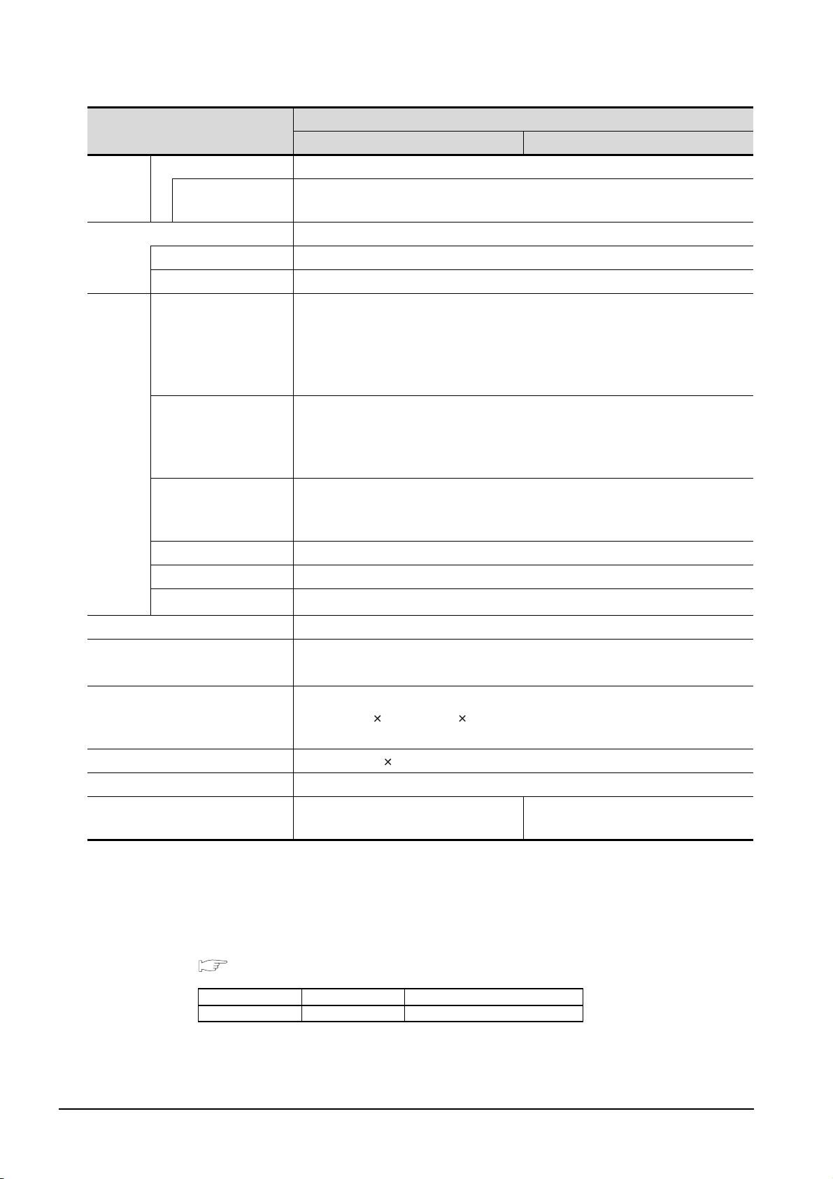
Item
GT1595-XTBA GT1595-XTBD
C drive Built-in flash memory 9Mbytes (for storing project data and OS)
Memory
*4
Life (Number of
write times)
100,000 times
Battery GT15-BAT lithium battery (Option)
Backup target Clock data and maintenance time notification data
Life Approx. 5 years (Operating ambiant temperature of 25°C)
RS-232, 1ch
Transmission speed: 115,200/57,600/38,400/19,200/9,600/4,800 bps
RS-232
*6
Connector shape: D-sub 9-pin (Male)
Application: For communicating with a controller or connecting a personal
computer (Project data upload/download, OS installation, FA transparent function)
USB (Full Speed 12Mbps), Device, 1ch
Connector shape: Mini-B
Application: For connecting a personal computer (Project data upload/download,
OS installation, FA transparent function)
Built-in
interface
USB
Compact flash slot, 1ch
CF card
Connector shape: TYPE I
Application: Data transfer, data storage
Option function board For option function board mounting, 1ch
Specifications
Multi-color display board For multi-color display board mounting, 1ch
Extension unit
*6
For communication unit/option unit mounting, 2ch
Buzzer output Single tone (tone length adjustable)
Protective structure
Outside the enclosure: IP67
*5
Inside the enclosure: IP2X
External dimensions
(Excluding USB environmental
397(15.6)(W) 296(11.7)(H) 61(2.40)(D)[mm](inch)
protection cover)
Panel cutting dimensions 383.5(15.1)(W) 282.5(11.1)(H)[mm](inch)
Weight 4.9kg (mounting fixtures are not included)
Compatible software package
(GT Designer2 Version)
*1 Bright dots (always lit) and dark dots (unlit) may appear on a liquid crystal display panel due to its characteristics.
It is impossible to completely avoid this symptom, as the liquid crystal display comprises of a great number of
display elements. Please note that these dots appear due to its characteristic and are not caused by product
defect.
*2 With the hardware version indicated below, it will be 256 colors when the multi-color display board is not installed.
For how to confirm the function version, refer to the following.
Appendix Confirming of Versions and Conformed Standards
2.17T or later 2.32J or later
3 - 3
Item Model Function version
GT1595 GT1595-XTBA A
*3 The GOT screen saving/backlight off function prevents images from becoming permanently etched on the display
screen and increases the backlight life.
*4 ROM in which new data can be written without deleting the written data.
3.2 Performance Specifications
3.2.1 GT1595-X
Page 53
*5 Compliant with IP67 when the USB environmental protection cover is attached. Compliant with IP2X at the USB
interface only when a USB cable is connected. Note that this does not guarantee all users' operation
environment.
*6 When using multiple extension units and a bar code reader, the total current of the extension units and bar code
reader must not be greater than the total current that the GOT can supply.
For current values of extension units and bar code reader and the total current that the GOT can supply, refer to
the following manual.
GT Designer2 Version Screen Design Manual (2.8 Multi-channel Function)
1
2
SYSTEM
OVERVIEW
CONFIGURATION
3
SPECIFICATIONS
4
EMC AND LOW
PART NAME AND
SETTINGS
5
VOLTAGE
6
INSTALLATION
7
WIRING
DIRECTIVE
3.2 Performance Specifications
3.2.1 GT1595-X
8
OPTION
3 - 4
Page 54
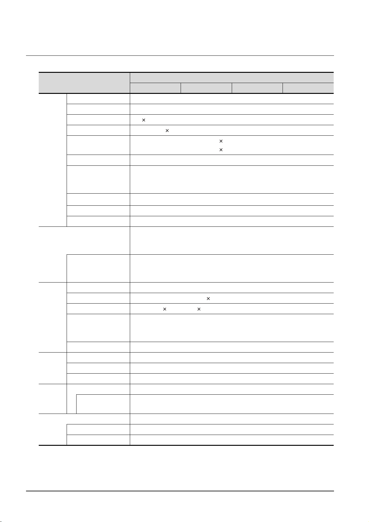
3.2.2 GT1585V-S, GT1585-S
Display
section*1
Backlight
Item
Type TFT color liquid crystal display (High intensity and wide angle view)
Screen size 12.1”
Resolution 800 600 dots
Display size 246(9.69)(W) 184.5(7.26)(H) [mm](inch)
Display character
Display color
Display angle
Intensity of LCD only
Intensity adjustment 8-level adjustment
Life Approx. 50,000 h (Operating ambient temperature: 25°C)
GT1585V-STBA GT1585V-STBD GT1585-STBA GT1585-STBD
16-dot standard font: 50 characters 37 lines (2byte character)
12-dot standard font: 66 characters 50 lines (2byte character)
65536 colors
Left/Right: 60 degrees
Top: 40 degrees
Bottom: 50 degrees
350 [cd/m
Cold cathode fluorescent tube (replaceable) backlight shutoff detection function is
included.
Backlight off/screen saving time can be set.
*2
2
]
Specifications
Approx. 50,000 h or longer
*3
Life
Type Matrix resistive film
Number of touch keys 1,900 objects/screen (38 lines 50 columns)
Touch
panel
Human
Sensor
Memory
Battery GT15-BAT lithium battery (Option)
Key size Minimum 16 16 dots (16 8 dots for the last line only) (per key)
Number of objects that
can be simultaneously
touched
Life 1 million times or more (operating force 0.98N max.)
Detection length 1(39.37) [m](inch)
Detection range Left/Right/Top/Bottom: 70 degrees
Detection delay time 0 to 4s
C drive Built-in flash memory 9Mbytes (for storing project data and OS)
*4
Life (Number of
write times)
Backup target Clock data and maintenance time notification data
Life Approx. 5 years (Operating ambient temperature of 25
(Time when display luminance reaches 50% at the operating ambient temperature
of 25
°C)
Maximum of 2 objects
100,000 times
°C)
3 - 5
(Continued to next page)
3.2 Performance Specifications
3.2.2 GT1585V-S, GT1585-S
Page 55
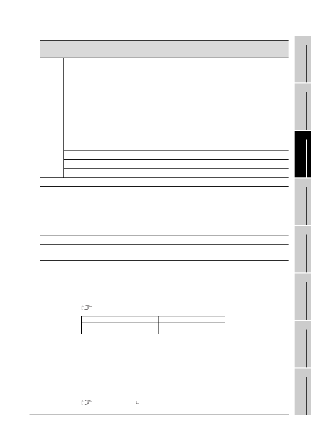
Item
RS-232
Built-in
interface
Buzzer output Single tone (tone length adjustable)
Protective structure
USB
CF card
Option function board For option function board mounting, 1ch
Multi-color display board For multi-color display board mounting, 1ch
Extension unit
*6
*6
GT1585V-STBA GT1585V-STBD GT1585-STBA GT1585-STBD
RS-232, 1ch
Transmission speed: 15,200/57,600/38,400/19,200/9,600/4,800 bps
Connector shape: D-sub 9-pin (Male)
Application: For communicating with a controller or connecting a personal
computer (Project data upload/download, OS installation, FA transparent function)
USB (Full Speed 12Mbps), Device, 1ch
Connector shape: Mini-B
Application: For connecting a personal computer (Project data upload/download,
OS installation, FA transparent function)
Compact flash slot, 1ch
Connector shape: TYPE I
Application: Data transfer, data storage
For communication unit/option unit mounting, 2ch
Outside the enclosure: IP67
Inside the enclosure: IP2X
*5
Specifications
1
2
SYSTEM
3
4
OVERVIEW
CONFIGURATION
SPECIFICATIONS
External dimensions
(Excluding USB environmental
protection cover)
Panel cutting dimensions 302(11.89)(W) × 228(8.98)(H)[mm](inch)
Weight 2.8 kg (mounting fixtures are not included)
Compatible software package
(GT Designer2 Version)
*1 Bright dots (always lit) and dark dots (unlit) may appear on a liquid crystal display panel due to its characteristics.
It is impossible to completely avoid this symptom, as the liquid crystal display comprises of a great number of
display elements. Please note that these dots appear due to its characteristic and are not caused by product
defect.
*2 With the hardware version indicated below, it will be 256 colors when the multi-color display board is not installed.
For how to confirm the function version, refer to the following.
Appendix Confirming of Versions and Conformed Standards
Item Model Function version
GT1585
*3 The GOT screen saving/backlight off function prevents images from becoming permanently etched on the display
screen and increases the backlight life.
*4 ROM in which new data can be written without deleting the written data.
*5 Compliant with IP67 when the USB environmental protection cover is attached. Compliant with IP2X at the USB
interface only when a USB cable is connected. Note that this does not guarantee all users' operation
environment.
*6 When using multiple extension units and a bar code reader, the total current of the extension units and bar code
reader must not be greater than the total current that the GOT can supply.
For current values of extension units and bar code reader and the total current that the GOT can supply, refer to
the following manual.
GT Designer2 Version Screen Design Manual (2.8 Multi-channel Function)
316(12.44)(W) × 242(9.53)(H) × 52(2.05)(D) [mm](inch)
2.32J or later 2.04E or later 2.17T or later
GT1585-STBA A
GT1585-STBD A
3.2 Performance Specifications
3.2.2 GT1585V-S, GT1585-S
3 - 6
EMC AND LOW
PART NAME AND
SETTINGS
5
VOLTAGE
6
INSTALLATION
7
WIRING
8
OPTION
DIRECTIVE
Page 56
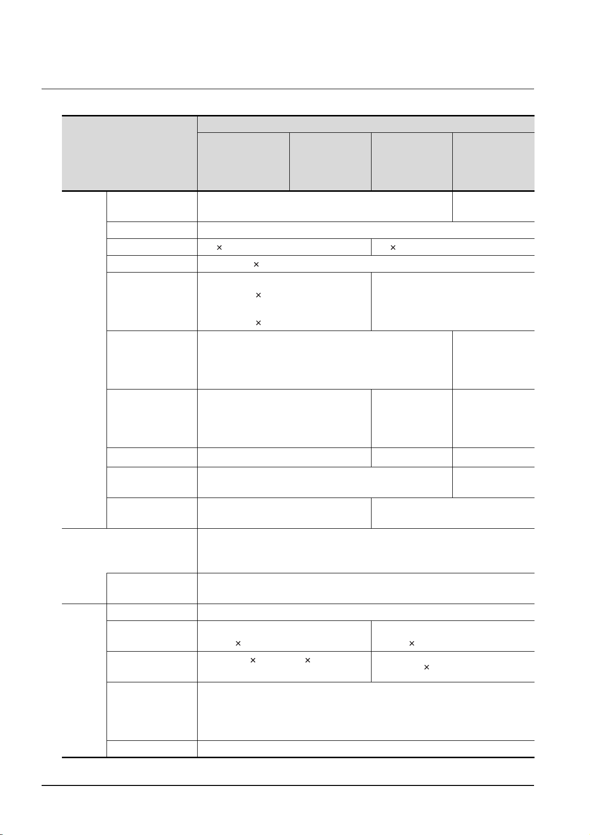
3.2.3 GT1575V-S, GT1575-S, GT1575-V, GT1575-VN, GT1572-VN
Specifications
GT1575-VNBA,
Item
Type
Screen size 10.4"
Resolution 800 600dots 640 480dots
Display size 211(8.31)(W) 158(6.22)(H)[mm](inch)
GT1575V-STBA,
GT1575V-STBD
TFT color liquid crystal (LCD of high intensity and wide angle
view)
GT1575-STBA,
GT1575-STBD
GT1575-VTBA,
GT1575-VTBD
GT1575-VNBD,
GT1572-VNBA,
TFT color liquid
crystal
GT1572-VNBD
Display
section
Backlight
16-dot standard font:
Display character
Display color
*1
Display angle
Intensity of LCD only
Intensity adjustment 8-level adjustment
Life
50 characters 37 lines (2byte character)
12-dot standard font:
66 characters 50 lines (2byte character)
65536 colors
Left/Right/Top/
Bottom:
85 degrees
400[cd/m
Approx. 50,000 h
(Operating ambient temparature: 25°C)
Cold cathode fluorescent tube (replaceable) backlight shutoff detection function is
included.
Backlight off/screen saving time can be set.
16-dot standard font: 40
characters 30 lines (2byte character)
12-dot standard font: 53
characters 40 lines (2byte character)
GT1575-VN:
*2
Left/ Right/Top/
Bottom:
85 degrees
2
] 380[cd/m2] 200[cd/m2]
Approx. 41,000 h
(Operating ambient temparature:25°C)
256color
GT1572-VN:
16color
Left/Right: 45
degrees
Top: 30 degrees
Bottom: 20 degrees
4-level
adjustment
3 - 7
Touch
panel
*3
Life
Type Matrix resistive film
Number of touch keys
Key size
Number of objects
that can be
simultaneously
touched
Life 1 million times or more (operating force 0.98 max.)
3.2 Performance Specifications
3.2.3 GT1575V-S, GT1575-S, GT1575-V, GT1575-VN, GT1572-VN
Approx. 40,000 h or longer (Time when display luminance reaches 50% at the
operating ambient temperature of 25°C)
1,900 objects/screen
(38 lines 50 columns)
Minimum 16 16 dots (16 8 dots for the
last line only)(per key)
Maximum of 2 objects
1,200 objects/screen
(30 lines 40 columns)
Minimum 16 16 dots (per key)
(Continued to next page)
Page 57
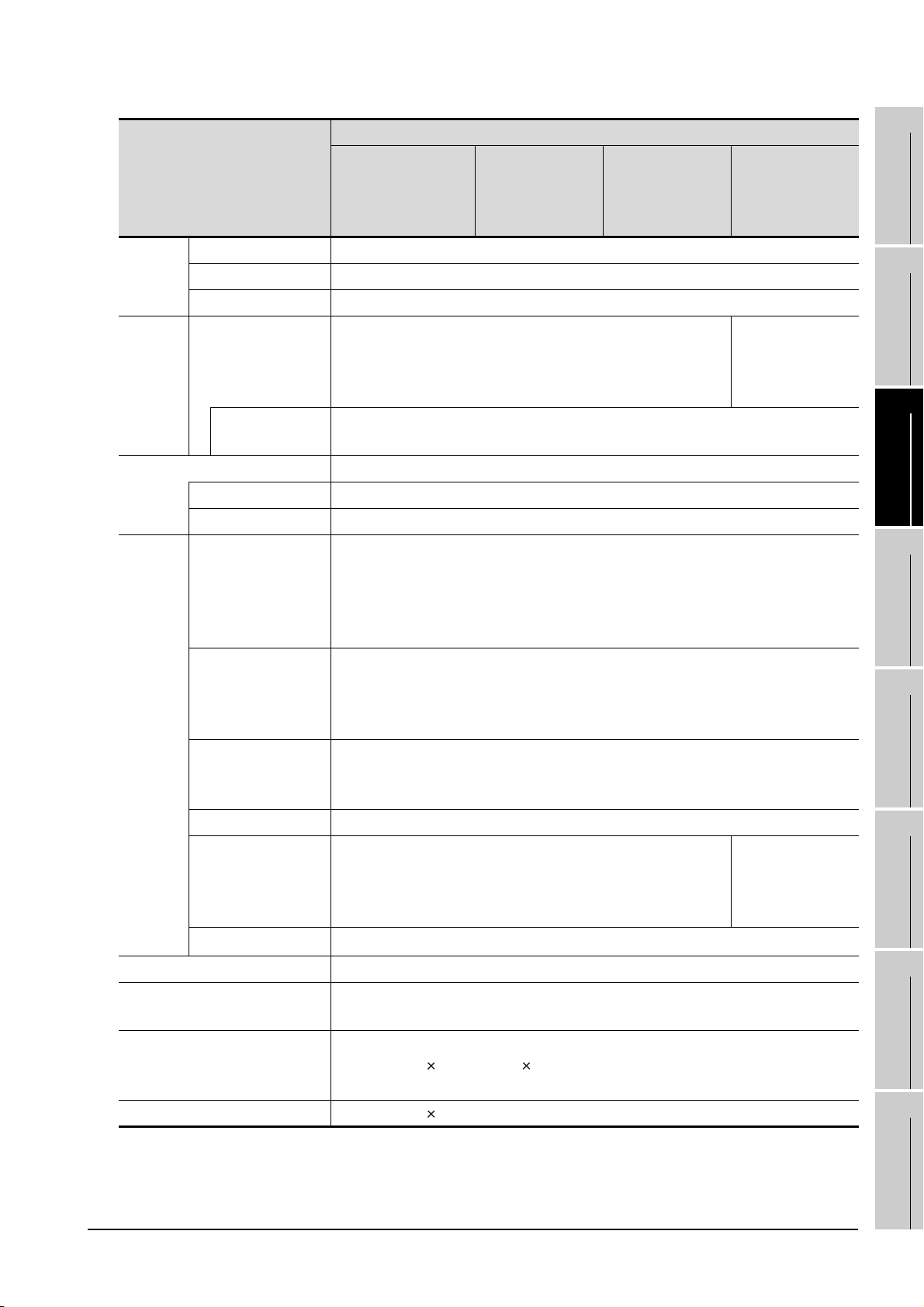
Specifications
Item
Detection length None
Human
sensor
Memory
Batery GT15-BAT lithium battery (Option)
Built-in
interface
Buzzer output Single tone (tone length adjustable)
Protective structure
External dimensions
(Excluding USB environmental
protective cover)
Panel cutting dimensions 289(11.38)(W) 200(7.87)(H)[mm](inch)
Detection range None
Detection delay time None
C drive
*4
Life (Number of
write times)
Backup target Clock data and maintenance time notification data
Life Approx. 5 years (Operating ambient temperature of 25°C)
RS-232
USB
CF card
Option function board For option function board mounting, 1ch
Multi-color display
board
Extension unit
*6
*6
GT1575V-STBA,
GT1575V-STBD
Built-in flash memory 9Mbytes
(for storing project data and OS)
100,000 times
RS-232, 1ch
Transmission speed: 115,200/57,600/38,400/19,200/9,600/4,800 bps
Connector shape: D-sub 9-pin (Male)
Application: For communicating with a controller or connecting a personal computer
(Project data upload/download, OS installation, FA transparent function)
USB (Full Speed 12 Mbps), Device, 1ch
Connector shape: Mini-B
Application: For connecting a personal computer (Project data upload/download, OS
installation, FA transparent function)
Compact flash slot, 1ch
Connector shape: TYPE I
Application: Data transfer, data storage
For multi-color display board mounting, 1ch
For communication unit/option unit mounting, 2ch
Outside the enclosure: IP67*5
Inside the enclosure: IP2X
303(11.93)(W) 214(8.43)(H) 49(1.93)(D)[mm](inch)
GT1575-STBA,
GT1575-STBD
GT1575-VTBA,
GT1575-VTBD
GT1575-VNBA,
GT1575-VNBD,
GT1572-VNBA,
GT1572-VNBD
Built-in flash
memory 5Mbytes
(for storing project
data and OS)
Cannot be used.
(Even installed,
65536 colors will
not be displayed.)
EMC AND LOW
1
OVERVIEW
2
SYSTEM
CONFIGURATION
3
SPECIFICATIONS
4
PART NAME AND
SETTINGS
5
VOLTAGE
6
INSTALLATION
7
WIRING
8
DIRECTIVE
(Continued to next page)
3.2 Performance Specifications
3.2.3 GT1575V-S, GT1575-S, GT1575-V, GT1575-VN, GT1572-VN
OPTION
3 - 8
Page 58
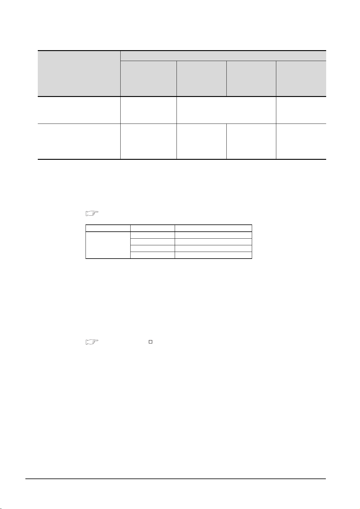
Item
GT1575V-STBA,
GT1575V-STBD
Specifications
GT1575-STBA,
GT1575-STBD
GT1575-VTBA,
GT1575-VTBD
GT1575-VNBA,
GT1575-VNBD,
GT1572-VNBA,
GT1572-VNBD
Weight
Compatible software package
(GT Designer2 Version)
*1 Bright dots (always lit) and dark dots (unlit) may appear on a liquid crystal display panel due to its characteristics.
*2 With the hardware version indicated below, it will be 256 colors when the multi-color display board is not installed.
*3 The GOT screen saving/backlight off function prevents images from becoming permanently etched on the display
*4 ROM in which new data can be written without deleting the written data.
*5 Compliant with IP67 when the USB environmental protection cover is attached. Compliant with IP2X at the USB
*6 When using multiple extension units and a bar code reader, the total current of the extension units and bar code
2.3 kg
(mounting fixtures are
not included)
2.32J or later
It is impossible to completely avoid this symptom, as the liquid crystal display comprises of a great number of
display elements. Please note that these dots appear due to its characteristic and are not caused by product
defect.
For how to confirm the function version, refer to the following.
Appendix Confirming of Versions and Conformed Standards
Item Model Function version
GT1575-STBA A
GT1575
screen and increases the backlight life.
interface only when a USB cable is connected. Note that this does not guarantee all users' operation
environment.
reader must not be greater than the total current that the GOT can supply.
For current values of extension units and bar code reader and the total current that the GOT can supply, refer to
the following manual.
GT Designer2 Version Screen Design Manual (2.8 Multi-channel Function)
GT1575-STBD A
GT1575-VTBA A
GT1575-VTBD A
2.4 kg
(mounting fixtures are not included)
GT1575-STBA:
2.04E or later
GT1575-STBD:
2.17T or later
GT1575-VTBA:
2.04E or later
GT1575-VTBD:
2.17T or later
2.3 kg (mounting
fixtures are not
included)
2.17T or later
3 - 9
3.2 Performance Specifications
3.2.3 GT1575V-S, GT1575-S, GT1575-V, GT1575-VN, GT1572-VN
Page 59
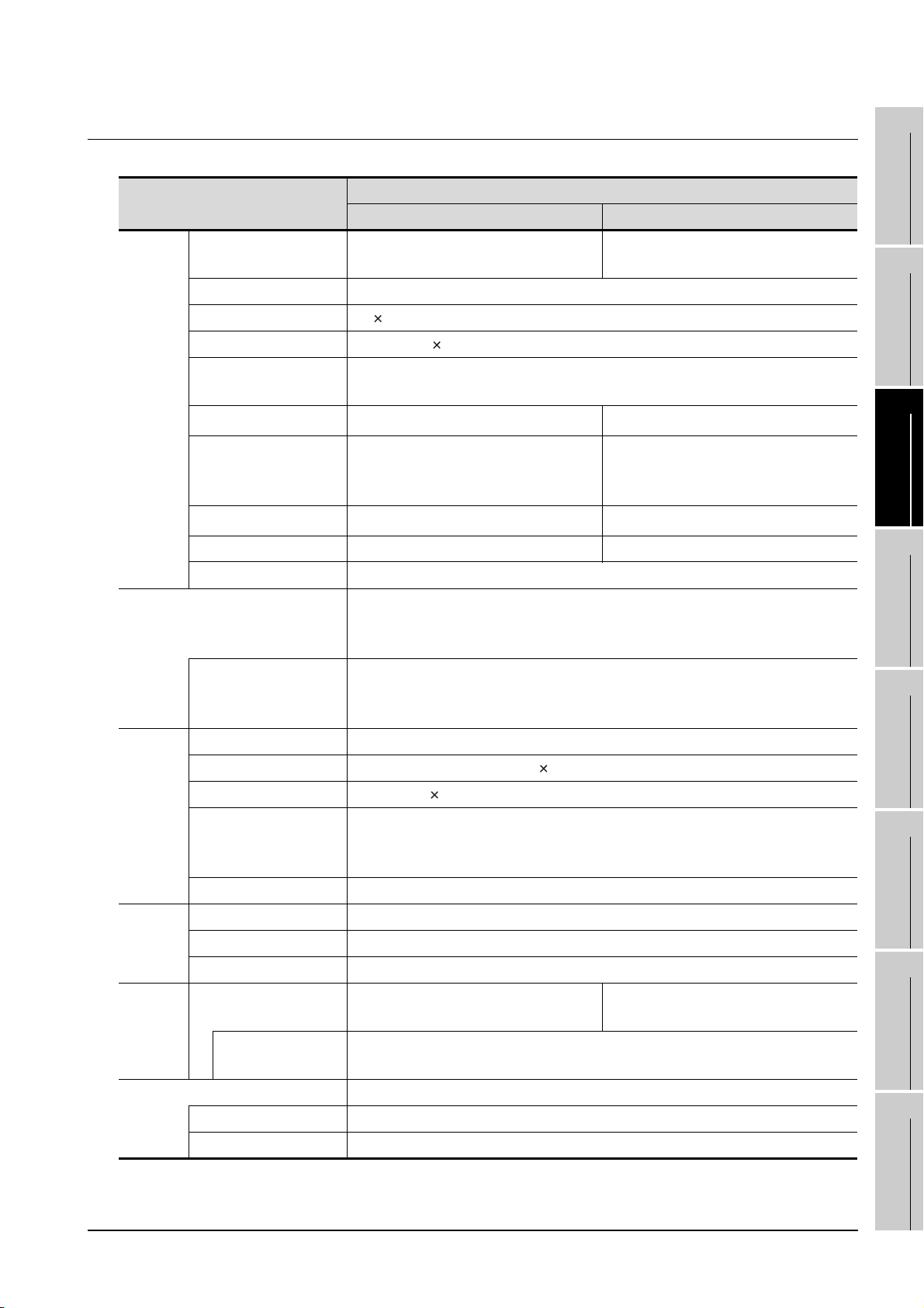
3.2.4 GT1565-V, GT1562-VN
1
Display
section
Backlight
Item
Type
Screen size 8.4"
Resolution 640 480dots
Display size 171(6.73)(W) 128(5.04)(H)[mm](inch)
Display character
*1
Display color
Display angle
Intensity of LCD only
Intensity adjustment 8-level adjustment 4-level adjustment
Life Approx. 41,000 h (Operating ambient temperature: 25°C)
*3
Life
Type Matrix resistive film
GT1565-VTBA, GT1565-VTBD GT1562-VNBA, GT1562-VNBD
TFT color liquid crystal (LCD of high
intensity and wide angle view)
16-dot standard font: 40 characters × 30 lines (2byte character)
12-dot standard font: 53 characters × 40 lines (2byte character)
65536 colors
Left/Right: 65degrees
Top: 50 degrees
Bottom: 60 degrees
380[cd/m
Cold cathode fluorescent tube (replaceable) backlight shutoff detection function is
included.
Backlight off/screen saving time can be set.
Approx. 40,000 h or longer
(Time when display luminance reaches 50% at the operating ambient temperature
of 25°C)
*2
2
] 150[cd/m2]
Specifications
TFT color liquid crystal
16 colors
Left/Right: 45degrees
Top: 20 degrees
Bottom: 20 degrees
OVERVIEW
2
SYSTEM
CONFIGURATION
3
SPECIFICATIONS
4
PART NAME AND
SETTINGS
5
Number of touch keys 1,200 objects/screen (30 lines 40 columns)
Touch
panel
Human
sensor
Memory
Battery GT-15BAT lithium battery (Option)
Key size Minimum 16 16 dots (per key)
Number of objects that
can be simultaneously
touched
Life 1 million times or more (operating force 0.98N max.)
Detection length None
Detection range None
Detection delay time None
C drive
*4
Life (Number of
write times)
Backup target Clock data and maintenance time notification data
Life Approx. 5 years (Operating ambient temperature of 25°C)
Maximum of 2 objects
Built-in flash memory 9Mbytes
(for string project data and OS)
100,000 times
Built-in flash memory 5Mbytes
(for string project data and OS)
(Continued to next page)
EMC AND LOW
VOLTAGE
6
INSTALLATION
7
WIRING
8
DIRECTIVE
3.2 Performance Specifications
3.2.4 GT1565-V, GT1562-VN
OPTION
3 - 10
Page 60
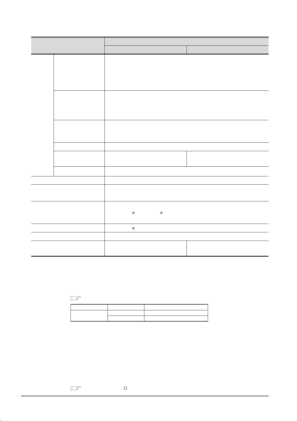
Item
Specifications
GT1565-VTBA, GT1565-VTBD GT1562-VNBA, GT1562-VNBD
RS-232, 1ch
Transmission speed: 115,200/57,600/38,400/19,200/9,600/4,800 bps
RS-232
*6
Connector shape: D-sub 9-pin (Male)
Application: For communicating with a controller or connecting a personal
computer (Project data upload/download, OS installation, FA transparent function)
USB (Full Speed 12 Mbps), Device, 1ch
USB
Built-in
interface
Connector shape: Mini-B
Application: For connecting a personal computer (Project data upload/download,
OS installation, FA transparent function)
Compact flash slot, 1ch
CF card
Connector shape: TYPE 1
Application: Data transfer, data storage
Option function board For option function board mounting, 1ch
Multi-color display board
Extension unit
*6
For multi-color display board mounting,
1ch
For communication unit/option unit mounting, 2ch
Buzzer output Single tone (tone length adjustable)
Protective structure
Outside the enclosure: IP67
*5
Inside the enclosure: IP2X
External dimensions
(Excluding USB environmental
241(9.49)(W) 190(7.48)(H) 52(2.05)(D)[mm](inch)
protective cover)
Panel cutting dimensions 227(8.94)(W) 176(6.93)(H)[mm](inch)
Weight 1.9 kg (mounting fixtures are not included)
Cannot be used. (Even installed, 65536
colors will not be displayed.)
Compatible software package
(GT Designer2 Version)
*1 Bright dots (always lit) and dark dots (unlit) may appear on a liquid crystal display panel due to its characteristics.
It is impossible to completely avoid this symptom, as the liquid crystal display comprises of a great number of
display elements. Please note that these dots appear due to its characteristic and are not caused by product
defect.
*2 With the hardware version indicated below, it will be 256 colors when the multi-color display board is not installed.
For how to confirm the function version, refer to the following.
Appendix Confirming of Versions and Conformed Standards
Item Model Function version
GT1565
*3 The GOT screen saving/backlight off function prevents images from becoming permanently etched on the display
screen and increases the backlight life.
*4 ROM in which new data can be written without deleting the written data.
*5 Compliant with IP67 when the USB environmental protection cover is attached. Compliant with IP2X at the USB
interface only when a USB cable is connected. Note that this does not guarantee all users' operation
environment.
*6 When using multiple extension units and a bar code reader, the total current of the extension units and bar code
reader must not be greater than the total current that the GOT can supply.
For current values of extension units and bar code reader and the total current that the GOT can supply, refer to
the following manual.
GT Designer2 Version Screen Design Manual (2.8 Multi-channel Function)
GT1565-VTBA: 2.04E or later,
GT1565-VTBD: 2.17T or later
GT1565-VTBA A
GT1565-VTBD A
2.17T or later
3 - 11
3.2 Performance Specifications
3.2.4 GT1565-V, GT1562-VN
Page 61
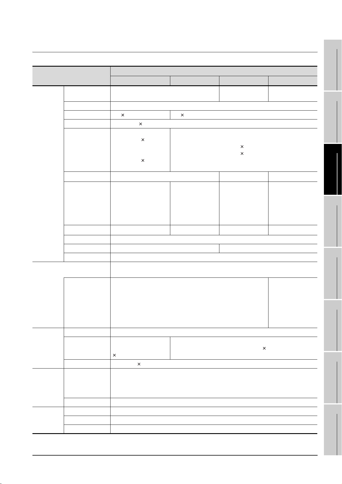
3.2.5 GT1555-V, GT1555-Q, GT1550-Q
1
Display
section
*1
Backlight
Touch panel
Touch panel
*6
Human
sensor
Item
Specifications
GT1555-VTBD GT1555-QTBD GT1555-QSBD GT1550-QLBD
Type
Screen size 5.7"
Resolution 640 480dots 320 240dots
Display size 115(4.53)(W) 86(3.39)(H)[mm](inch)
Display character
Display color
Display angle
Intensity of LCD only
Intensity adjustment 8-level adjustment
Contrast adjustment None 16-level adjustment
Life Approx. 50,000 h (Operating ambient temperature: 25°C)
*2
Life
Type Matrix resistive film
Number of touch keys
Key size Minimum 16 16 dots (per key)
Number of objects
that can be
simultaneously
touched
Life 1 million times or more (operating force 0.98N max.)
Detection length None
Detection range None
Detection delay time None
TFT color liquid crystal
(LCD of high intensity and wide angle view)
16-dot standard font:
40 characters 30 lines
(2byte characters)
12-dot standard font:
53 characters 40 lines
(2byte characters)
65536color
Left/Right:
80 degrees
Top:
80 degrees
Bottom:
70 degrees
350[cd/m2] 400[cd/m2] 380[cd/m2] 220[cd/m2]
Cold cathode fluorescent tube (nonreplaceable) backlight shutoff detection function is included.
Backlight off/screen saving time can be set.
Approx. 75,000 h or longer
(Time when display luminance reaches 50% at the operating ambient
temperature of 25°C)
1200 objects/screen
(Matrix structure of 30 lines
40 columns)
Maximum of 2 objects
*2
16-dot standard font: 20 characters 15 lines (2byte characters)
12-dot standard font: 26 characters 20 lines (2byte characters)
Left/Right:
70 degrees
Top:
70 degrees
Bottom:
50 degrees
300 objects/screen (Matrix structure of 15 lines 20 columns)
STN color liquid crystal
4096color monochrome (16-level)
Left/Right:
55 degrees
To p:
65 degrees
Bottom:
70 degrees
STN monochrome
liquid crystal
Left/Right:
45 degrees
To p:
20 degrees
Bottom:
40 degrees
Approx. 58,000 h or
longer
(Time when display
luminance reaches
50% at the operating
ambient temperature of
25°C)
(Continued to next page)
EMC AND LOW
OVERVIEW
2
SYSTEM
CONFIGURATION
3
SPECIFICATIONS
4
PART NAME AND
SETTINGS
5
VOLTAGE
6
INSTALLATION
7
WIRING
8
DIRECTIVE
3.2 Performance Specifications
3.2.5 GT1555-V, GT1555-Q, GT1550-Q
OPTION
3 - 12
Page 62
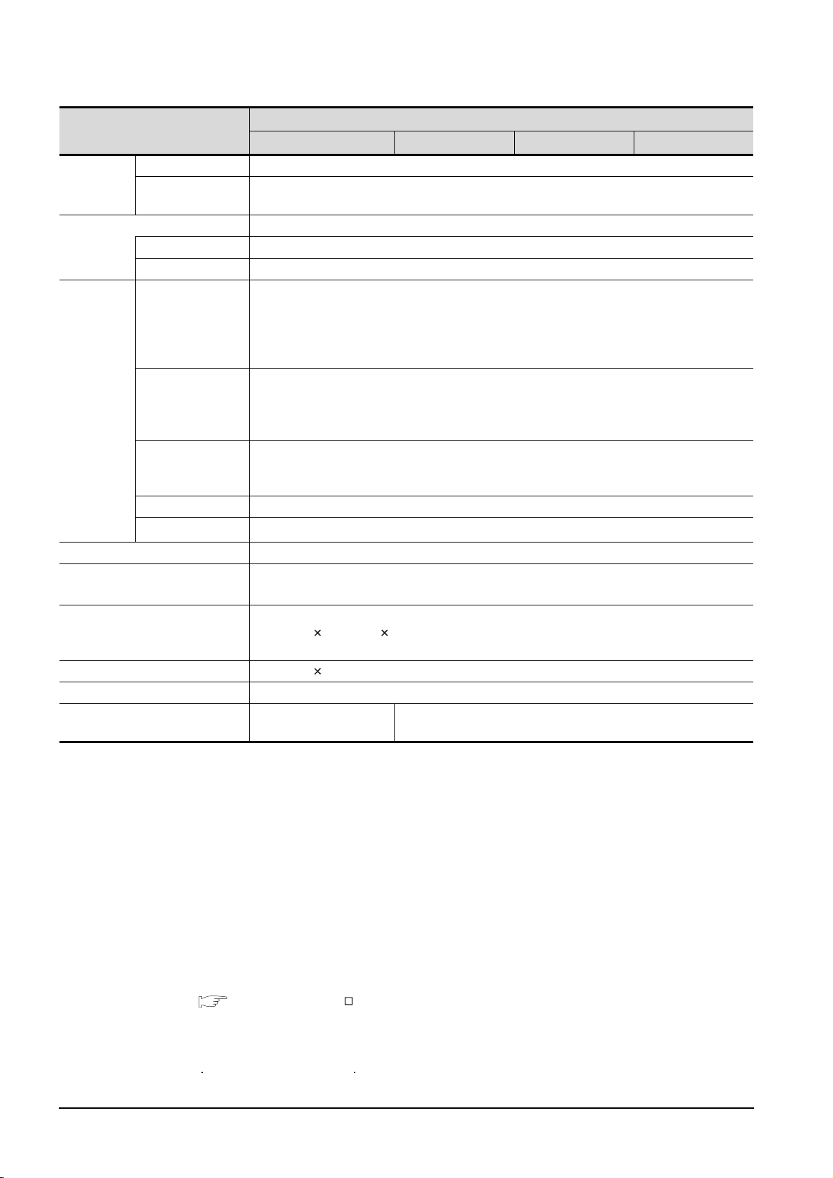
Item
GT1555-VTBD GT1555-QTBD GT1555-QSBD GT1550-QLBD
Memory
*3
Battery GT15-BAT lithium battery (Option)
Built-in
interface
Buzzer output Single tone (tone length adjustable)
Protective structure
External dimensions
(Excluding USB environmental
protective cover)
Panel cutting dimensions 153(6.0)(W) 121(4.8)(H)[mm](inch)
Weight 1.1 kg (mounting fixtures are not included)
Compatible software package
(GT Designer2 Version)
C drive Built-in flash memory 9Mbytes (for string project data and OS)
Life (Number of write
times)
Backup target Clock data and maintenance time notification data
Life Approx. 5 years (Operating ambient temperature of 25°C)
*5
RS-232
USB
CF card
Option function board For option function board mounting, 1ch
Extension unit
*5
100,000 times
RS-232, 1ch
Transmission speed: 115,200/57,600/38,400/19,200/9,600/4,800 bps
Connector shape: D-sub 9-pin (Male)
Application: For communicating with a controller or connecting a personal computer (Project data upload/
download, OS installation and FA transparent function)
USB (Full Speed 12 Mbps), Device, 1ch
Connector shape: Mini-B
Application: For connecting a personal computer (Project data upload/download, OS installation and FA
transparent function)
Compact flash slot, 1ch
Connector shape: TYPE 1
Application: Data transfer, data storage
For communication unit/option unit mounting, 1ch
Outside the enclosure: IP67
Inside the enclosure: IP2X
167(6.6)(W) 135(5.3)(H) 56(2.2)(D)[mm](inch)
2.58L or later 2.32J or later
*4
Specifications
3 - 13
*1 Bright dots (always lit) and dark dots (unlit) may appear on a liquid crystal display panel due to its characteristics.
It is impossible to completely avoid this symptom, as the liquid crystal display comprises of a great number of
display elements. Flickers may be observed depending on the display color. Please note that these dots and
flickers appear due to its characteristic and are not caused by product defect.
*2 The GOT screen saving/backlight off function prevents images from becoming permanently etched on the display
screen and increases the backlight life.
*3 ROM in which new data can be written without deleting the written data.
*4 Compliant with IP67 when the USB environmental protection cover is attached. Compliant with IP2X at the USB
interface only when a USB cable is connected. Note that this does not guarantee all users' operation
environment.
*5 When using multiple extension units and a bar code reader, the total current of the extension units and bar code
reader must not be greater than the total current that the GOT can supply.
For current values of extension units and bar code reader and the total current that the GOT can supply, refer to
the following manual.
GT Designer2 Version Screen Design Manual (2-8 Multi-channel Function)
*6 The GT1555-V can be operated with a stylus pen.
With a stylus pen, small-sized touch switches can be certainly operated.
Use a stylus pen that satisfies the following specifications.
Material: Polyacetal resin Pen tip radius: 0.8mm or more
3.2 Performance Specifications
3.2.5 GT1555-V, GT1555-Q, GT1550-Q
Page 63
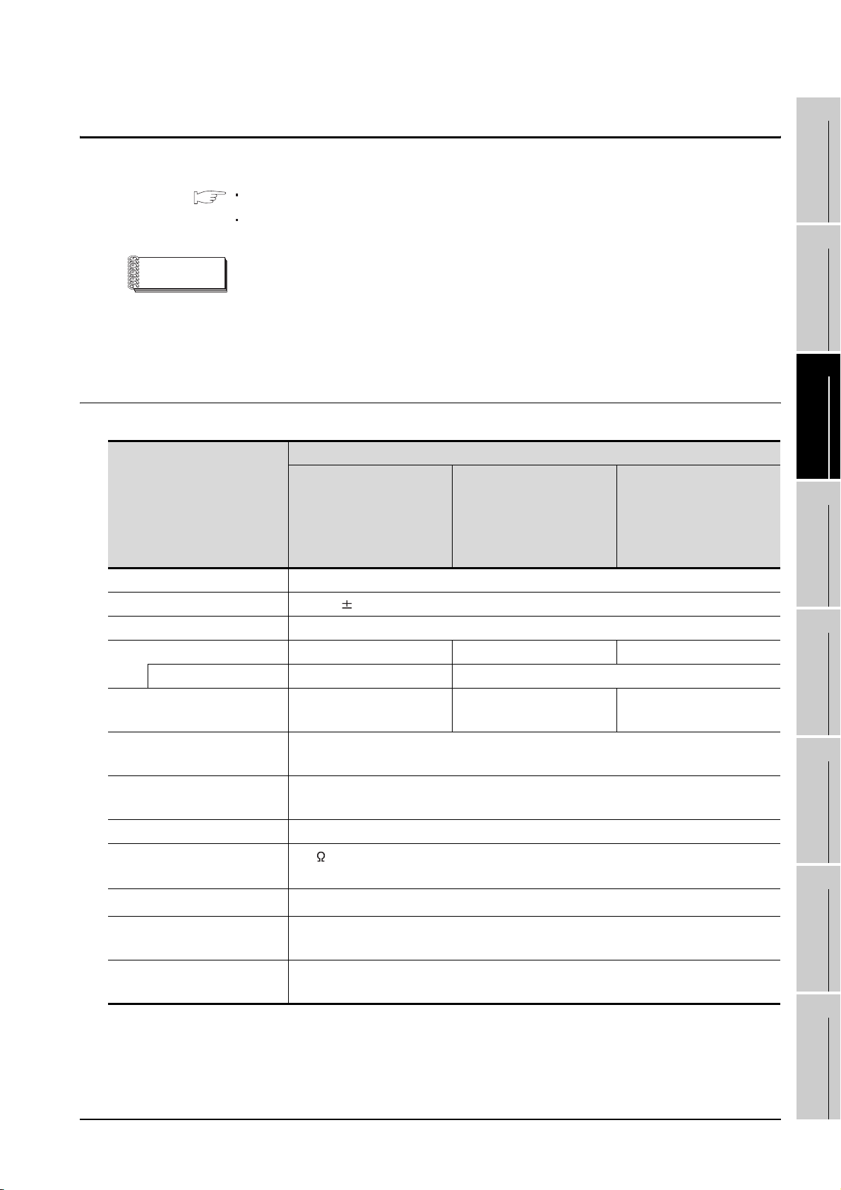
3.3 Power Supply Specifications
The following describes the power supply specifications for the GT15.
3.3.1 For GOTs powered from the 100 to 240VAC power supply
3.3.2 For GOTs powered from the 24VDC power supply
1
OVERVIEW
2
Remark
Operation at momentary failure
• If an instantaneous power failure occurs in the power supply and continues
for more than the permissible period, the GOT will be reset.
• Make sure to power on the unit more than 5 seconds after power-off.
3.3.1 For GOTs powered from the 100 to 240VAC power supply
Specifications
Item
Input power supply voltage 100 to 240VAC (+10% -15%)
Input frequency 50/60Hz 5%
Input max. apparent power 110VA (maximum load)
Power consumption 56W or less 41W or less 39W or less
At backlight off 30W or less 28W or less
Inrush current
Permissible instantaneous
power failure time
GT1595-XTBA
50A or less (4ms)
(maximum load)
20ms or less (100VAC or more)
GT1585V-STBA,
GT1585-STBA
45A or less (4ms)
(maximum load)
40A or less (4ms)
(maximum load)
GT1575V-STBA, GT1575-
STBA, GT1575-VTBA,
GT1575-VNBA, GT1572-
VNBA, GT1565-VTBA,
GT1562-VNBA
EMC AND LOW
SYSTEM
CONFIGURATION
3
SPECIFICATIONS
4
PART NAME AND
SETTINGS
5
VOLTAGE
6
DIRECTIVE
Noise immunity
Dielectric withstand voltage 1500VAC for 1 minute across power terminals and earth
Insulation resistance
Applicable wire size
Applicable solderless terminal
Applicable tightening torque
(Terminal block terminal screw)
1,500Vp-p noise voltage, 1µs noise width (when measuring with a noise simulator
under 25 to 60Hz noise frequency)
10M or more across power terminals and earth by a 500V DC insulation resistance
tester
0.75 to 2 [mm
Solderless terminal for M3 screw RAV1.25-3, V2-S3.3, V2-N3A,
FV2-N3A
0.5 to 0.8 [N•m]
3.3.1 For GOTs powered from the 100 to 240VAC power supply
2
]
3.3 Power Supply Specifications
INSTALLATION
7
WIRING
8
OPTION
3 - 14
Page 64
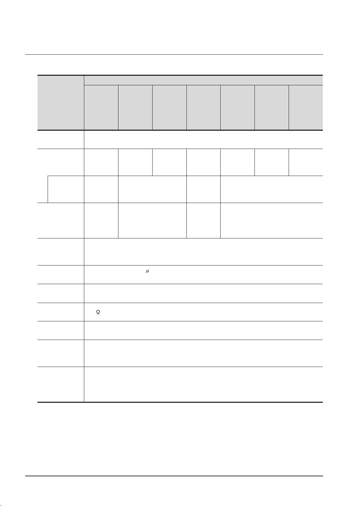
3.3.2 For GOTs powered from the 24VDC power supply
Specifications
GT1575V-STBD,
GT1575-STBD,
Item
Input power
supply voltage
Power
consumption
At backlight
off
Inrush current
GT1595-XTBD
GT1585V-STBD,
GT1585-STBD
24VDC (+25%, -20%)
57W or less
(2380mA/
24VDC)
32W or less
(1330mA/
24VDC)
43W or less
(1790mA/
24VDC)
30W or less
(1250mA/24VDC)
100A or less
(4ms)
(maximum
115 A o r l e s s
(1ms)(maximum load)
load)
GT1575-VTBD,
GT1575-VNBD,
GT1572-VNBD,
GT1565-VTBD,
GT1562-VNBD
41W or less
(1710mA/
24VDC)
GT1555-V GT1555-QTBD GT1555-QSBD GT1550-QLBD
19W or less
(790mA/
24VDC)
18W or less
(750mA/
24VDC)
14W or less
(580mA/
13W or less (540mA/24VDC)
24VDC)
67A or less
(1ms)(maxim
60A or less (1ms)(maximum load)
um load)
17W or less
(710mA/
24VDC)
15W or less
(620mA/
24VDC)
Permissible
instantaneous
power failure time
Noise immunity
Dielectric
withstand voltage
Insulation
resistance
Applicable wire
size
Applicable
solderless
terminal
Applicable
tightening torque
(Terminal block
terminal screw)
10 ms or less
500Vp-p noise voltage, 1 s noise width (when measuring with a noise simulator under 25 to 60Hz
noise frequency)
500VAC for 1 minute across power terminals and earth
10M or more across power terminals and earth by a 500V DC insulation resistance tester
0.75 to 2 [mm²]
Solderess terminal for M3 screw RAV1.25-3, V2-S3.3, V2-N3A, FV2-N3A
0.5 to 0.8 [N•m]
3 - 15
3.3 Power Supply Specifications
3.3.2 For GOTs powered from the 24VDC power supply
Page 65
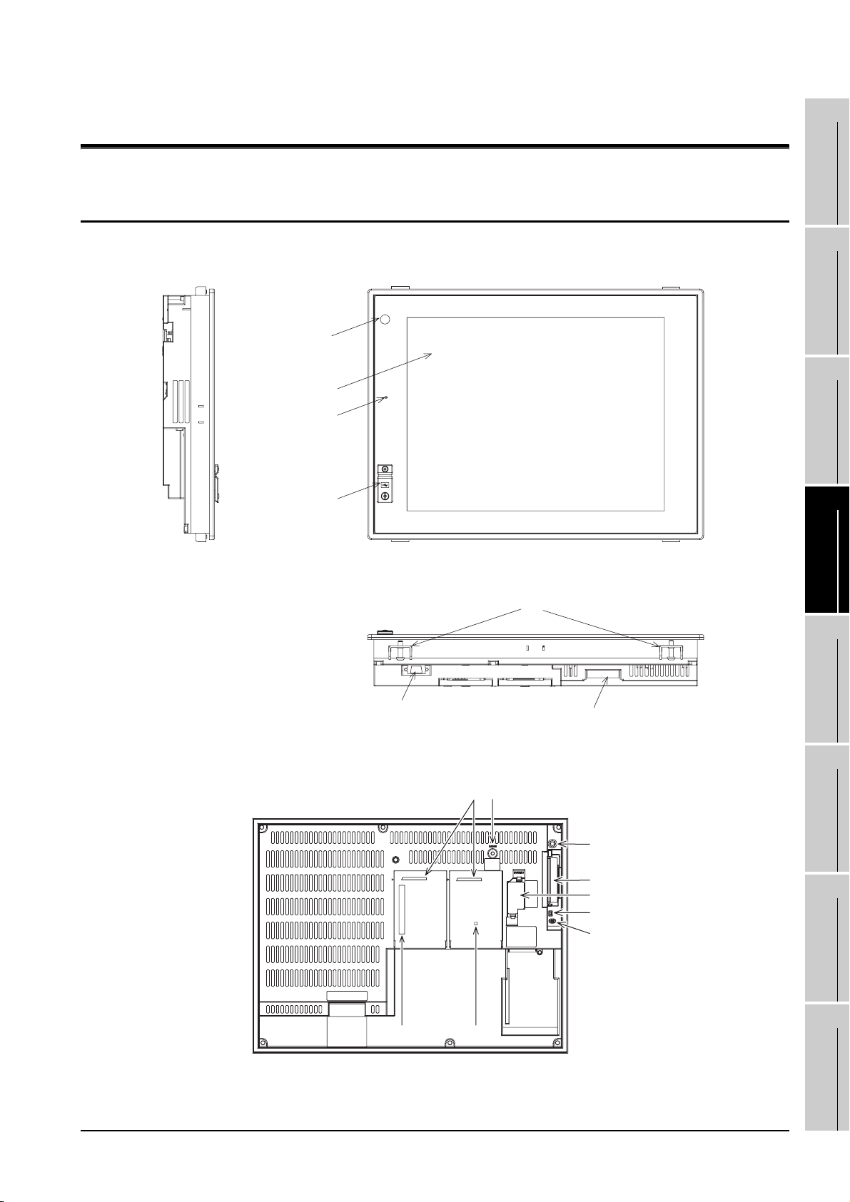
4. PART NAME AND SETTINGS
1
4.1 Part Names and Settings of the GT1595
16)
2), 3)
1)
4)
14)
OVERVIEW
2
SYSTEM
CONFIGURATION
3
SPECIFICATIONS
4
PART NAME AND
SETTINGS
5
5)
GOT rear face
11)
4.1 Part Names and Settings of the GT1595
7)
12)
13)
6)
17)
15)
10)
8)
9)
4 - 1
EMC AND LOW
VOLTAGE
6
INSTALLATION
7
WIRING
8
OPTION
DIRECTIVE
Page 66
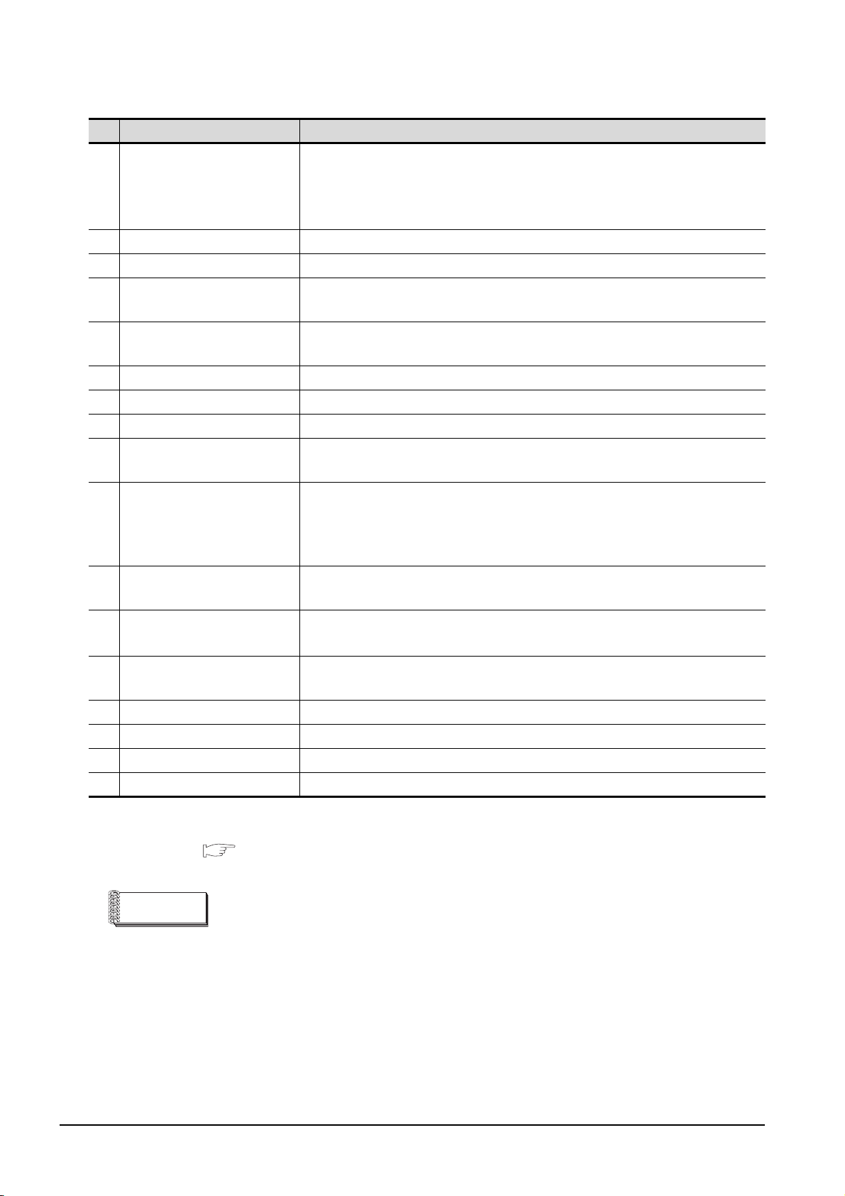
No. Name Description
Lit in green : Power is correctly supplied
1) POWER LED
2) Display screen Displays the Utility and the user creation screen.
3) Touch key For operating the touch switches in the Utility and the user creation screen
4) USB interface
5) RS-232 interface
6) Power terminal Power input terminal, LG terminal, FG terminal
7) Extension unit interface For installing an extension unit
8) CF card interface For installing a CF card
Lit in orange : Screen saving
Blinks in orange/green : Blown back light bulb
Not lit : Power is not supplied
For connecting a personal computer
(Connector type: MINI-B)
For communicating with a controller or connecting a personal computer
(Connector type: D sub 9-pin)
9) CF card access LED
10) CF card access switch
Optional function board
11)
interface
Multi-color display board
12)
interface
13) Reset switch
14) Hole for unit installation fitting Hole for inserting the unit installation fitting
15) Battery holder Houses the battery.
16) Human sensor Sensor that detects human movement
17) Installation switch Used for OS installations at the GOT startup
*1
*1 For the multi-color display board, refer to the following.
3.2.1 GT1595-X
Lit : CF card accessed
Not lit: CF card not accessed
Used for stopping the access to the CF card before removing the CF card from the
GOT
ON : CF card being accessed (CF card removal prohibited)
OFF : CF card not accessed (CF card removal possible)
For installing the optional function board
For installing the multi-color display board
Hardware reset switch
(Inoperative in the bus connection or with the bus connection unit installed)
4 - 2
Remark
Connector used for the RS-232 interface
The specification of the cconnector used for the RS-232 interface of GT1595 is as
follows.
Manufacturer :DDK Ltd.
Mode name :17LE-23090-27 (D4CK) or equivalent product
4.1 Part Names and Settings of the GT1595
Page 67
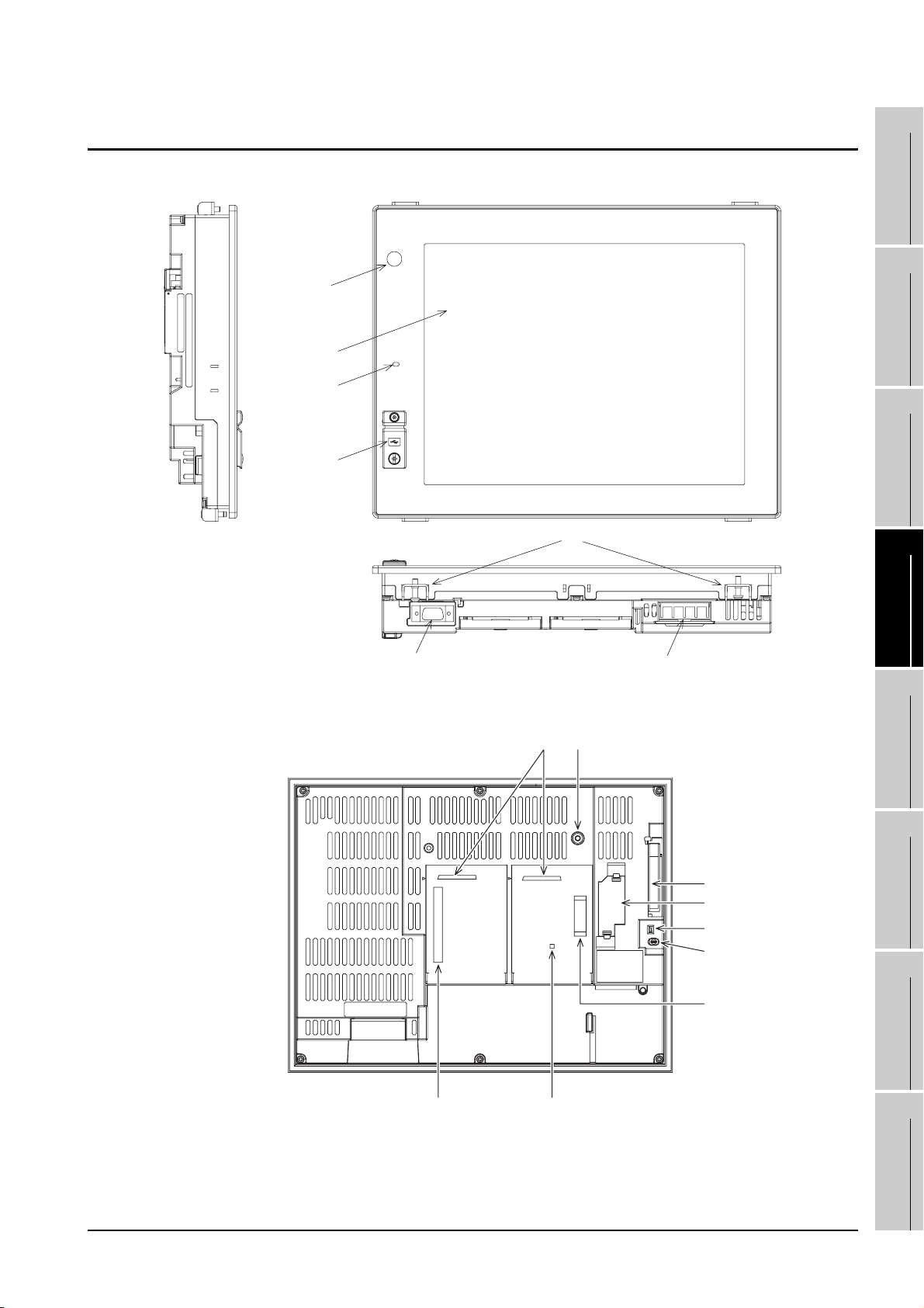
4.2 Part Names and Settings of the GT1585
17)
2), 3)
1)
5)
15)
1
2
SYSTEM
3
4
OVERVIEW
CONFIGURATION
SPECIFICATIONS
6) 7)
GOT rear face
12)
14)8)
13)
9)
16)
10)
11)
4)
EMC AND LOW
PART NAME AND
SETTINGS
5
VOLTAGE
6
INSTALLATION
7
WIRING
8
DIRECTIVE
4.2 Part Names and Settings of the GT1585
OPTION
4 - 3
Page 68
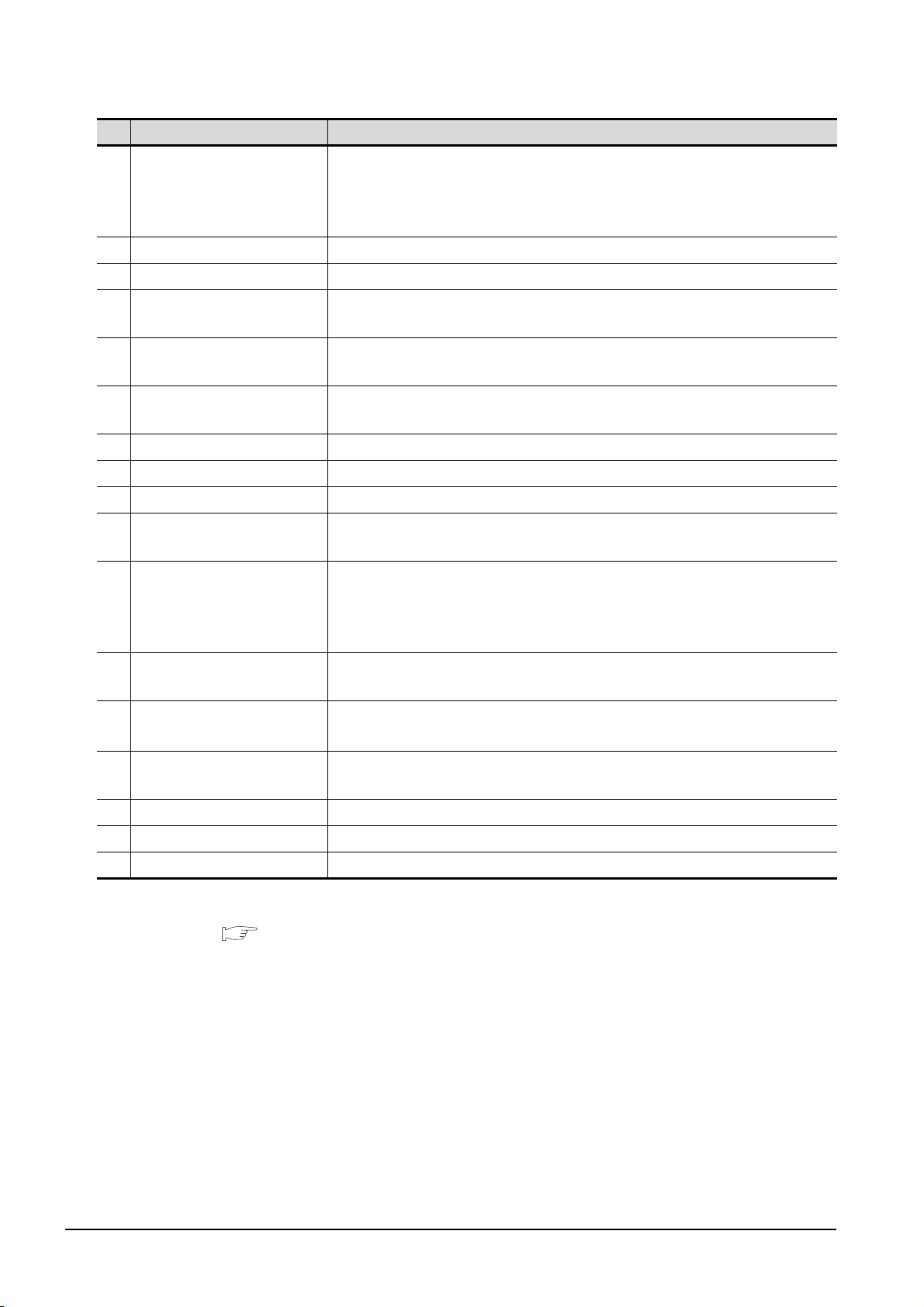
No. Name Description
Lit in green : Power is correctly supplied
1) POWER LED
Lit in orange : Screen saving
Blinks in orange/green : Blown back light bulb
Not lit : Power is not supplied
2) Display screen Displays the utility and the user creation screen.
3) Touch key For operating the touch switches in the utility and the user creation screen
4)
Video/RGB interface
5) USB interface
6) RS-232 interface
*1
For installing the video input unit, RGB input unit, video/RGB input unit, or RGB
output unit
For connecting a personal computer
(Connector type: MINI-B)
For communicating with a controller or connecting a personal computer
(Connector type: D sub 9-pin)
7) Power terminal Power input terminal, LG terminal, FG terminal
8) Extension unit interface For installing an extension unit
9) CF card interface For installing a CF card
10) CF card access LED
Lit : CF card accessed
Not lit: CF card not accessed
Used for stopping the access to the CF card before removing the CF card from the
11) CF card access switch
GOT
ON : CF card being accessed (CF card removal prohibited)
OFF : CF card not accessed (CF card removal possible)
Optional function board
12)
interface
Multi-color display board
13)
interface
*2
For installing the optional function board
For installing the multi-color display board
14) Reset switch
Hardware reset switch
(Inoperative in the bus connection or with the bus connection unit installed)
15) Hole for unit installation fitting Hole for inserting the unit installation fitting
16) Battery holder Houses the battery.
17) Human sensor Sensor that detects human movement
*1 It is provided for the GT1585V-S only.
*2 For the multi-color display board, refer to the following.
3.2.2 GT1585V-S, GT1585-S
4 - 4
4.2 Part Names and Settings of the GT1585
Page 69
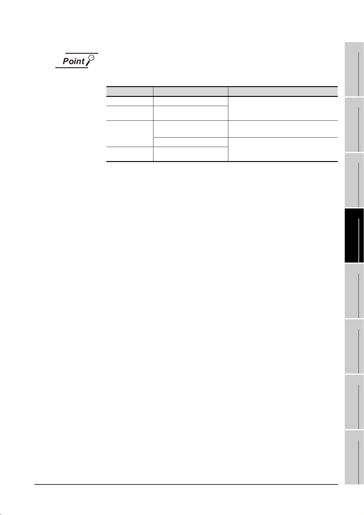
Connector used for the RS-232 interface
The specification of the connector used for the RS-232 interface of GT1585 is as
follows.
1
GOT model name Hardware version Connector
GT1585V-STBA A (March, 2006) or later Manufacturer: DDK Ltd.
GT1585V-STBD A (May, 2006) or later
GT1585-STBA
GT1585-STBD A (July, 2005) or later
B (April, 2005) or before
C (April, 2005) or later Manufacturer: DDK Ltd.
Model name: 17LE-23090-27 (D4CK) or equivalent
product
Manufacturer: Honda Tsushin Kogyo Co., Ltd.
Model name: GM-C9RMDU11 or equivalent product
Model name: 17LE-23090-27 (D4CK) or equivalent
product
OVERVIEW
2
SYSTEM
CONFIGURATION
3
SPECIFICATIONS
4
PART NAME AND
SETTINGS
EMC AND LOW
5
VOLTAGE
6
INSTALLATION
7
WIRING
8
DIRECTIVE
4.2 Part Names and Settings of the GT1585
OPTION
4 - 5
Page 70
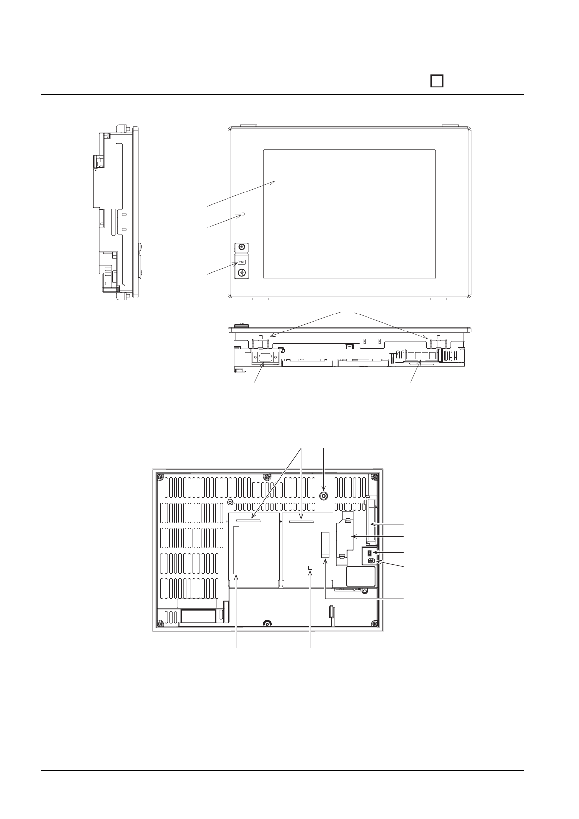
4.3 Part Names and Settings of the GT157
2), 3)
1)
5)
15)
6)
GOT rear face
8)
12) 13)
7)
14)
9)
16)
10)
11)
4)
4 - 6
4.3 Part Names and Settings of the GT157
Page 71
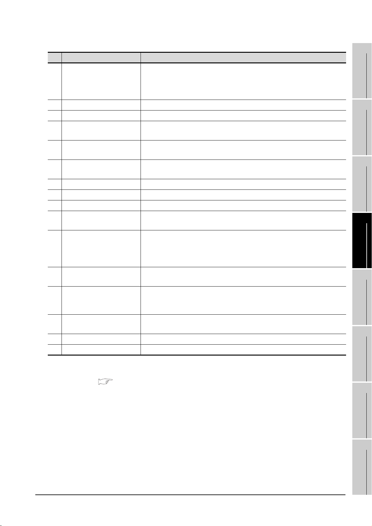
No. Name Description
Lit in green : Power is correctly supplied
1) POWER LED
2) Display screen Displays the utility and the user creation screen.
3) Touch key For operating the touch switches in the utility and the user creation screen
4)
Video/RGB interface
5) USB interface
6) RS-232 interface
7) Power terminal Power input terminal, LG terminal, FG terminal
8) Extension unit interface For installing an extension unit
9) CF card interface For installing a CF card
10) CF card access LED
11) CF card access switch
Optional function board
12)
interface
Multi-color display board
13)
interface
14) Reset switch
15) Hole for unit installation fitting Hole for inserting the unit installation fitting
16) Battery holder Houses the battery.
*2
*1
Lit in orange : Screen saving
Blinks in orange/green : Blown back light bulb
Not lit : Power is not supplied
For installing the video input unit, RGB input unit, video/RGB input unit, or RGB
output unit
For connecting a personal computer
(Connector type: MINI-B)
For communicating with a controller or connecting a personal computer
(Connector type: D sub 9-pin)
Lit : CF card accessed
Not lit : CF card not accessed
Used for stopping the access to the CF card before removing the CF card from the
GOT
ON : CF card being accessed (CF card removal prohibited)
OFF : CF card not accessed (CF card removal possible)
For installing the optional function board
For installing the multi-color display board
(For GT1575-VN and GT1572-VN, 65536 color display is not supported even with
the multi-color display board installed.)
Hardware reset switch
(Inoperative in the bus connection or with the bus connection unit installed)
EMC AND LOW
1
OVERVIEW
2
SYSTEM
CONFIGURATION
3
SPECIFICATIONS
4
PART NAME AND
SETTINGS
5
VOLTAGE
6
DIRECTIVE
*1 It is provided for the GT1575V-S only.
*2 For the multi-color display board, refer to the following.
3.2.3 GT1575V-S, GT1575-S, GT1575-V, GT1575-VN, GT1572-VN
INSTALLATION
7
WIRING
8
OPTION
4.3 Part Names and Settings of the GT157
4 - 7
Page 72
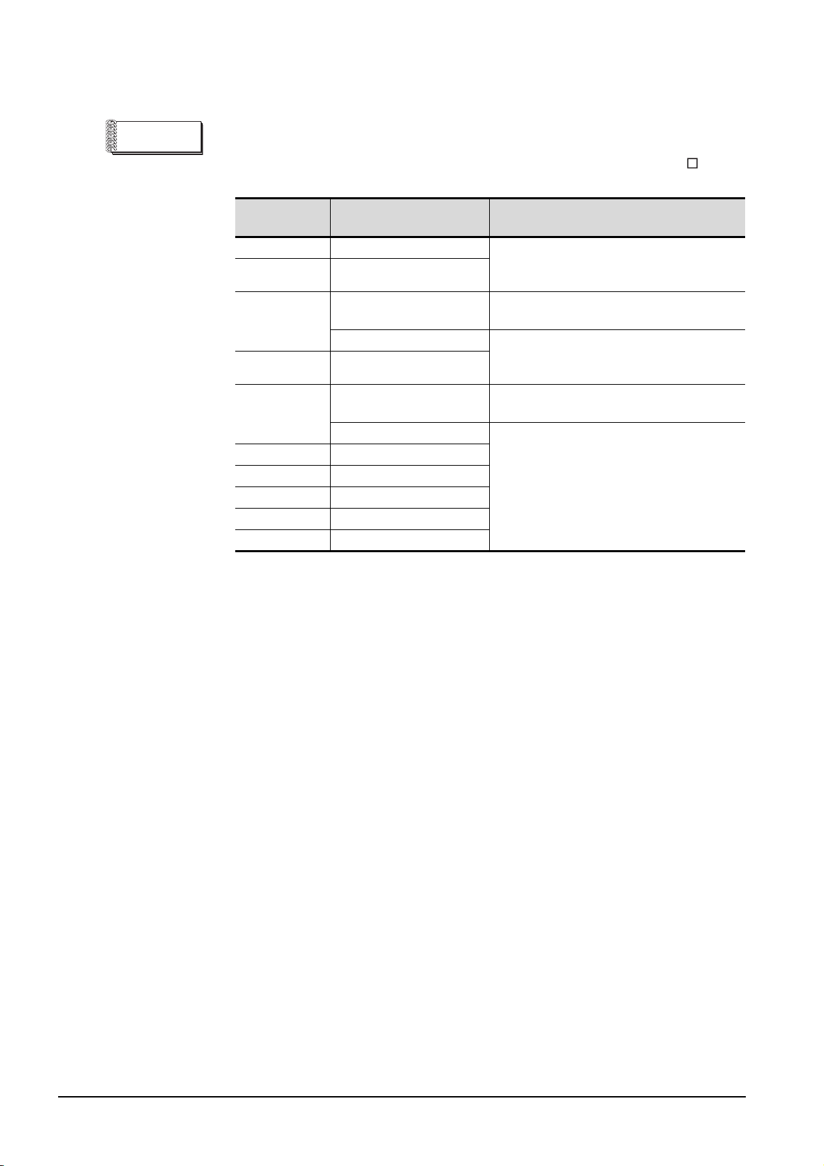
Remark
Connector used for the RS-232 interface
The specification of the connector used for the RS-232 interface of GT157 is as
follows.
GOT model
name
GT1575-STBA A (March, 2006) or later Manufacturer: DDK Ltd.
GT1575-STBD A (March, 2006) or later
GT1575-STBA
GT1575-STBD A (July, 2005) or later
GT1575-VTBA
GT1575-VTBD A (July, 2005) or later
GT1575-VNBA A (July, 2005) or later
GT1575-VNBD A (July, 2005) or later
GT1572-VNBA A (September, 2005) or later
GT1572-VNBD A (September, 2005) or later
Hardware version Connector
Model name: 17LE-23090-27 (D4CK) or equivalent
product
B (April, 2005) or before
C (April, 2005) or later Manufacturer: DDK Ltd.
D (April, 2005) or before
E (April, 2005) or later
Manufacturer: Honda Tsushin Kogyo Co., Ltd.
Model name: GM-C9RMDU11 or equivalent product
Model name: 17LE-23090-27 (D4CK) or equivalent
product
Manufacturer: Honda Tsushin Kogyo Co., Ltd.
Model name: GM-C9RMDU11 or equivalent product
Manufacturer: DDK Ltd.
Model name: 17LE-23090-27 (D4CK) or equivalent
product
4 - 8
4.3 Part Names and Settings of the GT157
Page 73
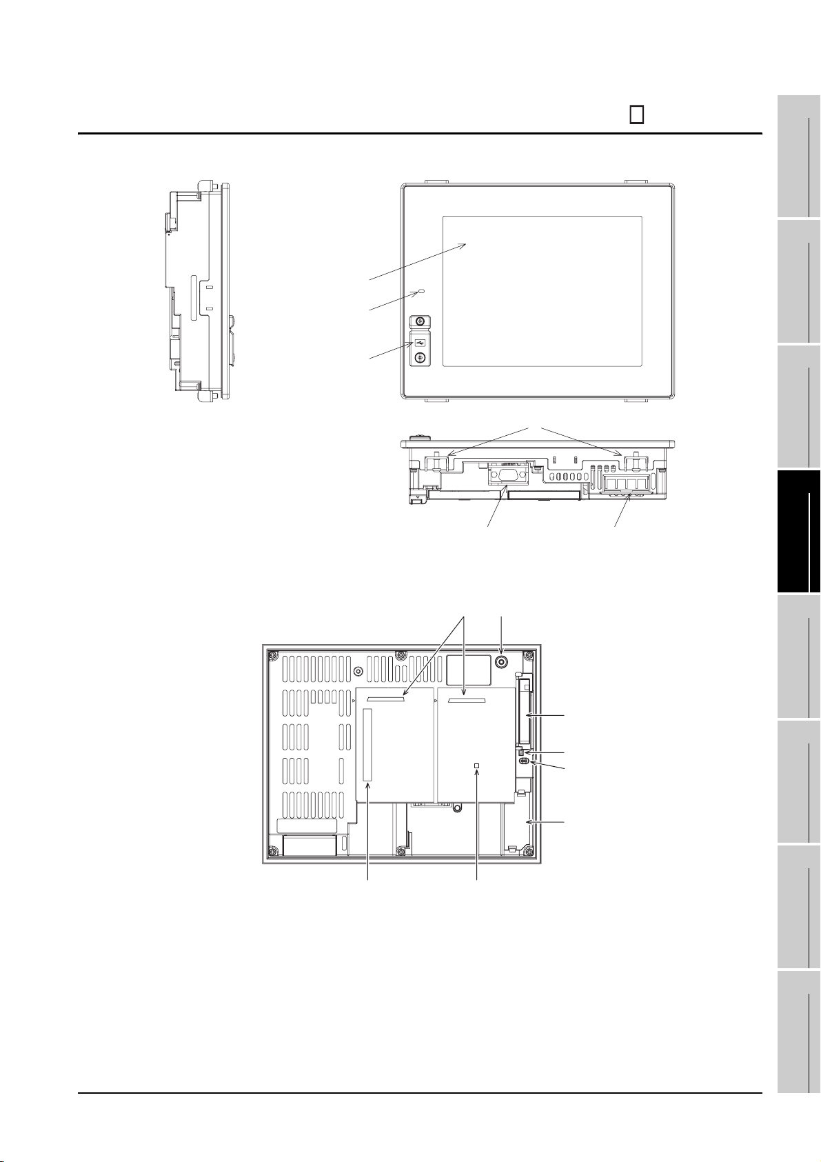
4.4 Part Names and Settings of the GT156
2) 3)
1)
1
2
SYSTEM
OVERVIEW
CONFIGURATION
4)
GOT rear face
5)
7) 13)
14)
8)
9)
10)
6)
EMC AND LOW
3
SPECIFICATIONS
4
PART NAME AND
SETTINGS
5
VOLTAGE
6
DIRECTIVE
11) 12)
4.4 Part Names and Settings of the GT156
15)
INSTALLATION
7
WIRING
8
OPTION
4 - 9
Page 74
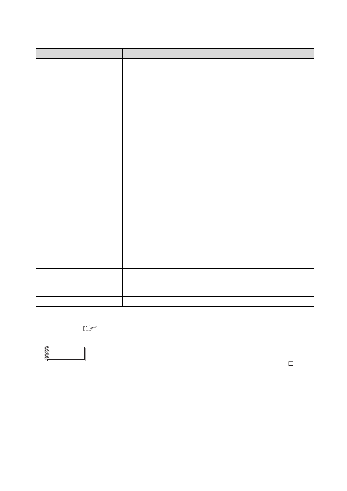
No. Name Description
Lit in green : Power is correctly supplied
1) POWER LED
2) Display screen Displays the utility and the user creation screen.
3) Touch key For operating the touch switches in the utility and the user creation screen
4) USB interface
5) RS-232 interface
6) Power terminal Power input terminal, LG terminal, FG terminal
7) Extension unit interface For installing an extension unit
8) CF card interface For installing a CF card
9) CF card access LED
10) CF card access switch
Optional function board
11)
interface
Lit in orange : Screen saving
Blinks in orange/green : Blown back light bulb
Not lit : Power is not supplied
For connecting a personal computer
(Connector type: MINI-B)
For communicating with a controller or connecting a personal computer
(Connector type: D sub 9-pin)
Lit : CF card accessed
Not lit : CF card not accessed
Used for stopping the access to the CF card before removing the CF card from the
GOT
ON : CF card being accessed (CF card removal prohibited)
OFF : CF card not accessed (CF card removal possible)
For installing the optional function board
Multi-color display board
12)
interface
13) Reset switch
14) Hole for unit installation fitting Hole for inserting the unit installation fitting
15) Battery holder Houses the battery.
Remark
*1
*1 For the multi-color display board, refer to the following.
3.2.4 GT1565-V, GT1562-VN
Connector used for the RS-232 interface
For installing the multi-color display board (For GT1562-VN, 65536 color display is
not supported even with the multi-color display board installed.)
Hardware reset switch
(Inoperative in the bus connection or with the bus connection unit installed)
The specification of the connector used for the RS-232 interface of GT156 is as
follows.
Manufacturer :DDK Ltd.
Mode name :17LE-23090-27 (D4CK) or equivalent product
4 - 10
4.4 Part Names and Settings of the GT156
Page 75
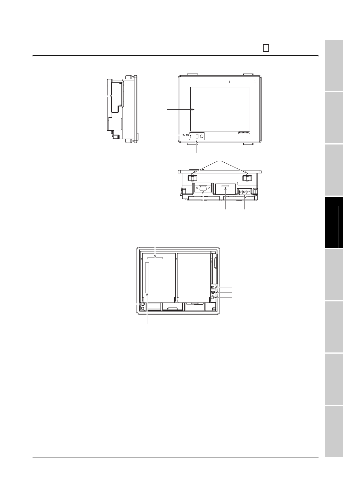
4.5 Part Names and Settings of the GT155
8)
2),3)
1
OVERVIEW
2
15)
1)
GOT rear face
7)
4)
13)
5) 14) 6)
9)
10)
12)
EMC AND LOW
SYSTEM
CONFIGURATION
3
SPECIFICATIONS
4
PART NAME AND
SETTINGS
5
VOLTAGE
6
DIRECTIVE
11)
4.5 Part Names and Settings of the GT155
INSTALLATION
7
WIRING
8
OPTION
4 - 11
Page 76
No. Name Description
Lit in green : Power is correctly supplied
1) POWER LED
2) Display screen Displays the Utility and the user creation screen
3) Touch key For operating touch switches in the Utility and the user creation screen
4) USB interface
5) RS-232 interface
6) Power terminal Power input terminal, FG terminal
7) Extension unit interface For installing an extension unit
8) CF card interface For installing a CF card
9) CF card access LED
10) CF card access switch
Optional function board
11)
interface
Lit in red : Screen saving
Blinks in red : Blown back light bulb
Not lit : Power is not supplied
For connecting a personal computer
(Connector type: MINI-B)
For communicating with a controller or connecting a personal computer
(Connector type: D sub 9-pin)
Lit : CF card accessed
Not lit : CF card not accessed
Used for stopping the access to the CF card before removing the CF card from the
GOT
ON : CF card being accessed (CF card removal prohibited)
OFF : CF card not accessed (CF card removal possible)
For installing the optional function board
12) Reset switch
13) Hole for unit installation fitting Hole for inserting the unit installation fitting
14) Battery holder Houses the battery
15) Protective ground terminal For earthing
Remark
Connector used for the RS-232 interface
Hardware reset switch
(Inoperative in the bus connection or with the bus connection unit installed)
The specification of the connector used for the RS-232 interface of GT155 is as
follows.
Manufacturer :DDK Ltd.
Mode name :17LE-23090-27 (D4CK) or equivalent product
4 - 12
4.5 Part Names and Settings of the GT155
Page 77
5. EMC AND LOW VOLTAGE DIRECTIVE
1
OVERVIEW
For the products sold in European countries, the conformance to the EMC Directive, which is one of the
European Directives, has been a legal obligation since 1996. Also, conformance to the Low Voltage
Directive, another European Directives, has been a legal obligation since 1997.
Manufacturers who recognize their products must conform to the EMC and Low Voltage Directive are
required to declare that their products conform to these Directives and put a "CE mark" on their products.
5.1 Requirements to Meet EMC Directive
EMC Directives are those which require "any strong electromagnetic force is not output to the external.:
Emission (electromagnetic interference)" and "It is not influenced by the electromagnetic wave from the
external.: Immunity (electromagnetic sensitivity)".
Items 5.1.1 thru 5.1.3 summarize the precautions to use GOT and configure the mechanical unit in order to
match the EMC directives.
Though the data described herein are produced with our best on the basis of the requirement items and
standards of the restrictions gathered by Mitsubishi, they do not completely guaranteed that all mechanical
unit manufactured according to the data do not always match the above directives. The manufacturer itself
which manufactures the mechanical unit must finally judge the method and others to match the EMC
directives.
2
SYSTEM
CONFIGURATION
3
SPECIFICATIONS
4
PART NAME AND
SETTINGS
5
5.1 Requirements to Meet EMC Directive
5 - 1
EMC AND LOW
VOLTAGE
6
INSTALLATION
7
WIRING
8
OPTION
DIRECTIVE
Page 78
5.1.1 EMC directive
The standards of the EMC Directive are shown below.
Applied standard Test standard Test details Standard value
30M-230MHz QP:
30dB V/m (30m in measurement
*2, *3
range)
230M-1000MHz QP:
37dB V/m(30m in measurement
*2, *3
range)
150k-500kHz QP:79dB,
Mean: 66dB
*2
500k-30MHz QP:73dB,
Mean: 60dB
*2
±4kV Contact discharge
±8kV Aerial discharge
80-1000MHz:10V/m
1.4-2GHz:10V/m
80%AM modulation@1kHz
Power line:2kV
Digital I/O(24V or higher): 1kV
(Digital I/O(24V or less))
> 250V
(Analog I/O, signal lines)
> 250V
AC power type
Power line (between line and ground)
: ±2kV
Power line (between lines)
: ±1kV
Data communication port
: ±1kV
DC power type
Power line (between line and ground)
: ±0.5kV
Power line (between lines)
: ±1kV
Power line: 3V
Data communication port: 3V
AC power type
0.5 cycle (interval 1s or more)
DC power type
10 ms (interval 1s or more)
EN61131-2 :2003
EN55011
Radiated noise
*1
EN55011
Conducted noise
*1
EN61000-4-2
Electrostatic immunity
*1
EN61000-4-3
Radiated field AM
modulation
*1
EN61000-4-4
Fast transient burst noise
*1
EN61000-4-5
Surge immunity
*1
EN61000-4-6
Conducted RF immunity
*1
Instantaneous power failure
and voltage dips immunity
Electromagnetic emissions
from the product are
measured.
Electromagnetic emissions
from the product to the
power line is measured.
Immunity test in which static
electricity is applied to the
cabinet of the equipment.
Immunity test in which field
is irradiated to the product.
Immunity test in which burst
noise is applied to the
power line and signal lines.
Immunity test in which
lightening surge is applied
to the product.
Immunity test in which a
noise inducted on the power
and signal lines is applied.
Test for checking normal
operations at instantaneous
power failure
5 - 2
(Continued to next page)
5.1 Requirements to Meet EMC Directive
5.1.1 EMC directive
Page 79
Applied standard Test standard Test details Standard value
AC power type
47Hz: 85V, 264V
63Hz: 85V, 264V
DC power type
20.4V, 28.8V
47Hz: 85V (phase 180
10%)
63Hz: 132V (phase 0
10.9%)
AC power type
47Hz: 85V
63Hz: 264V
DC power type
19.2V, 30V
°, distortion rate
°, distortion rate
EN61131-2 :2003
Test for checking normal
Radiated RF immunity
Third harmonic immunity
External power supply
fluctuation immunity
*1: The GOT is an open type device (device installed to another device) and must be installed in a conductive control
panel.
The above test items are conducted in the condition where the GOT is installed on the conductive control panel
and combined with the Mitsubishi PLC.
*2: QP: Quasi-peak value, Mean : Average value
*3: The above test items are conducted in the following conditions.
30M-230MHz QP: 40dB V/m (10m in measurement range)
230M-1000MHz QP: 47dB V/m (10m in measurement range)
operations when the power
supply unit input voltage is
fluctuated.
Test for checking normal
operations when the AC
power waveform mixed with
third harmonic wave is
input.
Test for checking if the unit
becomes faulty with a
transient voltage of the
internal and external input
sides of the power supply
unit or unit power supply.
1
OVERVIEW
2
SYSTEM
CONFIGURATION
3
SPECIFICATIONS
4
PART NAME AND
SETTINGS
5
5.1 Requirements to Meet EMC Directive
5.1.1 EMC directive
5 - 3
EMC AND LOW
VOLTAGE
6
INSTALLATION
7
WIRING
8
OPTION
DIRECTIVE
Page 80

5.1.2 Control panel
The GOT is an open type device (device installed to another device) and must be installed in a conductive
control panel.
It not only assure the safety but also has a large effect to shut down the noise generated from GOT, on the
control panel.
(1) Control panel
(a) The control panel must be conductive.
(b) When fixing a top or bottom plate of the control panel with bolts, do not coat the plate and bolt
surfaces so that they will come into contact.
And connect the door and box using a thick grounding cable in order to ensure the low
impedance under high frequency.
(c) When using an inner plate to ensure electric conductivity with the control panel, do not coat the
fixing bolt area of the inner plate and control panel to ensure conductivity in the largest area as
possible.
(d) Ground the control panel using a thick grounding cable in order to ensure the low impedance
under high frequency.
(e) The diameter of cable holes in the control panel must be 10cm (3.94in.). In order to reduce the
chance of radio waves leaking out, ensure that the space between the control panel and its
door is small as possible.
Attach some EMI gaskets to fill up the space and suppress the leakage of radio waves.
Out test have been carried out on a panel having the damping characteristics of 37dB max.
and 30dB mean (measured by 3m method with 30 to 300MHz).
(2) Connection of power and ground wires
Ground and power supply wires for the GOT must be connected as described below.
(a) Provide a grounding point near the GOT. Short-circuit the LG and FG terminals of the GOT
(LG: line ground, FG: frame ground) and ground them with the thickest and shortest wire
possible (The wire length must be 30cm (11.18in.) or shorter.) The LG and FG terminals
function is to pass the noise generated in the PC system to the ground, so an impedance that
is as low as possible must be ensured. As the wires are used to relieve the noise, the wire itself
carries a large noise content and thus short wiring means that the wire is prevented from
acting as an antenna.
Note) A long conductor will become a more efficient antenna at high frequency.
(b) The earth wire led from the earthing point must be twisted with the power supply wires. By
twisting with the earthing wire, noise flowing from the power supply wires can be relieved to the
earthing. However, if a filter is installed on the power supply wires, the wires and the earthing
wire may not need to be twisted.
5 - 4
5.1 Requirements to Meet EMC Directive
5.1.2 Control panel
Page 81
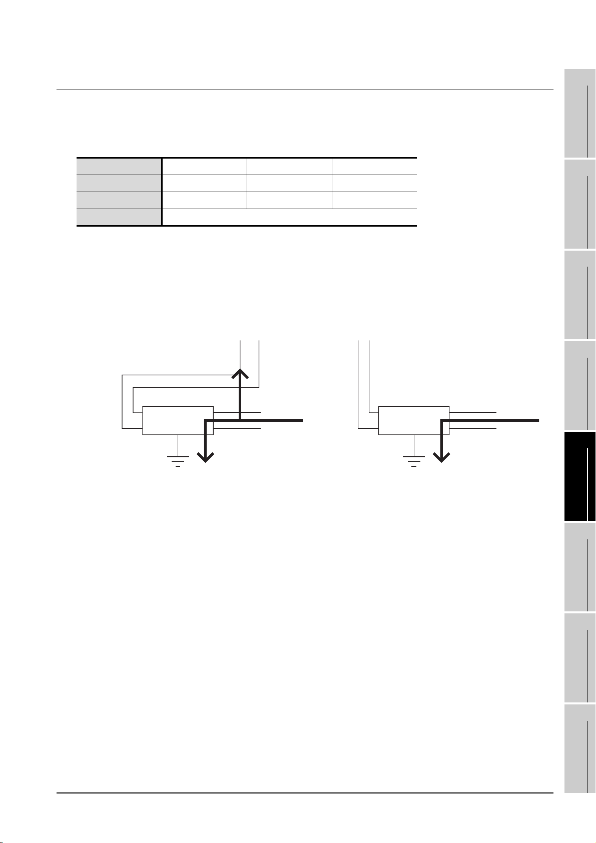
5.1.3 Noise filter (power supply line filter)
The noise filter (power supply line filter) is a device effective to reduce conducted noise. Except some
models, installation of a noise filter onto the power supply lines is not necessary. However conducted noise
can be reduced if it is installed. (The noise filter is generally effective for reducing conducted noise in the
band of 10MHz or less.) Usage of the following filters is recommended.
Model name FN343-3/01 FN660-6/06 ZHC2203-11
Manufacturer SCHAFFNER SCHAFFNER TDK
Rated current 3A 6A 3A
Rated voltage 250V
The precautions required when installing a noise filter are described below.
(1) Do not install the input and output cables of the noise filter together to prevent the output side noise
will be inducted into the input side cable where noise has been eliminated by the noise filer.
1
2
SYSTEM
3
OVERVIEW
CONFIGURATION
Input side
(power supply side)
Input side
(power supply side)
Induction
Filter
Output side
(device side)
(a) Installing the input and
output cables together will
cause noise induction.
(2) Connect the noise filter’s ground terminal to the control panel with the shortest cable as possible
(approx. 10cm (3.94 in.) or less).
Filter
Output side
(device side)
(b) Separate the input cable
from the output cable.
EMC AND LOW
SPECIFICATIONS
4
PART NAME AND
SETTINGS
5
VOLTAGE
6
INSTALLATION
DIRECTIVE
5.1 Requirements to Meet EMC Directive
5.1.3 Noise filter (power supply line filter)
7
WIRING
8
OPTION
5 - 5
Page 82
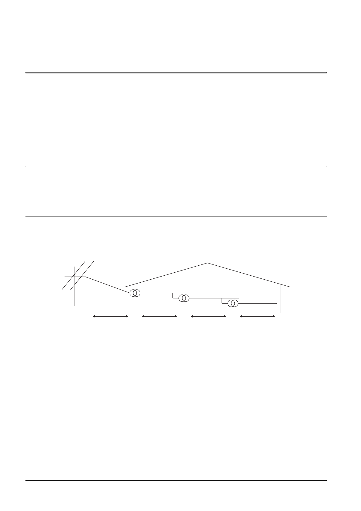
5.2 Requirements for Conpliance with the Low
Voltage Directive
The Low Voltage Directive requires each device which operates with power supply ranging from 50VAC to
1000V and 75VDC to 1500V to satisfy necessary safety items.
In the Sections from 5.2.1 to 5.2.5, cautions on installation and wiring of the GOT to conform to the Low
Voltage Directive requires are described.
We have put the maximum effort to develop this material based on the requirements and standards of the
Directive that we have collected.
However, compatibility of the devices which are fabricated according to the contents of this manual to the
above Directive is not guaranteed. Each manufacturer who fabricates such device should make the final
judgement about the application method of the Low Voltage Directive and the product compatibility.
5.2.1 Standard subject to GOT
Standard applied to GOT: EN61131-2 Programmable controllers - Equipment requirements and tests
EN60950-1 Safety of Information Technology Equipment
5.2.2 Power supply
The insulation specification of the GOT was designed assuming installation category II. Be sure to use the
installation category II power supply to the GOT.
The installation category indicates the durability level against surge voltage generated by lightning strike.
Category I has the lowest durability; category IV has the highest durability.
Category ICategory IICategory IIICategory IV
Installation Category
Category II indicates a power supply whose voltage has been reduced by two or more levels of isolating
transformers from the public power distribution.
5 - 6
5.2 Requirements for Conpliance with the Low Voltage Directive
5.2.1 Standard subject to GOT
Page 83
5.2.3 Control panel
Because the GOT is open type equipment (device designed to be stored within another device), be sure to
use it only when installed in a control panel.
1
(1) Shock protection
In order to prevent those who are unfamiliar with power facility, e.g., an operator, from getting a
shock, make sure to take the following measures on the control panel.
(a) Store the GOT within the control panel locked, and allow only those who are familiar with
power facility to unlock the panel.
(b) Build the structure in order that the power supply will be shut off when the control panel is
opened.
(2) Dustproof and waterproof features
The control panel also provides protection from dust, water and other substances. Insufficient
ingression protection may lower the insulation withstand voltage, resulting in insulation destruction.
The insulation in the GOT is designed to cope with the pollution level 2, so use in an environment
with pollustion level 2 or better.
Pollution level1 : An environment where the air is dry and conductive dust does not exist.
Pollution level2 : An environment where conductive dust does not usually exist, but occasional
temporary conductivity occurs due to the accumulated dust.
Generally, this is the level for inside the control panel equivalent a control room
or on the floor of a typical factory.
Pollution level3 : An environment where conductive dust exits and conductivity may be
generated due to the accumulated dust.
An environment for a typical factory floor.
Pollution level4 : Continuous conductivity may occur due to rain, snow, etc. An outdoor
environment.
OVERVIEW
2
SYSTEM
CONFIGURATION
3
SPECIFICATIONS
4
PART NAME AND
SETTINGS
5
5.2.4 Grounding
The following are applicable ground terminals.Use them in the grounded state.
Be sure to ground the GOT for ensuring the safety and complying with the EMC Directive.
Protective grounding : Ensures the safety of the GOT and improves the noise resistance.
Functional grounding : Improves the noise resistance.
5.2 Requirements for Conpliance with the Low Voltage Directive
5.2.3 Control panel
5 - 7
EMC AND LOW
VOLTAGE
6
INSTALLATION
7
WIRING
8
OPTION
DIRECTIVE
Page 84
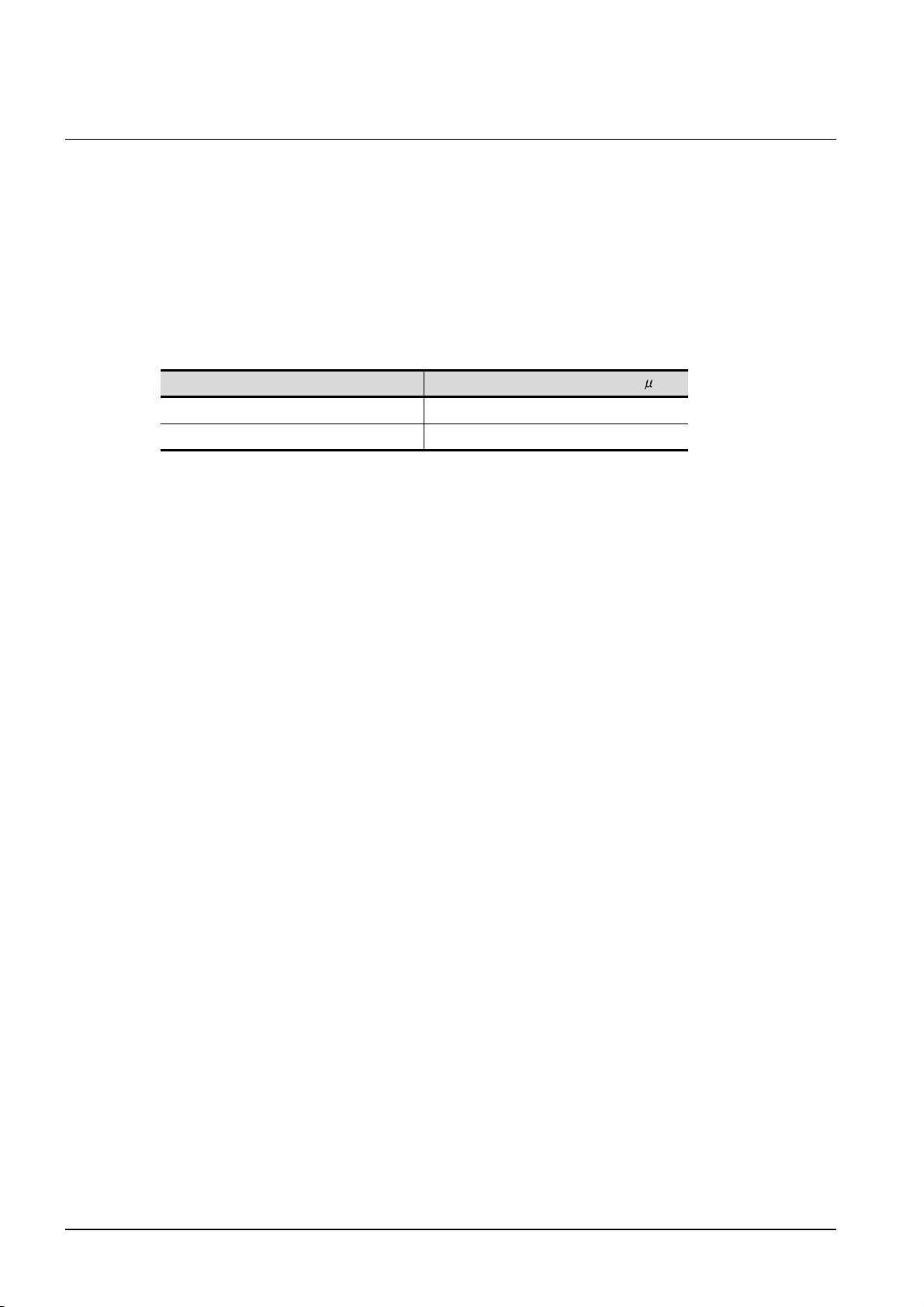
5.2.5 External wiring
(1) External devices
When a device with a hazardous voltage circuit is externally connected to the GOT, select a model
which complies with the Low Voltage Directive's requirements for isolation between the primary and
secondary circuits.
(2) Insulation requirements
Dielectric withstand voltages are shown in the following table.
Reinforced Insulation Withstand Voltage
(Installation Category II, source : IEC664)
Rated voltage of hazardous voltage area
150 VAC or below 2500V
300 VAC or below 4000V
Surge withstand voltage (1.2/50 s)
5 - 8
5.2 Requirements for Conpliance with the Low Voltage Directive
5.2.5 External wiring
Page 85
5.3 EMC Directive-Compliant System Configuration
The information of the EMC Directive-compliant models is obtained from the information site for Mitsubishi
industrial automation products MELFANSweb homepage (MELFANSweb website: http://
wwwf2.mitsubishielectric.co.jp/english/index.html).
1
OVERVIEW
5.3.1 GOT
Use any of the following GOTs with which CE mark logo is printed on the rating plate.
For how to confirm the hardware version of a GOT, refer to the following.
Appendix.2 Confirming of Versions and Conformed Standards
When using a GOT other than shown below, the system does not conform to the EMC Directive.
Hardware version of the GOT
(Production year and month)
GT1595
GT1585
GT1 57
Item Model
GT1595-XTBA Version B or later (Jan., 2006)
GT1595-XTBD Version B or later (Jun., 2006)
GT1585V-STBA Version K or later (Feb., 2007)
GT1585V-STBD Version G or later (Feb., 2007)
GT1585-STBA Version C or later (Apr., 2005)
GT1585-STBD Version B or later (Jan., 2006)
GT1575V-STBA Version J or later (Feb., 2007)
GT1575V-STBD Version G or later (Feb., 2007)
GT1575-STBA Version C or later (May, 2005)
GT1575-STBD Version B or later (Jan., 2006)
GT1575-VTBA Version E or later (May, 2005)
GT1575-VTBD Version B or later (Jan., 2006)
GT1575-VNBA Version K or later (Jan., 2006)
GT1575-VNBD Version B or later (Mar., 2006)
GT1572-VNBA Version K or later (Jan., 2006)
GT1572-VNBD Version B or later (Jan., 2006)
GT1565-VTBA Version E or later (Apr., 2005)
EMC AND LOW
2
SYSTEM
CONFIGURATION
3
SPECIFICATIONS
4
PART NAME AND
SETTINGS
5
VOLTAGE
6
DIRECTIVE
GT1 56
GT1 55
GT1565-VTBD Version B or later (Nov., 2005)
GT1562-VNBA Version J or later (Nov., 2005)
GT1562-VNBD Version B or later (Mar., 2006)
GT1555-QTBD Version F or later (Dec., 2006)
GT1555-QSBD Version F or later (Dec., 2006)
GT1550-QLBD Version F or later (Dec., 2006)
5.3 EMC Directive-Compliant System Configuration
5.3.1 GOT
INSTALLATION
7
WIRING
8
OPTION
5 - 9
Page 86
5.3.2 Connection method
Use the following methods to connect with the GOT to ensure compliance with the EMC Directive.
: Compliant with EMC Directive
Connection method GT1 5
Bus connection
Direct connection to CPU
Computer link connection
MELSECNET/H connection (PLC to PLC network)
MELSECNET/10 connection (PLC to PLC network)
CC-Link connection (intelligent device station)
CC-Link connection (via G4)
Ethernet connection
: Not compliant with EMC Directive
Other connections
*1: For details about each connection method, refer to the GOT1000 Series Connection Manual.
*2: When connecting the GOT to other controllers as a PLC manufactured by other company, create the cable (by
the user) and configure the system to meet the EMC Directive specifications for the connected device.
( 5.4.2 (8)PLC (manufactured by other company), microcomputer, temperature controller, inverter, servo
amplifier or CNC connection)
*2
Connected devices
If connecting to the PLC or microcomputer other than Mitsubishi products
(MELSEC-Q series, MELSEC-QnA series or MELSEC-A series) please refer to the
EMC Directive compliance manual for that specific device.
5 - 10
5.3 EMC Directive-Compliant System Configuration
5.3.2 Connection method
Page 87
5.3.3 When the communication unit is used
Use the following communication unit with the GOT to ensure compliance with the EMC Directive.
The GOT does not comply with the EMC Directive when connected with other than followings.
1
Connection method Communication unit used
GT15-QBUS
GT15-QBUS2
GT15-ABUS
Bus connection
Direct connection to CPU
Computer link connection
MELSECNET/H
connection (PLC to PLC
network)
MELSECNET/10
connection (PLC to PLC
network)
CC-Link connection
(Intelligent device station)
Ethernet connection GT15-J71E71-100
GT15-ABUS2
GT15-75QBUSL
GT15-75QBUS2L
GT15-75ABUSL
GT15-75ABUS2L
GOT RS-232 interface -
GT15-RS2T4-9P Version A or later
GT15-RS2-9P
GT15-RS4-9S
GOT RS-232 interface -
GT15-RS2T4-9P Version A or later
GT15-RS2-9P
GT15-RS4-9S
GT15-J71LP23-25
GT15-J71BR13
GT15-J61BT13
Hardware version of the communication unit
(Production year and month)
Version D or later
(Oct., 2005)
Version C or later
(Oct., 2005)
Version G or later
(Mar., 2005)
Version D or later
(Jan., 2006)
Version D or later
(Jan., 2006)
Version C or later
(Sep., 2006)
Version C or later
(Sep., 2006)
Version B or later
(Mar., 2005)
EMC AND LOW
OVERVIEW
2
SYSTEM
CONFIGURATION
3
SPECIFICATIONS
4
PART NAME AND
SETTINGS
5
VOLTAGE
6
DIRECTIVE
Microcomputer connection
Third party PLC
connection
GOT RS-232 interface -
GT15-RS2T4-9P Version A or later
GT15-RS2-9P
GT15-RS4-9S
GOT RS-232 interface -
GT15-RS2T4-9P Version A or later
GT15-RS2-9P
GT15-RS4-9S
5.3 EMC Directive-Compliant System Configuration
Version D or later
(Jan., 2006)
Version D or later
(Jan., 2006)
5.3.3 When the communication unit is used
(Continued to next page)
5 - 11
INSTALLATION
7
WIRING
8
OPTION
Page 88
Connection method Communication unit used
GOT RS-232 interface -
GT15-RS2T4-9P Version A or later
Temperature controller
Inverter connection
Servo amplifier
connection
CNC connection
GT15-RS2-9P
GT15-RS4-9S
GT15-RS4-TE
GT15-RS2T4-9P Version A or later
GT15-RS4-9S
GOT RS-232 interface -
GT15-RS2T4-9P Version A or later
GT15-RS2-9P
GT15-RS4-9S
GOT RS-232 interface -
GT15-RS2T4-9P Version A or later
GT15-RS2-9P
GT15-RS4-9S
GT15-J71LP23-25
GT15-J71BR13
GT15-J61BT13
Hardware version of the communication unit
(Production year and month)
Version D or later
(Jan., 2006)
Version D or later
(Jan., 2006)
Version D or later
(Jan., 2006)
Version D or later
(Jan., 2006)
Version C or later
(Sep., 2006)
GT15-J71E71-100
Version B or later
(Mar., 2005)
The GOT does not comply with the EMC Directive when it is used with the following unit.
Product name Model name
MELSECNET/10 communication unit GT15-75J71LP23-Z, GT15-75J71BR13-Z
CC-Link communication unit G15-75J61BT13-Z
5 - 12
5.3 EMC Directive-Compliant System Configuration
5.3.3 When the communication unit is used
Page 89
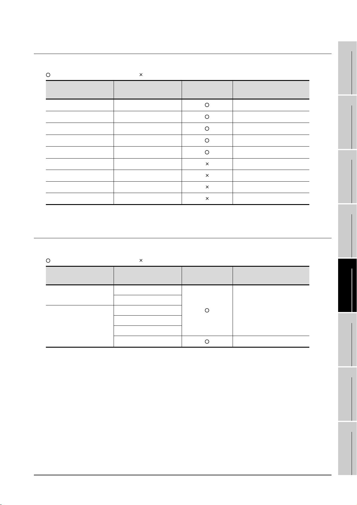
5.3.4 When the option unit is used
The following shows EMC Directive compliance of option units.
: Compliant with EMC Directive : Not compliant with EMC Directive
1
Product name Model name EMC Directive
Printer unit* GT15-PRN Version B or later (Feb.,2006)
Video input unit GT15V-75V4R1 Version D or later (Feb.,2007)
RGB input unit GT15V-75V4 Version D or later (Feb.,2007)
Video/RGB input unit GT15V-75R1 Version D or later (Feb.,2007)
RGB output unit GT15V-75ROUT Version C or later (Feb.,2007)
CF card unit GT15-CFCD -
CF card extension unit GT15-CFEX-C08SET -
External I/O unit GT15-DIO -
Sound output unit GT15-SOUT -
*: For the printer to be connected, configure the system in accordance with the EMC Directive specifications for the
printer as requested by the printer manufacturer.
Hardware version
(Production year and month)
5.3.5 When the option is used
The following shows EMC Directive compliance of option.
: Compliant with EMC Directive : Not compliant with EMC Directive
Product name Model name EMC Directive
Option function board
Option function board with
add-on memory
GT15-FNB
GT15-QFNB
GT15-QFNB16M
GT15-QFNB32M
GT15-QFNB48M
Hardware version
(Production year and month)
Version A or later (Mar.,2005)
EMC AND LOW
OVERVIEW
2
SYSTEM
CONFIGURATION
3
SPECIFICATIONS
4
PART NAME AND
SETTINGS
5
VOLTAGE
6
DIRECTIVE
GT15-MESB48M Version C or later (Jun.,2006)
5.3 EMC Directive-Compliant System Configuration
5.3.4 When the option unit is used
INSTALLATION
7
WIRING
8
OPTION
5 - 13
Page 90

5.3.6 Cables
(1) Cables used
(a) For the MELSECNET/H connection (coaxial cable), MELSECNET/10 connection (coaxial
cable), and video connection, use double shield coaxial cables.
For double shield coaxial cables, refer to the following manuals.
GT15 MELSECNET/H communication unit User's Manual
MODEL GT15V-75V4R1 Video/RGB Input Unit MODEL GT15V-75V4 Video Input Unit MODEL
GT15V-75R1 RGB Input Unit User's Manual
(b) For details of the cables used for conncetions other than the above, refer to the GOT1000
Series Connection Manual.
(2) Adjusting a cable for the EMC Directive compliance
Modify the cables (including user-produced cable) to ensure compliance with the EMC Directive.
For details, refer to Section 5.4.2.
5 - 14
5.3 EMC Directive-Compliant System Configuration
5.3.6 Cables
Page 91
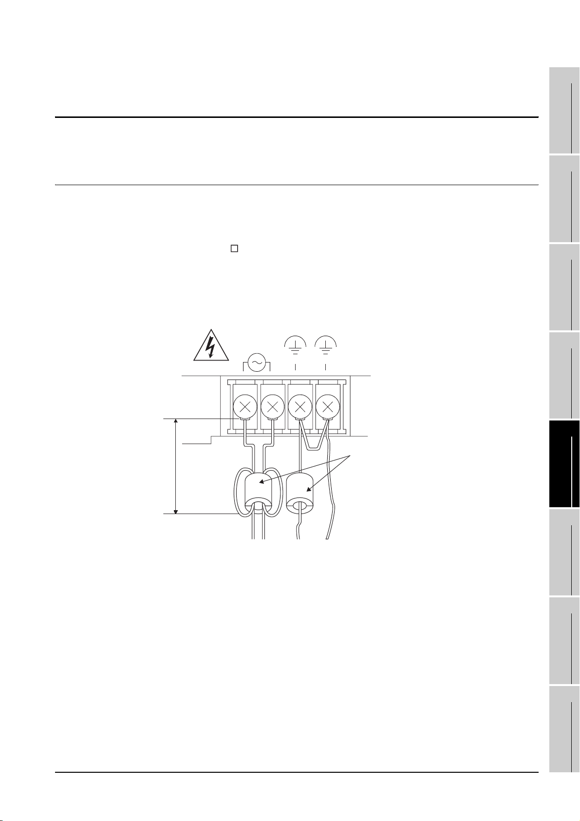
5.4 Precautions for Wiring/Connecting the EMC
Directive-Compliant Product
1
Wire and connect GOT1000 series equipments as instructed below. If the GOT1000 series equipments are
configured in a way different from the following instructions, the system may not comply with EMC directives.
5.4.1 Power and ground wires wiring method
(1) Power and ground wires wiring method
Connect the power wire and connection cable as shown in the illustration, and be sure to attach a
ferrite core (TDK Corporation type ZCAT3035-1330) within the range shown below. (Ferrite cores
are not required for GT155 .)
Lead the power wire and ground wire as shown in Section 5.1.2 (2).
Be sure to ground the LG cable, FG cable, and protective ground cable.
(a) 100-240VAC GOT power section
• Video/RGB connection
GOT power supply section
INPUT
100-240VAC
(LG) (FG)
OVERVIEW
2
SYSTEM
CONFIGURATION
3
SPECIFICATIONS
4
PART NAME AND
SETTINGS
90mm or less
Ferrite core
(ZCAT3035-1330)
EMC AND LOW
5
VOLTAGE
6
INSTALLATION
7
WIRING
8
DIRECTIVE
5.4 Precautions for Wiring/Connecting the EMC Directive-Compliant Product
OPTION
5 - 15
Page 92
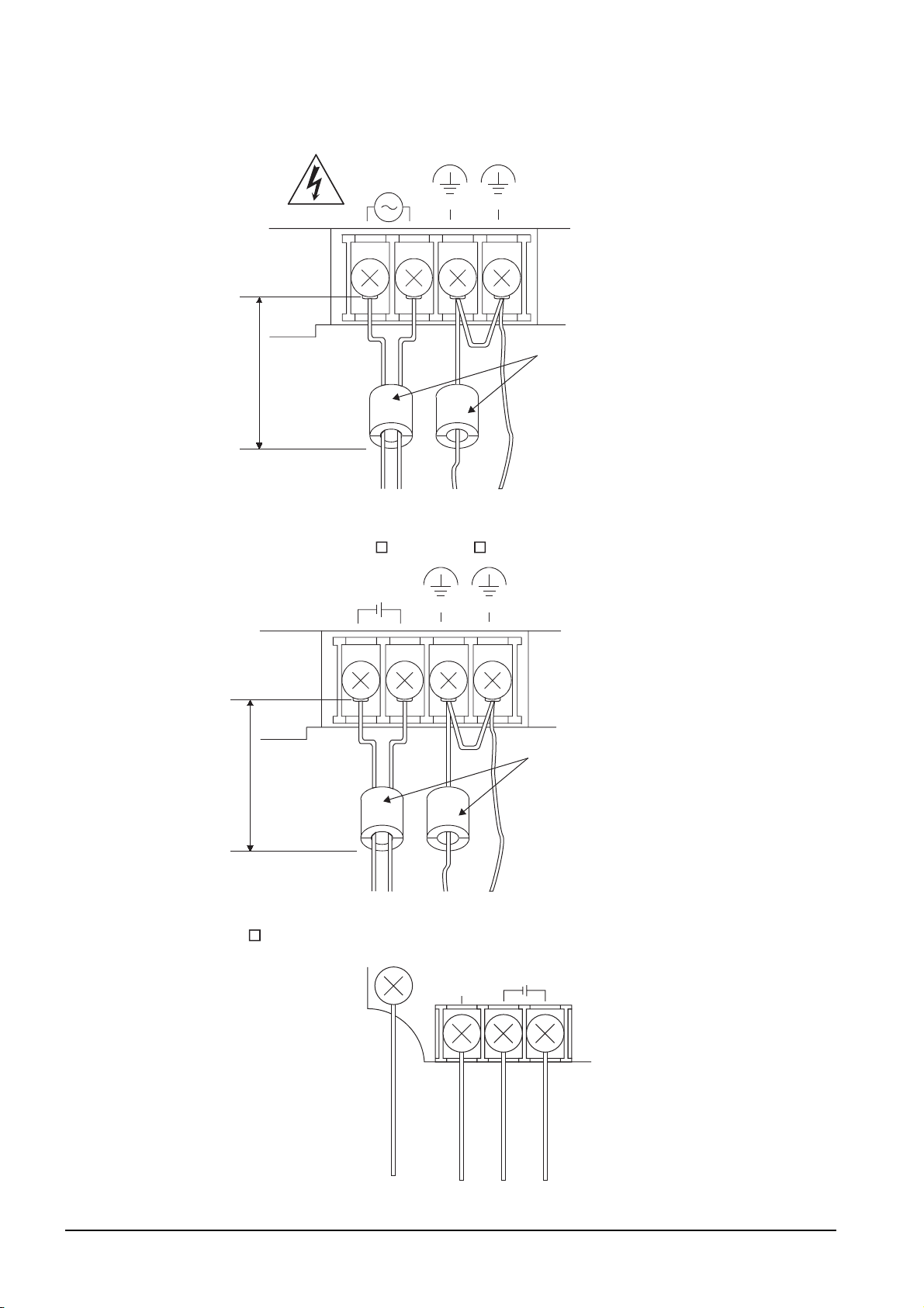
• Connections other than above
GOT power supply section
INPUT
100-240VAC
90mm or less
(b) 24VDC GOT power section
• GT1595, GT1585, GT157 , and GT156
(LG) (FG)
Ferrite core
(ZCAT3035-1330)
•GT155
90mm or less
INPUT
24VDC
Protective grounding
(LG) (FG)
(FG)
Ferrite core
(ZCAT3035-1330)
INPUT
24VDC
+-
5 - 16
* Be sure to ground the protective ground terminal and the FG terminal respectively.
5.4 Precautions for Wiring/Connecting the EMC Directive-Compliant
Product
Page 93
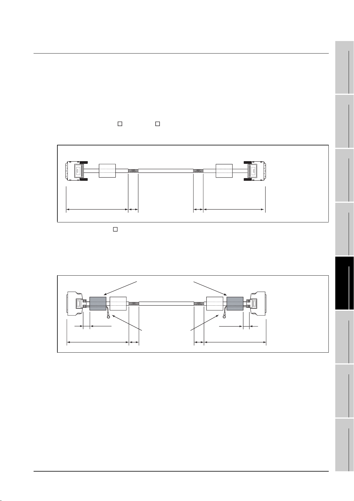
5.4.2 Processing connection cables
(
)
(
)
Process the cable used with the GOT with the following method.
When processing the cable, ferrite core, cable clamp and shielding material are required.
The cable clamp used by Mitsubishi Electric for the EMC specification compatibility test is shown below.
• TDK corporation brand ZCAT3035-1330 Ferrite Core
• Mitsubishi Electric Model AD75CK cable clamp
• Japan Zipper Tubing Co., Ltd. Zipper tube SHNJ type
(1) BUS connection cable
(a) For GT15-QC B, GT15-QC BS
• Peel the sheath (with the length shown below) at both ends of the cable, and expose the
shield braided wire for grounding. (For grounding with cable clamps. (refer to Section 5.4.3.))
GOT side
360 or less
(14.17)
40 40
(1.57)(1.57)
360 or less
(14.17)
PLC/GOT side
Unit : mm (inch)
1
2
SYSTEM
3
4
OVERVIEW
CONFIGURATION
SPECIFICATIONS
(b) For GT15-C BS
• Cut the connection wire protruding from both ends of the cable to the lengths shown below.
• Attach the ferrite core to the cable in the position as illustrated below and insert the ground
wire into the ferrite core.
• Peel the sheath (with the length shown below) at both ends of the cable, and expose the
shield braided wire for grounding. (For grounding with cable clamps. (refer to Section 5.4.3.))
GOT side
60 or less
(2.36)
360 or less
(14.17)
Ferrite Core
(ZCAT3035-1330)
Ground wires
(280mm (11.0 inch))
40
1.57
40
1.57
60 or less
(2.36)
360 or less
(14.17)
PLC/GOT side
Unit : mm (inch)
EMC AND LOW
PART NAME AND
SETTINGS
5
VOLTAGE
6
INSTALLATION
7
DIRECTIVE
WIRING
8
OPTION
5.4 Precautions for Wiring/Connecting the EMC Directive-Compliant
Product
5 - 17
Page 94
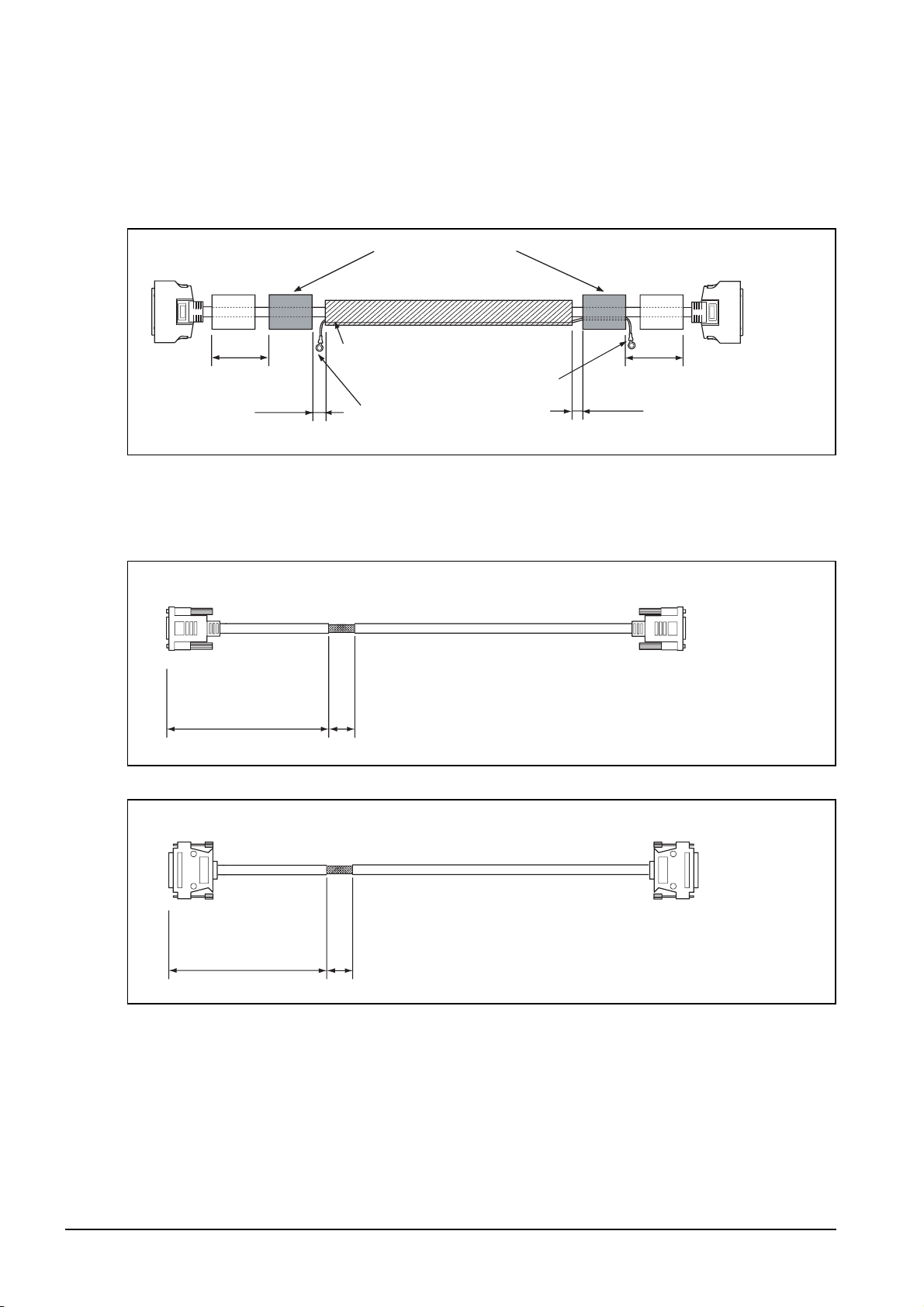
(c) For other bus connection cables
• Wind cable shield material around the cable, and pull out the grounding braided wire of the
cable shield material with the length shown below.
• Attach the ferrite core to the cable in the position as illustrated below and insert the braided
wire for grounding into the ferrite core.
GOT side
80
(3.15)
40 or less
(1.57)
(2) CPU direct connection and computer link connection
• Peel the sheath (with the length shown below) of the cable to expose the shield braided wire for
grounding. (For grounding with cable clamps (refer to Section 5.4.3))
(a) For RS-232 cable
GOT side
Cable shield material
Ferrite Core
(ZCAT3035-1330)
Grounding braided wire
(200mm (7.87 inch))
Grounding braided wire
(50mm (1.97 inch))
(3.15)
40 or less
(1.57)
PLC side
PLC side
80
Unit : mm (inch)
230 or less
(9.06)
(b) RS-422 cable (For AC30/100/300R4-25P)
GOT side
230 or less 40
40
(1.57)
(1.57)
Unit : mm (inch)
PLC side
Unit : mm (inch)(9.06)
5 - 18
5.4 Precautions for Wiring/Connecting the EMC Directive-Compliant
Product
Page 95
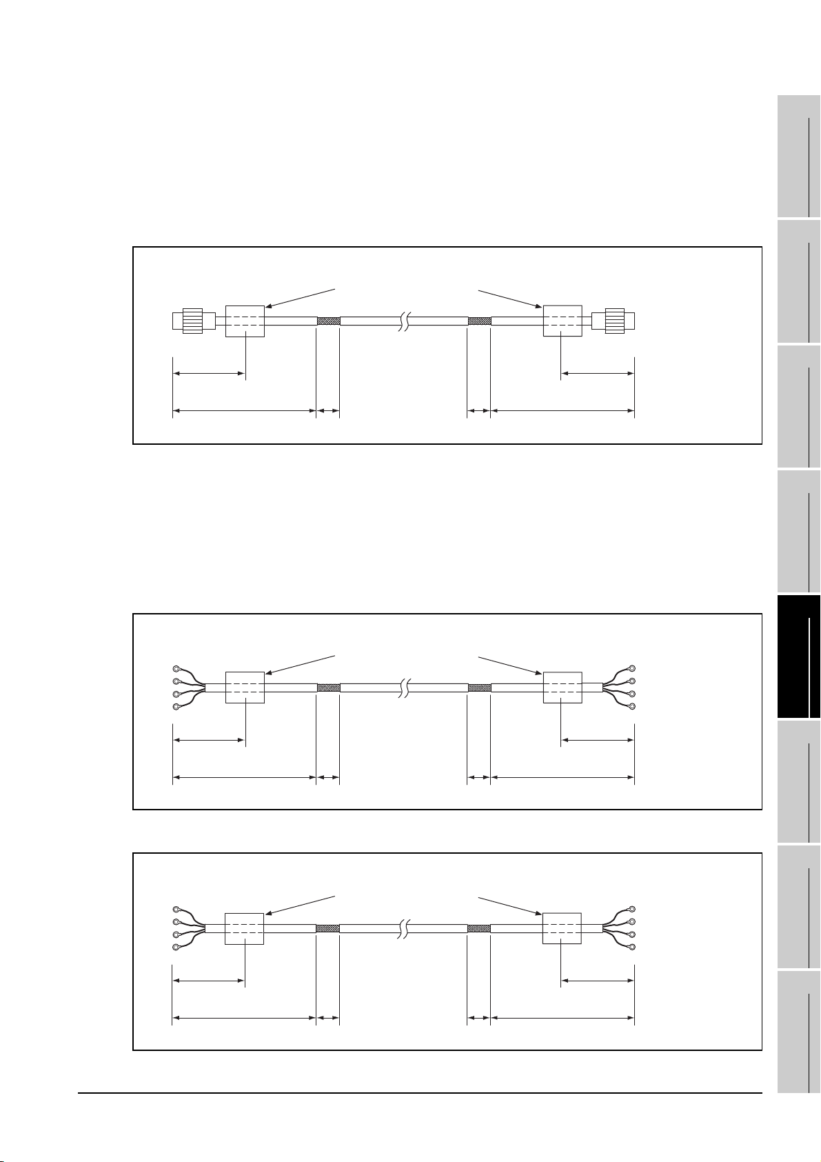
(3) MELSECNET/H connection (PLC to PLC network) and MELSECNET/10 connction (PLC to PLC
network)
(a) For coaxial cable
• Strip the outer insulation layer at both ends of the cable by the length shown below to expose
the outer braided shield for grounding. (For grounding with cable clamps (refer to Section
5.4.3.))
• Attach ferrite cores to the cable in the positions as illustrated below.
1
OVERVIEW
2
GOT side
130 or
less
(5.12) (5.12)
230 or less
(9.06)
(b) For optical fiber cable
• Processing of the cable is not required.
(4) CC-Link connection (Intelligent device station)
Strip the outer insulation layer at both ends of the cable by the length shown below to expose the
braided shield for grounding. (For grounding with cable clamps (refer to Section 4.4.3.))
• Attach ferrite cores to the cable in the positions as illustrated below.
• CC-Link dedicated cable for connecting the GOT and PLC.
GOT side
40
(1.57)
Ferrite Core
(ZCAT3035-1330)
Ferrite Core
(ZCAT3035-1330)
40
(1.57)
130 or
less
400 or less
(15.75)
PLC side
PLC side
Unit : mm (inch)
SYSTEM
CONFIGURATION
3
SPECIFICATIONS
4
PART NAME AND
SETTINGS
5
130
(5.12)
230 or less
(9.06)
• CC-Link dedicated cable for connecting the GOT and GOT
GOT side GOT side
130
(5.12)
230 or less
(9.06)
40
(1.57)
Ferrite Core
(ZCAT3035-1330)
40
(1.57)
5.4 Precautions for Wiring/Connecting the EMC Directive-Compliant
40
(1.57)
40
(1.57)
400 or less
(15.75)
230 or less
(9.06)
130
(5.12)
130
(5.12)
Unit : mm (inch)
Unit : mm (inch)
Product
5 - 19
EMC AND LOW
VOLTAGE
6
INSTALLATION
7
WIRING
8
OPTION
DIRECTIVE
Page 96
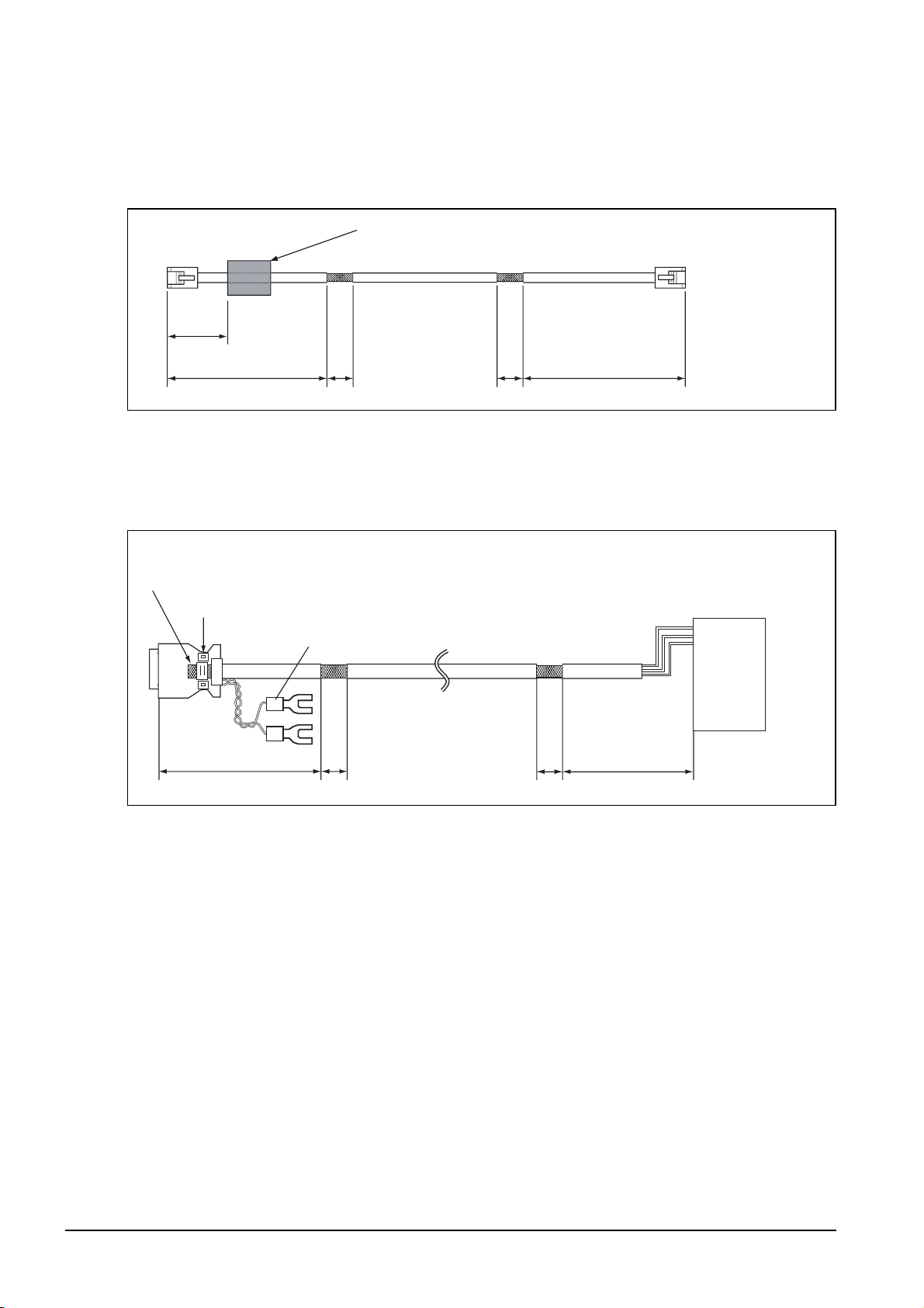
(5) Ethernet connection
• Strip the outer insulation layer at both ends of the cable by the length shown below to expose the
braided shield for grounding. (For grounding with cable clamps. (refer to Section 5.4.3.))
• Attach the ferrite core to the cable in the position as illustrated below.
GOT side
120 or
less
(4.72)
230 or less
(9.06)
(6) External I/O device connection
• Strip the outer insulation layer at both ends of the cable by the length shown below to expose the
braided shield for grounding.(For grounding with cable clamps (Refer to Section 5.4.3.))
• Connect the braided shield to the connector with the connector cover.
• Twist power cables.
GOT side External I/O device side
Braided shield
Connector cover
Power cable
Ferrite Core
(ZCAT3035-1330)
40
(1.57)
40
(1.57)
400 or less
(15.75)
PLC side
Unit : mm (inch)
360 or less 360 or less40 40
(14.17) (14.17)
(1.57) (1.57)
Unit : mm (inch)
5 - 20
5.4 Precautions for Wiring/Connecting the EMC Directive-Compliant
Product
Page 97
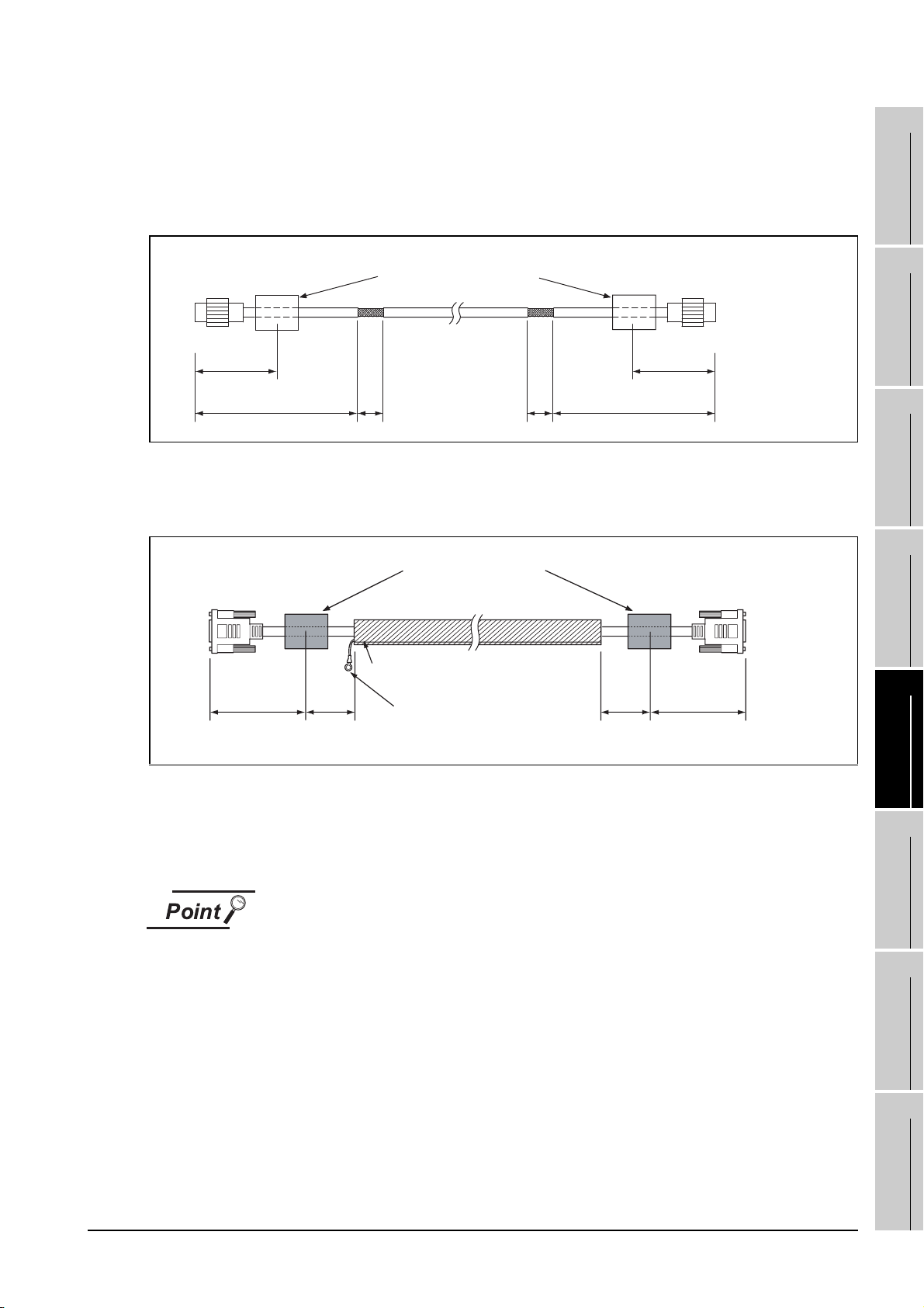
(7) Video/RGB connection
(a) Video input
• Peel the sheath (with the length shown below) at both ends of the cable, and expose the
shield braided wire for grounding. (For grounding with cable clamps. (refer to Section 5.4.3.))
• Attach the ferrite core to the cable in the position as illustrated below.
1
OVERVIEW
GOT side
130 or
less
(5.12) (5.12)
230 or less
(9.06)
(b) RGB input/output
• Wind cable shield material around the cable, and pull out the grounding braided wire of the
cable shield material with the length shown below.
• Attach the ferrite core to the cable in the position as illustrated below.
GOT side
40
130 or less
(5.12) (1.57)
or less
40
(1.57)
Ferrite Core
(ZCAT3035-1330)
Ferrite Core
(ZCAT3035-1330)
Cable shield material
Grounding braided wire
(50mm)
40
(1.57)
400 or less
(15.75)
40
or less
Camcorder/vision
sensor side
130 or
less
Unit : mm (inch)
Vision sensor/
personal computer/
external display side
130 or less
(5.12)(1.57)
Unit : mm (inch)
2
SYSTEM
CONFIGURATION
3
SPECIFICATIONS
4
PART NAME AND
SETTINGS
5
(8) PLC (manufactured by other company), microcomputer, temperature controller, inverter, servo
amplifier or CNC connection
Produce the cable (RS-232 cable, RS-422 / 485 cable) for connecting the GOT to a controller with
reference to the GOT1000 Series Connection Manual.
Configure the system to meet the EMC Directive specifications for the connected
device when connecting the GOT to a controller.
The following gives the instructions to ensure the machinery comply with the EMC
Directive. However, the manufacturer of the machinery must finally determine how
to make it comply with the EMC Directives: if it is actually compliant with the EMC
Directives.
5.4 Precautions for Wiring/Connecting the EMC Directive-Compliant
Product
5 - 21
EMC AND LOW
VOLTAGE
6
INSTALLATION
7
WIRING
8
OPTION
DIRECTIVE
Page 98
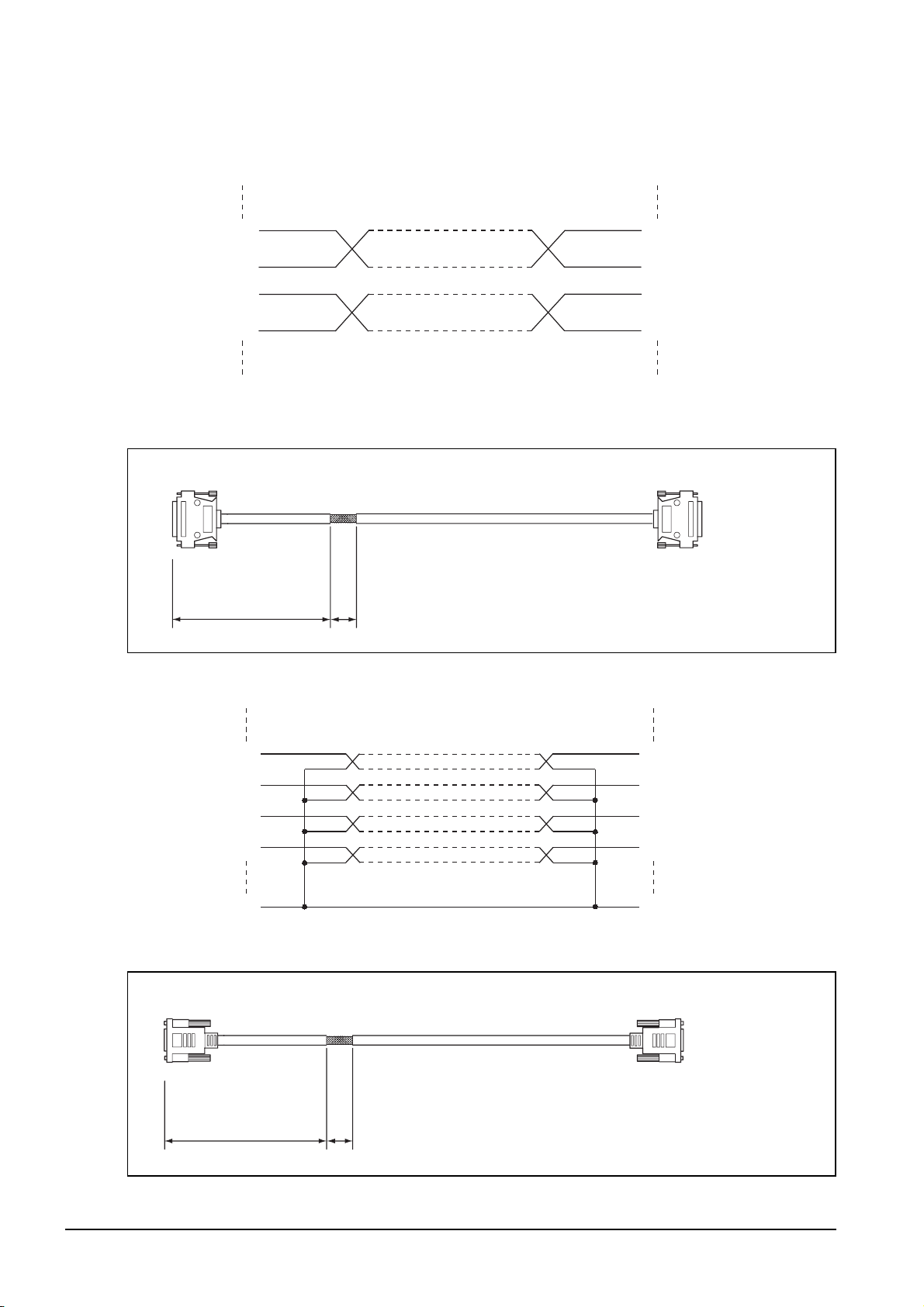
(a) For RS-422 / 485 cable
• Each signal wire (excluding SG and FG) should be made into a two power wires and
connected, then twisted.
SDA
SDB
RDA
RDB
• Make the SG wire more than two wires and connect.
• Peel the sheath (with the length shown below) of the created cable to expose the shield
braided wire for grounding. (For grounding with cable clamps (refer to Section 5.4.3))
GOT side
230 or less 40
(1.57)
(b) For RS-232 cable
• Use a twisted pair style for each signal wire (except SG, FG) with SG.
RDA
RDB
SDA
SDB
PLC side
Unit : mm (inch)(9.06)
RD
SD
DTR
DSR
SG
• Peel the sheath (with the length shown below) of the created cable to expose the shield
braided wire for grounding. (For grounding with cable clamps (refer to Section 5.4.3))
GOT side
230 or less 40
(1.57)
SD
RD
DSR
DTR
SG
PLC side
Unit : mm (inch)(9.06)
5 - 22
5.4 Precautions for Wiring/Connecting the EMC Directive-Compliant
Product
Page 99
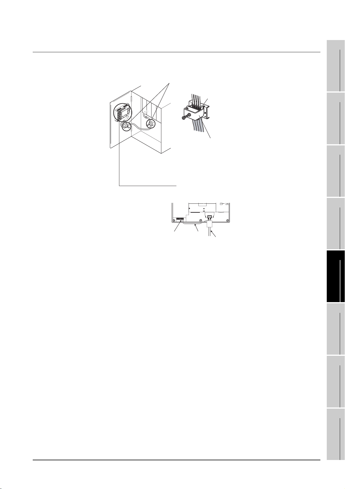
5.4.3 Grounding the cable
Ground the cable and grounding wire to the control panel where the GOT and base unit are installed.
1) Ground the braided shield portion
of the cable to the control panel
with the cable clamp (AD75CK).
Braided shield
Cable clamps
For the cable clamp attaching
details, refer to AD75CK-type Cable
Clamping Instruction Manual <IB68682>.
a) For GT15-C EXSS-1 and
GT15-C BS
Ground the ground wire to the
FG terminal of the GOT power
supply section.
1
2
SYSTEM
3
4
OVERVIEW
CONFIGURATION
SPECIFICATIONS
GOT FG terminal FG wire
b) For other bus connection
cables
Ground the braided wire for
grounding to the control panel
by tightening a screw.
Bus connection cable
EMC AND LOW
PART NAME AND
SETTINGS
5
VOLTAGE
6
INSTALLATION
7
DIRECTIVE
5.4 Precautions for Wiring/Connecting the EMC Directive-Compliant
Product
WIRING
8
OPTION
5 - 23
Page 100
6. INSTALLATION
CAUTION
Use the GOT in the environment that satisfies the general specifications described in this manual.
Do not expose the GOT to dust, lamp soot, conductive dust, corrosive gas, or combustible gas;
high-temperature, condensing, wind or rain; or to vibrations and impact.
Failure to do so can cause an electric shock, fire, malfunction or product damage or deterioration.
Do not drop chips or wire scraps near the ventilation window of the GOT when processing screw
holes or wiring.
Failure to do so can cause a fire, failure or malfunction.
Tighten the mounting screws within the specified torque range.
Undertightening can cause the GOT to drop, short circuit or malfunction.
Overtightening can cause a drop, short-circuit or malfunction due to the damage of the screws or
the unit.
Make sure to install the connection cable to the connector specified during the power OFF.
Failure to do so may cause a malfunction due to the poor contact.
6.1 Control Panel Inside Dimensions for Mounting
GOT
Install the GOT and the CF card extension unit on the control panel out of the way for the equipment inside
the control panel. Do not install the GOT and the unit in prohibited areas for the installation.
Applicable cable
Some cables may need to be longer than the specified dimensions when connecting
to the GOT.
Therefore, consider the connector dimensions and bending radius of the cable as
well for installation.
6 - 1
6.1 Control Panel Inside Dimensions for Mounting GOT
 Loading...