

MITSMI MM1177AF, MM1177BF Datasheet
MITSUMI
Charge and discharge control for coin-type lithium batteries and manganese dioxide lithium batteries MM1177
Charge and discharge control for coin-type lithium batteries and
manganese dioxide lithium batteries
Monolithic IC MM1177
Outline
This IC controls constant current charging and excess discharge for coin-shaped vanadium lithium batteries
and manganese dioxide batteries. It performs constant current charging, stops charging at set voltages, and
prevents excess discharging. When the voltage falls bellow a set level, it prohibits discharges and reduces IC
current consumption nearly to zero.
Features
During charging
1. Input voltage range 4.0~15.0V
2. Current consumption (during constant current charging) 100µA typ.
3. Current consumption (when charging is off) 30µA typ.
4. Charging current 4.5mA typ.
5. Charging shut-off voltage (Ta=
During discharging
1. Discharging shut-off voltage 1.75V±0.15V
2. Current consumption (I
3. Leak current during discharge shut-off 0.1µA max.
4. Voltage drop between battery and output (I
L
-
20~+70°C) 1177AF : 3.275V±75mV
1177BF : 3.0V±70mV
-
100µA, VBATT=3V) 5µA typ.
L=100µA, VBATT=3V) 2.92V typ.
Package
SOP-8C (MM1177AF, MM1177BF)
Applications
1. coin-shaped vanadium lithium batteries
2. Monitors and controls charging and discharging for and manganese dioxide batteries.
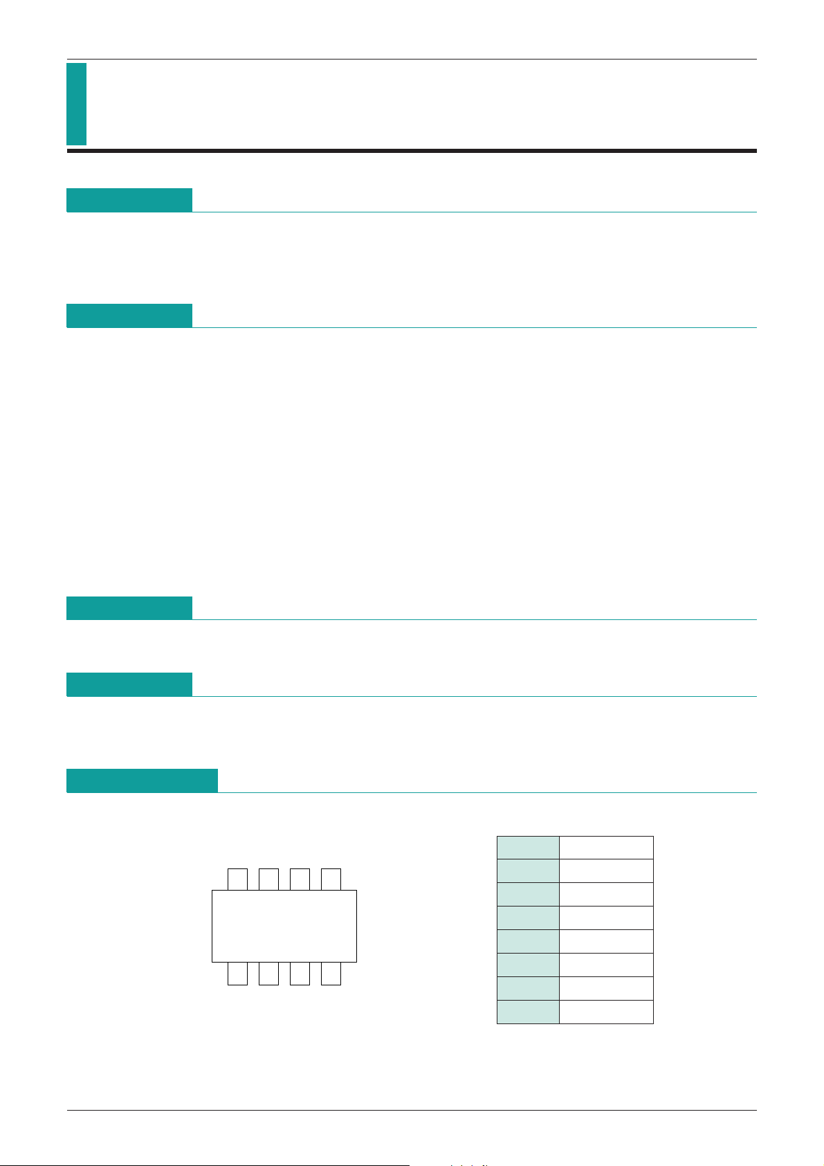
Pin Assignment
1 N.C
2 GND
8567
1432
SOP-8C
3 NC
4 OUT2
5 OUT1
6 BATT
7 N.C
8 V
IN

MITSUMI
Charge and discharge control for coin-type lithium batteries and manganese dioxide lithium batteries MM1177
Block Diagram
Absolute Maximum Ratings
Item Symbol Rating Units
Storage temperature T
Operating temperature T
input voltage V
Charging voltage V
Allowable power dissipation P
Charging current I
Discharging current I
Electrical Characteristics
Item Symbol Measurement Conditions Min Typ. Max. Units
Input voltage operation range V
Current consumption 1 I
Current consumption 2 I
Charging current (limiter current)
Limiter mode off
1177AF
1177BF 2.70
STG
OPR
IN max. 18 V
BAT max. 3.5 V
D 300 mW
BATT 10 mA
L 1mA
-
40~+125 °C
-
20~+70 °C
(Unless otherwise specified Ta=25°C, VIN=12.0V)
INOPR 4.0 15.0 V
IN1
IN2 charging off 30 45 µA
during charging (constant voltage charge)
100 180 µA
IBATT VIN=4V~15V, VBATT=2V 4.0 4.5 5.0 mA
3.00
ICOFF IBATT=4mA
V
V
Charging OFF voltage
1177AF
CHOFF IBATT=0mA, Ta=
V
-
20~+70°C
3.20 3.275 3.35 V
1177BF 2.93 3.00 3.07 V
Current consumption (battery) I
Leak current when discharging
is prohibited
Voltage when discharging is prohibited
Voltage drop between battery
and output
OUT2 pin voltage V
BA1IL=100µA, VBATT=3V 5 8 µA
V
IN=0V or open
IBA2
VBATT=3.35V
VOOFF after VIN=0FF 1.60 1.75 1.90 V
CEOUT IL=100µA, VBATT=3V 75 100 mV
V
OUT2VCELL=3V 2.85 2.92 3.00 V
Note : Do not connect the OUT2 pin to the load; it does not have current supply capability.
To delay discharge prohibition, or suppress discharge prohibition caused by noise, connect a capacitor
between the OUT2 pin and GND.
0.1 µA
 Loading...