

MITSMI MM1135XF, MM1136XF Datasheet
Model VSLB VSLR TPR TWD TWR
MM1135 100mS 10mS 2mS
MM1136
3.4V 3.2V
100mS 100mS 2mS
MITSUMI
System Reset (with built-in watchdog timer) MM1135, MM1136
System Reset (with built-in watchdog timer)
Monolithic IC MM1135, MM1136
Outline
These ICs were developed to drive low voltage batteries, and have a watchdog timer with built-in
microcomputer reset voltage detection circuit and low battery detection circuit.
A single reference voltage is used for low battery voltage detection and microcomputer reset voltage
detection, so detection voltage difference is uniform (.=.0.2V). Further, there is a built-in watchdog timer for
operation diagnosis, which prevents the system from running wild by generating an intermittent reset pulse
during system mis-operation.
Features
1. Accurate voltage drop detection voltage
1. Low battery detection 3.4V±3%
2. Power supply voltage detection 3.2V±3%
3. Detection voltage error 0.2V±20mV 1-2
4. Hysteresis Both 50mV typ.
2. Watchdog function stop pin (can be made to function only as reset IC during V
CC rise)
3. Low current consumption 150µA typ.
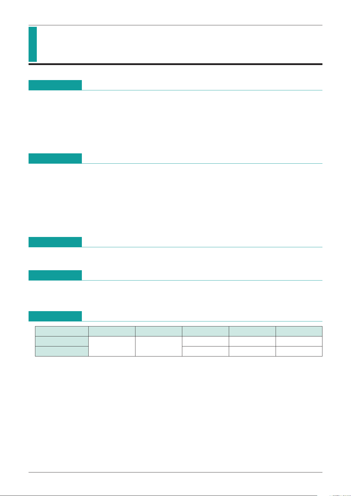
Package
SOP-8C (MM1135XF, MM1136XF)
Series Table
Applications
1. 3V cordless telephones
2. Various types of small, handy equipment
*
CT=0.02µF
T
PR : Reset hold time during VCC rise
T
WD : Timer monitoring time
T
WR : Reset time
V
SLB : Battery check detection voltage
V
SLR : Reset detection voltage
MITSUMI
System Reset (with built-in watchdog timer) MM1135, MM1136
Pin Assignment
1432
8567
SOP-8C
1 TC
2
BC (RESET
----------------------------------------------------------------------------------------
)
3 CK
4 GND
5 V
CC
6 RCT
7 V
S
8
RESET
----------------------------------------------------------------------------------------
Pin Description
Pin No. Pin name Function
1 TC T
WD, TWR, TPR time setting pins.
2 BC (
RESET
----------------------------------------------------------------------------------------
) Battery check output pin (RESET low level output) for 3.4V
3 CK Clock input pin
4 GND GND pin
5 V
CC Power supply voltage input pin
6 RCT
Watchdog timer stop pin
Operation OPEN, Stop connect to GND
7 V
S Detection voltage fine adjustment pin
8
RESET
----------------------------------------------------------------------------------------
Reset output pin (low output)
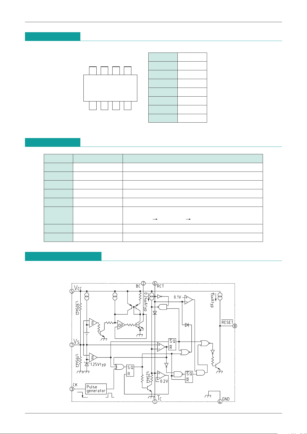
Block Diagram
 Loading...