

Page 1

FXCPU
Structured Programming Manual
Device & Common
Page 2

Page 3
FXCPU Structured Programming Manual
[Device & Common]
FXCPU Structured Programming Manual
[Device & Common]
Manual No. JY997D26001
Revision L
Date 4/2015
Foreword
This manual describes devices and parameters for structured programs used in the MELSEC-F FX Series.
Please read this manual and manuals of relevant products before use, sufficiently understand the
specifications, and use the unit correctly and safely.
See to it that this manual is supplied to the end user.
This manual confers no industrial property rights or any rights of any other kind, nor does it confer any patent licenses.
Mitsubishi Electric Corporation cannot be held responsible for any problems involving industrial property rights which may occur as a
result of using the contents described in this manual.
© 2009 Mitsubishi Electric Corporation
1
Page 4

FXCPU Structured Programming Manual
[Device & Common]
Outline Precautions
• This manual provides information for the use of the FX Series Programmable Controllers. The manual has
been written to be used by trained and competent personnel. The definition of such a person or persons is
as follows;
a) Any engineer who is responsible for the planning, design and construction of automatic equipment
using the product associated with this manual should be of a competent nature, trained and qualified
to the local and national standards required to fulfill that role. These engineers should be fully aware
of all aspects of safety with regards to automated equipment.
b) Any commissioning or service engineer must be of a competent nature, trained and qualified to the
local and national standards required to fulfill that job. These engineers should also be trained in the
use and maintenance of the completed product. This includes being completely familiar with all
associated documentation for the said product. All maintenance should be carried out in accordance
with established safety practices.
c) All operators of the completed equipment should be trained to use that product in a safe and
coordinated manner in compliance to established safety practices. The operators should also be
familiar with documentation which is connected with the actual operation of the completed
equipment.
Note: the term 'completed equipment' refers to a third party constructed device which contains or uses
the product associated with this manual
• This product has been manufactured as a general-purpose part for general industries, and has not been
designed or manufactured to be incorporated in a device or system used in purposes related to human life.
• Before using the product for special purposes such as nuclear power, electric power, aerospace, medicine
or passenger movement vehicles, consult with Mitsubishi Electric.
• This product has been manufactured under strict quality control. However when installing the product
where major accidents or losses could occur if the product fails, install appropriate backup or failsafe
functions in the system.
• When combining this product with other products, please confirm the standard and the code, or regulations
with which the user should follow. Moreover, please confirm the compatibility of this product to the system,
machine, and apparatus with which a user is using.
• If in doubt at any stage during the installation of the product, always consult a professional electrical
engineer who is qualified and trained to the local and national standards. If in doubt about the operation or
use, please consult the nearest Mitsubishi Electric representative
• Since the examples indicated by this manual, technical bulletin, catalog, etc. are used as a reference,
please use it after confirming the function and safety of the equipment and system. Mitsubishi Electric will
accept no responsibility for actual use of the product based on these illustrative examples.
• This manual content, specification etc. may be changed without a notice for improvement.
• The information in this manual has been carefully checked and is believed to be accurate; however, you
have noticed a doubtful point, a doubtful error, etc., please contact the nearest Mitsubishi Electric
representative.
Registration
•Microsoft®, Windows® and Excel® are either registered trademarks or trademarks of Microsoft Corporation
in the United States and/or other countries.
• CompactFlash is a trademark of SanDisk Corporation in the United States and other countries.
• Ethernet is a trademark of Xerox Corporation.
•MODBUS
• The company name and the product name to be described in this manual are the registered trademarks or
trademarks of each company.
2
®
is a registered trademark of Schneider Electric SA.
Page 5

FXCPU Structured Programming Manual
[Device & Common]
Table of Contents
Positioning of This Manual....................................................................................................... 6
Related Manuals........................................................................................................................ 9
Generic Names and Abbreviations Used in Manuals .......................................................... 12
1. Device Outline 13
1.1 Devices Constructing PLC ......................................................................................................... 13
1.1.1 Relation among devices ................................................................................................................ 14
1.1.2 Device function list.........................................................................................................................15
1.2 Program Memory and Devices................................................................................................... 17
1.2.1 Memory structure........................................................................................................................... 17
1.2.2 Memory operations and backup against power interruption (power ON/OFF and RUN/STOP) ... 22
1.2.3 Types of backup methods against power interruption...................................................................32
1.2.4 Change of devices between general type and latched (backed-up) type...................................... 33
1.2.5 How to initialize latched (backed-up) type devices........................................................................ 33
2. Devices in Detail 35
Table of Contents
2.1 Device Number List..................................................................................................................... 35
2.2 Input/Output Relays [X and Y] ................................................................................................... 37
2.2.1 Numbers of input/output relays...................................................................................................... 37
2.2.2 Functions and roles .......................................................................................................................39
2.2.3 Operation timing of I/O relays........................................................................................................40
2.3 Auxiliary relay [M] ....................................................................................................................... 41
2.3.1 Numbers of auxiliary relays ........................................................................................................... 41
2.3.2 Functions and operation examples................................................................................................ 42
2.4 State Relay [S]............................................................................................................................. 44
2.4.1 Numbers of state relays................................................................................................................. 44
2.4.2 Functions and operation examples................................................................................................ 46
2.5 Timer [T]....................................................................................................................................... 48
2.5.1 Numbers of timers ......................................................................................................................... 48
2.5.2 Functions and operation examples................................................................................................ 50
2.5.3 Set value specification method...................................................................................................... 52
2.5.4 Cautions on use............................................................................................................................. 52
2.5.5 Details of timer operations and timer accuracy .............................................................................52
2.5.6 Program examples [Off-delay timer and flicker timer] ...................................................................53
2.5.7 Handling timers as numeric devices.............................................................................................. 54
2.6 Counter [C] .................................................................................................................................. 55
2.6.1 Numbers of counters ..................................................................................................................... 55
2.6.2 Features of counters......................................................................................................................56
2.6.3 Related devices (to specify counting direction) [32-bit counter] .................................................... 56
2.6.4 Functions and operation examples................................................................................................ 57
2.6.5 Set value specification method...................................................................................................... 58
2.6.6 Cautions on use............................................................................................................................. 59
2.6.7 Response speed of counters.........................................................................................................59
2.6.8 Counters handled as numeric devices ..........................................................................................59
2.7 High Speed Counter [C].............................................................................................................. 62
2.7.1 Types and device numbers of high speed counters ...................................................................... 62
2.7.2 Input assignment for high speed counters..................................................................................... 69
2.7.3 Handling of high speed counters ................................................................................................... 74
2.7.4 Current value update timing and comparison of current value ...................................................... 77
2.7.5 Related devices............................................................................................................................. 78
2.7.6 Change of logic of external reset input signal................................................................................ 79
2.7.7 Assignment of counter input terminal and switching of function.................................................... 80
2.7.8 How to use 2-phase 2-counting input counters C251 to C255 for 4-edge counting ...................... 82
2.7.9 Condition under which hardware counters are handled as software counters ..............................83
2.7.10 Response frequency of high speed counters .............................................................................. 84
2.7.11 Cautions on use........................................................................................................................... 92
3
Page 6

FXCPU Structured Programming Manual
[Device & Common]
2.8 Data Register and File Register [D] ........................................................................................... 94
2.8.1 Numbers of data registers and file registers.................................................................................. 94
2.8.2 Structure of data registers and file registers.................................................................................. 96
2.8.3 Functions and operation examples of data registers..................................................................... 96
2.8.4 Functions and operation examples of file registers .......................................................................99
2.8.5 Cautions on using file registers ...................................................................................................103
2.9 Extension Register [R] and Extension File Register [ER] ..................................................... 104
2.9.1 Numbers of extension registers and extension file registers....................................................... 104
2.9.2 Data storage destination and access method ............................................................................. 104
2.9.3 Structure of extension registers and extension file registers .......................................................105
2.9.4 Initialization of extension registers and extension file registers ................................................... 105
2.9.5 Functions and operation examples of extension registers ..........................................................106
2.9.6 Functions and operation examples of extension file registers..................................................... 107
2.9.7 Cautions on using extension file registers................................................................................... 109
2.9.8 Registration of data stored in extension registers and extension file registers............................ 111
2.10 Index Register [V and Z]......................................................................................................... 115
2.10.1 Numbers of index registers........................................................................................................ 115
2.10.2 Functions and structures ........................................................................................................... 116
2.10.3 Indexing of devices....................................................................................................................116
2.11 Pointer [P and I]....................................................................................................................... 117
2.11.1 Numbers of pointers ..................................................................................................................117
2.11.2 Functions and operation examples of branch pointers.............................................................. 118
2.11.3 Functions and operation examples of interrupt pointers............................................................ 119
Table of Contents
3. How to Specify Devices and Constants in Instructions 124
3.1 Numeric Values Handled in PLCs (Octal, Decimal, Hexadecimal and Real Numbers)....... 124
3.1.1 Types of numeric values.............................................................................................................. 124
3.1.2 Conversion of numeric values ..................................................................................................... 125
3.1.3 Handling of numeric values in floating point operations ..............................................................125
3.2 Specification of Constants K, H and E (Decimal, Hexadecimal and Real Numbers) .......... 128
3.2.1 Constant "K" (decimal number) ...................................................................................................128
3.2.2 Constant "H" (hexadecimal number) ........................................................................................... 128
3.2.3 Constant "E" (real number)..........................................................................................................128
3.3 Character Strings...................................................................................................................... 129
3.3.1 Character string constant ("ABC") ............................................................................................... 129
3.3.2 Character string data................................................................................................................... 129
3.4 Specification of Digits for Bit Devices (Kn***) ..................................................................... 131
3.5 Specification of Bit for Word Device [D.b] ........................................................................... 132
3.6 Direct Specification of Buffer Memory (U\G) ..................................................................... 132
3.7 Indexing .....................................................................................................................................133
3.7.1 Indexing in basic instructions.......................................................................................................133
3.7.2 Indexing in instructions................................................................................................................ 134
3.7.3 Indexing example for instructions whose number of times of use is restricted............................ 137
4. Operations of Special Devices (M8000 and later, D8000 and later) 138
4.1 Special Device List (M8000 and later, D8000 and later)......................................................... 138
4.1.1 Special auxiliary relays (M8000 and later)................................................................................... 138
4.1.2 Special data registers (D8000 and later) ..................................................................................... 177
4.2 Supplement of Special Devices (M8000 and later and D8000 and later).............................. 216
4.2.1 RUN monitor and initial pulse [M8000 to M8003] ........................................................................ 216
4.2.2 Watchdog timer time [D8000] ...................................................................................................... 217
4.2.3 Low battery voltage detection [M8005 and M8006]..................................................................... 217
4.2.4 Power interruption detection time [D8008, M8008 and M8007] .................................................. 218
4.2.5 Operation cycle (scan time) monitor [D8010 to D8012]............................................................... 219
4.2.6 Internal clock [M8011 to M8014] ................................................................................................. 219
4.2.7 Real-time clock [M8015 to M8019 and D8013 to D8019]............................................................ 220
4.2.8 How to set real-time clock ........................................................................................................... 221
4.2.9 Input filter adjustment [D8020]([D8021])...................................................................................... 223
4
Page 7

FXCPU Structured Programming Manual
[Device & Common]
4.2.10 Battery [BATT (BAT)] LED OFF command [M8030].................................................................. 228
4.2.11 Built-in analog variable potentiometers [D8030, D8031, D8013]............................................... 230
4.2.12 Clear command [M8031 and M8032] ........................................................................................ 231
4.2.13 Memory hold stop [M8033] (Output holding in STOP mode).....................................................231
4.2.14 All output disable command [M8034] ........................................................................................ 231
4.2.15 Independent operation for RUN/STOP input [M8035 to M8037] ............................................... 232
4.2.16 Constant scan mode [M8039 and D8039] (Fixed scan time) .................................................... 233
4.2.17 State control in program by STL instruction [M8040] ................................................................233
4.2.18 Analog expansion boards [M8260 to M8279 and D8260 to D8279].......................................... 234
4.2.19 Analog special adapters [M8260 to M8299 and D8260 to D8299]
3S/FX3G/FX3GC/FX3U/FX3UC PLCs) .................................................................................. 236
(FX
5. Errors 243
5.1 FX3S/FX3G/FX3GC/FX3U/FX3UC PLCs...................................................................................... 243
5.1.1 Error detection devices................................................................................................................243
5.1.2 Error Code List and Action ..........................................................................................................245
5.2 FX1S/FX1N/FX1NC/FX2N/FX2NC PLCs ...................................................................................... 254
5.2.1 Error detection devices................................................................................................................254
5.2.2 Error Code List and Action ..........................................................................................................256
5.3 FX0S/FX0/FX0N/FXU/FX2C PLCs............................................................................................... 263
5.3.1 Error detection devices................................................................................................................263
5.3.2 Error Code List and Action ..........................................................................................................265
Table of Contents
6. Types and Setting of Parameters 269
6.1 Parameter List ........................................................................................................................... 270
6.2 Parameter Initial Values............................................................................................................ 273
6.3 Memory Capacity Setting Range ............................................................................................. 275
6.4 Compatible Optional Memory Models..................................................................................... 277
6.5 Keyword ..................................................................................................................................... 279
6.5.1 PLC applicability and access restriction ...................................................................................... 279
6.5.2 Registering and changing keywords............................................................................................ 281
6.6 Parameter setting by GX Works2 ............................................................................................284
6.6.1 PLC Parameter setting ................................................................................................................ 284
6.6.2 Network parameter ...................................................................................................................... 298
6.6.3 Transferring parameters (, sequence program and symbolic information
*1
) to the PLC ............. 302
7. Other Functions 303
7.1 Symbolic information storage and block password.............................................................. 303
7.1.1 Storage of symbolic information .................................................................................................. 303
7.1.2 Block password ........................................................................................................................... 303
Warranty................................................................................................................................. 305
Revision History.................................................................................................................... 306
5
Page 8
FXCPU Structured Programming Manual
[Device & Common]
Positioning of This Manual
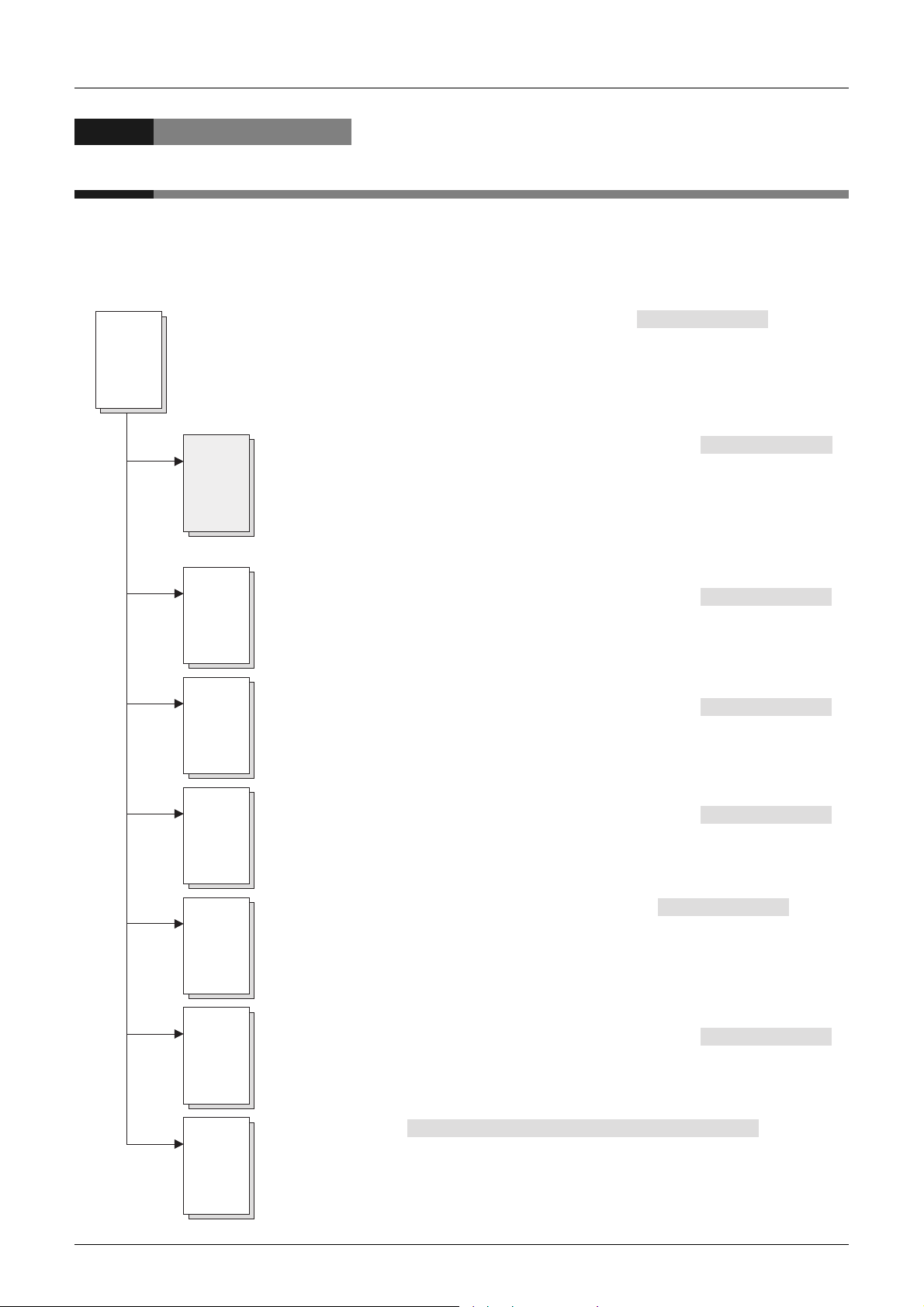
This manual explains devices and parameters for structured programs provided by GX Works2. Refer to
other manuals for sequence instructions and application functions.
Refer to each corresponding manual for analog, communication, positioning control and special units and
blocks.
1. When using FX3S/FX3G/FX3GC/FX3U/FX3UC PLCs
MELSEC-Q/L/F Structured Programming Manual (Fundamentals)
Q/L/F
Structured
This manual explains programming methods, specifications, functions, etc. required to create
structured programs.
(This manual)
FXCPU Structured Programming Manual [Device & Common]
FX
This manual explains devices and parameters for structured programs provided
by GX Works2.
Positioning of This Manual
(Additional Manual)
(Additional Manual)
Structured
FX
Structured
FX
Structured
FX
3S
FX
3G
FX
3GC
FX
3U
FX
3UC
FX
FXCPU Structured Programming Manual [Basic & Applied Instruction]
(Additional Manual)
This manual explains sequence instructions for structured programs provided
by GX Works2.
FXCPU Structured Programming Manual [Application Functions]
(Additional Manual)
This manual explains application functions for structured programs provided
by GX Works2.
FX3S/FX3G/FX
3GC
/FX3U/FX
3UC
User's Manual- Analog Control Edition
(Additional Manual)
This manual explains details of analog special function blocks and analog special
adapters for FX
Explanation of instructions and instructions used in program examples are expressed
for GX Developer.
FX Series User's Manual -Data Communication Edition
This manual explains details of simple N:N link, parallel link, computer link, no-protocol
communication (RS and RS2 instructions), programming communication and inverter
communication for FX PLCs.
Explanation of instructions and instructions used in program examples are expressed
for GX Developer.
3S
/FX3G/FX
3GC
/FX3U/FX
3UC
PLCs and PID instruction.
(Additional Manual)
FX
3S
FX
3G
FX
3GC
FX
3U
FX
3UC
Special
unit/block
FX3S/FX3G/FX
This manual explains details of wiring, instructions and operations of the positioning
function built in FX
Explanation of instructions and instructions used in program examples are expressed
for GX Developer.
Individual manuals
This manual explains details of each special unit/block.
Explanation of instructions and instructions used in program examples are expressed
for GX Developer.
*1. Detailed explanation may be provided by a separate manual in some products.
3GC
/FX3U/FX
3S
/FX3G/FX
3UC
Series User's Manual -Positioning Edition
3GC
/FX3U/FX
3UC
PLC main units.
(Manual supplied with product or additional Manual )
(Additional Manual)
*1
6
Page 9
FXCPU Structured Programming Manual
[Device & Common]
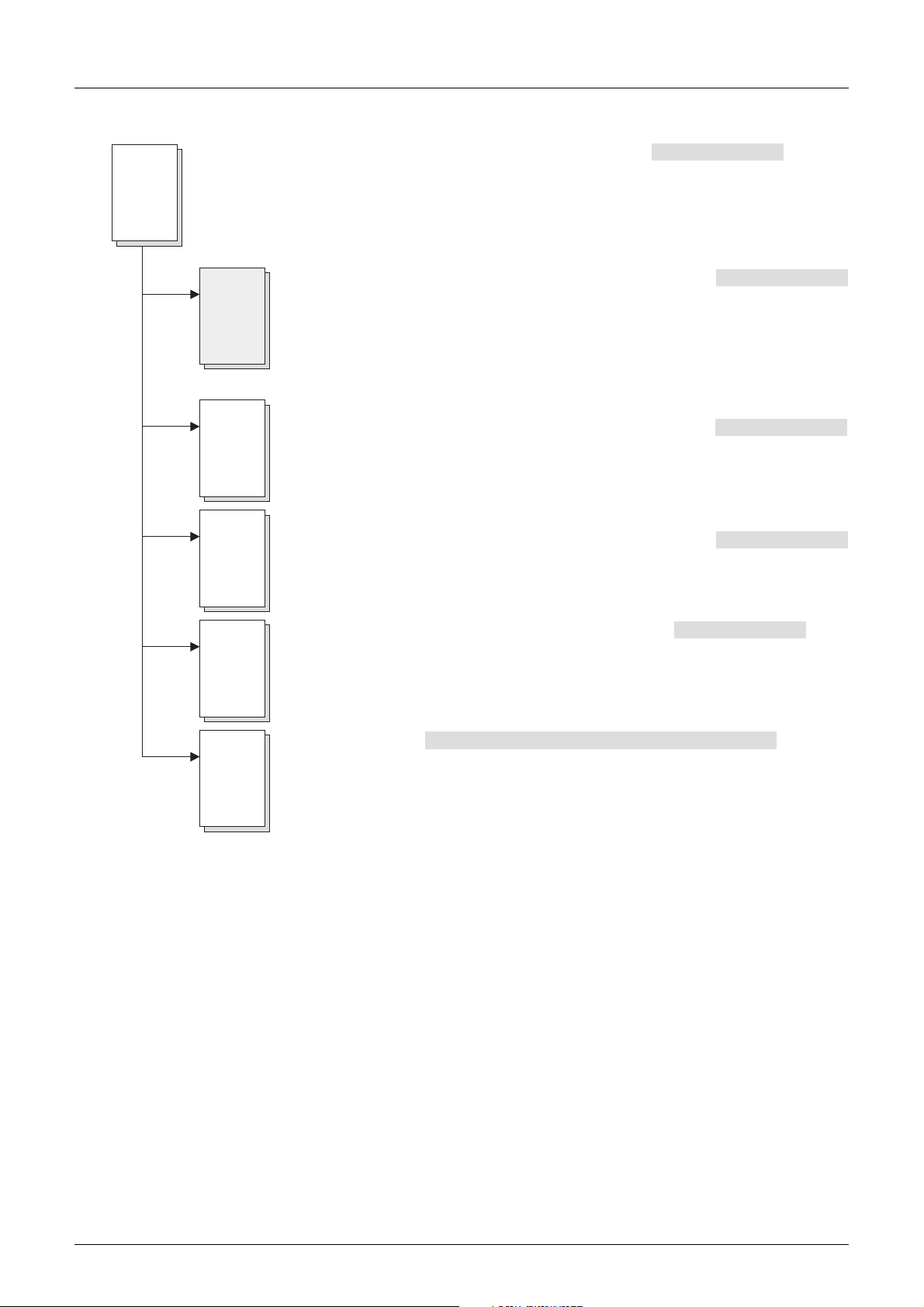
2. When using FX1S/FX1N/FX1NC/FX2N/FX2NC PLCs
Positioning of This Manual
Q/L/F
Structured
MELSEC-Q/L/F Structured Programming Manual [Fundamentals]
This manual explains programming methods, specifications, functions, etc. required to create
structured programs.
(This manual)
FXCPU Structured Programming Manual [Device & Common]
FX
Structured
This manual explains devices and parameters for structured programs provided
by GX Works2.
FXCPU Structured Programming Manual [Basic & Applied Instruction]
FX
This manual explains sequence instructions for structured programs provided
Structured
by GX Works2.
FXCPU Structured Programming Manual [Application Functions]
FX
This manual explains application functions for structured programs provided
Structured
by GX Works2.
(Additional Manual)
(Additional Manual)
(Additional Manual)
(Additional Manual)
FX
Special
unit/block
FX Series User's Manual -Data Communication Edition
This manual explains details of simple N:N link, parallel link, computer link, no-protocol
communication (RS instruction), programming communication and inverter communication
for FX PLCs.
Explanation of instructions and instructions used in program examples are expressed for
GX Developer and FX-PCS/WIN.
Individual manuals
This manual explains details of each special unit/block.
Explanation of instructions and instructions used in program examples are expressed
for GX Developer and FX-PCS/WIN.
*1. Detailed explanation may be provided by a separate manual in some products.
(Manual supplied with product or additional Manual )
(Additional Manual)
*1
7
Page 10
FXCPU Structured Programming Manual
[Device & Common]
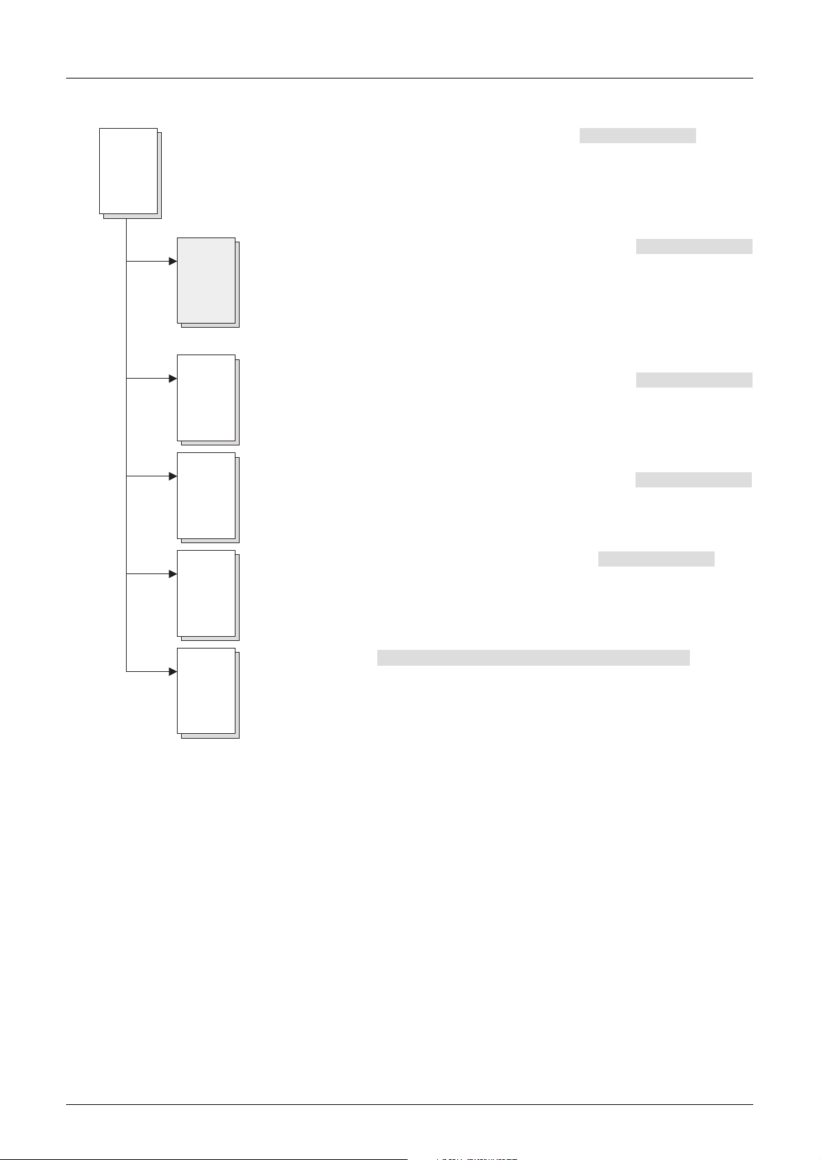
3. When using FX0S/X0/FX0N/FXU/FX2C PLCs
Positioning of This Manual
Q/L/F
Structured
MELSEC-Q/L/F Structured Programming Manual (Fundamentals)
This manual explains programming methods, specifications, functions, etc. required to create
structured programs.
(Additional Manual)
(This manual)
FXCPU Structured Programming Manual [Device & Common]
FX
Structured
This manual explains devices and parameters for structured programs provided
by GX Works2.
FXCPU Structured Programming Manual [Basic & Applied Instruction]
FX
This manual explains sequence instructions for structured programs provided
Structured
by GX Works2.
FXCPU Structured Programming Manual [Application Functions]
FX
This manual explains application functions for structured programs provided
Structured
by GX Works2.
(Additional Manual)
(Additional Manual)
(Additional Manual)
FX
Special
unit/block
FX Series User's Manual -Data Communication Edition
This manual explains details of parallel link, computer link, no-protocol communication
(RS instruction) and programming communication for FX PLCs.
Explanation of instructions and instructions used in program examples are expressed for
GX Developer and FX-PCS/WIN.
Individual manuals
This manual explains details of each special unit/block.
Explanation of instructions and instructions used in program examples are expressed
for GX Developer and FX-PCS/WIN.
*1. Detailed explanation may be provided by a separate manual in some products.
(Manual supplied with product or additional Manual )
(Additional Manual)
*1
8
Page 11
FXCPU Structured Programming Manual
[Device & Common]
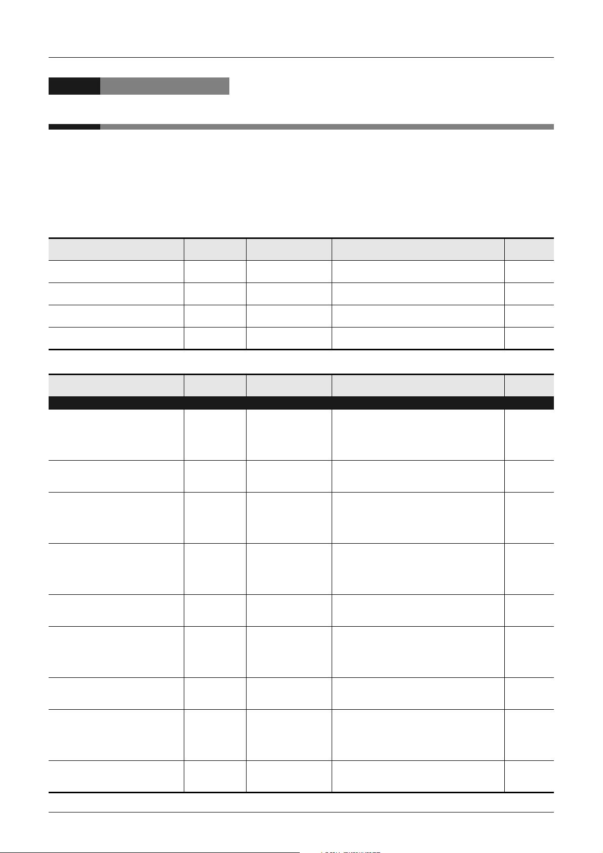
Related Manuals
This manual explains devices and parameters for structured programs provided by GX Works2.
Refer to other manuals for sequence instructions and applied functions.
This chapter introduces only reference manuals for this manual and manuals which describe the hardware
information of PLC main units.
Manuals not introduced here may be required in some applications.
Refer to the manual of the used PLC main unit and manuals supplied together with used products.
Contact the representative for acquiring required manuals.
Common among FX PLCs [structured]
Manual name Manual number
MELSEC-Q/L/F Structured
Programming Manual (Fundamentals)
FXCPU Structured Programming
Manual [Device & Common]
FXCPU Structured Programming
Manual [Basic & Applied Instruction]
FXCPU Structured Programming
Manual [Application Functions]
SH-080782 Additional Manual
JY997D26001 Additional Manual
JY997D34701 Additional Manual
JY997D34801 Additional Manual
Supplied with product
or Additional Manual
Related Manuals
Contents
Programming methods, specifications, functions,
etc. required to create structured programs
Devices, parameters, etc. provided in structured
projects of GX Works2
Sequence instructions provided in structured
projects of GX Works2
Application functions provided in structured
projects of GX Works2
Model
name code
13JW06
09R925
09R926
09R927
FX
3S/FX3G/FX3GC/FX3U/FX3UC PLCs
Manual name Manual number
PLC main unit
FX3U Series Hardware Manual JY997D18801 Supplied with product
FX3U Series User's Manual- Hardware
Edition
FX3UC (D, DS, DSS) Series Hardware
Manual
FX3UC-32MT-LT-2 Hardware Manual JY997D31601 Supplied with product
FX3UC Series User's Manual Hardware Edition
FX3G Series Hardware Manual JY997D46001 Supplied with product
3G Series User's Manual- Hardware
FX
Edition
FX3GC Series Hardware Manual JY997D45201 Supplied with product
FX3GC Series User's ManualHardware Edition
JY997D16501 Additional Manual
JY997D28601 Supplied with product
JY997D28701 Additional Manual
JY997D31301 Additional Manual
JY997D45401 Additional Manual
Supplied with product
or Additional Manual
Contents
I/O specifications, wiring and installation of the
PLC main unit FX3U extracted from the FX3U
Series User’s Manual - Hardware Edition. For
detailed explanation, refer to the FX3U Series
User’s Manual - Hardware Edition.
Details about the hardware including I/O
specifications, wiring, installation and
maintenance of the FX3U PLC main unit.
I/O specifications, wiring and installation of the
PLC main unit FX3UC (D, DS, DSS) extracted
from the FX3UC Series User’s Manual - Hardware
Edition. For detailed explanation, refer to the
FX3UC Series User’s Manual - Hardware Edition.
I/O specifications, wiring and installation of the
PLC main unit FX3UC-32MT-LT-2 extracted from
the FX3UC Series User’s Manual - Hardware
Edition. For detailed explanation, refer to the
FX3UC Series User’s Manual - Hardware Edition.
Details about the hardware including I/O
specifications, wiring, installation and
maintenance of the FX3UC PLC main unit.
I/O specifications, wiring and installation of the
PLC main unit FX3G extracted from the FX3G
Series User’s Manual - Hardware Edition. For
detailed explanation, refer to the FX3G Series
User’s Manual - Hardware Edition.
Details about the hardware including I/O
specifications, wiring, installation and
maintenance of the FX
I/O specifications, wiring and installation of the
PLC main unit FX3GC extracted from the FX3GC
Series User's Manual - Hardware Edition. For
detailed explanation, refer to the FX3GC Series
User's Manual - Hardware Edition.
Details about the hardware including I/O
specifications, wiring, installation and
maintenance of the FX3GC PLC main unit.
3G PLC main unit.
Model
name code
-
09R516
-
-
09R519
-
09R521
-
09R533
9
Page 12
FXCPU Structured Programming Manual
[Device & Common]
Related Manuals
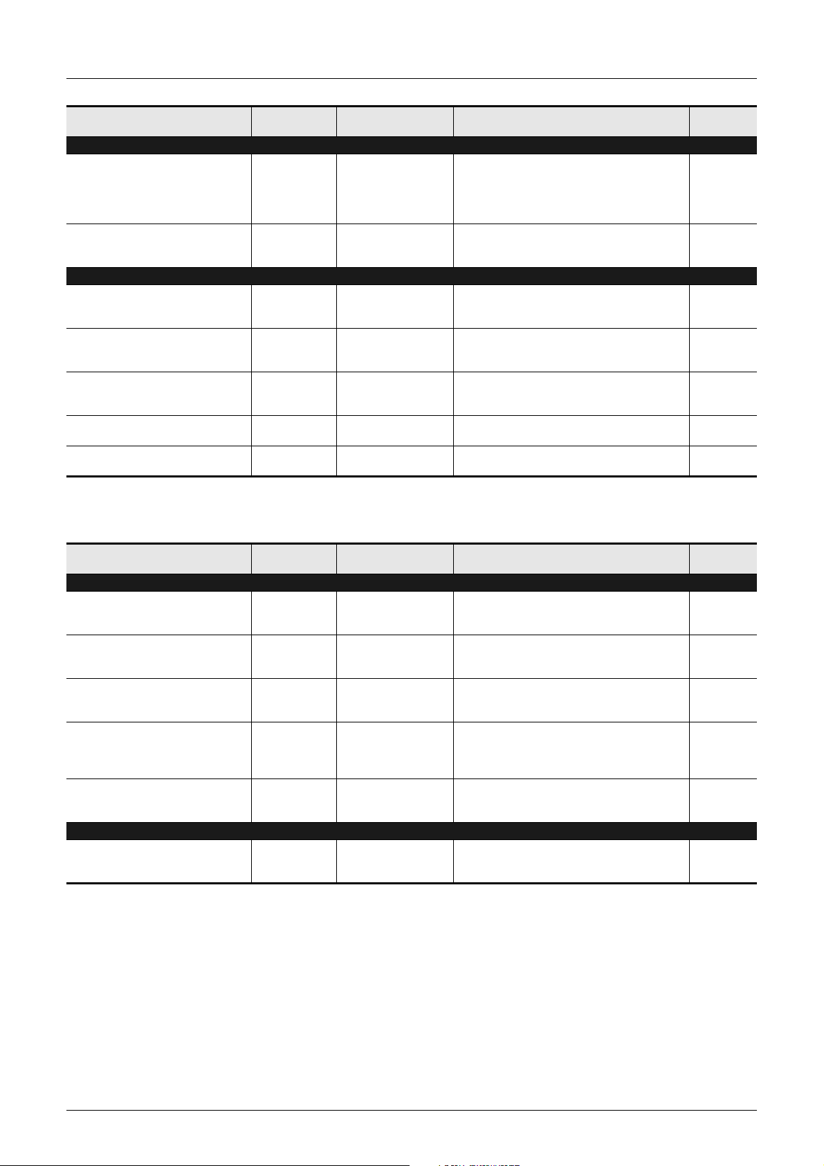
Manual name Manual number
PLC main unit
FX3S Series Hardware Manual JY997D48301 Supplied with product
FX3S Series User's Manual Hardware Edition
Programming
FX3S/FX3G/FX3GC/FX3U/FX3UC User's
Manual- Analog Control Edition
FX Series User's Manual -Data
Communication Edition
FX3S/FX3G/FX3GC/FX3U/FX3UC Series
User's Manual - MODBUS Serial
Communication Edition
FX3S/FX3G/FX3GC/FX3U/FX3UC Series
User's Manual -Positioning Edition
FX3U-CF-ADP User's Manual JY997D35401 Additional Manual
JY997D48601 Additional Manual
JY997D16701 Additional Manual
JY997D16901 Additional Manual
JY997D26201 Additional Manual
JY997D16801 Additional Manual
Supplied with product
or Additional Manual
FX1S/FX1N/FX1NC PLCs
FX
2N/FX2NC PLCs [whose production is finished]
Contents
I/O specifications, wiring and installation of the
PLC main unit FX3S extracted from the FX3S
Series User's Manual - Hardware Edition. For
detailed explanation, refer to the FX3S Series
User's Manual - Hardware Edition.
Details about the hardware including I/O
specifications, wiring, installation and
maintenance of the FX3S PLC main unit.
Details about the analog special function block
(FX3U-4AD, FX3U-4DA, FX3UC-4AD) and analog
special adapter (FX3U-****-ADP).
Details about simple N : N link, parallel link,
computer link and no-protocol communication
(RS instruction and FX2N-232IF).
Explains the MODBUS serial communication
network in FX3S/FX3G/FX3GC/FX3U/FX3UC PLCs.
Details about the positioning function built in the
FX3S/FX3G/FX3GC/FX3U/FX3UC Series.
Describes details of the FX3U-CF-ADP CF card
special adapter.
Model
name code
-
09R535
09R619
09R715
09R626
09R620
09R720
Manual name Manual number
PLC main unit
FX1S HARDWARE MANUAL JY992D83901 Additional Manual
FX1N HARDWARE MANUAL JY992D89301 Additional Manual
FX2N HARDWARE MANUAL JY992D66301 Additional Manual
1NC HARDWARE MANUAL JY992D92101 Additional Manual
FX
FX2NC HARDWARE MANUAL JY992D76401 Additional Manual
Programming
FX Series User's Manual -Data
Communication Edition
JY997D16901 Additional Manual
Supplied with product
or Additional Manual
Contents
Details about the hardware including I/O
specifications, wiring, installation and
maintenance of the FX1S PLC main unit.
Details about the hardware including I/O
specifications, wiring, installation and
maintenance of the FX1N PLC main unit.
Details about the hardware including I/O
specifications, wiring, installation and
maintenance of the FX2N PLC main unit.
Details about the hardware including I/O
specifications, wiring, installation and
maintenance of the FX
(Japanese only)
Details about the hardware including I/O
specifications, wiring, installation and
maintenance of the FX2NC PLC main unit.
Details about simple N : N link, parallel link,
computer link and no-protocol communication
(RS instruction and FX2N-232IF).
1NC PLC main unit.
Model
name code
-
-
09R508
09R505
09R509
09R715
10
Page 13
FXCPU Structured Programming Manual
[Device & Common]
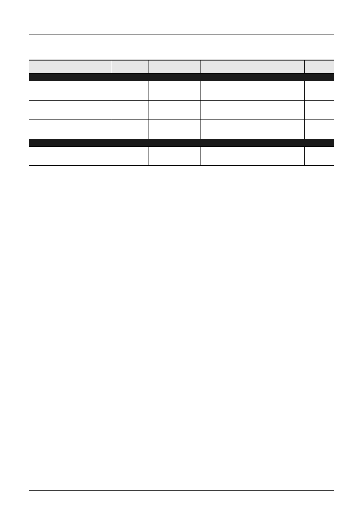
FX0S/FX0/FX0N/FXU/FX2C PLCs [whose production is finished]
Related Manuals
Manual name Manual number
PLC main unit
FX0/FX0N HARDWARE MANUAL JY992D47501 Supplied with product
FX0S HARDWARE MANUAL JY992D55301 Supplied with product
FX/FX2C HARDWARE MANUAL JY992D47401 Supplied with product
Programming
FX Series User's Manual -Data
Communication Edition
JY997D16901 Additional Manual
Supplied with product
or Additional Manual
Manuals of models whose production is finished
Production is finished for FX
0S/FX0/FX0N/FXU/FX2C/FX2N/FX2NC PLCs.
Contents
Details about the hardware including I/O
specifications, wiring, installation and
maintenance of the FX0/FX0N PLC main unit.
Details about the hardware including I/O
specifications, wiring, installation and
maintenance of the FX0S PLC main unit.
Details about the hardware including I/O
specifications, wiring, installation and
maintenance of the FXU/FX2C PLC main unit.
Details about simple N : N link, parallel link,
computer link and no-protocol communication
(RS instruction and FX2N-232IF).
Model
name code
-
-
-
09R715
11
Page 14
FXCPU Structured Programming Manual
[Device & Common]
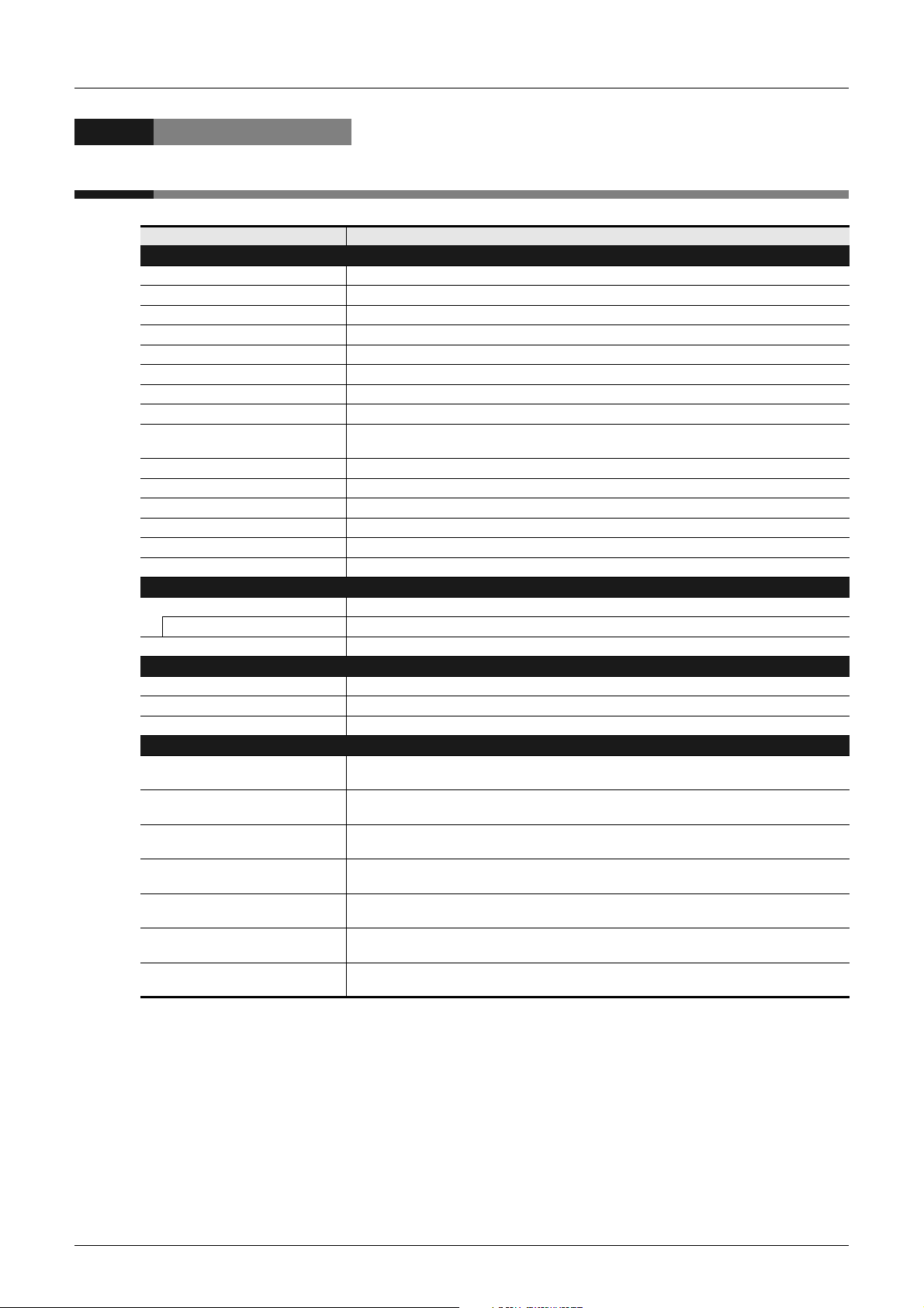
Generic Names and Abbreviations Used in Manuals
Generic Names and Abbreviations Used in Manuals
Abbreviation/generic name Name
PLCs
FX3U Series or FX3U PLC Generic name of FX3U Series PLCs
FX3UC Series or FX3UC PLC Generic name of FX3UC Series PLCs
FX3G Series or FX3G PLC Generic name of FX3G Series PLCs
FX3GC Series or FX3GC PLC Generic name of FX3GC Series PLCs
FX3S Series or FX3S PLC Generic name of FX3S Series PLCs
FX2N Series or FX2N PLC Generic name of FX2N Series PLCs
FX2NC Series or FX2NC PLC Generic name of FX2NC Series PLCs
FX1N Series or FX1N PLC Generic name of FX1N Series PLCs
FX1NC Series or FX1NC PLC
FX1S Series or FX1S PLC Generic name of FX1S Series PLCs
FXU Series or FXU PLC Generic name of FXU(FX,FX2) Series PLCs
FX2C Series or FX2C PLC Generic name of FX2C Series PLCs
FX0N Series or FX0N PLC Generic name of FX0N Series PLCs
FX0S Series or FX0S PLC Generic name of FX0S Series PLCs
FX0 Series or FX0 PLC Generic name of FX0 Series PLCs
Special adapters
CF card special adapter Generic name of CF card special adapters
CF-ADP FX3U-CF-ADP
Ethernet adapter Abbreviated name for FX3U-ENET-ADP
Programming language
ST Abbreviation of structured text language
Structured ladder Abbreviation of ladder diagram language
FBD Abbreviation of function block diagram language
Manuals
Q/L/F Structured Programming
Manual (Fundamentals)
FX Structured Programming Manual
[Device & Common]
FX Structured Programming Manual
[Basic & Applied Instruction]
FX Structured Programming Manual
[Application Functions]
COMMUNICATION CONTROL
EDITION
ANALOG CONTROL EDITION
POSITIONING CONTROL EDITION
Generic name of FX1NC Series PLCs
These products can only used in Japan.
Abbreviation of MELSEC-Q/L/F Structured Programming Manual (Fundamentals)
Abbreviation of FXCPU Structured Programming Manual [Device & Common]
Abbreviation of FXCPU Structured Programming Manual [Basic & Applied Instruction]
Abbreviation of FXCPU Structured Programming Manual [Application Functions]
Abbreviation of FX Series User's Manual-DATA COMMUNICATION CONTROL EDITION
Abbreviation of FX3S/FX3G/FX3GC/FX3U/FX3UC Series User's Manual-ANALOG CONTROL
EDITION
Abbreviation of FX3S/FX3G/FX3GC/FX3U/FX3UC Series User's Manual-POSITIONING CONTROL
EDITION
12
Page 15
FXCPU Structured Programming Manual
[Device & Common]
1. Device Outline
1 Device Outline
1.1 Devices Constructing PLC
1
Device Outline
This chapter explains basic contents of devices.
1.1 Devices Constructing PLC
Each PLC has many built-in relays, timers, counters, etc.
Each of which has many normally-open contacts and normally-closed contacts.
Connect these contacts and coils to construct a program.
Each PLC also has built-in memory devices including data registers (D) and extension registers (R) to store
numeric data.
Constant
2
Devices in
Detail
3
Specified the
Device &
4
Special Device
5
Errors
6
Types and
Setting of
Parameters
7
Other Functions
13
Page 16
FXCPU Structured Programming Manual
[Device & Common]
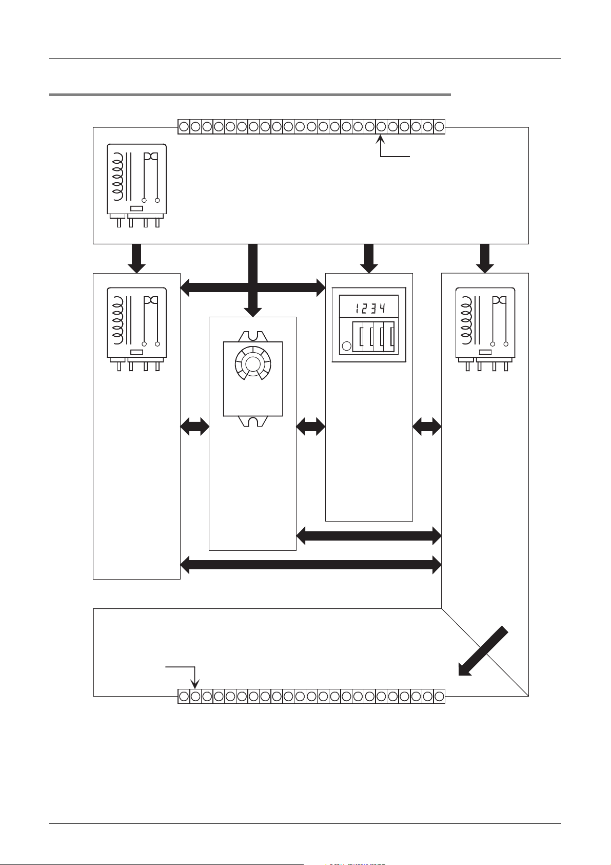
1.1.1 Relation among devices
Arrow indicates signal transfer.
Input relay: X
The PLC receives signals from external input switches via input relays.
The symbol of input relay is "X".
The PLC has built-in input relays in accordance with its scale.
1 Device Outline
1.1 Devices Constructing PLC
Input terminal or
input connector
Auxiliary relay: M
The PLC has many
built-in auxiliary
relays.
The symbol of
auxiliary relay is "M".
State relay: S
The PLC has many
built-in state relays.
The symbol of state
relay is "S".
Timer: T
The PLC has many
built-in timers.
The symbol of timer
is "T".
4123
Counter: C
The PLC has many
built-in counters.
The symbol of
counter is "C".
Output relay: Y
The PLC drives
external loads via
output relays.
The PLC has many
built-in output relays.
The symbol of
output relay is "Y".
14
Contact (one normally-open contact) for external output of output relay
The PLC has built-in output contacts in accordance with its scale.
Output terminal or
output connector
Page 17

FXCPU Structured Programming Manual
[Device & Common]
1.1.2 Device function list
1. Input relay (X) and output relay (Y)
• In the PLC main unit, input relays and output relays are assigned with serial octal numbers such as "X000
to X007", "X010 to X017", "Y000 to Y007" and "Y010 to Y017".
In extension units and extension blocks, input relays and output relays are also assigned with serial octal
numbers in the connection order from the PLC main unit.
• Digital filters are used in specified input relays, and the filter value can be changed in programs.
Accordingly, assign input relay numbers having input filter for applications requiring high-speed receiving.
(Refer to explanation of filter adjustment, input interrupt, high speed counter and various instructions.)
2. Auxiliary relay (M)
• Auxiliary relays are built in the PLC. Different from input relays and output relays, auxiliary relays cannot
receive external inputs or cannot drive external loads directly.
Auxiliary relays are available only in programs.
• In some auxiliary relays, the ON/OFF status is backed up against interruption of the PLC power.
3. State relay (S)
• State relays are used as process numbers in the step ladder.
• If state relays are not used as process numbers, they can be programmed as general contacts/coils in the
same way as auxiliary relays.
• State relays can be used as annunciators for external failure diagnosis.
1 Device Outline
1.1 Devices Constructing PLC
→ Refer to Section 2.2.
→ Refer to Section 2.3.
→ Refer to Section 2.4.
Constant
1
Device Outline
2
Devices in
Detail
3
Specified the
Device &
4
Special Device
5
Errors
4. Timer (T)
→ Refer to Section 2.5.
• Timers count clock pulses (1 ms, 10 ms, 100 ms, etc.) inside the PLC.
When the count value reaches the set value, output contacts are activated.
Timers can measure 0.001 to 3276.7 seconds in accordance with the base clock pulse.
5. Counter (C)
Counters are classified into the following types, and can be used for suitable purposes and applications.
1) Counter (latched type)
→ Refer to Section 2.6.
Counters are used for signals inside the PLC. The response speed is several tens of Hz or less usually.
- 16-bit counter: For up-counting, counting range: 1 to 32767
- 32-bit counter: For up/down-counting, counting range: -2,147,483,648 to +2,147,483,647
2) High speed counter (latched type backed up against power interruption)
→ Refer to Section 2.7.
High speed counters can count several kHz without regard to operations in the PLC.
- 32-bit counter: For up/down-counting, counting range: -2,147,483,648 to +2,147,483,647
(1-phase 1-counting, 1-phase 2 counting or 2-phase 2 counting) assigned to specific input relays
6. Data register (D)
→ Refer to Section 2.8.
Data registers store numeric data.
FX PLCs have only 16-bit data registers (whose most significant bit indicates the positive or negative sign),
but two combined data registers can handle 32-bit numeric value (whose most significant bit indicates the
positive or negative sign). (Refer to "5. Counter" for the available numeric range.)
Data registers are classified into the general type and the latched type (backed up against power interruption)
in the same way as other devices.
6
Types and
Setting of
Parameters
7
Other Functions
15
Page 18

FXCPU Structured Programming Manual
[Device & Common]
7. Extension register (R) and extension file register (ER)
Only FX
Extension registers(R) are extended type of data registers (D), and backed up against power interruption by
battery in FX
In FX
is connected.
FX
(ER). However, FX
attached.
8. Index register (V and Z)
Registers (V) (Z) are available for indexing.
Add index registers (V) (Z) to other devices as follows:
[In the case of "V0 = 5, Z0 = 5]
D100V0 = D105, C20Z0 = C25 ← Device number + Value of V
Data registers and index registers are used to indirectly specify set values of timers and counters, or used in
instructions.
9. Pointer (P and I)
Pointers are classified into the branch type and the interrupt type.
• Branch pointers (P) specify the jump destination of the CJ (FNC 00: Conditional jump) and CALL
• Interrupt pointers (I) specify the interrupt routine for input interrupt, timer interrupt or counter interrupt.
3G/FX3GC/FX3U/FX3UC PLCs support extension registers (R) and extension file registers (ER).
3U/FX3UC PLCs.
3G/FX3GC PLCs, general type devices can be backed up against power interruption if an optional battery
3G/FX3GC/FX3U/FX3UC PLCs can store the contents of extension registers (R) in extension file registers
3U/FX3UC PLCs can use extension file registers (ER) only while a memory cassette is
(subroutine call) instructions.
1 Device Outline
1.1 Devices Constructing PLC
→ Refer to Section 2.9.
→ Refer to Section 2.10.
or Z
→ Refer to Section 2.11.
10.Constant (K, H and E)
→ Refer to Chapter 3.
Among various numeric values used in PLCs, "K" indicates "decimal integer", "H" indicates "hexadecimal
value", and "E" indicates "real number (floating point data)".
Constants are used for set values and current values of timers and counters as well as input variables of
instructions.
16
Page 19
FXCPU Structured Programming Manual
[Device & Common]
1.2 Program Memory and Devices
1.2.1 Memory structure
1 Device Outline
1.2 Program Memory and Devices
1
Device Outline
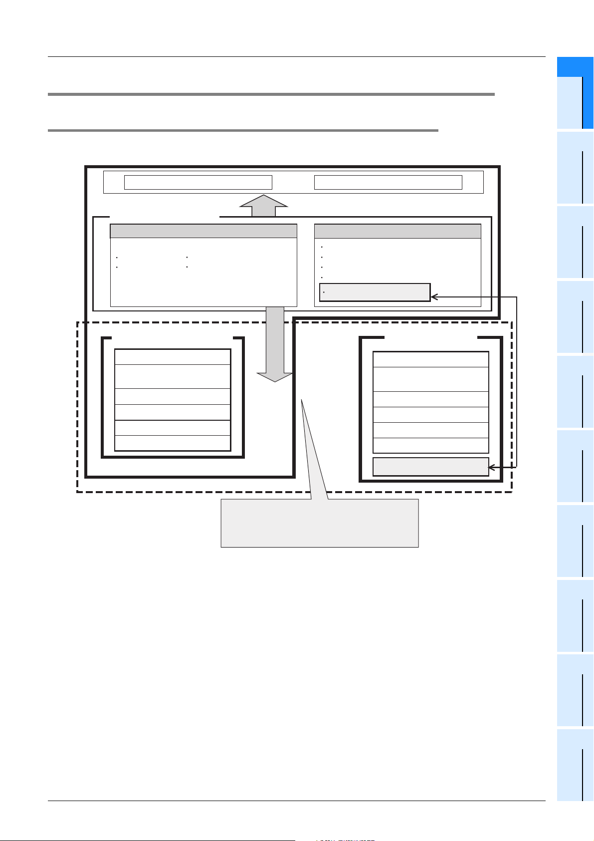
1. FX3U and FX3UC PLCs
CPU System ROM
Built-in device memory(RAM)
[Bit device memory]
Contact image memory
Input relay (X) Output relay (Y)
Auxiliary relay (M) State relay (S)
Timer contact, time counting coil,
counter contact, counting coil and reset coil
Built-in program memory(RAM)
Parameter
Sequence program
Comment
File register (D)
Special setting
Symbolic information
2
Devices in
Detail
3
Specified the
Device &
[Data memory]
Data register (D)
Timer current value register (T)
Counter current value register (C)
Index register (V and Z)
Extension register (R)
Optional memory
(Flash memory)
Parameter
Sequence program
Comment
File register (D)
Special setting
*1
Symbolic information
*1
Transfer/initialization by instruction
Constant
Parameters
4
Special Device
5
Errors
6
Types and
Setting of
*1. Supported in Ver. 3.00 or later.
Extension file register (ER)
The PLC automatically recognizes attachment of
an optional memory (when the power is turned ON),
and isolates the built-in program memory.
(The PLC gives the priority to the optional memory.)
7
Other Functions
17
Page 20
FXCPU Structured Programming Manual
[Device & Common]
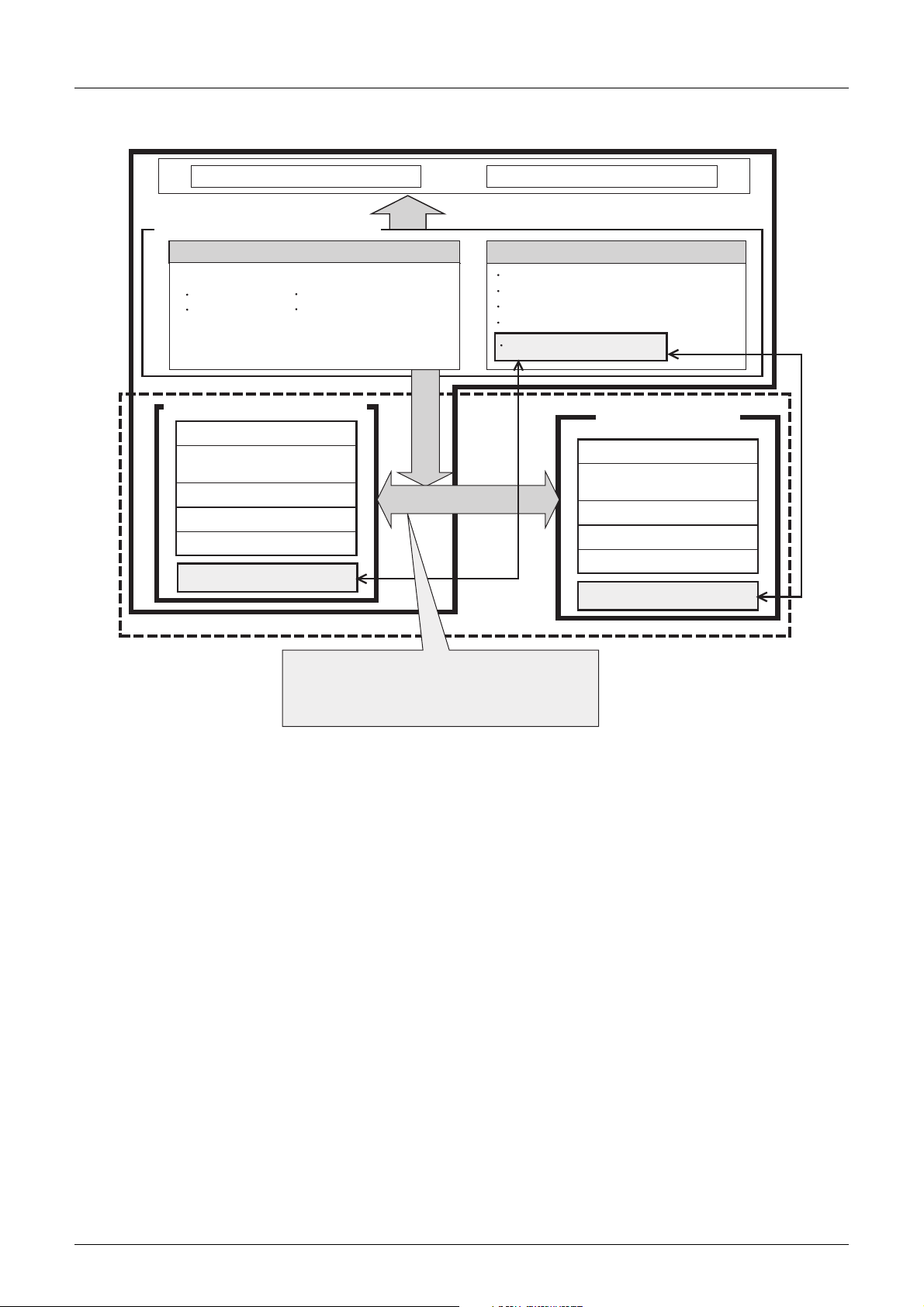
2. FX3G and FX3GC PLCs
CPU System ROM
Built-in device memory(RAM, EEPROM)
[Bit device memory] [Data memory]
Contact image memory
Input relay (X) Output relay (Y)
Auxiliary relay (M) State relay (S)
Timer contact, time counting coil, reset coil (T),
counter contact, counting coil and reset coil (C)
Built-in program memory(EEPROM)
Parameter
Sequence program
Comment
File register (D)
Special setting
Extension file register (ER)
Data register (D)
Timer current value register (T)
Counter current value register (C)
Index register (V and Z)
Extension register (R)
Transfer/initialization
by instruction
1.2 Program Memory and Devices
Optional memory
(EEPROM)
Parameter
Sequence program
Comment
File register (D)
Special setting
Extension file register (ER)
*1
1 Device Outline
Transfer/initialization by instruction
The PLC automatically recognizes attachment of
an optional memory
and isolates the built-in program memory.
(The PLC gives the priority to the optional memory.)
*1
(when the power is turned ON),
*1. Optional memory cannot be connected to FX3GC PLCs.
18
Page 21
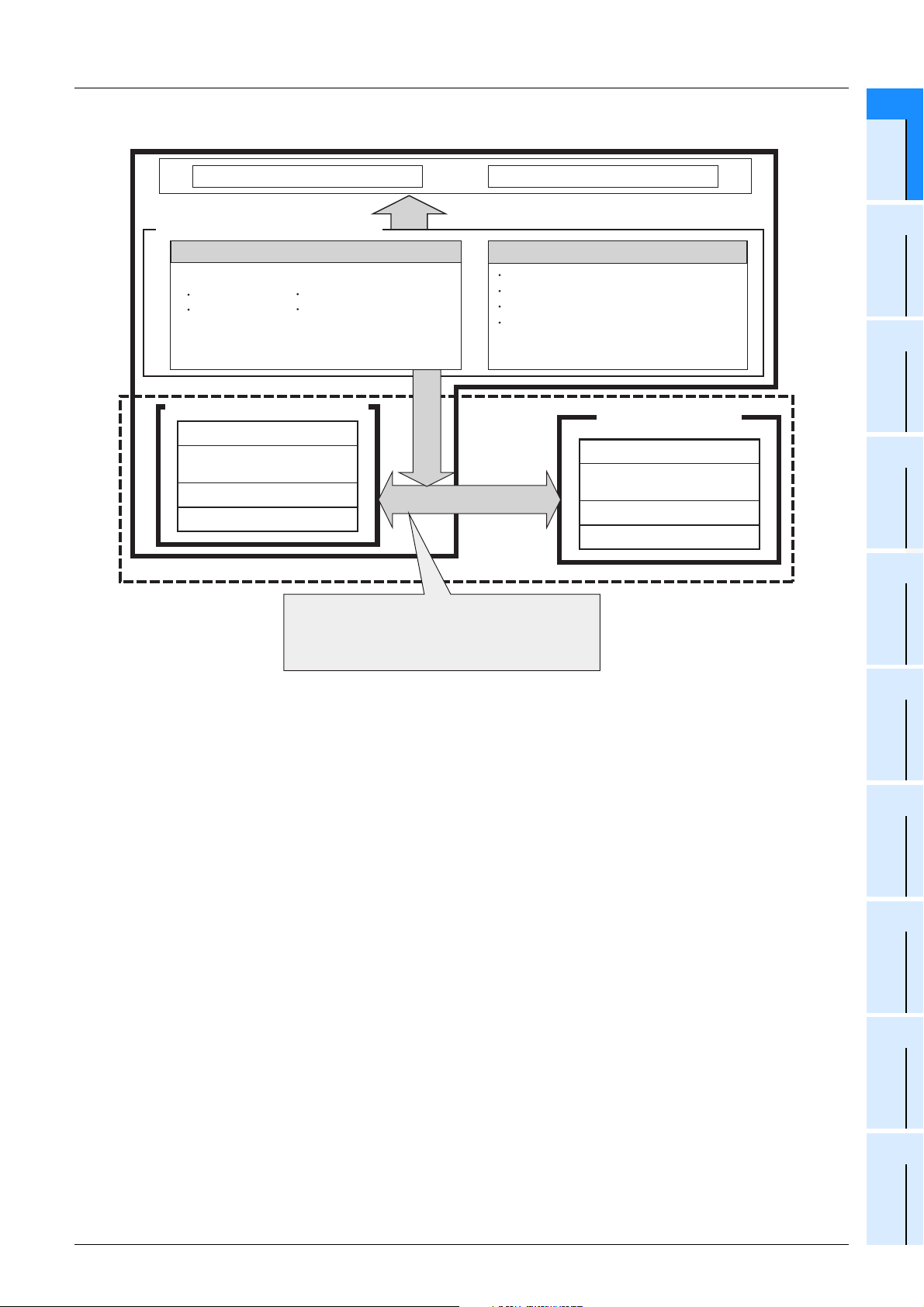
FXCPU Structured Programming Manual
[Device & Common]
3. FX3S PLCs
CPU System ROM
1 Device Outline
1.2 Program Memory and Devices
1
Device Outline
Built-in device memory(RAM, EEPROM)
[Bit device memory] [Data memory]
Contact image memory
Input relay (X) Output relay (Y)
Auxiliary relay (M) State relay (S)
Timer contact, time counting coil, reset coil (T),
counter contact, counting coil and reset coil (C)
Built-in program memory(EEPROM)
Parameter
Sequence program
Comment
File register (D)
The PLC automatically recognizes attachment of
an optional memory (when the power is turned ON),
and isolates the built-in program memory.
(The PLC gives the priority to the optional memory.)
Data register (D)
Timer current value register (T)
Counter current value register (C)
Index register (V and Z)
Optional memory
(EEPROM)
Parameter
Sequence program
Comment
File register (D)
Constant
2
Devices in
Detail
3
Specified the
Device &
4
Special Device
5
Errors
6
Types and
Setting of
Parameters
7
Other Functions
19
Page 22
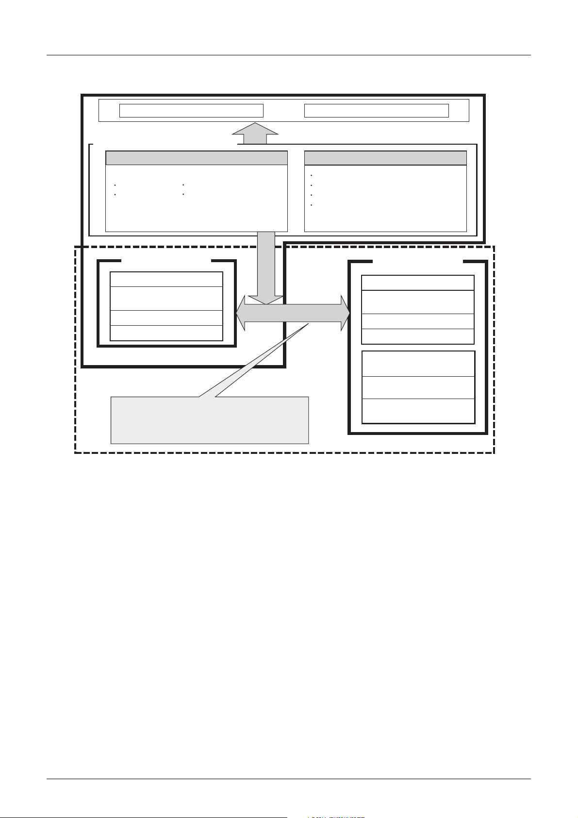
FXCPU Structured Programming Manual
[Device & Common]
4. FX1S/FX1N/FX2N/FX1NC/FX2NC PLCs
CPU System ROM
Built-in device memory(RAM, EEPROM)
[Bit device memory] [Data memory]
1 Device Outline
1.2 Program Memory and Devices
Contact image memory
Input relay (X) Output relay (Y)
Auxiliary relay (M) State relay (S)
Timer contact, time counting coil, reset coil (T),
counter contact, counting coil and reset coil (C)
Built-in program memory
(RAM, EEPROM)
Parameter
Sequence program
Comment
File register (D)
The PLC automatically recognizes attachment of
an optional memory
and isolates the built-in program memory.
(The PLC gives the priority to the optional memory.)
*1
(when the power is turned ON),
Data register (D)
Timer current value register (T)
Counter current value register (C)
Index register (V and Z)
Optional memory
(RAM,EEPROM,EPROM)
Parameter
Sequence program
Comment
File register (D)
Clock function
2NC-EEPROM16C)
(FX
Extension function
2N-ROM-E1)
(FX
Clock function + Extension function
(FX2NC-ROM-CE1)
*1
*1. Optional memory cannot be connected to FX1NC PLCs.
20
Page 23
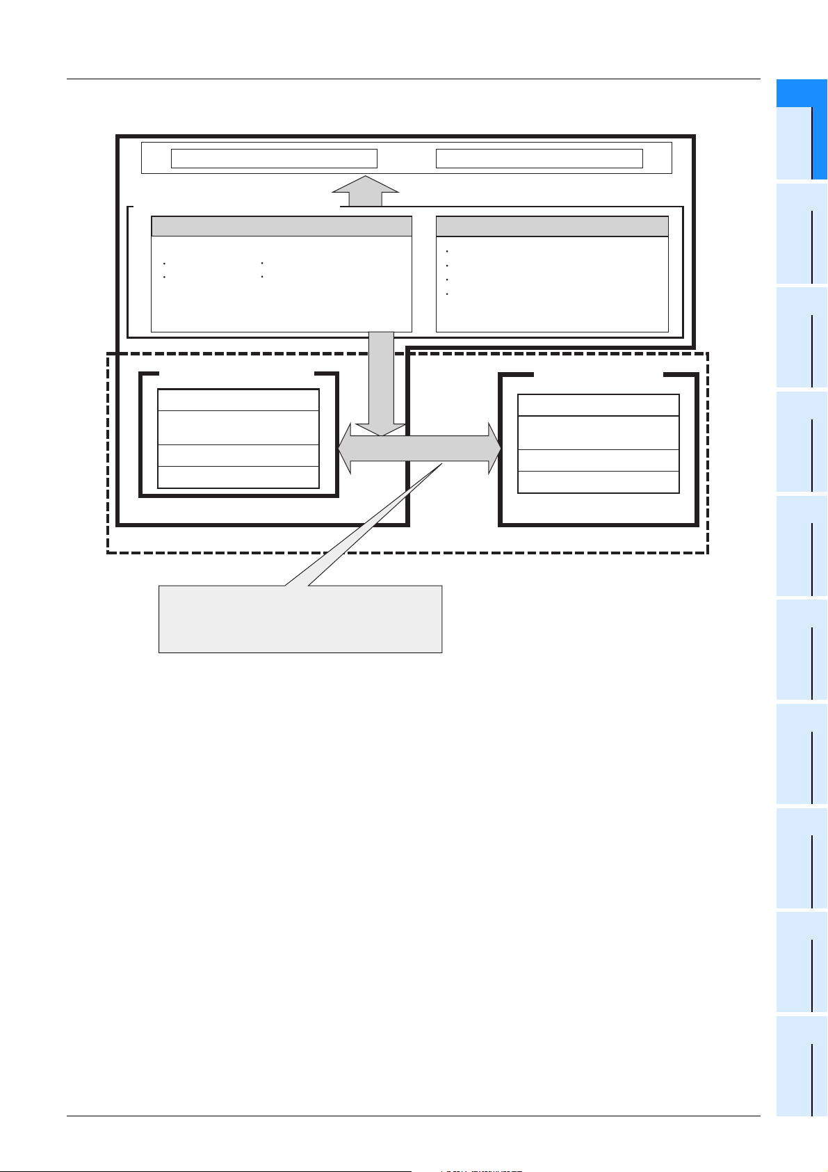
FXCPU Structured Programming Manual
[Device & Common]
5. FX0S/FX0/FX0N/FXU/FX2C PLCs
CPU System ROM
1 Device Outline
1.2 Program Memory and Devices
1
Device Outline
Built-in device memory(RAM, EEPROM)
[Bit device memory] [Data memory]
Contact image memory
Input relay (X) Output relay (Y)
Auxiliary relay (M) State relay (S)
Timer contact, time counting coil, reset coil (T),
counter contact, counting coil and reset coil (C)
Built-in program memory
(RAM, EEPROM)
Parameter
Sequence program
Comment
File register (D)
The PLC automatically recognizes attachment of
an optional memory
and isolates the built-in program memory.
(The PLC gives the priority to the optional memory.)
*2
*1
(when the power is turned ON),
Data register (D)
Timer current value register (T)
Counter current value register (C)
Index register (V and Z)
Optional memory
(RAM,EEPROM,EPROM)
Parameter
Sequence program
Comment
File register (D)
2
Devices in
Detail
3
Specified the
Device &
Constant
*1
4
Special Device
*2
5
Errors
6
Types and
Setting of
Parameters
*1. Optional memory cannot be connected to FX0S/FX0 PLCs.
*2. FX
0S/FX0 PLCs do not support file registers.
7
Other Functions
21
Page 24
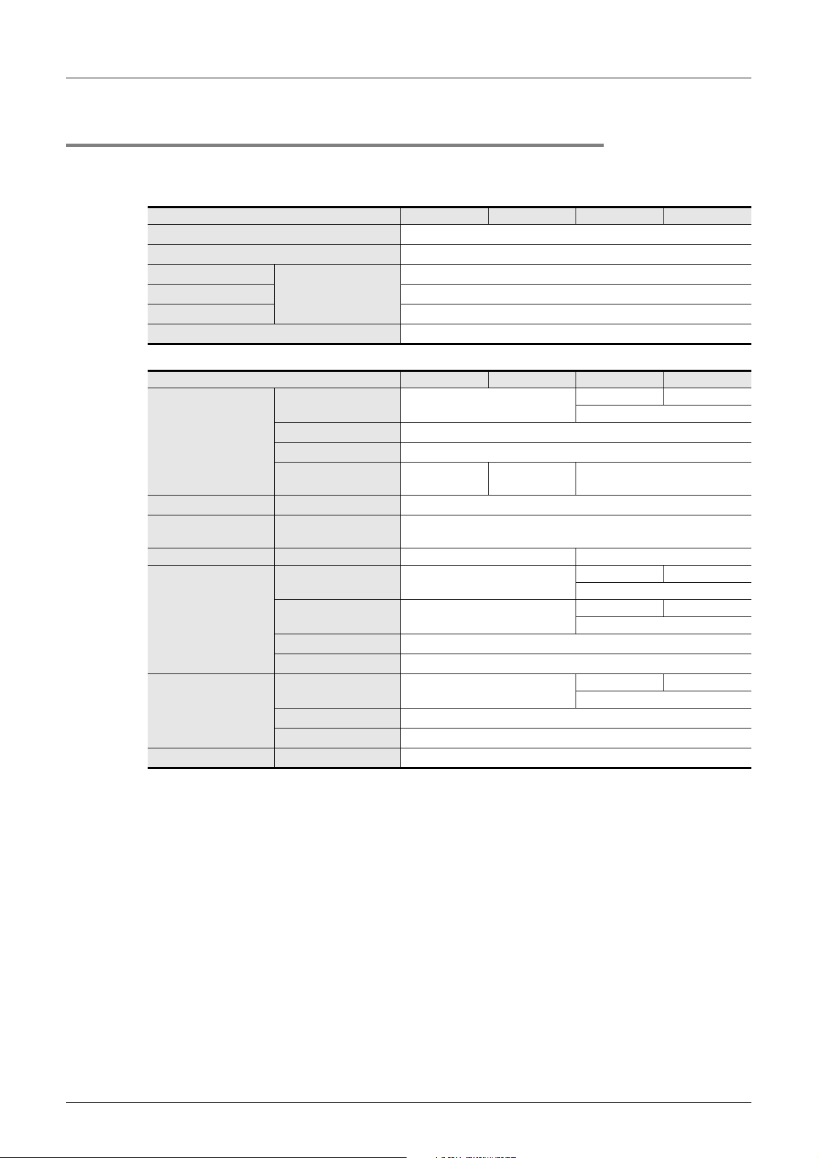
FXCPU Structured Programming Manual
[Device & Common]
1.2 Program Memory and Devices
1 Device Outline
1.2.2 Memory operations and backup against power interruption (power ON/OFF and RUN/STOP)
1. FX3U/FX3UC PLCs
1) Types of program memory
Item Power OFF Power OFF→ON STOP→RUN RUN→STOP
Parameter
Sequence program
Comment
File register
Special setting
Symbolic information
Can be secured by
parameter setting.
*1
Does not change.
Does not change.
Does not change.
Does not change.
Does not change.
Does not change.
2) Types of word device memory
Item Power OFF Power OFF→ON STOP→RUN RUN→STOP
General type Cleared.
Data register (D)
Extension register (R) Latched (backed-up) type
Extension file register
*5
(ER)
Index register (V and Z) V, Z Cleared. Does not change.
Timer current value
register (T)
Counter current value
register (C)
Clock data Current value
Latched (backed-up) type
File type
Special type Cleared.
File type Does not change.
For 100 ms Cleared.
For 10 ms Cleared.
Retentive type for 100 ms
Retentive type for 1 ms
General type Cleared.
Latched (backed-up) type
High speed type
Does not change.
Does not change.
Set to initial
*4
value.
Does not change.
Does not change.
Does not change.
Does not change.
Does not change.
Does not change.
*2
*2
*2
*2
*2
*2
Does not change. Cleared.
Does not change while M8033 is ON.
*3
*2
Does not change.
*3
Does not change. Cleared.
Does not change while M8033 is ON.
Does not change. Cleared.
Does not change while M8033 is ON.
*3
*3
Does not change. Cleared.
Does not change while M8033 is ON.
*3
*3
*3
*4
22
*1. Available in Ver. 3.00 or later.
*2. The program memory contents or device status is not held correctly when the battery voltage
becomes lower than the holding voltage if a memory cassette is not attached.
*3. The device status is not held correctly when the battery voltage becomes lower than the holding
voltage.
*4. Some devices are cleared when the PLC mode switches from STOP to RUN.
→ For special data registers, refer to Chapter 4.
*5. An optional memory cassette is required.
Page 25
FXCPU Structured Programming Manual
[Device & Common]
• Caution
When the battery voltage becomes low due to expiration of the battery life or another reason, programs
(not stored in a memory cassette), latched (backed-up) type devices and clock data are not held correctly.
Clear latched type devices, and transfer programs (not stored in a memory cassette) again. In addition, set
the initial values and clock data if necessary.
→ For rough guide to the life and replacement timing of the battery, refer to the User's Manual
→ For the latched type device clear method, refer to Subsection 1.2.5.
3) Types of bit device memory
Item Power OFF Power OFF→ON STOP→RUN RUN→STOP
Input relay (X) Cleared.
Output relay (Y) Cleared.
General type auxiliary
relay (M)
Latched (backed-up) type
Contact image memory
(X, Y, M, S)
Timer contact
Time counting coil
Reset coil (T)
Counter contact
Counting coil
Reset coil (C)
*1. Some devices are cleared when the PLC mode switches from STOP to RUN.
*2. When the battery voltage becomes lower than the holding voltage, the device status is not held
correctly.
auxiliary relay (M)
Special auxiliary relay (M) Cleared.
General type state relay
(S)
Latched (backed-up) type
state relay (S)
Annunciator (S) Cleared.
For 100 ms Cleared.
For 10 ms Cleared.
Retentive type for 100 ms Does not change.
Retentive type for 1 ms Does not change.
General type Cleared.
Latched (backed-up) type Does not change.
High speed type Does not change.
1 Device Outline
1.2 Program Memory and Devices
[Hardware Edition] of each PLC.
Does not change.
Does not change while M8033 is ON.
Does not change. Cleared.
Does not change while M8033 is ON.
Cleared.
Does not change.
Set to initial
value.
Cleared.
Does not change.
Does not change. Cleared.
Does not change while M8033 is ON.
*1
Does not change.
Does not change. Cleared.
Does not change while M8033 is ON.
Does not change. Cleared.
Does not change while M8033 is ON.
Does not change. Cleared.
Does not change while M8033 is ON.
Does not change. Cleared.
Does not change while M8033 is ON.
Does not change. Cleared.
Does not change while M8033 is ON.
*1
→ For special auxiliary relays, refer to Chapter 4.
1
Device Outline
2
Devices in
Detail
3
Specified the
Device &
Constant
4
Special Device
5
Errors
6
Types and
Setting of
Parameters
7
Other Functions
23
Page 26
FXCPU Structured Programming Manual
[Device & Common]
2. FX3G/FX3GC PLCs
1) Types of program memory
Item Power OFF Power OFF→ON STOP→RUN RUN→STOP
Parameter
Sequence program
Comment
File register
2) Types of word device memory
Data register (D)
Extension register (R) General type
Extension file register
(ER)
Index register (V and Z) V, Z Cleared. Does not change.
Timer current value
register (T)
Counter current value
register (C)
Clock data Current value
Can be secured by
parameter setting.
Item Power OFF Power OFF→ON STOP→RUN RUN→STOP
General type
Latched (backed-up) type
File type
Special type Cleared.
File type Does not change.
For 100 ms Cleared.
For 10 ms Cleared.
For 1 ms Cleared.
Retentive type for 100 ms
Retentive type for 1 ms
General type Cleared.
Latched (backed-up) type
High speed type Does not change.
Cleared.
Cleared.
Does not change.
Does not change.
Does not change.
Does not change.
*1
Does not change.
Does not change.
Set to initial
*2
value.
*1
Does not change.
Does not change.
Does not change.
Does not change.
1 Device Outline
1.2 Program Memory and Devices
Does not change. Cleared.
Does not change while M8033 is ON.
Does not change.
Does not change.
Does not change. Cleared.
Does not change while M8033 is ON.
Does not change. Cleared.
Does not change while M8033 is ON.
Does not change. Cleared.
Does not change while M8033 is ON.
Does not change. Cleared.
Does not change while M8033 is ON.
*3
*2
24
*1. General type devices can be changed to the latched type by parameter setting if an optional battery is
attached.
*2. Some devices are cleared when the PLC mode switches from STOP to RUN.
→ For special data registers, refer to Chapter 4.
*3. The clock data is held by the power accumulated in the large-capacity capacitor built in the PLC.
The clock data is not held correctly if the voltage of the built-in large-capacity capacitor becomes low.
The large-capacity capacitor can hold the clock data for 10 days (when the ambient temperature is
25°C) if it is charged fully (by turning ON the PLC for 30 minutes or more).
The clock data is backed up by the battery when an optional battery is attached and the battery mode
is selected by parameter setting.
Page 27
FXCPU Structured Programming Manual
[Device & Common]
3) Types of bit device memory
Item Power OFF Power OFF→ON STOP→RUN RUN→STOP
Input relay (X) Cleared.
Output relay (Y) Cleared.
General type auxiliary
relay (M)
Contact image memory
(X, Y, M, S)
Timer contact
Time counting coil
Reset coil (T)
Counter contact
Counting coil
Reset coil (C)
*1. General type devices can be changed to the latched type by parameter setting if an optional battery is
attached.
*2. Some devices are cleared when the PLC mode switches from STOP to RUN.
Latched (backed-up) type
auxiliary relay (M)
Special auxiliary relay (M) Cleared.
General type state relay
(S)
Latched (backed-up) type
state relay (S)
Annunciator (S) Does not change.
For 100 ms Cleared.
For 10 ms Cleared.
For 1 ms Cleared.
Retentive type for 100 ms Does not change.
Retentive type for 1 ms Does not change.
General type Cleared.
Latched (backed-up) type Does not change.
High speed type Does not change.
1 Device Outline
1.2 Program Memory and Devices
Does not change. Cleared.
Does not change while M8033 is ON.
Does not change. Cleared.
Does not change while M8033 is ON.
Cleared.
Cleared.
*1
Does not change.
Set to initial
value.
*1
Does not change.
Does not change. Cleared.
Does not change while M8033 is ON.
*2
Does not change.
Does not change.
Does not change. Cleared.
Does not change while M8033 is ON.
Does not change. Cleared.
Does not change while M8033 is ON.
Does not change. Cleared.
Does not change while M8033 is ON.
Does not change. Cleared.
Does not change while M8033 is ON.
*2
→ For special auxiliary relays, refer to Chapter 4.
Constant
Parameters
1
Device Outline
2
Devices in
Detail
3
Specified the
Device &
4
Special Device
5
Errors
6
Types and
Setting of
7
Other Functions
25
Page 28
FXCPU Structured Programming Manual
[Device & Common]
3. FX3S PLC
1) Types of program memory
Item Power OFF Power OFF→ON STOP→RUN RUN→STOP
Parameter Does not change.
Sequence program Does not change.
Comment
File register Does not change.
2) Types of word device memory
Data register (D)
Index register (V and Z) V, Z Cleared. Does not change.
Timer current value
register (T)
Counter current value
register (C)
Clock data Current value
Can be secured by
parameter setting.
Item Power OFF Power OFF→ON STOP→RUN RUN→STOP
General type Cleared.
Latched (backed-up) type Does not change.
File type Does not change.
Special type Cleared.
For 100 ms Cleared.
For 10 ms Cleared.
For 1 ms Cleared.
Retentive type for 100 ms Does not change.
Retentive type for 1 ms Does not change.
General type Cleared.
Latched (backed-up) type Does not change.
High speed type Does not change.
Does not change.
Set to initial
*1
value.
Does not change.
1 Device Outline
1.2 Program Memory and Devices
Does not change. Cleared.
Does not change while M8033 is ON.
Does not change.
Does not change. Cleared.
Does not change while M8033 is ON.
Does not change. Cleared.
Does not change while M8033 is ON.
Does not change. Cleared.
Does not change while M8033 is ON.
Does not change. Cleared.
Does not change while M8033 is ON.
*2
*1
*1. Some devices are cleared when the PLC mode switches from STOP to RUN.
→ For special data registers, refer to Chapter 4.
*2. The clock data is held by the power accumulated in the large-capacity capacitor built in the PLC.
The clock data is not held correctly if the voltage of the built-in large-capacity capacitor becomes low.
The large-capacity capacitor can hold the clock data for 10 days (when the ambient temperature is
25°C) if it is charged fully (by turning ON the PLC for 30 minutes or more).
26
Page 29
FXCPU Structured Programming Manual
[Device & Common]
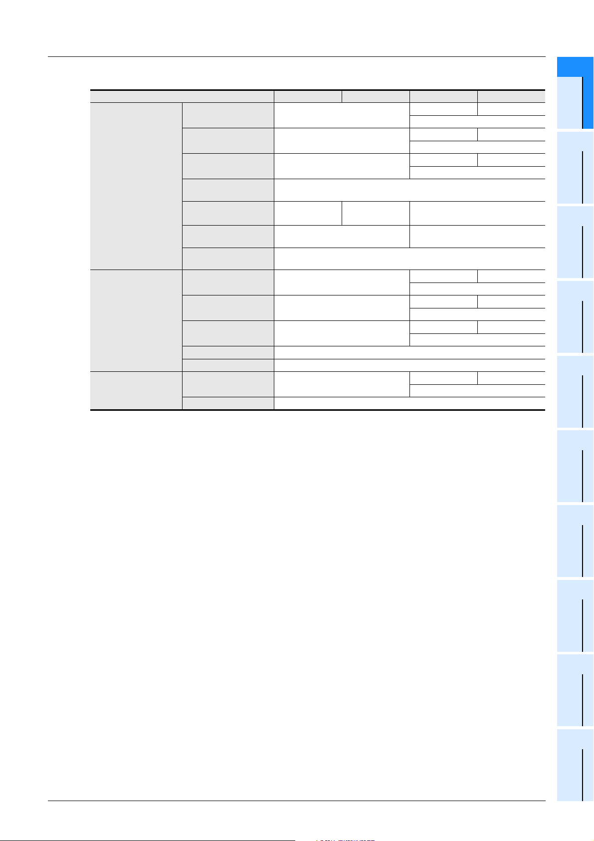
3) Types of bit device memory
Item Power OFF Power OFF→ON STOP→RUN RUN→STOP
Input relay (X) Cleared.
Output relay (Y) Cleared.
General type auxiliary
relay (M)
Contact image memory
(X, Y, M, S)
Timer contact
Time counting coil
Reset coil (T)
Counter contact
Counting coil
Reset coil (C)
Latched (backed-up) type
auxiliary relay (M)
Special auxiliary relay (M) Cleared.
General type state relay
(S)
Latched (backed-up) type
state relay (S)
For 100 ms Cleared.
For 10 ms Cleared.
For 1 ms Cleared.
Retentive type for 100 ms Does not change.
Retentive type for 1 ms Does not change.
General type Cleared.
Latched (backed-up) type Does not change.
1 Device Outline
1.2 Program Memory and Devices
Does not change. Cleared.
Does not change while M8033 is ON.
Does not change. Cleared.
Does not change while M8033 is ON.
Cleared.
Does not change.
Set to initial
*1
value.
Cleared. Does not change.
Does not change.
Does not change. Cleared.
Does not change while M8033 is ON.
Does not change.
Does not change. Cleared.
Does not change while M8033 is ON.
Does not change. Cleared.
Does not change while M8033 is ON.
Does not change. Cleared.
Does not change while M8033 is ON.
Does not change. Cleared.
Does not change while M8033 is ON.
1
Device Outline
2
Devices in
Detail
*1
Constant
3
Specified the
Device &
4
Special Device
5
Errors
*1. Some devices are cleared when the PLC mode switches from STOP to RUN.
→ For special data registers, refer to Chapter 4.
6
Types and
Setting of
Parameters
7
Other Functions
27
Page 30
FXCPU Structured Programming Manual
[Device & Common]
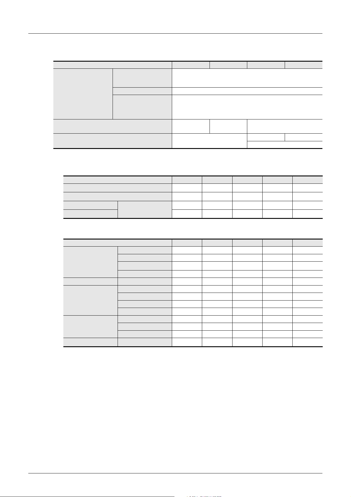
4. FX1S/FX1N/FX2N/FX1NC/FX2NC PLCs
The memory type varies depending on the PLC, and is classified as follows by the device initialization timing.
Classification Power OFF Power OFF→ON STOP→RUN RUN→STOP
A1: Backed up by battery
A: Latched type memory
B: Special device and index memory Cleared.
C: Non-latched type memory Cleared.
*1. Some devices are cleared when the PLC mode switches from STOP to RUN.
1) Types of program memory
Parameter A2 A2
Sequence program A2 A2
Comment
File register A2 A2
A2: Backed up by EEPROM Does not change.
A3: Backed up by capacitor
Item FX1S FX1N FX2N FX1NC FX2NC
Can be secured by
parameter setting.
1 Device Outline
1.2 Program Memory and Devices
(The device status is not held correctly when the battery voltage becomes
(The device status is held correctly for 10 days (when the ambient tempera-
ture is 25°C) after the capacitor is fully charged, but the device status is not
held correctly after the capacitor is discharged.)
A2 A2
Does not change.
lower than the holding voltage.)
Does not change.
Set to initial
*1
value.
A1
A1
A1
A1
Does not change.
Does not change. Cleared.
Does not change while M8033 is ON.
*1
*1
*1
*1
A2
A2
A2
A2
*1
*1
A1
*1
A1
*1
A1
*1
A1
*1. The battery is not used when an optional EEPROM or EPROM memory is attached.
2) Types of word device memory
Item FX1S FX1N FX2N FX1NC FX2NC
General type CCCCC
Data register (D)
Index register (V and Z) V, Z BBBBB
Timer current value
register (T)
Counter current value
register (C)
Clock data Current value A3A3A1A3
*1. Attach a memory board having the clock function when the clock function is required in the FX
Latched (backed-up) type A2 A2/A3 A1 A2/A3 A1
*1
File type
Special type B B B B B
For 100 ms CCCCC
For 10 ms CCCCC
Retentive type for 100 ms - A3 A1 A3 A1
Retentive type for 1 ms - A3 A1 A3 A1
General type CCCCC
Latched (backed-up) type A2 A2/A3 A1 A2/A3 A1
High speed type A2 A2 A1 A2 A1
A2 A2 A1 A2 A1
A1
2NC
Series.
*1
28
Page 31
FXCPU Structured Programming Manual
[Device & Common]
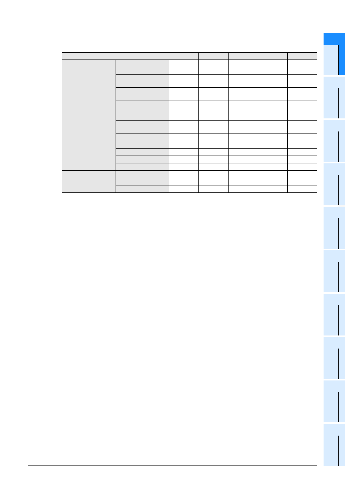
3) Types of bit device memory
Item FX1S FX1N FX2N FX1NC FX2NC
Input relay (X) CCCCC
Output relay (Y) CCCCC
General type auxiliary
relay (M)
Latched (backed-up) type
Contact image memory
(X, Y, M, S)
Timer contact
Time counting coil
Reset coil (T)
Counter contact
Counting coil
Reset coil (C)
auxiliary relay (M)
Special auxiliary relay (M)BBBBB
General type state relay
(S)
Latched (backed-up) type
state relay (S)
Annunciator (S) - - A1 - A1
For 100 ms CCCCC
For 10 ms CCCCC
Retentive type for 100 ms - A3 A1 A3 A1
Retentive type for 1 ms - A3 A1 A3 A1
General type CCCCC
Latched (backed-up) type A2 A2/A3 A1 A2/A3 A1
High speed type A2 A2 A1 A2 A1
1 Device Outline
1.2 Program Memory and Devices
CCCCC
A2 A2/A3 A1 A2/A3 A1
A2 A2/A3 C A2/A3 C
A2 A2/A3 A1 A2/A3 A1
Constant
1
Device Outline
2
Devices in
Detail
3
Specified the
Device &
4
Special Device
5
Errors
6
Types and
Setting of
Parameters
7
Other Functions
29
Page 32
FXCPU Structured Programming Manual
[Device & Common]
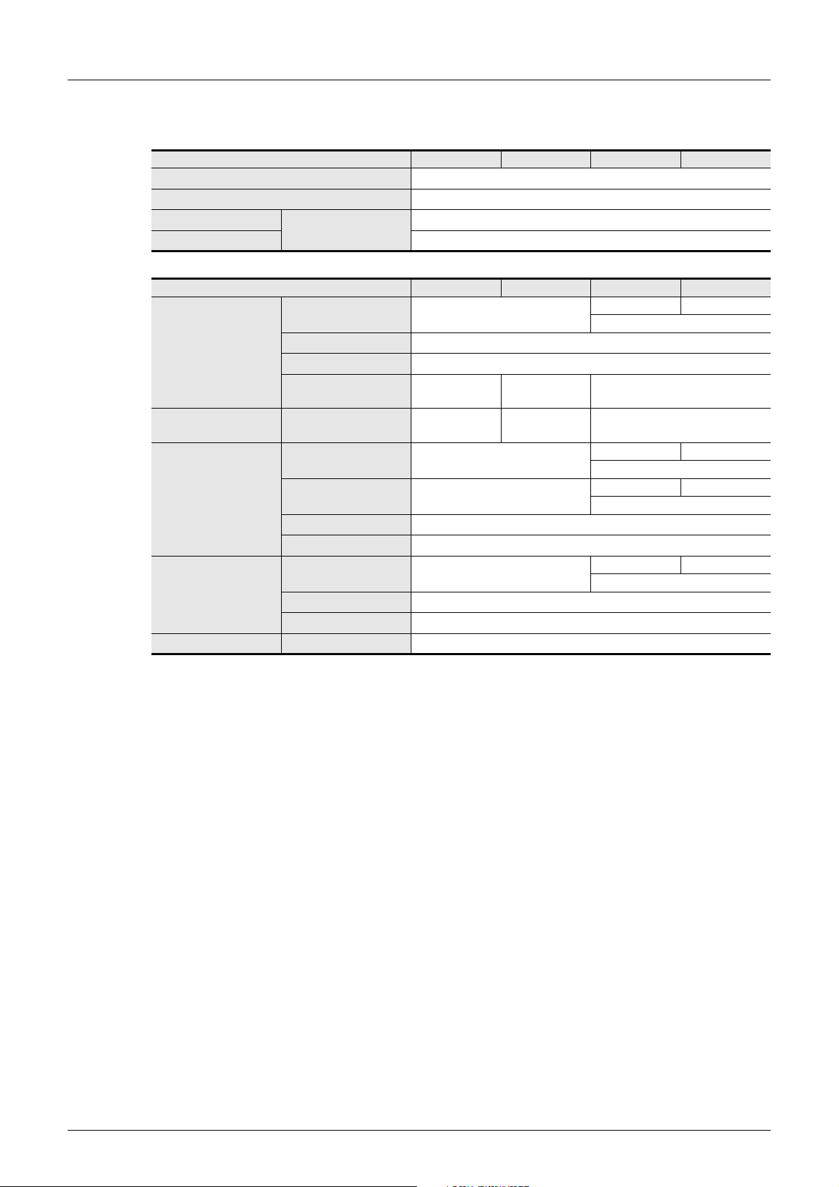
5. FX0S/FX0/FX0N/FXU/FX2C PLCs
1) Types of program memory
Item Power OFF Power OFF→ON STOP→RUN RUN→STOP
Parameter
Sequence program
Comment
File register
2) Types of word device memory
Data register (D)
Index register (V and Z) V, Z Cleared.
Timer current value
register (T)
Counter current value
register (C)
Clock data Current value
Can be secured by
parameter setting.
Item Power OFF Power OFF→ON STOP→RUN RUN→STOP
General type
Latched (backed-up) type
File type
Special type Cleared.
For 100 ms Cleared.
For 10 ms Cleared.
Retentive type for 100 ms
Retentive type for 1 ms
General type Cleared.
Latched (backed-up) type
High speed type
Cleared.
Does not change.
Does not change.
Does not change.
Does not change.
Does not change.
Does not change*2.
Set to initial
*1
value.
Set to initial
*1
value.
Does not change.
Does not change.
Does not change.
Does not change.
Does not change.
1 Device Outline
1.2 Program Memory and Devices
*2
*2
*2
*2
Does not change. Cleared.
Does not change while M8033 is ON.
*2
Does not change.
Does not change.
Does not change. Cleared.
Does not change while M8033 is ON.
Does not change. Cleared.
Does not change while M8033 is ON.
*2
*2
Does not change. Cleared.
Does not change while M8033 is ON.
*2
*2
*2
*1
*1
*1. Some devices are cleared when the PLC mode switches from STOP to RUN.
M8074 is backed up against power interruption.
*2. The device status is not held correctly when the battery voltage becomes lower than the holding
voltage.
U/FX2C PLCs)
(FX
30
Page 33
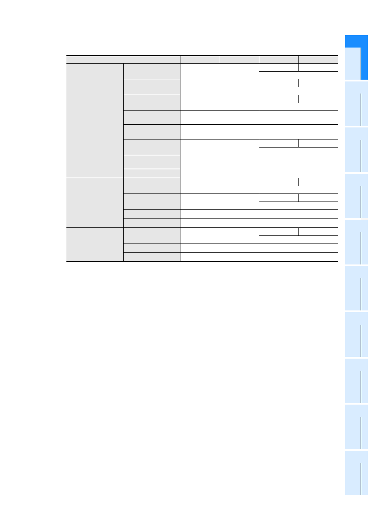
FXCPU Structured Programming Manual
[Device & Common]
3) Types of bit device memory
Item Power OFF Power OFF→ON STOP→RUN RUN→STOP
Input relay (X) Cleared.
Output relay (Y) Cleared.
General type auxiliary
relay (M)
Contact image memory
(X, Y, M, S)
Timer contact
Time counting coil
Reset coil (T)
Counter contact
Counting coil
Reset coil (C)
Latched (backed-up) type
auxiliary relay (M)
Special auxiliary relay (M) Cleared.
General type state relay
(S)
Latched (backed-up) type
state relay (S)
Annunciator (S)
For 100 ms Cleared.
For 10 ms Cleared.
Retentive type for 100 ms
Retentive type for 1 ms
General type Cleared.
Latched (backed-up) type
High speed type
Cleared.
Cleared.
Does not change.
Set to initial
*1
value.
Does not change.
Does not change.
Does not change.
Does not change.
Does not change.
Does not change.
1 Device Outline
1.2 Program Memory and Devices
Does not change. Cleared.
Does not change while M8033 is ON.
Does not change. Cleared.
Does not change while M8033 is ON.
Does not change. Cleared.
Does not change while M8033 is ON.
*2
Does not change.
Does not change. Cleared.
Does not change while M8033 is ON.
*2
*2
Does not change. Cleared.
Does not change while M8033 is ON.
Does not change. Cleared.
Does not change while M8033 is ON.
*2
*2
Does not change. Cleared.
Does not change while M8033 is ON.
*2
*2
*1
Constant
1
Device Outline
2
Devices in
Detail
3
Specified the
Device &
4
Special Device
5
Errors
*1. Some devices are cleared when the PLC mode switches from STOP to RUN.
M8074 is backed up against power interruption.
*2. The device status is not held correctly when the battery voltage becomes lower than the holding
voltage.
U/FX2C PLCs)
(FX
6
Types and
Setting of
Parameters
7
Other Functions
31
Page 34
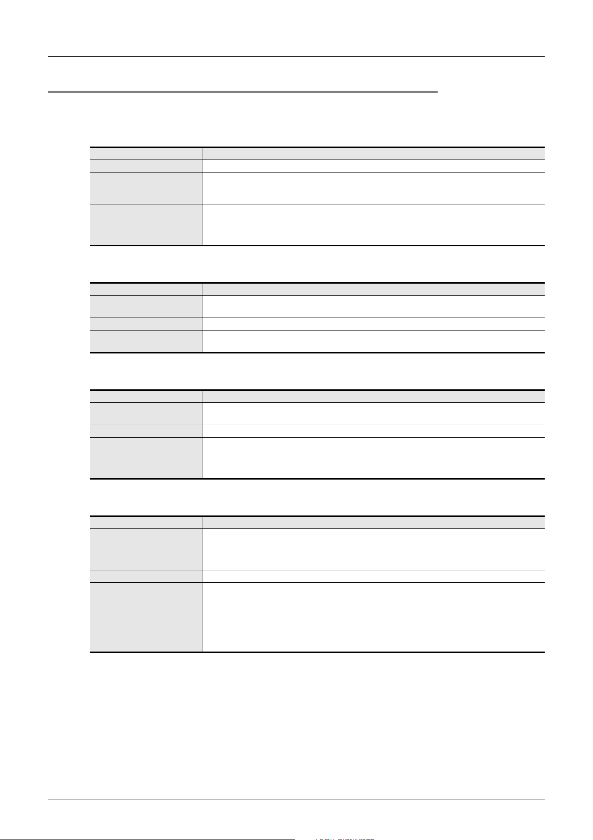
FXCPU Structured Programming Manual
[Device & Common]
1.2.3 Types of backup methods against power interruption
There are following types of latch (backup) of the program memory and built-in devices in PLCs.
1. Battery backup method
FX
U/FX2C/FX2N/FX2NC/FX3G/FX3GC/FX3U/FX3UC PLCs
Item Description
Latched (backed-up) contents A battery backs up the built-in RAM memory, latched type devices and clock data.
Maintenance
Cautions
2. Flash memory backup method
3U/FX3UC PLCs
FX
Item Description
Latched (backed-up) contents
Maintenance Maintenance is not required.
Cautions
Periodical replacement is required.
For rough guide to the replacement frequency, refer to the User's Manual [Hardware Edition] of each
PLC.
1) When the battery voltage becomes low, sequence programs and other latched (backed-up)
contents are lost.
2) When an optional memory cassette (flash memory) is attached, it is not necessary to back up
sequence programs using the battery (in FX3U/FX3UC PLCs).
1) The flash memory built in a memory cassette holds sequence programs.
2) A battery is used also to hold latched (backed-up) type devices and clock data.
The upper limit is set for the number of times of overwriting.
(Refer to the User's Manual [Hardware Edition] of each PLC.)
1 Device Outline
1.2 Program Memory and Devices
3. EEPROM backup method
FX0S/FX0N/FX1S/FX1N/FX1NC/FX3S/FX3G/FX3GC PLCs
Item Description
Latched (backed-up) contents
Maintenance Maintenance is not required.
Cautions
1) The EEPROM built in the PLC holds sequence programs and latched (backed-up) type devices.
2) A capacitor is used also to hold the clock data.
1) The upper limit is set for the number of times of overwriting.
(Refer to the User's Manual [Hardware Edition] of each PLC.)
2) For secure backup, it is necessary to keep the PLC power ON for 5 minutes or more, and then turn
OFF the power.
4. Capacitor backup method
1N/FX1NC PLCs
FX
Item Description
1) The large-capacity capacitor built in the PLC holds latched (backed-up) type devices and clock
Latched (backed-up) contents
Maintenance Maintenance is not required.
Cautions
data.
2) The capacitor holds data for 10 days (when the ambient temperature is 25°C) if it is fully charged
as described below.
1) The large-capacity capacitor is charged while the PLC is ON, and fully charged after the PLC is
ON for 30 minutes or more.
2) When the voltage of the large-capacity capacitor becomes low, latched (backed-up) type devices
are not held correctly.
When using the PLC for the first time after purchase, or when using the PLC after power OFF for a
long time (10 days [when the ambient temperature is 25°C] in the fully charged status), clear
latched (backed-up) type devices.
32
Page 35
FXCPU Structured Programming Manual
[Device & Common]
1.2 Program Memory and Devices
1.2.4 Change of devices between general type and latched (backed-up) type
FX0S/FX0/FX0N/FX1S/FX1N/FX1NC/FX3S/FX3G*1/FX3GC*1 PLCs do not support the type change of latched
(backed-up) type devices.
1 Device Outline
1
Device Outline
1. When using latched (backed-up) type devices as non-latched type devices
Some latched (backed-up) type devices can be changed into the non-latched type by parameter setting.
Devices dedicated to the latched type cannot be changed into the non-latched type.
Such devices can be handled as non-latched type devices by clearing all latched type devices using the initial
pulse (M8002) in a program.
2. When using non-latched type devices as latched (backed-up) type devices
Non-latched type devices can be changed into the latched (backed-up) type by parameter setting.
*1. In FX
3G/FX3GC PLCs, non-latched type devices can be changed into the latched (backed-up) type by
selecting the battery mode using a parameter if an optional battery is attached.
1.2.5 How to initialize latched (backed-up) type devices
Latched (backed-up) type devices can be initialized by clearing the whole PLC memory using peripheral
equipment, clearing all latched type memories using the special auxiliary relay M8032, or executing the ZRST
instruction.
This subsection describes two major methods.
1. M8032 (latched type memory all clear)
When M8032 is set to ON, all latched (backed-up) devices*1 (including reset coils of timers and counters) are
cleared.
M8032 can be set to ON and OFF using the forced ON/OFF operation from peripheral equipment or in a
sequence program. Note that latched type devices cannot be set to ON while M8032 is ON.
When M8032 is set to ON in a program, note that latched type devices are cleared during execution of the
END instruction after M8032 turns ON.
Program example:
This program clears all latched type devices.
Constant
Parameters
2
Devices in
Detail
3
Specified the
Device &
4
Special Device
5
Errors
6
Types and
Setting of
M8002
M8032
Initial pulse
→ For details, refer to Subsection 4.2.11.
*1. General type devices which have been changed into the latched type in the FX
an optional battery attached are also cleared.
3G/FX3GC PLCs using
7
Other Functions
33
Page 36
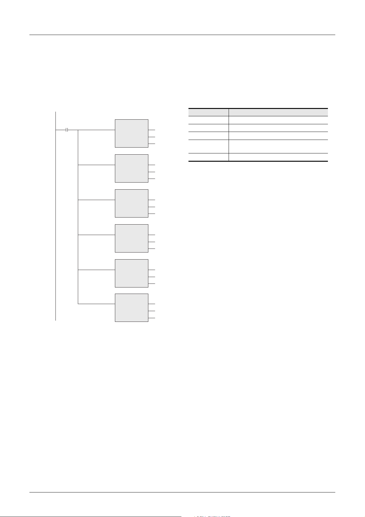
FXCPU Structured Programming Manual
[Device & Common]
2. ZRST instruction (zone reset)
The ZRST instruction can clear multiple devices all at once.
(Because only a limited device range can be specified for the ZRST instruction, only a part of latched type
devices can be cleared at a time.)
Program example:
This program clears latched (battery backed-up) type devices in the ranges shown in the table below in the
FX
3U and FX3UC PLCs.
Clear input
ZRST
EN ENO
d1
d2
ZRST
EN ENO
d1
d2
ZRST
EN ENO
d1
d2
M500
M7679
S500
S4095
T246
T255
1.2 Program Memory and Devices
Latched (backed-up) device range
Auxiliary relay M500 to M7679
State relay S500 to S4095
Timer T246 to T255
Counter
Data register D200 to D7999
C100 to C199,
C220 to C255
1 Device Outline
ZRST
EN ENO
d1
C100
d2
C199
ZRST
EN ENO
d1
C220
d2
C255
ZRST
EN ENO
d1
D200
d2
D7999
→ For details on latched (backed-up) type devices, refer to Subsection 1.2.2
34
Page 37
FXCPU Structured Programming Manual
[Device & Common]
2. Devices in Detail
2 Devices in Detail
2.1 Device Number List
1
Device Outline
This chapter explains how numeric values are handled in the PLC as well as the roles and functions of
various built-in devices including I/O relays, auxiliary relays, state relays, counters and data registers.
The following contents provide a basis for handling the PLC.
2.1 Device Number List
Device numbers are assigned in the FX3U and FX3UC PLCs as shown below.
The assignment varies depending on each PLC. For details, refer to the reference section.
For input relay numbers and output relay numbers when I/O extension equipment and special extension
equipment are connected to the PLC main unit, refer to the User's Manual [Hardware Edition] of each PLC.
Device name Description Reference
I/O relay
Input relay X000 to X367 248 points
Output relay Y000 to Y367 248 points
Auxiliary relay
General type [changeable] M0 to M499 500 points
Latched (backed-up) type
[changeable]
Latched (backed-up) type [fixed] M1024 to M7679 6656 points
Special type
State relay
Initial state
(General type [changeable])
General type [changeable] S10 to S499 490 points
Latched (backed-up) type
[changeable]
Annunciator
(Latched (backed-up) type
[changeable])
Latched (backed-up) type [fixed] S1000 to S4095 3096 points
Timer (on-delay timer)
100 ms T0 to T191 192 points 0.1 to 3276.7 sec
100 ms
[for subroutine or interrupt routine]
10 ms T200 to T245 46 points 0.01 to 327.67 sec
Retentive type for 1 ms T246 to T249 4 points 0.001 to 32.767 sec
Retentive type for 100 ms T250 to T255 6 points 0.1 to 3276.7 sec
1 ms T256 to T511 256 points 0.001 to 32.767 sec
Counter
General type up-counter (16 bits)
[changeable]
Latched (backed-up) type upcounter (16 bits) [changeable]
General type bidirectional counter
(32 bits) [changeable]
Latched (backed-up) type
bidirectional counter (32 bits)
[changeable]
*2
Device numbers are octal.
The total number of inputs and outputs is 256.
Devices can be changed between the latched
M500 to M1023 524 points
M8000 to M8511 512 points Chapter 4
S0 to S9 10 points
S500 to S899 400 points
S900 to S999 100 points
T192 to T199 8 points 0.1 to 3276.7 sec
C0 to C99 100 points
C100 to C199 100 points
C200 to C219 20 points
C220 to C234 15 points
(backed-up) type and the non-latched type using
parameters.
Devices can be changed between the latched
(backed-up) type and the non-latched type using
parameters.
0 to 32767 counts
Devices can be changed between the latched
(backed-up) type and the non-latched type using
parameters.
-2147483648 to +2147483647 counts
Devices can be changed between the latched
(backed-up) type and the non-latched type using
parameters.
Section 2.2
Section 2.3
Section 2.4
Section 2.5
Section 2.6
2
Devices in
Detail
3
Specified the
Device &
Constant
4
Special Device
5
Errors
6
Types and
Setting of
Parameters
7
Other Functions
35
Page 38
FXCPU Structured Programming Manual
[Device & Common]
Device name Description Reference
High speed counter
1-phase 1-counting input
Bidirectional (32 bits)
1-phase 2-counting input
Bidirectional (32 bits)
2-phase 2-counting input
Bidirectional (32 bits)
Data register (32 bits when used in pair form)
General type (16 bits)
[changeable]
Latched (backed-up) type
(16 bits) [changeable]
Latched (backed-up) type
(16 bits) [fixed] <file register>
Special type (16 bits)
Index type (16 bits)
Extension register/Extension file register
Extension register (16 bits) R0 to R32767 32768 points
Extension file register (16 bits) ER0 to ER32767 32768 points
Pointer
For JUMP or CALL branch P0 to P4095 4096 points For CJ and CALL instructions
Input interrupt
Input delay interrupt
Timer interrupt
Counter interrupt I010 to I060 6 points For HSCS instruction
Nesting
For master control N0 to N7 8 points For MC instruction
Constant
Decimal (K)
Hexadecimal (H)
Real number (E) 32 bits
Character string ("") Character string
*2
C235 to C245
C246 to C250
C251 to C255
D0 to D199 200 points
D200 to D511 312 points
D512 to D7999
<D1000 to D7999>
D8000 to D8511 512 points Chapter 4
V0 to V7, Z0 to Z7
I0 to I5
I6 to I8
16 bits -32,768 to +32,767
32 bits -2,147,483,648 to +2,147,483,647
16 bits 0 to FFFF
32 bits 0 to FFFFFFFF
2 Devices in Detail
2.1 Device Number List
Up to 8 points can be used among C235 to C255 [latched
(backed-up) type]
The setting can be changed between the latched (backed-up) type
and the non-latched type using parameters.
-2,147,483,648 to +2,147,483,647 counts
Hardware counter
1 phase : 100 kHz × 6 points, 10 kHz × 2 points
2 phases : 50 kHz (1-edge counting), 50 kHz (4-edge counting)
Software counter
1 phase : 40 kHz
2 phases : 40 kHz (1-edge counting), 10 kHz (4-edge counting)
7488 points
<7000 points>
16 points Section 2.10
6 points
3 points
128
-1.0 × 2
Both the decimal point expression and the exponent expression
are available.
Specify characters with quotation marks.
In a constant of an instruction, up to 32 half-width characters are
available.
*1
The setting can be changed between the
latched (backed-up) type and the non-latched
type using parameters.
Among 7488 fixed latched (backed-up) type
data registers, D1000 and later can be set as file
registers in units of 500 points using
parameters.
Backed up by a battery against power
interruption.
Available only while a memory cassette is
attached.
to -1.0 × 2
-126
, 0, 1.0 × 2
-126
to 1.0 × 2
128
Section 2.7
Section 2.8
Section 2.9
Section 2.11
Chapter 3
36
*1. When the FX3U-4HSX-ADP is connected to an FX3U PLC, the maximum input frequency is set as
follows:
1 phase : 200 kHz
2 phases : 100 kHz (1-edge counting), 100 kHz (4-edge counting)
*2. For supported functions, refer to Chapter 4.
For handling of the latched (backed-up) area, refer to Section 1.2.
Page 39
FXCPU Structured Programming Manual
[Device & Common]
2.2 Input/Output Relays [X and Y]
Some input relay and output relay numbers are secured in the main unit, and others are assigned to
extension equipment according to the connection order.
Because input/output relays are numbered in octal, numeric values such as "8" and "9" do not exist.
2.2.1 Numbers of input/output relays
The tables below show input relay (X) and output relay (Y) numbers. (Numbers are assigned in octal.)
1. FX3S/FX3G/FX3GC/FX3U/FX3UC PLCs
2 Devices in Detail
2.2 Input/Output Relays [X and Y]
1
Device Outline
2
Devices in
Detail
Model name FX3U-16M FX3U-32M FX3U-48M FX3U-64M FX3U-80M FX3U-128M When extended
FX3U PLC
FX3UC (D, DS, DSS)
PLC
FX3UC-32MTLT(-2) PLC
FX3G PLC
FX3GC PLC
Input
Output
Model name FX3UC-32MT-LT(-2) When extended
Model name FX3G-14M FX3G-24M FX3G-40M FX3G-60M When extended
Input
Output
Model name FX
X000 to X007
8 points
Y000 to Y007
8 points
Model name FX3UC-16M FX3UC-32M FX3UC-64M FX3UC-96M When extended
Input
Output
Input
Output
X000 to X007
8 points
Y000 to Y005
6 points (8)
Input
Output
X000 to X017
16 points
Y000 to Y017
16 points
X000 to X007
8 points
Y000 to Y007
8 points
X000 to X017
16 points
Y000 to Y017
16 points
X000 to X015
14
Y000 to Y011
*1
10
3GC-32MT/D(DSS) When extended
X000 to X017
16 points
Y000 to Y017
16 points
points
points
X000 to X027
24 points
Y000 to Y027
24 points
X000 to X017
16 points
Y000 to Y017
16 points
X000 to X357
240 points
Y000 to Y357
240 points
X000 to X027
*1
(16)
(16)
24 points
Y000 to Y017
*1
16 points
X000 to X177
128 points
Y000 to Y177
128 points
X000 to X037
32 points
Y000 to Y037
32 points
X000 to X037
32 points
Y000 to Y037
32 points
X000 to X047
40 points
Y000 to Y047
40 points
X000 to X057
48 points
Y000 to Y057
48 points
256
points
in total
X000 to X043
36
points
Y000 to Y027
24 points
128
points
in total
(40)
X000 to X177
*1
128 points
Y000 to Y177
128 points
X000 to X077
64 points
Y000 to Y077
64 points
X000 to X367
248 points
Y000 to Y367
248 points
X000 to X367
248 points
Y000 to Y367
248 points
256
points
in total
128
points
in total
256
points
in total
3
Specified the
Device &
Constant
4
Special Device
5
Errors
6
Types and
Setting of
Parameters
7
Other Functions
Model name FX3S-10M FX3S-14M FX3S-20M FX3S-30M
FX3S PLC
Input
Output
X000 to X005
6 points
Y000 to Y003
4 points
X000 to X007
8 points
Y000 to Y005
6 points
X000 to X013
12 points
Y000 to Y007
8 points
X000 to X017
16 points
Y000 to Y015
14 points
*1. A number inside ( ) indicates the number of occupied points.
The difference from the number of effective points indicates unused numbers.
No
extension
37
Page 40
FXCPU Structured Programming Manual
[Device & Common]
2. FX1S/FX1N/FX1NC/FX2N/FX2NC PLCs
Model name FX1S-10M FX1S-14M FX1S-20M FX1S-30M
FX1S PLC
FX1N PLC
FX2N PLC
FX1NC
PLC
Input
Output
Model name FX1N-24M FX1N-40M FX1N-60M When extended
Input
Output
Model name FX2N-16M FX2N-32M FX2N-48M FX2N-64M FX2N-80M FX2N-128M When extended
Input
Output
Model name FX1NC-16M FX1NC-32M When extended
Input
Output
X00 to X05
6 points
Y00 to Y03
4 points
X000 to X015
14 points
Y000 to Y011
10 points
X000 to X007
8 points
Y000 to Y007
8 points
X000 to X007
8 points
Y000 to Y007
8 points
X000 to X017
16 points
Y000 to Y017
16 points
X000 to X017
16 points
Y000 to Y017
16 points
X00 to X07
8 points
Y00 to Y05
6 points
X000 to X027
24 points
Y000 to Y017
16 points
X000 to X027
24 points
Y000 to Y027
24 points
X00 to X013
12 points
Y00 to Y07
8 points
X000 to X043
36 points
Y000 to Y027
24 points
X000 to X037
32 points
Y000 to Y037
32 points
X000 to X177
128 points
Y000 to Y177
128 points
X00 to X17
16 points
Y00 to Y15
14 points
X000 to X177
128 points
Y000 to Y177
128 points
X000 to X047
40 points
Y000 to Y077
40 points
128
points
in total
2 Devices in Detail
2.2 Input/Output Relays [X and Y]
No
extension
128
points
in total
X000 to X077
64 points
Y000 to Y077
64 points
X000 to X267
184 points
Y000 to Y267
184 points
256
points
in total
Model name FX2NC-16M FX2NC-32M FX2NC-64M FX2NC-96M When extended
FX2NC
PLC
0S/FX0/FX0N/FXU/FX2C PLCs
3. FX
FX0S/FX0
PLC
FX0N PLC
FXU PLC
Input
Output
Model name FX0S-10M FX0/FX0S-14M FX0/FX0S-20M FX0/FX0S-30M
Input
Output
Model name FX
Input
Output
Model name FXU-16M FXU-24M FXU-32M FXU-48M FXU-64M FXU-80M FXU-128M
Input
Output
X000 to X007
8 points
Y000 to Y007
8 points
X000 to X005
6 points
Y000 toY003
4 points
0N-24M FX0N-40M FX0N-60M When extended
X000 to X015
14 points
Y000 to Y011
10 points
X000 to X007
8 points
Y000 to Y007
8 points
X000 to X017
16 points
Y000 to Y017
16 points
X000 to X007
8 points
Y000 to Y005
6 points
X000 to X027
24 points
Y000 to Y017
16 points
X000 to X013
12 points
Y000 to Y013
12 points
X000 to X037
32 points
Y000 to Y037
32 points
X000 to X013
Y000 to Y007
X000 to X043
Y000 to Y027
X000 to X017
16 points
Y000 to Y017
16 points
X000 to X057
48 points
Y000 to Y057
48 points
12 points
8 points
36 points
24 points
X000 to X027
Y000 to Y027
24 points
24 points
X000 to X267
184 points
Y000 to Y267
184 points
X000 to X017
16 points
Y000 to Y015
14 points
X000 to X127
84 points
Y000 to Y77
64 points
X000 to X037
32 points
Y000 to Y037
32 points
points
in total
No
extension
128
points
in total
X000 to X047
Y000 to Y047
256
40 points
40 points
X000 to X077
64 points
Y000 to Y077
64 points
38
FXU PLC
FX2C PLC
Model name When extended
Input
Output
X000 to X267
184 points
Y000 to Y267
184 points
2C-64M FX2C-96M FX2C-128M FX2C-160M When extended
X000 to X037
32 points
Y000 to Y037
32 points
Input
Output
Model name FX
256
points
in total
X000 to X057
48 points
Y000 to Y057
48 points
X000 to X077
64 points
Y000 to Y077
64 points
X000 to X117
80 points
Y000 to Y117
80 points
X000 to X267
184 points
Y000 to Y267
184 points
256
points
in total
Page 41
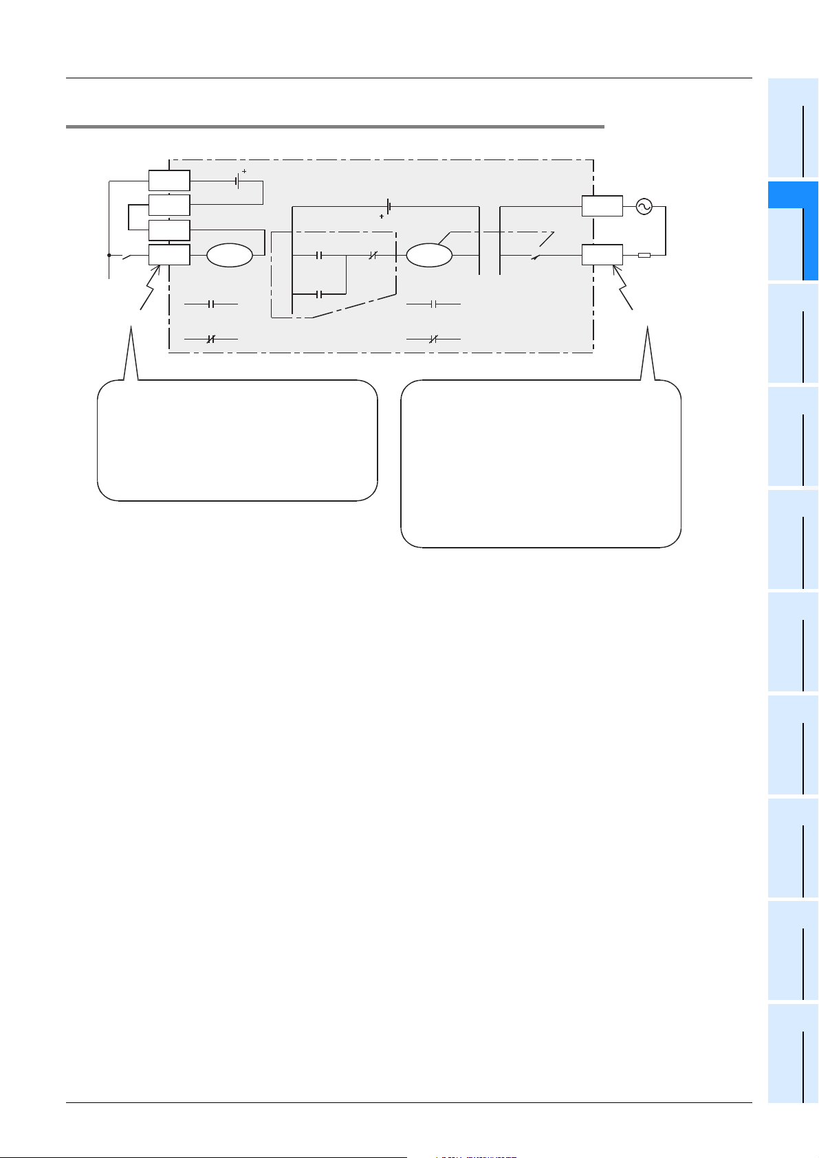
FXCPU Structured Programming Manual
[Device & Common]
2.2.2 Functions and roles
Examples of terminal names and wiring (sink input) are for the FX3U Series PLC.
2 Devices in Detail
2.2 Input/Output Relays [X and Y]
1
Device Outline
0V
24V
S/S
Input
X000
signal
Input terminal
The PLC receives signals from external switches
through input terminals.
An input relay (X) connected to an input terminal
inside the PLC is an electronic relay isolated
optically, and has many normally-open (NO)
contacts and normally-closed (NC) contacts.
These contacts can be arbitrarily used inside the PLC.
These input relays cannot be driven by programs.
X000
X000
X000
Program example
X000
Y000
PLC
X001
External power supply
COM1
Y000
Y000
NO contact
Y000
NC contact
The PLC outputs signals to external loads through
output terminals. Contacts for external output
(output devices such as relay contacts, TRIACs and
transistors) of output relays are connected to output
terminals inside the PLC.
An output relay has many NO contacts and NC
contacts.
These contacts can be arbitrarily used inside the PLC.
Differences in operations between external output
contacts (output devices) and internal contacts
are explained on the next page.
Y000
Load
Output terminal
Constant
2
Devices in
Detail
3
Specified the
Device &
4
Special Device
5
Errors
6
Types and
Setting of
Parameters
7
Other Functions
39
Page 42
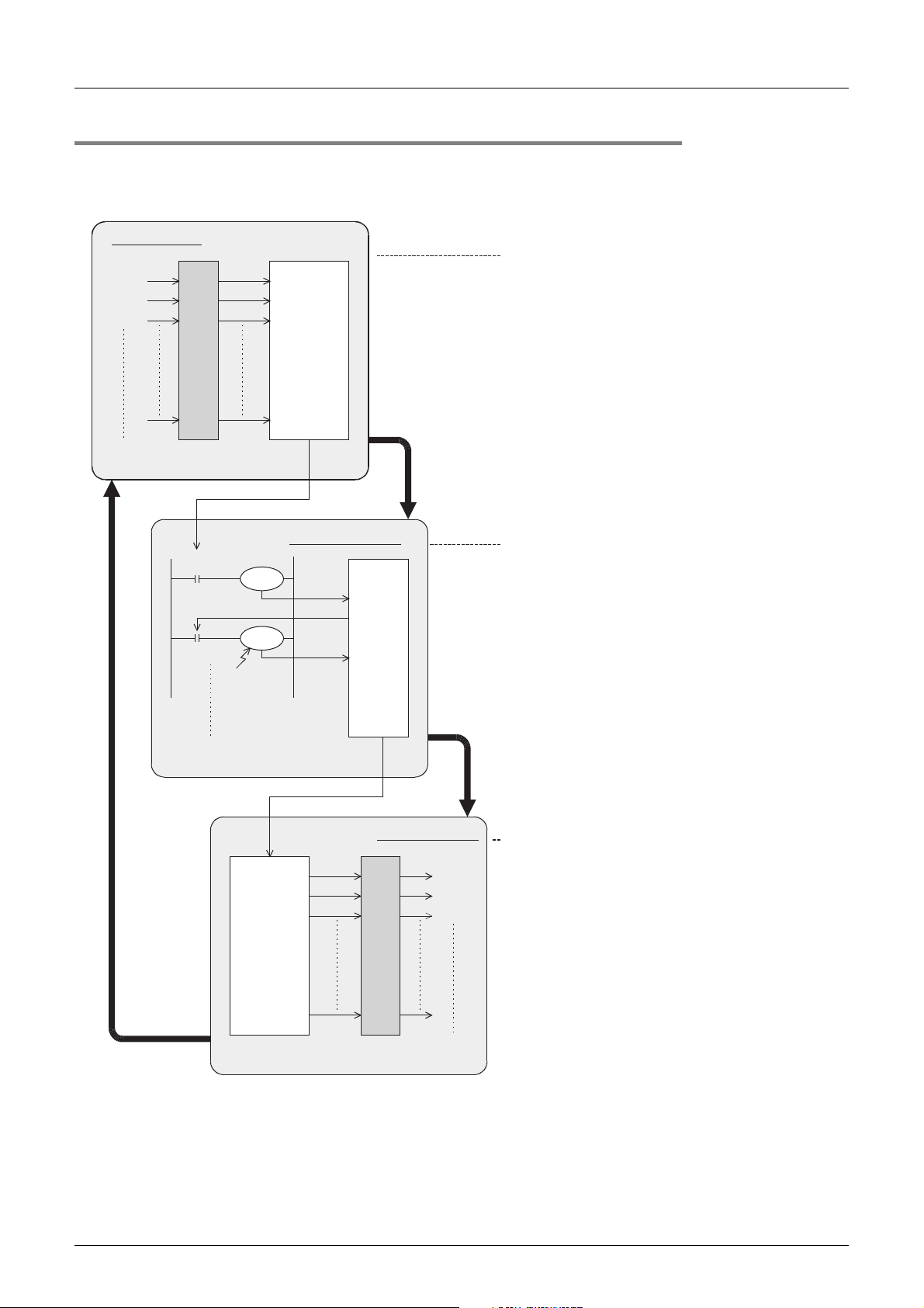
FXCPU Structured Programming Manual
[Device & Common]
2.2.3 Operation timing of I/O relays
The PLC executes sequence control by repeatedly executing the following processing procedure.
In this batch I/O method, not only are there driving times of input filters and output devices but also response
delays caused by operation cycles.
2 Devices in Detail
2.2 Input/Output Relays [X and Y]
Input processing
X000
X001
X002
X000
Y000
1)
Read-in
Input terminal
2) Read-out
Y000
M 0
Auxiliary relay
Input
image
memory
Program processing
3) Write
4) Read
-out
5) Write
Device
image
memory
1) 2) 3)...6) indicate the processing order.
Input processing
Before executing a program, the PLC reads the
ON/OFF status of all input terminals inside the
PLC into the input image memory.
Even if inputs change while the PLC is executing
the program, the contents of the input image
memory remain unchanged, but the changes in inputs
are read during the input processing in the next cycle.
Even if an input contact changes from ON to OFF or
from OFF to ON, its ON/OFF status is judged after the
response delay (approximately 10 ms) caused by the
input filter.
(When the input filter is the digital type, its value
can be overwritten by a sequence program.)
Program processing
The PLC reads the ON/OFF status of each device from the
input image memory and other device image memories
according to the contents of instructions in the program
memory, executes operations in sequence from the step 0,
and then writes the operation result to the image memory
at each time.
Accordingly, the contents of the image memory of each
device change as the program is executed.
The operation of a contact inside an output relay is
determined by the contents of the output image memory.
Repeated
operation
[The time
required for a
cyclic operation
is called
operation cycle
(scan time).]
The above method is called the batch I/O method (or refresh method).
6) Output
Output
latch
memory
Output processing
Output terminal
40
Y000
Y001
Y002
Output processing
When execution of all instructions is finished, the ON/OFF
status of the image memory of outputs (Y) is transferred to
the latch memory. This is the actual output of the PLC.
External output contacts inside the PLC operate after the
response delay time of the output devices.
Page 43
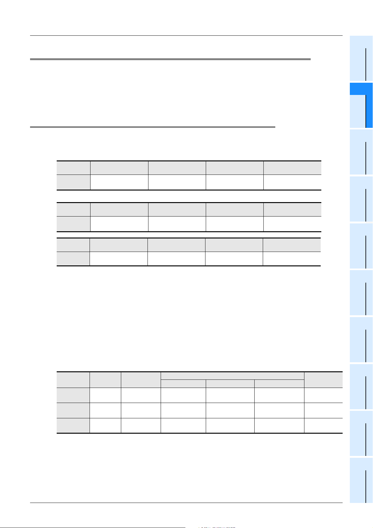
FXCPU Structured Programming Manual
[Device & Common]
2.3 Auxiliary relay [M]
There are many auxiliary relays inside the PLC. Coils of auxiliary relays are driven by contacts of various
devices inside the PLC in the same way as output relays.
Auxiliary relays have many electronically normally-open contacts and normally-closed contacts which can be
used arbitrarily inside the PLC.
However, external loads cannot be driven directly by these contacts. External loads should be driven by
output relays.
2.3.1 Numbers of auxiliary relays
2 Devices in Detail
2.3 Auxiliary relay [M]
1
Device Outline
2
Devices in
Detail
The table below shows auxiliary relay (M) numbers. (Numbers are assigned in decimal.)
1. FX3S/FX3G/FX3GC/FX3U/FX3UC PLCs
Latched (battery
backed-up) type
M500 to M1023
524 points
Fixed latched (EEPROM
backed-up) type
M384 to M1535
1152 points
Fixed latched (EEPROM
backed-up) type
M384 to M511
128 points
*2
FX3U/FX3UC
PLC
FX3G/FX3GC
PLC
FX3S PLC
General type
M0 to M499
500 points
General type
M0 to M383
384 points
General type
M0 to M383
384 points
*1
*1. This area is not latched (backed up). It can be changed to the latched (backed-up) area by parameter
setting.
*2. This area is latched (backed up). It can be changed to the non-latched (non-backed-up) area by
parameter setting.
*3. The characteristics of latch (backup) cannot be changed using parameters.
*4. They can be changed to the latched (battery backed-up) type using parameters while an optional
battery is attached. However, the latched area cannot be set.
When simple N:N link or parallel link is used, some auxiliary relays are occupied for the link.
Fixed latched (battery
backed-up) type
M1024 to M7679
6656 points
General type Special type
M1536 to M7679
6144 points
General type Special type
M512 to M1535
1024 points
*3
*4
Special type
M8000 to M8511
512 points
M8000 to M8511
512 points
M8000 to M8511
512 points
→ Refer to the data communication manual.
3
Specified the
Device &
Constant
4
Special Device
5
Errors
6
Types and
Setting of
Parameters
7
Other Functions
2. FX1S/FX1N/FX1NC/FX2N/FX2NC PLCs
Fixed latched (backed-up) type
M384 to M511
128 points
M384 to M511
128 points
*3
*3
*3
--
-
M512 to M1535
1024 points
*3
Special type
M8000 to M8255
M8000 to M8255
M8000 to M8255
FX1S PLC
FX1N/FX1NC
PLC
FX2N/FX2NC
PLC
General
type
M0 to M383
384 points
M0 to M383
384 points
M0 to M499
500 points
Latched (battery
backed-up) type
*3
*3
M500 to M1023
*1
524 points
Battery backed-up EEPROM backed-up Capacitor backed-up
--
--
M1024 to M3071
*2
2048 points
*1. This area is not latched (backed up). It can be changed to the latched (backed-up) area by parameter
setting.
*2. This area is latched (backed up). It can be changed to the non-latched (non-backed-up) area by
parameter setting.
*3. The characteristics of latch (backup) cannot be changed using parameters.
256 points
256 points
256 points
41
Page 44

FXCPU Structured Programming Manual
[Device & Common]
3. FX0S/FX0/FX0N/FXU/FX2C PLCs
2 Devices in Detail
2.3 Auxiliary relay [M]
General type Latched (backed-up) type
FX0S/FX0
PLC
FX0N PLC
FXU/FX2C
PLC
FXU PLC (Ver.
2.30 or earlier)
(Reference)
M0 to M495
496 points
M0 to M383
384 points
M0 to M499
500 points
*4
*4
M500 to M1023
524 points
*1
For link
Parent → Child:M800 to M899
Child → Parent:M900 to M999
*1. This area is not latched (backed up). It can be changed to the latched (backed-up) area by parameter
setting.
*2. This area is latched (backed up). It can be changed to the non-latched (non-backed-up) area by
parameter setting.
*3. This area is fixed to the latched (backed-up) type. (The contents can be cleared by the RST and ZRST
instructions.)
*4. This area is fixed to the non-latched (non-backed-up) type. The characteristics of latch (backup)
cannot be changed.
2.3.2 Functions and operation examples
1. General type
All of general type auxiliary relays turn OFF when the PLC is turned
M100
M100
NO contact
OFF.
When the ON/OFF status of auxiliary relays just before power
interruption is required for control, use latched (backed-up) type
auxiliary relays.
Fixed latched
(backed-up) type
-
-
*2
M496 to M511
16 points
M384 to M511
128 points
M1024 to M1535
512 points
*3
*3
*3
-
Special type
M8000 to M8254
57 points
M8000 to M8254
67 points
M8000 to M8255
173 points
M8000 to M8255
169 point
M100
NC contact
Auxiliary relay circuit
42
Page 45
FXCPU Structured Programming Manual
[Device & Common]
2. Latched (backed-up) type
When the power is turned OFF while the PLC is operating, all of output relays and general type auxiliary
relays turn OFF.
Even when the power is restored after that, all of output relays and general type auxiliary relays remain OFF
except those whose input condition is ON. In some output relays and auxiliary relays, however, the ON/OFF
status just before power interruption should be stored and then replicated when the power is restored,
depending on control targets. In such a case, use latched (backed-up) type auxiliary relays.
Latched (backed-up) type devices are backed up by a battery, EEPROM, etc. built in the PLC.
→ For details on the backup method against power interruption, refer to Section 1.2.
2 Devices in Detail
2.3 Auxiliary relay [M]
1
Device Outline
2
Devices in
Detail
X000
M600
X001
M600
The left figure shows an operation example of M600
(latched type device) in a self-holding circuit.
When X000 turns ON and M600 turns ON in this circuit,
M600 holds its operation by itself even if X000 turns OFF.
Because M600 is a latched (backed-up) type device, it
Backup against power interruption
PLC
(self-holding circuit)
remains activated even when the operation is restarted
after X000 has turned OFF due to power interruption. If a
normally-closed contact of X001 is opened when the
operation is restarted, however, M600 is deactivated.
X000
EN ENO
X001
EN ENO
PLC
Backup against power interruption
(set/reset circuit)
SET
d
RST
d
The left figure shows a circuit using the SET and RST
instructions.
M600
M600
1) Application example of latched (backed-up) type auxiliary relays
Left
limit
Limit switch
LS 1(X000)
Right
limit
Limit switch
LS 2(X001)
In some cases, the table should be restarted in the same
direction as the direction selected just before power
interruption.
Constant
Parameters
3
Specified the
Device &
4
Special Device
5
Errors
6
Types and
Setting of
Table in reciprocating motion
X000
M600
X001
M600
Rightward
drive command
Motor
with brake
X000 = ON (at the left limit) → M600 = ON → The table is
driven rightward. → The power is turned OFF. → The table
stops in an intermediate position. → The table is restarted
(M600 = ON). → X001 = ON (at the right limit) → M600 =
OFF, M601 = ON → The table is driven leftward.
X001
M601
X000
M601
Leftward
drive command
2) Method to use a fixed latched (backed-up) type auxiliary relay as a general type auxiliary relay
When using a fixed latched (backed-up) type auxiliary relay as a general type auxiliary relay, provide a
reset circuit shown in the figure below around the head step in the program.
M8002
Initial pulse
ZRST
EN ENO
d1
d2
M1024
M1999
7
Other Functions
43
Page 46
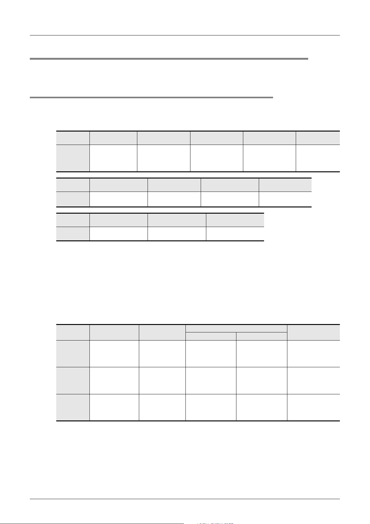
FXCPU Structured Programming Manual
[Device & Common]
2.4 State Relay [S]
State relays (S) are important devices to simply program stepping type process control, and are combined
with the step ladder instruction STL.
2.4.1 Numbers of state relays
The table below shows state relay (S) numbers. (Numbers are assigned in decimal.)
1. FX3S/FX3G/FX3GC/FX3U/FX3UC PLCs
2 Devices in Detail
2.4 State Relay [S]
FX3U/FX3UC
PLC
FX3G/FX3GC
PLC
FX3S PLC
Initial state type General type
S0 to S9
*1
10 points
Initial state (EEPROM
backed-up) type
S0 to S9
10 points
Initial state (EEPROM
backed-up) type
S0 to S9
10 points
S0 to S499
500 points
(S0 to S9 are provided
for the initial state.)
Latched (EEPROM
backed-up) type
S10 to S899
890 points
Fixed latched (EEPROM
backed-up) type
S10 to S127
118 points
*1
Latched (battery
backed-up) type
S500 to S899
400 points
Annunciator (EEPROM
*2
backed-up) type
S900 to S999
100 points
General type
S128 to S255
128 points
Fixed latched (battery
backed-up) type
S1000 to S4095
3096 points
*3
General type
S1000 to S4095
3096 points
Annunciator type
S900 to S999
100 points
*4
*1. This area is not latched (backed up). It can be changed to the latched (backed-up) area by parameter
setting.
*2. This area is latched (backed up). It can be changed to the non-latched (non-backed-up) area by
parameter setting.
*3. The characteristics of latch (backup) cannot be changed using parameters.
*4. They can be changed to the latched (battery backed-up) type using parameters while an optional
battery is attached. However, the latched area cannot be set.
2. FX1S/FX1N/FX1NC/FX2N/FX2NC PLCs
*2
44
General type
FX1S PLC - -
FX1N/FX1NC
PLC
FX2N/FX2NC
PLC
(S0 to S9 are provided
--
S0 to S499
500 points
for the initial state.)
*1
Latched (battery
backed-up) type
S500 to S899
400 points
*2
Fixed latched (backed-up) type
EEPROM backed-up Capacitor backed-up
S0 to S127
128 points
(S0 to S9 are provided
for the initial state.)
S0 to S127
128 points
(S0 to S9 are provided
for the initial state.)
*3
*3
--
--
S128 to S999
872 points
*3
Annunciator type
-
S900 to S999
100 points
*2
*1. This area is not latched (backed up). It can be changed to the latched (backed-up) area by parameter
setting.
*2. This area is latched (backed up). It can be changed to the non-latched (non-backed-up) area by
parameter setting.
*3. The characteristics of latch (backup) cannot be changed using parameters.
Page 47
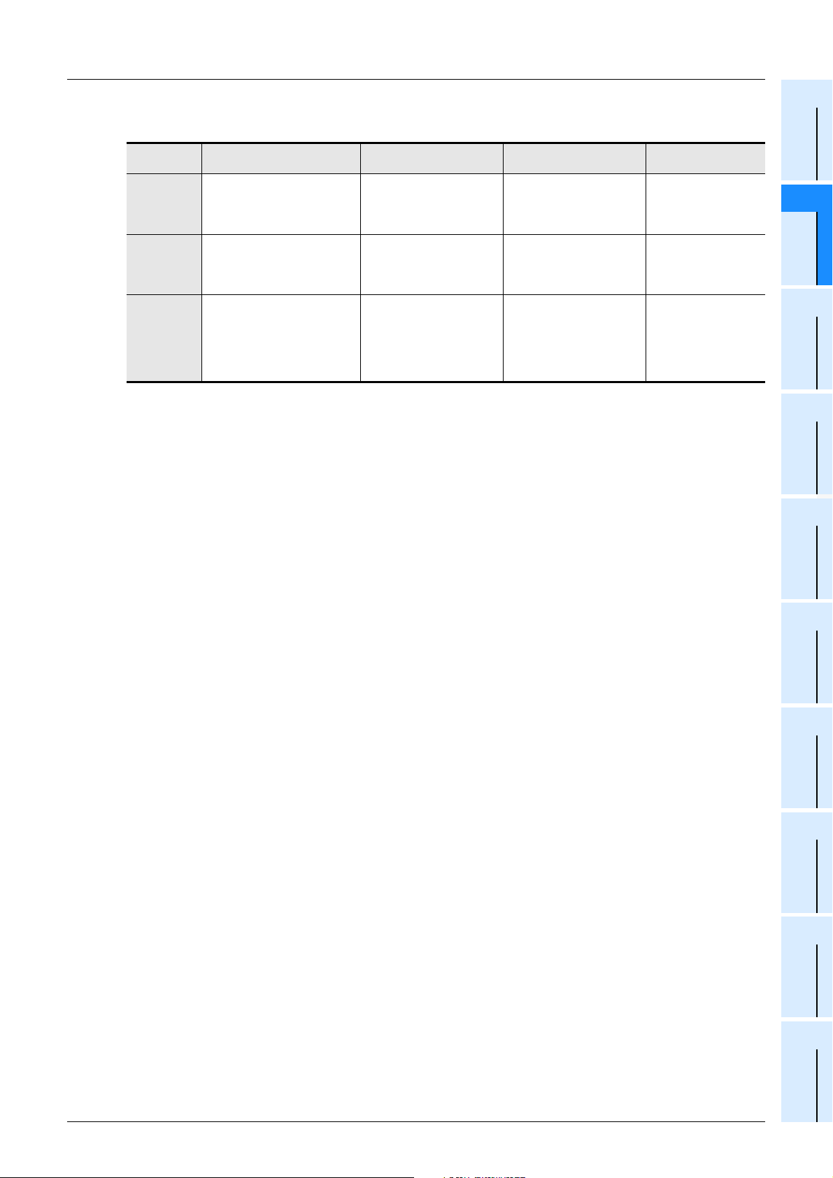
FXCPU Structured Programming Manual
[Device & Common]
3. FX0S/FX0/FX0N/FXU/FX2C PLCs
2 Devices in Detail
2.4 State Relay [S]
1
Device Outline
General type Latched (backed-up) type
S0 to S63
FX0S/FX0
PLC
FX0N PLC - -
FXU/FX2C
PLC
(S0 to S9 are provided for the
(S0 to S9 are provided for the
64 points
initial state.)
S0 to S499
500 points
initial state.)
(S10 to S19 are provided for
zero return.)
*4
*1
S500 to S899
400 points
---
*2
Fixed latched (backed-up)
(S0 to S9 are provided for the
type
S0 to S127
128 points
initial state.)
-
*3
Annunciator type
-
S900 to S999
100 points
*2
*1. This area is not latched (backed up). It can be changed to the latched (backed-up) area by parameter
setting.
*2. This area is latched (backed up). It can be changed to the non-latched (non-backed-up) area by
parameter setting.
*3. This area is fixed to the latched (backed-up) type. (The contents can be cleared by the RST and ZRST
instructions.)
*4. This area is fixed to the non-latched (non-backed-up) type. The characteristics of latch (backup)
cannot be changed.
Constant
2
Devices in
Detail
3
Specified the
Device &
4
Special Device
5
Errors
6
Types and
Setting of
Parameters
7
Other Functions
45
Page 48
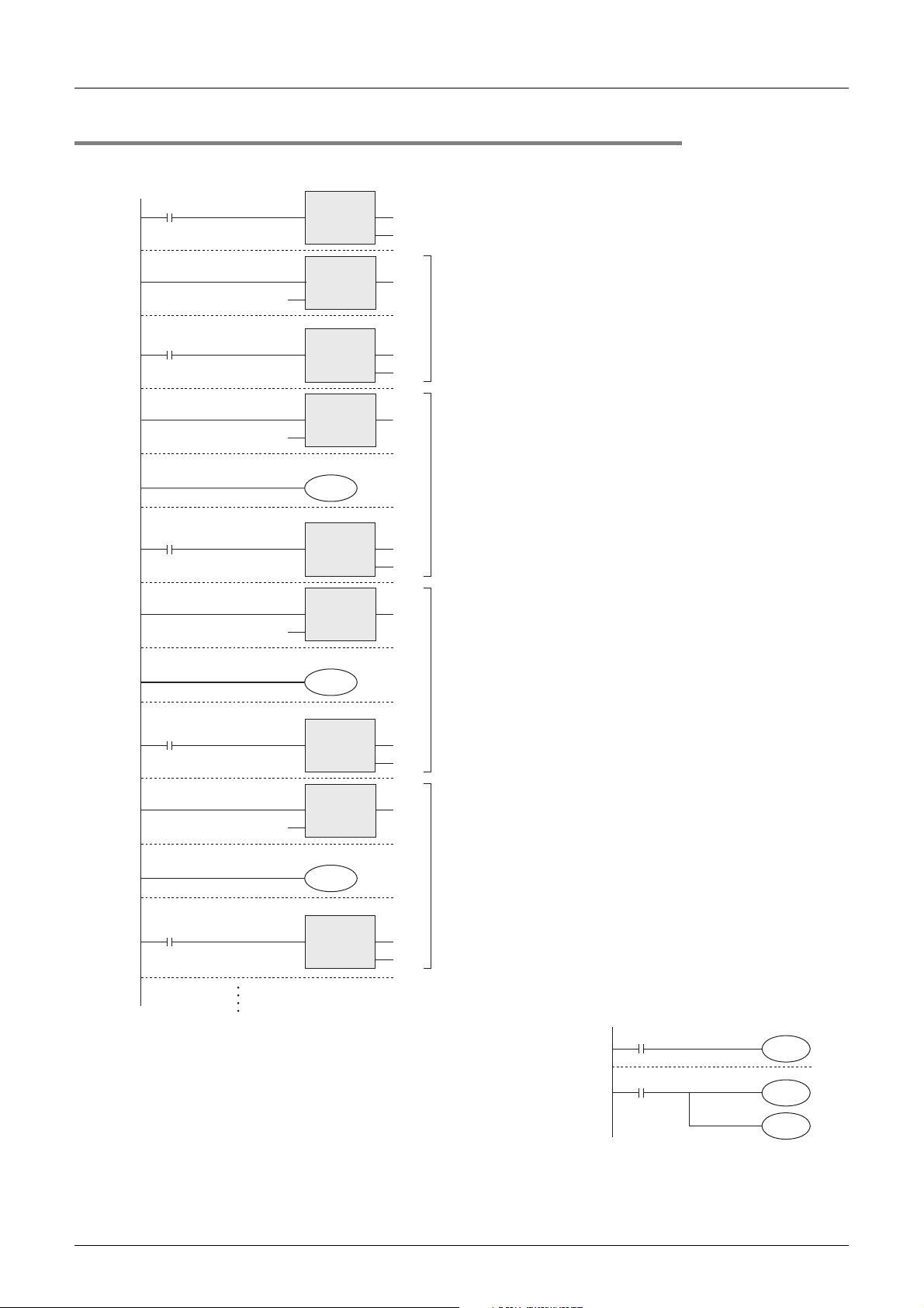
FXCPU Structured Programming Manual
[Device & Common]
2.4.2 Functions and operation examples
1. General type
M8002
S2
Start
X000
S20
Lower limit
X001
SET
EN ENO
STL
EN ENO
s
SET
EN ENO
STL
EN ENO
s
Moving down
Y000
SET
EN ENO
d
S2
d
S20
d
S21
S2 process
S20 process
2 Devices in Detail
2.4 State Relay [S]
In the stepping type process control shown in the
left figure, when the start signal X000 turns ON,
the state relay S20 is set (turned ON) and the
solenoid valve Y000 for moving down is
activated.
When the lower limit switch X001 turns ON, the
state relay S21 is set (turned ON) and the
solenoid valve Y001 for clamping is activated.
When the clamp confirmation limit switch X002
turns ON, the state relay S22 is set (turned ON).
When the operation proceeds to the next step,
the state relay in the preceding step is
automatically reset (turned OFF).
When the PLC is turned OFF, all of general type
state relays are turned OFF.
When the ON/OFF status just before power
interruption is required for restart, use latched
(backed-up) type state relays.
STL
EN ENO
s
S21
Clamping
S21 process
S22
S22 process
Clamping
X002
Upper limit
X003
S22
Y001
SET
EN ENO
d
STL
EN ENO
s
Moving up
Y002
SET
EN ENO
d
State relays have many normally-open contacts and normally-closed
contacts in the same way as auxiliary relays, and these contacts can
be used arbitrarily in sequence programs.
When state relays (S) are not used for step ladder instructions, they
can be used in general sequences in the same way as auxiliary relays
(M) (as shown in the right figure).
X001
S10
S10
M30
Y005
46
Page 49
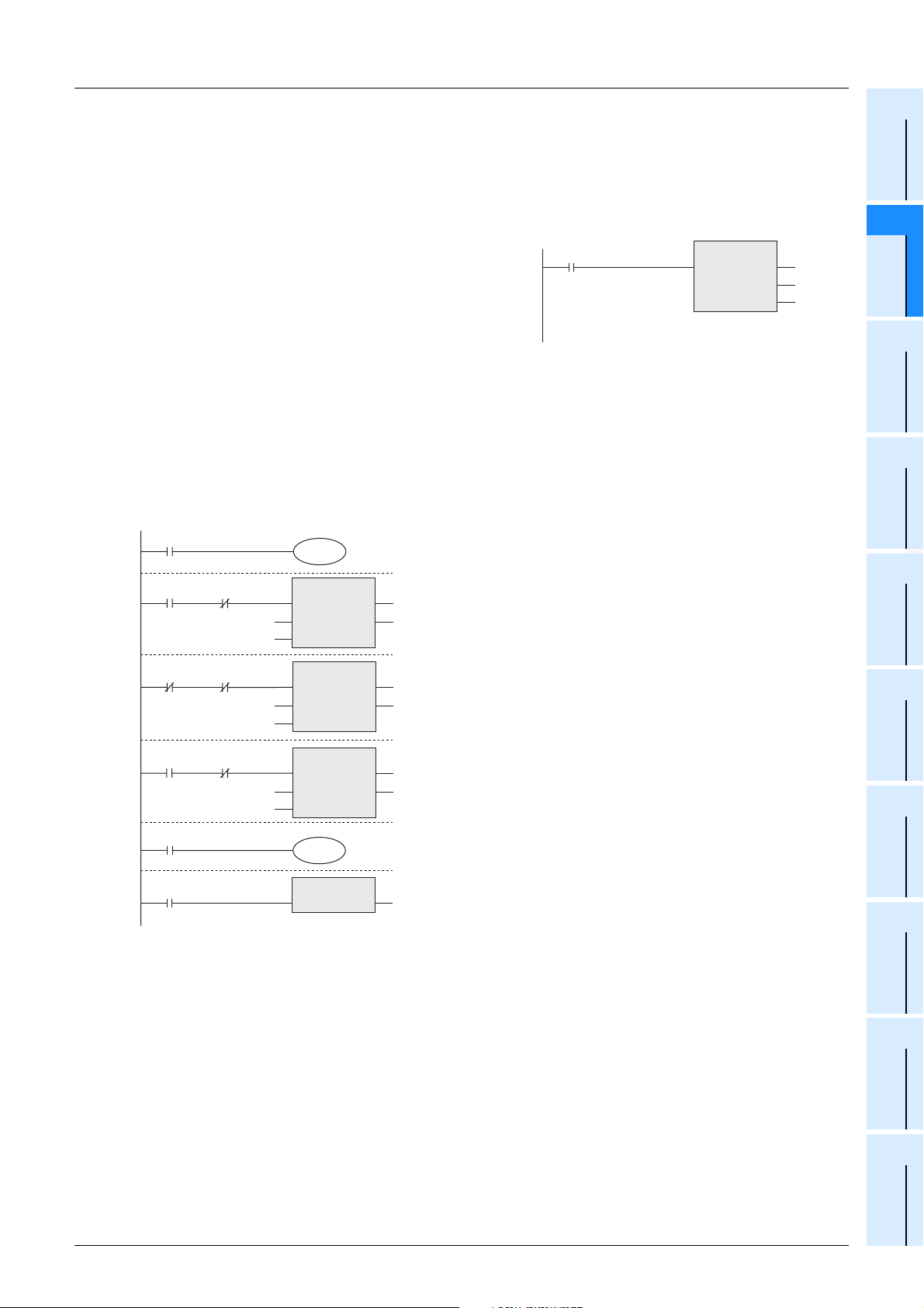
FXCPU Structured Programming Manual
[Device & Common]
2. Latched (backed-up) type
• Latched (backed-up) type state relays store their ON/OFF status even if the power is shut down while the
PLC is operating, so the operation can be restarted after shutdown from the previous last point in the
process.
Latched (backed-up) type state relays are backed up by a battery, EEPROM, etc. built in the PLC.
• When using latched (backed-up) type state relays as
general type state relays, provide a reset circuit shown in
the right figure around the head step in the program.
3. Annunciator type
Annunciator type state relays can be also used as outputs for external fault diagnosis.
For example, when an external fault diagnosis circuit shown in the figure below is created and the contents of
the special data register D8049 are monitored, the smallest number out of the active state relays S900 to
S999 is displayed.
If two or more faults have occurred, the smallest state relay number having a fault is displayed at first. When
the displayed fault is cleared, the next smallest state relay number having a fault is stored in D8049 and
displayed.
M8000
T0
M8049
EN
s
m
ANS
ENO
d
RUN monitor
X000Y000
K10
2 Devices in Detail
2.4 State Relay [S]
→ For details on each backup method, refer to Section 1.2.
ZRST
EN ENO
S1000 to S1200
are initialized.
S900
M8002
Initial pulse
·
When the special auxiliary relay M8049 is driven, monitoring
becomes valid.
·
If the forward end detection input X000 is not activated within
1 second after the forward output Y000 is driven, S900 is
activated.
d1
d2
S1000
S1200
Constant
1
Device Outline
2
Devices in
Detail
3
Specified the
Device &
4
Special Device
5
Errors
X002X001
T1
K20
X004X003
T2
K100
M8048
X005
ANS
EN
s
m
EN
s
m
EN ENO
ENO
ANS
ENO
Y010
ANRP
·
If both the upper limit detection input X001 and the lower limit
d
S901
d
S902
detection input X002 are deactivated at the same time for 2
seconds or more, S901 is activated.
·
In a machine whose takt time is less than 10 seconds,if the
switch X004 which is designed to be activated during one-cycle
operation of the machine is not activated while the continuous
operation mode input X003 is ON, S902 is activated.
·
When any of annunciator type state relays S900 to S999 turns
ON, the special auxiliary relay M8048 is activated and the fault
display output Y010 is activated.
·
The state relays activated by the external fault diagnosis program
can be turned OFF by the reset button X005.
Every time X005 is set to ON, the active annunciator type state
relay having the smallest number is reset in turn.
While the special auxiliary relay M8049 is not driven, annunciator type state relays can be used as latched
(backed-up) type state relays in sequence programs in the same way as general type state relays.
6
Types and
Setting of
Parameters
7
Other Functions
47
Page 50
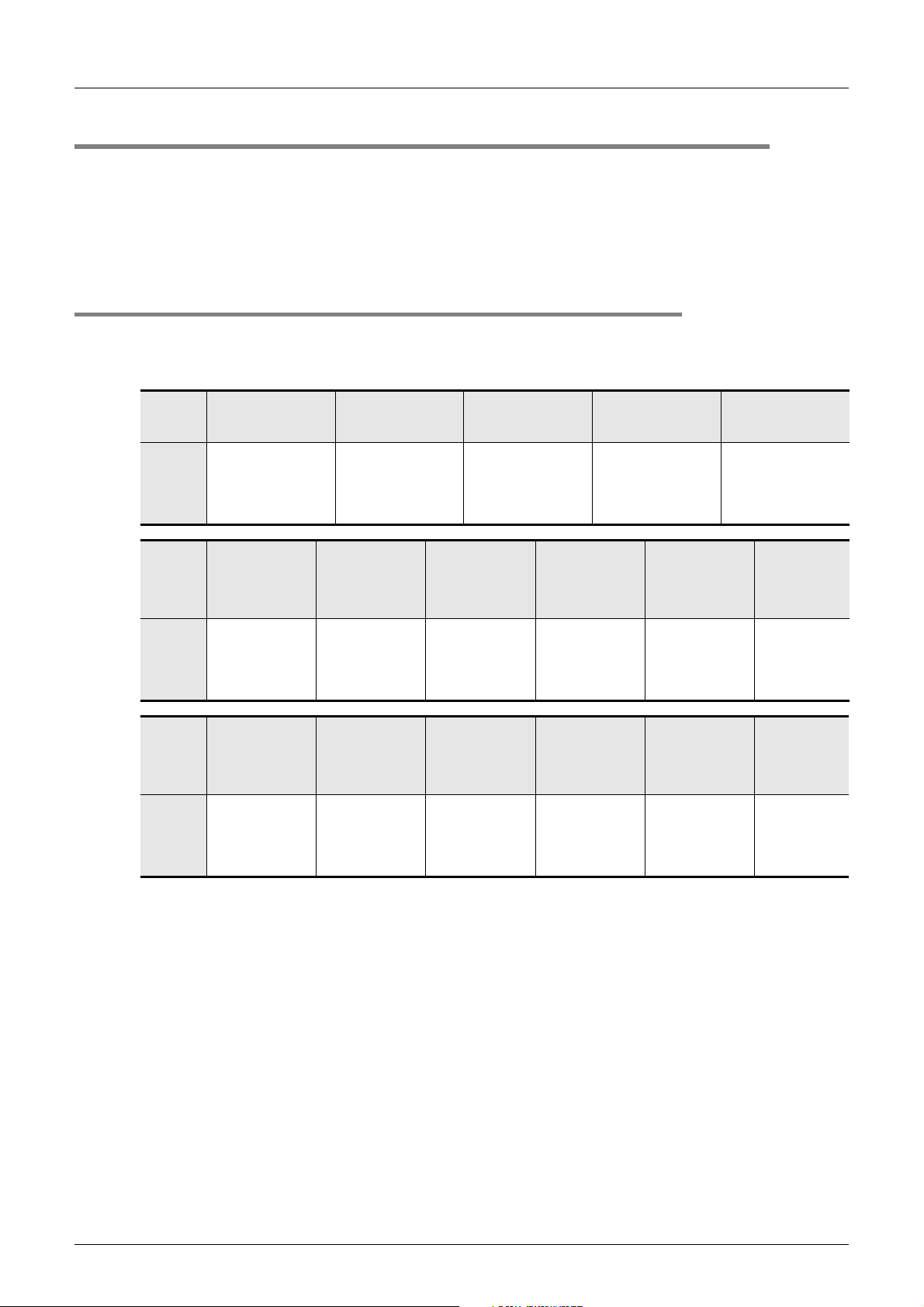
FXCPU Structured Programming Manual
[Device & Common]
2.5 Timer [T]
Timers add and count clock pulses of 1 ms, 10 ms, 100 ms, etc. inside the PLC. When the count value
reaches a specified set value, the output contact of the timer turns ON.
A set value can be directly specified by a constant (K) in the program memory, or indirectly specified by the
contents of a data register (D).
In timers, "TS" indicates a contact, "TC" indicates a coil, and "TN" indicates the current value.
→ Refer to the Q/L/F Structured Programming Manual (Fundamentals).
2.5.1 Numbers of timers
The table below shows timer (T) numbers. (Numbers are assigned in decimal.)
1. FX3S/FX3G/FX3GC/FX3U/FX3UC PLCs
2 Devices in Detail
2.5 Timer [T]
FX3U/
FX3UC
PLC
FX3G/
FX3GC
PLC
FX3S PLC
For 100 ms pulses
0.1 to 3276.7 sec
T0 to T199
200 points
----------------------------
Routine program type
T192 to T199
For 100 ms pulses
0.1 to 3276.7 sec
T0 to T199
200 points
----------------------Routine program
type T192 to T199
For 100 ms pulses
0.1 to 3276.7 sec
T0 to T62
63 points
For 10 ms pulses
0.01 to 327.67 sec
T200 to T245
46 points
For 10 ms pulses
0.01 to 327.67 sec
T200 to T245
46 points
For 100/10 ms
pulses
0.1 to 3276.7 sec
0.01 to 327.67 sec
T32 to T62
31 points
*3
Retentive type for
1 ms pulses
0.001 to 32.767 sec
T246 to T249
4 points
Interrupt execution
latched (backed-up)
type*
Retentive type for
1 ms pulses
0.001 to 32.767
sec
T246 to T249
Interrupt execution
latched (backed-
For 1 ms pulses
0.001 to 32.767
T63 to T127
4 points*
up) type
sec
65 points
2
Retentive type for 100
*1
0.1 to 3276.7 sec
Latched (backed-up)
1
Retentive type for
100 ms pulses
0.1 to 3276.7 sec
T250 to T255
Latched (backed-
Retentive type for
1 ms pulses
0.001 to 32.767
T128 to T131
Interrupt execution
latched (backed-
6 points
up) type
sec
4 points
up) type
*2
*2
ms pulses
T250 to T255
*1
6 points
*1
type
For 1 ms pulses
0.001 to 32.767
T256 to T319
64 points
Retentive type for
100 ms pulses
0.1 to 3276.7 sec
T132 to T137
6 points
Latched (backed-
up) type
0.001 to 32.767 sec
sec
*2
For 1 ms pulses
T256 to T511
256 points
Variable
potentiometer
type
Numeric value
from 0 to 255
2 built-in points
(Only in FX3G
PLC)
Variable
potentiometer
type
Numeric value
from 0 to 255
2 built-in points
*4
48
Timer numbers not used for timers can be used as data registers for storing numeric values.
*1. Retentive type timers are backed up by the battery in FX
*2. Retentive type timers are backed up by the EEPROM memory (built in PLC) in FX
3U/FX3UC PLCs.
3S/FX3G/FX3GC
PLCs.
*3. 100 ms timers are changed to 10 ms timers when the special auxiliary relay M8028 is driven.
*4. This function is not supported in the FX
3S-30M/E-2AD PLC.
Page 51
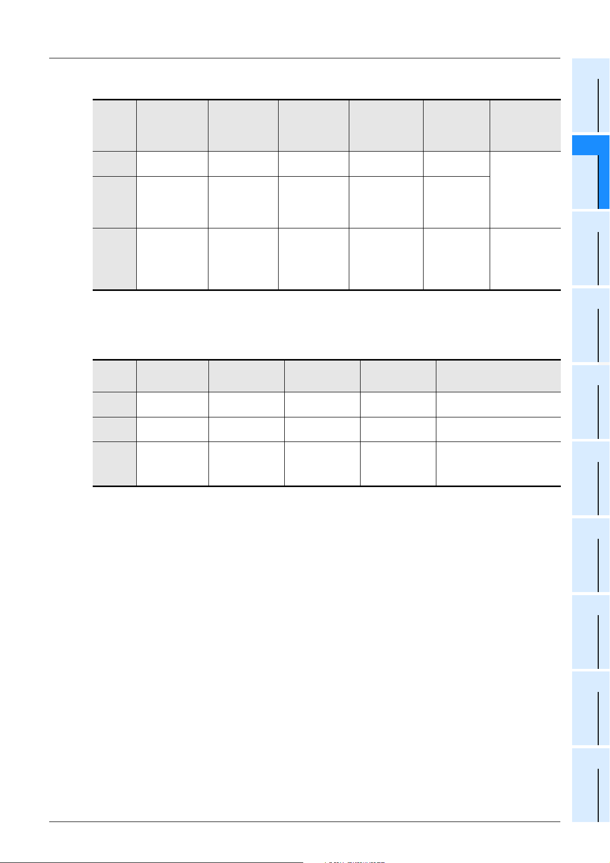
FXCPU Structured Programming Manual
[Device & Common]
2. FX1S/FX1N/FX1NC/FX2N/FX2NC PLCs
2 Devices in Detail
2.5 Timer [T]
1
Device Outline
FX1S PLC
FX1N/
FX1NC
PLC
FX2N/
FX2NC
PLC
For 100 ms pulses
0.1 to 3276.7 sec
T0 to T31
32 points
T0 to T199
200 points
T0 to T199
200 points
----------------------Routine program
type T192 to T199
For 100/10 ms
pulses
0.1 to 3276.7 sec
0.01 to 327.67 sec
T32 to T62
31 points
*1
-
-
For 10 ms pulses
0.01 to 327.67 sec
-
T200 to T245
46 points
T200 to T245
46 points
For 1 ms pulses
0.001 to 32.767 sec
T63
1 point
T246 to T249
4 points
Capacitor latched
(backed-up) type
(Retentive type)
T246 to T249
4 points
Interrupt execution
latched (backed-up)
type
(Retentive type)
Retentive type
for 100 ms
pulses
0.1 to 3276.7 sec
-
T250 to T255
6 points
Capacitor latched
(backed-up) type
T250 to T255
6 points
Capacitor latched
(backed-up) type
Timer numbers not used for timers can be used as data registers for storing numeric values.
*1. 100 ms timers are changed to 10 ms timers when the special auxiliary relay M8028 is driven.
3. FX0S/FX0/FX0N/FXU/FX2C PLCs
Retentive type for
100 ms pulses
0.1 to 3276.7 sec
*2
T250 to T255
6 points
Variable potentiometer type
Numeric value from 0 to 255
*2
8 points for function board
FX0S/FX0
PLC
FX0N PLC
FXU/FX2C
PLC
For 100 ms pulses
0.1 to 3276.7 sec
T0 to T55
56 points
T0 to T62
63 points
Routine program
type T192 to T199
For 10 ms pulses
0.01 to 327.67 sec
(T32 to T55)
(24 points)
(T32 to T62)
(31 points)
T200 to T245
46 points
*1
*1
For 1 ms pulses
0.001 to 32.767 sec
- - 1 built-in point
T63 - 2 built-in points
T246 to T249
4 points
Retentive type
Interrupt execution
Variable
potentiometer
type
Numeric value
from 0 to 255
2 built-in points
8 points for
function board
(Only in FX1S/
FX1N PLCs)
8 points for
function board
(Only in FX2N
PLC)
Constant
Parameters
2
Devices in
Detail
3
Specified the
Device &
4
Special Device
5
Errors
6
Types and
Setting of
Timer numbers not used for timers can be used as data registers for storing numeric values.
*1. 100 ms timers are changed to 10 ms timers when the special auxiliary relay M8028 is driven.
In FX
0 PLCs, this function is available in Ver. 1.01 and later.
*2. They are backed up against power interruption.
7
Other Functions
49
Page 52
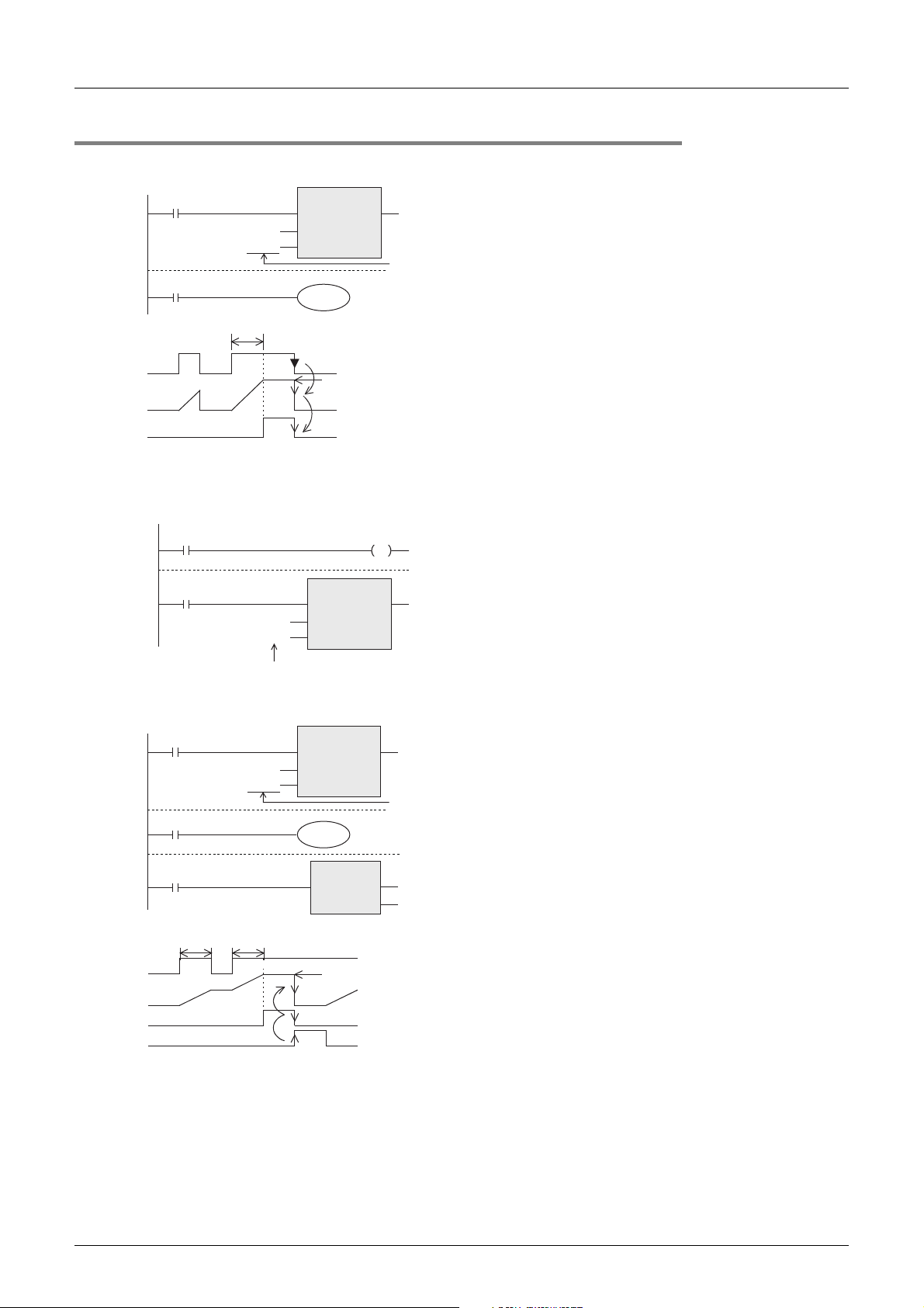
FXCPU Structured Programming Manual
[Device & Common]
2.5.2 Functions and operation examples
1. General type
X000
TC200
K123
TS200
1.23 sec
X000
Current
value
Y000
OUT_T
EN ENO
TCoil
TValue
Y000
Set value
Set value (constant)
A data register can
be specified instead.
2 Devices in Detail
2.5 Timer [T]
When the drive input X000 of the timer T200
turns ON, the current value counter for T200
adds and counts clock pulses of 10 ms. When
the count value becomes equivalent to the set
value K123, the output contact of the timer turns
ON.
In other words, the output contact turns ON 1.23
seconds after the coil is driven.
When the drive input X000 turns OFF or when
the power is turned OFF, the timer is reset and
the output contact turns OFF.
• The program of 100 ms/10 ms type timer of the FX
0S, FX0, FX0N, FX1S and FX3S PLCs.
100 ms timers are changed to timers which operate based on the 10 ms base clock when the special
auxiliary relay M8028 is driven in the program.
M8000 M8028
RUN monitor
X003
TC32
K100
1-second timer
OUT_T
EN ENO
TCoil
TValue
2. Retentive type
X000
TS250
X002
X001
Current
value
Y001
X002
t1
Retentive
time
EN ENO
TC250
K345
t2
Retentive time
TCoil
TValue
t1 + t2 = 34.5 sec
OUT_T
Y001
RST
EN ENO
Set value
Set value (constant)
A data register can
be specified instead.
d
TC250
When the drive input X001 of the timer T250
turns ON, the current value counter for T250
adds and counts clock pulses of 100 ms. When
the count value becomes equivalent to the set
value K345, the output contact of the timer turns
ON.
Even if the drive input X001 turns OFF or if the
power is turned OFF during counting, the timer
continues counting when the operation restarts.
The retentive operating time is 34.5 seconds.
When the reset input X002 turns ON, the timer is
reset and the output contact turns OFF.
50
Page 53
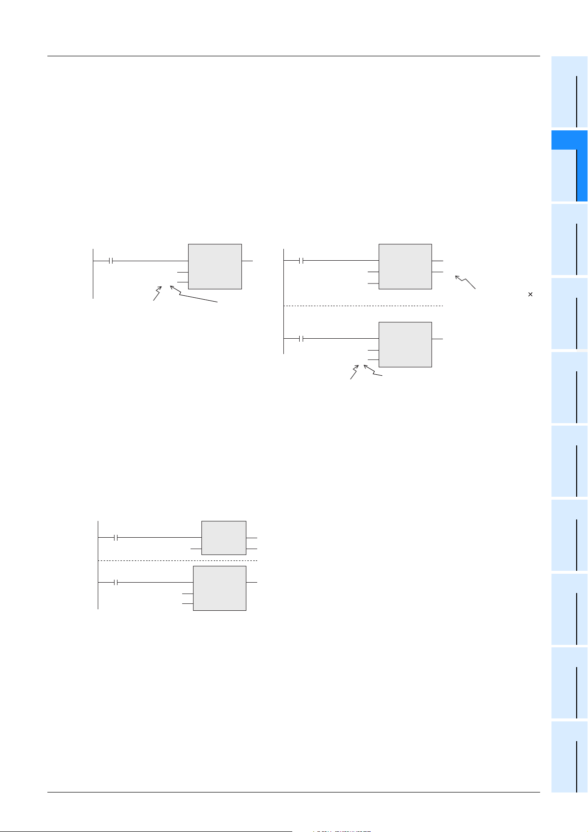
FXCPU Structured Programming Manual
[Device & Common]
3. Variable potentiometer type
• Program for built-in analog variable potentiometers
Program values for built-in analog variable potentiometers are stored in the following special data registers
as numeric data within the range from 0 to 255 in accordance with the scale position.
Values received as numeric values can be specified as the indirectly specified value for a timer to provide
variable potentiometer type analog timers.
[Special data registers]
2 Devices in Detail
2.5 Timer [T]
1
Device Outline
2
Devices in
Detail
•FX1S, FX1N, FX3S*1, FX3G PLC
VR1→D8030
VR2→D8031
[Example of basic circuit] [Example of applied circuit]
X003
TC10
D8030
Data register which stores
an analog variable potentiometer
value (integer in range from 0 to 255)
*1. FX
3S-30M/E-2AD are not applicable to built-in analog variable potentiometers.
OUT_T
EN ENO
TCoil
TValue
•FX0S, FX0 PLC
D8013
(0 to 25.5 sec)
M8000
RUN monitor
X003
The set value range can be changed
(to "32,767" maximum) by multiplying the contents of the
data register by "n".
Do not use D1 in other programs.
D8031
TC10
K2
D0
•FX0N PLC
VR1→D8013(D8030)
VR2→D8031
MUL_E
EN
_IN
_IN
EN ENO
TCoil
TValue
(0 to 51 sec)
ENO
OUT_T
D0
[Value of D8031 (VR2)] 2
Transferred to (D1, D0)
• Program for analog variable potentiometers on function board
Values of analog variable potentiometers which can be built in the PLC as a function board can be
received as numeric data in the range from 0 to 255 in accordance with the scale position.
Values received as numeric values can be specified as timer function values to provide variable
potentiometer type analog timers.
Use the VRRD function to put analog variable potentiometer values into the PLC.
X000
VRRD
ENsENO
d
The analog value of the variable potentiometer No. 0 is
converted into 8-bit binary value, and the value in the range
from 0 to 255 is transferred to D0.
D0K0
In this example, D0 is used as the timer set value.
X001
TC0
D0
OUT_T
EN ENO
TCoil
TValue
3
Specified the
Device &
Constant
4
Special Device
5
Errors
6
Types and
Setting of
Parameters
7
Other Functions
Use the VRSC instruction to put the value of an analog variable potentiometer as a numeric value in the
range from 0 to 10 in accordance with the scale position.
51
Page 54
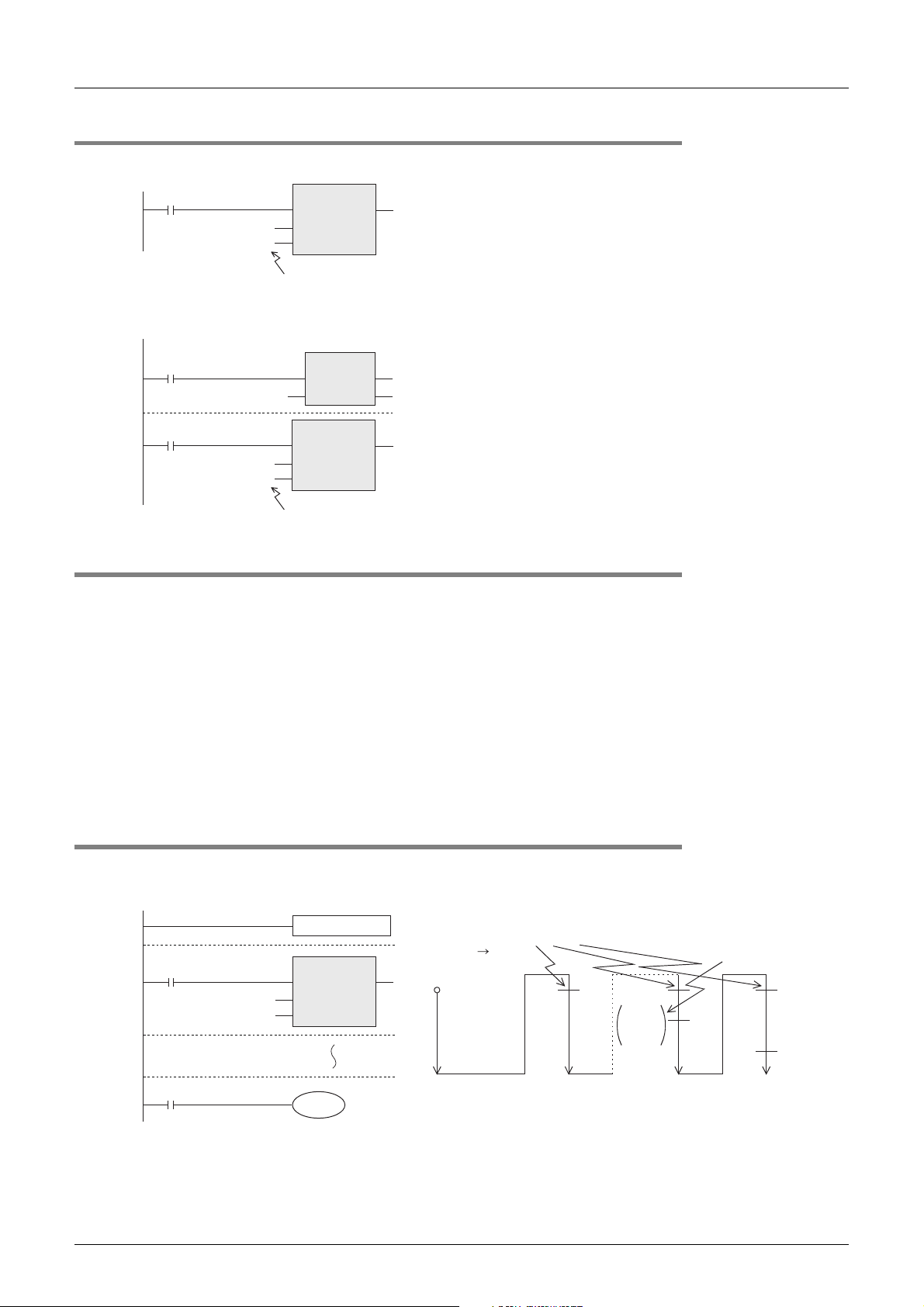
FXCPU Structured Programming Manual
[Device & Common]
2.5.3 Set value specification method
1. Specification using a constant (K)
X003
TC10
K100
2. Indirect specification using a data register
X001
K100
X003
TC10
D5
OUT_T
EN ENO
TCoil
TValue
Constant (decimal integer)
10-sec timer
MOV
ENsENO
d
OUT_T
EN ENO
TCoil
TValue
D5
2 Devices in Detail
2.5 Timer [T]
T10 is a timer for 100 ms (0.1 s) pulses.
When the constant "100" is specified, T10 works as a
10-second timer (0.1 sec × 100 = 10 sec).
Write in advance a value to the data register used for
indirect specification in a program, or set such a value in
advance using a digital switch.
Note that the set value of a latched (backed-up) type
register can be indefinite when the battery voltage
becomes low.
D5=K100
10-sec timer
2.5.4 Cautions on use
1) Use timers T192 to T199 in subroutines and interrupt routines. These timers execute counting when a coil
instruction or END instruction is executed.
Once the count value of such a timer has reached the set value, the timer output contact turns ON when
a coil instruction or END instruction is executed.
Because general type timers execute counting only when a coil instruction is executed (refer to "2.5.5
Details of timer operations and timer accuracy" below), they do not operate normally if they are used in
subroutines or interrupt routines in which a coil instruction is executed only in a certain condition.
2) If a retentive type timer for 1 ms pulses is used in a subroutine or interrupt routine, its output contact turns
ON when the first coil instruction is executed after its count value has reached the set value.
3) For writing the symbolic information and changing the set values of timers and counters using a
peripheral equipment, it is recommended to create programs with the set values specified indirectly.
If the set values are specified directly, programs cannot be restored from the symbolic information after
the set values are changed.
2.5.5 Details of timer operations and timer accuracy
A timer (except interrupt execution type) starts counting when the coil is driven, and its output contact turns
ON when the first coil instruction is executed after the timer has reached timeout.
Counting operation (If the operation cycle is long,
it automatically counts two or more clocks.)
X010
TS0
TC0
K12
Input processing
OUT_T
EN ENO
TCoil
TValue
Y010
X010=OFF ON
Timer starts counting.
1st cycle
Contact is not
activated at this point.
T 0
1.2
sec
timeout
2nd cycle "n"th cycle "n+1"th cycle
Contact is
activated.
Y010
ON
52
Page 55
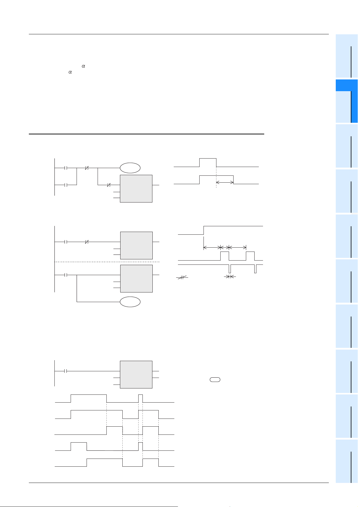
FXCPU Structured Programming Manual
[Device & Common]
As shown in the above operation diagram, the accuracy of operation of the timer contact after the coil is
driven until the contact turns ON is shown in the following outline expression:
:0.001 sec (timer for 1 ms), 0.01 sec (timer for 10 ms) or 0.1 sec (timer for 100 ms)
+T
0
-
T
If the contact is programmed before the timer coil, "+2T0" results in the worst case.
When the timer set value is "0", the output contact turns ON when a coil instruction is executed in the next
cycle.
An interrupt execution type timer for 1 ms pulses counts clock pulses of 1 ms as an interrupt processing after
a coil instruction has been executed.
T :Timer set value (sec)
:Operation cycle (sec)
T
0
2 Devices in Detail
2.5 Timer [T]
1
Device Outline
2
Devices in
Detail
2.5.6 Program examples [Off-delay timer and flicker timer]
Off-delay timer
X001
TS5
X001Y000
TC5
K200
Y000
OUT_T
EN ENO
TCoil
TValue
X001
Y000
Flicker timer
X001 TS2
TC1
K20
TS1
TC2
K10
OUT_T
EN ENO
TCoil
TValue
OUT_T
EN ENO
TCoil
TValue
Y000
In addition, the flicker operation can be performed by the ALT instruction.
X001
2 sec 1 sec
T1 T2 T1
Y000
T 2
( )
T5 (20 sec)
2 sec
One operation cycle
3
Specified the
Device &
Constant
4
Special Device
5
Errors
6
Types and
Setting of
Parameters
7
Other Functions
Multi-timer using the STMR instruction
Off-delay timers, one-shot timers and flicker timers can be easily created using this instruction.
Off-delay timer and one-shot timer
EN
s
m
STMR
ENO
10 sec10 sec
•
The value specified in "m" is handled as
d
the set value of a timer specified in input
variable .
The set value is "10 sec." in this example.
•
M0 is an off-delay timer.
•
M1 is a one-shot timer which operates after
the input turns OFF from ON.
•
M2 and M3 are flicker timers, and connected
as shown in the program example below for flicker.
s
X000
M 0
M 1
M 2
M 3
X000
T10 M0
K100
10 sec 10 sec
10 sec
53
Page 56
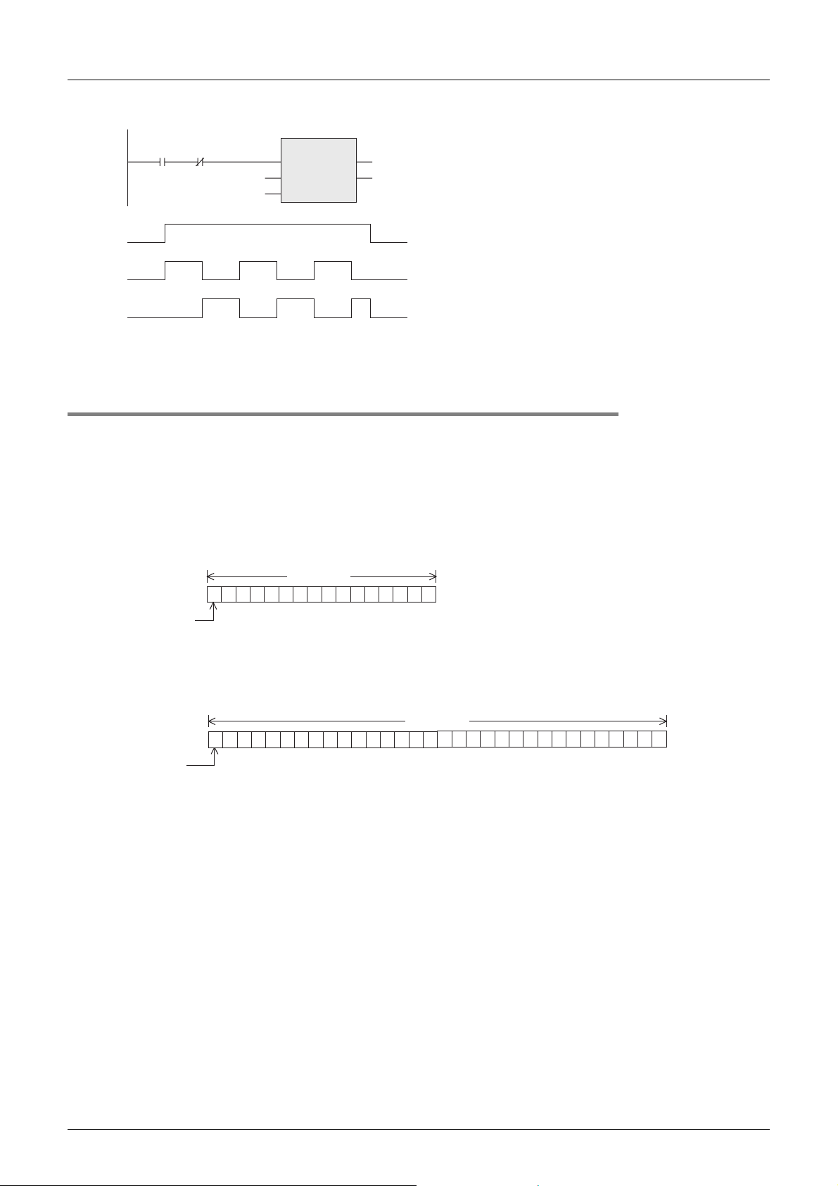
FXCPU Structured Programming Manual
r
[Device & Common]
Flicker timer
2 Devices in Detail
2.5 Timer [T]
X000 M3
T10 M0
K100
X000
M 2
M 1
EN
s
m
STMR
ENO
d
In addition, the timer time can be set according to the switch input time using the teaching timer instruction
TTMR.
2.5.7 Handling timers as numeric devices
In timers, the output contact operating in accordance with the set value is used in some cases, and the
current value is used as numeric data for control in other cases.
The figures below show the structure of timer current value registers. When a timer number is specified in an
input variable of an instruction, the timer is handled as a device which stores 16-bit or 32-bit data in the same
way as data registers.
1. Structure of timer current value registers
1) 16-bit
•
When M3 is connected as shown in the
left figure, M2 and M1 become flicker outputs.
•
When X000 is set to OFF, M0, M1 and M3 turn
OFF and T10 is reset after the set time.
•
Do not use the timers used here in other
general circuits again.
2,048
4,096
16 bit
512
1,024
256
128
64
32
16
1010101010101010
b0
1
2
4
8
Available numeric value range
16-bit:0 to 32,767
32-bit:-2,147,483,648 to +2,147,483,647
High order Low order
b15
*1
Sign
0 : Positive
1 : Negative
*1.The sign is valid only when a timer is handled as a substitute for a data register.
8,192
16,384
2) 32-bit
262,144
524,288
32 bit
1010101010101010
32,768
65,536
131,072
8,192
16,384
2,048
4,096
512
1,024
256
128
64
32
16
0000111100001111
1
2
4
8
High order Low orde
b31 b0
Sign
0 : Positive
1 : Negative
67,108,864
134,217,728
268,435,456
536,870,912
1,073,741,824
8,388,608
16,777,216
33,554,432
1,048,576
2,097,152
4,194,304
2. Use examples
For the full use of timers as numeric devices, refer to the instruction explanation manual offered separately.
→ FX Structured Programming Manual [Basic & Applied Instruction]
54
Page 57
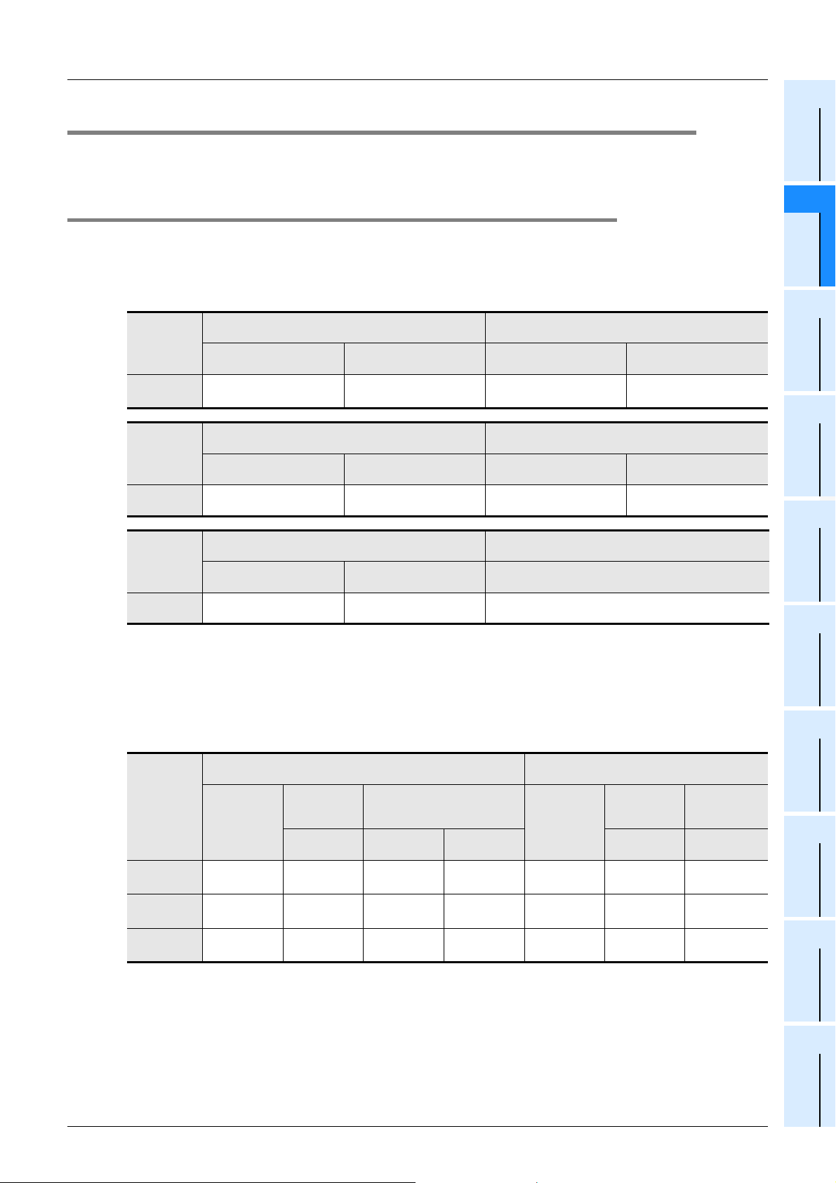
FXCPU Structured Programming Manual
[Device & Common]
2.6 Counter [C]
In counters, "CS" indicates a contact, "CC" indicates a coil, and "CN" indicates the current value.
→ Refer to the Q/L/F Structured Programming Manual (Fundamentals).
2 Devices in Detail
2.6 Counter [C]
1
Device Outline
2.6.1 Numbers of counters
The tables below show counter (C) numbers. (Numbers are assigned in decimal.)
1. In FX3S/FX3G/FX3GC/FX3U/FX3UC PLCs
Counting range: 0 to 32767
General type
FX3U/FX3UC
PLC
FX3G/FX3GC
PLC
FX3S PLC
*1. This area is not latched (backed up). It can be changed to the latched (backed-up) area by parameter
setting.
*2. This area is latched (backed up). It can be changed to the non-latched (non-backed-up) area by
parameter setting.
C0 to C99
100 points
General type
C0 to C15
General type
C0 to C15
*1
Counting range: 0 to 32767
16 points
Counting range: 0 to 32767
16 points
16-bit up-counter
Latched (battery backed-
16-bit up-counter
Fixed latched (EEPROM
16-bit up-counter
Fixed latched (EEPROM
up) type
C100 to C199
100 points
keep) type
C16 to C199
184 points
keep) type
C16 to C31
*2
16 points
→ For high speed counters, refer to Section 2.7.
32-bit bi-directional counter
-2,147,483,648 to +2,147,483,647
General type
C200 to C219
General type
C200 to C219
*1
20 points
32-bit bi-directional counter
-2,147,483,648 to +2,147,483,647
20 points
32-bit bi-directional counter
-2,147,483,648 to +2,147,483,64732
Latched (battery backed-
C220 to C234
Fixed latched (EEPROM
C220 to C234
General type
C200 to C234
35 points
up) type
15 points
keep) type
15 points
*2
Constant
Parameters
2
Devices in
Detail
3
Specified the
Device &
4
Special Device
5
Errors
6
Types and
Setting of
2. In FX1S/FX1N/FX1NC/FX2N/FX2NC PLCs
16-bit up-counter
Counting range: 0 to 32767
FX1S
PLC
FX1N/FX1NC
PLC
FX2N/FX2NC
PLC
General type
C0 to 15
16 points
16 points
100 points
*3
C0 to C15
*3
C0 to C99
*1
Latched
(backed-up)
type
Battery
backed-up
-
-
C100 to C199
100 points
Fixed latched (backed-up) type
*2
EEPROM
backed-up
C16 to C31
16 points
C16 to C31
16 points
--
*3
*3
Capacitor
backed-up
C32 to C199
168 points
General type
--- -
C200 to C219
*3
C200 to C219
*1. This area is not latched (backed up). It can be changed to the latched (backed-up) area by parameter
setting.
*2. This area is latched (backed up). It can be changed to the non-latched (non-backed-up) area by
parameter setting.
*3. The characteristics of latch (backup) cannot be changed using parameters.
Counter numbers not used as counters can be used as data registers to store numeric values.
32-bit bi-directional counter
-2,147,483,648 to +2,147,483,647
Latched
(backed-up)
type
Battery
backed-up
20 points
20 points
*3
*1
-
C220 to C234
15 points
Fixed latched
(backed-up)
C220 to C234
*2
type
Capacitor
backed-up
15 points
-
7
Other Functions
*3
55
Page 58
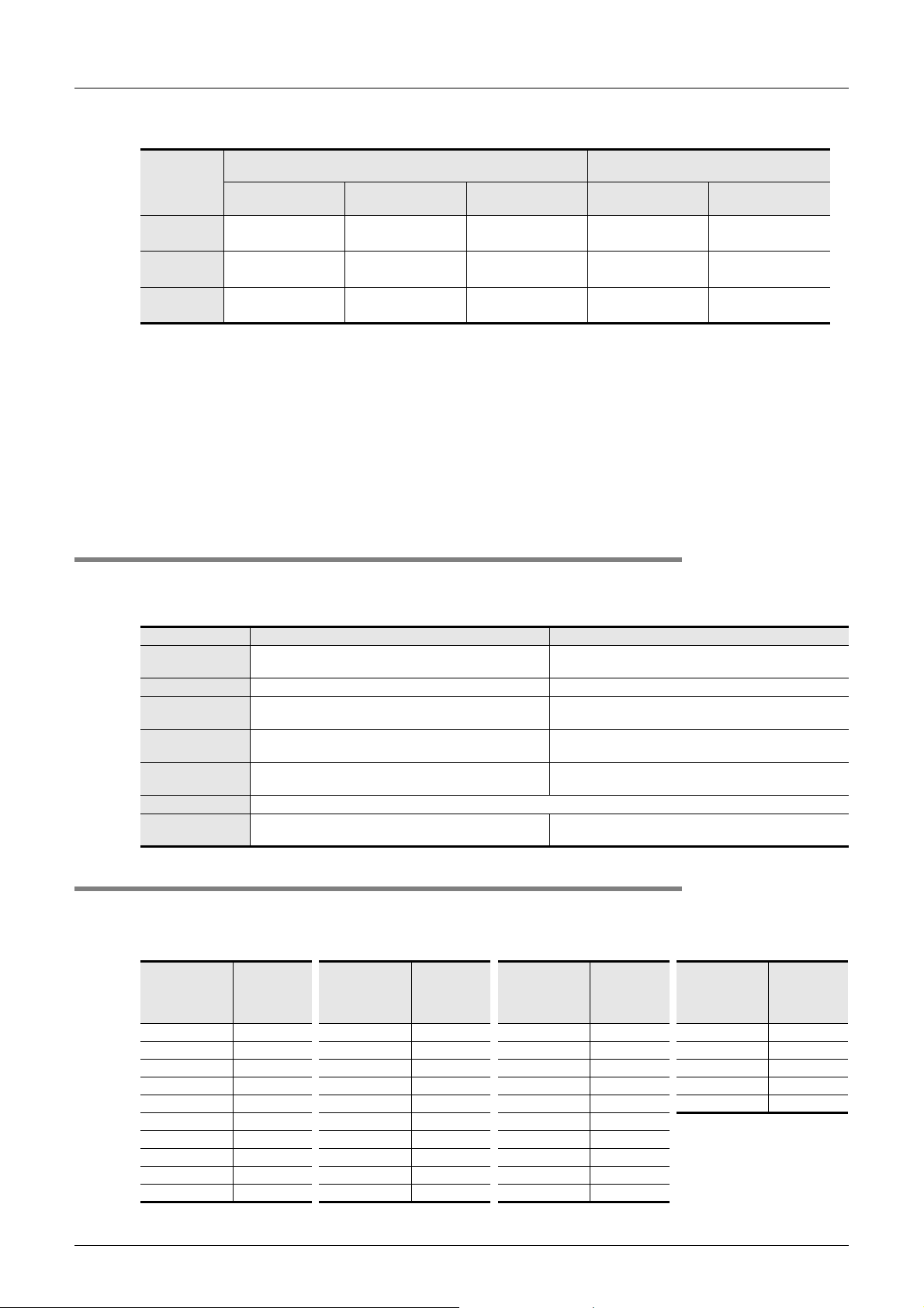
FXCPU Structured Programming Manual
[Device & Common]
3. In FX0S/FX0/FX0N/FXU/FX2C PLCs
2 Devices in Detail
2.6 Counter [C]
General type
FX0S/FX0
PLC
FX0N
PLC
FXU/FX2C
PLC
C0 to 13
14 points
C0 to C15
16 points
C0 to C99
100 points
*4
*4
*1. This area is not latched (backed up). It can be changed to the latched (backed-up) area by parameter
setting.
*2. This area is latched (backed up). It can be changed to the non-latched (non-backed-up) area by
parameter setting.
*3. This area is fixed to the latched (backed-up) type. (The contents can be cleared by the RST and ZRST
instructions.)
*4. This area is fixed to the non-latched (non-backed-up) type. The characteristics of latch (backup)
cannot be changed.
Counter numbers not used as counters can be used as data registers to store numeric values.
2.6.2 Features of counters
The table below shows the features of 16-bit counters and 32-bit counters.
These counters can be used in accordance with the operating condition such as counting direction switching
and counting range.
Item 16-bit counter 32-bit counter
Counting direction Up-counting
Set value 1 to 32767 -2,147,483,648 to +2,147,483,647
Set value
specification
Current value
change
Output contact Latches the operation status after counting up.
Reset operation When the RST instruction is executed, the current value of counter is reset to "0" and the output contact turns OFF.
Current value
register
Constant (K) or data register Constant (K) or a pair of data registers
Does not change after counting up. Changes even after counting up (ring counter).
16-bit 32-bit
16-bit up-counter
Counting range: 0 to 32767
Latched (backed-up)
type
-
-
*1
C100 to C199
100 points
32-bit bi-directional counter
-2,147,483,648 to +2,147,483,647
Fixed latched
(backed-up) type
C14 to C15
*3
2 points
C16 to C31
16 points
*2
*3
-
Up-counting and down-counting can be switched (refer
to Subsection 2.6.3).
Latches the operation status (in up-counting), or is reset
(in down-counting).
General type
--
--
C200 to C219
20 points
Latched (backed-up)
*1
type
C220 to C234
15 points
*2
2.6.3 Related devices (to specify counting direction) [32-bit counter]
FX0S/FX0/FX0N PLCs do not support 32-bit counters.
When an auxiliary relay for switching the counting direction is set to ON, the counter executes down-counting.
When the auxiliary relay is set to OFF, the counter executes up-counting.
56
Counting
Counter No.
C200 M8200 C210 M8210 C220 M8220 C230 M8230
C201 M8201 C211 M8211 C221 M8221 C231 M8231
C202 M8202 C212 M8212 C222 M8222 C232 M8232
C203 M8203 C213 M8213 C223 M8223 C233 M8233
C204 M8204 C214 M8214 C224 M8224 C234 M8234
C205 M8205 C215 M8215 C225 M8225
C206 M8206 C216 M8216 C226 M8226
C207 M8207 C217 M8217 C227 M8227
C208 M8208 C218 M8218 C228 M8228
C209 M8209 C219 M8219 C229 M8229
direction
switching
relay
Counter No.
Counting
direction
switching
relay
Counter No.
Counting
direction
switching
relay
Counter No.
Counting
direction
switching
relay
Page 59
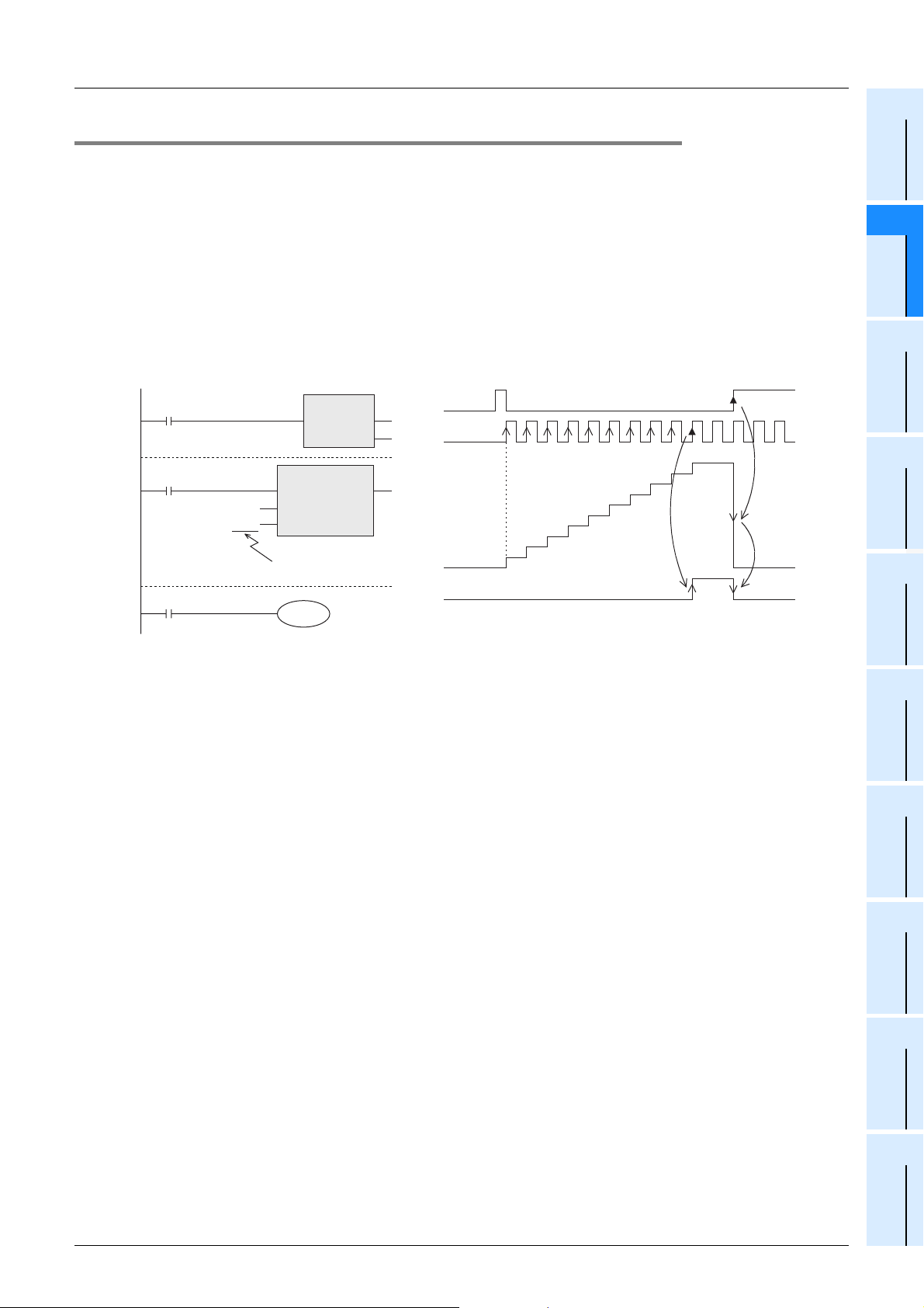
FXCPU Structured Programming Manual
[Device & Common]
2.6.4 Functions and operation examples
1. General type and latched (backed-up) type 16-bit counters
• The valid setting rage of 16-bit binary up-counter is from K1 to K32767 (decimal constant).
K0 causes the same operation as K1, and the output contact turns ON at the first counting.
• In general type counters, the count value is cleared when the PLC is turned OFF.
In latched (backed-up) type counters, the count value just before power interruption is stored. The count
value in the subsequent operation can be added to the previous last count value.
• Every time the coil C0 is driven by the counting input X011, the current value of the counter increases.
When a coil instruction is executed 10 times, the output contact turns ON. After that, the current value of
the counter does not change even if the counting input X011 turns ON.
When the reset input X010 turns ON and then the RST instruction is executed, the current value of the
counter is reset to "0" and the output contact turns OFF.
2 Devices in Detail
2.6 Counter [C]
Constant
1
Device Outline
2
Devices in
Detail
3
Specified the
Device &
X010
X011
CS0
EN ENO
OUT_C
EN ENO
CC0
CCoil
K10
CValue
Set value (constant)
The set value can be
indirectly specified instead.
Y000
RST
d
C0
X010
X011
Current
value
Y000
10
9
8
7
6
5
4
3
2
1
0
• The counter set value can be set directly by a constant (K) as shown above, or specified indirectly by a
data register number.
For example, when D10 is specified and the contents of D10 are "123", it is equivalent to "K123".
• If data beyond the set value is written to the current value register by the MOV instruction, etc., the OUT
coil turns ON and the current value register becomes the set value when the next counting input is
received.
• In a latched (backed-up) type counter, the current value, output contact operation status and reset status of
the counter are latched (backed up) by a battery, EEPROM, etc. built in the PLC.
→ For details on backup methods against power interruption, refer to Section 2.6.
2. General type and latched (backed-up) type 32-bit bidirectional counters
The valid setting range of 32-bit binary bidirectional counters is from -2,147,483,648 to +2,147,483,647
(decimal constant).
The counting direction (up or down) is specified by special auxiliary relays M8200 to M8234.
• When M8UUU is driven for the counter CUUU, the counter executes down-counting.
When M8UUU is not driven for the counter CUUU, the counter executes up-counting. (Refer to the
previous page.)
• The (positive or negative) set value can be specified by a constant (K) or the contents of data registers (D).
When data registers are used, 32-bit data composed of a pair of serial data registers is handled as the set
value.
However, when handling 32-bit data in structured programs, it is not allowed to specify 16-bit data registers
directly, different from simple projects. (Because 32-bit counters have 32-bit length, it is allowed to specify
32-bit data directly.) Use a label when handling 32-bit data.
For example, when specifying 32-bit data using two data registers D1 and D0, define D0 using a global
label.
4
Special Device
5
Errors
6
Types and
Setting of
Parameters
7
Other Functions
57
Page 60
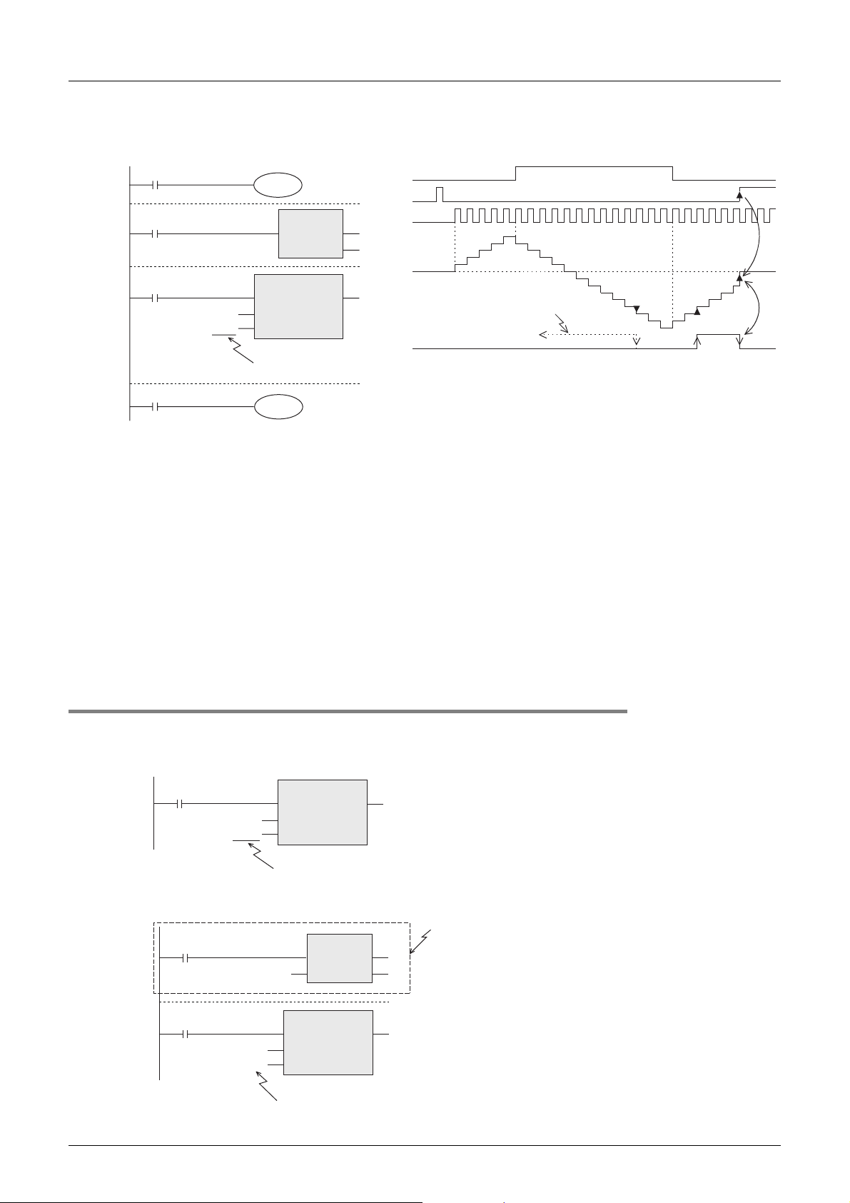
FXCPU Structured Programming Manual
[Device & Common]
• When the coil C200 is driven by the counting input X014, the counter starts up-counting or down-counting.
When the current value of the counter increases from "-6" to "-5", the output contact turns ON. When the
current value decreases from "-5" to "-6", the output contact turns OFF.
X012
M8200
X013
X014
CC200
CS200
EN ENO
CCoil
K-5
CValue
Set value (constant)
The set value can be
indirectly specified instead.
• The current value increases or decreases without regard to the operation of the output contact.
When the counter executes up-counting from "2,147,483,647", the count value becomes "-2,147,483,648".
In the same way, when the counter executes down-counting from "-2,147,483,648", the count value
becomes "2,147,483,647". (This type of counter is called ring counter.)
• When the reset input X013 turns ON and then the RST instruction is executed, the current value of the
counter is reset to "0" and the output contact turns OFF.
• In a latched type counter, the current value, output contact operation status and reset status of the counter
are latched (backed up) by a battery, etc. in the PLC.
→ For details on backup methods against power interruption, refer to Section 1.2.
• A 32-bit counter can be used as a 32-bit data register. 32-bit counters cannot be handled as target devices
in 16-bit applied instructions.
• If data beyond the set value is written to the current value register by the DMOV instruction, etc., the
counter continues counting and the contact does not change when the next counting input is received.
RST
EN ENO
d
OUT_C_32
Y001
C200
Up-counting
X012
X013
X014
Current
value
0
When output contact has
been already turned ON.
Y001
454
3
2
1
Down-counting
3
2
1
0
2 Devices in Detail
2.6 Counter [C]
Up-counting
0
-1
-2
-3
-4
-5
-6
-7
-7
-8
-3
-4
-5
-6
2.6.5 Set value specification method
1. 16-bit counter
1) Direct specification using a constant (K)
X003
CC0
K100
2) Indirect specification using a data register (D)
X001
X003
CC0
D5
OUT_C
EN ENO
CCoil
CValue
Constant (decimal constant)1 to 32,767
100 counts
MOV
ENsENO
K100
OUT_C
EN ENO
CCoil
CValue
D5:100
100 counts
Write in advance a value to the data register used
for indirect specification in a program, or set such
a value in advance using a digital switch.
d
D5
Note that the set value of a latched (backed-up) type
register can be indefinite when the battery voltage
becomes low.
58
Page 61
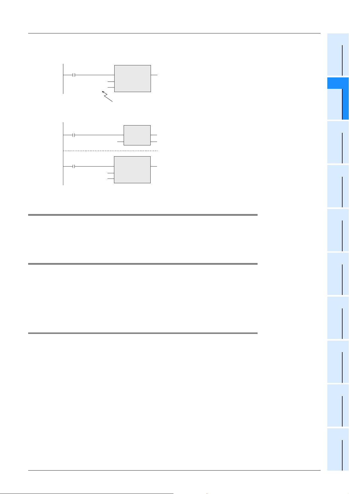
FXCPU Structured Programming Manual
[Device & Common]
2. 32-bit counter
1) Direct specification using a constant (K)
2 Devices in Detail
2.6 Counter [C]
1
Device Outline
X003
CC200
K43210
2) Indirect specification using a data register (D)
X001
K43210
X003
CC200
D5
*1 Make sure data registers used for indirect specification are not used in other programs.
2.6.6 Cautions on use
For writing the symbolic information and changing the set values of timers and counters using a peripheral
equipment, it is recommended to create programs with the set values specified indirectly.
If the set values are specified directly, programs cannot be restored from the symbolic information after the
set values are changed.
OUT_C_32
EN ENO
CCoil
CValue
Constant (decimal constant)-2,147,483,648 to +2,147,483,647
43210 counts
DMOV
OUT_C_32
EN ENO
CCoil
*1
CValue
ENsENO
*1
d
D5
Constant
2
Devices in
Detail
3
Specified the
Device &
4
Special Device
5
Errors
2.6.7 Response speed of counters
Counters execute counting by cyclic operation for contact operations of signals X, Y, M, S, C, etc. inside the
PLC.
For example, when X011 is used for counting input, its ON duration and OFF duration should be longer than
the scan time of the PLC (which is several tens Hz or less usually).
On the other hand, high speed counters described later execute counting as an interrupt processing for
specific input, and can execute counting at several kHz without regard to the scan time.
2.6.8 Counters handled as numeric devices
Counters use output contacts which operate in accordance with the set value, or use the count value (current
value) as numeric data for control.
The figures below show the structure of current value registers of counters.
When a counter number is specified in an input variable of an instruction, the counter is handled as a device
which stores 16-bit or 32-bit data in the same way as data registers.
A 32-bit counter is handled as 32-bit data.
→ For high speed counters, refer to Section 2.7.
6
Types and
Setting of
Parameters
7
Other Functions
59
Page 62
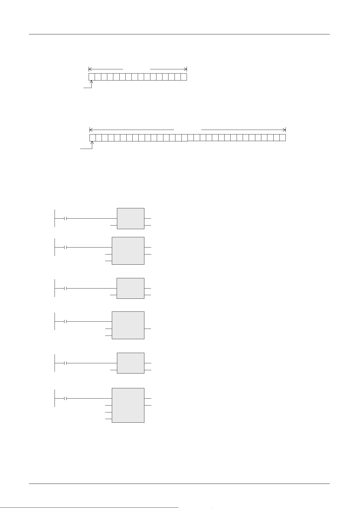
FXCPU Structured Programming Manual
r
[Device & Common]
1. Structure of the current value register of a counter
1) 16-bit
2 Devices in Detail
2.6 Counter [C]
2,048
4,096
16-bit
512
1,024
256
128
64
32
16
Available numeric value range
1010101010101010
b0
1
2
4
8
16-bit:0 to 32,767
32-bit:-2,147,483,648 to +2,147,483,647
High order Low order
b15
*1
Sign
0 : Positive
1 : Negative
*1.The sign is valid only when a timer is handled as a substitute for a data register.
8,192
16,384
2) 32-bit
131,072
262,144
524,288
32-bit
1010101010101010
65,536
16,384
32,768
4,096
8,192
1,024
2,048
512
256
128
64
32
16
Low orde
0000111100001111
1
2
4
8
High order
b31 b0
Sign
0 : Positive
1 : Negative
67,108,864
134,217,728
268,435,456
536,870,912
1,073,741,824
16,777,216
33,554,432
2,097,152
4,194,304
8,388,608
1,048,576
2. Use examples in applied instructions
For the full use of counters as numeric devices, refer to the instruction explanation manual offered separately.
→ FX Structured Programming Manual [Basic & Applied Instruction]
MOV
CN20
K100
CN30
ENsENO
CMP
EN
s1
s2
ENO
d
D10
d
M0
CN20 (current value) is transferred to D10.
A decimal integer "100" is compared with CN30
(current value), and the comparison result is
output to M0 to M2.
CN10
CN5
K2
CN200
K100
K20000
CN200
BCD
ENsENO
MUL_E
EN
_IN
_IN
DMOV
ENsENO
DZCP
EN
s1
s2
s3
ENO
ENO
The contents of CN10 (current value) are converted
into BCD, and output to Y000 to Y007
d
K2Y000
D4
d
D0
d
M10
(to control the 7-segment display unit).
CN5 (current value) is multiplied by "2", and the
obtained value is transferred to (D5, D4).
CN200 (current value) is transferred to (D1, D0).
CN200 (current value) is compared with a decimal
integer zone "100 to 20000", and the comparison
result is output to M10 to M12.
60
Page 63
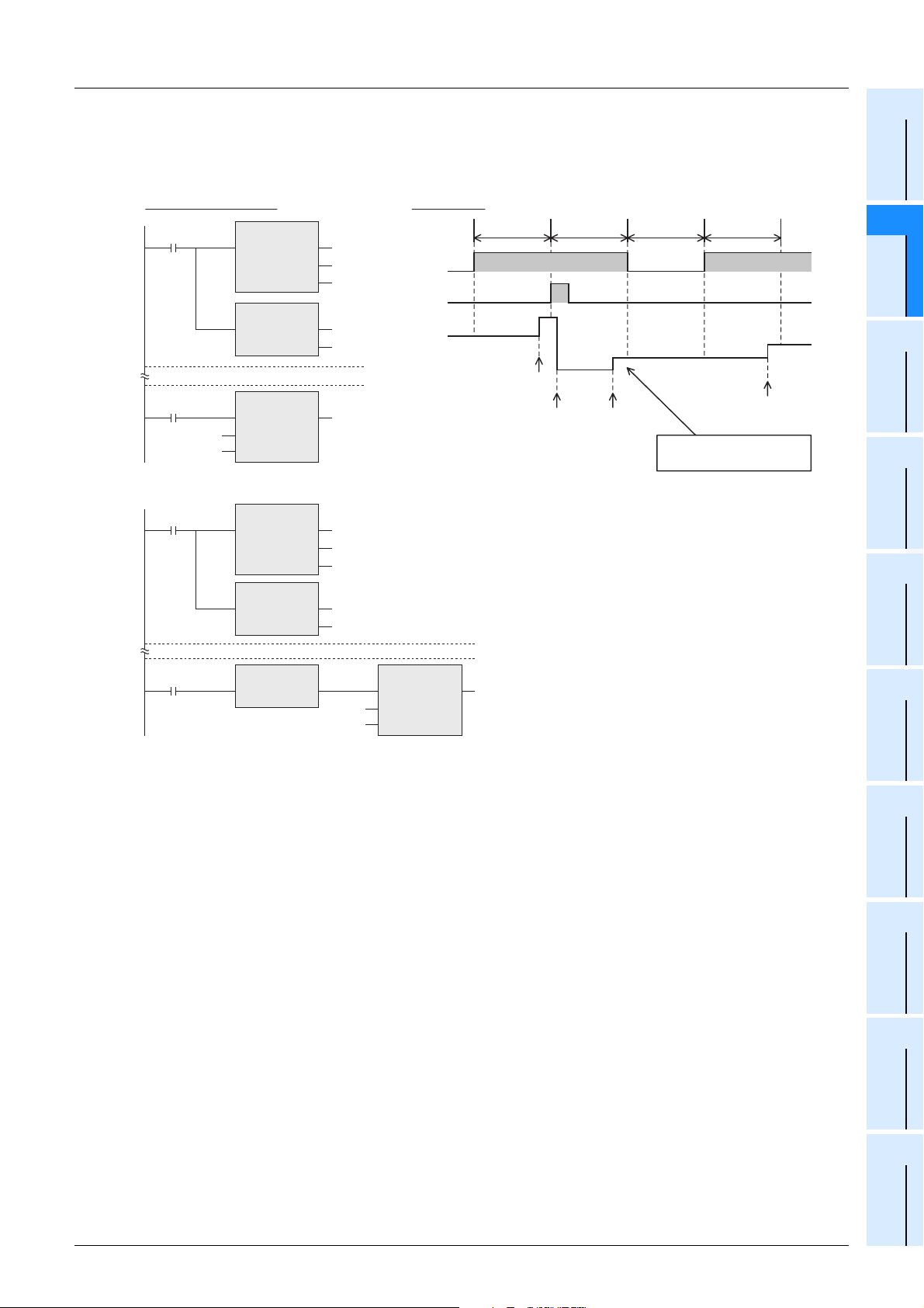
FXCPU Structured Programming Manual
[Device & Common]
3. Caution on simultaneous instances of the ZRST instruction and a counter
The ZRST instruction resets also the last stage and reset state of T and C coils.
Accordingly, if the drive contact of X000 is ON in the following program, the counter executes counting after
the ZRST instruction is executed.
Structured ladder/FBD
M0
X000
CC0
K10
ZRST
EN ENO
d1
d2
RST
EN ENO
OUT_C
EN ENO
CCoil
CValue
C0
C100
M0
d
Program in the following way to disable counting after execution of the ZRST instruction.
Timing chart
X000
M0
Current
value of C0
one operation
cycle
3
OUT_C instruction
execution
ZRST instruction
execution
one operation
cycle
4
0
OUT_C instruction
execution
one operation
cycle
1
2 Devices in Detail
2.6 Counter [C]
one operation
cycle
2
OUT_C instruction
execution
Counting is executed
when X000 is ON.
Constant
1
Device Outline
2
Devices in
Detail
3
Specified the
Device &
4
Special Device
M0
X000
ZRST
EN ENO
d1
d2
RST
EN ENO
MEP
EN ENO
C0
C100
M0
d
OUT_C
EN ENO
CC0
CCoil
K10
CValue
5
Errors
6
Types and
Setting of
Parameters
7
Other Functions
61
Page 64
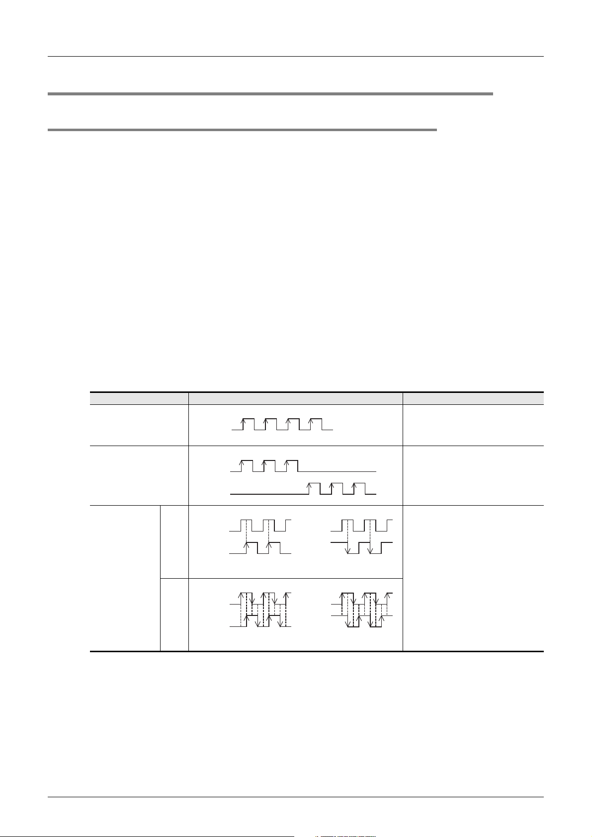
FXCPU Structured Programming Manual
[Device & Common]
2.7 High Speed Counter [C]
2.7.1 Types and device numbers of high speed counters
1. Types of high speed counters
The PLC main unit has built-in 32-bit high speed bidirectional counters (1-phase 1-counting, 1-phase 2counting and 2-phase 2-counting). These high speed counters are classified into the hardware type and the
software type according to the counting method.
Some high speed counters can be used together with an external reset input terminal and external start input
terminal (for counting start).
2. Classification of high speed counters according to the counting method
• Hardware counters :These types of counters execute counting using hardware, but are switched to
software counters depending on the operation condition.
→ For the condition handled as software counters, refer to Subsection 2.7.9.
• Software counters : These types of counters execute counting through CPU interrupt processing.
It is necessary to use each software counter within restrictions of both the maximum
response frequency and the total frequency.
→ For restriction of the response frequency depending on the total frequency, refer to Subsection
2 Devices in Detail
2.7 High Speed Counter [C]
2.7.10.
3. Types of high speed counters and input signal forms
The table below shows the types (1-phase 1-counting, 1-phase 2-counting and 2-phase 2-counting) and input
signals (waveforms) of high speed counters.
Input signal form Counting direction
The ON/OFF status of M8235 to M8245
1-phase 1-counting input
1-phase 2-counting input
2-phase 2-counting
input
UP/DOWN
1-edge counting
4-edge counting
UP
DOWN
Phase A
Phase B
Phase A
Phase B
+1 +1 +1
+1
+1
Up-counting
+1 +1 +1 +1 +1
+1 +1 +1 +1
Up-counting
-1 -1 -1
Phase A
Phase B
Phase A
Phase B
-1
-1
Down-counting
-1 -1 -1 -1 -1
-1 -1 -1 -1
Down-counting
specifies down-counting or up-counting.
ON: Down-counting
OFF: Up-counting
A counter executes up-counting or downcounting as shown on the left.
The counting direction can be checked in
M8246 to M8250.
ON: Down-counting
OFF: Up-counting
A counter automatically executes upcounting or down-counting according to
changes in the input status of the phase
A or B as shown on the left.
The counting direction can be checked in
M8251 to M8255.
ON: Down-counting
OFF: Up-counting
62
Page 65
FXCPU Structured Programming Manual
[Device & Common]
4. Cautions on counterpart equipment connected to high speed counter inputs
General-purpose inputs X000 to X007 (X003) are used for high speed counter inputs. An encoder*1 adopting
the output type shown in the table below can be connected depending on the connected terminal.
Encoders adopting the voltage output type and absolute encoders cannot be connected to high speed
counter inputs.
→ For the wiring, refer to the manual (Hardware Edition) of the PLC main unit.
2 Devices in Detail
2.7 High Speed Counter [C]
1
Device Outline
2
Devices in
Detail
Output type which can be directly connected to input terminal of
main unit
Output type which can be directly connected to input terminal of
FX3U-4HSX-ADP
*1. A rotary encoder adopting the output type shown above may not operate correctly depending on the
electrical compatibility. Check the specifications before connecting an encoder.
*2. This product is the adaptor for high speed input dedicated to FX
*2
Open collector transistor output type compatible with 24 VDC
Differential line driver output type (Output voltage: 5 VDC or less)
3U PLCs.
Constant
Parameters
3
Specified the
Device &
4
Special Device
5
Errors
6
Types and
Setting of
7
Other Functions
63
Page 66
FXCPU Structured Programming Manual
[Device & Common]
5. High speed counter list
1) In FX3U/FX3UC PLCs
2 Devices in Detail
2.7 High Speed Counter [C]
Classification Counter No.
Hardware
*1
counters
C244(OP)
C245(OP)
1-phase 1-counting input
Software
counters
Hardware
*1
1-phase 2-counting input
2-phase 2-counting input
counters
Software
counters
Hardware
counters
Software
counters
C248(OP)
*1
C253(OP)
C235
C236
C237
C238
C239
C240
C241
C242
C243
C244
C245
C246
C247
C248
C249
C250
C251
C253
C252
C254
C255
1-edge counting/
4-edge counting
*2
*2
*2
*2
*2
*2
*3
*3
*3
*3
*2
*2*3
*3
*2
*2
*6
-
-
-
-
-
-
-
1-edge counting
4-edge counting
1-edge counting
4-edge counting
1-edge counting
4-edge counting
1-edge counting
4-edge counting
1-edge counting
4-edge counting
*4
*4
*4
*4
*4
*4
*4
*4
*4
*4
Data length
32-bit
bidirectional
counter
32-bit
bidirectional
counter
32-bit
bidirectional
counter
External reset input
terminal
Not provided Not provided
*5
Provided
*5
Provided
Not provided Not provided
*5
Provided
*5
Provided
Not provided
*5
Provided
*5
Provided
Not provided
*5
Provided
External start input
Not provided
Provided
Not provided
Provided
Not provided
Not provided
Provided
terminal
64
*1. They are handled as software counters depending on the operating condition. When they are handled
as software counters, they get restrictions of both the maximum response frequency and the total
frequency.
→ For the condition handled as software counters, refer to Subsection 2.7.9.
→ For the total frequency, refer to Subsection 2.7.10.
*2. Cautions on wiring should be considered for these high speed counters.
→ For the wiring, refer to the manual (Hardware Edition) of the PLC main unit.
*3. C244, C245 and C248 are usually used as software counters, but can be used as hardware counters
C244 (OP), C245 (OP) and C248 (OP) by combining special auxiliary relays (M8388 and one among
M8390 to M8392).
→ For the method to switch the counter function, refer to Subsection 2.7.7.
*4. 2-phase 2-input counters usually execute 1-edge counting, but can be used for 4-edge counting by
combining special auxiliary relays (M8388 and one between M8198 and M8199).
→ For the method to use a 2-phase 2-input counter for 4-edge counting, refer to Subsection 2.7.8.
*5. The external reset input usually causes reset at turning ON, but can cause reset at turning OFF by
combining special auxiliary relays (M8388 and M8389).
→ For the method to change the logic for external reset input, refer to Subsection 2.7.6.
*6. C253 is usually used as a hardware counter, but can be used as a counter C253 (OP) not having
reset input by combining special auxiliary relays (M8388 and M8392).
In this case, C253 (OP) is handled as a software counter.
Page 67
FXCPU Structured Programming Manual
[Device & Common]
Notation of high speed counters
2 Devices in Detail
2.7 High Speed Counter [C]
1
Device Outline
For some high speed counters in FX
3U/FX3UC PLCs, the assignment of input terminals switches when special
auxiliary relays are combined.
(For input terminal numbers, refer to Subsection 2.7.2.)
Such high speed counters are described as follows in this section. Note that "(OP)" is not available in
programming.
Standard device number Switched device number Standard device number Switched device number
C244 C244(OP) C248 C248(OP)
C245 C245(OP) C253 C253(OP)
2) In FX
3G/FX3GC PLCs
Classification Counter No.
Software
counters
1-phase 1-counting input
C248(OP)
Software
counters
1-phase 2-counting input
C253(OP)
C254(OP)
Software
counters
2-phase 2-counting input
C235
C236
C237
C238
C239
C240
C241
C242
C243
C244
C245
C246
C247
C248
C249
C250
C251
C252
C253
C254
C255
1-edge counting/
4-edge counting
-
- Provided Not provided
- Provided Provided
*1
*1
*2
-
- Provided Not provided
- Provided Provided
1-edge counting
1-edge counting Provided Not provided
1-edge counting Provided Provided
Data length
32-bit
bidirectional
counter
32-bit
bidirectional
counter
32-bit
bidirectional
counter
External reset input
terminal
Not provided Not provided
Not provided Not provided
Not provided Not provided
External start input
terminal
2
Devices in
Detail
3
Specified the
Device &
Constant
4
Special Device
5
Errors
6
Types and
Setting of
Parameters
7
Other Functions
*1. C248 and C253 are usually used as counters having reset input, but can be used as counters C248
(OP) and C253 (OP) not having reset input when used together with special auxiliary relays M8388
and M8392.
*2. C254 is usually used as a counter having reset input and start input, but can be used as a counter
C254 (OP) not having reset input or start input when used together with special auxiliary relays M8388
and M8395.
Notation of high speed counters
For some high speed counters in FX
3G/FX3GC PLCs, the assignment of input terminals switches when
special auxiliary relays are combined.
Such high speed counters are described as follows in this section. Note that "(OP)" is not available in
programming.
Standard device number Switched device number
C248 C248(OP)
C253 C253(OP)
C254 C254(OP)
65
Page 68
FXCPU Structured Programming Manual
[Device & Common]
3) In FX3S PLC
Classification Counter No.
C235
C236
C237
C238
Software
counters
1-phase 1-counting input
Software
counters
1-phase 2-counting input
Software
counters
2-phase 2-counting input
C239
C240
C241
C242
C243
C244
C245
C246
C248(OP)
C247
C248
C249
C250
C251
C253(OP)
C252
C253
C254
C255
*1
*1
2 Devices in Detail
2.7 High Speed Counter [C]
1-edge counting/
4-edge counting
-
- Provided Not provided
- Provided Provided
-
- Provided Not provided
- Provided Provided
1-edge counting
1-edge counting Provided Not provided
1-edge counting Provided Provided
Data length
32-bit
bidirectional
counter
32-bit
bidirectional
counter
32-bit
bidirectional
counter
External reset input
terminal
Not provided Not provided
Not provided Not provided
Not provided Not provided
External start input
terminal
*1. C248 and C253 are usually used as counters having reset input, but can be used as counters C248
(OP) and C253 (OP) not having reset input when used together with special auxiliary relays M8388
and M8392.
Notation of high speed counters
For some high speed counters in FX
3S PLC, the assignment of input terminals switches when special
auxiliary relays are combined.
Such high speed counters are described as follows in this section. Note that "(OP)" is not available in
programming.
Standard device number Switched device number
C248 C248(OP)
C253 C253(OP)
66
Page 69
FXCPU Structured Programming Manual
[Device & Common]
4) In FX1S/FX1N/FX1NC PLCs
2 Devices in Detail
2.7 High Speed Counter [C]
1
Device Outline
Classification Counter No.
Software
counters
1-phase 1-counting input
Software
counters
1-phase 2-counting input
Software
counters
2-phase 2-counting input
1-edge counting/
4-edge counting
C235
C236
C237
C238
C239
C240
C242
C243
C244
C245
C246 -
C247
C248
C249
C250
C251
C252
C253
C254
C255
1-edge counting
Data length
-
32-bit
bidirectional
-C241
-Provided
counter
32-bit
bidirectional
counter
32-bit
bidirectional
counter
External reset input
terminal
Not provided
Provided
Not provided
Not provided
Provided
External start input
terminal
Not provided
Provided
Not provided
Provided
Not provided
Provided
Constant
2
Devices in
Detail
3
Specified the
Device &
4
Special Device
5
Errors
5) In FX
2N/FX2NC PLCs
Classification Counter No.
counters
1-phase 1-counting input
counters
1-phase 2-counting input
counters
2-phase 2-counting input
Hardware
Software
counters
Hardware
Software
counters
Hardware
Software
counters
1-edge counting/
4-edge counting
*1
*1
*1
C235
C236
C237
C238
C239
C240
C242
C243
C244
C245
C246 -
C247
C248
C249
C250
C251
C252
C253
C254
C255
-
-C241
-Provided
1-edge counting
Data length
32-bit
bidirectional
counter
32-bit
bidirectional
counter
32-bit
bidirectional
counter
External reset input
terminal
Not provided
Provided
Not provided
Not provided
Provided
External start input
terminal
Not provided
Provided
Not provided
Provided
Not provided
Provided
6
Types and
Setting of
Parameters
7
Other Functions
*1. They are handled as software counters depending on the operating condition. When they are handled
as software counters, they get restrictions of both the maximum response frequency and the total
frequency.
67
Page 70
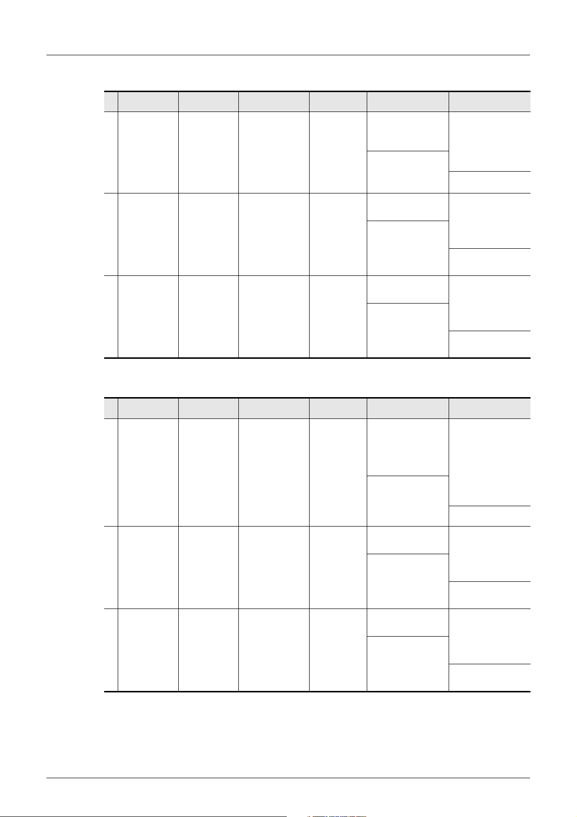
FXCPU Structured Programming Manual
[Device & Common]
6) In FX0S/FX0/FX0N PLCs
2 Devices in Detail
2.7 High Speed Counter [C]
Classification Counter No.
Software
counters
1-phase 1-counting input
Software
counters
1-phase 2-counting input
Software
counters
2-phase 2-counting input
1-edge counting/
4-edge counting
C235
C236
C237
C238
C241
C242
C244 Provided
C246
C247
C249 Provided
C251
C252
C254 Provided
-
-
1-edge counting
Data length
32-bit
bidirectional
counter
32-bit
bidirectional
counter
32-bit
bidirectional
counter
External reset input
terminal
Not provided
Provided
Not provided
Provided
Not provided
Provided
External start input
terminal
Not provided
Not provided
Not provided
7) In FX
1-phase 1-counting input
1-phase 2-counting input
2-phase 2-counting input
U/FX2C PLCs
Classification Counter No.
C235
C236
C237
C238
Software
counters
Software
counters
Software
counters
C239
C240
C241
C242
C243
C244
C245
C246
C247
C248
C249
C250
C251
C252
C253
C254
C255
1-edge counting/
4-edge counting
-
-
1-edge counting
Data length
32-bit
bidirectional
counter
32-bit
bidirectional
counter
32-bit
bidirectional
counter
External reset input
terminal
Not provided
Provided
Not provided
Provided
Not provided
Provided
External start input
terminal
Not provided
Provided
Not provided
Provided
Not provided
Provided
68
Page 71

FXCPU Structured Programming Manual
[Device & Common]
2.7.2 Input assignment for high speed counters
Inputs X000 to X007 (X003) are assigned as shown in the tables below according to each high speed counter
number.
When a high speed counter is used, the filer constant of a corresponding input number in the PLC main unit
automatically changes.
Input terminals not used for high speed counters, however, can be used as general inputs.
→ For the input specifications of the PLC main unit, refer to the hardware manual of the PLC main
FX
3U/FX3UC PLCs : (X000 to X005:5μS, X006, X007:50μS)
3G/FX3GC PLCs : (X000, X001, X003, X004:10μS, X002, X005 to X007:50μS)
FX
3S PLC : (X000, X001:10μS, X002 to X007:50μS)
FX
1S/FX1N/FX1NC/FX2N/FX2NC PLCs : (X000, X001:20μS, X002 to X005:50μS)
FX
0S/FX0/FX0N/FXU/FX2C PLCs : (X000 to X003/X005:50μS)
FX
• Prohibition on redundant use of input terminals
Inputs X000 to X007(X003) are used for high speed counters, input interrupt, pulse catch, SPD/DSZR/
DVIT/ZRN instructions and general-purpose inputs.
Make sure to use each input terminal only once.
2 Devices in Detail
2.7 High Speed Counter [C]
unit.
Constant
1
Device Outline
2
Devices in
Detail
3
Specified the
Device &
4
Special Device
5
Errors
6
Types and
Setting of
Parameters
7
Other Functions
69
Page 72
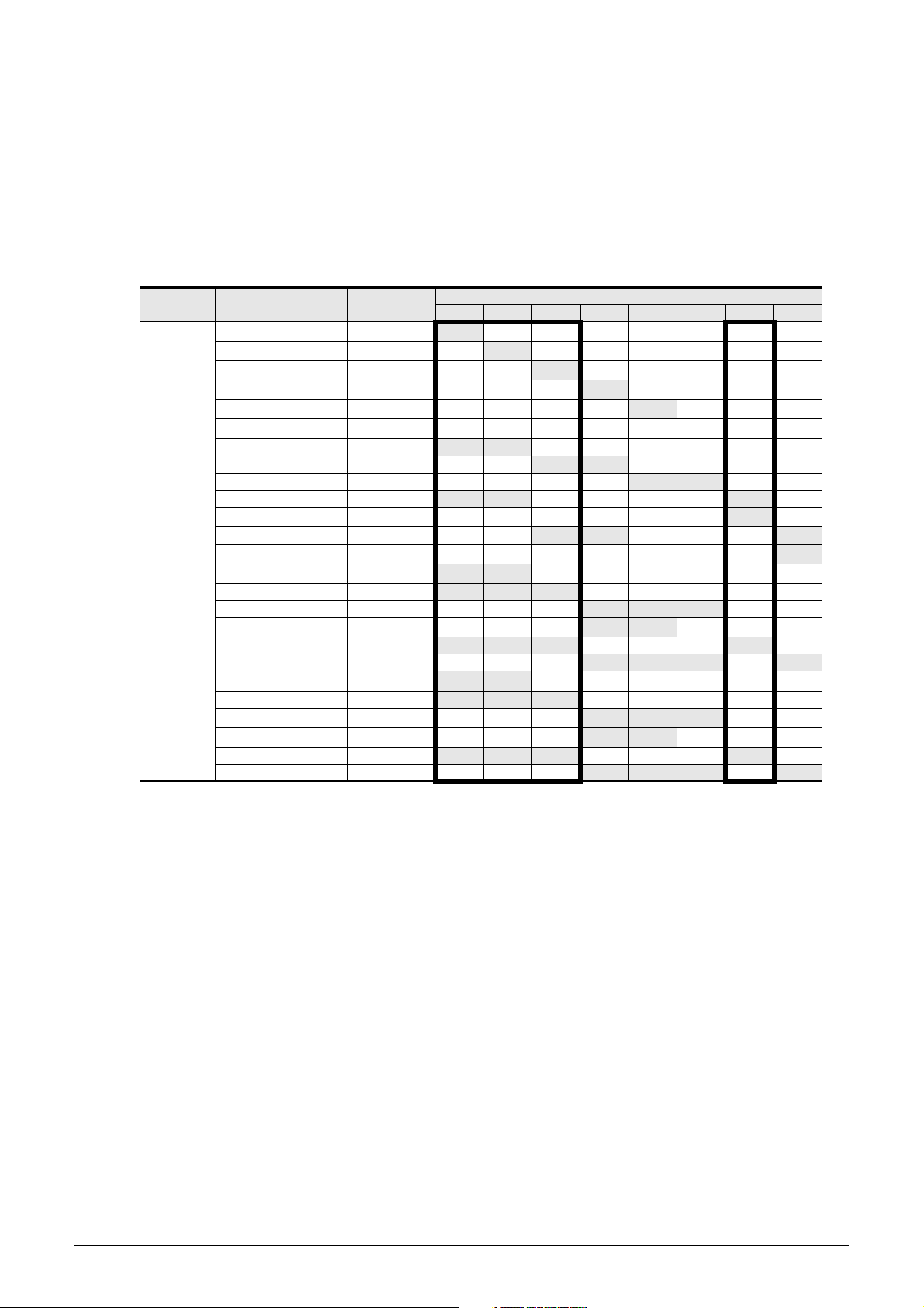
FXCPU Structured Programming Manual
[Device & Common]
1. In FX3U/FX3UC PLCs
When FX3U-4HSX-ADP units are connected to an FX3U PLC, input terminals inside heavy-line frames in the
table below are assigned to the first FX
second FX
Same input numbers are assigned to input terminals of the FX
PLC main unit. Use only either input terminal.
If both input terminals are used, intended operations are not achieved because inputs of the FX
and inputs of the FX
1-phase
1-counting
1-phase
2-counting
2-phase
2-counting
H/W : Hardware counters S/W : Software counters U : Up-counting input D : Down-counting input
A : Phase A input B : Phase B input R : External reset input S : External start input
*1. Cautions on wiring should be considered for these high speed counters.
*2. Hardware counters are switched to software counters when a comparison set/reset instruction for high
*3. When a special auxiliary relay is driven in a program, used input terminals and their functions are
*4. 2-phase 2-input counters usually execute 1-edge counting, but can be used for 4-edge counting by
3U-4HSX-ADP unit.
3U PLC operate under the "OR" relationship.
→ For the input specifications of the FX
Counter No. Classification
*1
input
input
input
C235
*1
C236
*1
C237
*1
C238
*1
C239
*1
C240
C241 S/W
C242 S/W
C243 S/W U/D R
C244 S/W U/D R S
C244(OP)
C245(OP)
C248(OP)
C253(OP)
*3
C245 S/W U/D R S
*3
*1
C246
C247 S/W U D R
C248 S/W U D R
*1*3
C249 S/W U D R S
C250 S/W U D R S
*1
C251
C252 S/W A B R
*1
C253
*3
C254 S/W A B R S
C255 S/W A B R S
H/W
H/W
H/W
H/W
H/W
H/W
H/W
H/W
H/W
H/W
H/W
H/W
S/W A B
→ For the wiring, refer to the hardware manual of the PLC main unit.
speed counter (DHSCS, DHSCR, DHSZ or DHSCT) is used.
C253 is switched to a software counter when the logic for external reset input is reversed.
→ For the condition under which hardware counters are handled as software counters, refer to
switched.
→ For the method to use software counters as hardware counters, refer to Subsection 2.7.7.
combining special auxiliary relays.
→ For the method to use a 2-phase 2-input counter for 4-edge counting, refer to Subsection 2.7.8.
2 Devices in Detail
2.7 High Speed Counter [C]
3U-4HSX-ADP unit, and other input terminals are assigned to the
3U-4HSX-ADP and input terminals of the FX3U
3U-4HSXADP
3U-4HSX-ADP, refer to the FX3U hardware manual.
Input terminal assignment
X000 X001 X002 X003 X004 X005 X006 X007
*2
*2
*2
*2
*2
*2
*2
*2
*2
*2
*2
*2
U/D
U/D
U/D
U/D
U/D
U/D
U/D R
U/D R
U/D
U/D
U D
U D
A B
A B R
Subsection 2.7.9.
70
Page 73
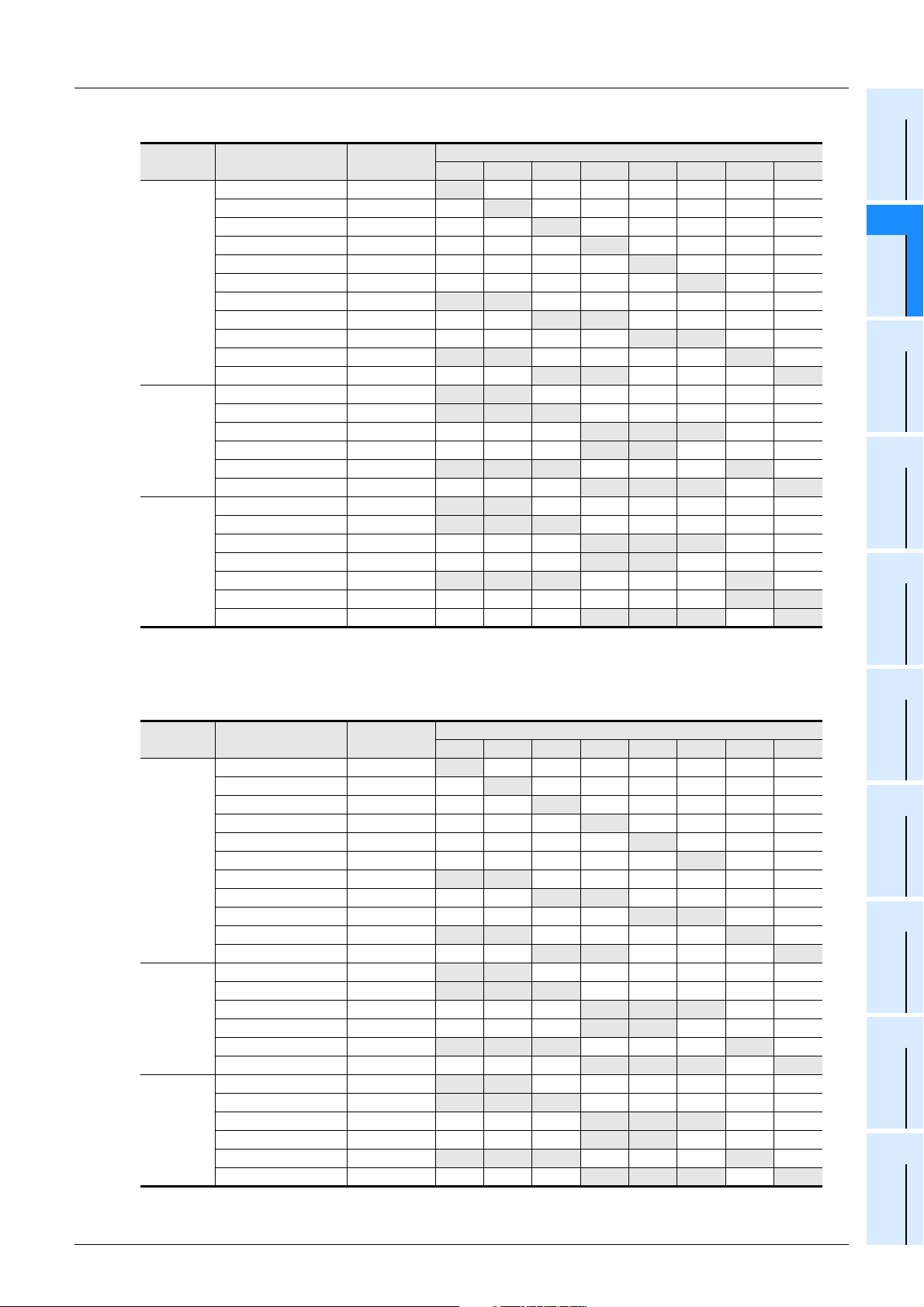
FXCPU Structured Programming Manual
[Device & Common]
2. In FX3G/FX3GC PLCs
Counter No. Classification
C235 S/W U/D
C236 S/W U/D
C237 S/W U/D
C238 S/W U/D
1-phase
1-counting
input
1-phase
2-counting
input
2-phase
2-counting
input
H/W : Hardware counters S/W : Software counters U : Up-counting input D : Down-counting input
A : Phase A input B : Phase B input R : External reset input S : External start input
C239 S/W U/D
C240 S/W U/D
C241 S/W U/D R
C242 S/W U/D R
C243 S/W U/D R
C244 S/W U/D R S
C245 S/W U/D R S
C246 S/W U D
C247 S/W U D R
C248 S/W U D R
C248(OP) S/W U D
C249 S/W U D R S
C250 S/W U D R S
C251 S/W A B
C252 S/W A B R
C253 S/W A B R
C253(OP) S/W A B
C254 S/W A B R S
C254(OP) S/W A B
C255 S/W A B R S
2 Devices in Detail
2.7 High Speed Counter [C]
Input terminal assignment
X000 X001 X002 X003 X004 X005 X006 X007
Constant
1
Device Outline
2
Devices in
Detail
3
Specified the
Device &
4
Special Device
5
Errors
3. In FX3S PLC
Input terminal assignment
1-phase
1-counting
input
1-phase
2-counting
input
2-phase
2-counting
input
Counter No. Classification
C235 S/W U/D
C236 S/W U/D
C237 S/W U/D
C238 S/W U/D
C239 S/W U/D
C240 S/W U/D
C241 S/W U/D R
C242 S/W U/D R
C243 S/W U/D R
C244 S/W U/D R S
C245 S/W U/D R S
C246 S/W U D
C247 S/W U D R
C248 S/W U D R
C248(OP) S/W U D
C249 S/W U D R S
C250 S/W U D R S
C251 S/W A B
C252 S/W A B R
C253 S/W A B R
C253(OP) S/W A B
C254 S/W A B R S
C255 S/W A B R S
X000 X001 X002 X003 X004 X005 X006 X007
H/W : Hardware counters S/W : Software counters U : Up-counting input D : Down-counting input
A : Phase A input B : Phase B input R : External reset input S : External start input
6
Types and
Setting of
Parameters
7
Other Functions
71
Page 74
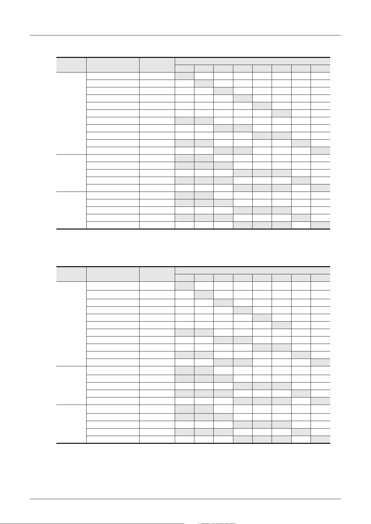
FXCPU Structured Programming Manual
[Device & Common]
4. In FX1S/FX1N/FX1NC PLCs
Counter No. Classification
C235 S/W U/D
C236 S/W U/D
C237 S/W U/D
C238 S/W U/D
1-phase
1-counting
input
1-phase
2-counting
input
2-phase
2-counting
input
H/W : Hardware counters S/W : Software counters U : Up-counting input D : Down-counting input
A : Phase A input B : Phase B input R : External reset input S : External start input
C239 S/W U/D
C240 S/W U/D
C241 S/W U/D R
C242 S/W U/D R
C243 S/W U/D R
C244 S/W U/D R S
C245 S/W U/D R S
C246 S/W U D
C247 S/W U D R
C248 S/W U D R
C249 S/W U D R S
C250 S/W U D R S
C251 S/W A B
C252 S/W A B R
C253 S/W A B R
C254 S/W A B R S
C255 S/W A B R S
2 Devices in Detail
2.7 High Speed Counter [C]
Input terminal assignment
X000 X001 X002 X003 X004 X005 X006 X007
5. In FX2N/FX2NC PLCs
Input terminal assignment
Subsection 2.7.9.
1-phase
1-counting
input
1-phase
2-counting
input
2-phase
2-counting
input
Counter No. Classification
C235
C236
C237 S/W U/D
C238 S/W U/D
C239 S/W U/D
C240 S/W U/D
C241 S/W U/D R
C242 S/W U/D R
C243 S/W U/D R
C244 S/W U/D R S
C245 S/W U/D R S
C246
C247 S/W U D R
C248 S/W U D R
C249 S/W U D R S
C250 S/W U D R S
C251
C252 S/W A B R
C253 S/W A B R
C254 S/W A B R S
C255 S/W A B R S
H/W
H/W
H/W
H/W
*1
*1
*1
*1
X000 X001 X002 X003 X004 X005 X006 X007
U/D
U/D
U D
A B
H/W : Hardware counters S/W : Software counters U : Up-counting input D : Down-counting input
A : Phase A input B : Phase B input R : External reset input S : External start input
*1. Hardware counters are switched to software counters when a comparison set/reset instruction for high
speed counter (DHSCS, DHSCR or DHSZ) is used.
→ For the condition under which hardware counters are handled as software counters, refer to
72
Page 75
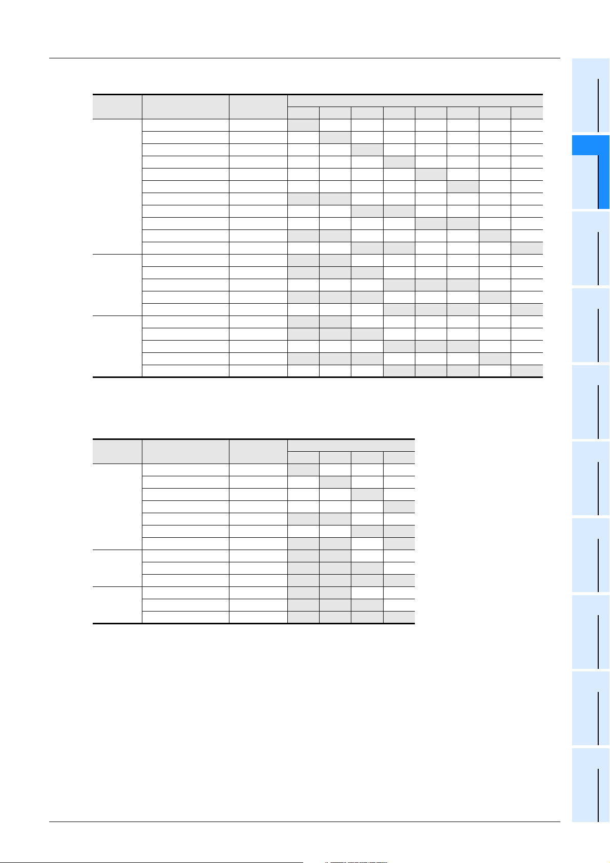
FXCPU Structured Programming Manual
[Device & Common]
6. In FXU/FX2C PLCs
Counter No. Classification
C235 S/W U/D
C236 S/W U/D
C237 S/W U/D
C238 S/W U/D
1-phase
1-counting
input
1-phase
2-counting
input
2-phase
2-counting
input
H/W : Hardware counters S/W : Software counters U : Up-counting input D : Down-counting input
A : Phase A input B : Phase B input R : External reset input S : External start input
C239 S/W U/D
C240 S/W U/D
C241 S/W U/D R
C242 S/W U/D R
C243 S/W U/D R
C244 S/W U/D R S
C245 S/W U/D R S
C246 S/W U D
C247 S/W U D R
C248 S/W U D R
C249 S/W U D R S
C250 S/W U D R S
C251 S/W A B
C252 S/W A B R
C253 S/W A B R
C254 S/W A B R S
C255 S/W A B R S
2 Devices in Detail
2.7 High Speed Counter [C]
Input terminal assignment
X000 X001 X002 X003 X004 X005 X006 X007
Constant
1
Device Outline
2
Devices in
Detail
3
Specified the
Device &
4
Special Device
5
Errors
7. In FX0S/FX0/FX0N PLCs
Counter No. Classification
C235 S/W U/D
C236 S/W U/D
1-phase
1-counting
input
1-phase
2-counting
input
2-phase
2-counting
input
C237 S/W U/D
C238 S/W U/D
C241 S/W U/D R
C242 S/W U/D R
C244 S/W U/D R S
C246 S/W U D
C247 S/W U D R
C249 S/W U D R S
C251 S/W A B
C252 S/W A B R
C254 S/W A B R S
H/W : Hardware counters S/W : Software counters U : Up-counting input D : Down-counting input
A : Phase A input B : Phase B input R : External reset input S : External start input
Input terminal assignment
X000 X001 X002 X003
6
Types and
Setting of
Parameters
7
Other Functions
73
Page 76
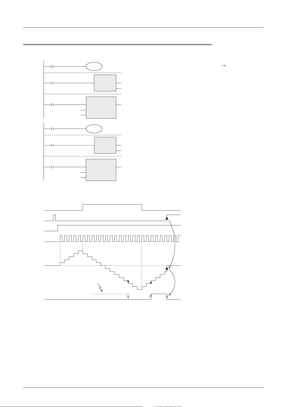
FXCPU Structured Programming Manual
[Device & Common]
2.7.3 Handling of high speed counters
1. 1-phase 1-counting input
X010
M8235
X011
Down-counting
or up-counting
RST
EN ENO
d
CC235
2 Devices in Detail
2.7 High Speed Counter [C]
·
While X012 is ON, C235 counts "OFF ON"
of the input X000.
·
When X011 turns ON and then the RST instruction
is executed, C235 is reset.
X012
CC235
K-5
X010
X011
X012
CC244
D0
OUT_C_32
EN ENO
CCoil
CValue
M8244
OUT_C_32
EN ENO
CCoil
CValue
Down-counting
or up-counting
RST
EN ENO
d
CC244
Operation example
The counter C235 shown above operates as follows:
X010
X011
X012
X000
Counting
input
C235
Current
value
Up-counting
Reset input
Start input
3
2
1
0
454
3
2
1
Down-counting
0
Up-counting
The counting direction of counters C235 to C245
·
is switched to down-counting or up-counting
when M8235 to M8245 turns ON or OFF.
·
While X012 is ON, C244 immediately starts counting
when the input X006 turns ON. The counting input
is X000.
In this example, the set value is indirectly
specified as the contents of data registers (D1, D0).
The high speed counter C244 can be reset using X011
·
in a sequence as shown in the figure, but it is
immediately reset without any program when X001
is closed.In this case, any program including X011
is not necessary.
The counting direction of counters C235 to C245
·
is switched to down-counting or up-counting
when M8235 to M8245 turns ON or OFF.
0
74
-1
-2
When output has been
already turned ON
C235 output contact
-3
-4
-5
-6
-7
-7
-8
-3
-4
-5
-6
When the counting input X000 is given, C235 executes up-counting or down-counting as interrupt processing.
• When the current value of the counter increases from "-6" to "-5", the output contact is set (turned ON).
When the current value decreases from "-5" to "-6", the output contact is reset (turned OFF).
• The current value increases or decreases without regard to the operation of the output contact.
When the counter executes up-counting from "+2,147,483,647", the count value becomes "2,147,483,648". In the same way, when the counter executes down-counting from "-2,147,483,648", the
count value becomes "+2,147,483,647". (This type of operation is called ring counter.)
• When the reset input X011 turns ON and then the RST instruction is executed, the current value of the
counter is reset to "0" and the output contact is turned OFF.
• In a latched type high speed counter, the current value, output contact operation status and reset status of
the counter are latched (backed up) even if the power is interrupted.
Page 77
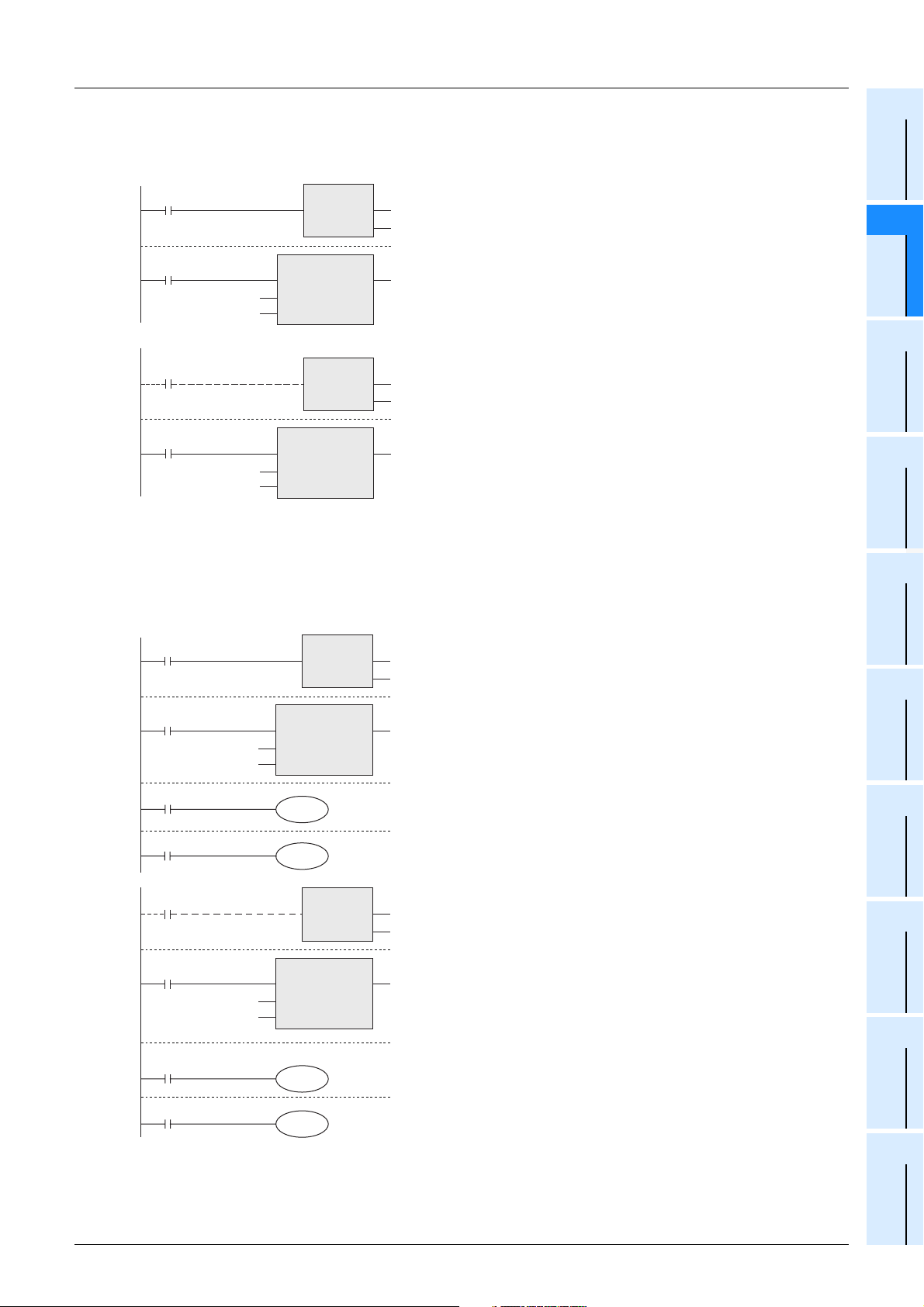
FXCPU Structured Programming Manual
[Device & Common]
2. 1-phase 2-counting input
These counters are 32-bit bidirectional counters. The operation of the output contact caused by the current
value is equivalent to that in 1-phase 1-counting input type high speed counters described above.
X011
RST
EN ENO
d
CC246
2 Devices in Detail
2.7 High Speed Counter [C]
·
While X012 is ON, C246 executes up-counting when
the input X000 turns ON from OFF, and executes
down-counting when the input X001 turns ON from OFF.
1
Device Outline
2
Devices in
Detail
X012
X011
X012
CC246
D2
CC249
K1234
OUT_C_32
EN ENO
CCoil
CValue
RST
EN ENO
OUT_C_32
EN ENO
CCoil
CValue
d
CC249
·
The up/down-counting operation of C246 to C250 is
indicated by the ON/OFF status of M8246 to M8250.
ON: Down-counting
OFF: Up-counting
·
While X012 is ON, C249 immediately starts counting
when the input X006 (X003) turns ON.
The up-counting input is X000, and the down-counting
input is X001.
·
The high speed counter C244 can be reset using X011
in a sequence as shown in the figure, but it is
immediately reset without any program when X002 is
closed. In this case, any program including X011
is not necessary.
·
The up/down-counting operation of C246 to C250 is
indicated by the ON/OFF status of M8246 to M8250.
ON: Down-counting
OFF: Up-counting
These counters are 32-bit bidirectional counters. The operation of the output contact caused by the current
value is equivalent to that in 1-phase type high speed counters described above.
→ Refer to "2.7.2 Input assignment for high speed counters".
·
X011
X012
CS251
M8251
CC251
K1234
RST
EN ENO
OUT_C_32
EN ENO
CCoil
CValue
Y002
Y003
d
CC251
While X012 is ON, C251 counts operations of inputs
X000 (phase A) and X001 (phase B) as interrupt
processing.
When X011 turns ON and then the RST instruction is
execute, C251 is reset.
·
When the current value becomes equivalent to or
larger than the set value, Y002 turns ON. When the
current value becomes equivalent to or smaller than
the set value, Y002 turns OFF.
·
Y003 turns ON (for down-counting) or OFF
(for up-counting) according to the counting direction.
3
Specified the
Device &
Constant
4
Special Device
5
Errors
6
Types and
Setting of
Parameters
7
Other Functions
X011
X012
CS254
M8254
CC254
D0
RST
EN ENO
OUT_C_32
EN ENO
CCoil
CValue
Y004
Y005
·
While X012 is ON, C254 immediately starts counting
d
CC254
when the input X006 turns ON. Its counting inputs
are X000 (phase A) and X001 (phase B).
·
In addition to reset by X011 in a sequence, C254 is
immediately reset when X002 turns ON.
·
When the current value becomes equivalent to or larger
than the set value (D1, D0), Y004 turns ON. When the
current value becomes equivalent to or smaller than
the set value, Y004 turns OFF.
·
Y005 turns ON (for down-counting) or OFF
(for up-counting) according to the counting direction.
75
Page 78

FXCPU Structured Programming Manual
[Device & Common]
• 2-phase encoder generates outputs for the phase A and phase B with a phase difference of 90°. With
these outputs, a high speed counter automatically executes up-counting and down-counting as shown in
the figure below.
- When a counter is executing 1-edge counting
2 Devices in Detail
2.7 High Speed Counter [C]
Phase A
+1
Phase B
Up-counting
+1
Phase A
Phase B
-1
-1
Down-counting
- When a counter is executing 4-edge counting
Phase A
Phase B
+1 +1 +1 +1 +1
Phase A
Phase B
+1 +1 +1 +1
Up-counting
-1 -1 -1 -1 -1
-1 -1 -1 -1
Down-counting
• The up/down-counting operation of C251 to C255 is indicated by the ON/OFF status of M8251 to M8255.
ON: Down-counting
OFF: Up-counting
76
Page 79
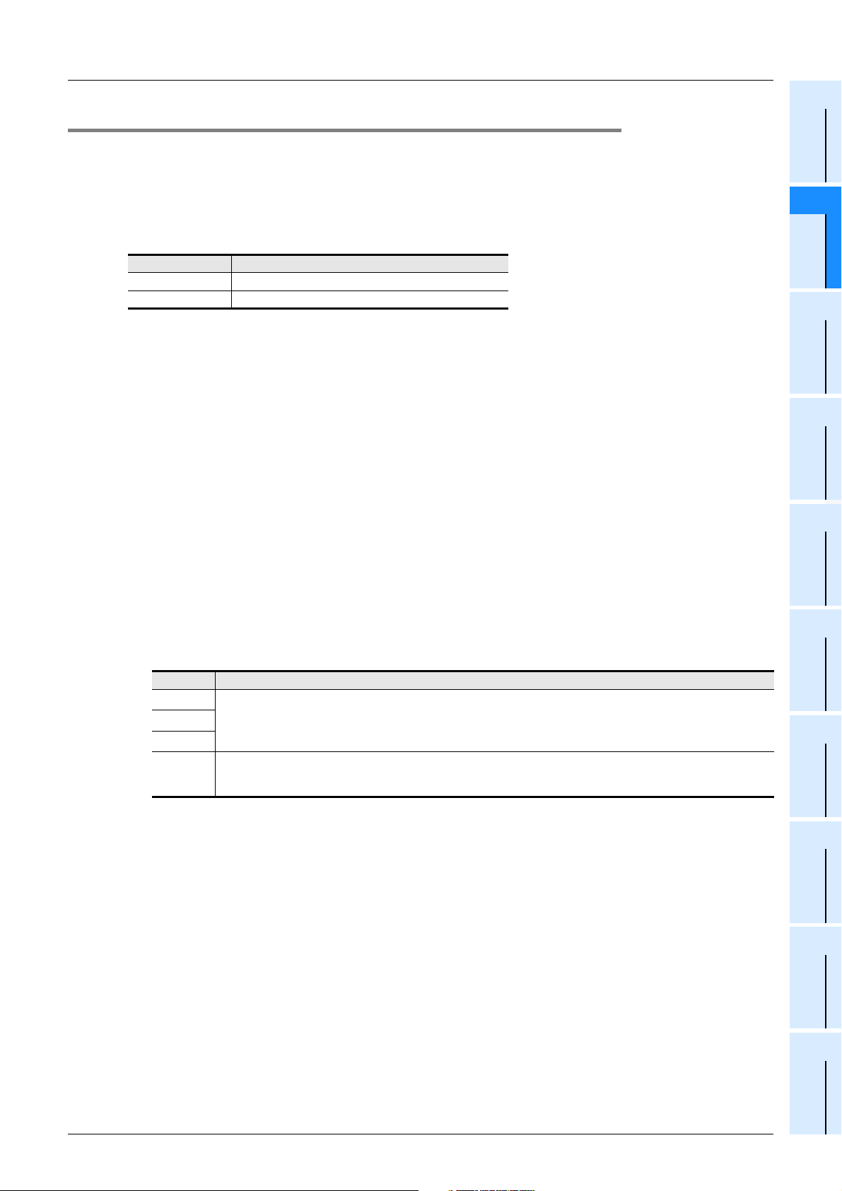
FXCPU Structured Programming Manual
[Device & Common]
2.7.4 Current value update timing and comparison of current value
1. Current value update timing
A high speed counter executes up-counting or down-counting when a pulse is input to its input terminal, but
the current value of the high speed counter is updated at the timing shown in the table below.
When the current value of a high speed counter is used as it is in the MOV instruction, CMP instruction or
applied instruction for data comparison, etc., the current value update timing is affected by scans as shown in
the table.
Current value update timing
Hardware counter When OUT or HCMOV instruction is executed for counter
Software counter When counting input is given
2. Comparison of the current value
The following two methods are available to compare and output the current value of a high speed counter.
Some instructions are not supported in some PLCs.
→ Refer to the FX Structured Programming Manual [Basic & Applied Instruction].
1) Using the comparison instruction (CMP), zone comparison instruction (ZCP) or data comparison
instruction
When the comparison result is not necessary during counting operation, comparison may be smoothly
executed in the main program
(CMP or ZCP) or data comparison instruction.
*1. If it is necessary to execute comparison and update an output contact (Y) at the timing at which the
current value of a high speed counter changes, use a comparison instruction for high speed counter
(DHSCS, DHSCR, DHSZ or DHSCT).
2) Using a comparison instruction for high speed counter (DHSCS, DHSCR, DHSZ or DHSCT)
A comparison instruction for high speed counter (DHSCS, DHSCR, DHSZ or DHSCT) executes
comparison and outputs the comparison result while the target high speed counter is counting.
The number of times of using these instructions is restricted as shown in the table below.
When an output relay (Y) is specified for the comparison result, the comparison result is directly reflected
on the ON/OFF status of the output without regard to output refresh executed by the END instruction.
Mechanical operation delay (about 10 ms) cannot be avoided in a relay output type PLC.
Use a transistor output type PLC.
Instruction Restriction of number of times of using instruction
*1
DHSCS
DHSCR
DHSZ
DHSCT
FX3U/FX3UC PLCs: These instructions can be used up to 32 times including the DHSCT instruction.
FX
0S/FX0/FX0N/FX1S/FX1N/FX1NC/FXU/FX2C/FX2N/FX2NC/FX3S/FX3G/FX3GC PLCs: These instructions can be
*1
used up to 6 times.
*1
*1
0S/FX0/FX0N/FX1S/FX1N/FX1NC PLCs do not support the DHSZ instruction.)
(FX
This instruction can be used only once.
(FX
0S/FX0/FX0N/FX1S/FX1N/FX1NC/FXU/FX2C/FX2N/FX2NC/FX3S/FX3G/FX3GC PLCs do not support the DHSCT
instruction.)
*1
if the DHCMOV instruction is used just before the comparison instruction
2 Devices in Detail
2.7 High Speed Counter [C]
1
Device Outline
2
Devices in
Detail
3
Specified the
Device &
Constant
4
Special Device
5
Errors
6
Types and
Setting of
Parameters
7
Other Functions
*1. When a comparison instruction for high speed counter is used, the maximum response frequency and
total frequency of software counters may be restricted.
→ For the maximum response frequency and total frequency of software counters, refer to
Subsection 2.7.10.
77
Page 80
FXCPU Structured Programming Manual
[Device & Common]
2 Devices in Detail
2.7 High Speed Counter [C]
2.7.5 Related devices
1. Devices used to switch the counting direction of 1-phase 1-counting input counters
Type Counter No. Specifying device Up-counting Down-counting
C235 M8235
C236 M8236
C237 M8237
C238 M8238
C239 M8239
1-phase 1-counting input
C240 M8240
C241 M8241
C242 M8242
C243 M8243
C244 M8244
C245 M8245
2. Devices used to monitor the counting direction of 1-phase 1-counting input counters and 2phase 2-counting input counters
Type Counter No. Monitoring device OFF ON
C246 M8246
C247 M8247
1-phase 1-counting input
2-phase 2-counting input
C248 M8248
C249 M8249
C250 M8250
C251 M8251
C252 M8252
C253 M8253
C254 M8254
C255 M8255
OFF ON
Up-counting Down-counting
3. Devices used to switch the high speed counter function
FX0S/FX0/FX0N/FX1S/FX1N/FX1NC/FXU/FX2C/FX2N/FX2NC PLCs do not support this function.
Device number Name Description
M8388
M8389
M8390
M8391
M8392 Switches the function of C248 and C253. (For details, refer to Subsection 2.7.7.)
M8395
M8198
M8199
Contact for switching function
of high speed counter
Function switching device
Switches the function of high speed counter.
Switches the logic of the external reset input.
(For details, refer to Subsection 2.7.6.)
(FX3S/FX3G/FX3GC PLCs do not support this device.)
Switches the function of C244. (For details, refer to Subsection 2.7.7.)
3S/FX3G/FX3GC PLCs do not support this device.)
(FX
Switches the function of C245. (For details, refer to Subsection 2.7.7.)
(FX
3S/FX3G/FX3GC PLCs do not support this device.)
Switches the function of C254. (For details, refer to Subsection 2.7.7.)
(FX3S/FX3U/FX3UC PLCs do not support this device.)
Switches the edge counting type (between 1 and 4) of C251, C252 and C254.
(For details, refer to Subsection 2.7.8.)
(FX3S/FX3G/FX3GC PLCs do not support this device.)
Switches the edge counting type (between 1 and 4) of C253, C255 and C253
(OP). (For details, refer to Subsection 2.7.8.)
(FX3S/FX3G/FX3GC PLCs do not support this device.)
78
Page 81
FXCPU Structured Programming Manual
[Device & Common]
4. Operation status of hardware counters and software counters
FX0S/FX0/FX0N/FX1S/FX1N/FX1NC/FXU/FX2C/FX2N/FX2NC/FX3S/FX3G/FX3GC PLCs do not support this
function.
Device number Name Description ON OFF
*1
M8380
*1
M8381
*1
M8382
*1
M8383
M8384
M8385
M8386
M8387
*1
*1
*1
*1
Operation status
*1. Cleared when the PLC mode switches from STOP to RUN.
Indicates the operation status of C235, C241, C244,
C246, C247, C249, C251, C252 and C254.
Indicates the operation status of C236.
Indicates the operation status of C237, C242 and C245.
Indicates the operation status of C238, C248, C248
(OP), C250, C253 and C255.
Indicates the operation status of C239 and C243.
Indicates the operation status of C240.
Indicates the operation status of C244 (OP).
Indicates the operation status of C245 (OP).
2 Devices in Detail
2.7 High Speed Counter [C]
Software counter Hardware counter
Constant
1
Device Outline
2
Devices in
Detail
3
Specified the
Device &
2.7.6 Change of logic of external reset input signal
Counters C241 to C245, C247 to C250 and C252 to C255 are usually reset when the external reset input
signal turns ON.
By using the program shown below, the logic can be reversed so that these counters are reset when the
external reset input signal turns OFF.
FX
0S/FX0/FX0N/FX1S/FX1N/FX1NC/FXU/FX2C/FX2N/FX2NC/FX3S/FX3G/FX3GC PLCs do not support this
function.
Counter No. Program to reverse logic of external reset input signal Description
M8388
M8389
C241 to C245
C247 to C250
C252 to C255
CC2
K
Caution
When the logic of the external reset input signal is reversed, C253 switches to a software counter.
OUT_C_32
EN ENO
CCoil
CValue
The logic of the external reset input signal is reversed
so that the counters are reset when the external reset
input signal turns OFF.
(The logic is reversed for all target counters.)
4
Special Device
5
Errors
6
Types and
Setting of
Parameters
7
Other Functions
79
Page 82
FXCPU Structured Programming Manual
[Device & Common]
2.7.7 Assignment of counter input terminal and switching of function
The assignment of input terminal and the function of software counters change as shown below when the
following special auxiliary relays are combined.
In a program, put a special auxiliary relay just before a target counter.
FX
0S/FX0/FX0N/FX1S/FX1N/FX1NC/FXU/FX2C/FX2N/FX2NC PLCs do not support this function.
1. In FX3U/FX3UC PLCs
Counter No. When using software counter as hardware counter Description
M8388
M8390
• The counting input changes from X000 to X006.
C244(OP)
C245(OP)
M8388
CC244
K
CC245
K
OUT_C_32
EN ENO
CCoil
CValue
M8391
OUT_C_32
EN ENO
CCoil
CValue
• The reset input is not provided.
• The start input is not provided.
• It operates as a hardware counter.
• The counting input changes from X002 to X007.
• The reset input is not provided.
• The start input is not provided.
• It operates as a hardware counter.
2 Devices in Detail
2.7 High Speed Counter [C]
C248(OP)
C253(OP)
M8388
M8388
CC248
K
CC253
K
M8392
OUT_C_32
EN ENO
CCoil
CValue
M8392
OUT_C_32
EN ENO
CCoil
CValue
• The reset input is not provided.
• It operates as a hardware counter.
• The reset input is not provided.
• It operates as a software counter.
80
Page 83
FXCPU Structured Programming Manual
[Device & Common]
2. In FX3G/FX3GC PLCs
Counter No.
C248(OP) • The reset input is not provided.
When using assignment of counter input terminal and
switching of function
M8388
CC248
K
M8392
OUT_C_32
EN ENO
CCoil
CValue
2 Devices in Detail
2.7 High Speed Counter [C]
Description
1
Device Outline
2
Devices in
Detail
C253(OP) • The reset input is not provided.
C254(OP)
3. In FX
Counter No.
C248(OP) • The reset input is not provided.
3S PLCs
M8388
M8392
OUT_C_32
EN ENO
CC253
K
M8388
CC254
K
When using assignment of counter input terminal and
switching of function
M8388
CC248
K
CCoil
CValue
M8395
OUT_C_32
EN ENO
CCoil
CValue
M8392
OUT_C_32
EN ENO
CCoil
CValue
• The input counting (2-phase 2-counting) changes
as follows:
Phase A: Changes from X000 to X006.
Phase B: Changes from X001 to X007.
• The reset input is not provided.
• The start input is not provided.
Description
3
Specified the
Device &
Constant
4
Special Device
5
Errors
6
Types and
Setting of
Parameters
7
Other Functions
M8388
M8392
C253(OP) • The reset input is not provided.
CC253
K
OUT_C_32
EN ENO
CCoil
CValue
81
Page 84
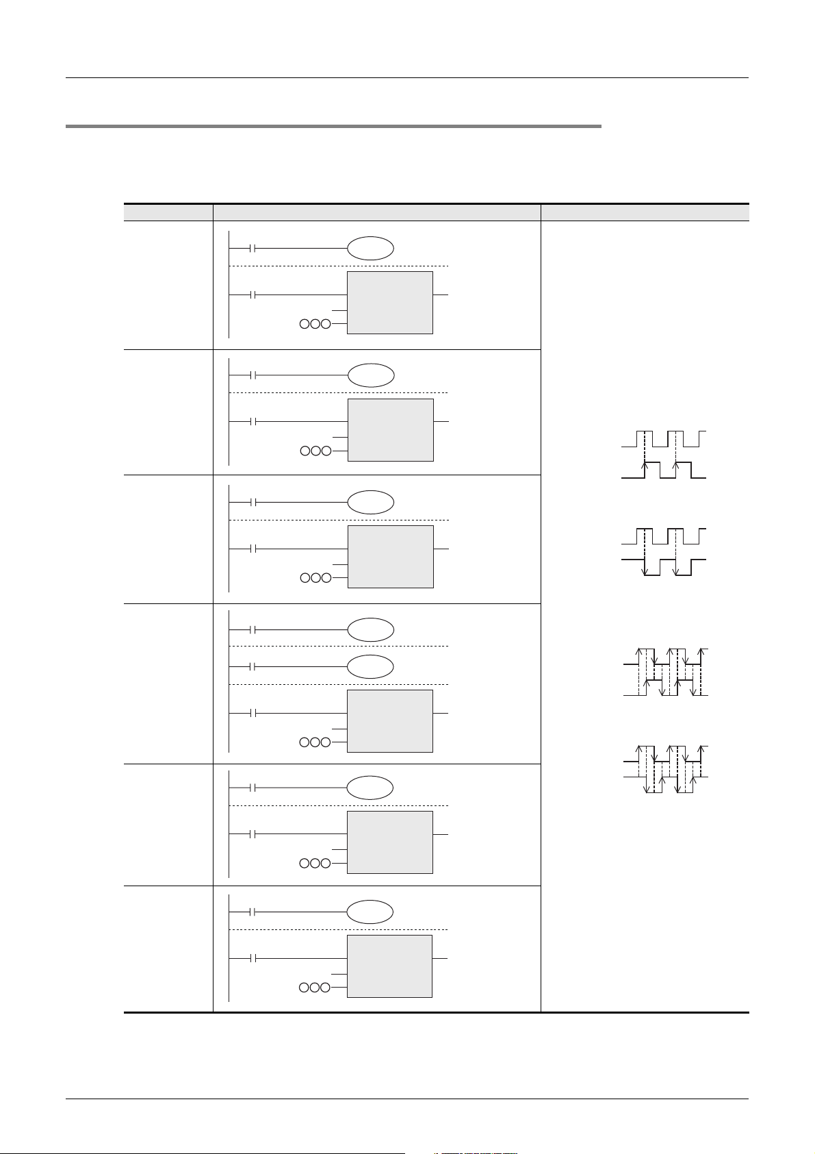
FXCPU Structured Programming Manual
[Device & Common]
2 Devices in Detail
2.7 High Speed Counter [C]
2.7.8 How to use 2-phase 2-counting input counters C251 to C255 for 4-edge counting
2-phase 2-counting input counters C251 to C255 usually executes 1-edge counting, but can be used for 4edge counting by the programs shown in the table below.
FX
0S/FX0/FX0N/FX1S/FX1N/FX1NC/FXU/FX2C/FX2N/FX2NC/FX3S/FX3G/FX3GC PLCs do not support this
function.
Counter No. When using 2-phase 2-counting input counter for 4-edge counting Description
M8000
M8198
C251
C252
C253
C253(OP)
C254
M8000
M8000
M8000
M8388
M8000
CC251
K
CC252
K
CC253
K
CC253
K
CC254
K
OUT_C_32
EN ENO
CCoil
CValue
M8198
OUT_C_32
EN ENO
CCoil
CValue
M8199
OUT_C_32
EN ENO
CCoil
CValue
M8199
M8392
OUT_C_32
EN ENO
CCoil
CValue
M8198
OUT_C_32
EN ENO
CCoil
CValue
1-edge counting (before change)
Phase A
+1
+1
Phase B
Up-counting
Phase A
-1
-1
Phase B
Down-counting
4-edge counting (after change)
+1 +1 +1 +1 +1
Phase A
Phase B
+1 +1 +1 +1
Up-counting
-1 -1 -1 -1 -1
Phase A
Phase B
-1 -1 -1 -1
Down-counting
82
C255
M8000
CC255
K
M8199
OUT_C_32
EN ENO
CCoil
CValue
Page 85
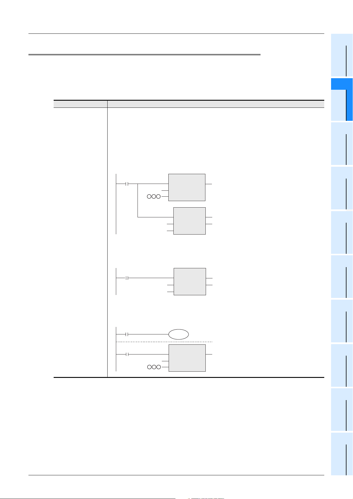
FXCPU Structured Programming Manual
[Device & Common]
2 Devices in Detail
2.7 High Speed Counter [C]
2.7.9 Condition under which hardware counters are handled as software counters
High speed counters are classified into hardware counters and software counters. Under some conditions,
however, hardware counters are handled as software counters.
In this case, use such counters within the range of maximum response frequency and total frequency
determined for software counters.
Conditions under which hardware counters are handled as software counters
Counter No. Conditions under which hardware counters are handled as software counters
Because hardware counters execute counting at the hardware level of the PLC, they can execute counting
without regard to the total frequency.
However, they are handled as software counters in the following conditions.In this case, the maximum
response frequency and total frequency are restricted in the same way as other software counters.
Use M8380 to M8387 to know whether high speed counters are handled as hardware counters or software
counters (only in FX3U/FX3UC PLCs).
• When the DHSCS, DHSCR, DHSZ or DHSCT instruction is used for a hardware counter number, the
corresponding hardware counter is handled as a software counter.
(FX2N/FX2NC PLCs do not support the DHSCT instruction.)
Example: C235
OUT_C_32
EN ENO
K100
K100
CCoil
CValue
EN
s1
s2
EN
s1
s2
DHSCS
DHSCS
ENO
ENO
d
Y000
d
Y000
3U/FX3UC PLCs).
FX3U/FX3UC PLCs
C235
C236
C237
C238
C239
C240
C244(OP)
C245(OP)
C246
C248(OP)
C251
C253
FX2N/FX2NC PLCs
C235
C236
C246
C251
CC235
K
CN235
In this case, C235 is handled as a software counter.
• When an index register is used for a counter number specified in the DHSCS, DHSCR, DHSZ or DHSCT
instruction, all hardware counters are handled as software counters (only in FX3U/FX3UC PLCs).
Example: C235Z0
CN235Z0
• C253 (hardware counter) is handled as a software counter when the logic is reversed using the external
reset input signal logic change function (only in FX
Example: When the logic of the external reset input signal is reversed for C253
→ For reverse of the logic of the external reset input signal, refer to Subsection 2.7.6.
1
Device Outline
2
Devices in
Detail
3
Specified the
Device &
Constant
4
Special Device
5
Errors
6
Types and
Setting of
Parameters
7
Other Functions
M8388
CC253
K
M8389
OUT_C_32
EN ENO
CCoil
CValue
83
Page 86
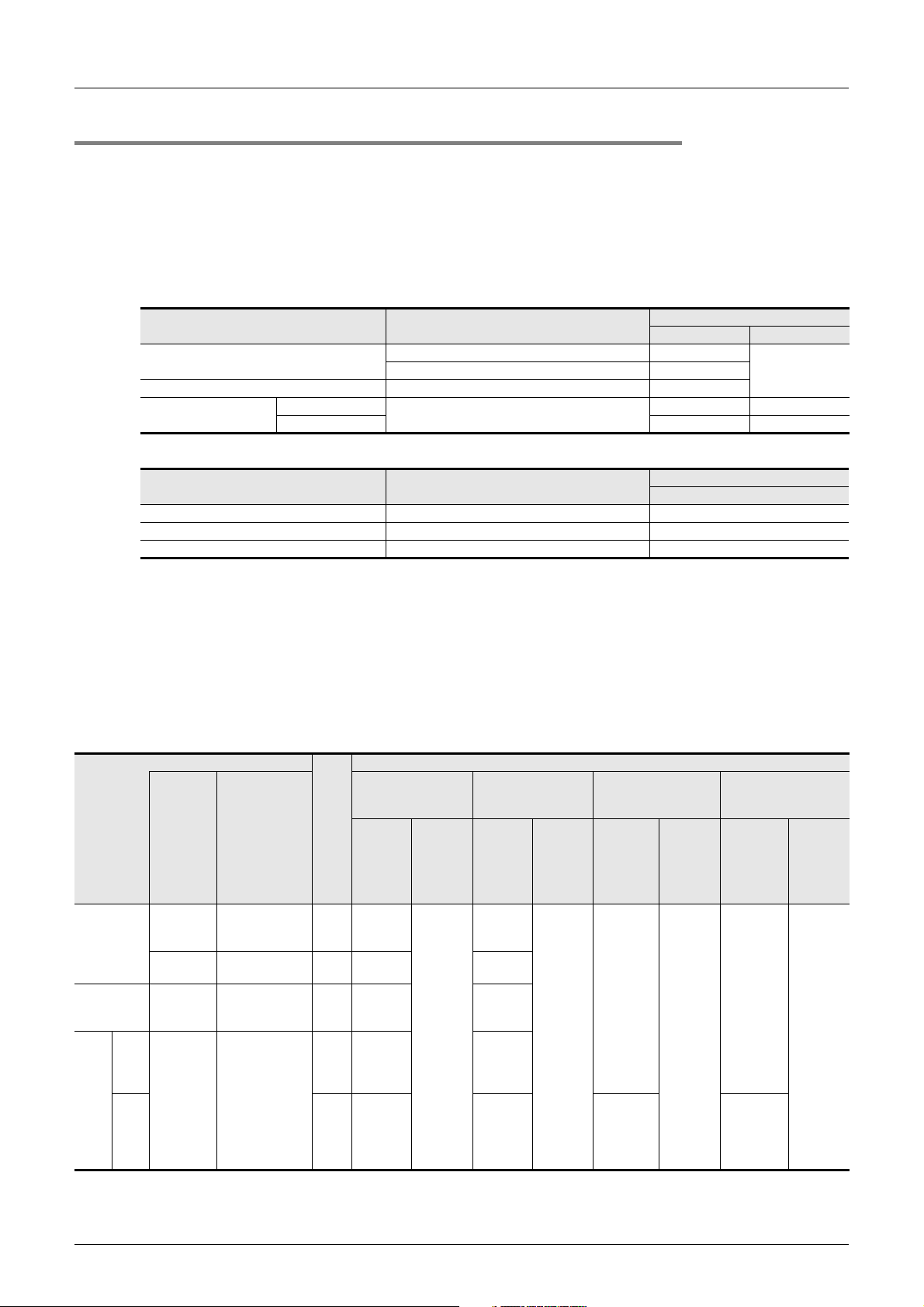
FXCPU Structured Programming Manual
[Device & Common]
2.7.10 Response frequency of high speed counters
1. Response frequency of hardware counters
The tables below show the maximum response frequency of hardware counters.
When hardware counters are handled as software counters in some operating conditions, their maximum
response frequency becomes equivalent to that of software counters, and they are subject to restriction of the
total frequency.
→ For conditions under which hardware counters are handled as software counters, refer to the
1) In FX
2-phase 2-counting input
3U/FX3UC PLCs
Counter No.
1-phase 1-counting input
1-phase 2-counting input C246, C248(OP) 100kHz
1-edge counting
4-edge counting 50kHz 100kHz
C235, C236, C237, C238, C239, C240 100kHz
C251, C253
2 Devices in Detail
2.7 High Speed Counter [C]
previous page.
Maximum response frequency
Main unit FX3U-4HSX-ADP
200kHzC244(OP), C245(OP) 10kHz
50kHz 100kHz
2) In FX
2N/FX2NC PLCs
Counter No.
1-phase 1-counting input C235, C236 60kHz
1-phase 2-counting input C246 60kHz
2-phase 2-counting input C251 30kHz
2. Response frequency and total frequency of software counters
The tables below show the maximum response frequency and total frequency of software counters.
When the DHSZ or DHSCT instruction is used in a program, both the maximum response frequency and the
total frequency are restricted for all software counters without regard to operands of the instruction.
While examining a system or creating a program, consider the restrictions, and use software counters within
the allowable range of maximum response frequency and total frequency.
→ For conditions under which hardware counters are handled as software counters, refer to the
3U/FX3UC PLCs
3U/3UC Series special function blocks/units are not connected
Counter type
Software
counter
-
,
,
,
Following
software
counter
combined with
DHSCS, DHSCR,
DHSZ or DHSCT
instruction
C235, C236
C237, C238
C239, C240
C244(OP)
C245(OP)
C246, C248(OP) ×140 30
C251
,
C253
*1
,
,
,
Maximum
frequency
Magnification for
calculating total frequency
×140
×110 10
×140 30
×410 7.5
Response frequency and total frequency according to instructions used
When DHSZ and
DHSCT instructions
are not used
response
(kHz)
Total
frequency
(kHz)
When only DHSCT
instruction is used
Maximum
response
frequency
(kHz)
30
80
DHSCT instruction, all hardware counters switch to software counters.
1-phase
1-counting
input
1-phase
2-counting
input
2-
count-
phase
2-
count-
ing
input
count-
1) In FX
• When special analog adapters and FX
C241, C242,
C243, C244,
C245
C247, C248,
C249, C250
1-
edge
C252
ing
C253(OP)
C254
4-
C255
edge
ing
*1. When index registers are added to a counter number specified by the DHSCS, DHSCR, DHSZ or
*2. High speed counters C244 (OP) and C245 (OP) can count at up to 10 kHz.
Total
frequency
(kHz)
60
Maximum response frequency
When only DHSZ
instruction is used
Maximum
response
frequency
(kHz)
40 - (Num-
ber of times
of using
instruc-
tions)
(40 - Num-
ber of times
of using
instruc-
tions) / 4
*2
frequency
(kHz)
80 - 1.5 ×
(Number of
times of
instruc-
tions)
Total
using
Main unit
previous page.
When both DHSZ and
DHSCT instructions
are used
Maximum
response
frequency
(kHz)
30 - (Num-
ber of times
of using
instruc-
tions)
(30 - Num-
ber of times
of using
instruc-
tions) / 4
*2
Total
frequency
(kHz)
60 - 1.5 ×
(Number
of times of
using
instruc-
tions)
84
Page 87
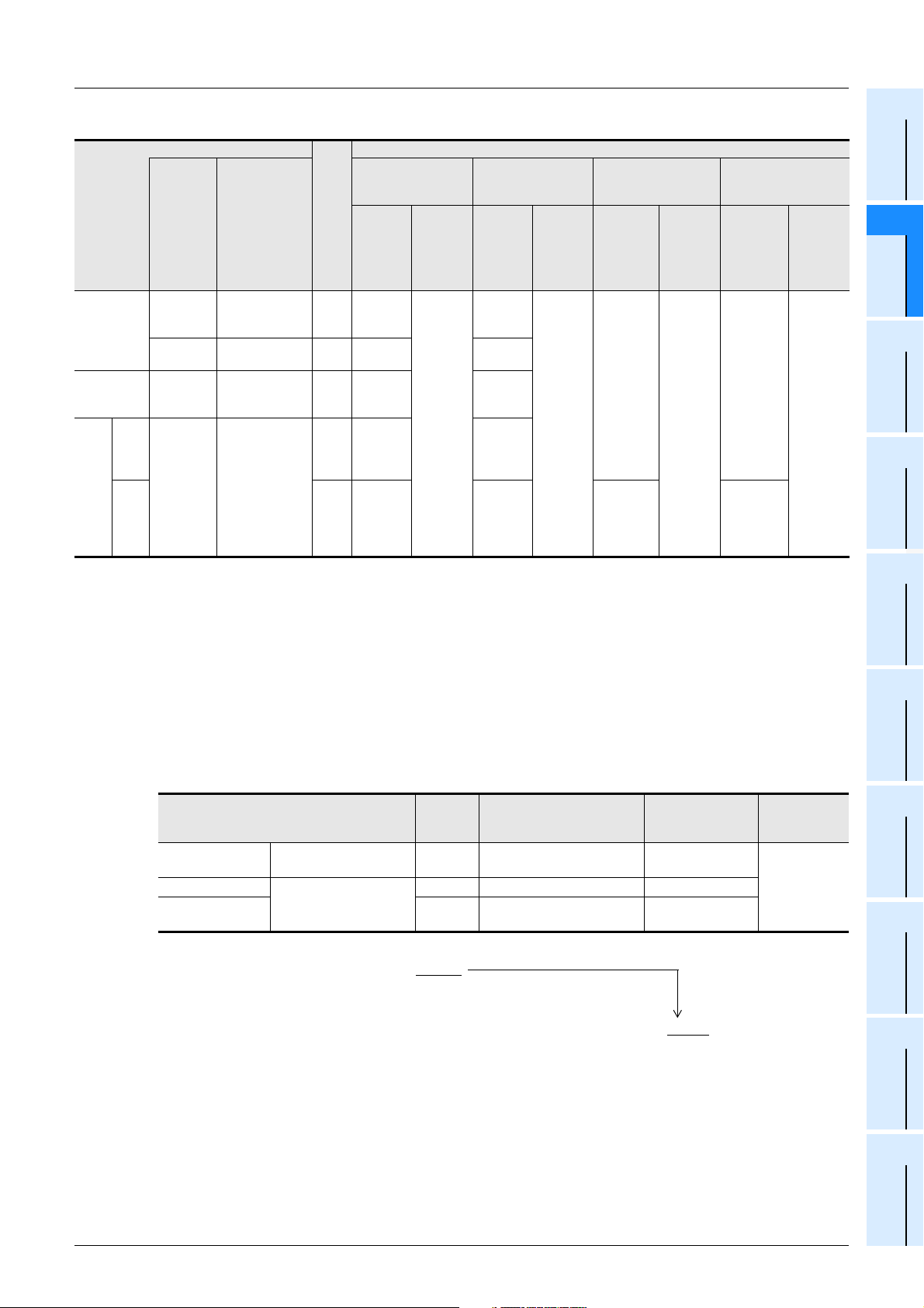
FXCPU Structured Programming Manual
[Device & Common]
• When special analog adapters and FX3U/3UC Series special function blocks/units are connected
Counter type
When DHSZ and
DHSCT instructions
are not used
Maximum
response
frequency
Magnification for
(kHz)
calculating total frequency
×130
×110 10
×130 25
×47.5 6.2
1-phase
1-counting
input
1-phase
2-counting
input
2-
count-
phase
2-
count-
ing
input
count-
Following
software
counter
combined with
DHSCS, DHSCR,
DHSZ or DHSCT
instruction
C235, C236
C237, C238
C239, C240
C244(OP)
C245(OP)
C246, C248(OP) ×130 25
,
C251, C253
*1
,
,
,
1-
edge
ing
4-
edge
ing
Software
counter
C241, C242,
C243, C244,
C245
-
C247, C248,
C249, C250
C252
,
C253(OP)
C254
,
C255
*1. When index registers are added to a counter number specified by the DHSCS, DHSCR, DHSZ or
DHSCT instruction, all hardware counters switch to software counters.
*2. High speed counters C244 (OP) and C245 (OP) can count at up to 10 kHz.
2 Devices in Detail
2.7 High Speed Counter [C]
Response frequency and total frequency according to instructions used
When both DHSZ and
DHSCT instructions
are used
Maximum
response
frequency
(kHz)
25 - (Num-
ber of times
of using
instruc-
*2
tions)
(25 - Num-
ber of times
of using
instruc-
tions) / 4
Total
frequency
(kHz)
60
When only DHSCT
instruction is used
Maximum
response
frequency
(kHz)
25
Total
frequency
(kHz)
50
When only DHSZ
instruction is used
Maximum
response
frequency
(kHz)
30 - (Num-
ber of times
of using
instruc-
tions)
(30 - Num-
ber of times
of using
instruc-
tions) / 4
*2
frequency
(kHz)
50 - 1.5 ×
(Number of
times of
instruc-
tions)
Total
using
Total
frequency
(kHz)
50 - 1.5 ×
(Number
of times of
using
instruc-
tions)
Constant
1
Device Outline
2
Devices in
Detail
3
Specified the
Device &
4
Special Device
5
Errors
• Calculation of the total frequency
Total frequency ≥ Sum of "Response frequency of high speed counter × Magnification for calculating total
frequency"
• Calculation example
When only the DHSZ instruction is used 6 times in a program, the total frequency is calculated as follows in
accordance with the columns for "When only DHSZ instruction is used" shown in the table above.
This calculation example is provided for a system configuration not including special analog adapters and
FX
3U/FX3UC Series special function blocks/units.
Used high speed counter No.
C237
C241
C253(OP)
[4-edge counting]
Operates as software
counter.
Software counter
Input
frequency
30kHz 40 - 6 (times) = 34 kHz ×1
20kHz 40 - 6 (times) = 34 kHz ×1
4kHz {40 - 6 (times)} / 4 = 8.5 kHz ×4
Maximum response
frequency calculation
Magnification for
calculating total
frequency
Used
instruction
DHSZ instruc-
tion × 6 times
1) The total frequency is calculated as follows because the DHSZ instruction is used 6 times:
Total frequency = 80 - 1.5 × 6 = 71 kHz
2) The sum of the response frequency of used high speed counters is
calculated as follows:
{30kHz×1[C237]} + {20kHz×1[C241]} + {4kHz×4[C253(OP)]} =66kHz ≤ 71kHz
6
Types and
Setting of
Parameters
7
Other Functions
85
Page 88
FXCPU Structured Programming Manual
[Device & Common]
2) In FX3G/FX3GC PLCs
Counter type
1-phase
1-counting
input
1-phase
2-counting
input
2-phase
2-counting
input
Software counter
C235, C236, C238
C239, C241
C237, C240, C242
C243, C244, C245
C246, C248(OP) 60kHz
C247, C248, C249
C250
C251, C253(OP) 30kHz
C252, C253, C254
C254(OP), C255
*1. Number of axes used in the following positioning instructions:
PLSY, PLSR , DSZR , DTBL , ZRN , PLSV , DRVI , DRVA
• Calculation of the total frequency
The total frequency is calculated using the following expression:
Response
frequency
,
60kHz
,
10kHz
,
10kHz
,
5kHz
When DHSCS, DHSCR or DHSZ
200 kHz - (Number of positioned axes*1 + Number of
pulse width/period measurement inputs) × 40 kHz
2.7 High Speed Counter [C]
Overall frequency determined by condition of instructions used
instruction is not used
When DHSCS, DHSCR or DHSZ
instruction is used
60 kHz - (Number of positioned axes*1 × 5 kHz)
(Number of pulse width/period measurement
inputs × 20 kHz)
2 Devices in Detail
Total frequency ≥ (Sum of frequency used by 1-phase counters) + (Sum of frequency
used by 2-phase counters)
• Calculation example
Example1: When DHSCS, DHSCR or DHSZ instruction is not used, and instructions related to positioning
(DRVI instruction [Y000] and DRVA instruction [Y001]) are used
Overall frequency: 200 kHz - (2 axes × 40 kHz) = 120 kHz
<Counter No.> <Contents of use>
C235 (1-phase 1-counting) : 50 kHz is input.
C236 (1-phase 1-counting) : 50 kHz is input.
C237 (1-phase 1-counting) : 10 kHz is input.
C253 (2-phase 2-counting) : 5 kHz is input.
Total115 kHz 120 kHz (Overall frequency)
Example2: When DHSCS, DHSCR or DHSZ instruction is not used, and instructions related to positioning
(DRVI instruction [Y000] are used, Number of pulse width/pulse period measurement
inputs(X003)
Overall frequency: 200 kHz - (1 axes + 1 input) × 40 kHz = 120 kHz
<Counter No.> <Contents of use>
C235 (1-phase 1-counting) : 50 kHz is input.
C236 (1-phase 1-counting) : 50 kHz is input.
86
Total100 kHz 120 kHz (Overall frequency)
Page 89
FXCPU Structured Programming Manual
[Device & Common]
3) In FX3S PLC
Counter type
1-phase
1-counting
input
1-phase
2-counting
input
2-phase
2-counting
input
Software counter
C235, C236, C241
C237, C238, C239,
C240, C242, C243,
C244, C245
C246
C247, C248,
C248(OP), C249,
C250
C251
C252, C253,
C253(OP), C254,
C255
*1. Number of axes used in the following positioning instructions:
PLSY, PLSR, DSZR, ZRN, PLSV, DRVI, DRVA
• Calculation of the total frequency
The total frequency is calculated using the following expression:
Response
frequency
60kHz
10kHz
60kHz
10kHz
30kHz
5kHz
When DHSCS, DHSCR or DHSZ
instruction is not used
200 kHz - (Number of positioned axes*1 × 40 kHz) 60 kHz - (Number of positioned axes*1 × 5 kHz)
2 Devices in Detail
2.7 High Speed Counter [C]
Overall frequency determined by condition of instructions used
When DHSCS, DHSCR or DHSZ
instruction is used
Constant
1
Device Outline
2
Devices in
Detail
3
Specified the
Device &
4
Special Device
Total frequency ≥ (Sum of frequency used by 1-phase counters) + (Sum of frequency
used by 2-phase counters)
• Calculation example
Example: When DHSCS, DHSCR or DHSZ instruction is not used, and instructions related to positioning
(DRVI instruction [Y000] and DRVA instruction [Y001]) are used
Overall frequency: 200 kHz - (2 axes × 40 kHz) = 120 kHz
<Counter No.> <Contents of use>
C235 (1-phase 1-counting) : 50 kHz is input.
C236 (1-phase 1-counting) : 50 kHz is input.
C237 (1-phase 1-counting) : 10 kHz is input.
C253 (2-phase 2-counting) : 5 kHz is input.
Total 115 kHz 120 kHz (Overall frequency)
5
Errors
6
Types and
Setting of
Parameters
7
Other Functions
87
Page 90
FXCPU Structured Programming Manual
[Device & Common]
4) In FX1S/FX1N/FX1NC PLCs
2 Devices in Detail
2.7 High Speed Counter [C]
Counter type
1-phase
1-counting
input
1-phase
2-counting
input
2-phase
2-counting
input
Response frequency and total frequency according to instructions used
When DHSCS and DHSCR instructions are not used When DHSCS and DHSCR instructions are used
Software
counter
C235 to C245 ×1
C246 to C250 ×1
C251 to C255 ×2
Maximum response frequency (kHz)
Magnification for
calculating total frequency
C235, C236, C246(1-phase)
C251(2-phase) :30
C237 to C245, C247 to C250(1-phase) :10
C252 to 255(2-phase) :5
*1
Total
frequency
(kHz)
60
Maximum response frequency (kHz)
C235, C236, C246(1-phase)
C251(2-phase) :30
C237 to C245, C247 to C250(1-phase) :10
C252 to 255(2-phase) :5
*1
*1. The maximum response frequency is 60 kHz.
When using two or more high speed counters or when combining a high speed counter and the SPD,
PLSY or PLSR instruction, make sure that the sum of the processing frequency does not exceed the total
frequency shown above.
Calculation example (When the DHSCS and DHSCR instructions are not used)
Total
frequency
(kHz)
30
Used high speed counter No.
C235(1-phase) Software counter 30kHz ×130kHz
C237(1-phase) Software counter 10kHz ×110kHz
C253(2-phase) Software counter 5kHz ×210kHz
Input/output
frequency
Magnification for calculating
total frequency
Calculated value
Total frequency = 60 kHz
Sum of processing frequency = 30 kHz + 10 kHz + 10 kHz = 50 kHz
Sum of processing frequency (50 kHz) ≤ Total frequency (60 kHz)
88
Page 91
FXCPU Structured Programming Manual
[Device & Common]
5) In FX2N/FX2NC PLCs
2 Devices in Detail
2.7 High Speed Counter [C]
1
Device Outline
1-phase
1-counting
input
1-phase
2-counting
input
2-phase
2-counting
input
Counter type
Following
Software
counter
C237 to C245 C235, C236 ×110
C247 to C250 C246 ×110 10 5.5
C252 to C255 C251 ×25
software counter
combined with
DHSCS, DHSCR
or DHSCZ
instruction
Magnification
for calculating
total frequency
Response frequency and total frequency according to instructions used
When DHSCS, DHSCR
and DHSCZ
instructions are not
used
Maximum
response
frequency
(kHz)
Total
frequency
(kHz)
20
When only DHSCS and
DHSCR instructions are
frequency (kHz)
C252 to C255:4
Maximum
response
10
C251:5
used
Total
frequency
(kHz)
11
When only DHSCZ
instruction is used
Maximum
response
frequency
(kHz)
5.5
4
frequency
Total
(kHz)
5.5
When using two or more high speed counters or when combining a high speed counter and the SPD,
PLSY or PLSR instruction, make sure that the sum of the processing frequency does not exceed the total
frequency shown above.
Calculation example (When the DHSCS, DHSCR and DHSZ instructions are not used)
Used high speed counter No.
C235(1-phase)
C237(1-phase) Software counter 3kHz ×13kHz
C253(2-phase) Software counter 2kHz ×24kHz
PLSY(Y0)
PLSY(Y1) 4kHz - 4kHz
Handled as hardware
counter
Pulse output instruction
Input/output
frequency
60kHz
7kHz - 7kHz
Magnification for calculating
total frequency
(Not required to be added
because C235 is handled as
hardware counter)
Calculated value
(Not required to be added
because C235 is handled as
hardware counter)
Constant
Parameters
2
Devices in
Detail
3
Specified the
Device &
4
Special Device
5
Errors
6
Types and
Setting of
Total frequency = 20 kHz
Sum of processing frequency = 3 kHz + 4 kHz + 7 kHz + 4 kHz = 18 kHz
Sum of processing frequency (18 kHz) ≤ Total frequency (20 kHz)
7
Other Functions
89
Page 92
FXCPU Structured Programming Manual
[Device & Common]
6) In FXU/FX2C PLCs
The maximum response frequency of high speed counters C235 to C255 is generally as follows (when
the DHSCS and DHSCR instructions are not used or not driven):
Sum of frequency of 1-phase counters + (Sum of frequency of 2-phase counters) × 4 ≤ 20 kHz
maximum
However, the actual maximum response frequency varies depending on used counters and DHSCS,
DHSCR and DHSZ instructions.
The table below shows the maximum response frequency of each counter. Do not exceed the values
shown below.
(Each value indicates the maximum response frequency of one high speed counter.)
2 Devices in Detail
2.7 High Speed Counter [C]
Combination of
high speed
counters
Counter No. when up to three 1-phase counters are
When only 1phase counters
are used
When one 2phase counter (1
kHz or less) and
one to four 1phase counters
are used
When only 2phase counters
are used
Number of 1-
phase counters
driven
simultaneously
1 - 10 7.0 7.0 5.0 5.0 4.0
2 - 10[A] 3.5 4.0[B] 2.5 2.5 1.5
3 - 6.62.52.52.02.51.5
4- 2.5 1.5 1.5
5- 2.5 1.5 1.5
6- 2.5 1.5 1.0
11 5.0 4.0 3.0
21 4.0 2.0 1.0
31 3.0 2.0 1.0
41 2.0 1.0 1.0
-1 2.0 2.0 2.0
-2 2.0 1.5 1.3
Number of 2-
phase counters
simultaneously
driven simultaneously→
driven
When DHSCS, DHSCR and
DHSZ instructions are not
used or not driven
Maximum response frequency of 1-phase counters
C235, C237,
C238
C236, C239,
C240
Maximum response frequency of 2-phase counters (kHz)
DHSCS, DHSCR
C235, C237,
C238
C236, C239,
C240
When one or two DHSZ
instructions are driven
C235, C237,
C238
C236, C239,
C240
1) The maximum response frequency of counters changes when the DHSCS, DHSCR and DHSZ
instructions are used.
For example, the maximum response frequency of C235 and C237 driven at the same time is 10
kHz (part A), but decreases to 4 kHz (part B) respectively when the DHSCS and DHSCR
instructions are driven at the same time.
2) When the DHSCS, DHSCR and DHSZ instructions are driven at the same time, the maximum
response frequency is equivalent to the maximum response frequency when the DHSZ instruction
is driven.
90
Page 93
FXCPU Structured Programming Manual
[Device & Common]
7) In FX0/FX0N PLCs
2 Devices in Detail
2.7 High Speed Counter [C]
1
Device Outline
Counter type
1-phase
1-counting
input
1-phase
2-counting
input
2-phase
2-counting
input
Software
counter
C235 to C238,
C241 to C242,
C244
C246 to C247,
C249
C251 to C252,
C254
Magnification for
calculating total
frequency
×15
×15
×12
Maximum
response
frequency (kHz)
Total frequency
(kHz)
5
It is not allowed to use 1-phase counters and 2-phase counters together.
Calculation example
Used high speed counter No.
C235(1-phase) Software counter 1kHz ×11kHz
C236(1-phase) Software counter 3kHz ×13kHz
Input/output
frequency
Magnification for calculating
Total frequency = 5 kHz
Sum of processing frequency = 1 kHz + 3 kHz = 4 kHz
Sum of processing frequency (4 kHz) ≤ Total frequency (5 kHz)
8) In FX
0S PLCs
total frequency
Calculated value
Constant
2
Devices in
Detail
3
Specified the
Device &
4
Special Device
5
Errors
Counter type
1-phase
1-counting
input
1-phase
2-counting
input
2-phase
2-counting
input
Magnification for
Software
counter
C235 to C238,
C241 to C242,
C244
C246 to C247,
C249
C251 to C252,
C254
C237(1-phase) Software counter 3kHz ×13kHz
C238(1-phase) Software counter 3kHz ×13kHz
C251(2-phase) Software counter 2kHz ×14kHz
calculating total
frequency
×17
×17
×12
Used high speed counter No.
Maximum
response
frequency (kHz)
Total frequency
(kHz)
14
Input/output
frequency
Magnification for calculating
total frequency
Parameters
Calculated value
Total frequency = 14 kHz
Sum of processing frequency = 3 kHz + 3 kHz + 4 kHz = 10 kHz
Sum of processing frequency (10 kHz) ≤ Total frequency (14 kHz)
6
Types and
Setting of
7
Other Functions
91
Page 94
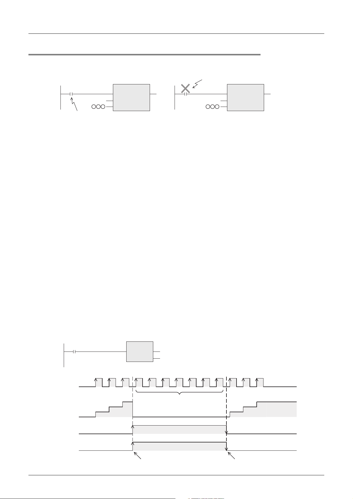
FXCPU Structured Programming Manual
[Device & Common]
2.7.11 Cautions on use
• For a contact to drive the coil of a high speed counter, use a contact which is normally ON during high
speed counting.
Example : M8000(RUN monitor)
OUT_C_32
EN ENO
CC235
K
Program a contact which is
normally ON during counting.
• If the operation of a high speed counter is triggered by a device equipped with a contact such as simulation
switch, the counter may malfunction due to noise generated by chattering of the switch.
• The input filter of input terminals in the PLC main unit used for high speed counters are automatically set
as follows:
3U/FX3UC PLCs: 5 µs (X000 to X005) or 50 µs (X006 and X007)
FX
3G/FX3GC PLCs: 10 µs (X000, X001, X003 and X004) or 50 µs (X002 and X005 to X007)
FX
3S PLC: 10 µs (X000 and X001) or 50 µs (X002 to X007)
FX
1S/FX1N/FX1NC/FX2N/FX2NC PLCs: 20 µs (X000 and X001) or 50 µs (X002 to X005)
FX
0S/FX0/FX0N/FXU/FX2C PLCs: 50 µs (X000 to X003 or X005)
FX
Accordingly, it is not necessary to use the REFF instruction or special data register D8020 (input filter
adjustment).
The input filter of input relays not used for high speed counters remain 10 ms (initial value).
• Inputs X000 to X007 (X003) are used for high speed counters, input interrupt, pulse catch, SPD/DSZR/
DVIT/ZRN instructions and general-purpose inputs.
Make sure to use each input terminal only once.
For example, when C251 is used, X000 and X001 are occupied. As a result, "C235, C236, C241, C244,
C246, C247, C249, C252 and C254", "input interrupt pointers I00* and I10*", "pulse catch contacts M8170
and M8171" and "SPD instruction using X000 and/or X001" cannot be used.
• When a counting input pulse is not provided, none of high speed counter output contacts does not turn ON
even if the PLC executes an instruction in the status "Current value = Set value".
• Counting can be started or stopped in a high speed counter when the output coil (OUT C**) is set to ON or
OFF. Program this output coil in the main routine.
If the output coil is programmed in a step ladder circuit, subroutine or interrupt routine, counting cannot be
started or stopped until the step ladder or routine is executed.
Make sure that the signal input to a high speed counter does not exceed the response frequency described
•
above.
If an input signal exceeds the response frequency, a WDT error or parallel link (communication)
malfunction may occur.
• The response frequency changes depending on number of used counters, but the input filter value is fixed.
Note that noise above the response frequency may be counted depending on the filter value of the used input.
• When a high speed counter is reset by the RST instruction, it cannot execute counting until driving of the
RST instruction is set to OFF.
1) Program example
X010
CCoil
CValue
RST
EN ENO
2 Devices in Detail
2.7 High Speed Counter [C]
Input number corresponding to C235
X000
CC235
K
d
CC235
OUT_C_32
EN ENO
CCoil
CValue
92
2) Timing chart
X000
Current value
of C235
X010
RST
C235
The current value does not change even
3
2
1
if pulses are input because the C235
reset instruction is valid.
C235 remains reset.
Driving of "RST C235" is set to ON
because the contact turns ON.
1
Driving of "RST C235" is set to OFF
because the contact turns OFF.
3
2
Page 95
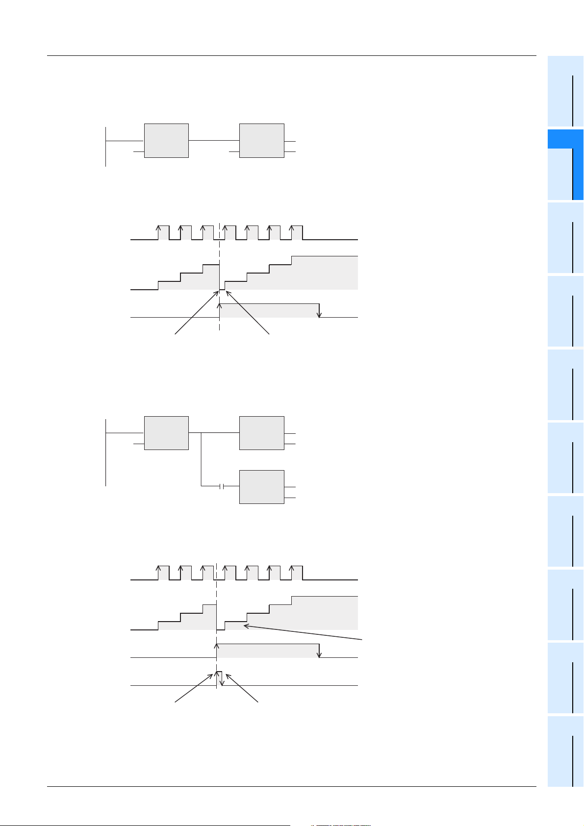
FXCPU Structured Programming Manual
[Device & Common]
• Write the following program "to reset only the current value of a high speed counter (and not to turn OFF
the contact)".
1) Program example
*1
LDP
EN ENO
X010
ssd
*1. When the driving contact is the continuous execution type, the current value of the counter is reset to
"0" at each scan while X010 remains ON.
2) Timing chart
X000
EN ENO
K0 CN235
The current value of C235 is cleared (to "0").
DMOV
2 Devices in Detail
2.7 High Speed Counter [C]
Constant
1
Device Outline
2
Devices in
Detail
3
Specified the
Device &
4
3
Current value
of C235
X010
Because X010 turns ON,
"FNC12 DMOV" is executed.
The current value of C235
is reset to "0".
1
3
2
2
1
Because the driving contact is the pulse execution type,
C235 executes counting normally after that.
• Write the following program "to turn OFF the contact and reset the current value of a high speed counter".
1) Program example
*1
X010
LDP
EN ENO
sd
M8001
RUN monitor
(Normally OFF)
RST
EN ENO
RST
EN ENO
- - - - - A)
CN235
d
- - - - - B)
CN235
*1. When the driving contact is the continuous execution type, the current value of the counter is reset to
"0" and the counter reset status is cleared at each scan while X010 remains ON.
2) Timing chart
4
Special Device
5
Errors
6
Types and
Setting of
Parameters
7
Other Functions
X000
4
3
Because the reset status is
cleared, C235 executes counting.
Current value
of C235
X010
RST
C235
Counter is reset (part A)
in above program).
1
3
2
2
1
Driving of counter reset is set to OFF
(part B) in above program).
• For writing the symbolic information and changing the set values of timers and counters using a peripheral
equipment, it is recommended to create programs with the set values specified indirectly.
If the set values are specified directly, programs cannot be restored from the symbolic information after the
set values are changed.
93
Page 96
FXCPU Structured Programming Manual
[Device & Common]
2.8 Data Register and File Register [D]
Data registers store numeric values. File registers are handled as initial values of data registers.
FX
0S and FX0 are not applicable to file registers.
Each data register or file register stores 16-bit data (whose most significant bit specifies the positive or
negative sign). Two data registers or file registers combined can store 32-bit data (whose most significant bit
specifies the positive or negative sign).
→ For the functions and operations of file registers, refer to Subsection 2.8.4.
2.8.1 Numbers of data registers and file registers
The tables below show data register and file register [D] numbers. (Numbers are assigned in decimal.)
1. In FX3S/FX3G/FX3GC/FX3U/FX3UC PLCs
Data registers
Fixed latched
(battery backed-up)
type
D512 to D7999
7488 points
*3*4
FX3U/FX3UC
PLCs
General type
D0 to D199
200 points
*1
Latched (battery
backed-up) type
D200 to D511
312 points
*2
Special type
D8000 to D8511
512 points
*3
2 Devices in Detail
2.8 Data Register and File Register [D]
File registers (latched (battery
backed-up) type)
D1000*4 and later
7000 points maximum
Data registers
File registers (latched (EEPROM
backed-up) type)
D1000*4 and later
7000 points maximum
File registers (latched (EEPROM
backed-up) type)
D1000*4 and later
2000 points maximum
FX3G/FX3GC
PLCs
FX3S PLC
General type
D0 to D127
128 points
General type
D0 to D127
128 points
*3
Fixed latched
(EEPROM backed-
up) type
D128 to D1099
972 points
Fixed latched
(EEPROM backed-
up) type)
D128 to D255
128 points
*3
Data registers
General type Special type
D1100 to D7999
6900 points
General type Special type
D256 to D2999
2744 points
*5
D8000 to D8511
512 points
D8000 to D8511
512 points
*3
*1. This area is not latched, but can be changed to the latched (backed-up) area by parameter setting.
*2. This area is latched, but can be changed to the non-latched (non-backed-up) area by parameter
setting.
*3. The characteristics about latch (battery backup) cannot be changed using parameters.
*4. Data registers D1000 and later can be used as file registers in units of 500 points by parameter
setting.
*5. This area can be changed to the latched (battery backed-up) area by parameter setting while an
optional battery is attached, but the latched (battery backed-up) range cannot be specified.
When simple N:N link or parallel link is used, some data registers are occupied for the link.
→ Refer to the data communication manual.
94
Page 97
FXCPU Structured Programming Manual
[Device & Common]
2. In FX1S/FX1N/FX1NC/FX2N/FX2NC PLCs
Latched
General type
FX1S PLCs
FX1N/FX1NC
PLCs
FX2N/FX2NC
PLCs
D0 to D127
128 points
D0 to D127
128 points
D0 to D199
200 points
*1. This area is not latched, but can be changed to the latched (backed-up) area by parameter setting.
*2. This area is latched, but can be changed to the non-latched (non-backed-up) area by parameter
setting.
*3. The characteristics about latch (backup) cannot be changed using parameters.
*4. Data registers D1000 and later can be used as file registers in units of 500 points by parameter
setting.
When simple N:N link or parallel link is used, some data registers are occupied for the link.
(battery
backed-up)
*3
*3
D200 to D511
*1
312 points
type
--
--
D512 to D7999
*2
7488 points
Data registers
Fixed latched (battery backed-up) type
Battery
backed-up
EEPROM
backed-up
D128 to D255
128 points
D128 to D255
128 points
*3
Capacitor
backed-up
*3
D256 to D7999
*3
7744 points
--
→ Refer to the data communication manual.
2 Devices in Detail
2.8 Data Register and File Register [D]
1
Device Outline
File registers
Special type
-
D8000 to D8255
256 points
D8000 to D8255
*3
256 points
D8000 to D8255
256 points
(latched (battery
backed-up) type)
D1000*4 and later
1500 points maximum
D1000*4 and later
7000 points maximum
D1000*4 and later
7000 points maximum
Constant
2
Devices in
Detail
3
Specified the
Device &
4
Special Device
3. FX0S/FX0/FX0N/FXU/FX2C PLCs
Data registers
Fixed latched
(backed-up) type
D30, 31
*3
2 points
D128 to D255
128 points
D512 to D999
488 points
*3
*3
-
Special type
D8000 to D8069
27 points
D8000 to D8129
38 points
D8000 to D8137
85 points
D8000 to D8135
69 points
FX0/FX0S
PLCs
FX0N
PLCs
FXU/FX2C
PLCs
FXU PLCs
(Ver. 2.30 or
earlier)
(Reference)
General type Latched (backed-up) type
D0 to D29
30 points
D0 to D127
128 points
D0 to D199
200 points
*4
*4
*1
Master→Slave:D490 to D499
Slave→Master:D500 to D509
-
-
D200 to D511
312 points
*2
For link
*1. This area is not latched, but can be changed to the latched (backed-up) area by parameter setting.
*2. This area is latched, but can be changed to the non-latched (non-backed-up) area by parameter
setting.
*3. This area is fixed to the latched (backed-up) type (, and the contents can be cleared by the RST and
ZRST instructions).
*4. This area is fixed to the non-latched (non-backed-up) type (, and the characteristics about latch
(backup) cannot be changed).
*5. Data registers D1000 and later can be used as file registers in units of 500 points by parameter
setting.
*6. Data registers D6000 to D7999 can be used as file registers by driving the special auxiliary relay
M8074 and prohibiting sampling trace.
Different from file registers secured inside the program memory, D6000 to D7999 are secured inside
the system memory of the PLC, and may be called "RAM file registers" (to notify that they are the
latched type).
File registers
-
D1000*5 and later
1500 points maximum
D1000*5 and later
2000 points maximum
D6000 to D7999
2000 points(RAM file)
-
5
Errors
6
Types and
Setting of
Parameters
*6
7
Other Functions
95
Page 98
FXCPU Structured Programming Manual
r
r
[Device & Common]
2.8.2 Structure of data registers and file registers
1) 16-bit type
One (16-bit) data register or file register can store a numeric value within the range from -32768 to
+32767.
2 Devices in Detail
2.8 Data Register and File Register [D]
4,096
8,192
2,048
D 0(16-bit type)
64
128
256
512
1,024
32
16
1010101010101010
b0
1
2
4
8
High order Low orde
b15
Sign
0 : Positive
1 : Negative
16,384
A numeric value can be read from or written to a data register by an instruction usually.
Or a numeric value can be directly read from or written to a data register from a display unit, display
module or programming tool.
2) 32-bit type
Two serial data registers or file registers can express 32-bit data.
- A data register having a larger device number handles high-order 16 bits, and a data register having a
smaller device number handles low-order 16 bits.
- In the index type, V handles high-order 16 bits, and Z handles low-order 16 bits.
- Two serial data registers or file registers can store a numeric value within the range from -2,147,483,648
to +2,147,483,647.
High order Low orde
b31 b0
Sign
0 : Positive
1 : Negative
D 1(High-order 16 bits) D 0(Low-order 16 bits)
1010101010101010
1,024
2,048
4,096
8,192
16,384
32,768
65,536
131,072
262,144
524,288
1,048,576
2,097,152
4,194,304
8,388,608
16,777,216
33,554,432
67,108,864
134,217,728
268,435,456
536,870,912
1,073,741,824
512
256
128
64
32
16
0000111100001111
1
2
4
8
In the case of 32-bit type, when a data register or file register on the low-order side (Example: D0) is
specified, the subsequent number on the high-order side (Example: D1) is automatically occupied.
Either an odd or even device number can be specified for the low-order side, but it is recommended to
specify an even device number for the low-order side under consideration of the monitoring function of
display units, display modules and programming tools.
2.8.3 Functions and operation examples of data registers
Data registers store numeric data.
Each data register stores 16-bit data (whose most significant bit specifies the positive or negative sign). Two
data registers combined can store 32-bit data (whose most significant bit specifies the positive or negative
sign).
1. General type and latched (backed-up) type data registers
• Once data is written to a data register, it does not change unless other data overwrites it.
When the PLC mode switches from "RUN" to "STOP" or when the power is interrupted, however, all data
stored in general type data registers are cleared to "0".
If the special auxiliary relay M8033 has been driven in advance, data are held even when the PLC mode
switches from "RUN" to "STOP".
• Latched (backed-up) type data registers hold their contents even when the PLC mode switches from
"RUN" to "STOP" or when the power is interrupted.
• The contents of data registers are latched (backed up) by a battery, EEPROM, etc. built in the PLC.
→ For details on each backup method, refer to Section 2.6.
• When using fixed latched (backed-up) type data registers as general type registers, provide the following
reset circuit using the RST or ZRST instruction at the head step in a program.
M8002
Initial pulse
ZRST
EN ENO
d1
d2
Data stored in D512 to D999 are cleared to "0".
D512
D999
→ For file registers, refer to Subsection 2.8.4.
96
Page 99
FXCPU Structured Programming Manual
[Device & Common]
2. Special type data registers
• Special type data registers store specific data in advance, or receive data for special purpose.
The contents of special data registers are set to their initial values when the power is turned ON.
(Generally, these data registers are cleared to "0" first, and then initial values (if there are any) are written
by the system ROM.)
• For example, the watchdog timer time is set initially to D8000 by the system ROM. To change the contents,
write desired time to D8000 using the transfer instruction MOV.
2 Devices in Detail
2.8 Data Register and File Register [D]
1
Device Outline
2
Devices in
Detail
M8002
Initial pulse
K250
MOV
ENsENO
WDT
EN ENO
The watchdog timer is set to 250 ms.
d
D8000
The watchdog timer is refreshed.
→ For the backup characteristics of special data registers, refer to Section 1.2 and Chapter 4.
→ For types and functions of special data registers, refer to Chapter 4.
3. Operation examples
Data registers can be used in various controls handling numeric data.
This paragraph explains representative operation examples among various applications.
For the full use of data registers, refer to the explanation on applied instructions provided later.
1) Specifying the set value of a timer or counter
OUT_T
EN ENO
TCoil
TC2
D0
TValue
OUT_C
EN ENO
D20
CCoil
CValue
CC10
2) Operation examples using the MOV instruction
a) Changing the current value of a counter
MOV
ENsENO
D5 CN2
d
A counter or timer operates while regarding the
contents of a specified data register as its set
value.
The current value of the counter C2 is changed to
the contents of D5.
3
Specified the
Device &
Constant
4
Special Device
5
Errors
6
Types and
Setting of
Parameters
7
Other Functions
b) Reading the current value of a timer or counter
MOV
ENsENO
CN10 D4
d
c) Storing a numeric value in data registers
16-bit type
MOV
ENsENO
K200 D10
d
32-bit type
DMOV
ENsENO
K80000 D10
d
The current value of the counter C10 is transferred
to D4.
"200 (decimal value)" is transferred to D10.
"80000 (decimal value)" is transferred to D10 and
D11.
Because a numeric value larger than "32767" is
32-bit data, a 32-bit operation is required.
When a data register on the low-order side (D10)
is specified, a data register on the high-order side
(D11) is automatically occupied.
97
Page 100
FXCPU Structured Programming Manual
[Device & Common]
d) Transferring the contents of a data register to another data register
MOV
ENsENO
D10 D20
3) Using unoccupied timers and counters as data registers
Operation example using the MOV instruction
Timers and counters not used in a program can be used as devices for storing 16-bit or 32-bit numeric
values (data registers).
MOV
ENsENO
K300
MOV
ENsENO
TN10
With regard to 32-bit data, two 16-bit timers or counters (such as C1 and C0) can express 32-bit data in
the same way as data registers.
Each 32-bit counter (such as C200) can handle 32-bit data individually.
2 Devices in Detail
2.8 Data Register and File Register [D]
The contents of D10 are transferred to D20.
d
"300 (decimal value)" is transferred to T10.
d
TN10
The contents of T10 are transferred to the current
d
CN20
value register of C20.
In this case, T10 is not working as a timer, but is
working as a data register.
98
 Loading...