

Page 1
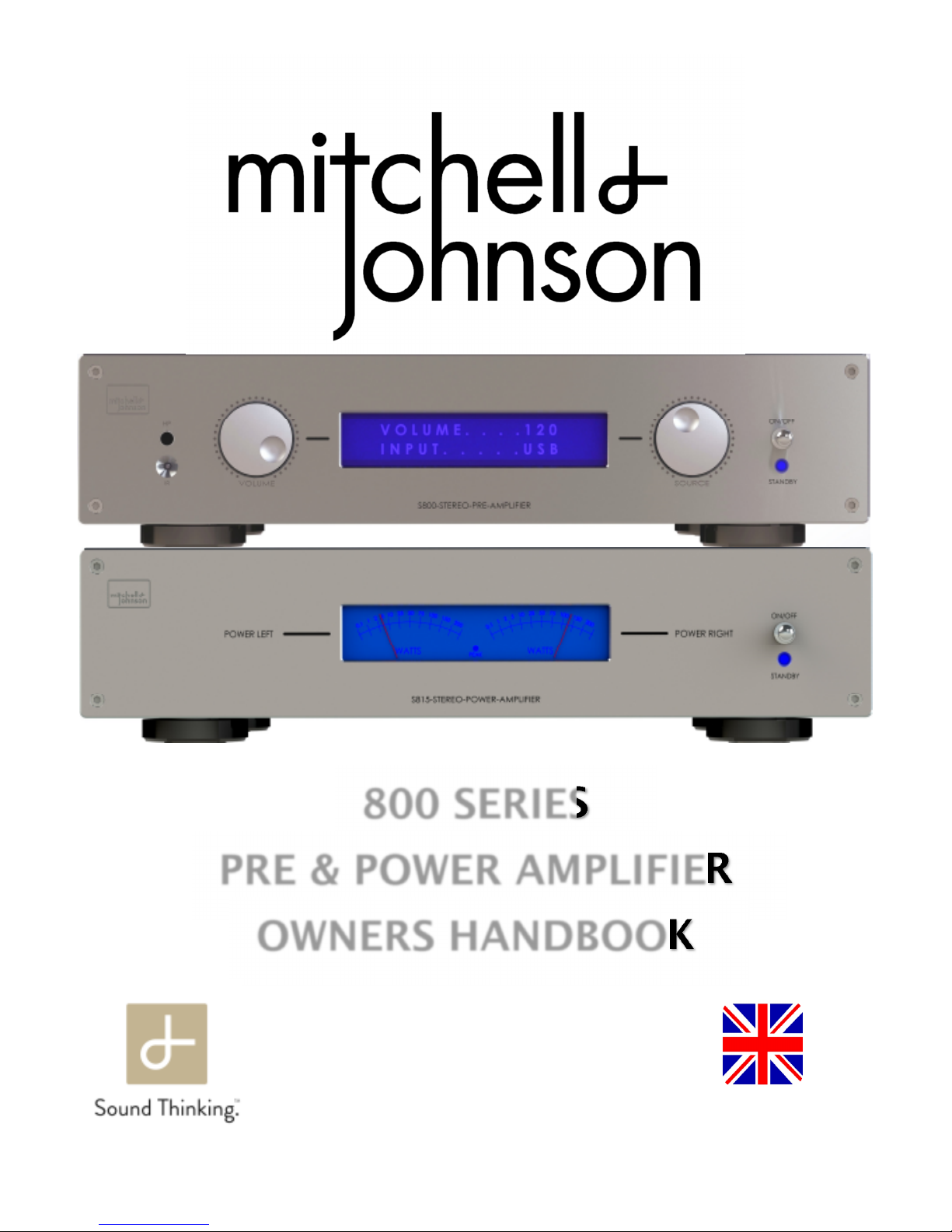
800 SERIES
PRE & POWER AMPLIFIER
OWNERS HANDBOOK
Made in the UK
Made in the UKMade in the UK
Made in the UK
Page 2

2
Index
Index.............................................................................................................................................. 2
Warranty…………………………………………………………………………………………...……… 3
Declaration of Conformity........................................................................................................... 4
Introduction, Environmental, WEEE, Made in the UK............................................................... 5
Installation & Safety Advice........................................................................................................ 6
PRE-AMPLIFIER INSTRUCTIONS…………………………………………………………………….. 7
Rear Panel..................................................................................................................................... 8
Front Panel…………………………………………………………………………………………..…… 9
Overview and Input Connections ………………………………………………………………….... 10
Balanced Connections………………………………………………………...…………………….… 11
Output Connections / Cables ………………………………………………………………………... 12
Front Panel Operation…………………………………………………………………………………. 13
Remote Control…………………………………………………………………………………………. 14
Setup Menu Options.......................................................................................................... 15 to 18
USB Audio…….…………….…………………………………………...……………..……….... 19 to 20
Pre-Amplifier Specifications ...................................................................................................... 21
POWER AMPLIFIER INSTRUCTIONS……………………………………………………….……….. 22
Rear Panel………………………………………………………………………………………..…….… 23
Front Panel……………………………………………………………………………………………….. 24
Overview and Input Connections………………………………………...………………………….. 25
Output Connections……………………………………………………………………………………. 26
Power Amplifier Specifications………………………….…………………………………………… 27
Rear cover and Contact details ……………………………………………………………………….28
Page 3

3
PLEASE RETAIN YOUR ORIGINAL PURCHASE RECEIPT AND
PLACE IT HERE FOR SAFEKEEPING
YOUR WARRANTY PERIOD WILL COMMENCE FROM THE
DATE OF PURCHASE SHOWN ON THE RECEIPT
Warranty
Page 4

4
EC Declaration of Conformity
In accordance with EN ISO 17070-1:2004
We Mitchell & Johnson electronics ltd
of Severn Farm Industrial Estate
Welshpool
Powys
UK in accordance with the following Directive(s): 2006/95/EC The Low Voltage Directive 2004/108/EC The Electromagnetic Compatibility Directive hereby declare that: Equipment: Mitchell & Johnson 800 preamplifier and 815 power amplifier are in conformity with the applicable requirements of the following standards Standard. No. Name International Equivalents BS EN60065; 2002 Electrical Safety Requirements EN60065; 2002 / IEC60065; 2001
BS EN 55020; 2002 EMC Immunity EN55020; 2002 / CISPR 20; 2002
BS EN 55013; 2001 EMC Emissions EN55013; 2001 / CISPR 12; 2001
BS EN 61000-3-2; 2001 EMC Limits for Harmonic Emissions EN61000-3-2; 2000 / IEC61000-3-2; 2000
BS EN 61000-3-3; 1995 EMC Limits for Voltage Fluctuations EN61000-3-3; 1995 / IEC61000-3-3; 1994 I hereby declare that the equipment named above has been designed to comply with the relevant sections of the above referenced specifications.
The unit complies with all applicable Essential Requirements of the Directives and Standards.
Signed by: .................................................................................................................................................
Name: Nia Davies
Position: Managing Director
Done at: Mitchell & Johnson Electronics Ltd.
On: 02/08/2017
17
Page 5

5
Introduction
Congratulations on your purchase of a Mitchell & Johnson 800 series products.
The Mitchell & Johnson range has been painstakingly engineered in the United Kingdom
to offer class leading performance.
Users should read and follow this instruction manual, paying particular attention to the user
installation and safety advice sections.
This manual has been written to enable you to achieve the very best performance and maximum
listening pleasure from your investment.
We wish you many years of pleasurable listening.
With best regards, the Mitchell & Johnson team
Environmental Issues
Although Mitchell & Johnson electronics operate in standby mode as opposed to being fully
switched off, the power drain has been optimised to a negligible level. Contrary to popular audiophile practice, we do not recommend leaving our power amplifiers permanently powered.
All Mitchell & Johnson amplifiers have been designed to attain full operational specifications and
sound quality within a few minutes of switch-on.
Mitchell & Johnson operates a 100% recycling program. All waste materials generated as part of
the manufacturing process at Mitchell & Johnson are recycled via a licensed specialist company.
WEEE Scheme
Disposal of Electronic Equipment in the European Union and other countries with
collection procedures:
The wheelie bin symbol on this product indicates that it shall not be treated as household waste. It
should be disposed of via a collection point for the recycling of electrical and electronic equipment.
Made in the UK
Your Mitchell & Johnson 800 series products were entirely designed and manufactured in the UK.
Page 6

6
VERY IMPORTANT
Before connecting your new Mitchell & Johnson units to the rest of your system, please
ensure all required input/output cables are connected BEFORE inserting the mains power
lead and powering for the first time.
User installation and safety advice
Please ensure that the mains voltage of your new Mitchell & Johnson devices are correct
for your region. The setting is displayed on a label next to the mains power inlet.
The mains voltage setting is not user adjustable, therefore the product must be returned to
the dealer/manufacturer if any changes are required.
Ensure the mains supply is switched off at the wall socket, or unplugged before installing
or moving the units.
Do not use near water, for example do not place a potted plant on top of the units or allow
drinks to be placed near the units. If liquid is spilt in to the cabinet, remove the mains leads
from the wall immediately.
The products should then be returned to your dealer for safety testing before re-use.
Failure to do so may result in electric shock or even fire!
Do not use the units in damp conditions, for example, outside of the house.
In the event of an electrical storm, remove the mains power leads from the wall outlet.
Keep away from direct sunlight and other heat sources and ensure adequate ventilation
around the products to maintain proper cooling.
Units MUST NOT be stacked directly on top of each other.
Never attempt to open the cabinets. There are no user serviceable parts inside and doing
so will invalidate the manufacturers warranty.
Care should be taken to ensure there is no possibility of short circuit behind the units when
in use, for example, metal framed hi-fi units may be a hazard.
Page 7
7
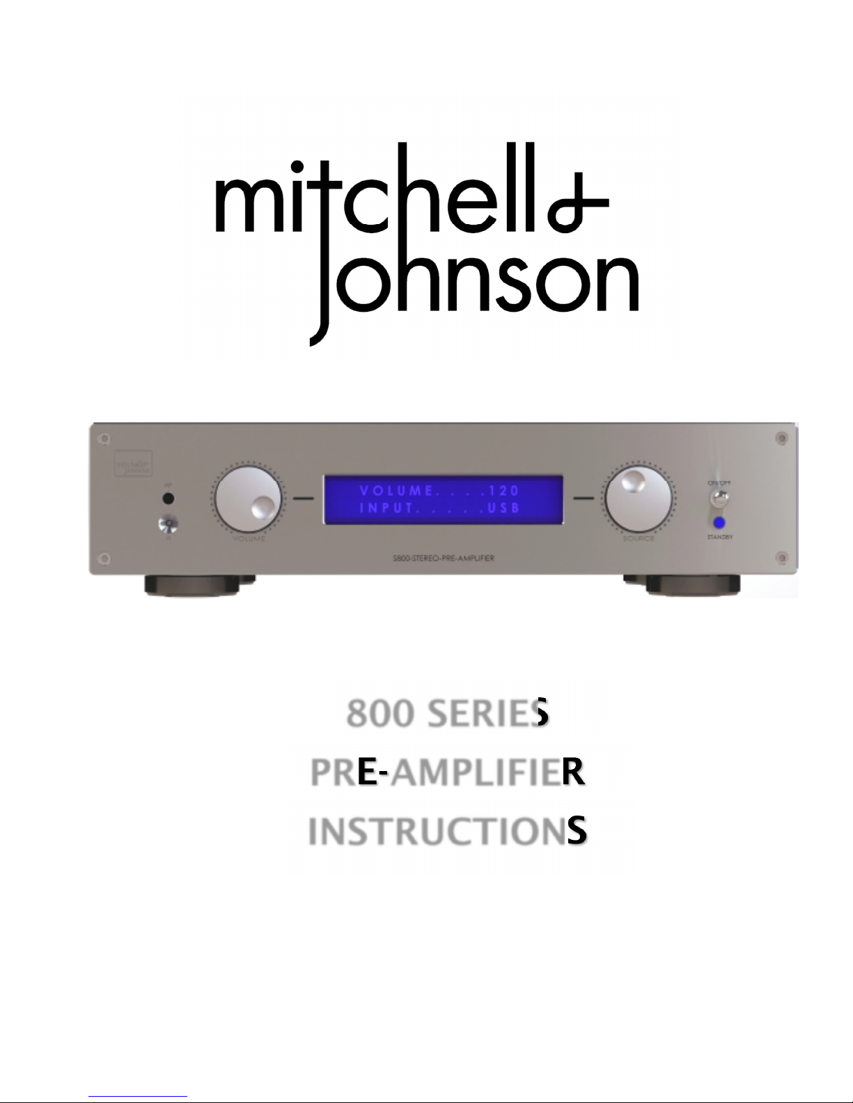
800 SERIES
PRE-AMPLIFIER
INSTRUCTIONS
Page 8
8
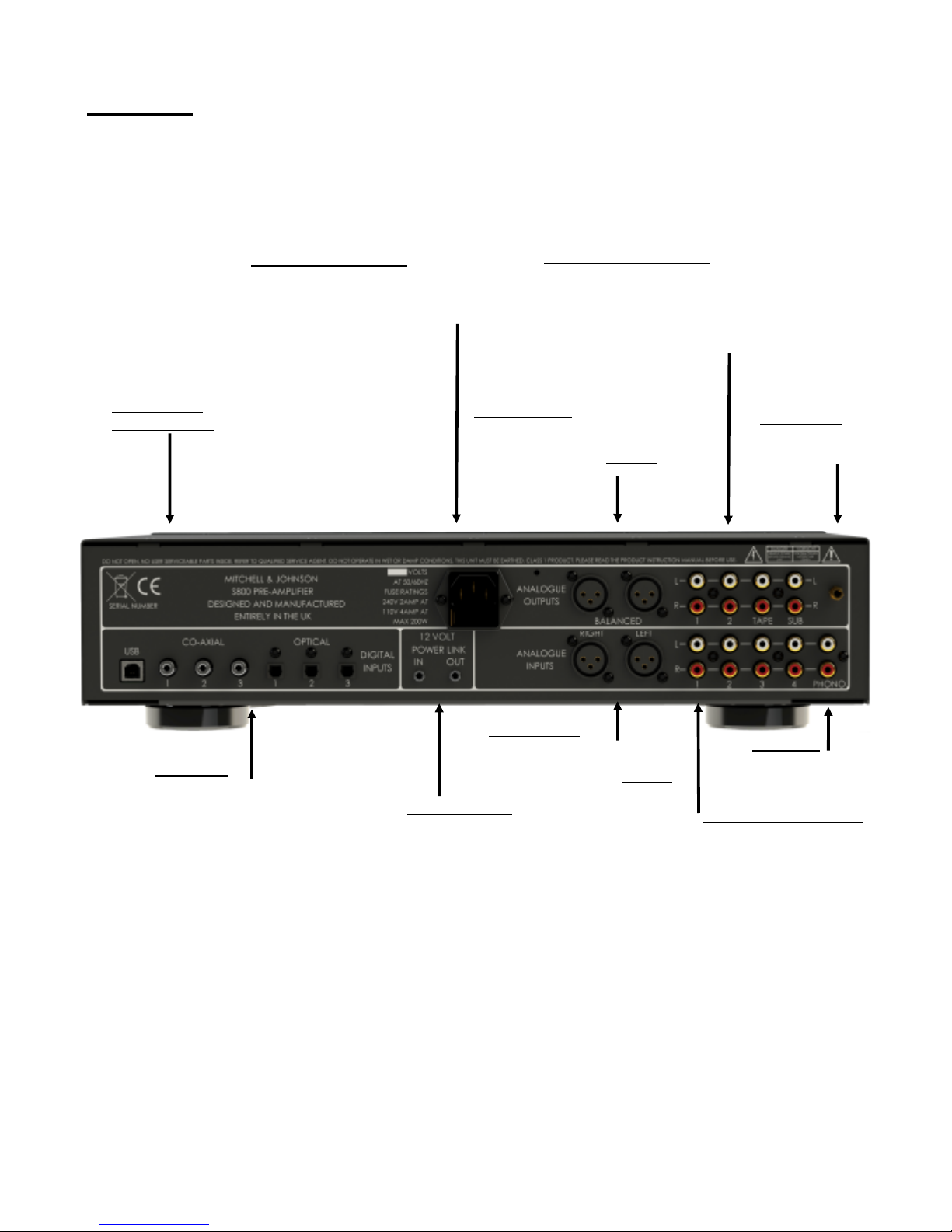
Power Inlet and fuse ratings
Please ensure that the specification indicated adjacent to the connector is correct
for your area.
This will either be 230VAC or 115VAC.
Digital Inputs
USB Asynchronous
3 x Optical
3 X Co-Axial
Pre-Amp unbalanced Outputs
Outputs 1 and 2 are for connecting
an amplifier.
Tape out is not volume controlled for
recording.
Sub out is for supplying a volume
controlled feed to an active
subwoofer system.
Analogue Unbalanced Inputs
Labelled 1 to 4.
The displayed name for each
input can be edited in the setup
menu.
Phono input
Selectable MM/MC
In user setup menu.
Rear Panel
Phono Ground
Connect turntable
Ground here if fitted.
Balanced inputs
Devices such as balanced output
CD players can be connected here.
Connections comply with European
standard pin polarity wiring
Serial Number &
Safety Information
Balanced outputs
For connection to an amplifier with
balanced inputs
Connections comply with European
standard pin polarity wiring
12 volt power links
Used to link units together
for synchronised on/off
Page 9
9
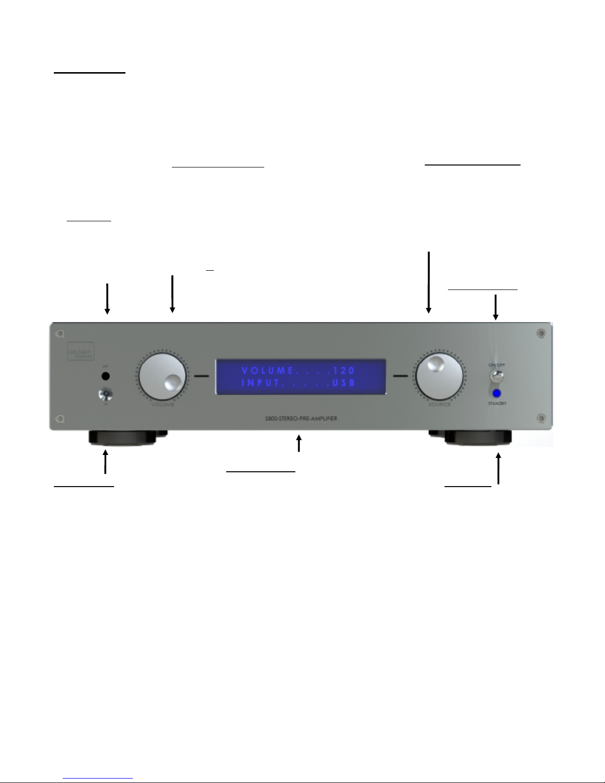
Input selector/Power on/off
Rotating clockwise or anticlockwise will cycle through the list of
available inputs.
Unused inputs can be suspended
from the list and required inputs
can be re-named in the setup
menu. See page 13
Information Display
Volume setting and selected input
displayed by default.
Menu selection information is
displayed when in MENU mode.
Volume Knob/Menu select
Volume knob rotates in the
conventional way to regulate
the amplifiers volume. The
volume level is shown on the
main display.
Pushing the volume knob will
enable the menu page for customising the user settings.
See page 15 for details.
Headphones
6.35mm output socket for
integrated headphone
amplifier.
Headphone impedance
should be a minimum of
32 Ohms.
Front Panel
Infra red receiver
Both the volume knob and the Source knob incorporate a push switch to change functions.
Pushing and holding the volume knob for 5 seconds will toggle in and out of the setup menu.
Pushing the Input knob will change the settings in each setup sub menu.
Standby light
2 way power switch
See page13
Page 10

10
Mitchell & Johnson 800 series pre-amplifier Overview
The Mitchell & Johnson 800 pre-amplifier is a class leading product, capable of superb performance
at the heart of an audiophile stereo system. It incorporates a substantial number of connections for
both analogue and digital sources.
In all there are 13 potential source connections.
Connections
Input Connections
Analogue 1-4 > The Mitchell & Johnson 800 pre-amplifiers analogue inputs should only be con-
nected to the analogue outputs (usually marked left/right and colour coded white/red) from a source
component.
Balanced > High end sources often feature this kind of connection. It does not offer any inherent
advantage over unbalanced connections in short cables but it does offer better signal to noise and
hum rejection in long cables where the components are sited some distance apart.
Phono > This is where a turntable should be connected which dos NOT have an integrated phono
stage pre-amplifier. The Mitchell & Johnson 800 pre-amplifiers phono stage can be used with either
a Moving Magnet or a Moving Coil cartridge. The relevant setting is accessible in the setup menu.
Digital
Optical 1-3 > Optical connections are commonly used on televisions, games machines and satellite
television receivers to transfer digital audio information from one component to another.
The main benefit of optical connections is that there is no direct earth connection between units,
thereby avoiding induced hum from ground loops or switch mode power supply noise being passed
from one device to another.
Co-Axial 1-3 > Many CD players, streaming network players and external processors use Co-Axial
wired connections. Theoretically the quality is superior to optical with less jitter induced in the transmission chain, but in practice it probably makes little difference.
USB > Computer based music playback, if from a conventional computer or a media server (just a
computer hidden in a box) is generally via a USB connection.
The Mitchell & Johnson 800 pre-amplifier has an asynchronous connection using an XMOS USB
interface chip. This does not require a driver with Apple, Linux or Android based systems. However,
Microsoft devices will require a suitable driver and setup for the interface to work. See page 19
Page 11

11
Input Connections continued
Balanced.
The Mitchell & Johnson 800 pre-amplifier incorporates a balanced input connection via XLR.
Balanced connections are the normal method of connecting devices in the professional audio world.
The audio signal is transmitted down the cable using two separate conductors.
One signal is normal plus phase as would be in a standard phono/cinch type cable.
The second signal is identical but reverse (minus) phase.
The inverted signal is re-inverted in the receiving device making it plus phase.
The two signals are then added together to produce the original source signal.
However, any noise or hum induced in the cable is effectively cancelled out.
Other than greater noise rejection, there is no inherent advantage to be gained by using balanced
connectors in a domestic setting, unless the two connected devices are placed several meters apart,
in which case there would almost definitely be an improvement in the transmitted signal to noise ratio
if using a balanced connector.
However, many users claim that their systems sound better if connected via XLR type cables.
Mitchell and Johnson conform to the European XLR connection standard:-
Pin one……………...Ground.
Pin two………………Live (Hot).
Pin Three…………...Return (Cold).
Page 12

12
Connections continued
Output connections
PRE OUT > Dual stereo line outputs are provided. These outputs are controlled by the preamplifiers volume control and can be used for a variety of uses. Examples include feeding an
active subwoofer system or bi-amping, where a 800 series power amplifier is used to drive the
tweeters in the loudspeakers and another amplifier is used to drive the woofers.
The loudspeakers must be suitable for bi-amping. This is normally the case where there are two
pairs of binding posts on the rear of the loudspeakers. It is vital to remove the links on the rear of
the speakers, otherwise the amplifiers will be connected to each other, which will result in
considerable damage.
Please contact Mitchell and Johnson Ltd. for advice.
REC OUT > This is a direct output before the volume control specifically for recording purposes
or for sending a feed to a second room with a second amplifier setup.
This output is not volume controlled so take care when connecting components to this output
SUB OUT > Stereo outputs are provided to enable dual active subwoofers to be used. Multiple
subwoofers give much better room coverage and ultimately run at a lower level than single subwoofers.
HEADPHONE OUT > A headphone output is available on the front panel.
The output uses a 6.35mm (quarter inch) full size jack socket.
Headphones should have a minimum impedance of 32 Ohms.
It is advisable to unplug headphones before powering down the amplifier.
Cables
Never underestimate the importance of good quality speaker cables. Bell wire, lighting flex or
cheap free cables will not do. Cables can be very synergistic.
The higher the system resolution, the more easily differences between cables can be discerned.
Page 13

13
Front Panel Operation
On/Off Switch
The On /Off switch is a 3 position momentary action type, meaning that it can be pushed upwards
or downwards but will return to the central position when released.
If using the 12 volt power link between the Pre-amplifier and the Power amplifier, pushing the
switch downwards in the normal fashion will toggle both units on or off as required.
However, pushing the switch upwards will power the pre-amplifier on only, ready for headphone listening. The power amplifier will remain off.
Pushing the switch down once will power off the pre-amplifier.
Source Selection
Input sources are selected by rotating the source selection knob on the front panel, or by using
Input Up/Down on the remote. The audio will mute for a fraction of a second while switching, to
prevent any unwanted clicks, then restore to a low level to avoid speaker damage.
The low level input change function can be defeated in the setup menu.
When AV direct is selected on the remote control, the volume initially returns to a low level then
slowly ramps up to a pre-set level for control via the AV processor. The volume can be manually
overridden at any time by turning the volume knob or by pushing either of the volume buttons on
the remote control.
The AV direct input connection is designated in the setup menu.
Volume Control
The volume control uses a rotary encoder to regulate an analogue, precision resistor ladder
volume control.
This method of volume control, permanently ensures the highest fidelity without the gradual
degeneration of conventional motorised volume controls.
The volume control has no effect on the tape-output level, but does control the pre-out volume.
Pressing the Volume knob for approx. two seconds will enable the setup menu to be accessed.
Please see page 15 for details of the setup menu options.
Page 14
14
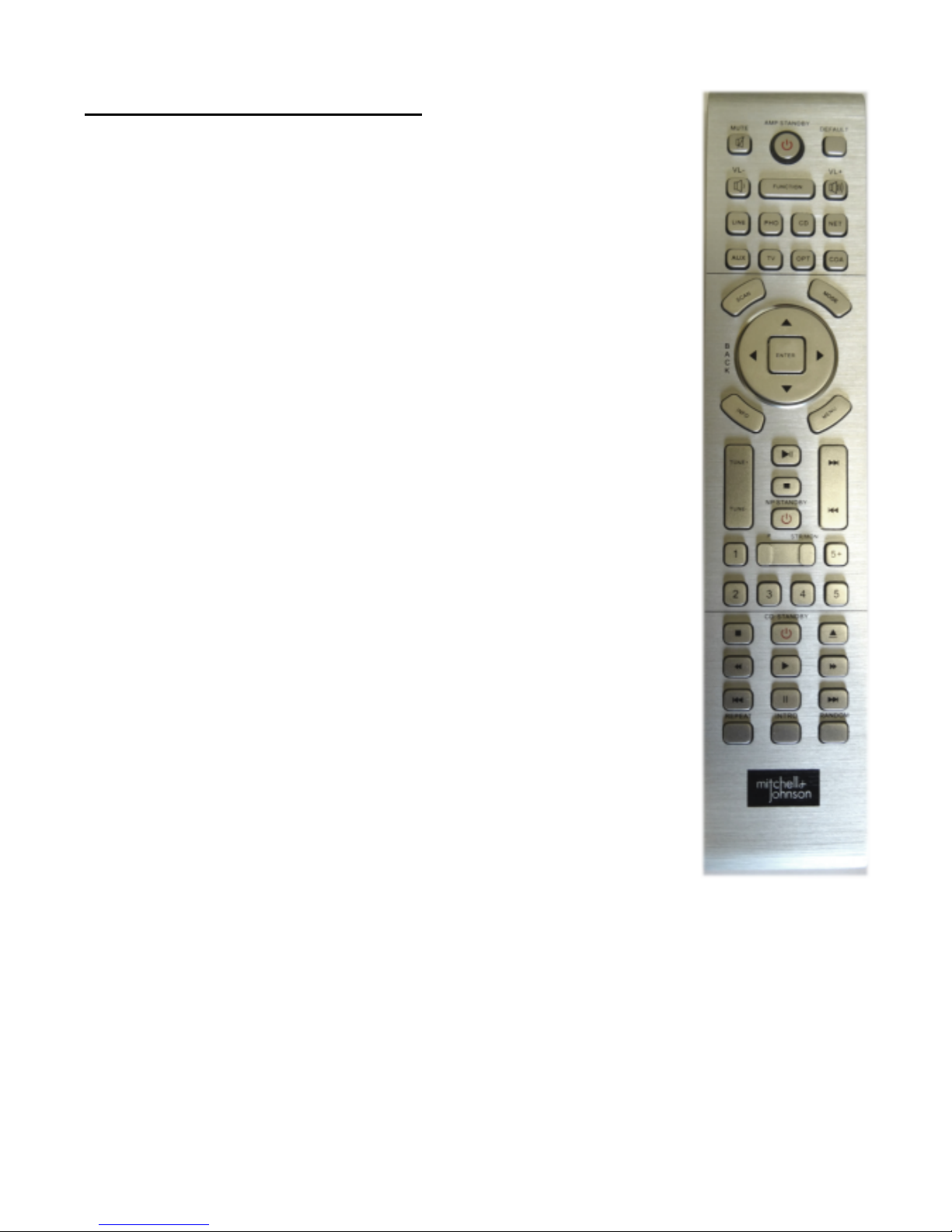
Mitchell & Johnson remote control
The remote control is designed to operate both the primary functions of the
Mitchell and Johnson pre/power and those of a Mitchell and Johnson CD
player
POWER: The top red power button toggles the unit between standby and
power on.
MUTE: Pressing the MUTE button once while the system is playing will cause
the volume to rapidly fade to zero.
A second push of the button will restore the volume level to its previous setting.
INPUT: The input buttons select the pre-allocated input sources as shown on
page 15.
VOLUME: Two buttons, + for up and - for down, control the volume. Short
presses on the VOLUME buttons will change the volume in small increments.
Press and hold the volume + or - buttons to smoothly raise or lower the volume.
The CD control buttons allow control of various functions on a Leema CD player.
TRAY: Opens and closes the CD tray
PLAY/PAUSE: Press once to play the CD, press again to pause. To resume
playback, press the PLAY/PAUSE button again.
STOP: Pushing the STOP button will terminate the playback and stop the CD from spining.
Page 15

15
Setup Menu
1> HT DIRECT INPUT
This menu defines the input designated as the Home Theatre input. This input can be assigned as the front left and right channel input source to be used in a Home Cinema Setup, usually from a home cinema processor or a suitable player with integrated surround
sound decoding.
Options:
1. HT Input not used.
2. HT Input xxxxxx
Explanation: When set to “not used”, the HT button on the remote does not function and
the HT selection is removed from the input selection list.
When HT is set, the selected input is allocated to the HT direct button and appears as the
home theatre input.
The HT volume only ramps up to fixed unity gain when HT mode is enabled from the remote control or from the input selection knob.
2> INPUT VOLUME DROP
Options:
1. Volume drops to a low/safe level when an input source is changed.
2. Volume remains at the current set level when an input source is changed.
Explanation: Mitchell & Johnson pre-amplifier has a large number of inputs, including
a phono stage, and multiple digital inputs
It would be possible to inadvertently switch between a low volume level source such as
classical music, via Bluetooth, to death metal music coming from a disk player.
The Mitchell and Johnson pre-amplifier can be set to lower the volume between input
selections (option 1 above) in order to avoid any such sudden changes in volume.
Page 16

16
Setup Menus Continued
3> DISPLAY BRIGHTNESS
Explanation: The brightness of the display can be adjusted between 5% and 95%.
The brightness will revert to a high level when navigating menus and revert to the User selected level in normal operation.
4> SET LCD OFF TIMER
Options:
1. LCD ALWAYS ON
2. OFF IN 5 SECONDS
3. OFF IN 10 SECONDS
4. OFF IN 30 SECONDS
Explanation: The LCD display can be set to automatically turn off after a preset period of
time following a command such as changing input or adjusting the volume. The display will
reactivate upon such an action then turn off following the preset period defined in the menu.
Page 17

17
5> INPUT NAMES: All input names are fully editable.
Explanation : The rear panel is labeled Optical IN 1, IN 2, IN 3, etc. These are the default names
used by the firmware, however, the displayed name may be changed as the user requires to make
it easier to identify an audio source.
For example, if a satellite receiver is connected to the Optical Input 1, this input could be renamed
to 'SAT'. Input names can be up to ten characters long.
EDITING AN INPUT NAME
Press the VOLUME/MENU knob for 5 seconds.
Using the VOLUME/MENU knob, locate item 5, "INPUT NAMES" and select by pressing.
Rotating the VOLUME/MENU knob, locate the input name to be edited, again, press the select
button.
The display will now show:
EDIT :<input name>
ALIAS :<Original name>
Notice that the first letter of the input name is flashing as a block.
To change the letter, press select. The letter will now be underlined.
Rotating the INPUT/NAV Knob will scroll through the available letters and symbols.
These are:- # ABCDEFGHIJKLMNOPQRSTUVWXYZ0123456789\-+:,.
When the required letter or symbol has been located, press the Select Button. This will return the
display to a flashing block. The INPUT/NAV knob can now be used to locate the next letter to edit.
Repeat the process until the name is displayed as required.
Finally, press the VOLUME/MENU button for 5 seconds to exit the MENU function. During the edit
process, the original name (as used on the rear panel) is shown as ALIAS for reference.
Page 18

18
6> SYSTEM RESET
Options:
1: CANCEL AND EXIT
2: LEAVE NAMES
3: FACTORY RESET
Explanation > Allows the system to be quickly reset to factory defaults.
Option 1 will not reset and will exit the reset sub menu.
Option 2 will reset all menu options but leave edited input names.
Option 3 will reset all menu options and reset input names to defaults.
7> Phone Cartridge Selection
Options:
1: Moving Magnet Cartridge
2: Moving Coil Cartridge
Explanation: There are two types of phono cartridge in common circulation,
Moving Magnet and Moving Coil.
Moving Coil cartridges have a very low output voltage which requires an extra gain stage
to be switched in to the circuit. This can be achieved by selecting option two.
Setup Menus Advanced, Cont’d
Page 19

19
USB ASYNCHRONOUS
CONNECTION
The USB interface uses an XMOS based solution. Linux or Apple operating systems will automatical-
ly connect for high speed audio, though the M&J unit will have to be selected as the audio player in
the computer settings.
Windows 10 creators update also has the XMOS driver embedded.
Earlier versions of Windows will require a driver, but we strongly recommend using Windows 10 for
high speed audio playback.
If using an earlier version of Windows, please contact Mitchell & Johnson for advice.
Page 20

20
Introduction
Mitchell & Johnsons USB board allows for state of the art connection via USB.
For correct operation of the USB interface with Microsoft Windows machines, a USB driver
must be downloaded, installed and configured. Please see page 35 for instructions.
Apple OSX® and Linux® operating systems do not require an additional driver.
They will however require their respective audio playback devices to be set to”XMOS”as
the default.
Asynchronous USB
In a conventional USB playback scenario, the computer varies the speed of the digital audio stream emanating from it’s USB port, itself. The DAC has no option but to slavishly
follow this variable data rate. This is not a suitable method for producing high quality audio
since it results in high jitter which in turn results in high distortion.
Asynchronous USB playback requires the DAC to accurately regulate the data output
speed of the computer to practically eliminate jitter based distortion.
In practice this is a very complex task and requires the computer to have a free USB 2.0
port, connected to the DAC via a suitable high speed USB 2.0 cable.
Mitchell & Johnsons 800 series pre-amp uses a USB high speed device which upon connection, invokes the USB port’s high speed mode. This mode is only available under USB
2.0.
Windows does not natively support High data rate audio formats, hence the need for a driver to be installed.
UPDATE…..Windows 10 creators update now includes the XMOS driver as standard.
Page 21

21
Audio Specifications
Digital inputs >
Optical > Capable of handling up to 24 bit 192kHz PCM stereo audio.
Co-Axial > Capable of handling up to 24 bit 192kHz PCM stereo audio.
Async USB > Capable of handling up to 24 bit 192kHz PCM stereo audio,
Plus DSD1X and 2X.
Phono input >
Moving magnet gain 36dB
Moving coil gain 62dB
Frequency response +/- 0.1dB ref RIAA curve 20Hz to 20khz
Load characteristics Moving magnet 47k Ohm + 100pF
Load characteristics Moving coil 90 Ohms + 1nF
Input sensitivity Moving magnet 4mV RMS for 250mV RMS out at 1kHz
Input sensitivity Moving coil 180uV RMS for 250mV RMS out at 1kHz
Headroom Greater than +26dB at 1kHz
Specifications subject to change without notice.
Page 22
22
800 SERIES
POWER AMPLIFIER
INSTRUCTIONS
Page 23
23
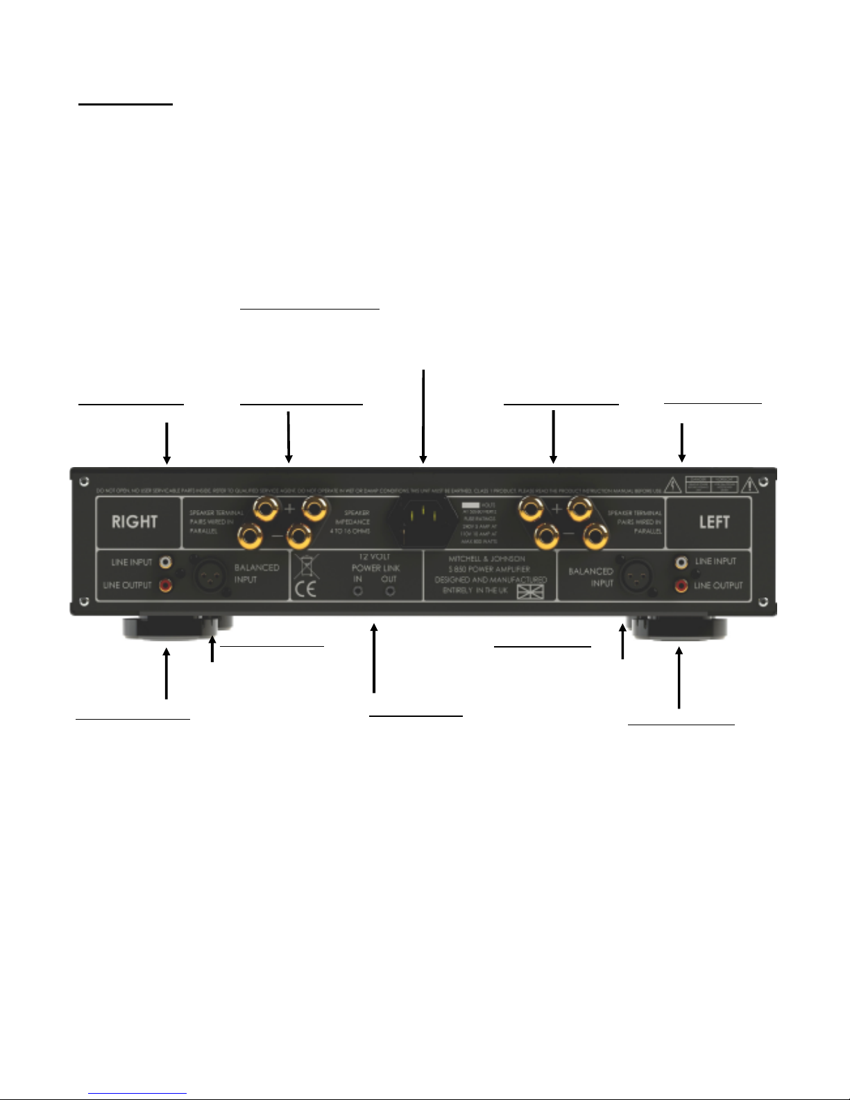
Power Inlet and fuse ratings
Please ensure that the specification indicated adjacent to the connector is correct
for your area.
This will either be 230VAC or 115VAC.
Analogue Output Left
Use for Bi-Wiring
Rear Panel
Balanced input Left
From Pre Amplifier
Connections comply with
European standard pin
polarity wiring
12 volt power links
Used to link units together
for synchronised on/off
Balanced input Right
From Pre Amplifier
Connections comply with
European standard pin
polarity wiring
Analogue Output Right
Use for Bi-Wiring
Analogue Input Right
From Pre-Amplifier
Analogue Input Left
From Pre-Amplifier
Speaker Terminals Right
Speaker Terminals Left
Page 24
24
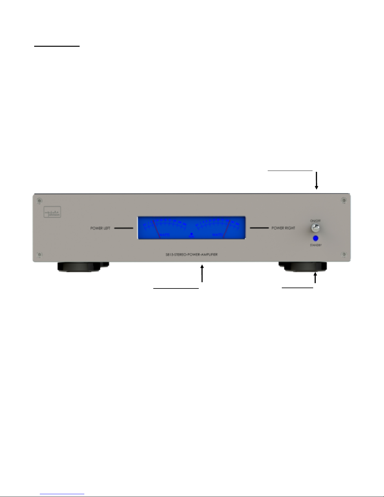
Power on/off Switch
Output Level Meters
Front Panel
Standby Light
Page 25

25
Mitchell & Johnson 800 series Power Amplifier Overview
The Mitchell & Johnson 800 series power amplifier is a class leading product, capable of superb
performance at the heart of an audiophile stereo system. It employs an analogue class A/B
topology using 6 high power output transistors per channel for reliability and tremendous current
delivery.
Precision mechanical meters show the amplifiers output in real time.
Connections
Input Connections
Analogue> The Mitchell & Johnson 800 series power amplifiers analogue inputs should only be
connected to the analogue outputs (usually marked left/right and colour coded white/red) from a
source component such as a pre-amplifier that has volume control.
Balanced > High end sources often feature this kind of connection. It does not offer any inherent
advantage over unbalanced connections in short cables but it does offer better signal to noise and
hum rejection in long cables where the components are sited some distance apart.
Page 26

26
Connections continued
Output connections
PRE OUT > Dual stereo line outputs are provided. These outputs are a loop through of the power
amplifier input and can be used for bi-amplifying, where one stereo amplifier is used to drive the
bass units and another stereo amplifier is used to drive the midrange/tweeter units.
The loudspeakers must be suitable for bi-amping. This is normally the case where there are two
pairs of binding posts on the rear of the loudspeakers. It is vital to remove the links on the rear of
the speakers, otherwise the amplifiers will be connected to each other, which will result in
considerable damage.
Please contact Mitchell and Johnson Ltd. for advice.
Loudspeaker Terminals
There are four pairs of shrouded loudspeaker terminals on the Amplifiers rear panel, two pairs for
the left loudspeaker and two pairs for the right loudspeaker.
They accept 4mm banana type plugs, suitable spade connectors or bare wires.
Pay close attention to polarity. The red amplifier terminal must connect to the red terminal on the
loudspeaker and the black amplifier terminal to the black loudspeaker terminal.
Dual terminals are provided to allow for easy bi-wiring. Two sets of loudspeaker cables will be required. Simply connect the bottom pair of terminals on the loudspeakers to one of the terminal
pairs on the correct side of the amplifier, then connect a second cable to the top pair of terminals
on the loudspeaker and to the second pair of amplifier terminals.
Repeat for the other channel.
Ensure that the loudspeakers terminal links have been removed.
The dual terminals are wired in parallel inside the amplifier so please ensure that the total load is 4
Ohms or above.
Cables
Never underestimate the importance of good quality speaker cables. Bell wire or lighting flex will
not do. Cables can be very synergistic.
The higher the system resolution, the more easily differences between cables can be discerned.
Page 27

27
Audio Specifications
Power Output: 8 ohms: 150 Watts RMS per channel,
4 ohms:280 Watts RMS per channel.
Minimum load impedance: 4 ohms.
Output Current: greater than 20 Amps
Frequency response +0/-3dB @ 1W: 5Hz - 100kHz
Noise (A weighted, volume control minimum): -100dBm
Signal to Noise ratio (A weighted, ref: 285 Watts RMS 4 ohms): -104dB
THD (10 Watts RMS 4 ohms, 1KHz): 0.006%
THD (Max output before clipping, 4 ohms, 1KHz): 0.006%
Maximum DC offset: +/- 50mV
Sensitivity for maximum output (CD input): 565mV RMS
Sensitivity for maximum output (other inputs): 311mV RMS
Output Impedance: 0.05 ohms Damping Factor (8 ohms): 160
Weight: 16kg
Specifications subject to change without notice.
Page 28

28
Mitchell & Johnson Limited,
16, Severn Farm Industrial Estate,
Welshpool, Montgomeryshire,
Wales, UK, SY21 7DF
email: [email protected]
Web: www.mitchellandjohnson.com
 Loading...