

Page 1
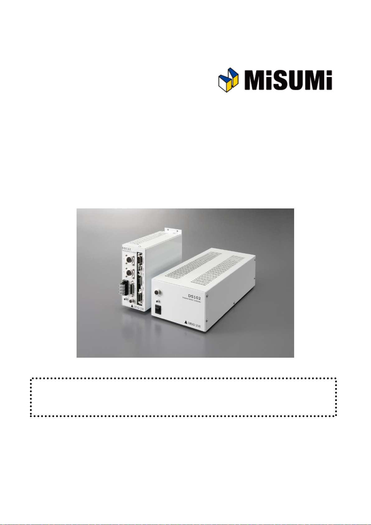
Stepping Motor Controller
MSCTL102 Series/MSCTL112 Series Operation Manual
Ver 1.01 (02.13.2015)
Remarks
MSCTL102/112 Series(MISUMI products) are same as DS102/112 Series that are made by Suruga Seiki.
All of DS102/112 series that are mentioned in the operation manual indicate MSCTL102/112.
MISUMI CO., LTD.
SURUGA SEIKI CO., LTD.
Page 2

2
Index
1.INTRODUCTION ................................................................................................................................................................................. 5
1.1 FOR YOUR SAFETY .............................................................................................................................................................................. 5
1.2 PRODUCT OUTLINE / FEATURES ................................................................................................................................................... 7
1.3 SYSTEM CONFIGURATION EXAMPLE .............................................................................................................................................. 9
1.3.1 CONTROL WITH PLC................................................................................................................................................................. 9
1.3.2 CONTROLLED BY PC ............................................................................................................................................................. 10
1.4 ACCESSORIES .................................................................................................................................................................................... 11
2.SET-UP AND EXAMPLE OF USE ................................................................................................................................ 11
2.1 SET UP BEFORE USE ....................................................................................................................................................................... 11
2.1.1 CONNECTING ............................................................................................................................................................................ 12
2.1.2 USB DRIVER INSTALL ......................................................................................................................................................... 15
2.1.3 INSTALLATION FOR CONTROL SOFTWARE DS102/112(DSCONTROL-WIN) ..................................... 19
2.1.4 ADJUSTMENT SYSTEM PARAMETER ............................................................................................................................... 23
2.1.5 OPERATION CHECK ................................................................................................................................................................ 25
2.2 SYSTEM ARCHITECTURE ............................................................................................................................................................... 27
2.2.1 MOVEMENT BETWEEN EACH TEACHING POSITION..................................................................................................... 27
2.2.2 EASY RETURN TO ORIGIN POSITION .................................................................................................................................. 34
2.2.3 CONTROL BY EXTERNAL SIGNAL ...................................................................................................................................... 43
2.2.4 EXTERNAL DEVICE CONTROL WITH GENERALI/O. ................................................................................................. 54
2.2.5 MOVE TO ARBITRARY COORDINATE ................................................................................................................................ 56
2.2.6 CONTROLLED OVER 3 AXES .............................................................................................................................................. 58
3.SPEC AND FUNCTION........................................................................................................................................................... 59
3.1 BASIC SPEC ...................................................................................................................................................................................... 59
3.2 PART NAME AND FUNCTIONS ..................................................................................................................................................... 60
3.3 SETTING .................................................................................................................................................................................................. 63
3.4 EXTERNAL INTERFACE ...................................................................................................................................................................... 64
3.4.1 LINK CONNECTION(LINK) ................................................................................................................................................... 64
3.4.2 CONTROL INPUT/OUTPUT(CNT-I/O) ........................................................................................................................ 65
3.4.3 GENERAL I/O(I/O)( OPTION) ........................................................................................................................................ 68
3.4.4 EMERGENCY STOP INPUT(EMS) .................................................................................................................................... 70
3.4.5 STAGE INTERFACE ..................................................................................................................................................................... 70
3.5 DRIVER DIVISION NUMBER SETTING .............................................................................................................................................. 71
3.5.1 OPEN AND SHUT ........................................................................................................................................................................ 71
3.5.2 SETTING DIVISION NUMBER ..................................................................................................................................................... 71
3.6 SMOOTH DRIVE FUNCTION(ONLY MS TYPE) ...................................................................................................................... 72
3.7 UNITS SETTING FUNCTION ............................................................................................................................................................... 73
3.8 SPEED SETTING(SPEED TABLE) .............................................................................................................................................. 74
3.9 FUNCTION OF ORIGIN RETURN ........................................................................................................................................................ 77
3.10 LINEAR INTERPOLATING FUNCTION ........................................................................................................................................... 83
3.10.1 LINEAR INTERPOLATING(RELATIVE VALUE) ........................................................................................................... 83
3.10.2 LINEAR INTERPOLATING(ABSOLUTE VALUE) ........................................................................................................ 83
3.11 TEACHING FUNCTION ..................................................................................................................................................................... 84
3.12 PROGRAM FUNCTION ..................................................................................................................................................................... 84
Page 3

3
4.OPERATION AND CONTROL METHOD .................................................................................................................. 85
4.1 OPERATION BY THE HANDY TERMINAL ...................................................................................................................................... 85
4.1.1 INITIAL SCREEN ............................................................................................................................................................................ 85
4.1.2 TRANSITION MODE ..................................................................................................................................................................... 86
4.1.3 DRIVING MODE SELECT(JOG KEY) ............................................................................................................................. 87
4.1.3.1 CONTINUOUS DRIVING MODE(CNT:CONTINUE MODE) ............................................................................ 87
4.1.3.2 UNIFORM PULSE DRIVING MODE(STP: STEP MODE) ................................................................................ 87
4.1.3.3 ABSOLUTE VALUE DRIVING MODE(ABS: ABSOLUTE MODE) ............................................................... 88
4.1.3.4 ORIGIN RETURN MODE(ORG: ORIGIN MODE) ............................................................................................... 88
4.1.3.5 HOME POSITION RETURN MODE(HOM:HOME) .......................................................................................... 88
4.1.4 MENU SELECT(MENU KEY) .............................................................................................................................................. 89
4.1.4.1 PARAMETER MODE(PRM) ....................................................................................................................................... 89
4.1.4.2 PROGRAM DRIVING MODE(PRG) ......................................................................................................................... 98
4.1.4.3 TEACHING MODE (TCH) ......................................................................................................................................... 99
4.1.4.4 GENERAL MONITOR(IN) ....................................................................................................................................... 102
4.1.4.5 GENERAL OUTPUT CONTROL(OUT) .............................................................................................................. 102
4.1.5 OTHER FUNCTION .................................................................................................................................................................. 103
4.1.5.1 CHANGE THE SPEED TABLE(SPD KEY)....................................................................................................... 103
4.1.5.2 CHANGE THE AXIS(LINK KEY) ............................................................................................................................ 103
4.1.5.3 CHANGES CURRENT POSITION(POS KEY) ................................................................................................... 103
4.1.5.4 VERSION CONFIRMATION, PARAMETER RESET .................................................................................................. 104
4.2 DS102/112 CONTROLLED SOFTWARE(DSCONTROL-WIN) ...................................................................... 105
4.2.1 DSCONTROL-WIN START-UP ................................................................................................................................... 105
4.2.2 PARAMETER SET-UP ............................................................................................................................................................ 105
4.2.3 JOG DRIVING ............................................................................................................................................................................. 107
4.2.4 TEACHING ................................................................................................................................................................................. 110
4.2.5 DRIVING PROGRAM ................................................................................................................................................................ 112
4.2.6 I/O MONITOR ..................................................................................................................................................................... 118
4.3 USER PROGRAM PROCESSING ................................................................................................................................................... 119
4.3.1 RS232C ................................................................................................................................................................................ 119
4.3.2 USB ........................................................................................................................................................................................... 120
4.3.3 DELIMITER .................................................................................................................................................................................. 122
4.3.4 TYPES OF COMMUNICATION COMMAND ........................................................................................................................ 123
4.3.5 DETAILS OF COMMUNICATION COMMAND .................................................................................................................. 135
4.3.5.1 AXIS SPECIFICATION COMMAND .............................................................................................................................. 135
4.3.5.2 PARAMETER SETTING COMMAND ........................................................................................................................... 135
4.3.5.3 MEMORY SW SETTING COMMAND........................................................................................................................ 139
4.3.5.4 SPEED TABLE SETTING COMMAND ...................................................................................................................... 140
4.3.5.5 WRITE COMMAND ......................................................................................................................................................... 141
4.3.5.6 DRIVING COMMAND ...................................................................................................................................................... 141
4.3.5.7 STOP COMMAND ........................................................................................................................................................... 142
4.3.5.8 PARAMETER SETTING REQUEST COMMAND .................................................................................................... 143
4.3.5.9 MEMORY SW SETTING REQUEST COMMAND .................................................................................................. 145
4.3.5.10 SPEED TABLE SETTING REQUEST COMMAND .............................................................................................. 147
4.3.5.11 STATUS REQUEST COMMAND............................................................................................................................. 147
4.3.5.12 GENERAL I/O COMMAND ....................................................................................................................................... 152
4.3.6 PROGRAM DRIVING DEDICATED COMMAND ............................................................................................................... 153
4.3.7 ERROR CODE ........................................................................................................................................................................... 156
Page 4

4
5.CHECKOUT ..................................................................................................................................................................................... 157
6.FAULT DIAGNOSIS AND SOLUTION ...................................................................................................................... 157
7.WARRANTY & CUSTOMER SERVICE.................................................................................................................... 158
● APPENDIX ............................................................................................................................................................................................... 159
■ DIP SWITCH SET ............................................................................................................................................................................................. 159
■ DS102 EXTERNALS .................................................................................................................................................................................... 160
■ DS112 EXTERNALS .................................................................................................................................................................................... 161
■ CONTROL I/O CABLE(MODEL:DS100-CNT-2) ............................................................................................................... 162
■ GENERAL I/O CABLE(MODEL:DS100-IO-2) ................................................................................................................... 163
■ SELECTION OF A PROGRAM NUMBER BY CNT-IO ........................................................................................................................ 164
■ SELECTION OF A TEACHING NUMBER BY CNT-IO ........................................................................................................................ 164
Page 5
5
Cautions
!
1.INTRODUCTION
Thank you for purchasing this series Stepping Motor Controller.
1.1 For Your Safety
For Proper use, please read this operation manual thoroughly prior to using this product.
means the PROHIBITATION.
Please look after instructions shown here by all means.
Failure to use controller, may be hurt or suffer material damage.
・Basic cautions
・ Connect a power cable to a power outlet which comes with protective earth terminal, In case of
using an extension cable without protective earth terminal, protective earth will be of no effect.
・Cable
・When you unplug a power cable, turn off a power switch.
・When it supplies DS112 Series with a power supply, please be careful not to make a mistake in
polarity.
・Operating Environment
・To avoid as follows.:
-Areas that have much dust or metallic particles
-Directly under sunlight
-Near fire
-Much vibration
-Watery or oily place
-Wonky place
-Place with Corrosive Gas and Flammable Gas
・Storage
Please unplug a power from the outlet when
It doesn’t use for a long time, and you move this product..
A fire and the accident of the electric shock etc. are prevented.
Page 6
6
Caution
!
・Power Source
・Please DO NOT connect the DS102 series besides the power supply outlet of interchange 100~
240V (AC100~240V 50/60Hz)
・Please supply direct 24V(DC24V±10%)power supply for DS112 series.
In order to avoid damage to controller, DO NOT use any input voltage or frequency over
the specifications.
・Resolution of the product/Remodeling
・ Please DO NOT perform the resolution of the product, remodeling, the
unfair repair.
・ Please contact us for correct information if needed.
・Repair Service
・ In the case of the following, please disconnect the plug promptly and then
contact your supplier.
-When there are some strange sound, smelling and smoke.
-When a power supply cable damaged.
-When spilled water on the equipment and foreign materials entered
inside.
-When dropped the equipment and was damaged with a cabinet.
Page 7
7
1.2 Product Outline / Features
Computer
PLC
DC24V
AC100V
XY
DS112
Stepping Motor Controller
DS112
Stepping Motor Controller
DS102/DS112 series
AC100~240V
DC24V
Motorized stage
DS102/112
Controlled software:
DSCONTROL-WIN
DS102
Stepping Motor
Controller
DS102
Suruga Seiki
Standard
DT100
Handyterminal
DT100
I/O for
controlled
USB
or
RS232C
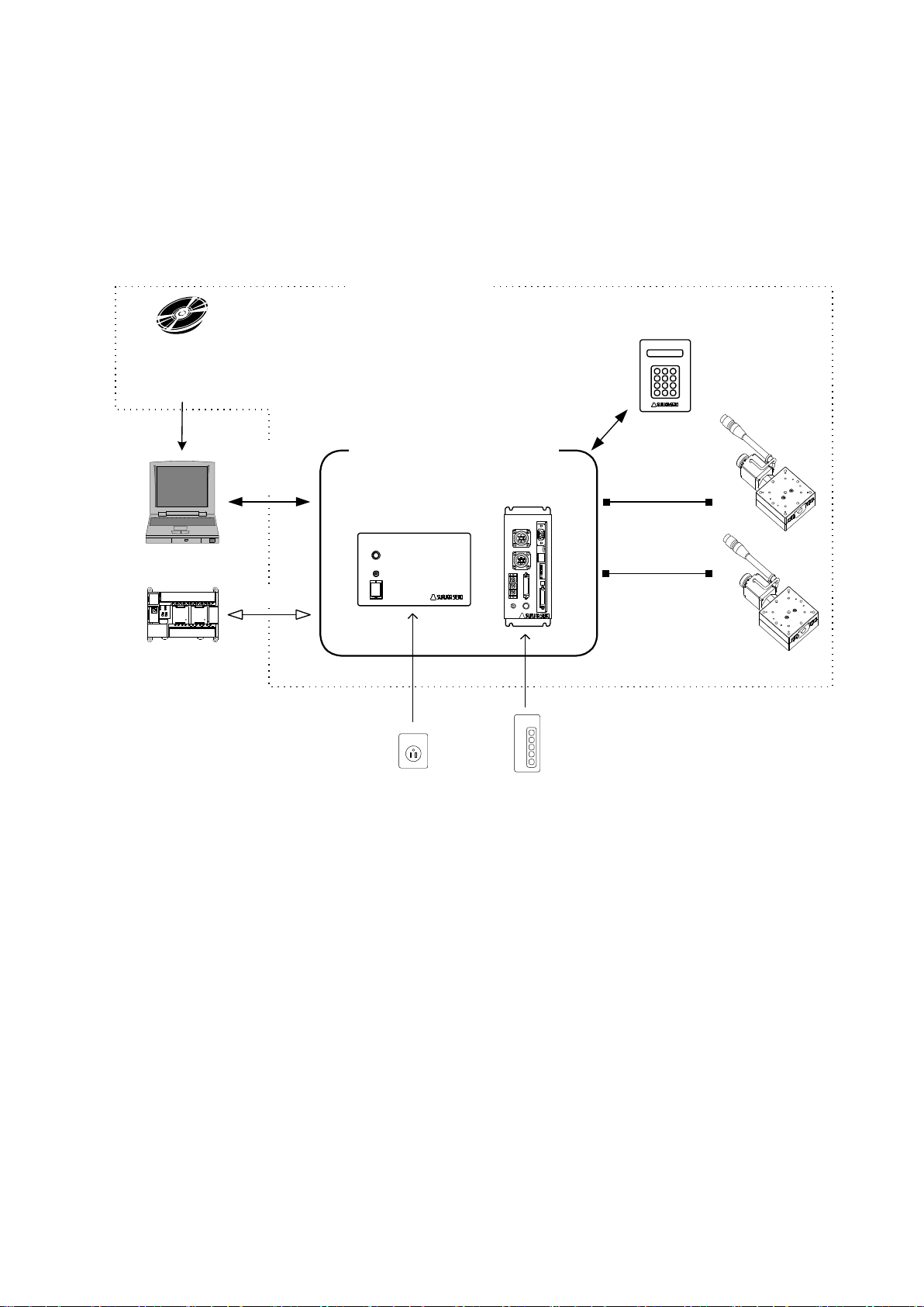
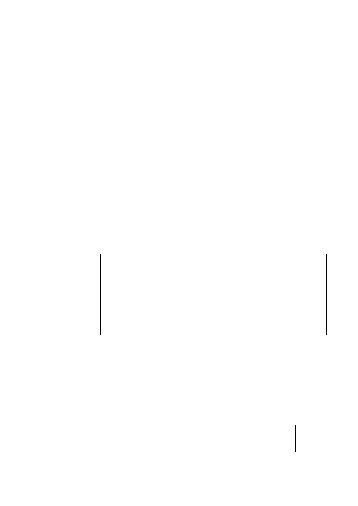
DS102/DS112 series is stepping motor controller with 2 axes for not only R&D but also units and
manufacturing you can use what you want.
Product Outline
Page 8
8
Features
SURUGA Type
MISUMI Type
Input PS
Type of Drive
General I/O
DS102NR
MSCTL102
AC100~240V
±10%
50/60Hz
Normal (FULL/HALF)
-
DS102NR-IO
MSCTL102-IO
Input16, Output12
DS102MS
MCSTL102-MS
Microstep (16levels)
-
DS102MS-IO
MSCTL102-IO-MS
Input16, Output12
DS112NR
MSCTL112
DC24V ±10%
Normal (FULL/HALF)
-
DS112NR-IO
MSCTL112-IO
Input16, Output12
DS112MS
MCSTL112-MS
Microstep (16levels)
-
DS112MS-IO
MSCTL112-IO-MS
Input16, Output12
SURUGA Type
MISUMI Type
Cable length
Recital
DS100-LINK2-0.5
MSLINK2-0.5
0.5m
For 2 links
DS100-LINK3-0.5
MSLINK3-0.5
0.5m
For 3 links
DS100-CNT-2
MSCNT2
2m
For control I/O(one end loose)
DS100-IO-2
MSGP2
2m
For general I/O(one end loose)
D100-R9-2
MSRS232C
2m
RS232C cable
DS100-USB-1.8
MSUSB1.8
1.8m
USB Cable
SURUGA Type
MISUMI Type
Article name
DT100
HDT100
Handy Terminal
DSCONTROL-WIN
MSSOFT
DS102/112 controlled software
1. Controlled
・ 5 phase stepping motor is controlled by 2 axes
・ Linear interpolation of 2 axes
・ 2 types motor driver with normal(FULL/HALF) and micro-step(16 levels)
As a microstep type, it is possible to highly positioning control and low vibration with
Smooth drive function.
・ It is possible to control 6 axes with link function.
Up to 24 axes can be controlled with USB Hub.
2. Drive
・ Teaching point movement
・ Program Drive
・ Jog Drive
・ It is possible to memorize teaching point 64 points and 8 of programs.
3. Interface
・ Connected USB、RS232C
・ DS102/112 controlled software:DSCONTROL-WIN
・ Handy terminal:DT100
・ I/O for controlled
・ General I/O:Input16points、output12points (Option)
・ 2 types of PS/V AC100~240V、DC24V
【Line up products】
【Option Cable】
【Other Option】
Page 9
9
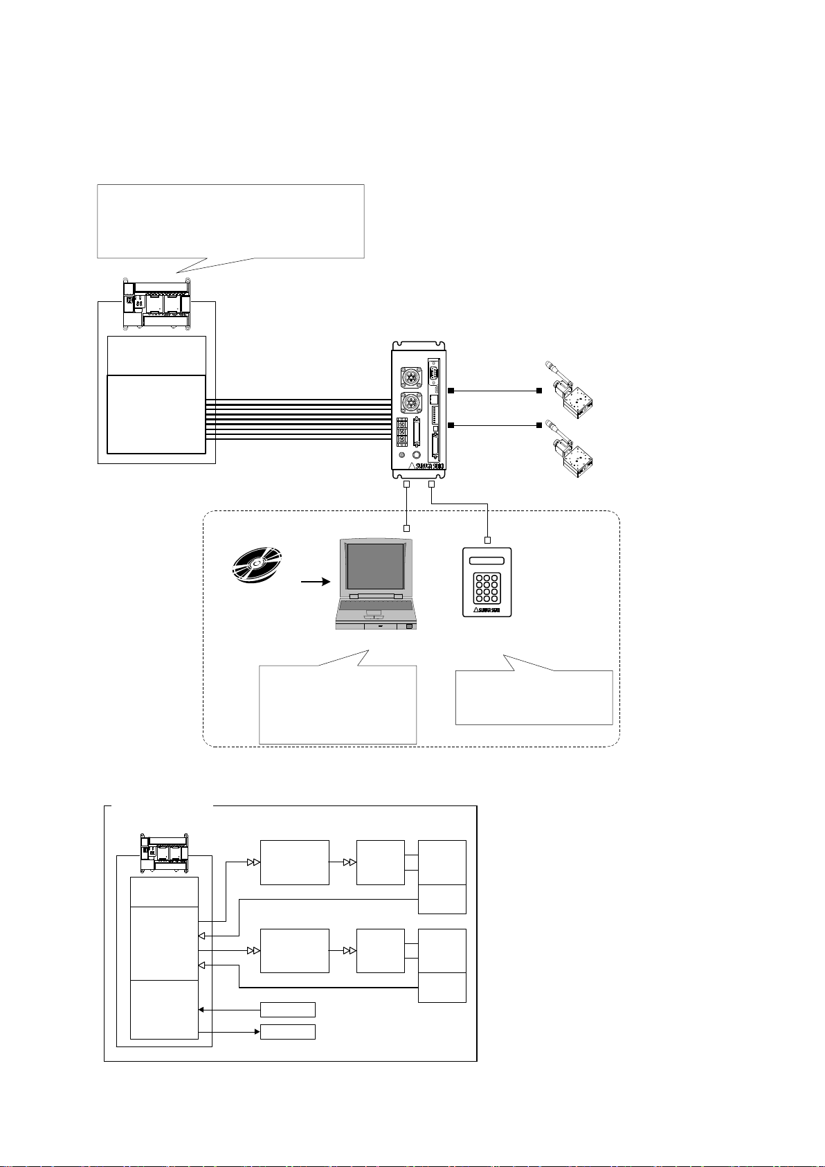
1.3 System configuration example
X axis
Motor driver
X axis motor
Guide ball
screw
Limit
Switch
Y axis
Motor driver
Y axis motor
Guide ball
screw
Limit
Switch
Position Control
Unit
CPU Unit
I/O Unit Sensor
Actuator
PLC
Former System
CPU Unit
I/O Unit
X Axis Stage
Y Axis Stage
PLC
XY
DS112
Stepping Motor Controller
DS112NR
Move the teaching point/Switch the program
drive
Teaching point number selected
Program number selected
Start/Stop
DS102/112
Controlled SoftWare:
DSCONTROL-WIN
・Move the teaching point/Switch the program drive.
・Teaching Point Number Selected.
・Program Number Selected
・Start
・Stop
・Set up the system parametor
・Memorized teaching points
・Programming and editing
・Operation check
・Back up data
PC
DT100
Handy Terminal
DT100
・Set up the system parametor
・Memorized teaching points
・Operation check
USB or RS232C
1.3.1 Control with PLC
Stages can be controlled with I/O units of PLC.
No need positioning units.
Page 10
10
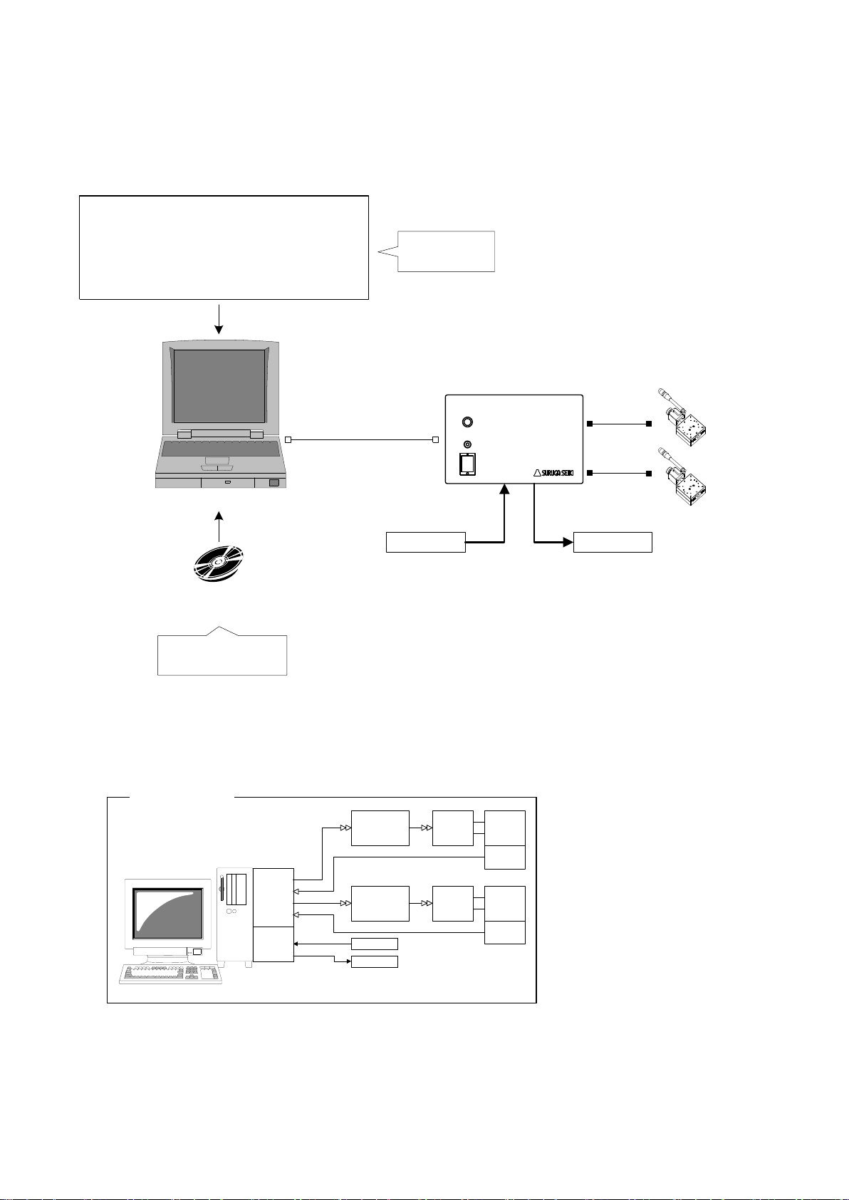
1.3.2 Controlled by PC
Motion
Control
Board
X Axis
Motor driver
X Axis
Motor
Guide
ball screw
Limit
Switch
Y Axis
Motor Driver
Y Axies
Motor
Guide
ball screw
Limit
Switch
I/O
Board
Sensor
Actuator
PC
Former set-up
Sensor Actuator
USB
or
RS-232C
X axis stage
Y axis stage
PC
General Input:
16points
General Output:
12points
DS102
Stepping Motor
Controller
DS102NR-IO
Use virtual COM port (Ex.:VB)
RS-232C communication application
MSComm1.Settings = "9600,N,8,1" ' Set up the port
MSComm1.CommPort = 1 ' Set up the port add.
MSComm1.PortOpen = True ' Open the port
' Move to 100 X axies
MSComm1.Output = "Axis1:Selsp 0:Goabs 100"
Original software
・Set up the system
parametor
・Operation check
・Cotrolled stage
・ControlI I/O
DS102/112
Control Software:
DSCONTROL-WIN
Easily controlled external machine by software.
No need motion control board and I/O board.
Page 11
11
1.4 Accessories
Operation check
・DS102 or DS112
・X axis stage ・Y axis stage
・Motor cable
・RS232C cable:DS100-R9-2
・USB cable:DS100-USB-1.8
・Power cable
・PC
※You must have another power supply
and power cable if you use DS112.
・USB driver CD-R
・DSCONTROL-WIN CD-R (Option)
Conecting
Install USB driver
Set up the system parametor
DS102/112 Control soft ware:
Install DSCONTROL-WIN
This included following goods. Please check when you open. If some parts missing, please let us
know.
・ DS102/DS112:1 PCS
・ Power cable(2m) :1 PCS(Only case of DS102)
・ CD-R(data of this Manual , USB Device driver) :1PCS
・ Manual(this documents) :1PCS
The power cable of DS102 attachment is exclusively for this machine.
2.Set-up and example of use
2.1 Set up before use
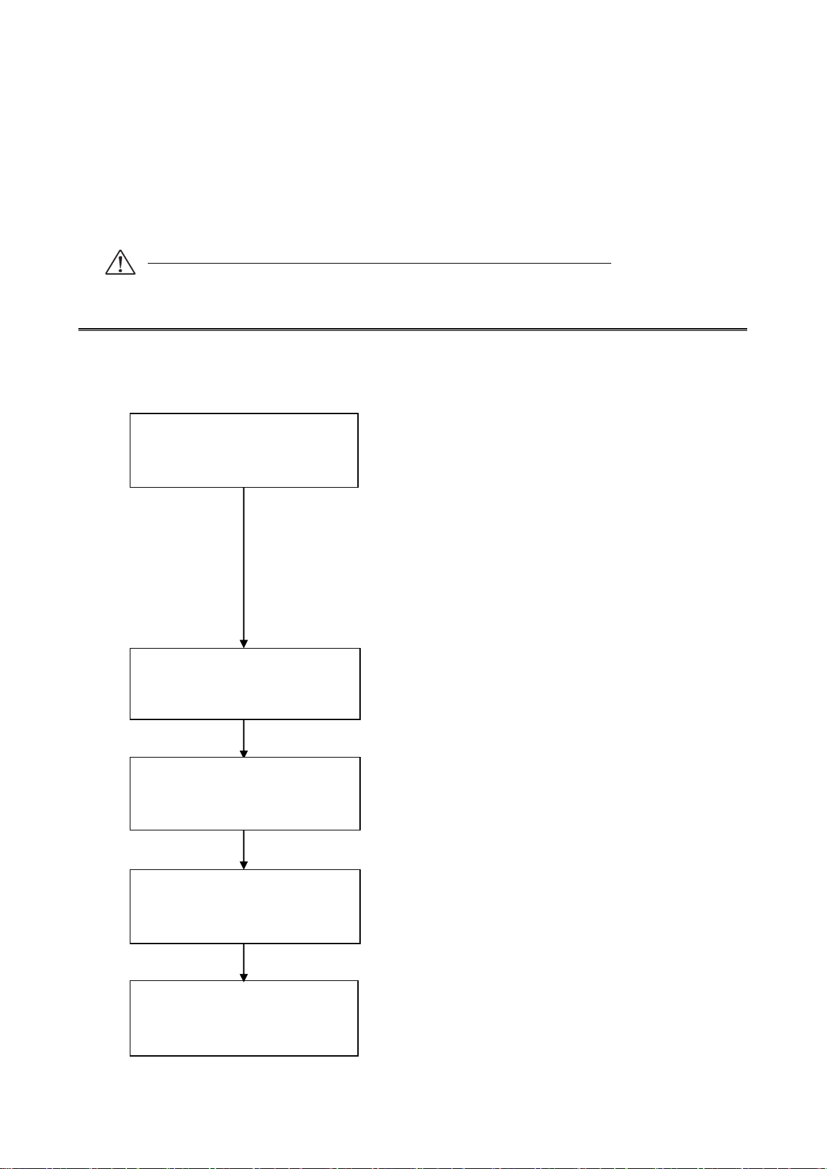
Shows flow before use DS102/DS112.(MISUMI Type: MSCTL102/MSCTL112)
Page 12

12
2.1.1 Connecting
I/O connector for
control
RS232C
X axis stage connector
General I/O
Connector
X Y
I/O
CNT-I/O EMS SW1 LINK USB RS232C
USB Connector
AC Inlet
Y axis stage connector
I/O
CNT-I/O
USB
RS232C
X
Y
TERMINAL
DS102
Stepping Motor Controller
Power
Connector for
Handy terminal
TERMINAL
Shows how to connect DS102/DS112
DS102
Page 13

13
DS102
Stepping Motor
Controller
X axis stageY axis stage
AC100V
AC100
~240V
USB Cable:
DS100-USB-1.8
USBRS232C
RS232C Cable:
D100-R9-2
or
XY
Motor Cable
16 pins series stages:
D214-1-□E,D214-1-□R
(MISUMI:SRCB□,SRCB□-R)
12 pins series stages:
D214-2-□E,D214-2-□R
(MISUMI:MSCB□,MSCB□-R)
D214-2-□EA,D214-2-□RA
(MISUMI:MS4CB□,MS4CB□-R)
Attached
Power Cable
① Connect X axis motor connector to X axis stage.
② Connect Y axis motor connector to Y axis stage.
③ Connect AC inlet and AC100~240V.
④ Connect USB connector to USB port of PC.
(Connect RS232C connector to PC if use RS232C)
Page 14
14
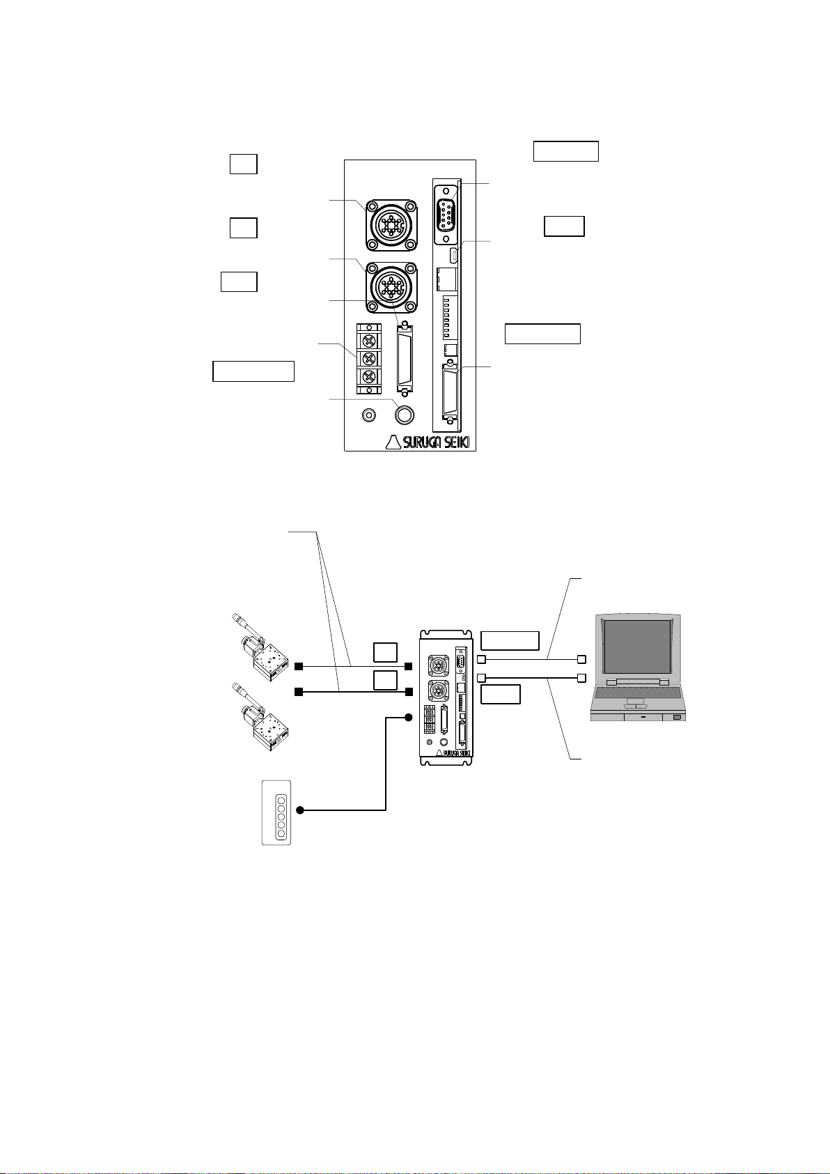
Use DS112
XY
TERMINAL
POWER
+24V
CNT-I/O EMS SW1 LINK USB RS232C
DS112
GNDFG
I/O
Y axis motor
connector
Terminal block for
power
General I/O
connector
Handy terminal
for connector
RS232C
connector
USB
connector
I/O connector for
control
Stepping Motor Controller
I/O
CNT-I/O
USB
RS232C
X
Y
TERMINAL
X axis motor
connector
X axis stage
Y axis stage
XY
DS112
Stepping Motor Controller
X
Y
USB cable:
DS100-USB-1.8
USB
RS232C
RS232C cable:
D100-R9-2
or
Motor cable
16pin series stage:
D214-1-□E,D214-1-□R
12pin series stage:
D214-2-□E,D214-2-□R
DC24V
DC24V
① Connect X axis motor connector to X axis stage.
② Connect Y axis motor connector to Y axis stage.
③ Connect terminal for power of DC24V to power supply(DC24V)
※ Must have DC24V power supply and cable
④ Connect USB connector to PC USB port.
(Connect RS232C connector to PC if use RS232C )
Page 15
15
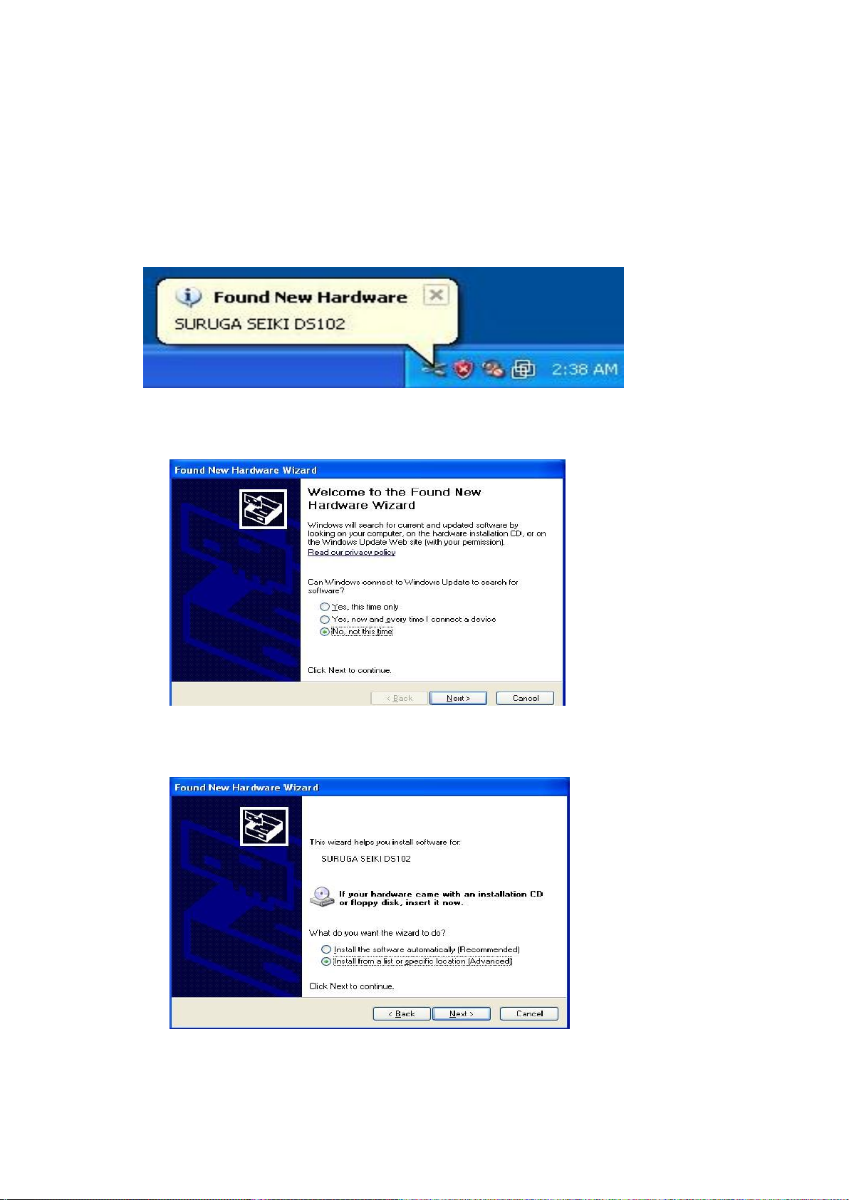
2.1.2 USB Driver Install
Shows how to install USB driver to PC(for XP).
① Switch on a computer and start Windows.
② Set up DS102/112 USB driver CD-ROM to computer drive.
③ Switch on DS102/112 and wait 5 seconds.
④ Connect computer USB port and DS102/112 USB connector.
When computer recognize to connect DS102/112, shows following messages.
⑤ At the detecting wizard of new hardware, choose [No, not this time]
and click [Next].
⑥ Select [Install from list or specific location (Advanced)] and click [Next].
Page 16
16
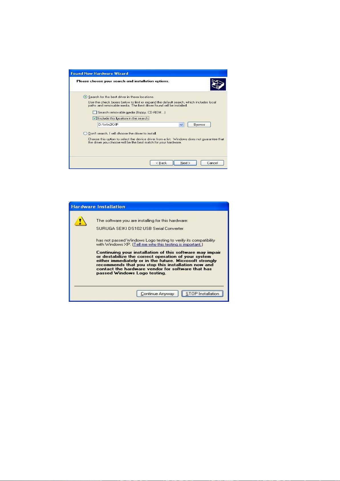
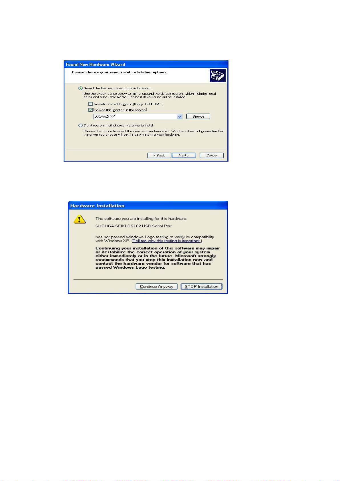
⑦ Check the [included this location in the search], push [Browse] and select [Win2KXP] then,
click [next].
Start the driver install.
⑧ Click the [Continue Anyway] when displays Hardware Installation.
Page 17
17
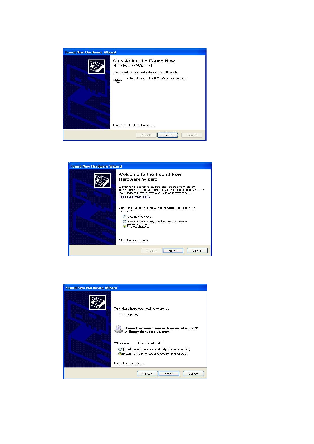
⑨ Click [finish]
Display the found new hardware wizard.
⑩ Select [No, not this time] and click [Next].
⑪ Select [Install from a list or specific location (advanced)] and click [Next].
Page 18
18
⑫ Check the [included this location in the search], push [Browse] and select [Win2KXP] then,
click [next].
Start the driver install.
⑬ Click the [Continue Anyway] when displays Hardware Installation.
Page 19

19
⑭ Click [finish]
Display the found new hardware wizard.
2.1.3 Installation for control software DS102/112(DSCONTROL-WIN)
Show how to install software (DS CONTROL-WIN) to control DS102/112 by PC.
① Insert CD-ROM of DSCONTROL-WIN inside PC drive.
② Double click on setup.exe in CD-ROM.
DSCONTROL-WIN installer start.s.
③ Click [next]
The screen below appears on PC.
Page 20
20
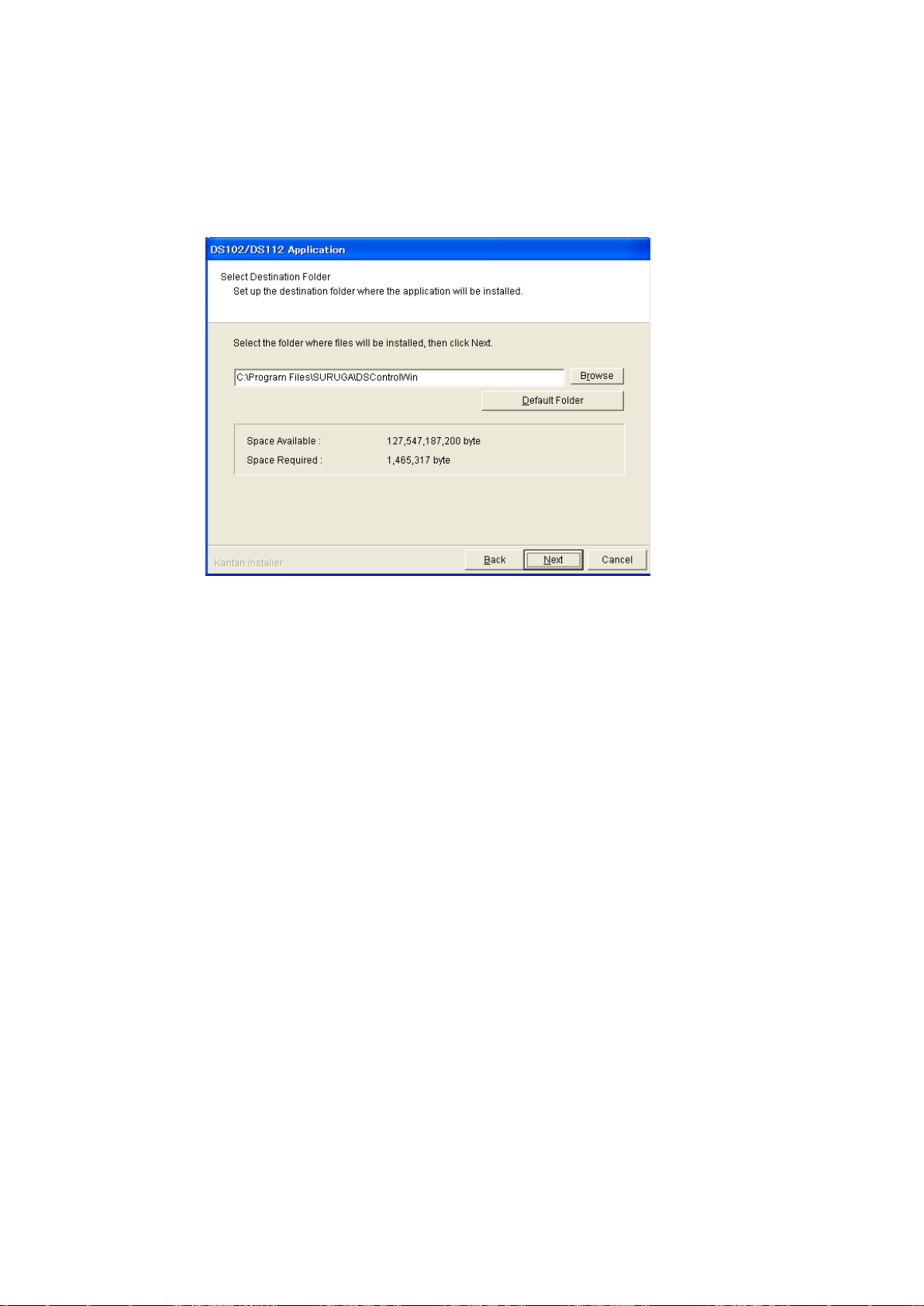
④ Select folder of installation then click {Next}
The screen shows folder selection
※On initial setting, installation folder is:\Program Files\SURUGA\DSControlWin.
Click [Next] in case of no required folder
Page 21
21
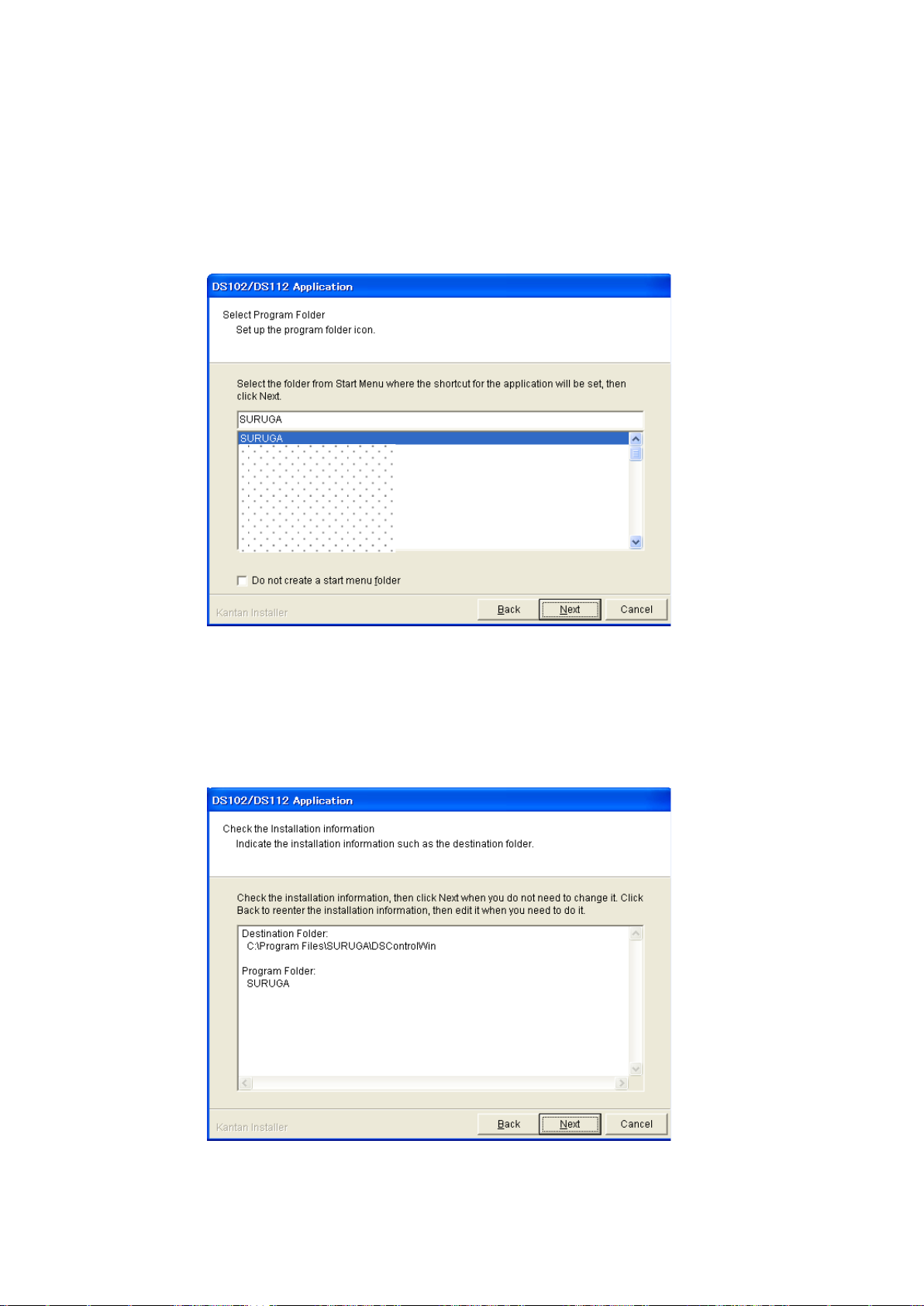
⑤ To prepared Program Shortcut, you need to select folder from list on START MENU then click
[Next]
The drawing below appears on PC screen
※On initial setting, Startmenu folder is DSControlWin.
Click [Next] in case of no required folder
⑥ Click [Next] after you confim installed contents
The screes scomes to [Information]
Page 22
22
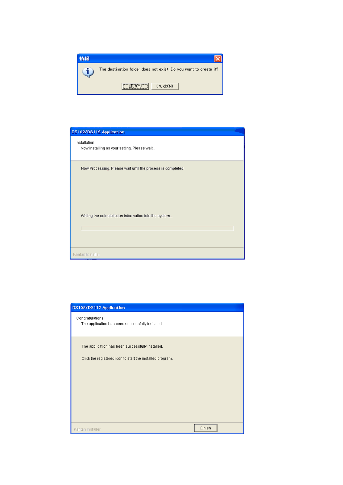
⑦ Click [YES]
※ No pop-up message appears if you already select folder
Installation begins
Installation complete.
⑧ Click [Finish]
Installing DSCONTROL-WIN completed.
Page 23
23
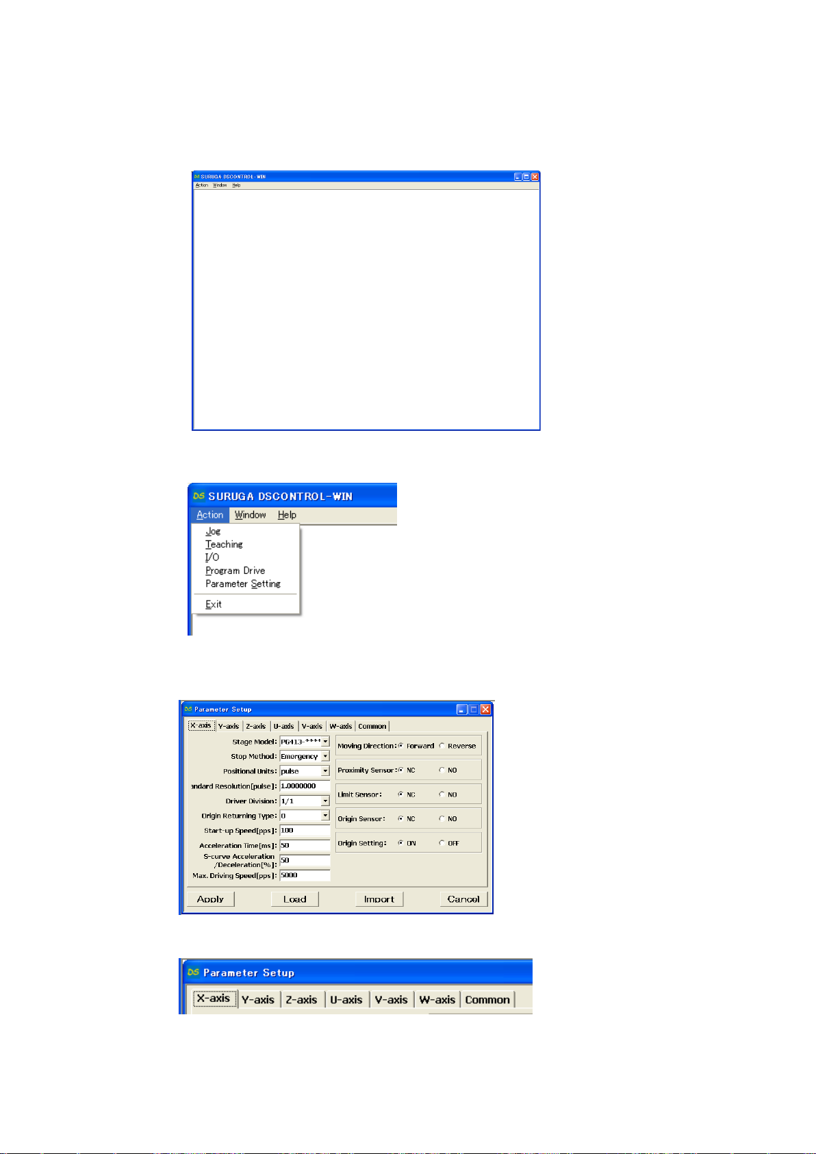
2.1.4 Adjustment system parameter
Shows how to set up system parameter by DSCONTROL-WIN
① Starts DSCONTROL-WIN
② Select [Parameter setting] in [Action]
Parameter setting appears on screen
③ Click on Tab you sellect
Page 24
24
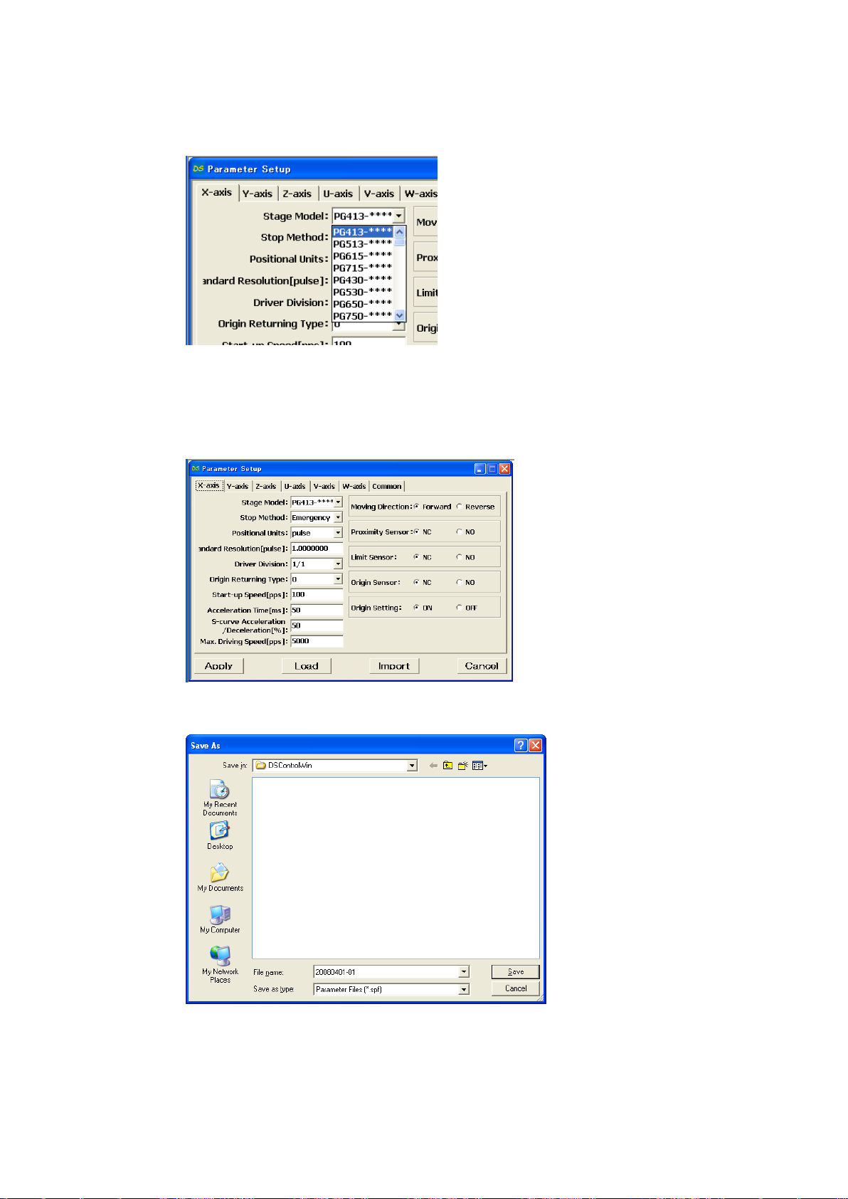
④ Select stage model you use from [Stage Model]
Initial value appears when you select stage model.
※ input direct value if we want to change initial value.
⑤ Select axis parameter by repeating ③~④ again.
⑥ Click [Apply].
Screen shows folder storing parameter.
⑦ Select folder and input file name then click [Save].
Parameter values are saved PC then forward values toward DS102/112.
※ Spf is automatically added.
Page 25
25
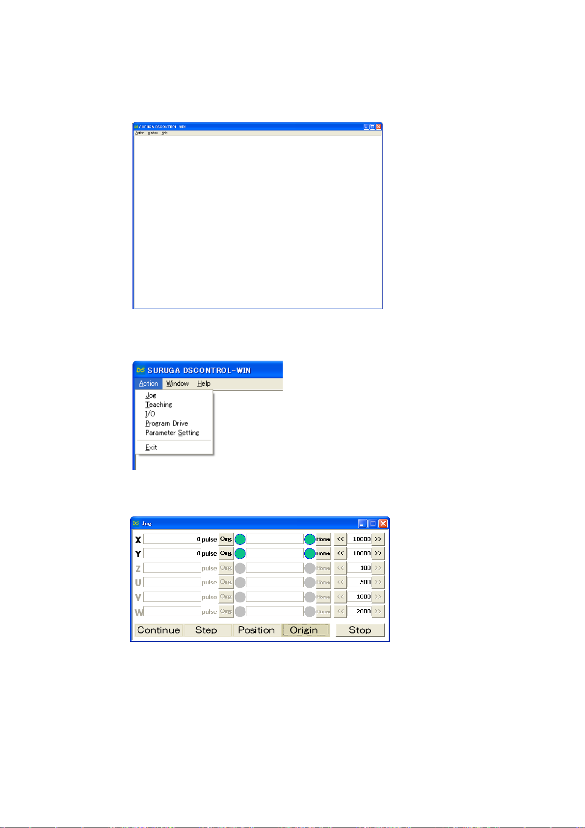
2.1.5 Operation check
Shows how to check operation.
① Starts DSCONTROL-WIN.
② Click [JOG] in [Action] on main menu
JOG dialog appears on screen.
③ Click [Origin]
[Org],[Home] appears.
④ Click [Org] on X axis
X stage return origin position.
Make sure X stage moves origin position.
⑤ Repeat ③~④ again Y axis return to origin position.
Page 26
26
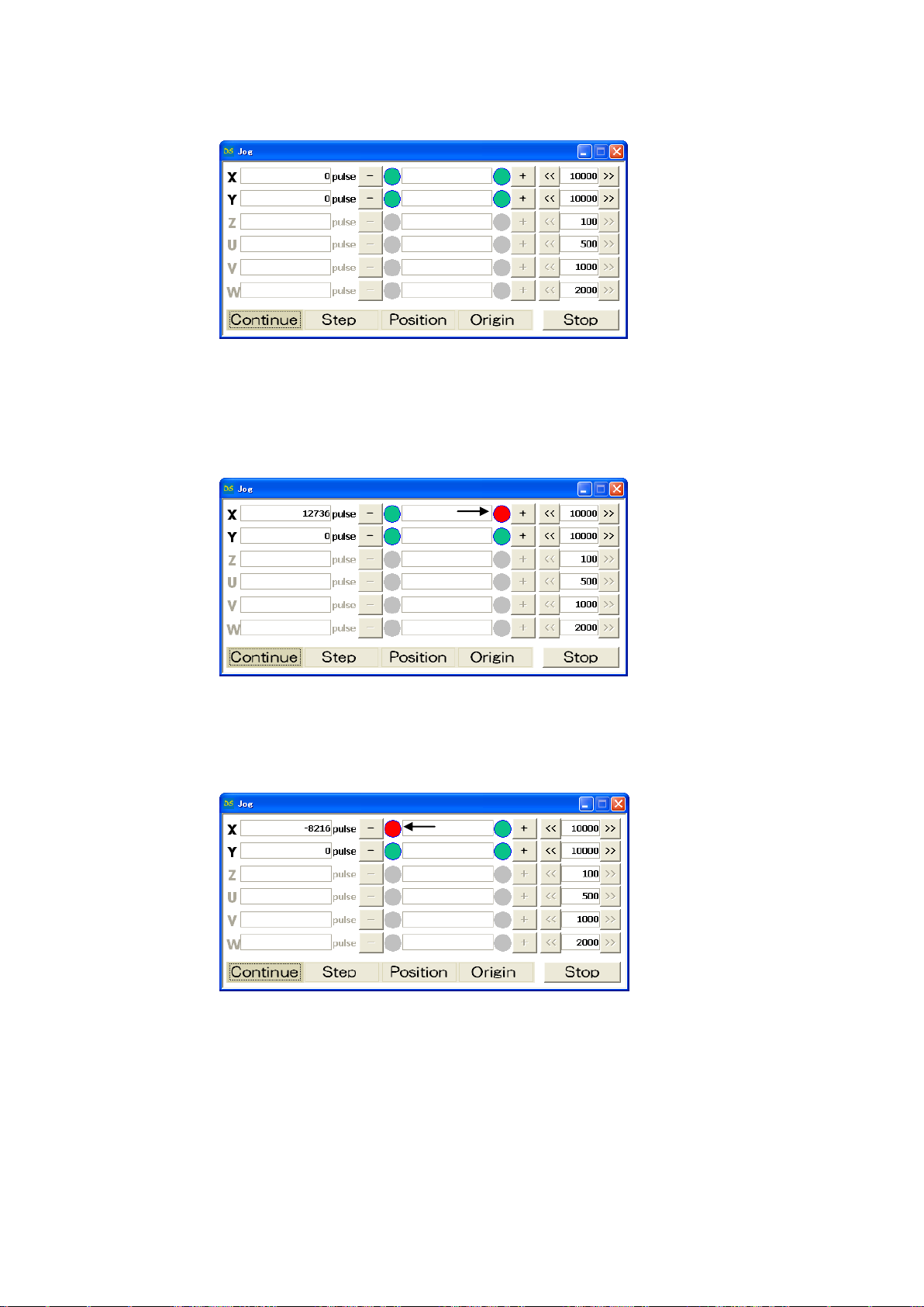
⑥ Click [Contiue]
[+],[-]appear on screen.
⑦ Keep clicking [+] on X axis
X stage moves toward CW direction.
Stage stops when it reachs to CWLS then indicator leftside [+] becomes RED.
⑧ Keep clicking [-] on X axis
X stage moves toward CCW direction.
Stage stops when it reachs to CCWLS then indicator rightside [-] becomes RED.
⑨ Repeat ⑦~⑧ on Y axis.
Page 27
27
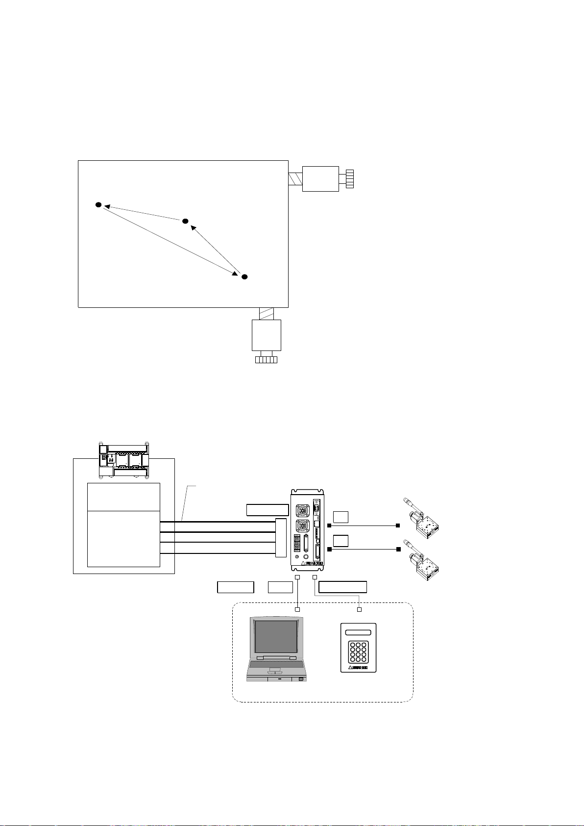
2.2 System architecture
Waiting posi
(50,100)
Working posi
(1000,1500)
Exporting Posi
(2000,3000)
X axis stage
CPU unit
I/O unit
Y axis stage
PLC
XY
DS112
Stepping Motor Controller
DS112
T_BIT0~5
P/T_START
STOP
PRG/TCH
CNT-I/O
I/O cable
DS100-CNT-2
PC
DT100
Handy Terminal
DT100
USB
TERMINAL
X
Y
RS232C or
STEP1 : Moving to waiting position (50,100)
STEP2 : Moving to working position (1000,1500)
STEP3 : Processing on target
STEP4 : Moving to exporting position (2000,3000)
STEP5 : Exporting processig
2.2.1 Movement between each teaching position
Show how to set up position inside memory of DS112 (MISUIMI Type: MSCTL112)and move its
position by PLC.
1) Configuration
※ CNT-I/O shows following signal. READY means Waiting condition of DS112 and X_DRIVE and
Y_DRIVE means both working condition. P/T_RUN means Teaching working and Program
working.
Page 28

28
2) Movement summary
Waiting, working and exporting position memorized inside DS112 as teaching points, 00, 01, 02,
PLC appoints each points then make state move to each points.
① Set up 00 among T_BIT0~5, press P/T_START <STEP1>
② Set up 01 among T_BIT0~5, press P/T_START <STEP2>
③ Wait unitl woring on target is done <STEP3>
④ Set up 02 among T_BIT0~5, press P/T_START <STEP4>
⑤ Wait until exporting is done <STEP5>
3) Connect
Connect to DS112
PC is used when setting or editing teaching point
① Connect USB to PC USB port
(Connect RS232C to PC when using RS232C)
② Connect handy terminal to DS112
③ Connect X axis motor connector to X stage
④ Connect Y axia motor connector to Y stage
⑤ Connect control I/O connector to PLC I/O unit
On control I/O,
T_BIT0~5:Appoint teaching point
P/T_START:Signal to move to teaching point
STOP:Stop signal for all axes
PRG/TCH:program mode / teaching point mode
※ T_BIT0~2:combined use for program selection
Page 29
29
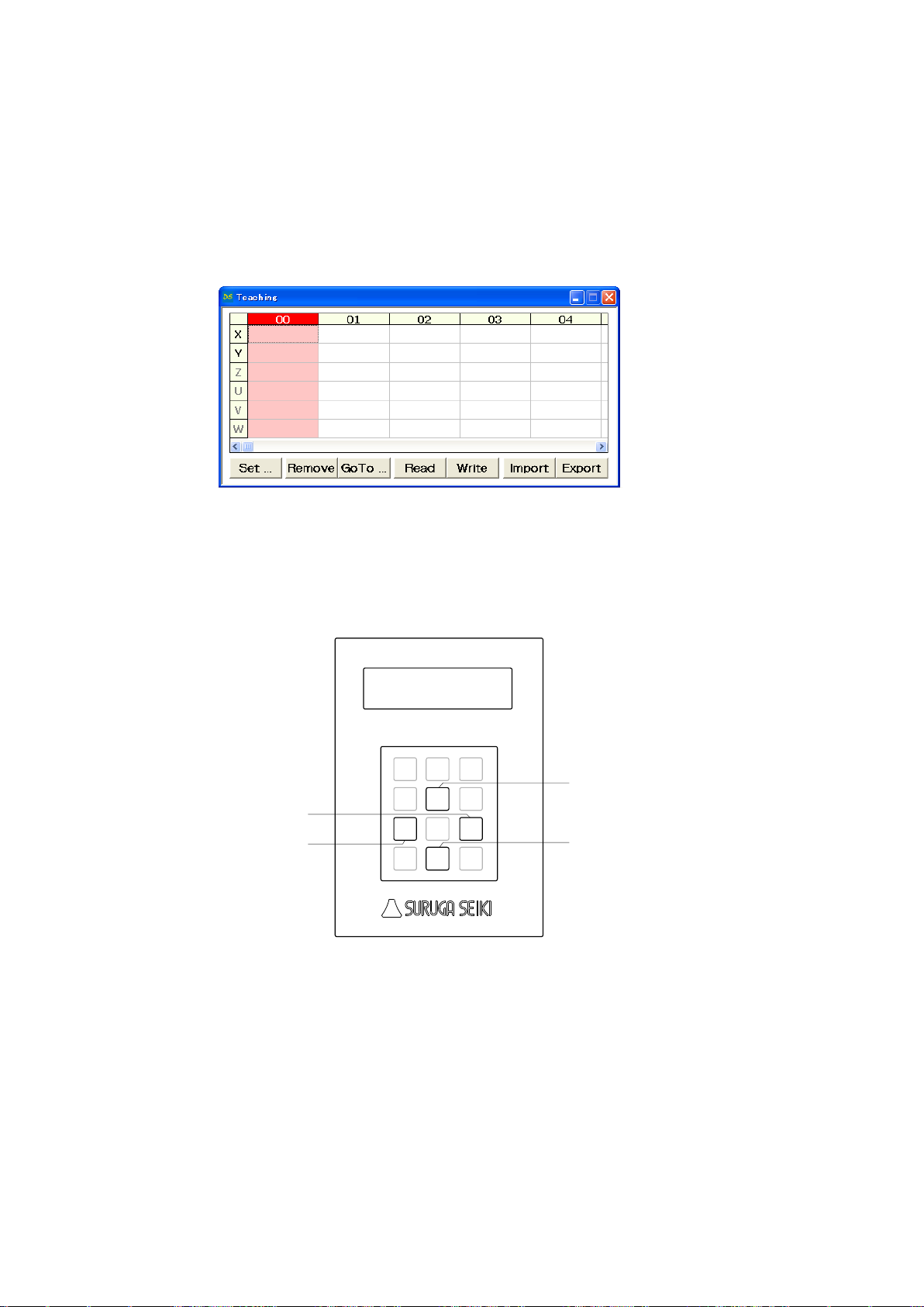
4) Memory of teaching point
Jog
7
Menu8Set
9
SPD
4
↑
5
POS
6
←1Link
2
→
3
Stop
0
/ESC
DT100
Handy Terminal
↓
.-
Enter
X stage CCW direction
X stage CW direction
Y stage CCW direction
Y stage CW direction
Memorizing teaching point inside DS112
① Start DSCONTROL-WIN
② Select [Teaching] on main menu in DSCONTROL-WIN.
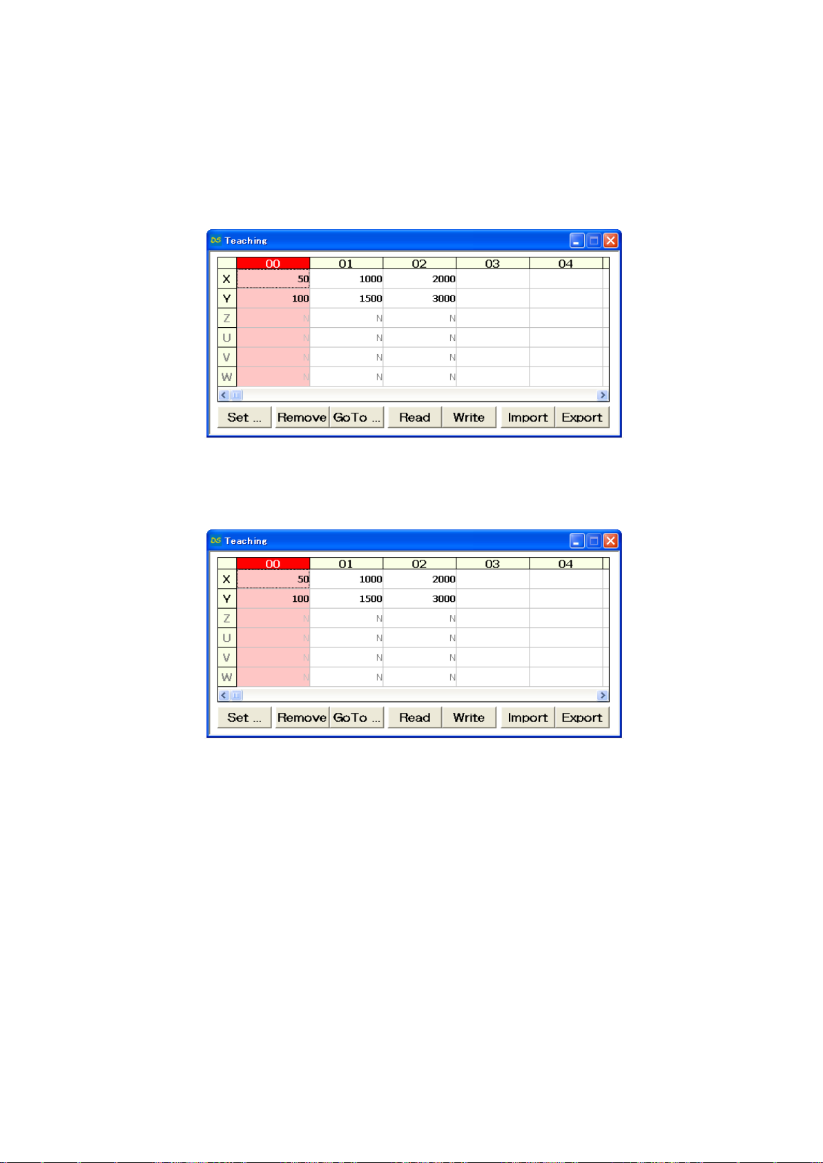
Screen below appears.
③ Push direction key on handy terminal unitl stage moves to specific positon.
Page 30
30
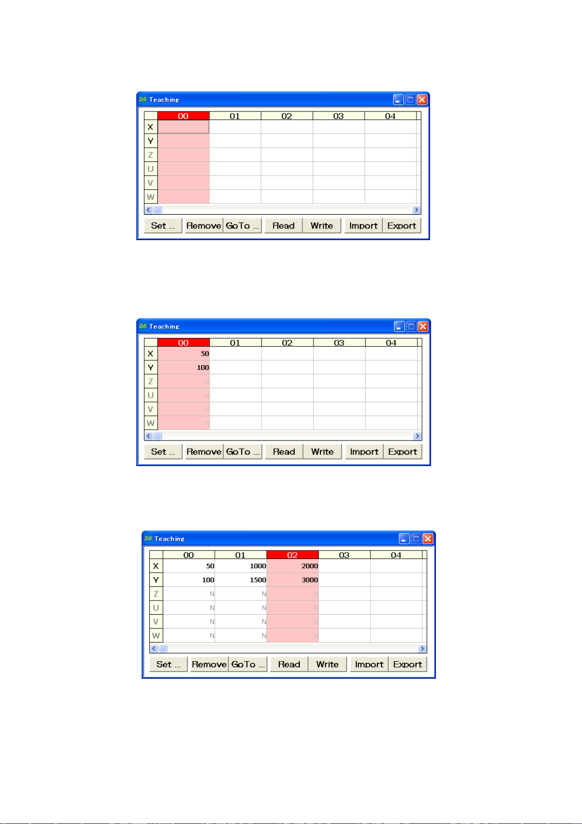
④ Click [00] CELL on the teacing screen
00 CELL gets to be Red.
⑤ Click [Set]
Current stage position as 00 is memorized to DS112.
⑥ Repeat ③~⑤ so memorize 01 as working position and 02 as exporting position to DS112.
Page 31
31
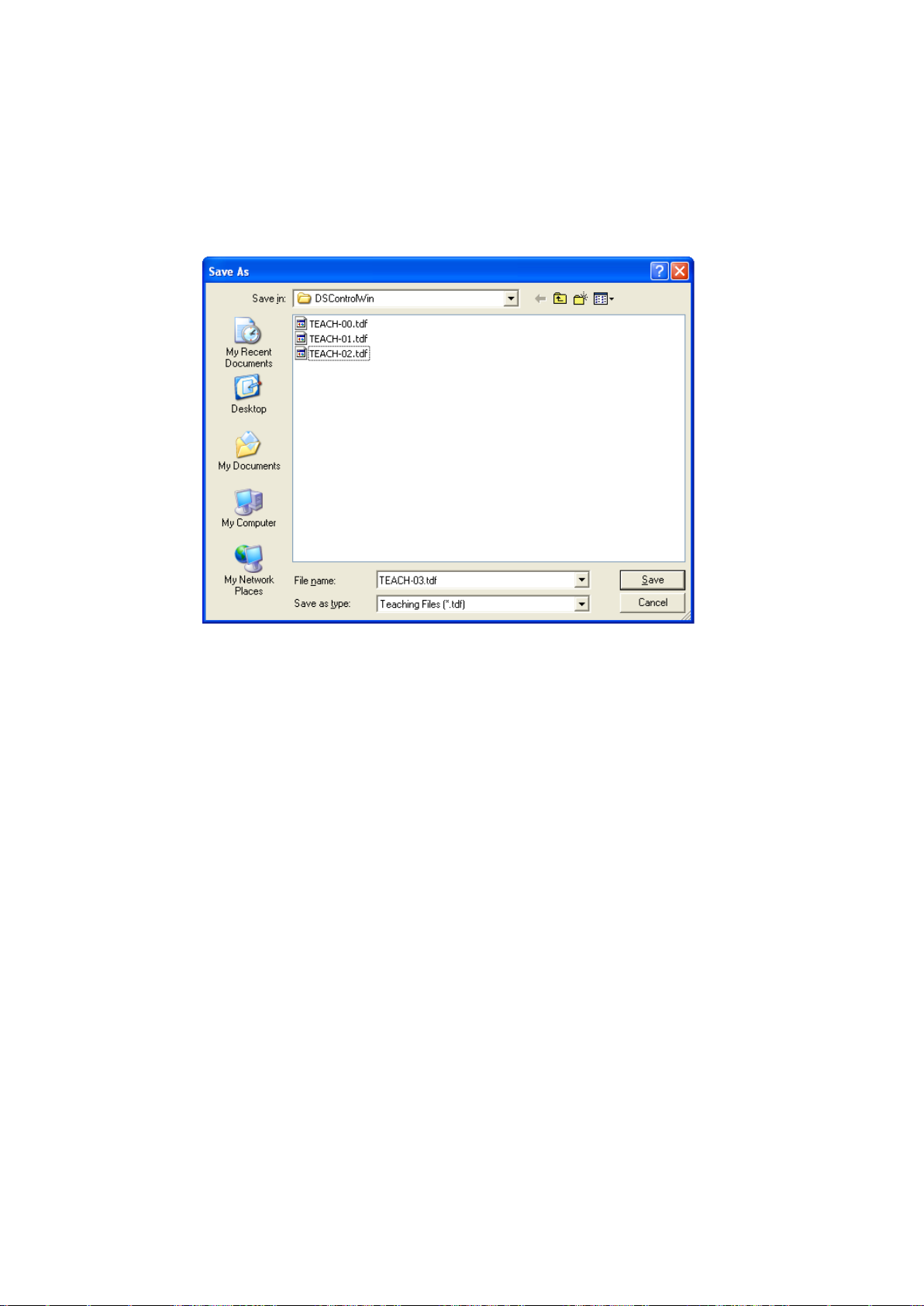
5) Save teaching file
Teaching points memorized are saved as teaching file in PC.
① Click [Save]
Save As appears on screen.
② Clcik [Save] after you determine [Save location] and [File name]
Teaching file is saved in PC.
※ tdf is added to your file name as extension.
Page 32
32
6) Operation check
Checking movememt to the memorized position.
① No interference affects stage movement.
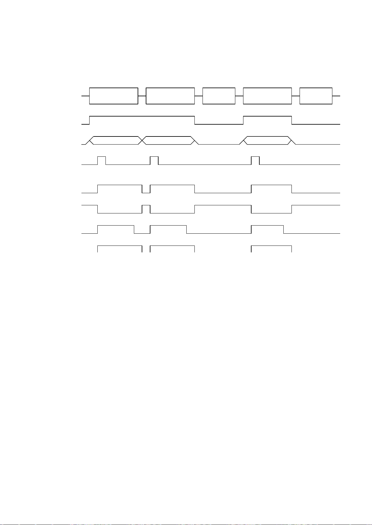
② Click [00] CELL on teaching screen.
00 CELL gets to be Red.
③ Click [Go to].
Stage moves to teaching point [00] (Waiting point).
④ Repeat ②~③ and check same operation at teaching point [01] working position as well as
[02] exporting position.
Page 33
33
7) Execution of movement
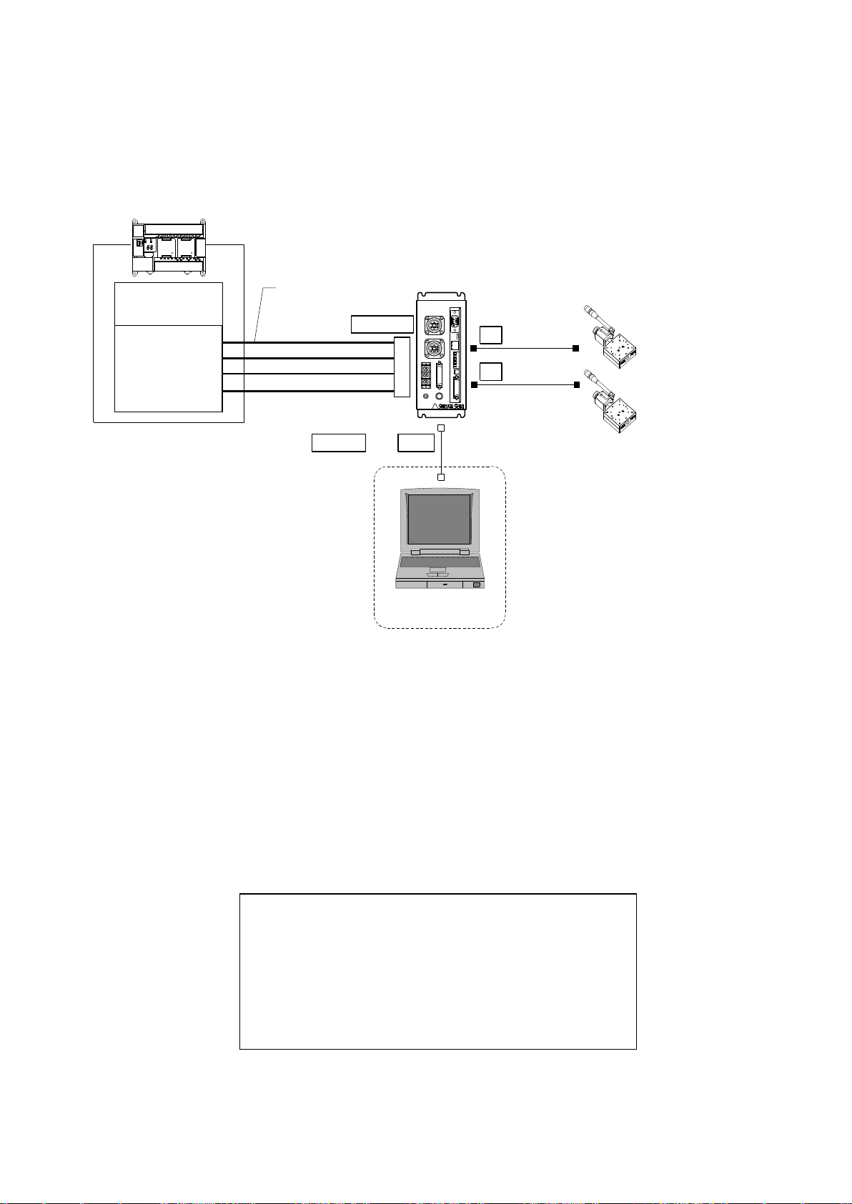
Timing chart
PRG/TCH
T_BIT5-0
P/T_START
Function
00 01 02
Move to wait posi Move to Target Working Move to expt posi Working
P/T_RUN
READY
X_DRIVE
Y_DRIVE
Execute movement to teaching position by PLC.
※ All stages stop when making signal [STOP] [ON]
Page 34
34
2.2.2 Easy return to origin position
CPU unit
I/O unit
X axis stage
Y axis stage
PLC
XY
DS112
Stepping Motor Controller
DS112
P_BIT0~2
P/T_START
STOP
PRG/TCH
CNT-I/O
I/O cable
DS100-CNT-2
X
Y
PC
USBRS232C or
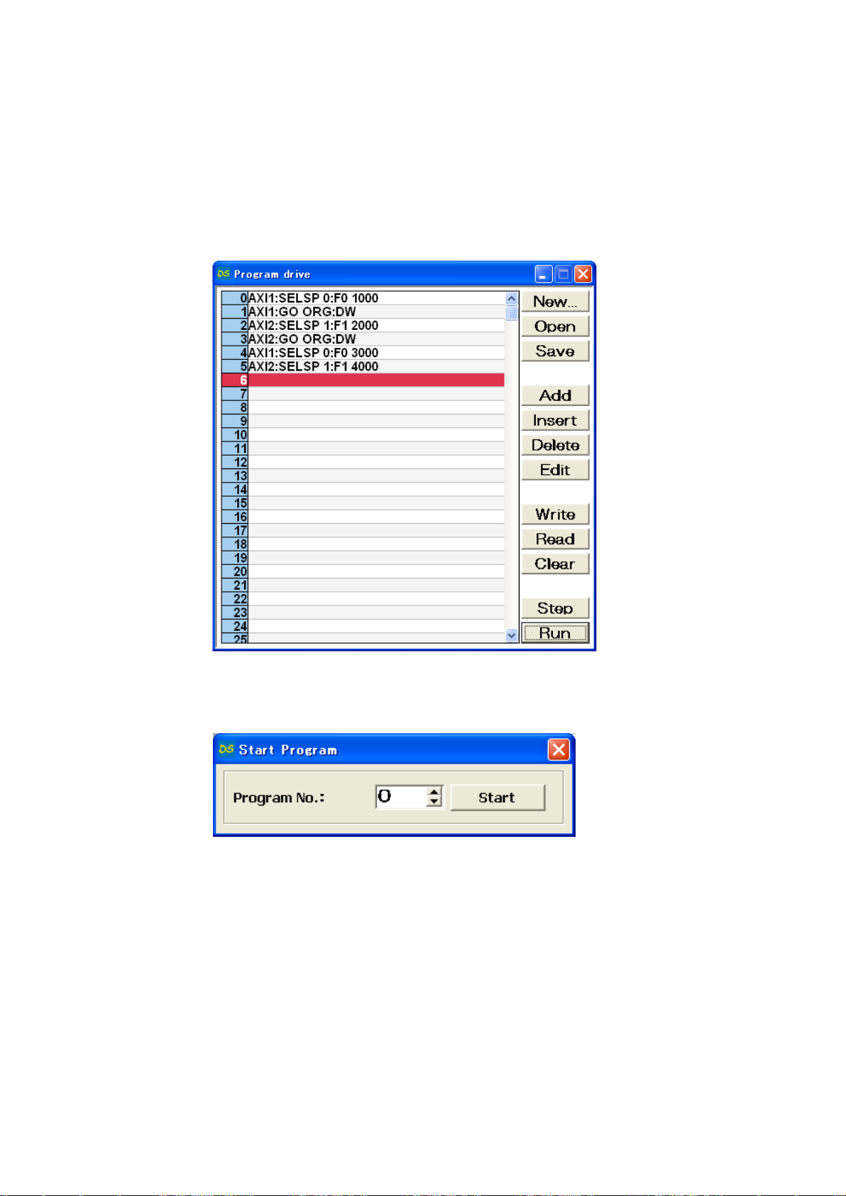
Program #0
① Speed adjustment on X axis origin return movement
② [Origin] return on X axis
③ Speed adjustment on Y axis origin return movement
④ [Origin] return on Y axis
⑤ Speed adjustment on X axis movement
⑥ Speed adjustment on Y axis movement
Shows how to set [Origin] program in DS112 and execute [Origin return] by PLC.
1) Configuration
※ CNT-I/O continuously output READY is stand-by condition of DS112, X_DRIVE is X axis
working condition, Y_DRIVE is Y axis working condition and P/T_RUN means teaching point and
program are in action.
2) Movement summary
Setting up [Origin] program at program #0 in DS112 and [Origin] program starts by using PLC.
① Set 0 among P_BIT0~2 and make P/T_START ON (Program #0 starts).
Page 35
35
3) Connection
Connection of DS112
PC (DSCONTROL-WIN) is connected only when creating or editing program.
① Connect USB connector to USB port in PC
(Connect RS232C to PC when using RS232C)
② Connect X axis stage connector to X axis stage
③ Connect Y axis stage connector to Y axis stage
④ Connect control I/O connector to I/O unit in PLC
On control I/O,
P_BIT0~2:Select program #
P/T_START:Signal of movement to teaching point
STOP:Stop signal for all axes
PRG/TCH:Select mode (Start program / movement to teaching point)
※ P_BIT0~2: combined use for teaching point selection
4) Creating program
Creating [Origin return] of two axes.
① Start DSCONTROL-WIN
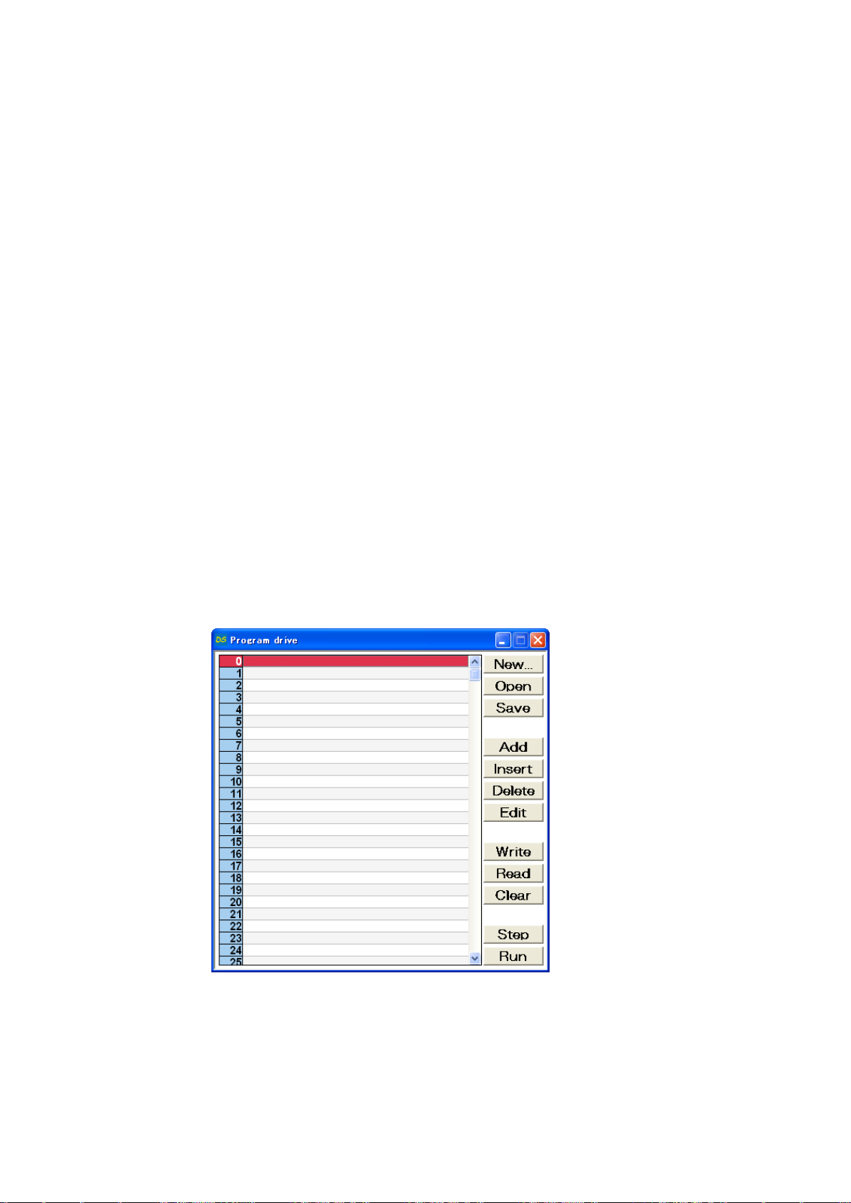
② Click [Action]→[Program drive] on main menu.
Page 36
36
③ Click [Add]
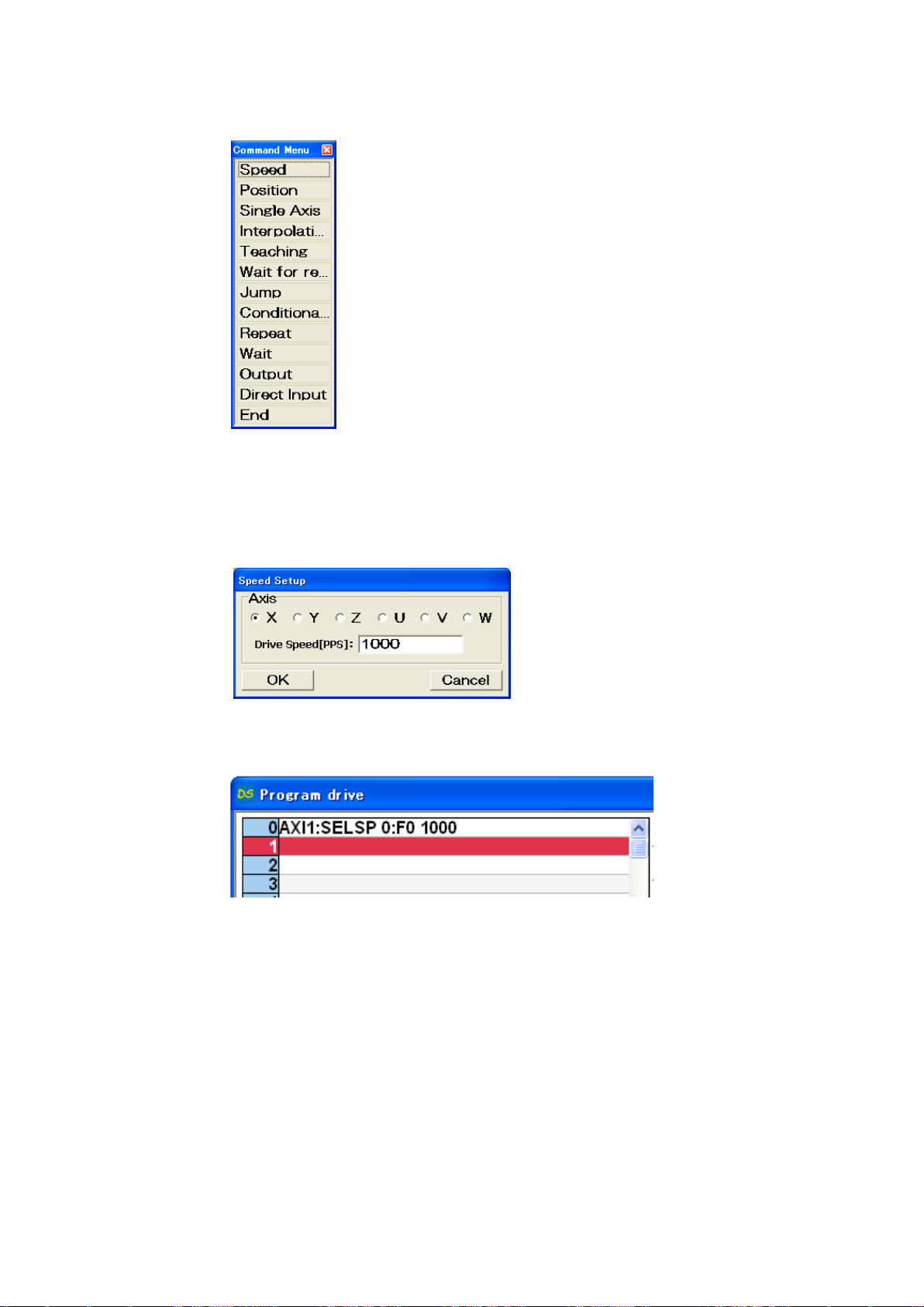
The display below appears on display.
④ Click [Speed] on command menu
“Speed Setup” appears on display.
⑤ Check axis X and input speed value then click [OK].
Command appears on the program drive screen.
⑥ Click [Add] on Program drive
Drive menu appears on display.
Page 37
37
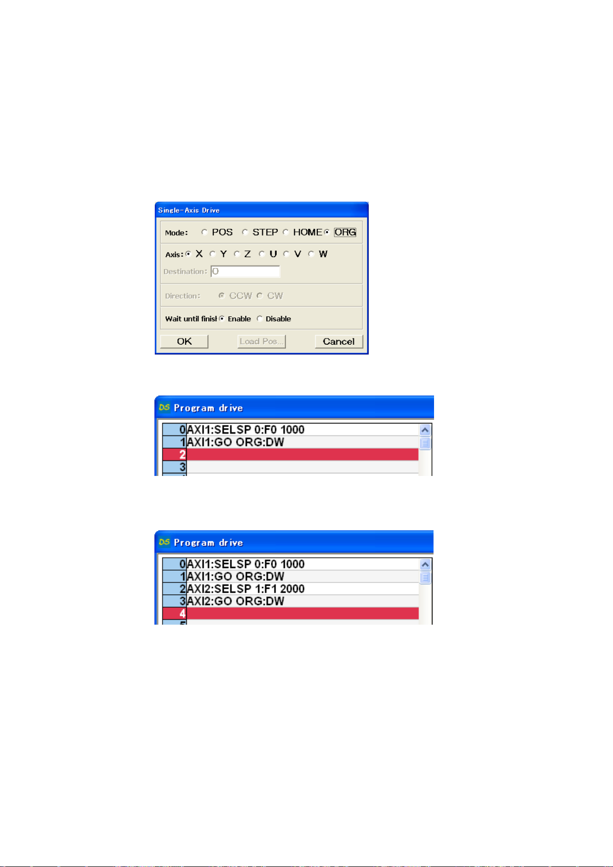
⑦ Click [Single Axis Drive]
Single Axis Drive appears on display.
⑧ Single Axis Drive display
[Mode] = “ORG”
[Axis] = “X”
[Wait until finish] = “Enable”
Click [OK]
[Origin] of X axis command appears on the first line.
⑨ Repeat ③~⑧ for Y axis
⑩ Click [Add]
Drive command menu appears on display.
Page 38
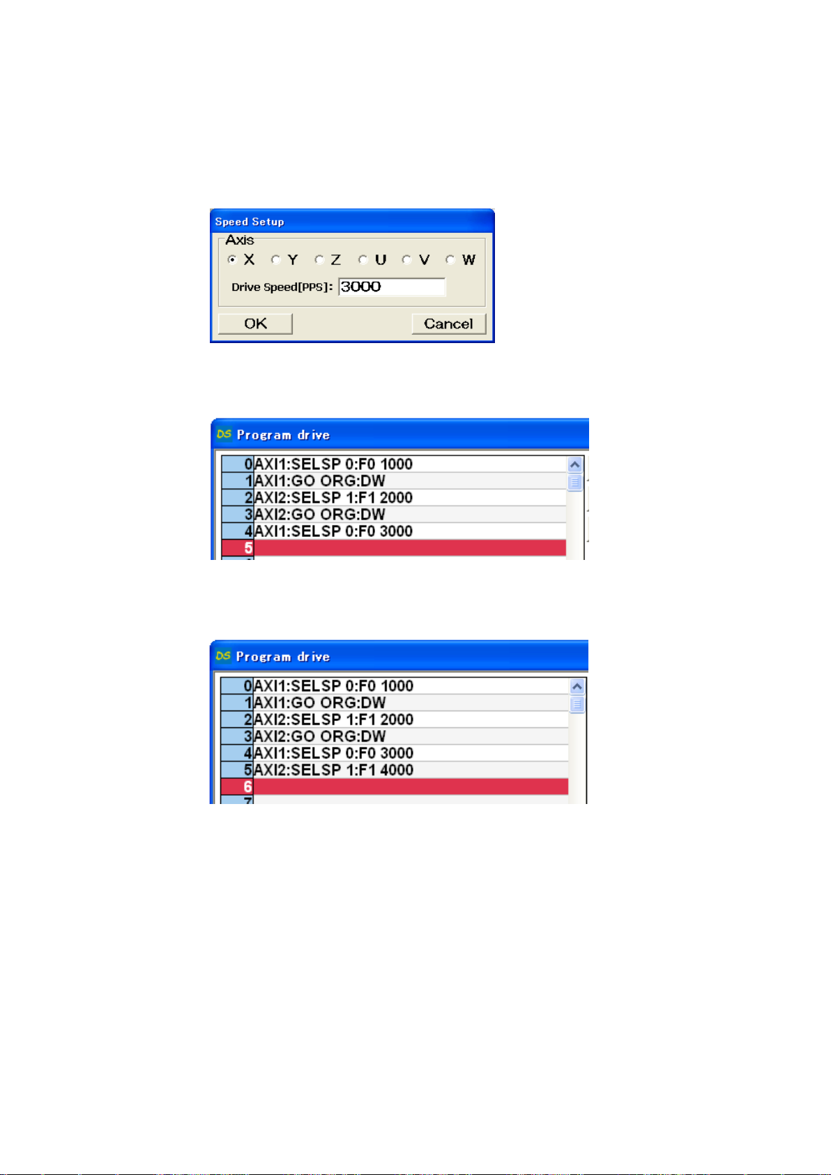
38
⑪ Click [Speed]
Speed Setup display appears display.
⑫ Check [Axis] X and input drive speed value then click [OK].
Speed command appears on the fourth line.
⑬ Repeat ⑩~⑫ to set up Y axis speed.
Page 39
39
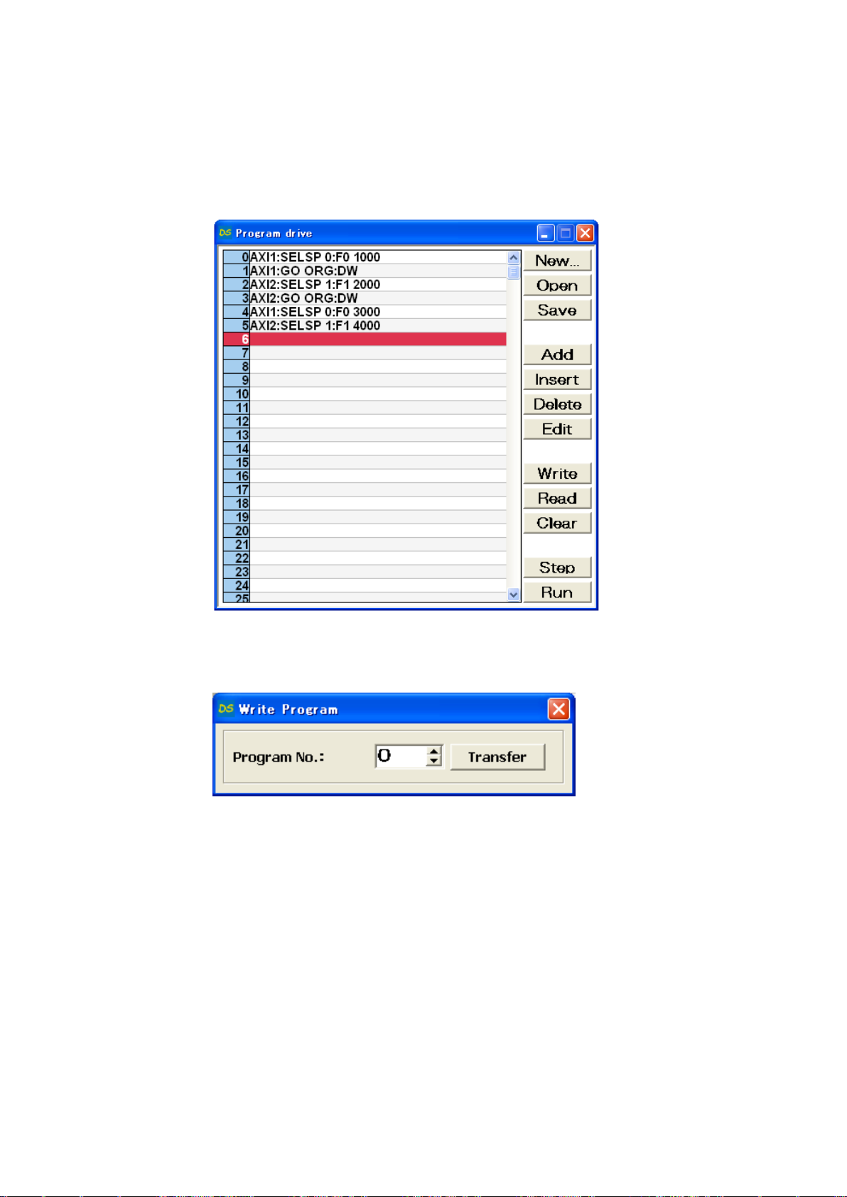
5) Writing program
Writing program to DS112
① Click [Write]
Write Program appears on display.
② Select [0] then click [Transfer]
Program is forwarded to Program#0.
Page 40
40
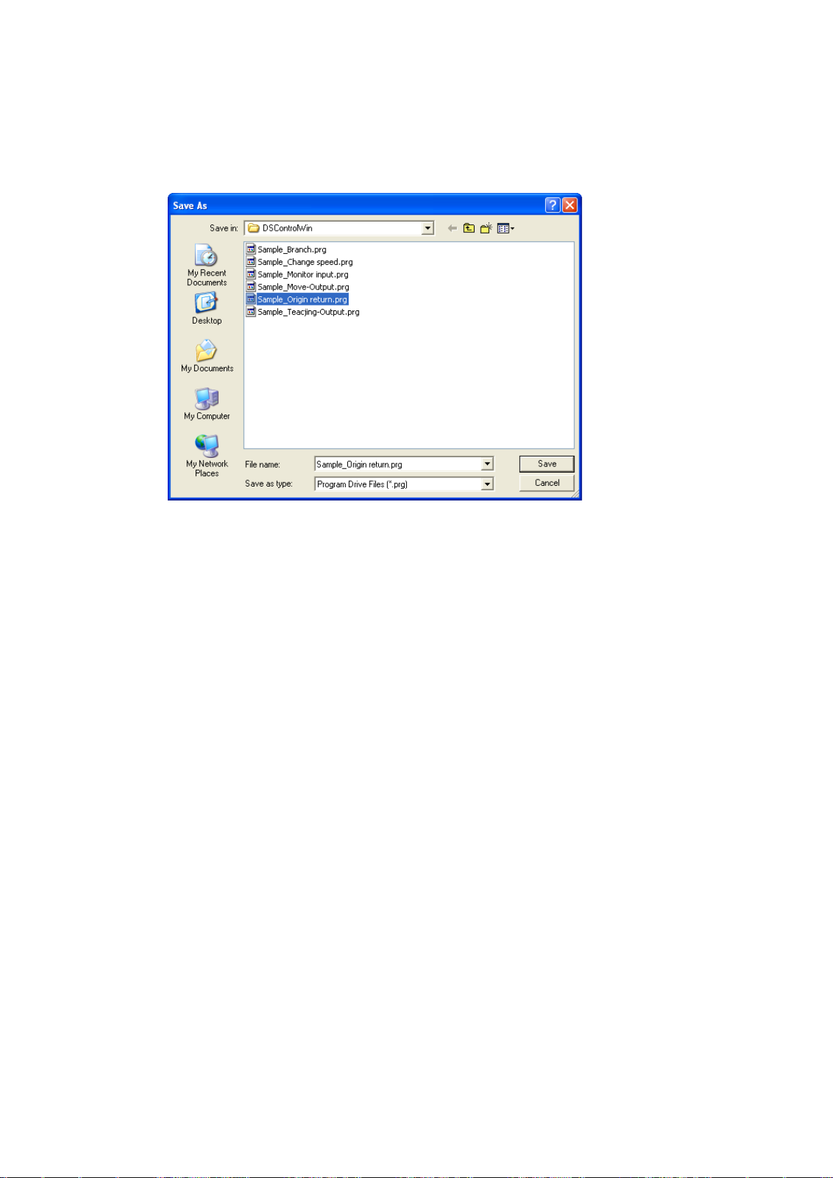
6) Save program
Save program at PC program drive file.
① Click [Save] on program drive display
The display below appears on display.
② Select [location] and [file name] then click [Save].
Program is saved as Program drive file.
※ prg is automatically added as extension.
Page 41
41
7) Operation check
Checking movement to origin return.
① No interference affects stage movement.
② Click [Start]
Start Program appears on display.
③ Select program [0] then click [Start].
Page 42
42
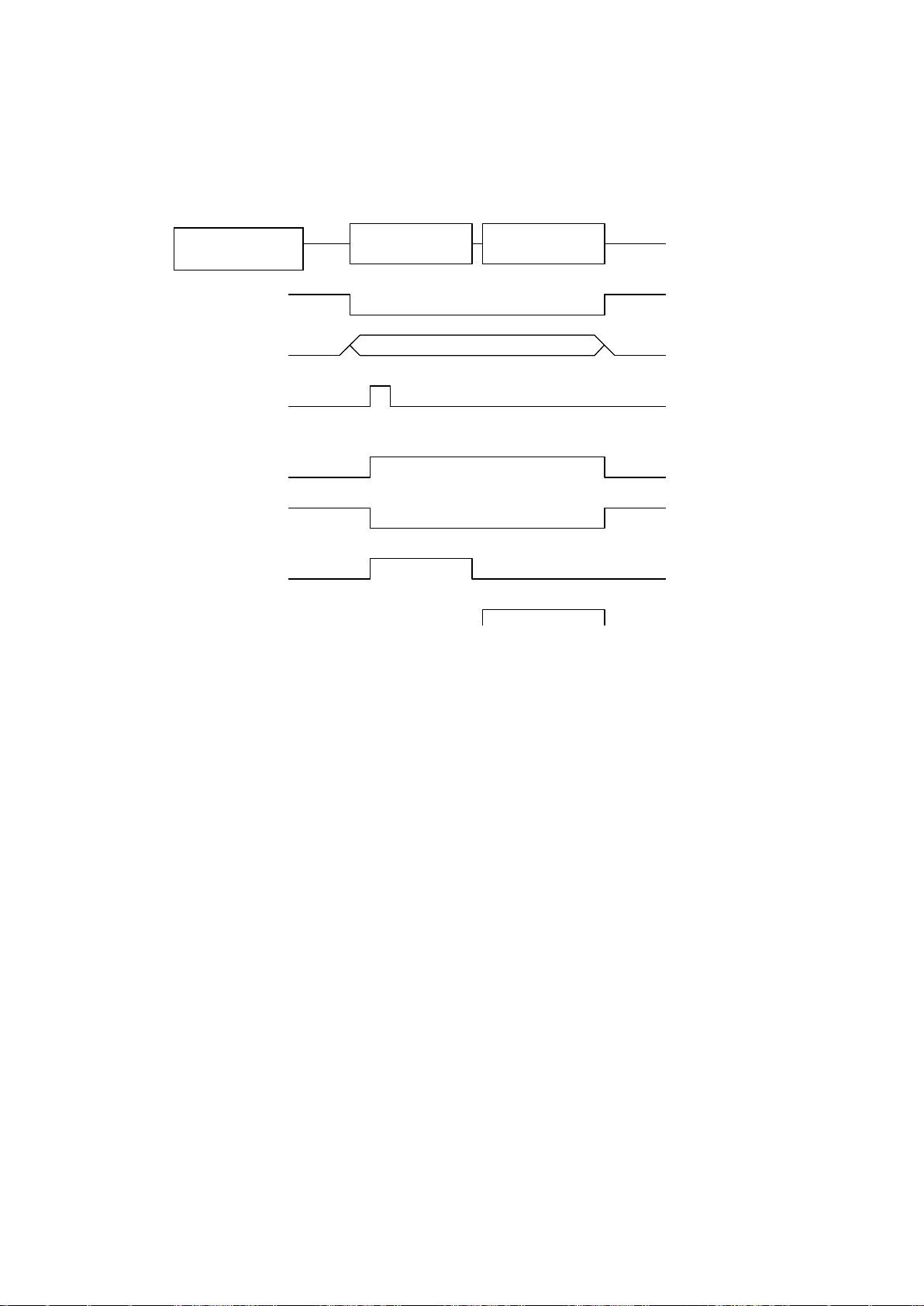
8) Practice of movement
Timing chart
PRG/TCH
P_BIT2-0
P/T_START
動作
0
X axis origin
return
Y axis origin
return
P/T_RUN
READY
X_DRIVE
Y_DRIVE
Function
Movement to [Origin] position by PLC.
※ All stages stop when [STOP] button
Page 43
43
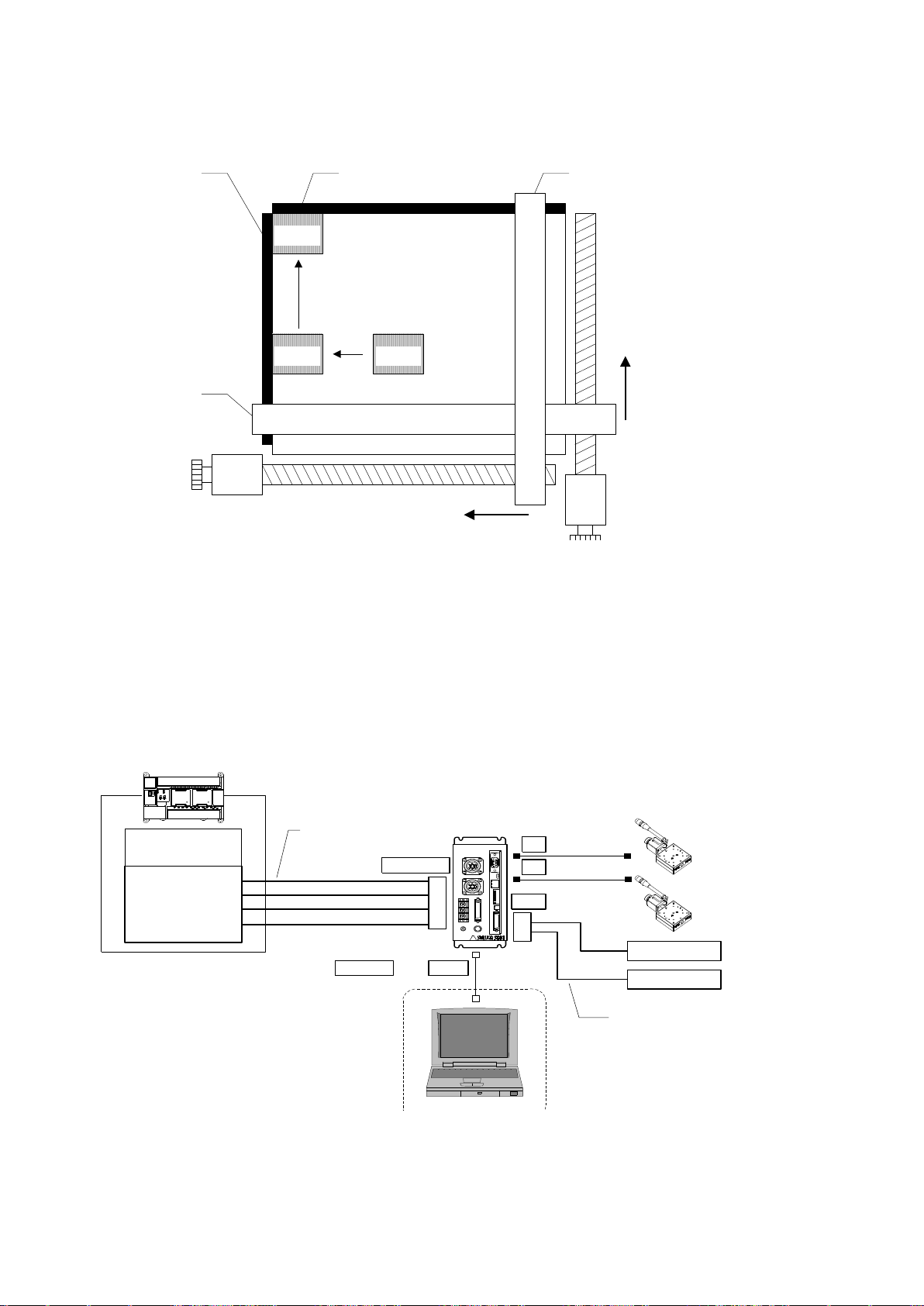
2.2.3 Control by external signal
CPU unit
I/O unit
X guide
Y guide
PLC
XY
DS112
Stepping Motor Controller
DS112
P_BIT0~2
P/T_START
STOP
PRG/TCH
CNT-I/O
CNT-I/O cable
DS100-CNT-2
I/O
X sensor
Y sensor
In00
In01
General I/O cable
DS100-IO-2
USBRS232C or
X
Y
STEP1 : Set both X and Y stages at starting position (50,100)
STEP2 : Move X stage by 10pulses then stop X stage when target reach X sensor
STEP3 : Move Y stage by 10pulses then stop Y stage when target reach Y sensor
X motor
Y motor
workwork
work
X sensor Y sensor X guide
Y guide
Shows how to stop stage by external signal that DS112 outputs.
1) Configuration
※CNT-I/O continuously output READY is stand-by condition of DS112, X_DRIVE is X axis working
condition, Y_DRIVE is Y axis working condition and P/T_RUN means teaching point and program are in
action.
Page 44
44
2) Operation summary
Program #1
① Setting up address speed on both X and Y axes
② Movement of X and Y axes to work starting point <STEP1>
③ Move X axis to CW direction by 10 pulse
④ Repeat ③~④ until target reaches X sensor <STEP2>
⑤ Move Y axis to CW direction by 10 pulse
⑥ Repeat ⑤~⑥ until target reaches Y sensor <STEP3>
Setting up [Detecting sensor program] at program #1 in DS112 then executing movement by
PLC addressing program #1.
① Settting up 1 among P_BIT0~2 then press [ON] on P/T_START (Executing program #1).
3) Connection
Connection of DS112.
PC (DSCONTROL-WIN) is connected only when creating or editing program.
① Connect USB connector to USB port in PC
(Connect RS232C to PC when using RS232C)
② Connect X axis stage connector to X axis stage
③ Connect Y axis stage connector to Y axis stage
④ Connect control I/Oconnector to I/O unit in PLC
On control I/O,
P_BIT0~2:Select program #
P/T_START:Signal of movement to program
STOP:Stop signal for all axes
PRG/TCH:Select mode (Start program / movement to teaching point)
⑤ Connect X sensor and Y sensor to general I/O.
Assign X axis sensor output to In00, and Y axis sensor output to In01.
Page 45
45
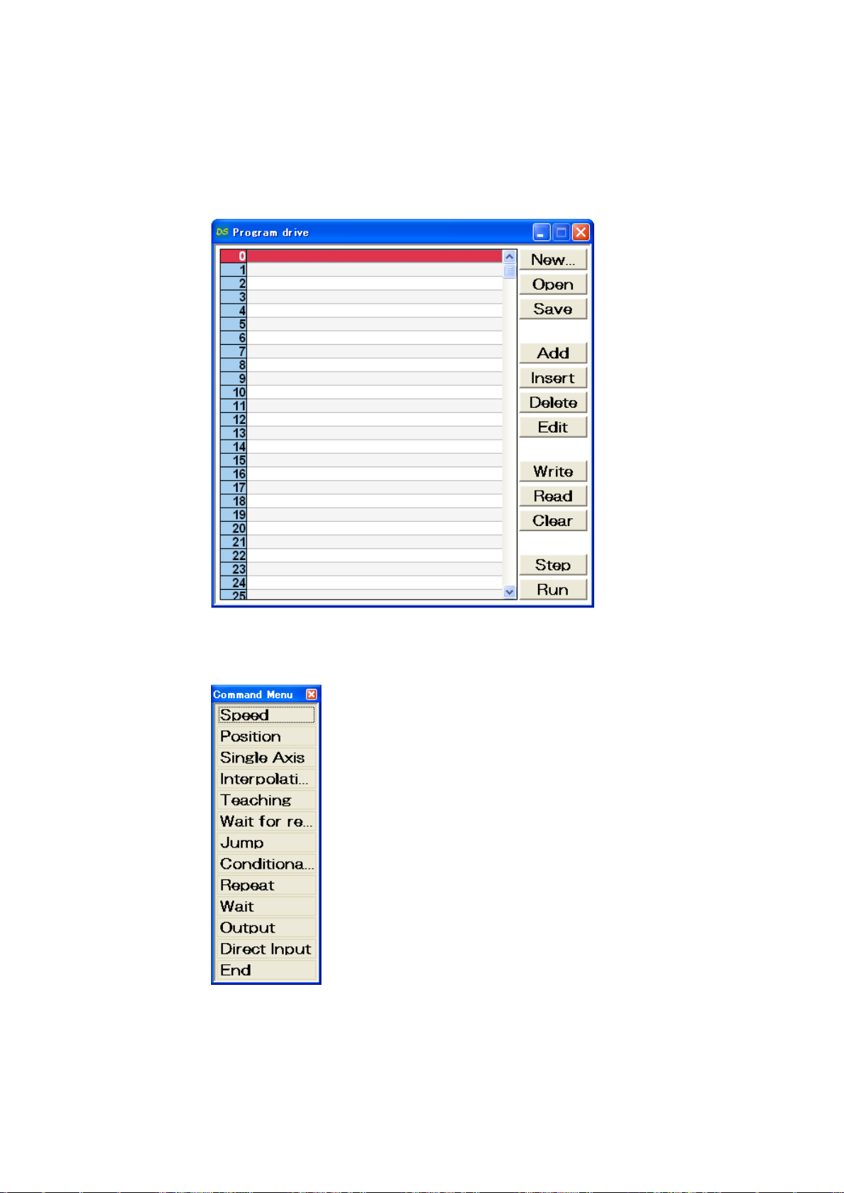
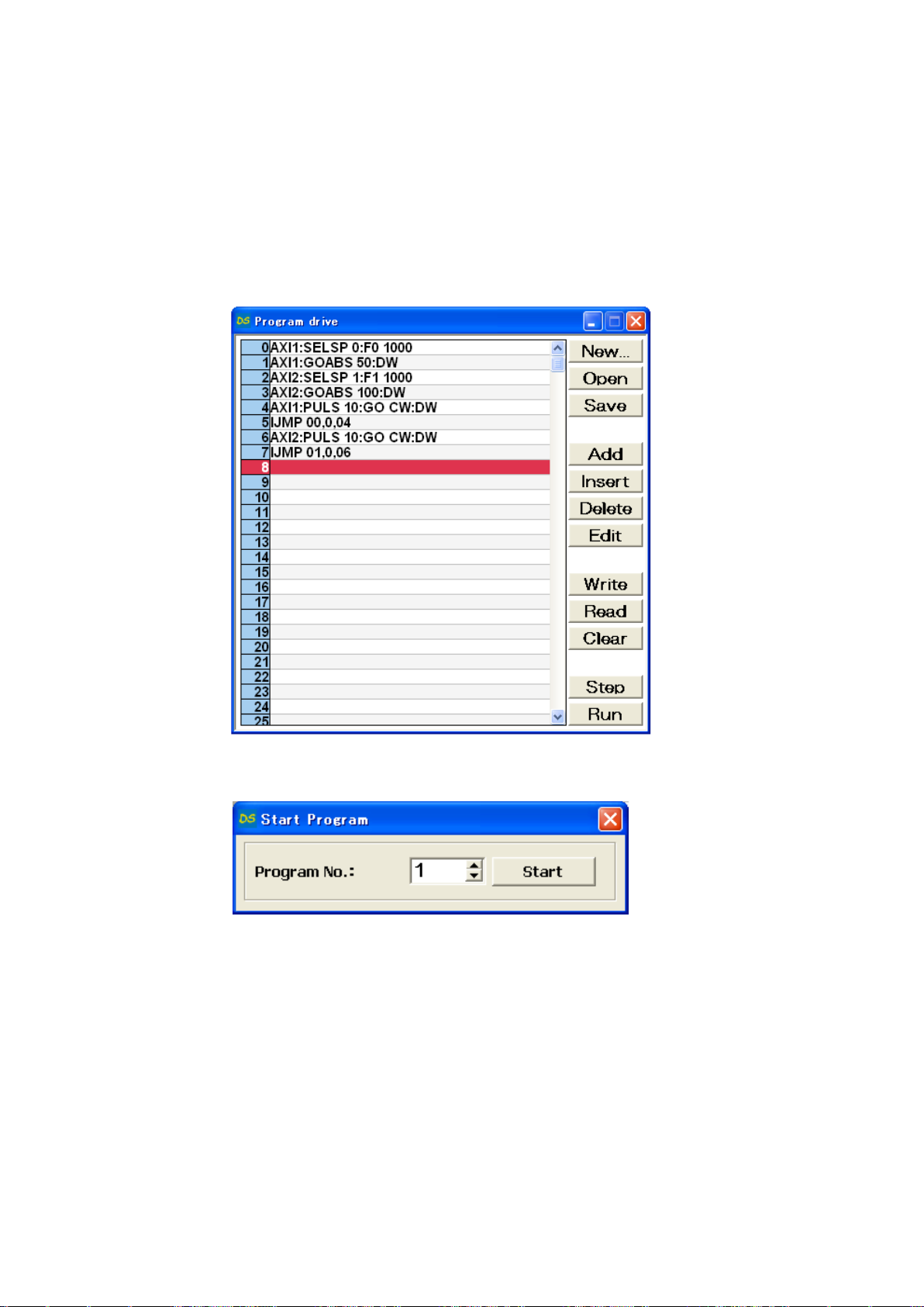
4) Creating program
Creating the program that stopping axis in response to external sensor.
① Starts DSCONTROL-WIN.
② Click [Action]→[Program drive] on main menu.
③ Click [Add]
Command menu appears on display.
Page 46
46
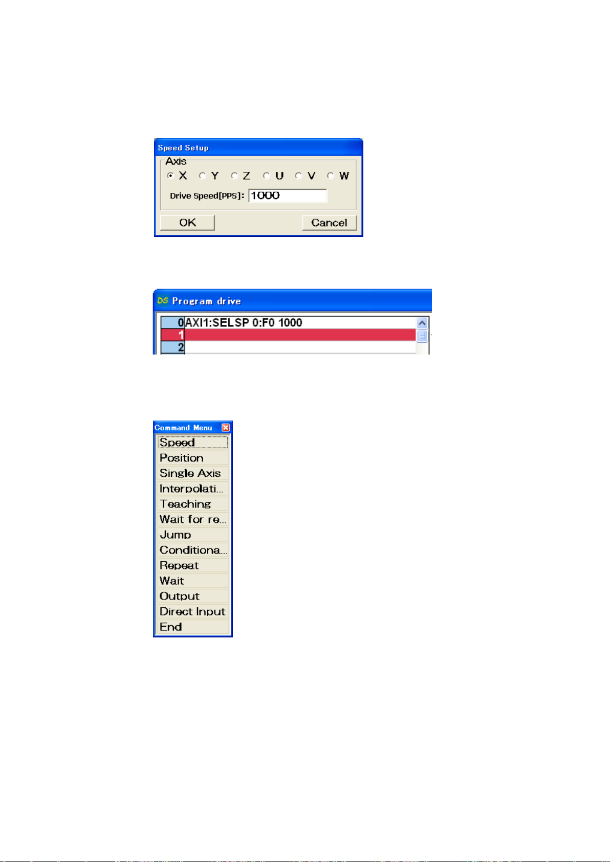
④ Click [Speed] on command menu.
⑤ Check Axis X and input speed value then click.
Drive speed value appears on the line [0] on program drive display.
⑥ Click [Add] on.
Command menu appears on display.
Page 47
47
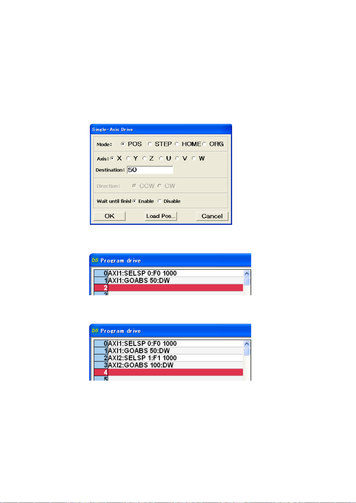
⑦ Click [Single Axis]
Single Axis Drive appears on display..
⑧ Single-Axis Drive.
[Mode] = “POS”
[Axis] = “X”
[Destination] = “50”
[Waiiting until finish] = “Enable”
Click [OK]
Movement command on X axis appears.
⑨ Repeat ③~⑧ then input speed drive and movement command on Y axis.
⑩ Click [Add] on Drive command menu.
Drive command menu appears.
Page 48
48
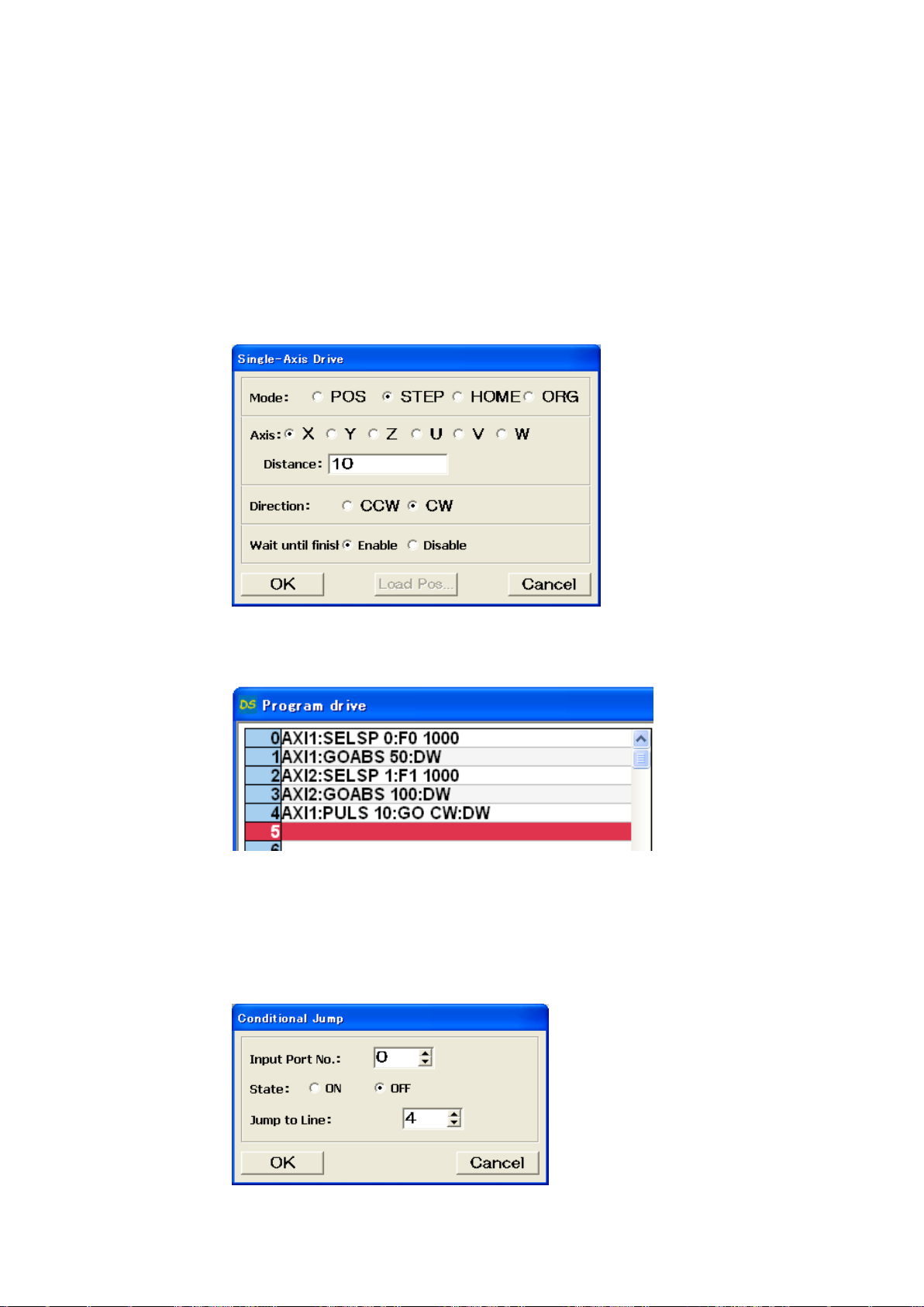
⑪ Click [Single Axis].
Single-Axis Drive appears on screen.
⑫ Single-Axis Drive
[Mode] = “STEP”
[Axis] = “X”
[Diistance] = “10”
[Direction] = “CW”
[Wait until finish] = “Enable”
Click [OK].
Program command on X axis appears on fourth line.
⑬ Click [Add] on Program drive
Drive command menu appears.
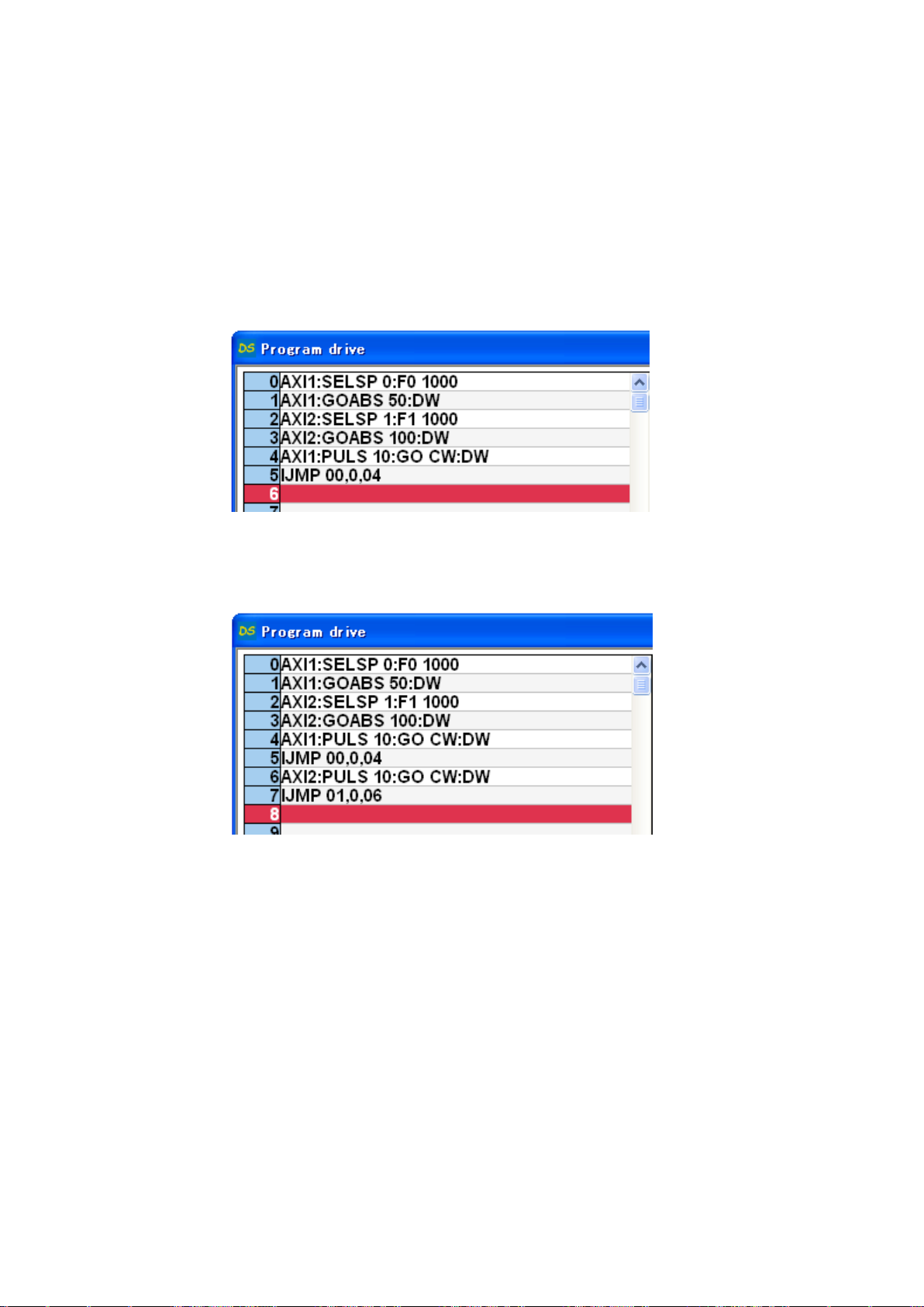
⑭ Click [Conditional Jump] on Drive command menu
Conditional Jump appears.
Page 49
49
⑮ Input [0] at Input Port No, [OFF] at State and [4] at jump to Line then click [OK].
Repeat Command on fourth line while State of input0 is [OFF] .
Conditional Jump command appears on fifth line on Program Command display.
※ On Conditional jump is set up, Command on fourth line is repeated while State of input0 is
[OFF].
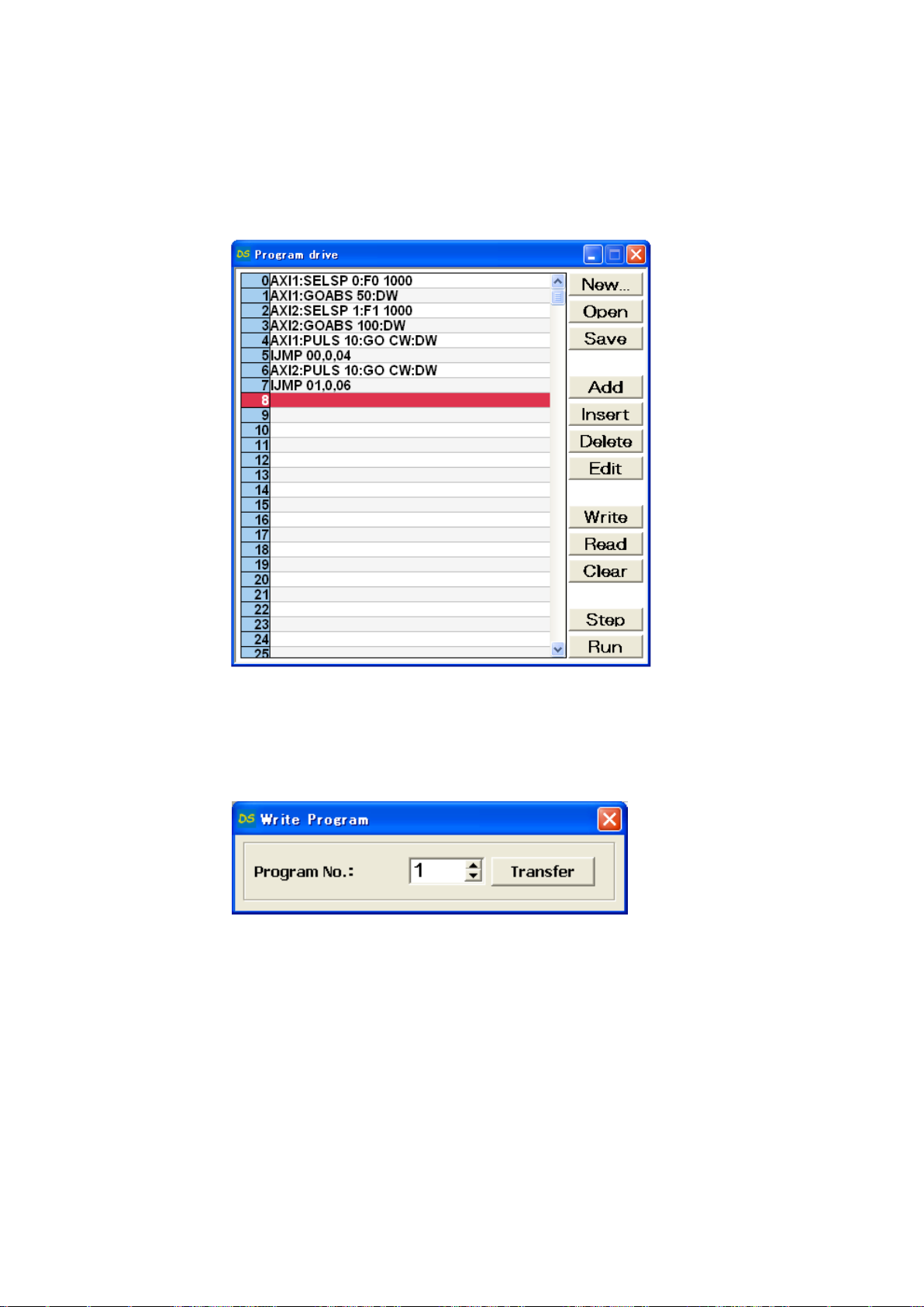
⑯ Repeat ⑩~⑮ to input movement command and conditional jump command to Y axis.
Page 50
50
5) Writing Program
Writing program in DS112.
① Click [Write] on Program Drive.
Write Program appears on display.
② Select Program #1 then click [Transfer].
Program is forwarded to Program #1.
Page 51
51
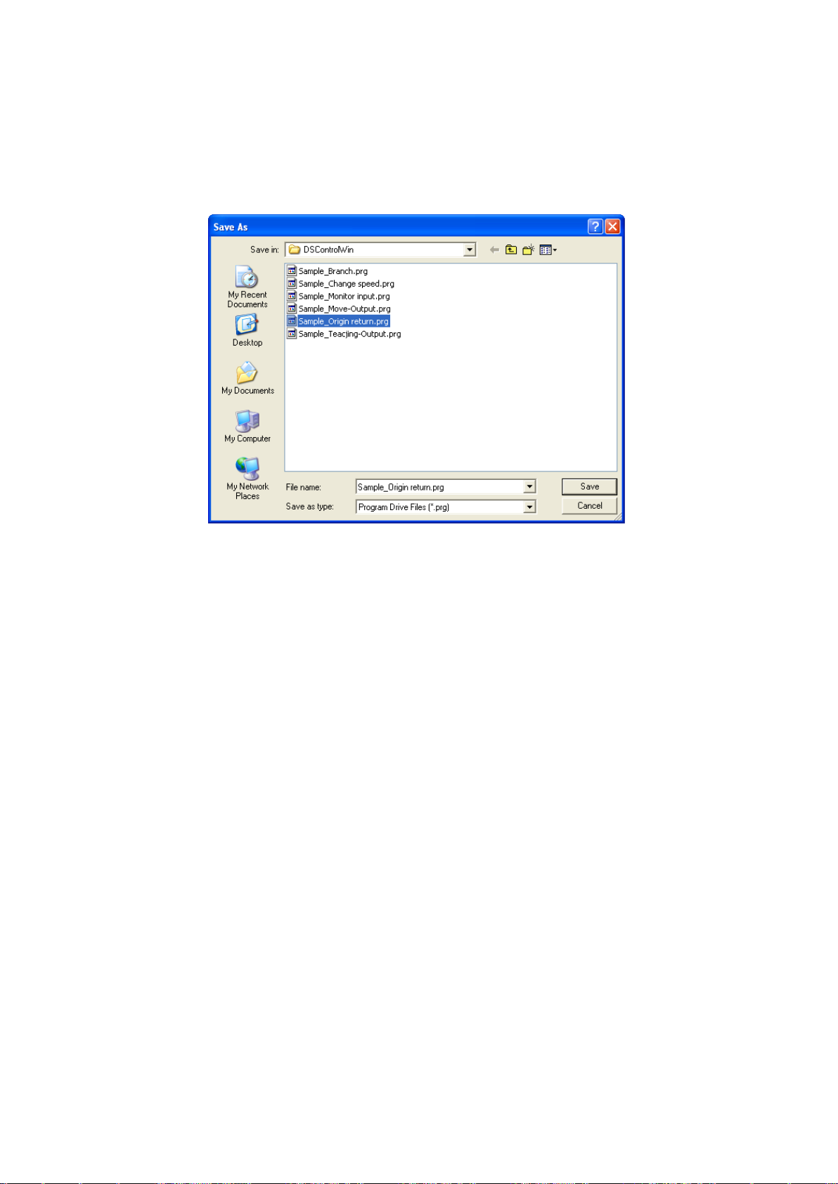
6) Save Program
Save Program in Program drive file.
① Click [Save] on Program drive display.
Saving display of Program drive appears.
② Confirm save location and its name then click [Save].
Program is saved in Program drive.
※ .prg is automatically added as extension.
Page 52
52
7) Operation check
Checking stage movement by external signal.
① No interference affects stage movement.
② Click [Start].
Start Program appears on display.
③ Select 1 at Program No.: then click [Start].
Page 53
53
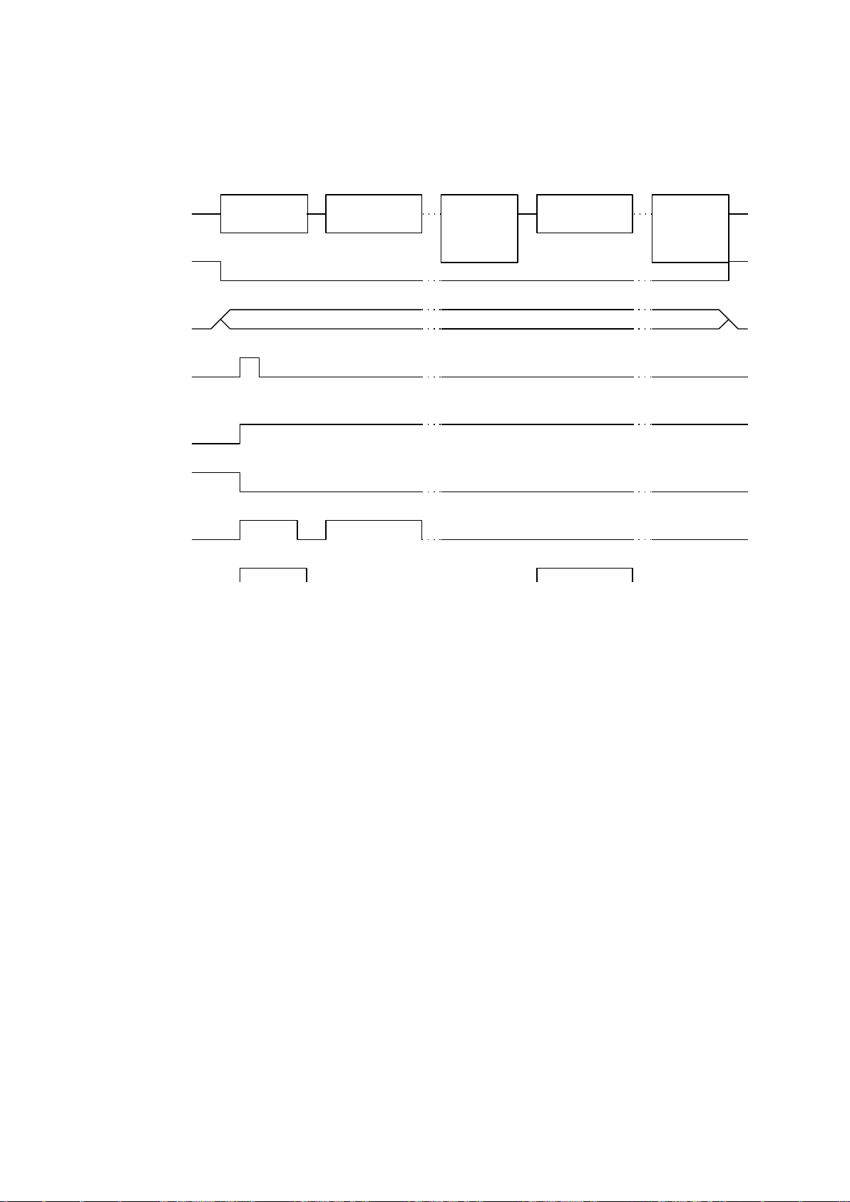
8) Operating
Timing chart
Move to the
start position
Move 10pulse
to X axis CW
X axis
sensor
Output
detector
Move 10pulse
to Y axis CW
Y axis
sensor
state
detection
PRG/TCH
P_BIT2-0
P/T_START
Operating
1
P/T_RUN
READY
X_DRIVE
Stop the axes due to input external signal.
※ All stages will be stopped when input the “STOP” signal.
Page 54
54
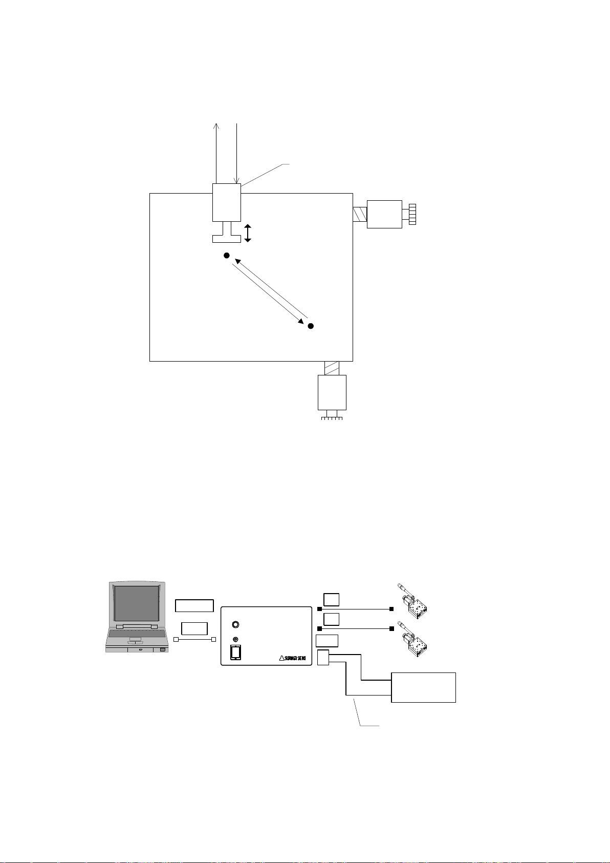
2.2.4 External device control with generalI/O.
Waiting
position
(50,100)
Action point
(1000,1500)
Actuator
Input the signal to start
pressure operating.
Completed pressure operating,
output the completed pressure
operating signal .
Pressure
operating
Out00In00
Press-in
operating
Start signal
Press-in
operating
Completed
signal
X axis stage
Y axis stage
I/O
Actuator
Out00
In00
General I/O cable
DS100-IO-2
Computer
DS102
Stepping Motor
Controller
DS102 X
Y
USB
RS232C
or
STEP1 : Move to Action point(1000,1500)
STEP2 : Send to actuator the press-in start signal, then start the press-in.
STEP3 : Detect the completed press-in operating from actuator.
STEP4 : Move to waiting position(50,100)
Shows to make a program that means to control general I/O and to control the external device.
1) Configuration
Page 55

55
2) Operation outline
MSComm1.Output = “AXI1:SELSP 0:F0 1000” ’X stage set up speed
MSComm1.Output = “AXI2:SELSP 1:F1 1000” ’Y stage set up speed
MSComm1.Output = “AXI1:GOABS 1000” ’X stage move to operation point
MSComm1.Output = “AXI2:GOABS 1500” ’Y stage move to operation point
MSComm1.Output = “Out00 1” ’Turn on the start operation signal to the actuator
Do
MSComm1.Output = “In00?” ’Pick the operation completed signal to the
actuator
intSens = MSComm1.Input
Loop Until [intSens = 1]
MSComm1.Output = “AXI1:GOABS 100” ’X stage move to waiting point
MSComm1.Output = “AXI2:GOABS 200” ’Y stage move to waiting point
MSComm1.Output = “Out00 0” ’Turn off the start operation signal to the actuator
Programming
① Set up driving speed of X, Y stages.
② Move X, Y stages to operation position. <STEP1>
③ Start actuator operation. <STEP2>
④ Pick up operation completed signal of actuator.
<STEP3>
⑤ Move X,Y stages to waiting position. <STEP4>
① Execute the computer program.
3) Connecting
DS102 connection
① Plug the USB connector into the computer USB port.
(In case of using RS232C, plug the connector into the computer)
② Connect X axis stage connector to X axis stage.
③ Connect Y axis stage connector to Y axis stage.
④ Connect general I/O connector to actuator.
4) Make and execute the program
Page 56
56
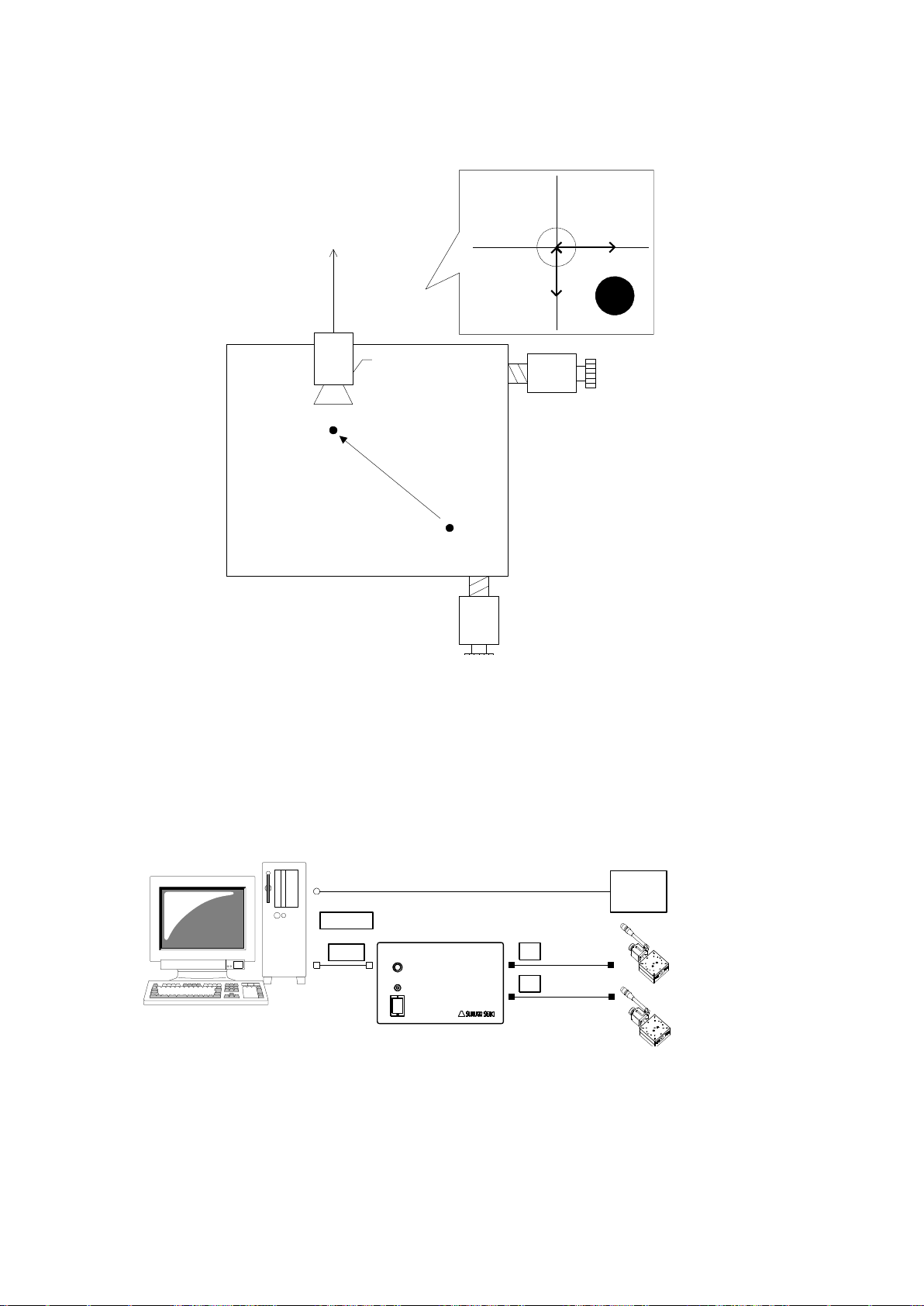
2.2.5 Move to arbitrary coordinate
Waiting point
Shooting point
(2000,3000)
Camera Unit
X,Y direction
positioning
correction
Xrv,Yrv
1
Xrv
Yrv
X axis stage
Y axis stage
DS102
Stepping Motor
Controller
DS102
Computer
Camera
X
Y
USB
RS232C
or
STEP1 : Shooting position move to(2000,3000)
STEP2 : Obtained positioning correction by camera unit
STEP3 : Move subject to the center based on positioning correction
Camera Unit
Output positioning correction of X,Y
direction from shooting center to subject
Shows how to move the stage base on data, which is downloaded, from external.
1) Configuration
Page 57

57
2) Operation Outline
MSComm1.Output = “AXI1:SELSP 0:F0 1000” ’X stage set up speed
MSComm1.Output = “AXI2:SELSP 1:F1 1000” ’Y stage set up speed
MSComm1.Output = “AXI1:GOABS 2000” ’X stage move to shooting point
MSComm1.Output = “AXI2:GOABS 3000” ’Y stage move to shooting point
intXrv = Obtain X direction correction position ( )
intYrv = Obtain Y direction correction position ( )
MSComm1.Output = “AXI1:PULS intXrv:GO CW” ’X stage move to correction position
MSComm1.Output = “AXI2:PULS intYrv:GO CW” ’Y stage move to correction position
Program contents
① Set up operation speed of X stage, Y stage.
② Move X stage, Y stage to shooting point. <STEP1>
③ Get positioning correction from camera units. <STEP2>
④ Move X stage, Y stage to correction point. <STEP3>
Program for stage is moved to arbitrary position to DS102 with the computer.
① Run the program from the computer.
3) Connection
Connect DS102
① Plug computer USB port into USB connector.
(In case of using RS232C, connect RS232C and computer)
② Connect X axis motor connector and X axis stage.
③ Connect Y axis motor connector and Y axis stage.
4) Programming
Page 58
58
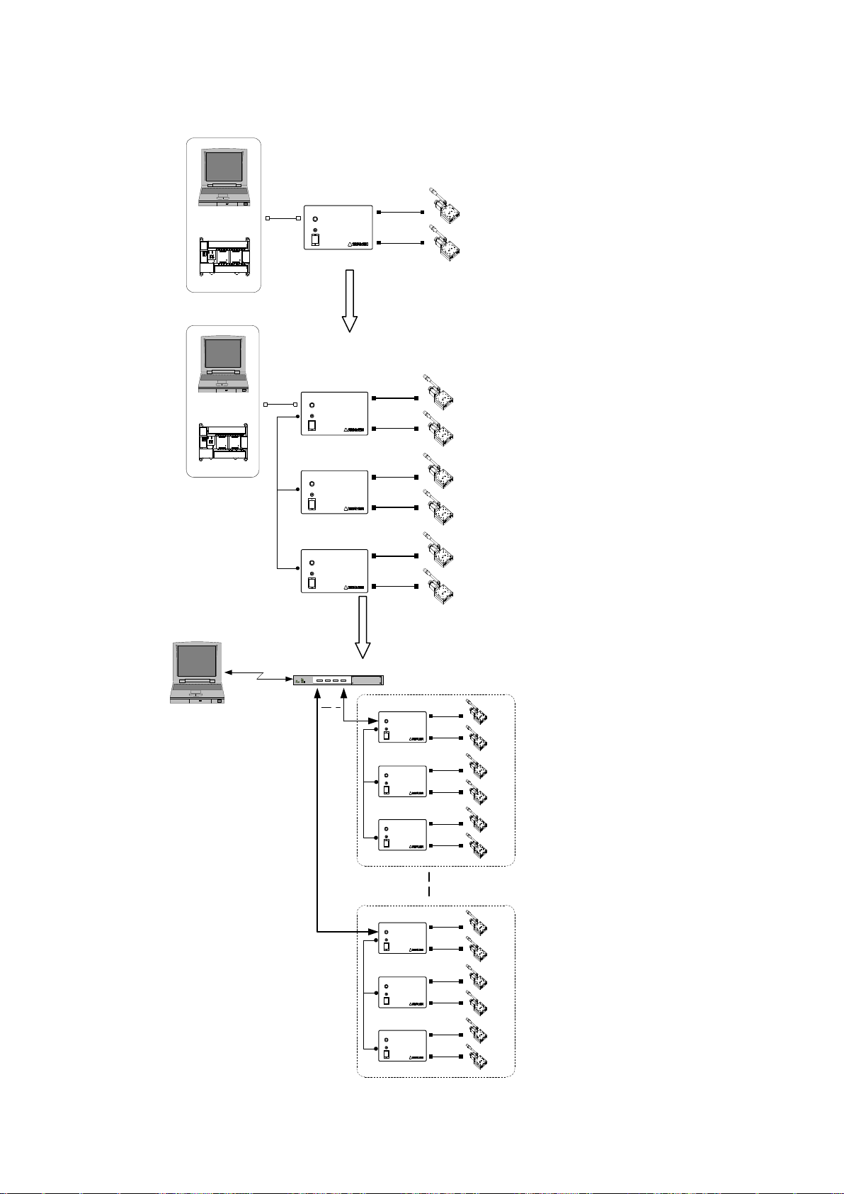
Controlled max. 24 axes
Using USB hub
Controlled max.6 axes
Using link cable
DS102
Stepping Motor
Controller
DS102
1axis
2axis
Computer
PLC
or
DS102
Stepping Motor
Controller
DS102
1axis
2axis
DS102
Stepping Motor
Controller
DS102
3axis
4axis
DS102
Stepping Motor
Controller
DS102
5axis
6axis
Computer
PLC
or
A
C
USBハブ
Computer
1set
Can be connected
max. 4sets
1axis
2axis
DS102
DS102
3axis
4axis
DS102
DS102
5axis
6axis
DS102
DS102
USB hub
19axis
20axis
DS102
DS102
21axis
22axis
DS102
DS102
23axis
24axis
DS102
DS102
2.2.6 Controlled over 3 axes
Can be controlled max.6 axes using link cable, and max.24 axes using USB hub.
Page 59
59
Type
DS102□□
DS102□□-IO
DS112□□
DS112□□-IO
Dimension
(Projection such as connector no included)
140(W)×300(D)×90(H)mm
70(W)×165(D)×155(H)mm
Weight
2.2kg
1.2kg
Usage environment
0~40℃ 20~80%RH(No condensation)
Storage environment
-20~60℃ 20~80%RH(No condensation)
Power supply input
AC100-240V ±10% 50/60Hz
DC24V±10% (3.5A 以上)
Maximum power consumption
Below 70W
Below 2.5A
Driver type
DS102NR/DS112NR :Normal (FULL/HALF)
DS102MS/DS112MS :Microstep(1/1~1/250)
Driver current rating
0.75A
Drive system
Bipolar Galvan static chopper pentagon drive system
Excitation system
DS102NR/DS112NR : 4-5 excitation(FULL/HALF)
DS102MS/DS112MS : 4 excitation(1/1~1/250)
Number of controlled axis
2 axes
Coordinate setting range
±99,999,999pulse
Driving speed setting range
1~999,999pps
Rate of rise speed setting range
1~9,999pps
Addition-subtraction speed setting
Range
1~9,999ms
S additional-subtraction speed rate
Setting range
0~100%
Machine limit
2 places for each axis to CW,CCW(Possible logic change)
Detected proximity origin
1 place for each axis(Possible logic change)
Detected origin
1 place for each axis(Possible logic change)
How to detect origin
12style
Home position
1 place for each axis(Can be set up in effective area arbitrarily)
External COM
Interface
RS232C:4,800~38,400bps(Dsub9pin male)
USB2.0:Full/Low Speed only(USB mini B terminal)
Controlled I/O(CNT-I/O):Input9points(24Vphoto coupler)、 Output11points(Open collector)
Link function
RS485(Can be connected link max. 3 controller 6 axes with DG chain )
Program function
8Programs(100steps/1program)
Can be controlled program number choice, start, stop with controlled I/O
Teaching function
64 points(Can be controlled intended point, move, stop with controlled I/O)
Interpolation function
6 axes linear interpolation(Easy linear interpolation on the link)
Controlled I/O (CNT-I/O)
Input 9points(P/T START,STOP)( 24V photo coupler)
Output 12points(X DRIVE,XCWLS)( Open collector)
General I/O (I/O)
(Option)
-
Input16 points
(24Vphoto coupler)
Output12 points
(Open collector)
-
Input16 points
(24Vphoto coupler)
Output12 points
(Open collector)
Item
SPEC
Remarks
Display
16 figures×2 lines
No backlight
Input
DC24V
Supply from DS102/DS112
Number of key
12keys
Click emboss12 keys
Cable length
1.5m
Can be extended till Max10m (Option)
Operation
Mode
11mode
Continue/Step/Absolute/Origin/Home/
Parameter/Program/Teaching/Input/Output/Remote
(Display time which receive a command from external controlled)
Outline
73(W)×130(D)×27(H)mm
Not included the screw and cable
Weight
280g
1.5m cable included
3.SPEC and FUNCTION
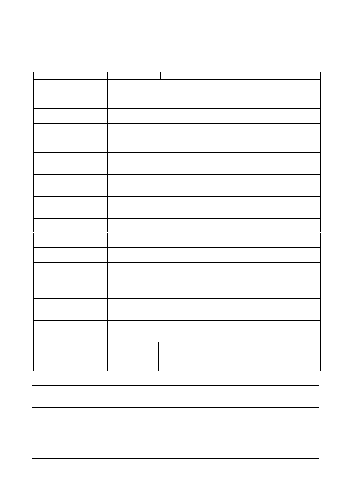
3.1 Basic SPEC
【Motor Controller DS102/DS112 (MISUMI Type: MSCTL102/MSCTL112)】
【Handy terminal DT100】
Page 60
60
3.2 Part name and functions
TERMINAL
DS102
Stepping Motor Controller
1
2
3
X Y
I/O
FUSE(250V 4A)
Normal Blow
5.2×20.0mm
Voltage
AC100-240V
Wattage
max 70W
Frequency
50/60Hz
CNT-I/O EMS SW1 LINK USB RS232C
9
8
7
6
5 4
11
12 13
10
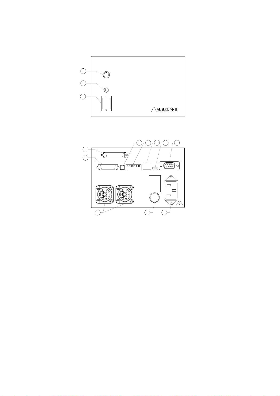
【DS102 (MISUMI Type: MSCTL102) Front panel】
【DS102 Rear panel】
① Power :Power switch
② LED :LED lights up when switch on
③ TERMINAL :Connector for handy terminal(DT100)
④ RS232C Connector :Connector for RS232C communication(Dsub9P male)
⑤ USB Connector :Connector for USB communication(Mini Btype)
⑥ Link Connector :Connector for connecting Link to DS102(Max 3 units)
⑦ Dip Switch(8bit) :RS232C Baud rate(2bit)、Link Number(2bit)、USB ID(2bit)、
Command response (1bit) setting up
⑧ EMS Connector :Connector for emergency stop input(Software interlock,B point)
(Included connector for EMS cancel)
⑨ CNT-I/O Connector :Check the each axis status, Select program operating number・Start・
Stop, Select teaching position number・Start・Stop I/O connector
(Bellows 26pin half pitch)
⑩ I/O Connector :General I/O(In 16points,Out12 points)connector
(Option) (Bellows 36pin half pitch)
⑪ Stage connector :Connector for Motorized stage(X axis,Y axis)
⑫ Fuse holder :Use 250V、4A Nomal blow glass fuse
⑬ AC inlet :Input AC100~240V 50/60Hz
(Connector type:09-0054-00-14(Binder products))。
Incase of AC100~120V, use attached electric cable
In case of AC200V, use with the proper cable
Page 61
61
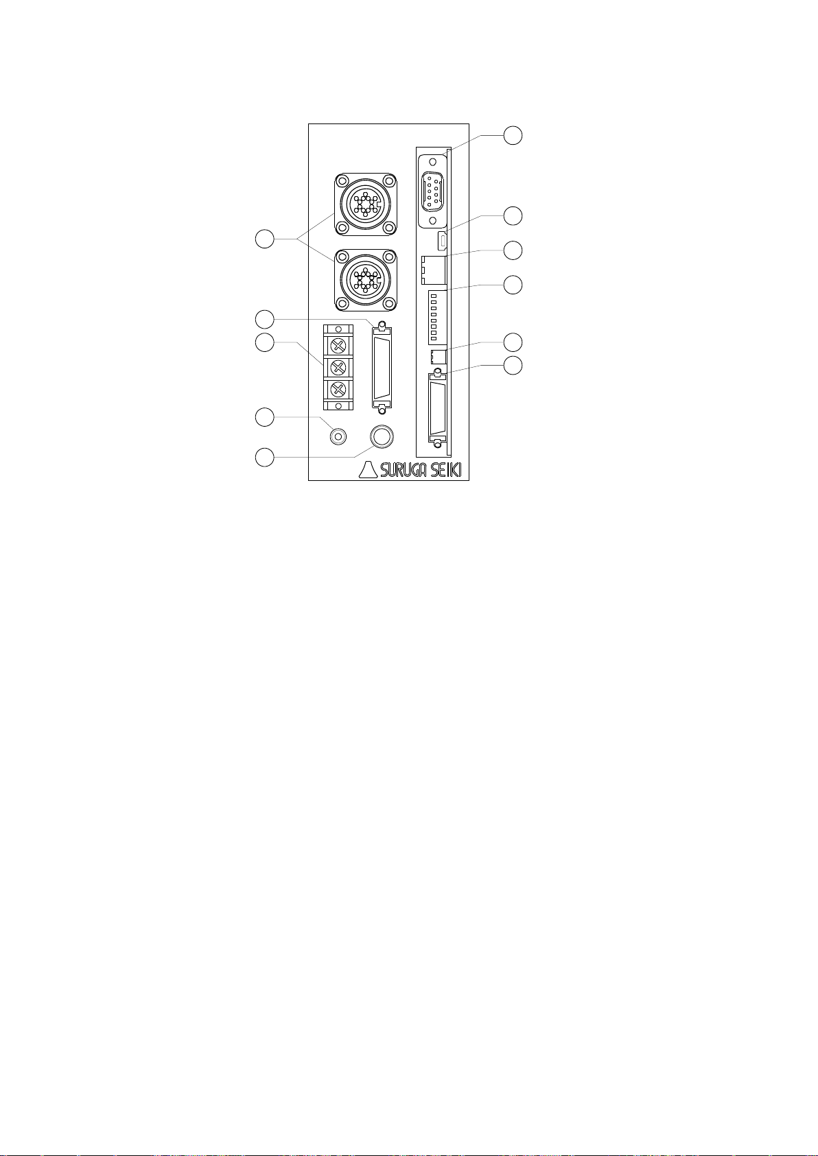
【DS112 (MISUMI Type: MSCTL112) Front panel】
XY
TERMINAL
POWER
+24V
CNT-I/O EMS SW1 LINK USB RS232C
DS112
Stepping Motor Controller
GNDFG
I/O
11
1
10
2
3
4
5
6
7
8
9
① Terminal block for power :For input(DC24V、M3 screw)
② POWER LED :LED lights up when power on
③ TERMINAL :Connector for handy terminal DT100
④ RS232C Connector :Connector for RS232C communications(Dsub9P male)
⑤ USB Connector :Connector for USB communications(Mini B type)。
⑥ Link Connector :Connector for link connection DS112(Max 3 units)
⑦ Dip SW(8bit) :Connector for RS232C baud rate(2bit),Link number(2bit),USB ID(2bit),
Command response (1bit) setting up
⑧ EMS Connector :Connector for emergency stop(Normal close)
(Included connector for EMS cancel)
⑨ CNT-I/O Connector :Check status each axis, select program operating number・Start・Stop
select the number of teaching position・Start・for stopI/O connector
(Bellows 26pin half pitch)
⑩ I/O connector :General I/O(In 16points,Out 12points)connector
(Option) (Bellows 36pin half pitch)
⑪ Stage connector :Motorized stage(Xaxis,Yaxis)for connecting
(Connector model:09-0054-00-14(Binder products))
Page 62
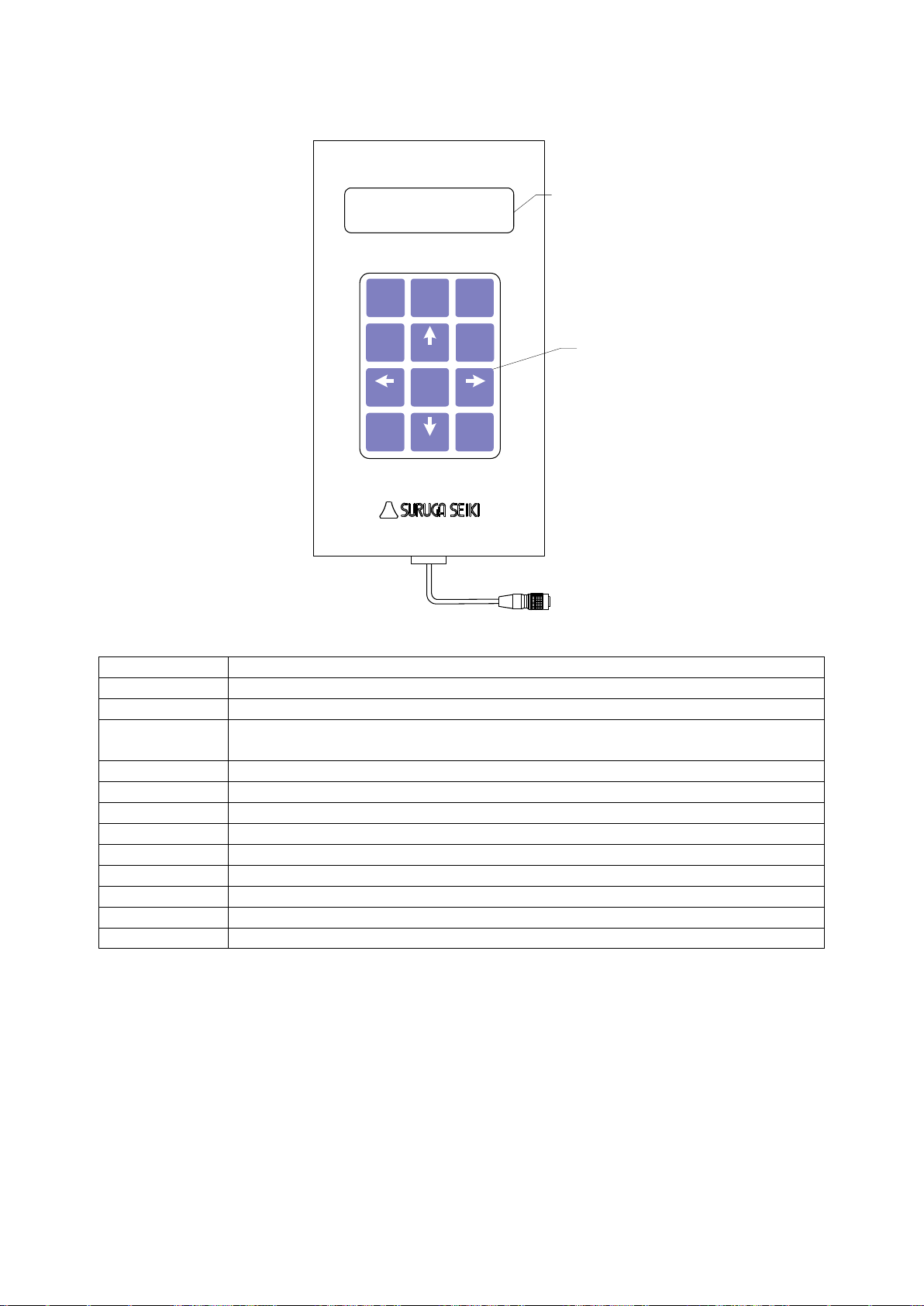
62
【DT100 (MISUMI Type: HDT100)】
Key name
Function
Jog/7
Operation mode(CNT/STP/ABS/ORG/HOM)transit to selection screen/7-key
Menu/8
Menu(PRM/PRG/TCH/IN/OUT)transit to selection screen /8-key
Set/9
Jump to setting value switchable screen for each operation mode(STP/ABS/ORG/HOM)、
Use at the teaching position registration /9-key
←/1
X axis to Cooperation, Select setting item /1-key
→/3
X axis to Cw operation, Select setting item /3-key
↑/5
Y axis to CW operation, Select setting item/5-key
↓/. -
Y axis to CCW operation, Select setting item/key .( decimal) -(negative)
SPD/4
Select speed table number /4-key
POS/6
Set current position /6-key
Link/2
Controller(axes)switching(at the link connecting)/2-key
STOP/ESC/0
Stop operating axes, stop program operating、return to previous screen /0-key
Enter
Decision
DT100
Handy Terminal
Stop
/ESC
0
Enter
. -
Jog7Menu8Set
9
SPD
4
POS
6
Link
2 31
5
DS102/DS112
1.5m
LCD:16 digit X 2 lines
Click emboss 12 keys
Page 63
63
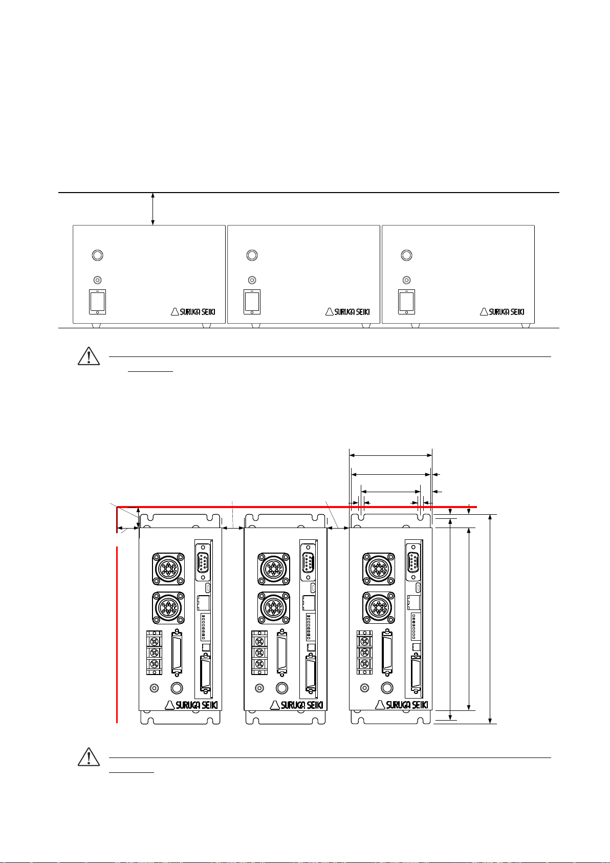
3.3 Setting
TERMINAL
DS102
Stepping Motor Controller
TERMINAL
DS102
Stepping Motor Controller
TERMINAL
DS102
Stepping Motor Controller
Over 20mm
155
70
X
Y
TERMINAL
POWER
+24V
CNT-I/O EMS SW1 LINK USB RS232C
DS112
Stepping Motor Controller
GNDFG
I/O
177.4
11.3
1.6
3.7
170
10
4.5 4.5
50
66
X
Y
TERMINAL
POWER
+24V
CNT-I/O EMS SW1 LINK USB RS232C
DS112
Stepping Motor Controller
GNDFG
I/O
Over 20mm
X
Y
TERMINAL
POWER
+24V
CNT-I/O EMS SW1 LINK USB RS232C
DS112
Stepping Motor Controller
GNDFG
I/O
Over 20mm
Over 20mm
Over 20mm
【DS102 (MISUMI Type: MSCTL102)series】
Please set DS102 on the level and vibration-free, and open the space over 20mm because of
eradiation on top of this unit.
No need to open the space in between controllers when line up the few units in one row
sideways.
If cover the upper radiation space, it is to be a cause of a fire and damage because of heat
up inside.
【DS112 (MISUMI Type: MSCTL112)series】
Should set up DS112 on the level with 4 mounted holes. In case of set up on the level, radiation
hole should be comes to upper or left side of units, please open over 20mm spaces.
If cover the upper radiation space, it is to be a cause of a fire and damage because of heat
up inside.
Page 64
64
3.4 External Interface
Pin No.
Signal
I/O
Function
1
T (+)
I/O
Transmitted and received data (+)
2
T (-)
I/O
Transmitted and received data (-)
3
GND
-
Ground 4 NC
-
Non connected
5
T (+)
I/O
Transmitted and received data (+)
6
T (-)
I/O
Transmitted and received data (-)
7
GND
-
Ground 8 NC
-
Non connected
9
GND
-
Ground
10
FG
-
Frame ground
3
4
Link number
OFF
OFF
0(Default)
ON
OFF
1
OFF
ON 2 ON
ON
1 2 3 4 5 6
ON
7
8
SW1
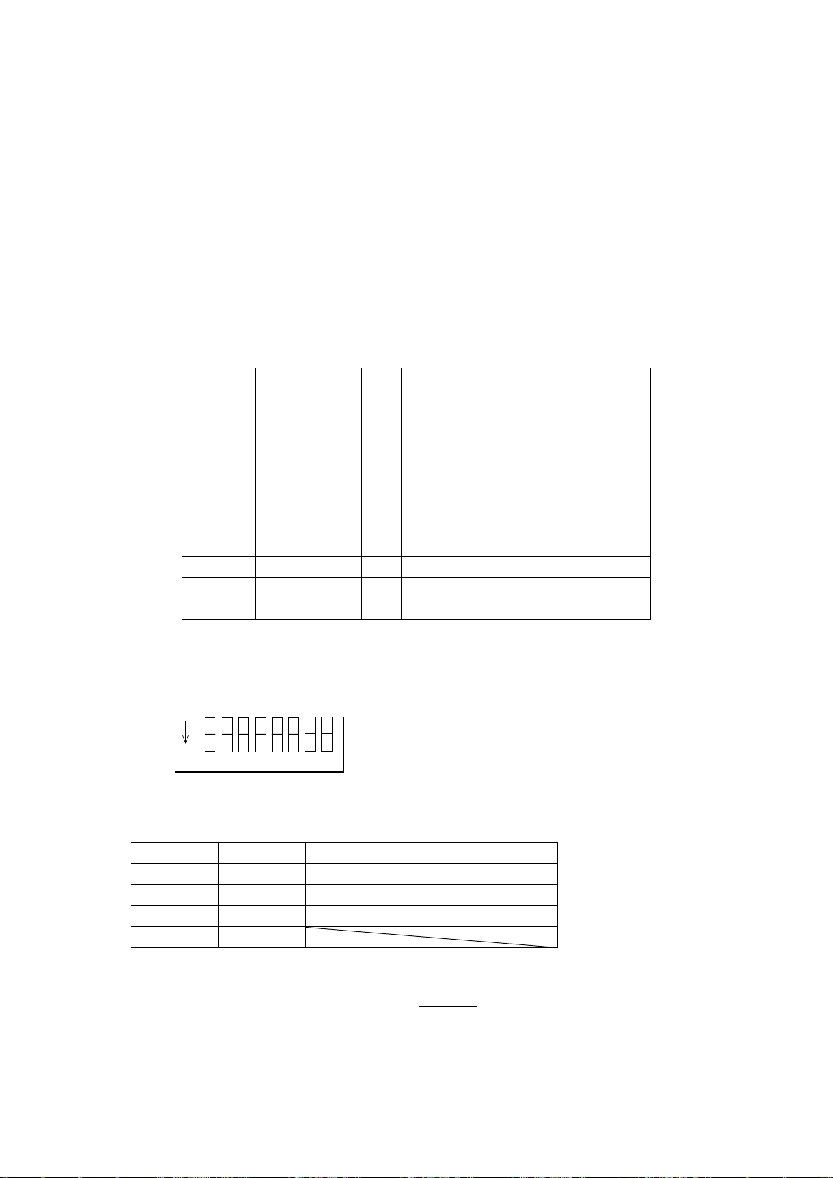
3.4.1 Link connection(Link)
In case of controlled over 3 axes, can be operated max.6 axes operations connected with original
link cable (DS100-LINK2-0.5 (MISUMI Type: MSLINK2-0.5) or DS100-LINK3-0.5 (MISUMI Type:
MSLINK3-0.5) between 2 units or 3 units of DS102/DS112. (MISUMI Type:
MSCTL102/MSCTL112)
【Link connector】
Connector type : S10B-PADSS-1(LF)(SN) (JST)
Matched plug : PADP-10V-1-S(LF)(SN) (JST)
Conformance contact : SPH-002T-P0.5L (JST)
※If use link function, need to set the ID number with DIP switch.
【Set the DIP switch】
Set third bit and forth bit of SW1
● Set link number
※Factory-setting is OFF.
※ Please power on in the order Link number 2,→1→0
In case of can’t be powered on in turn because of included system, please power on 3 units
at the same time.
Page 65
65
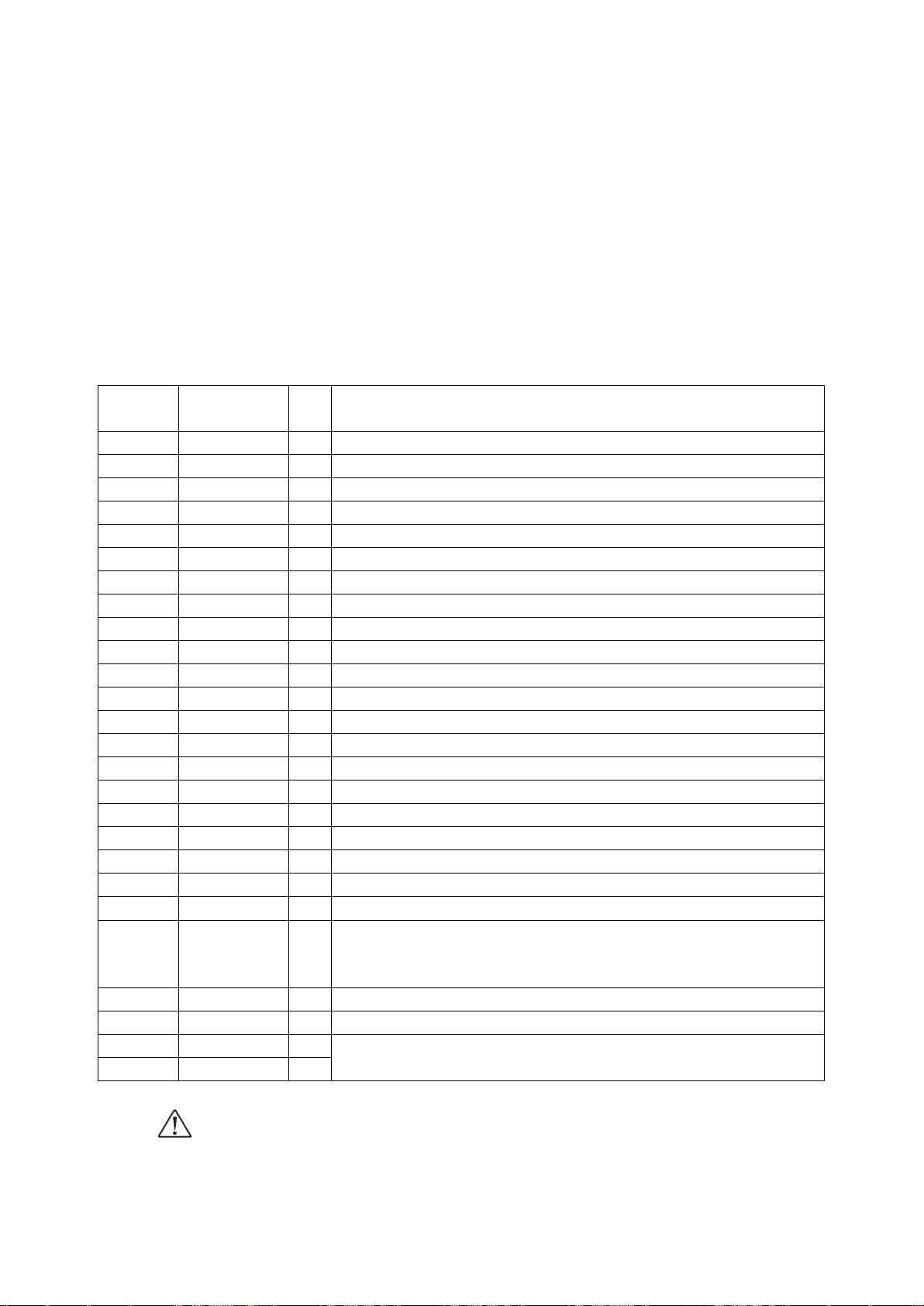
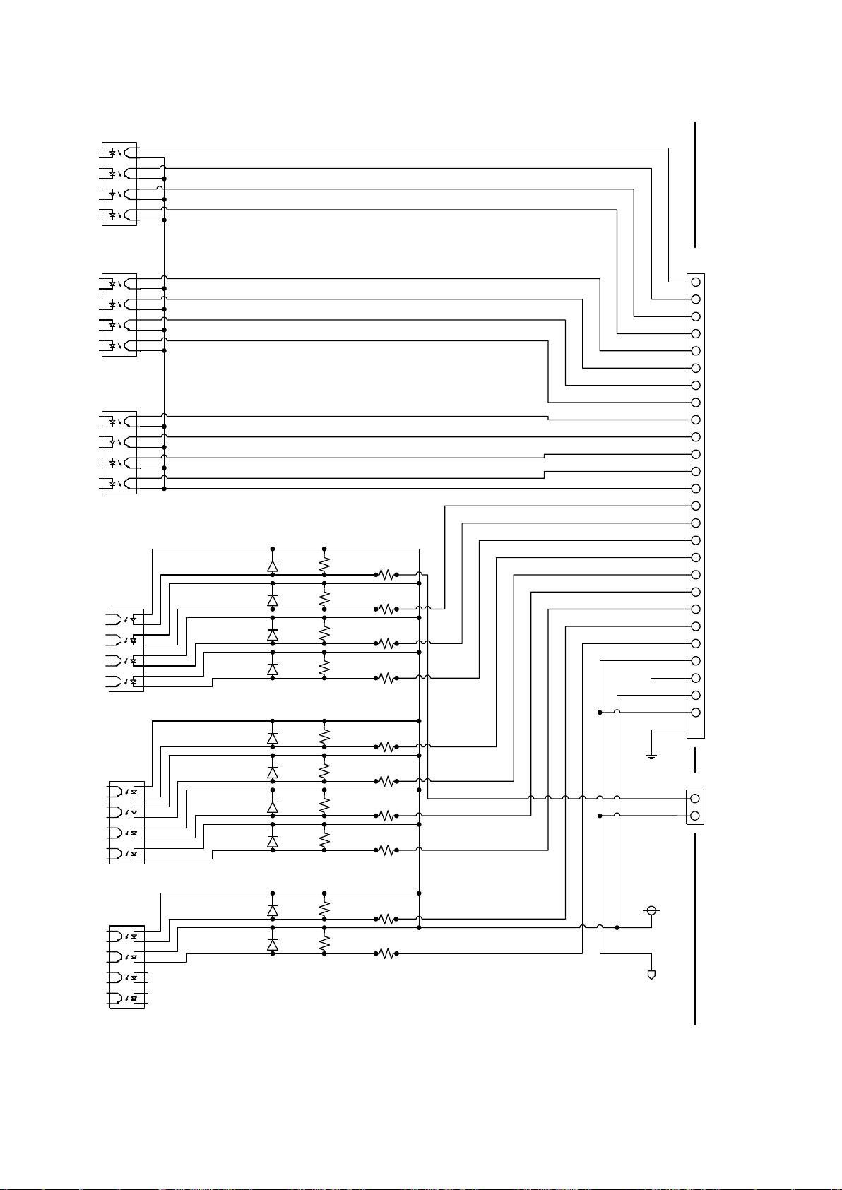
3.4.2 Control Input/Output(CNT-I/O)
Pin
number
Name of
signal
I/O
Function
1
X_DRIVE
O
X axis now driving
2
X_CWLS
O
X axis CWLS now detecting
3
X_CCWLS
O
X axis CCWLS now detecting
4
X_ORG
O
X axis ORG now detecting
5
Y_DRIVE
O
Y axis now operating
6
Y_CWLS
O
Y axis CWLS now detecting
7
Y_CCWLS
O
Y axis CCWLS now detecting
8
Y_ORG
O
Y axis ORG now detecting
9
READY
O
Ready output
10
NC
-
Non-connected(System reserved)
11
EMS
O
EMS now detecting (OFF for EMS detecting / On for EMS non detecting)
12
P/T_RUN
O
Program now driving or teaching point now moving
13
-COM1
-
Common for output signal
14
P/T_BIT0
I
Select program numberBIT0 or teaching point specification BITO
15
P/T_BIT1
I
Select program numberBIT1 or teaching point specification BIT1
16
P/T_BIT2
I
Select program numberBIT2 or teaching point specification BIT2
17
T_BIT3
I
Teaching point specification BIT3
18
T_BIT4
I
Teaching point specification BIT4
19
T_BIT5
I
Teaching point specification BIT5
20
P/T_START
I
Program driving start signal / Teaching point moving start signal
21
STOP
I
Program stop (All axes will be stopped)
22
PRG/TCH
I
Program driving mode/Switching teaching point moving signal
(When OFF、program driving mode/When ON、teaching point
moving mode)
23
-COM0
-
Common for input signal
24
NC
-
Non connected
25
DC+24V
O
Service power (DC24V,max 250mA)
26
0V
O
Output the status of motorized stages that connected DS102/DS112. Also can operated
teaching point number, specify program number, move teaching point, program operation start and
stop.
By connecting I/O of PLC and CNT-I/O, can be controlled the motorized stages easily.
【CNT-I/O connector】
Connector type : 10226-52A2PL (3M)
Matched connector(ex.): 10126-3000PE (3M)
【Option cable(2m)】
type : DS100-CNT-2 (MISUMI Type: MSCNT2)
【CNT-I/O pin assign】
Driving current of output circuit is 20mA/points, ON current of input circuit is
5mA/points.
-COM0 and -COM1 are insulated.
Page 66
66
1
2
3
4
5
6
7
8
9
10
11
12
13
14
15
16
17
18
19
20
21
22
23
24
25
26
CNT-I/O
X_DRIVE
Y_CCWLS
T_BIT3
P/T_BIT2
P/T_BIT1
P/T_BIT0
EMS
(Reserved)
READY
Y_ORG
Y_CWLS
Y_DRIVE
X_ORG
X_CCWLS
X_CWLS
T_BIT4
PRG/TCH
DC+24V
N.C.
-COM0
STOP
P/T_START
-COM1
P/T_RUN
T_BIT5
0V
EMS
EMS-
EMS+
1
2
E
24V+
0V
PS2801-4
PS2801-4
PS2801-4
PS2801-4
PS2801-4
PS2801-4
4.7k
4.7k
4.7k
4.7k
1.5k
1.5k
1.5k
1.5k
1.5k
1.5k
1.5k
1.5k
1.5k
1.5k
4.7k
4.7k
4.7k
4.7k
4.7k
4.7k
【CNT-I/O Circuit】
Page 67
67
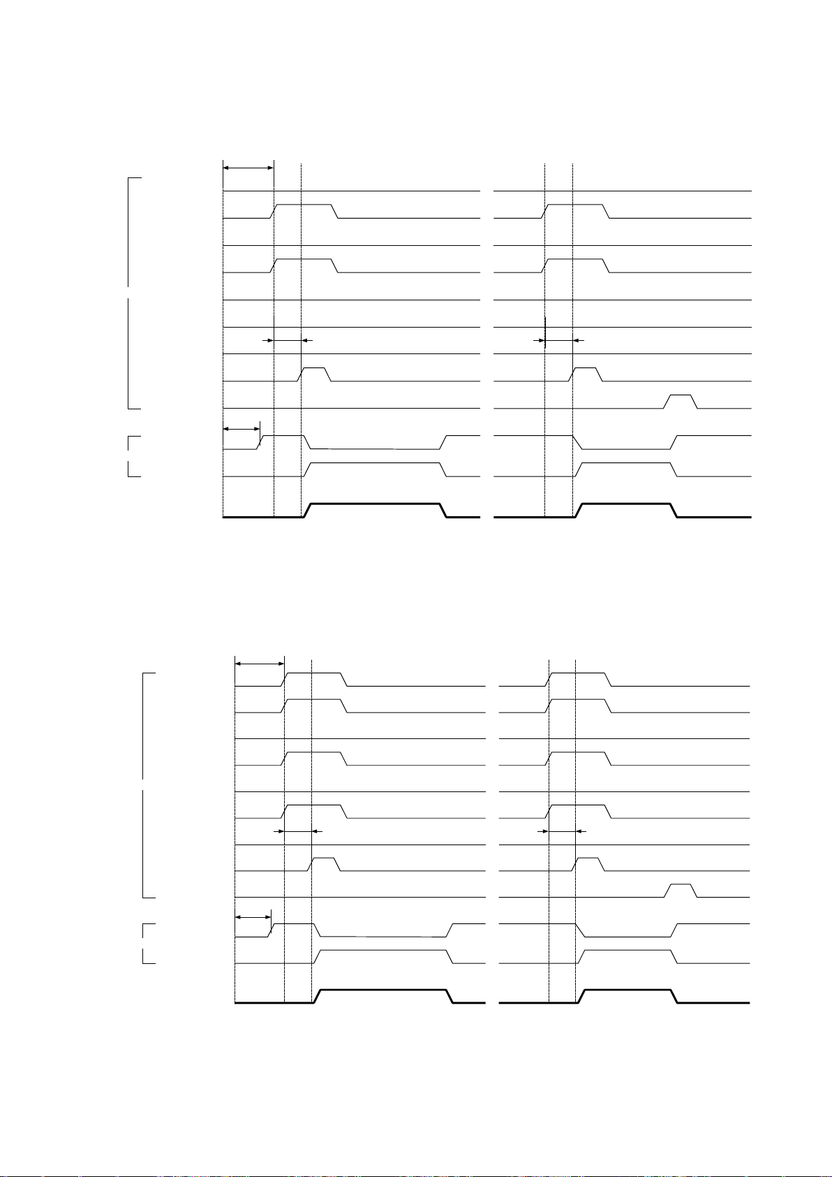
【Timing Chart】
PRG/TCH
P/T_START
P/T_RUN
P/T_BIT0
P/T_BIT1
P/T_BIT2
READY
T_BIT3
T_BIT4
T_BIT5
↑Start
On
Off
On
Off
On
Off
On
Off
On
Off
On
Off
On
Off
On
Off
On
Off
On
Off
Operating
Stop
↑PowerON
>5s
4s
>30ms
IN
OUT
STOP
On
Off
>30ms
↑Start
①Normal operation ②Suspend
PRG/TCH
P/T_START
P/T_RUN
P/T_BIT0
P/T_BIT1
P/T_BIT2
READY
T_BIT3
T_BIT4
T_BIT5
Teachingposition moving
↑Start
On
Off
On
Off
On
Off
On
Off
On
Off
On
Off
On
Off
On
Off
On
Off
On
Off
駆動中
停止
↑PowerON
>5s
4s
>30ms
IN
OUT
STOP
On
Off
>30ms
↑Start
①Nomal operation ②Suspend
①Program operated by CNT-I/O(Ex.:Program No.5)
※Documentation, transfer and delete of program (No.0~7) is started from computer.
②Teaching position moved by CNT-I/O(Ex.:Teaching No.21)
※ Registration of teaching position is started from computer or handy terminal DT100.
Page 68
68
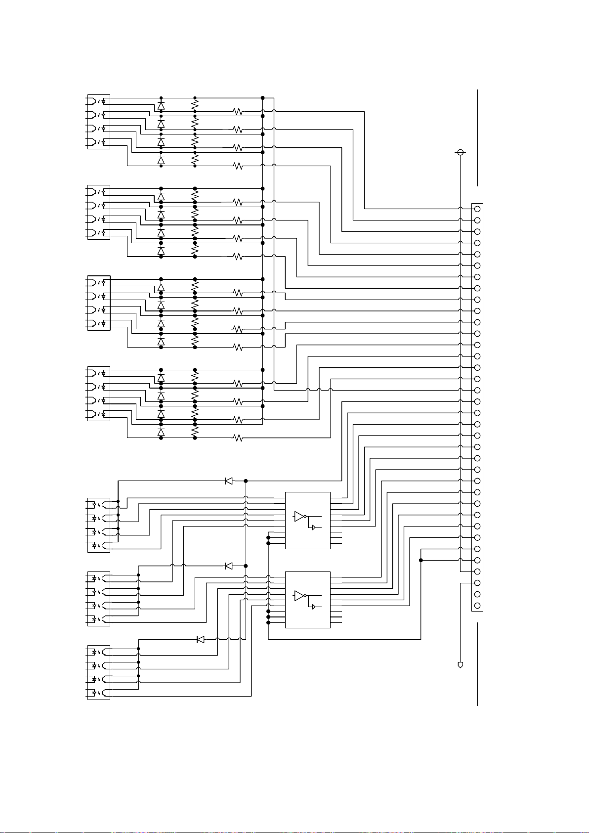
3.4.3 General I/O(I/O)( Option)
Pin No.
Signal name
I/O
Function
1
In_00
I
General input00
2
In_01
I
General input01
3
In_02
I
General input02
4
In_03
I
General input03
5
In_04
I
General input04
6
In_05
I
General input05
7
In_06
I
General input06
8
In_07
I
General input07
9
In_08
I
General input08
10
In_09
I
General input09
11
In_10
I
General input10
12
In_11
I
General input11
13
In_12
I
General input12
14
In_13
I
General input13
15
In_14
I
General input14
16
In_15
I
General input15
17
+COM2
I
In_00~In_15 for insulation power on
18
+COM3
I
OUT_00~OUT_11 for insulation power on
19
Out_00
O
General output00
20
Out_01
O
General output01
21
Out_02
O
General output02
22
Out_03
O
General output03
23
Out_04
O
General output04
24
Out_05
O
General output05
25
Out_06
O
General output06
26
Out_07
O
General output07
27
Out_08
O
General output08
28
Out_09
O
General output09
29
Out_10
O
General output10
30
Out_11
O
General output11
31
-COM3
-
Out_00~Out_11 for insulation power ground
32
-COM3
-
Out_00~Out_11 for insulation power ground
33
DC+24V
O
Service power (DC24V,max 400mA)
34
0V
O
35
NC
-
Non-connected
36
NC
-
Non-connected
There’s option for general I/O that is input 16 points and output 12 points due to control each
sensors, switches, magnet valves and indicator lights.
【I/O connector】 General I/O(I/O)( Option)
Connector type : 10236-0200 (3M)
Adaptive connector(Ex.) : 10136-3000PE (3M)
【Option cable(2m)】
Type : DS100-IO-2 (MISUMI Type: MSGP2)
【I/O pin assign】
Input ON current is 5mA/point、Output drive current is 60mA/point(Total
under 500mA)
DC+24V power, COM2 and COM are each insulated.
Page 69
69
【I/O Circuit】
1
2
3
4
5
6
7
8
9
10
11
12
13
14
15
16
17
18
19
20
21
22
23
24
25
26
I/O
IN_00
IN_06
+COM2
IN_15
IN_14
IN_13
IN_10
IN_09
IN_08
IN_07
IN_05
IN_04
IN_03
IN_02
IN_01
+COM3
OUT_03
OUT_06
OUT_05
OUT_04
OUT_02
OUT_01
IN_12
IN_11
OUT_00
OUT_07
24V+
0V
TLP281-4
TLP281-4
TLP281-4
TLP281-4
TLP281-4
TLP281-4
4.7k
4.7k
4.7k
4.7k
1.5k
1.5k
1.5k
1.5k
1.5k
1.5k
1.5k
1.5k
1.5k
1.5k
4.7k
4.7k
4.7k
4.7k
4.7k
4.7k
27
28
29
30
31
32
33
34
35
36
OUT_10
OUT_09
OUT_08
OUT_11
0V
N.C.
DC+24V
-COM3
-COM3
N.C.
TLP281-4
1.5k
1.5k
4.7k
4.7k
1.5k
1.5k
4.7k
4.7k
1.5k
1.5k
4.7k
4.7k
TD62084AFG
TD62084AFG
Page 70
70
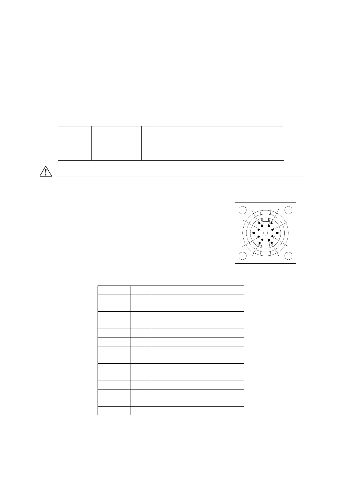
3.4.4 Emergency stop input(EMS)
Pin No.
Signal name
I/O
Function
1
EMS (+)
I
Input emergency stop signal (Normal close)
DC24V 5mA
2
EMS (-)
-
Common
Pin No.
I/O
Terminal function
A
O
Motor lead (Blue)
C
O
Motor lead (Red)
E
O
Motor lead (Orange)
G
O
Motor lead (Green)
J
O
Motor lead (Black)
L
I
CWLS input
M
I
CCWLS input
N
I
Near origin sensor input
O
I
Origin sensor input
P
O
Sensor power (DC5V(+))
R
O
Sensor power (DC5V(-))
S
-
N.C. T -
N.C. U -
Frame ground
A
P
O
N
M
L
R
J
T
S
GE
C
U
Can be emergency stopped all axes operating to open 1 pin and 2 pin of EMS connector.
(At the link connected, 3~6 axes that connected to Link No.1,2 is emergency stopped to open EMS
signal of Link No.0)
※ In case of no use EMS signal, please attached release-connector always on.
【EMS connector】
Connector type : S02B-PASK-2(LF)(SN) (JST)
Mattched plug : PAP-02V-S(LF)(SN) (JST)
Mattched contact : SPHD-001T-P0.5 (JST)
As software’s interlock function, please do not use as the last protect function of systems.
3.4.5 Stage interface
Connect the motorized stage connected cable to motor connector.
【Motorized stage connector】
Connector type : 09-0054-00-14 (Product of Binder: female)
Matched plug : 09-0341-02-14 (Product of Binder)
Page 71
71
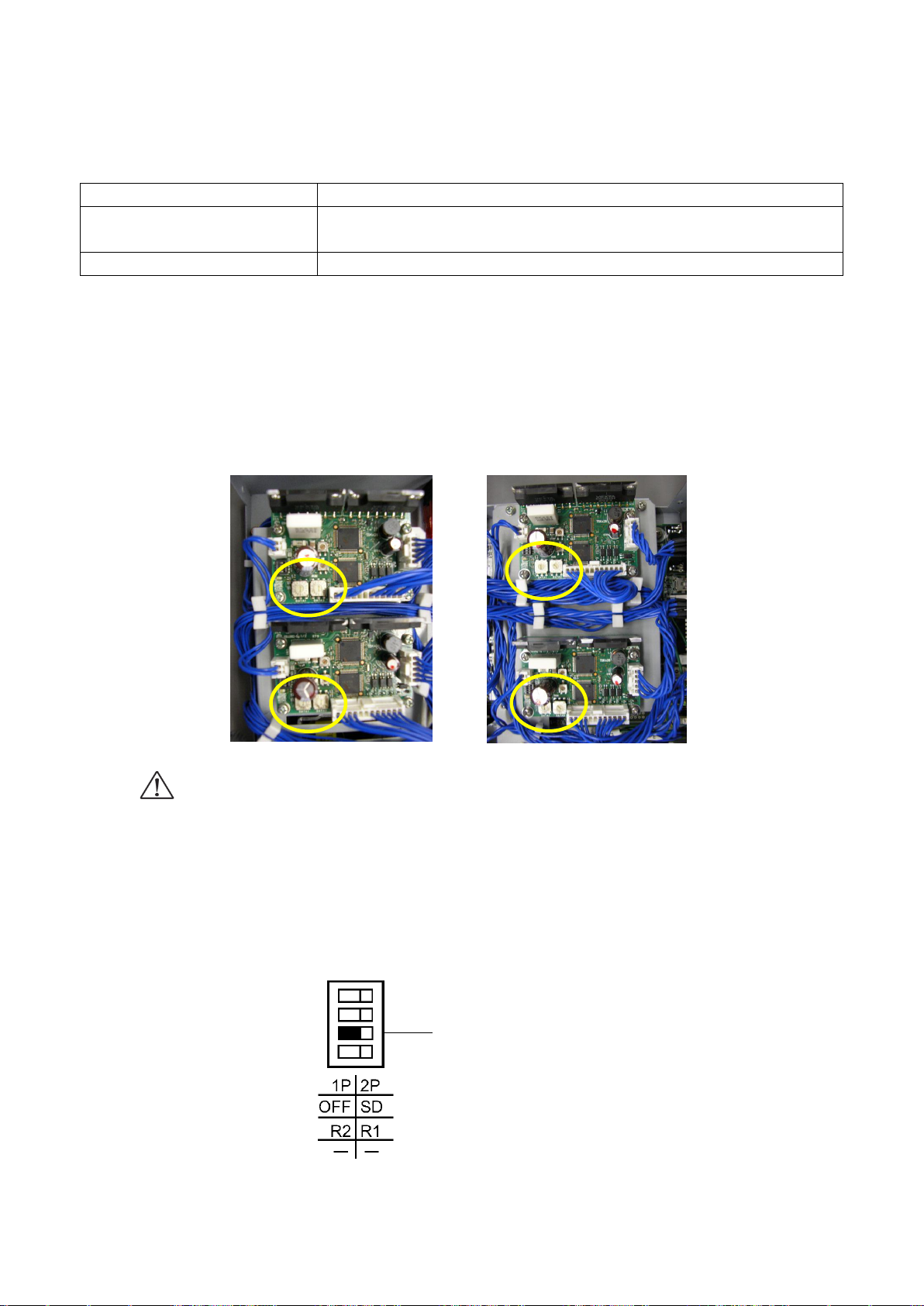
3.5 Driver division number setting
Driver type
Division number setting
Normal driver
Can be switched FULL/Half from handy terminal(DT100),control
software (DSCONTROL-WIN), communication command.
Micro step driver
Need to open the cover and set the rotary switch of micro-step driver.
Y axis
X axis
X axis
Y axis
Division number changing-over switch
Different how to set the division number normal type and micro-step type.
3.5.1 Open and shut
①In case of DS102, take out 10 screws from side of cover, in case of DS112, take out 6 screws
from side of cover with cross screwdriver.
②See following picture, set the marked point with precision screwdriver.
<DS102MS> <DS112MS>
・ Please power off during the open and shut, cause fire, injury and device breakage.
・ Please do not set up the driver with charged hands, cause breakage by static
electricity.
3.5.2 Setting division number
When set division number, please check driver’s division changing-over switch to [R1].
Default setting:R1
Page 72
72
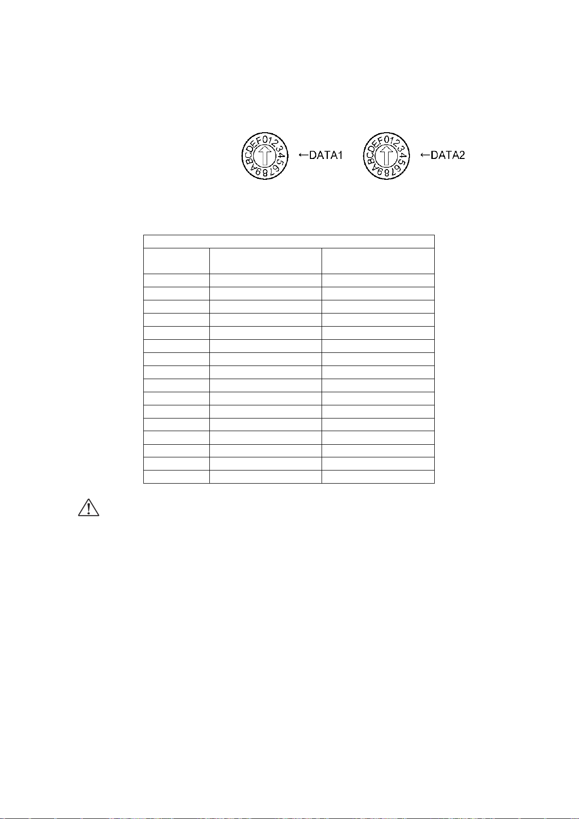
There are 2 division number setting switch [DATA1][DATA2], use [DATA1]here.
R1
DATA1
(DATA2)
Division number
Motor step angle
0
1/1
0.72°
1
1/2
0.36°
2
1/2.5
0.288°
3
1/4
0.18°
4
1/5
0.144°
5
1/8
0.09°
6
1/10
0.072°
7
1/20
0.036°
8
1/25
0.0288°
9
1/40
0.018°
A
1/50
0.0144°
B
1/80
0.009°
C
1/100
0.0072°
D
1/125
0.00576°
E
1/200
0.0036°
F
1/250
0.00288°
Can be used [DATA2] at the only use communication command. Please refer to 4, 3, 5, 2
paragraph.
In case of change the division number, change [DATA1].
Default setting: [DATA1 : 0]
[DATA2:0]
Following chart shows basic step angle 0.72°/STEP.
Resolution = Basic step angle × Division number
Please set “PULSE” as unit setting, in case of using both DATA1 and DATA2.
Division number are theoretical figure.
Please do not change the division number switch during operation, motor might be
stopped.
3.6 Smooth drive function(only MS type)
This function can get low vibration and low noise during slow operating without any change the
division number setting. It divides automatically into 1/16 pulse signal.
No need pulse changing(speed and pulse) of upper controller side. Smooth drive function must
be operated case of division number [R1],[DATA:0]~[DATA:6]([R2]cannot be set)
([DATA]numeric shows 3.5.2 paragraph division number switch [DATA1])
Page 73
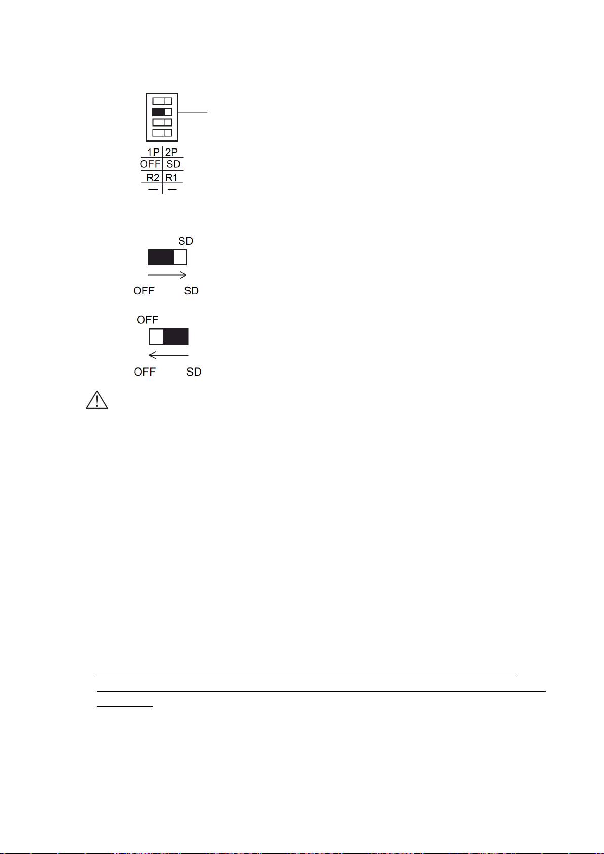
73
Smooth drive changing-over switch
Default setting:[SD:Operate smooth drive]
• When operate smooth drive function、set [SD]side.(Initialization)
• When no operate smooth drive function, set [OFF]side.
・Smooth drive function will not work when set over 10 divide division number.
Might be ignored to set[SD].(Same as[OFF]operation)
3.7 Units setting function
No need difficulty change from pulse to actual displacement.
Units setting must be first for each setting parameter. Follow the below.
① Units setting(pulse, μm, mm, deg, mrad)
② Set 1 pulse displacement at the full step(Basic resolution)set.
③ Set the division number(1/1~1/250)
④ 1pulse displacement(Automatically calculated from ①~③)
Example) In case of set the stage:KXC06020-G(1μm/pulse)to mm.
Units:mm
1 pulse displacement at the full step:0.001(mm)
Division number:1/20
1pulse displacement:0.00005(mm)
※ After setting, can use operate the setting units for all position data (except speed table).
※ In case of Sine Motion Stage(KRB04017, KRB06011, KGB07), can use only “PULSE ” as
unit setting.
Page 74
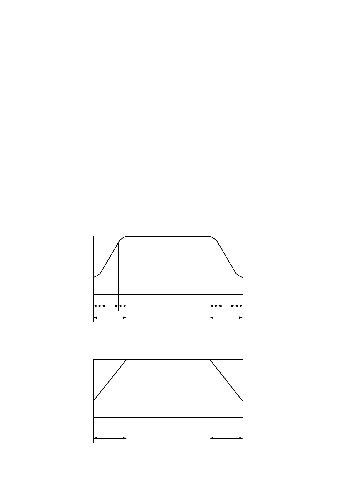
74
3.8 Speed setting(Speed table)
F(pps)
L(pps)
R(msec) R(msec)
S=0% S=0%
F(pps)
L(pps)
R(msec) R(msec)
S/2
(%)
S/2
(%)
S/2
(%)
S/2
(%)
100-S
(%)
100-S
(%)
This equipment memorized 10 speed table from 0 to 9. Each 2 axes(Max6 axes at Link) speed
is selected from speed table 0 to 9.
How to set the speed as shown bellows.:
① Select speed table from 0 to 9 as needed.
② Fix the speed table and change the setting level.
Example)
X axis・・・Speed table No.0 Fixed
Y axis・・・Speed table No.1 Fixed
Z axis・・・Speed table No.2 Fixed
U axis・・・Speed table No.3 Fixed
V axis・・・Speed table No.4 Fixed
W axis・・・Speed table No.5 Fixed
Set as above, and change the each speed table 0 to 5 setting level (L,F,R,S).
※ Control software (DSCONTROL-WIN) speed is set by ②
※ Can change speed in operation.
Start-up speed(L:pps)、Driving speed(F:pps)、Acceleration and deceleration rate
(R:msec)and S acceleration and deceleration rate(S:%)are as follows.:
(S=0%:trapezoid driving)
Page 75
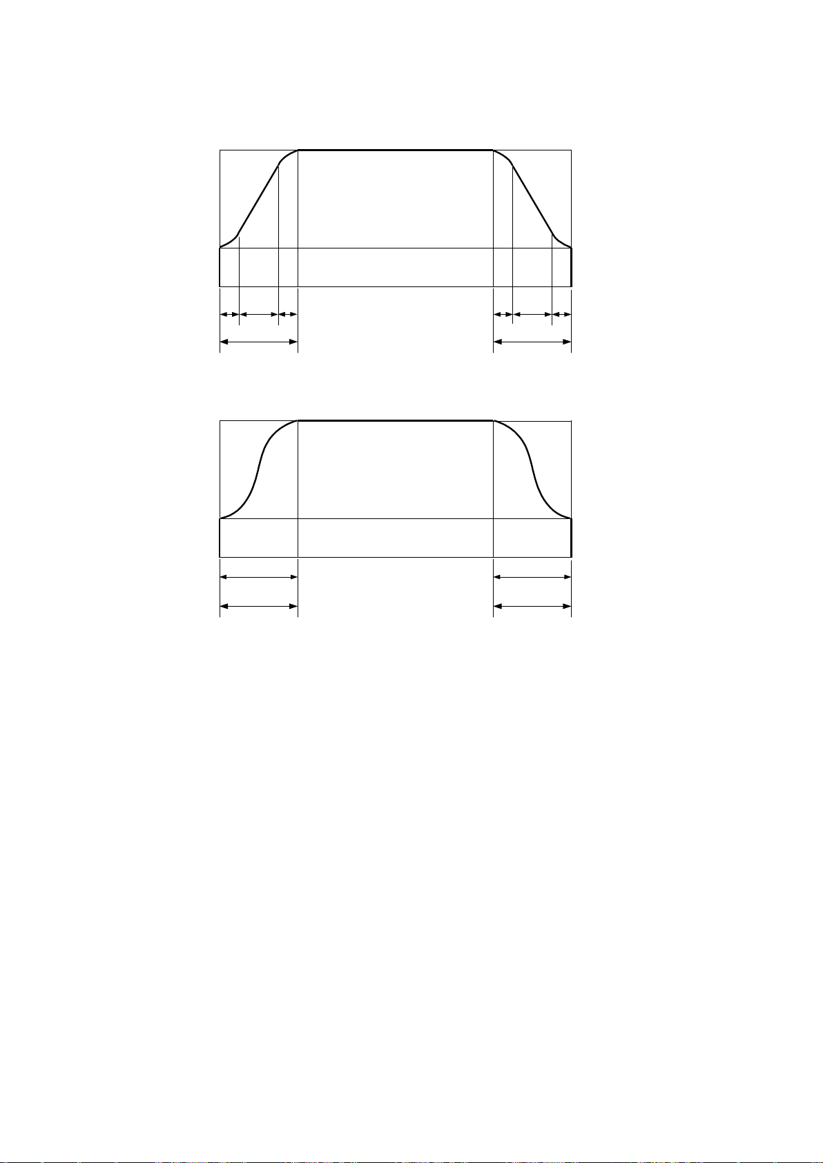
75
F(pps)
L(pps)
R(msec)
S=50% S=50%
R(msec)
25%
25%
25% 25%
F(pps)
L(pps)
R(msec)
S=100% S=100%
R(msec)
(S=50%)
(S=100%)
In case of bellows, set S acceleration and deceleration rate over 0 which helps to lessen the impact
and vibration for stages.
In case of under heavy load on the stages
In case of operating stages at the vertical (Z axis).
Become triangle driving at the trapezoid driving due to small distance(Avoid triangle driving)
Page 76
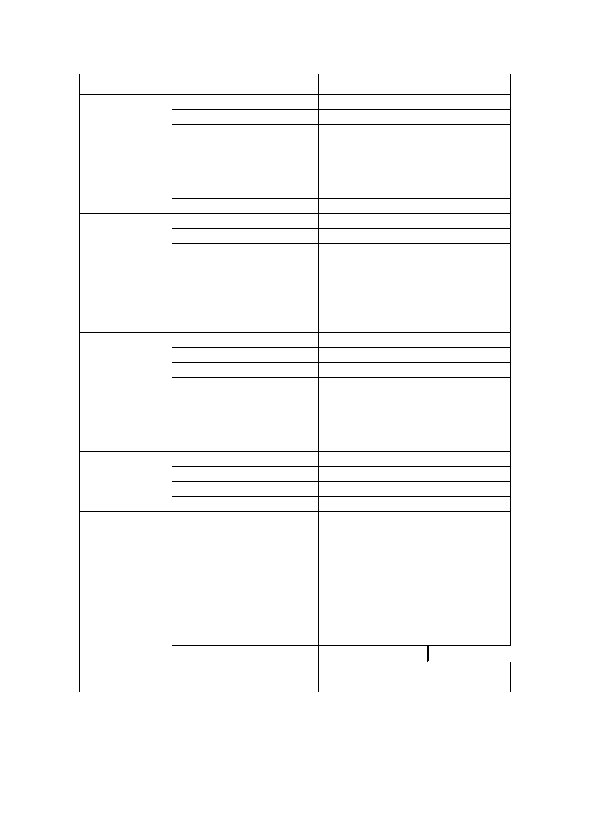
76
Speed table each level 0~9 as bellows.:
Contents
Setting range
Default
Speed table
No.0
Start-up speed(L)
1~9999pps
10pps
Driving speed(F)
1~999999pps
10pps
Acceleration and deceleration rate(R)
1~9999msec
1msec
S Acceleration and deceleration rate(S)
0~100%
0%
Speed table
No.1
Start-up speed(L)
1~9999pps
50pps
Driving speed(F)
1~999999pps
50pps
Acceleration and deceleration rate(R)
1~9999msec
1msec
S Acceleration and deceleration rate(S)
0~100%
0%
Speed table
No.2
Start-up speed(L)
1~9999pps
100pps
Driving speed(F)
1~999999pps
100pps
Acceleration and deceleration rate(R)
1~9999msec
1msec
S Acceleration and deceleration rate(S)
0~100%
0%
Speed table
No.3
Start-up speed(L)
1~9999pps
100pps
Driving speed(F)
1~999999pps
500pps
Acceleration and deceleration rate(R)
1~9999msec
100msec
S Acceleration and deceleration rate(S)
0~100%
0%
Speed table
No.4
Start-up speed(L)
1~9999pps
100pps
Driving speed(F)
1~999999pps
1000pps
Acceleration and deceleration rate(R)
1~9999msec
100msec
S Acceleration and deceleration rate(S)
0~100%
0%
Speed table
No.5
Start-up speed(L)
1~9999pps
100pps
Driving speed(F)
1~999999pps
2000pps
Acceleration and deceleration rate(R)
1~9999msec
100msec
S Acceleration and deceleration rate(S)
0~100%
0%
Speed table
No.6
Start-up speed(L)
1~9999pps
100pps
Driving speed(F)
1~999999pps
5000pps
Acceleration and deceleration rate(R)
1~9999msec
100msec
S Acceleration and deceleration rate(S)
0~100%
0%
Speed table
No.7
Start-up speed(L)
1~9999pps
1000pps
Driving speed(F)
1~999999pps
10000pps
Acceleration and deceleration rate(R)
1~9999msec
100msec
S Acceleration and deceleration rate(S)
0~100%
0%
Speed table
No.8
Start-up speed(L)
1~9999pps
1000pps
Driving speed(F)
1~999999pps
20000pps
Acceleration and deceleration rate(R)
1~9999msec
100msec
S Acceleration and deceleration rate(S)
0~100%
0%
Speed table
No.9
Start-up speed(L)
1~9999pps
1000pps
Driving speed(F)
1~999999pps
50000pps
Acceleration and deceleration rate(R)
1~9999msec
100msec
S Acceleration and deceleration rate(S)
0~100%
0%
※ The value of speed table No.9 is max speed which can use at this equipment. Ex) If the value
of over 50000pps is setting on speed table No.1, actual speed is 50000pps. If needed, please
change the value of speed table No.9.
Page 77
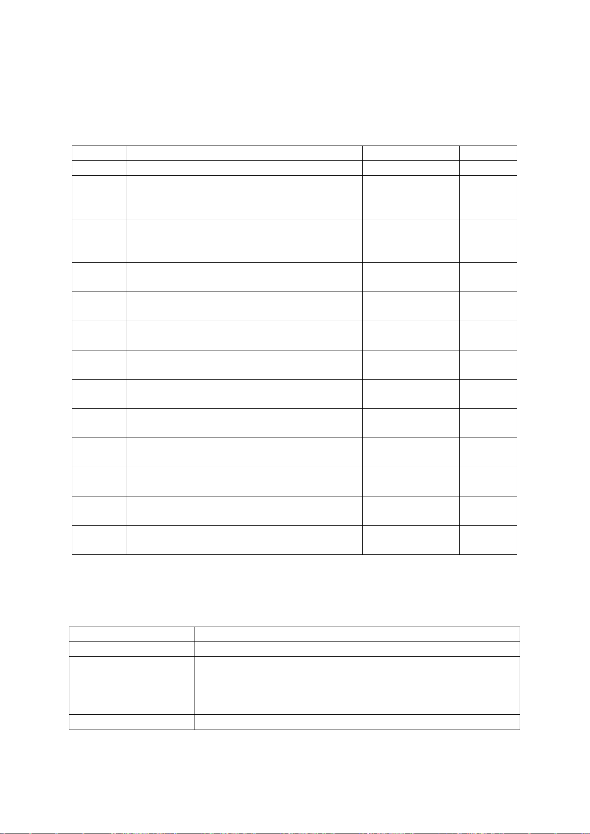
77
3.9 Function of origin return
TYPE
OPERATION
APPLIED SENSOR
PAGE
Type0
Origin return is not implemented(default)。
-
P.78
Type1
Start to detect to the CCW
Detect the CW side edge of NORG signal, then,
Detect the CCW side edge of ORG signal
CWLS/NORG
/ORG/CCWLS
P.78
Type2
Start to detect to the CW
Detect the CCW side edge of NORG signal, then
Detect the CW side edge of ORG signal
CWLS/NORG
/ORG/CCWLS
P.79
Type3
Start to detect to the CCW
Detect the CCW side edge of ORG signal
CWLS/ORG/
CCWLS
P.80
Type4
Start to detect to the CW
Detect the CW side edge of ORG signal
CWLS/ORG/
CCWLS
P.80
Type5
Start to detect to the CCW
Detect the CW side edge of CCWLS signal
CWLS/CCWLS
P.81
Type6
Start to detect to the CW
Detect the CCW side edge of CWLS signal
CWLS/CCWLS
P.81
Type7
After operated type1, detect CCW side edge of
TIMING signal
CWLS/NORG
/ORG/CCWLS
P.82
Type8
After operated type2, detect CW side edge of
TIMING signal
CWLS/NORG
/ORG/CCWLS
P.82
Type9
After operated type3, detect CCW side edge of
TIMING signal
CWLS/ORG/
CCWLS
P.82
Type10
After operated type4, detect CW side edge of
TIMING signal
CWLS/ORG/
CCWLS
P.82
Type11
After operated type 5, detect CCW side edge of
TIMING signal
CWLS/CCWLS
P.82
Type12
After operated type 6, detect CW side edge of
TIMING signal
CWLS/CCWLS
P.82
Type of origin return
Stages
1、2、7、8
KS102、KS103、KS111、KS112、KS121、KS122、KXS
3、4、9、10
PG、KX、KS101、KS161、KS162、KS332、KS401、KS402、
KS501-60、KG05、KG07、KGB07、KH06、KH07、KS421、KS451、
KGW、KRW、KXC、KXG、KXL(ORG option) 、KXB、
KXS(option Q,W) 、KXT、KHE、KRE
5、6、11、12
KS501-40、KRB04017、KRB06011、KXL
This equipment has built-in 12 types origin return pattern. Please select origin returning type
according to the part number of stage you use.
<List of origin return types>
※ Please refer motorized stages catalog, select pattern type of origin return with checking the
usage sensor.
<Recommended origin return method>
Recommended origin return method with usage our stages as bellows.:
※PG series, KX series, KG05、KG07、KGB07、KH06、KH07 case of using standard cable.
Page 78
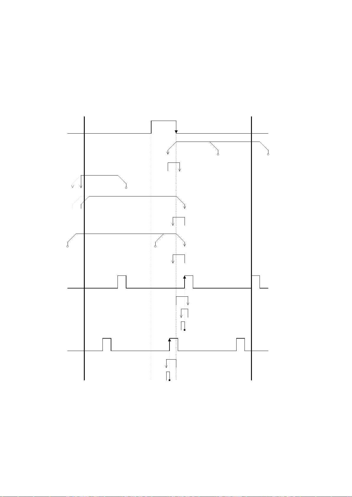
78
The Origin return sequence is shown as below.:
CWLS
start
position2
Fspeed
Lspeed
Lspeed
SD
Start position3
LD
Start position4
bpoint
JD
JOG
NORG
ORG
(Sensor is
turned OFF
when the point
a is detected)
<Near origin
detection process>
<Origin detection
process>
CCWLS
point a
Start
position1
Fspeed
Lspeed
Fspeed
Lspeed
SD
Lspeed
Start position
5
Fspeed
Lspeed
SD
Lspeed
Lspeed
SD
Lspeed
JD JOG
ORG
(Sensor is
turned ON when
the point a is
detected)
SD
b点
Lspeed
Solid-line shows emergency
stop setting. Dot-line shows
slowdown stop setting.
※
※
【Type0】
No origin return(default)
【Type1】
CW side edge (a point) of NORG signal is detected in CCW direction, then CCW side edge (b point)
of ORG signal.
Page 79
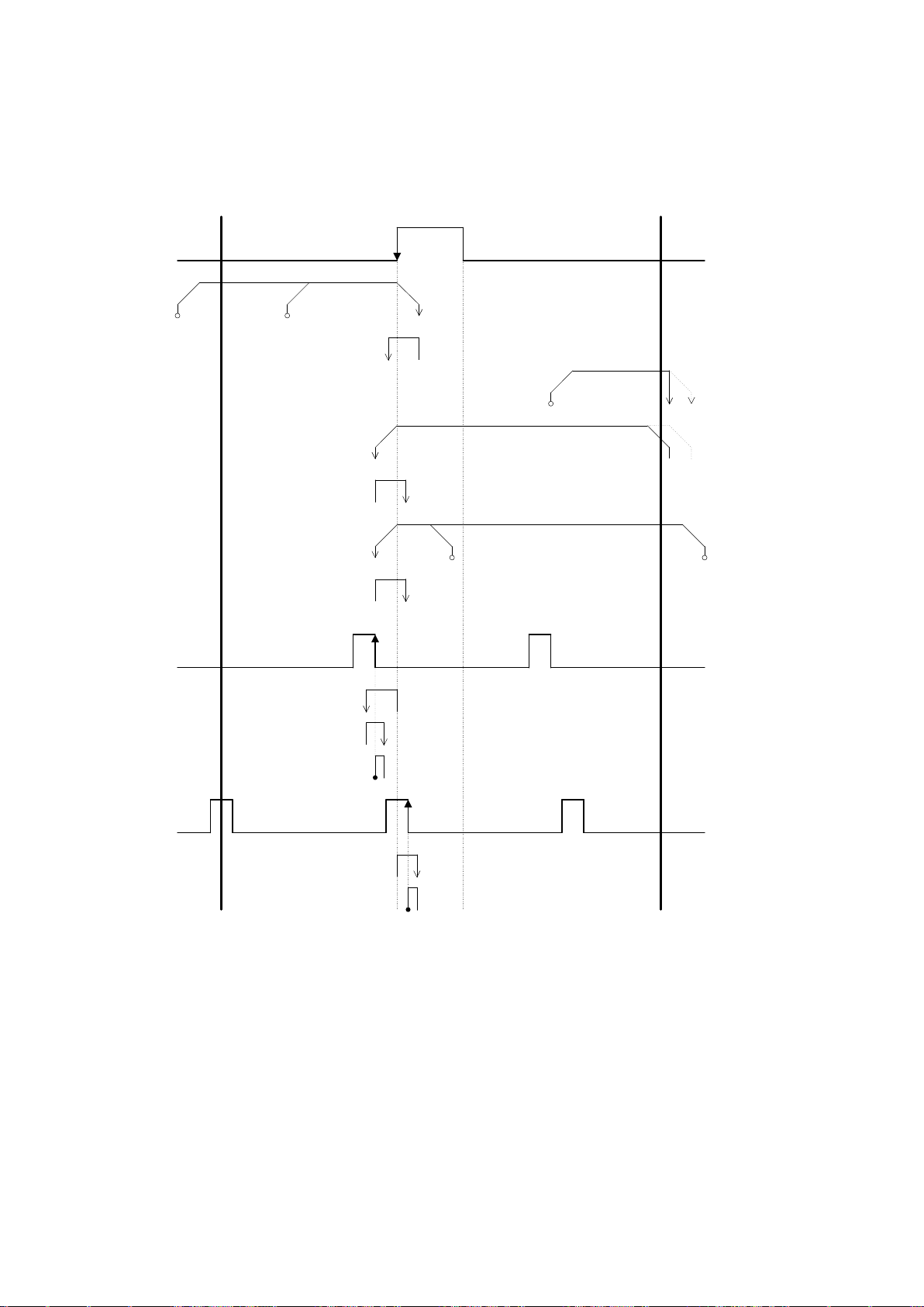
79
【Type2】
CWLS
Start
position2
Fspeed
Lspeed
Lspeed
SD
start position3
NORG
ORG
(Sensor is
turned OFF
when the point
a is detected)
<Near origin
detection process>
<Origin detection
process>
CCWLS
point a
Start
position1
Fspeed
Lspeed
Fspeed
Lspeed
SD
ORG
(Sensor is turned
OFF when the
point a is
detected)
LD
Lspeed
Start position4
Start
position5
Fspeed
Lspeed
SD
Lspeed
point b
JD
JOG
Lspeed
SD
Lspeed
JDJOG
SD
point b
Lspeed
※
※
Solid-line shows emergency
stop setting. Dot-line shows
slowdown stop setting.
CCW side edge (a point) of NORG signal is detected in CW direction, then CW side edge (b
point) of ORG signal is detected.
Page 80
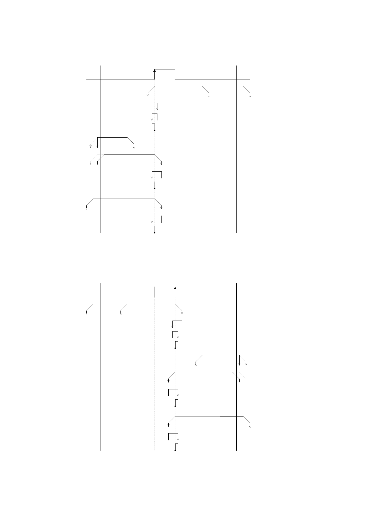
80
【Type3】
CWLS
Start
position2
Fspeed
Lspeed
Lspeed
SD
Start position3
LD
Start
position4
CCWLS
apoint
Start position
1
Fspeed
Lspeed
Fspeed
Lspeed
SD
Lspeed
Fspeed
Lspeed
SD
Lspeed
JD
JOG
SD
Lspeed
ORG
<Origin detection
process>
JD
JOG
JD
JOG
※
※
Solid-line shows emergency
stop setting. Dot-line shows
slowdown stop setting.
CWLSCCWLS
apoint
ORG
<Origin detection
process>
Start
position2
Fspeed
Lspeed
Lspeed
SD
Start
position1
JD
JOG
SD
Lspeed
Start position3
LD
Fspeed
Lspeed
Fspeed
Lspeeed
SD
Lspeed
JD
JOG
Start
position4
Fspeed
Lspeed
SD
Lspeed
JD
JOG
※
※
※Solid-line shows
emergency stop setting.
Dot-line shows slowdown
stop setting.
CCW side edge (a point) of ORG signal is detected in CCW direction
【Type4】
CW side edge (a point) of ORG signal is detected in CW direction.
Page 81
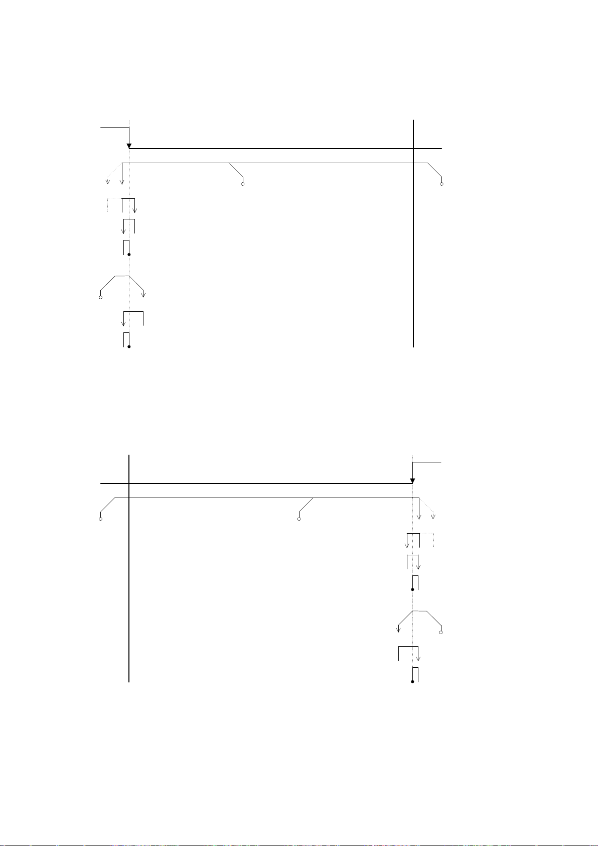
81
【Type5】
CCWLS(a point)
CCWLS
Start
position2
Fspeed
Lspeed
Lspeed
SD
Start
position1
JD
JOG
SD
Lspeed
CWLS
Start
position3
Fspeed
Lspeed
SD
Lspeed
JD
JOG
※
※Solid-line shows
emergency stop setting.
Dot-line shows slowdown
stop setting.
※
CCWLS
CCWLS
CWLS(a point)
Start
position2
Fspeed
Lspeed
Lspeed
SD
Start
position1
JD
JOG
SD
Lspeed
Start
position3
Fspeed
Lspeed
SD
Lspeed
JD
JOG
※
※Solid-line shows
emergency stop setting.
Dot-line shows slowdown
stop setting.
※
CW side edge (a point) of CCWLS signal is detected in CCW direction.
【Type6】
CCW side edge (a point) of CWLS signal is detected in CW direction.
Page 82
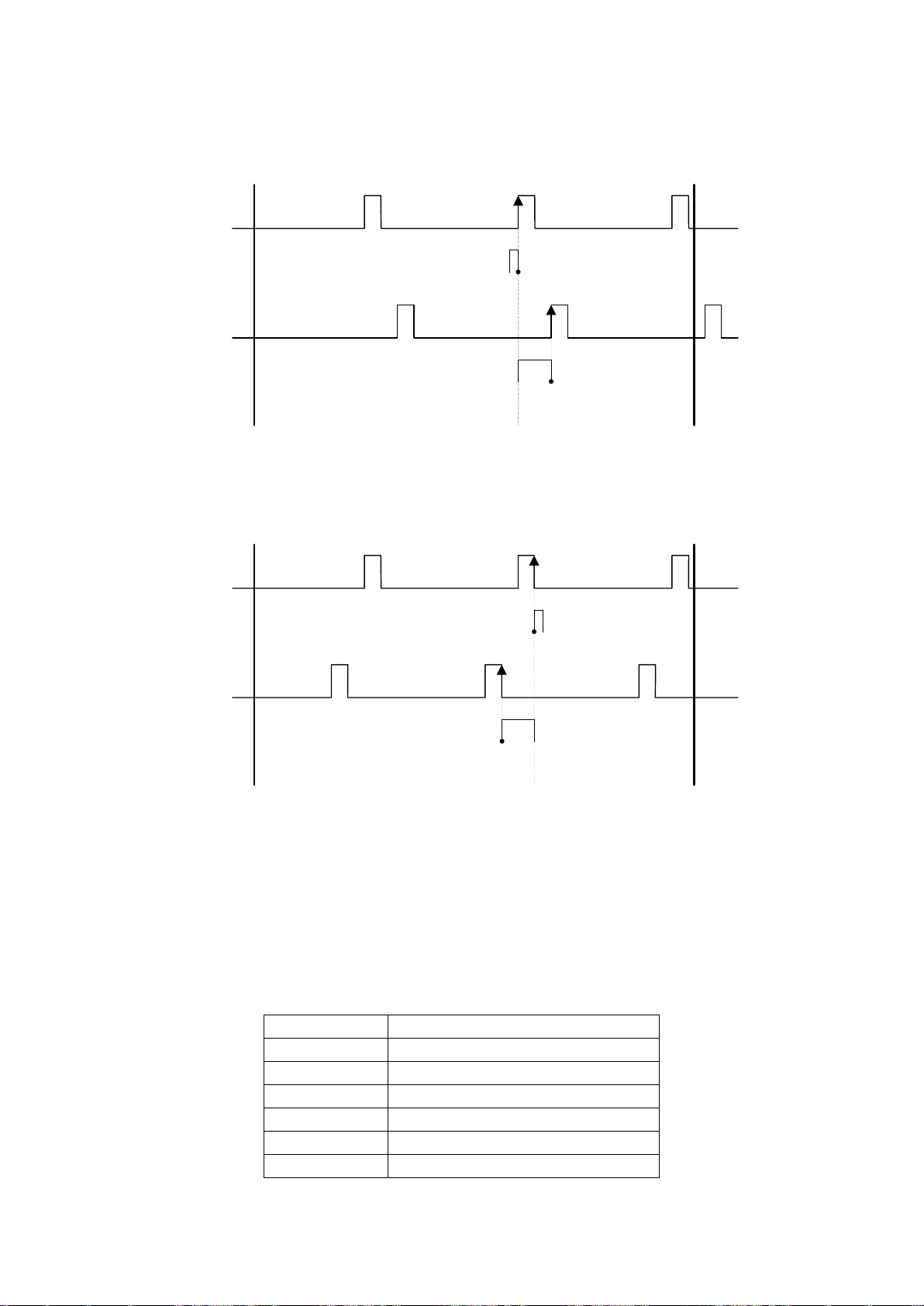
82
【Type7】
CCWLS
<Origin detection
process>
JD
JOG
CWLS
bpoint
cpoint
JD
JOG
ORG
<Excitation timing
detection process>
TIMING
CCWLS
<Origin detection
process>
JD
JOG
CWLS
bpoint
c点
JD
JOG
ORG
<Excitation timing
detection process>
TIMING
○
Detection start position
●
Detection termination position
F Speed
Driving speed(Setting speed)
L Speed
Start-up speed (Setting speed)
JD(JOG)
Detection JOG interval(JD=Lspeed)
LD
Limit detection stop time 300msec
SD
Sensor detection stop time 300msec
After the Type1 is performed, CCW side edge (c point) of TIMING signal is detected.
【Type8】
After the Type2 is performed, CW side edge (c point) of TIMING signal is detected.
【Type9】
【Type10】
【Type11】
【Type12】
After the Type3 is performed, CCW side edge of TIMING signal is detected.
After the Type4 is performed, CW side edge of TIMING signal is detected.
After the Type5 is performed, CCW side edge of TIMING signal is detected.
After the Type6 is performed, CW side edge of TIMING signal is detected.
Page 83
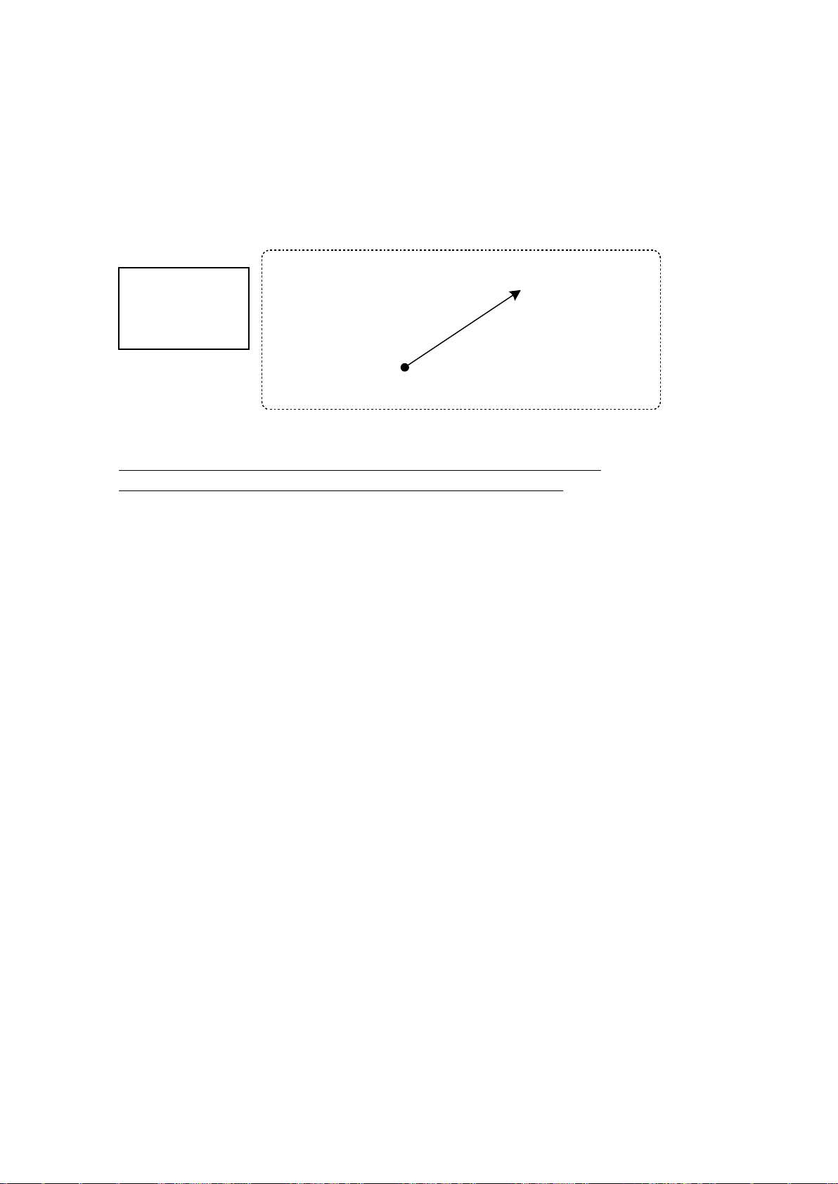
83
3.10 Linear interpolating function
Current point A point(10, 20, 30, 40, 50, 60)
B point(110, 220, 330, 440, 550, 660)
6axes linear
interpolation
一 example
Use linear interpolating function when want to move from current point to specified point as the
shortest distance. Linear interpolation of Max. 6 axes are available at the link connecting. Linear
interpolation is available with control software(DSCONTROL-WIN)or communication command
usage.
However function of linear interpolating is unavailable from handy-terminal.
※Between links interpolating is inaccurate.(2nd and 3rd or 1st and 6th , etc)
That is inferior than same unit axes.(1st and 2nd or 3rd and 4th , etc)
3.10.1 Linear interpolating(Relative value)
Operate from current point to constantly away for each axes.(Relative driving)
【Communication command】
GOLineI _X□Y□Z□U□V□W□
□:+ or - (+:CW specified direction、-:CCW specified direction)
Distance:”PULSe” setted (Unit is as case of current time)
※No driving axis is avoided.(example:GOLineI _X+Z-)。
【Communication command when operate the above example work】
AXIX:PULS _100
AXIY:PULS_200
AXIZ:PULS_300
AXIU:PULS_400
AXIV:PULS_500
AXIW:PULS_600
GOLineI _X+Y+Z+U+V+W+
3.10.2 Linear interpolating(Absolute value)
Operate from current point to point that want to move directly.(Absolute value driving)
【Communication command】
GOLineA_X□_Y□_Z□_U□_V□_W□
□:Specified point(Unit depends on setting unit at the time)
※No driving axes are avoided.(example:GOLineA_X1000_Z-2000)。
【Communication command when operate the above example work】
GOLineA_X110_Y220_Z330_U440_V550_W660
Page 84
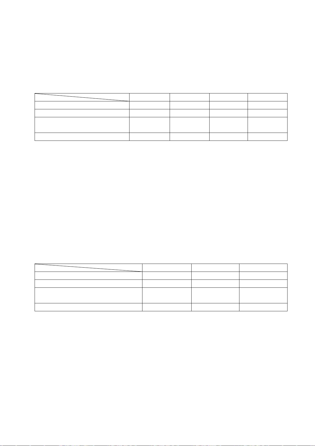
84
3.11 Teaching function
Movement
Registered
Delete
Edit
Controlled I/O(CNT-I/O)
○ × ×
×
Handy terminal DT100
○
○(Each 1 axis)
○(All axes)
○(Each 1 axis)
Controlled software
DSCONTROL-WIN
○
○(All axes)
○(All axes)
△※1
Communication command
○ ○ ○
○
Program edit
Program start
Program stop
Controlled I/O(CNT-I/O)
× ○ ○
Handy terminal DT100
× ○ ○
Controlled software DSCONTROL-WIN
○
(Recommended)
○
○
Communication command
○ ○ ○
This equipment has built-in the teaching function for arbitrary coordinate registration of XY table,
point control simply. The number of points has 64points(00~63), 6 axes are registered on each
points. Movement , registration, delete and edit to teaching point is available to use optional handy
terminal, control software or user program with communication command. Also, specified point and
movement are available for only PLC, I/O control by using controlled I/O (CNT-I/O).
※1 Teaching data (tdf file) that is edited by text editor, display on DSCONTROL-WIN, then, transfer
(writing).
Refer details as shown bellows:
Example teaching function ⇒2.2.1paragraph
Operated by controlled I/O(CNT-I/O) ⇒3.4.2paragraph
Operated by handy terminal ⇒4.1.4.3paragraph
Operated by controlled software DSCONTROL-WIN ⇒4.2.4paragraph
Operated by communication command ⇒4.3.5.2paragraph(14)、4.3.5.6paragraph
(3)
3.12 Program function
This equipment is stand-alone and has built-in the program function that the number of step is
each 100, total 8 for controlled general I/O and easy stage driving.
Refer details as bellows.:
Example teaching function ⇒2.2.2paragraph, 2.2.3paragraph
Operated by controlled I/O(CNT-I/O) ⇒3.4.2paragraph
Operated by handy terminal ⇒4.1.4.2paragraph
Operated by controlled software DSCONTROL-WIN ⇒4.2.5paragraph
Operated by communication command ⇒4.3.6paragraph
Page 85
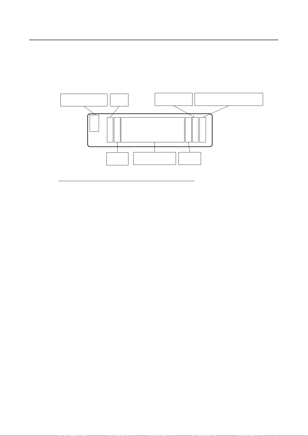
85
4.Operation and Control method
C X 12345678p<0
Y-98765.432u>1
Operation mode Axis
Code
Current position
Status
Unit
Speed table number
4.1 Operation by the handy terminal
4.1.1 Initial screen
Connect handy terminal DT100(MISUMI Type: HDT100) and power on, display initial screen as
below(Continue Mode)in 5 seconds.
※Current position of all axes might be 0 when power on.
<Display operation mode>
Display each operation mode
C (CNT): Continue Mode(Stage drives during press arrow key)
S (STP): Step Mode(Stage drives constantly by pressing arrow key)
A (ABS): Absolute Mode(Stage drives to specified point by pressing arrow key)
O (ORG): Origin Mode(Start to origin return by pressing arrow key)
H (HOM): Home Mode(Stage drives to home position by pressing arrow key)
R: Remote Mode
※”R”(Remote Mode) displays only receive the command from external interface. Only accept
STOP key and JOG key.
<Axis>
Display axis that available controlled(No Link:XY、Link Connecting(2units): XY,ZU、Link Connecting
(3units): XY,ZU,VW)。
<Code>
Display unit at the current point(No display ”+”distance)
<Current point>
Display the current point( effective digit 8 digit, Except dot)
<Unit>
Set up by parameter. Display(p:pulse, u:μm, m:mm, d:deg, r:mrad)
<Status>
Display the axis condition
> : Machine limit +(CW)side is under detection
< : Machine limit -(CCW)side is under detection
■ : Machine limit both +(CW)and -(CCW)side are under detection(No connect to stage)
] : Software limit +(CW)side is under detection
[ : Software limit -(CCW)side is under detection
* : Machine origin point is under stop by origin return
H : Move to position and under stop by home position return
note)Machine limit display is came first when machine limit and soft limit are detected.
<Speed table number>
Display speed table No(0~9)
Page 86
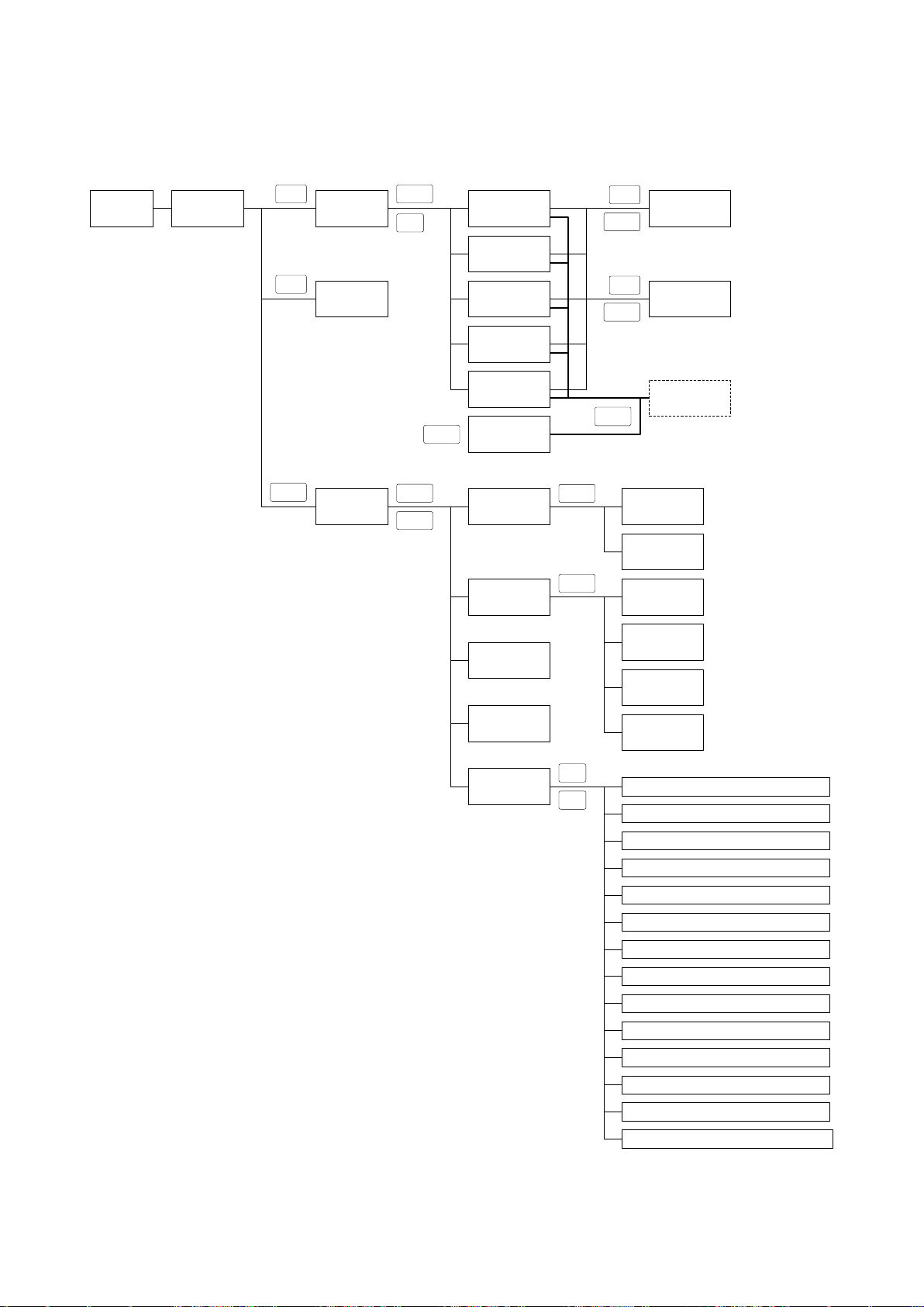
86
4.1.2 Transition mode
POWER ON
Jog
Initial screen
(CNT Mode)
Select driving
mode
Enter
CNT Mode
(Continuous
drive)
STP Mode
(Step driving)
ABS Mode
(Absolute driving)
ORG Mode
(Origin return)
HOME Mode
(Return t )
REMOTE Mode
(Remote
handring)
Jog
Axis select
XY, ZU, VW
Link
Speed table
select
SPD
Enter
ESC
Change current
value
POS
Enter
Stop all axes
STOP
Menu select
Menu
Enter
Menu
PRG Mode
(Program driving)
TCH Mode
(Teaching mode
select)
Enter
PRG_RUN
(Program run)
PRG_STEP
(Program step
run)
Enter
TCH_MOV
(Move teaching
point)
TCH_SET
(Return teaching
point)
TCH_DEL
(Delete teaching
point)
TCH_EDT
(Edit teaching
point)
IN
(General Input
monitor)
OUT
(General output
set-up)
PRM
(Parameter
set-up)
1.Pulse(STP):Set up step distance
2.Pulse(ABS):Set up absolute driving position
3.Speed Table:Set up speed table
4.Unit Set:Set up units and division number
5.Software Limit:Set up software limit
6.Home Position:Set up homeposition
7.Origin Type:Set up zero return type
8.Current Down:Set up current down
9.Limit Sensor:Set up limit sensor logic
10.Origin:Set up ORG sensor logic
11.Near Origin:Set up NORG sensor logic
12.Drive Direction:Set up motor direction
13.Stop Type:Set up motor stop
14.Zero Reset:Set up origin return reset
↓
↑
Handy terminal DT100 Transition mode as bellows.:
Page 87
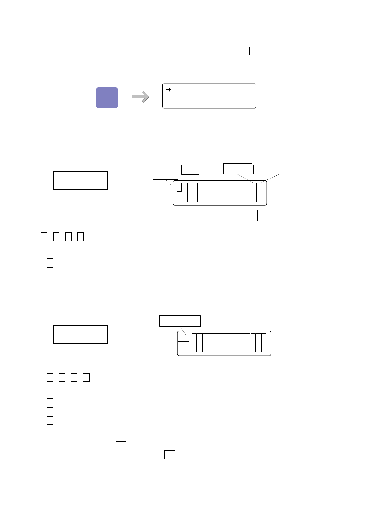
87
4.1.3 Driving mode select(JOG KEY)
C N T S T P O R G H OM
A B S
Jog
7
C X 1 2 3 4 5 6 7 8 p<0
Y-98 7 6 5 . 4 3 2 u>1
Operation
mode
Axis
Code
Current
position
Status
Unit
Speed table number
CNT Mode
S X 1 2 3 4 5 6 7 8 p<0
Y-98 7 6 5 . 4 3 2 u>1
Operation mode
STP Mode
Select each driving mode when each axis operation stop. Press Jog key, it start to display driving
mode select. Select the function by using the arrow key and press ENTER key, then move to each
driving mode.
4.1.3.1 Continuous driving mode(CNT:Continue Mode)
Display as bellows by selected CNT.
←、→、↑、↓ during press any key, drive with setting each parameter.
← key: X(Z,V) axis drive to -(CCW)
→ key: X(Z,V) axis drive to +(CW)
↑ key: Y(U,W) axis drive to +(CW)
↓ key: Y(U,W) axis drive to -(CCW)
4.1.3.2 Uniform pulse driving mode(STP: Step Mode)
Select STP, display as bellows.:
←、→、↑、↓ press any key, start to drive uniform pulse in each parameter.
← key: X(Z,V)axis drive to -(CCW)
→ key: X(Z,V)axis drive to +(CW)
↑ key: Y(U,W)axis drive to +(CW)
↓ key: Y(U,W)axis drive to -(CCW)
STOP key:Stop all axes
* Press shortcut key(Set key)at the step mode, display「Set up uniform pulse distance」.
(Return to step mode screen with Set key)
Page 88
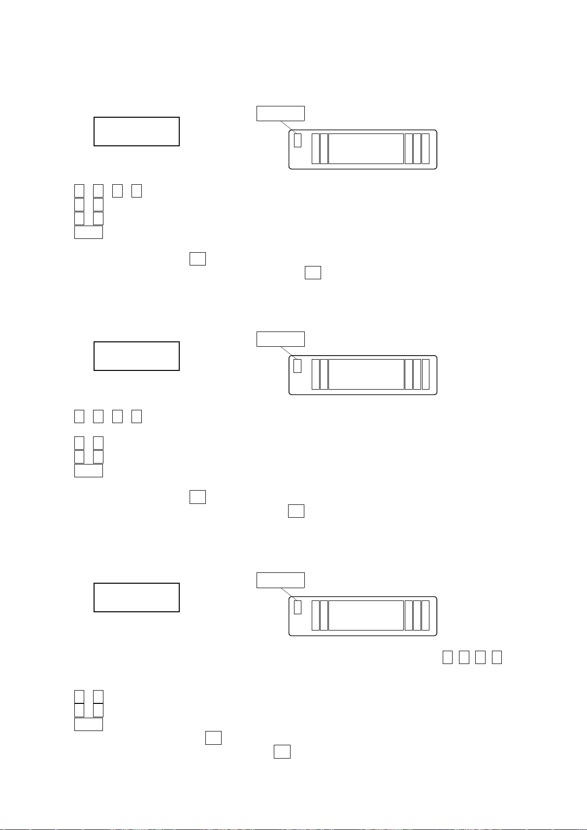
88
4.1.3.3 Absolute value driving mode(ABS: Absolute Mode)
A X 12345678p<0
Y-98765.432u>1
Operation mode
ABS mode
O X 12345678p<0
Y-98765.432u>1
Operation mode
ORG mode
H X 12345678p<0
Y-98765.432u>1
Operation mode
HOM mode
Display as below when selects ABS.
←、→、↑、↓ press any key, start to drive in each parameter
←、→ key: X(Z,V)axis drive to setting position
↑、↓ key: Y(U,W)axis drive to setting position
STOP key : Stop all axes
* Press shortcut key(Set key), display 「Set up absolute value driving position」
(Return to absolute driving mode screen with Set key)
4.1.3.4 Origin return mode(ORG: Origin Mode)
Display as below when selects ORG.
←、→、↑、↓ press any key, start origin return at “Origin Type” of parameter.
After origin return finished , display“*” at “status” of main screen.
←、→ key: X(Z,V)axis return to origin
↑、↓ key: Y(U,W)axis return to origin
STOP key: Stop all axes
* Press shortcut key(Set key), display「Set up origin return type」
(Return to origin return mode screen with Set key)
4.1.3.5 Home position return mode(HOM:HOME)
Display as below when selects HOM.
Move the position that set by “Home Position”of parameter when press any key←、→、↑、↓ After
home position return finished, display “H”at “status” of main screen.
←、→ key: X(Z,V)axis return to home position
↑、↓ key: Y(U,W)axis return to home position
STOP key : Stop all axes
※ Press shortcut key,(Set key), display「Set up home position」
(Return to return mode screen with Set key)
Page 89
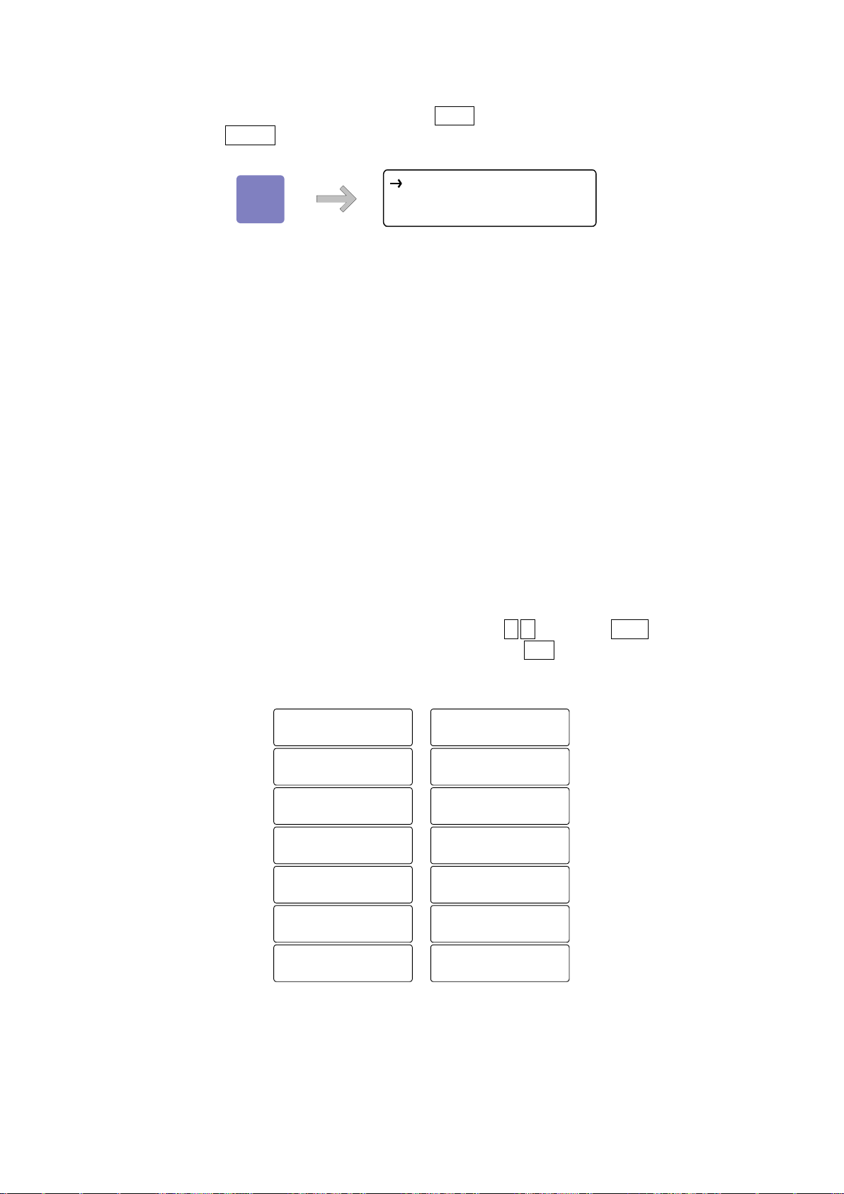
89
4.1.4 Menu select(Menu key)
8.
Cu r ren t D own
9.
Li m it S e n sor
10.
Or i g in
11.
Ne a r Or i g in
12.
Dr i v e Di r ect i o n
13.
S t o p Ty p e
14.
Ze r o Re s e t
1.
P uls e (ST P )
2.
P uls e (AB S )
3.
Sp e ed T a b le
4.
U n i t Se t
5.
So f t wa r e L imi t
6.
Ho m e P os i t io n
7.
Or i gin T y pe
P R M P R G T C H
I N O U T
Menu
8
Select each menu at not <Remote Mode>. Press Menu key, display as bellows. Show each mode
screen when press ENTER key after select mode with arrow key.
4.1.4.1 Parameter mode(PRM)
Allow parameter setting when select PRM.
① Pulse(STP) : Set up uniform pulse distance
② Pulse(ABS) : Set up absolute value driving position
③ Speed Table : Set up speed table
④ Unit Set : Unit(UT)、Pulse distance per 1 step(SD)、Set up division number of driver(DR)
(Distance(RE) per 1 pulse automatically calculated)
⑤ Software Limit : Set up software limit
⑥ Home Position : Set up home position
⑦ Origin Type : Set up origin return type
⑧ Current Down : Set up current down
⑨ Limit Sensor : Set up limit sensor logic
⑩ Origin : Set up origin sensor logic
⑪ Near Origin : Set up nearby origin sensor logic
⑫ Drive Direction : Set up driving direction
⑬ Stop Type : Set up stopping
⑭ Zero Reset : Set up 0 reset at return to origin
14 parameter setting screen might be changed in order by ↑,↓ key. Press Enter key, display each
parameter setting screen. Return to menu select screen with ESC key.
【List of Parameter selection】
Page 90
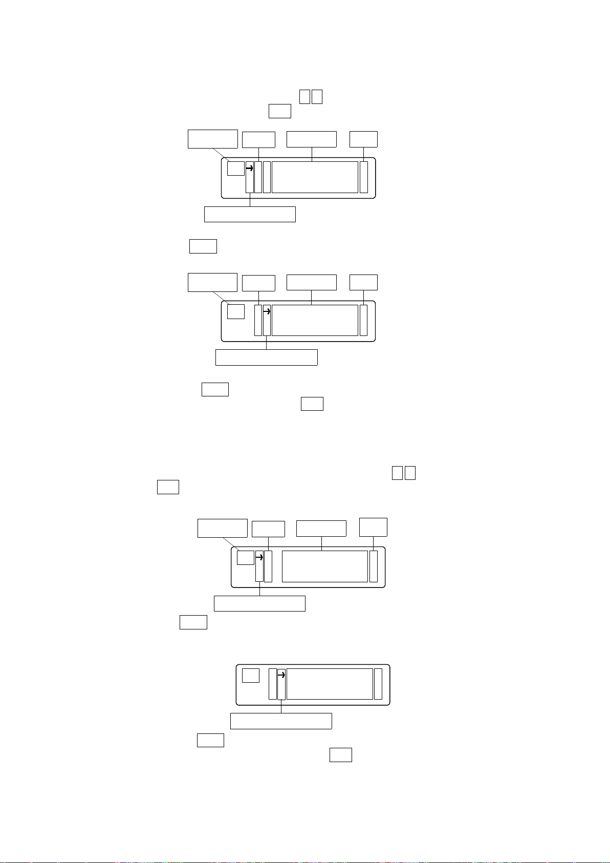
90
①Pulse(STP) (Uniform pulse driving, Set up distance value)
P S X 1 0 0 . 0u
Y 1000d
Parametor
Axis
Setting data unit
Cursor position at select axis
P S X 1 0 0 . 0 u
Y 1000d
Parameter
Axis
Setting data unit
Cursor position at input data
P A X 2 0 0 . 0 u
Y - 2000d
Parameter
Axis
Setting data
Unit
Cursor position at select axis
P A X 2 0 0 .0u
Y - 2000d
Carsor position at input data
Set up distance at uniform pulse driving(Step Mode)
Select“Pulse(STP)”, shows as below.: Press ↑,↓ key, select a setting axis.
Return to parameter select screen with ESC key.
After axis selected, press Enter key, display the cursor on left lateral of setting data. Can be input the
setting data with numeric keypad.
After setting finished, press Enter key, be moved the cursor on left lateral and input any other axis.
※During input the setting data, continue to press ESC key(1 sec.), might be return to select the setting
axis without input setting data.
②Pulse(ABS) (Set up absolute position)
Select driving position at absolute position driving(ABS Mode)
Display as below with “Pulse(ABS)”, Select setting axis with ↑,↓ key. Return to parameter
select screen with ESC key.
After axis selected, press Enter key, display the cursor on left lateral. Can be input the setting data with
numeric keypad.
※ “+”no displayed
After setting finished, press Enter key, be moved the cursor on left-lateral and input any other axis
※During input the setting data, continue to press ESC key(1 sec.), might be return to select the
setting axis without input setting data.
Page 91
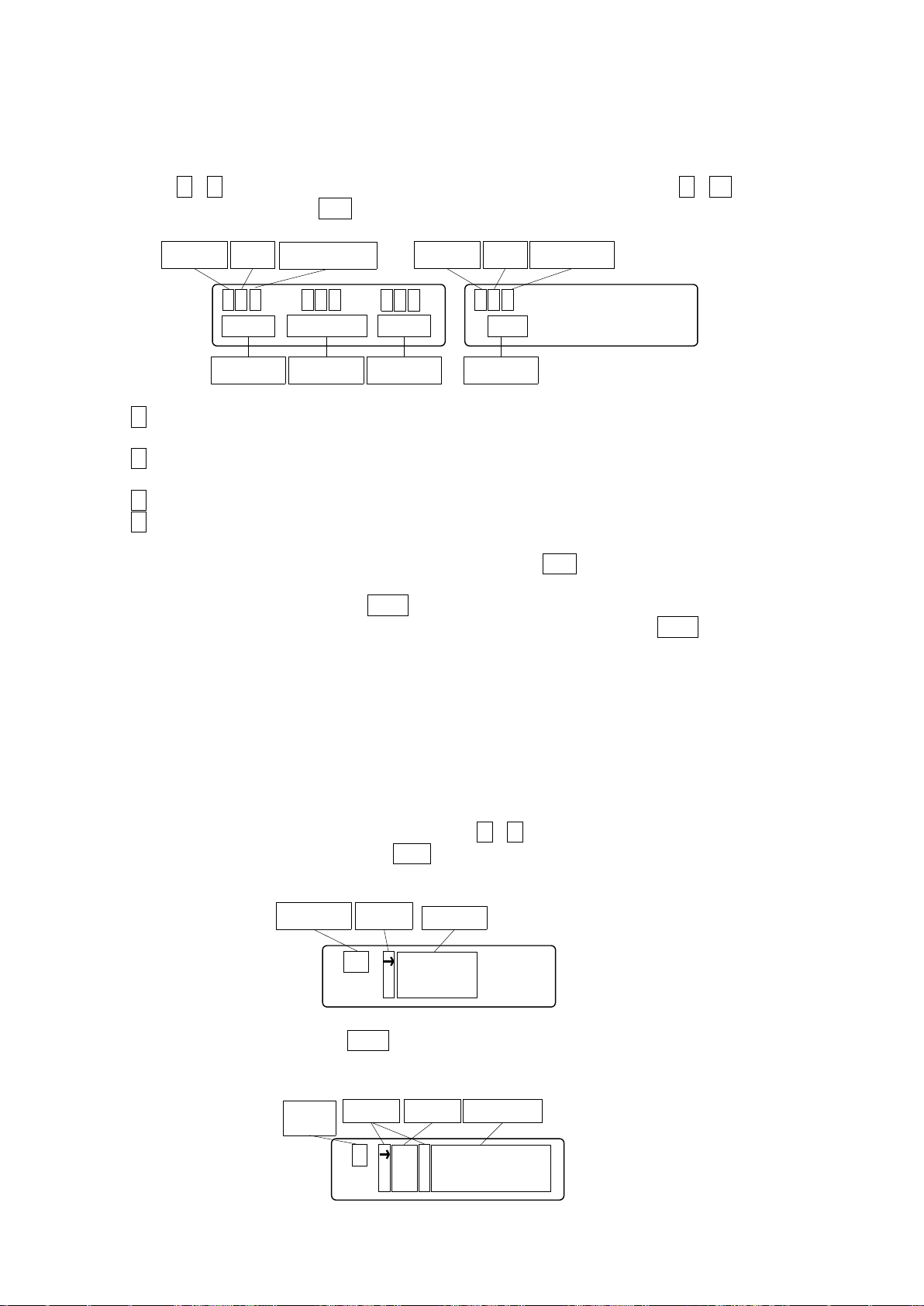
91
US X - a x i s
Y - a x i s
Parametor Carsor
Setting axis
X UN m(mm)
ST 0.001
Setting
axis
Cursor Setting dataItem
*L0 F0 R 0
1 0 1 0 1
Data Data
Cursor
Data
Item
Table Number
S0
1 0
Cursor
Data
Item Table Number
③Speed Table(Set up speed table)
Set up starting speed(L), driving speed(F), acceleration and deceleration rate(R ) and S acceleration
and deceleration rate(%). Display each (L)(R)(S) setting data and speed table number when select
“Speed Table” shown as below.: At this time, “*” shows on left-lateral of setting item. Be moved
“*”with ←、→ key , then select(R)or (S). Select speed table number with ↑、↓ key. Return to
parameter select screen with ESC key
← key: Move the cursor(*)to the left. Case of cursor is in left-lateral S rate(S), change the screen
and display the acceleration and deceleration rate.(See the above)
→ key: Move the cursor(*)to the right. Case of cursor is in left-lateral (R), change the screen and
display the S acceleration and deceleration rate(S). (See the above)
↑キー: Speed Table Number change to order 9→8→…→1→0
↓キー: Speed Table Number change to order0→1→…→8→9
※ Return to parameter select screen if press ESC during select the Speed Table or
setting item
After moved by arrow key, press Enter key and then change to →. Possible to input with numeric
keypad. (* Displayed in continuous pressing ESC key). After input, press Enter key, be confirmed
setting value and change → to “*”.
④Unit Set(Set up units and division number)
Set up the unit, the distance per pulse at full step and division number of driver.
This set up shows distance per pulse,
(Distance per pulse at the full step)÷(Division number of driver)
automatically calculated.
Display cursor when select “Unit Set”, jump to setting screen that set units.
Move the cursor to left-lateral of axis that set with ↑、↓key.
Return to parameter select screen with ESC key.
After select the setting axis, press Enter key, “Unit(UN)”and “Distance per 1 pulse at the full step”
(ST)of axis that selected as bellows.:
Page 92
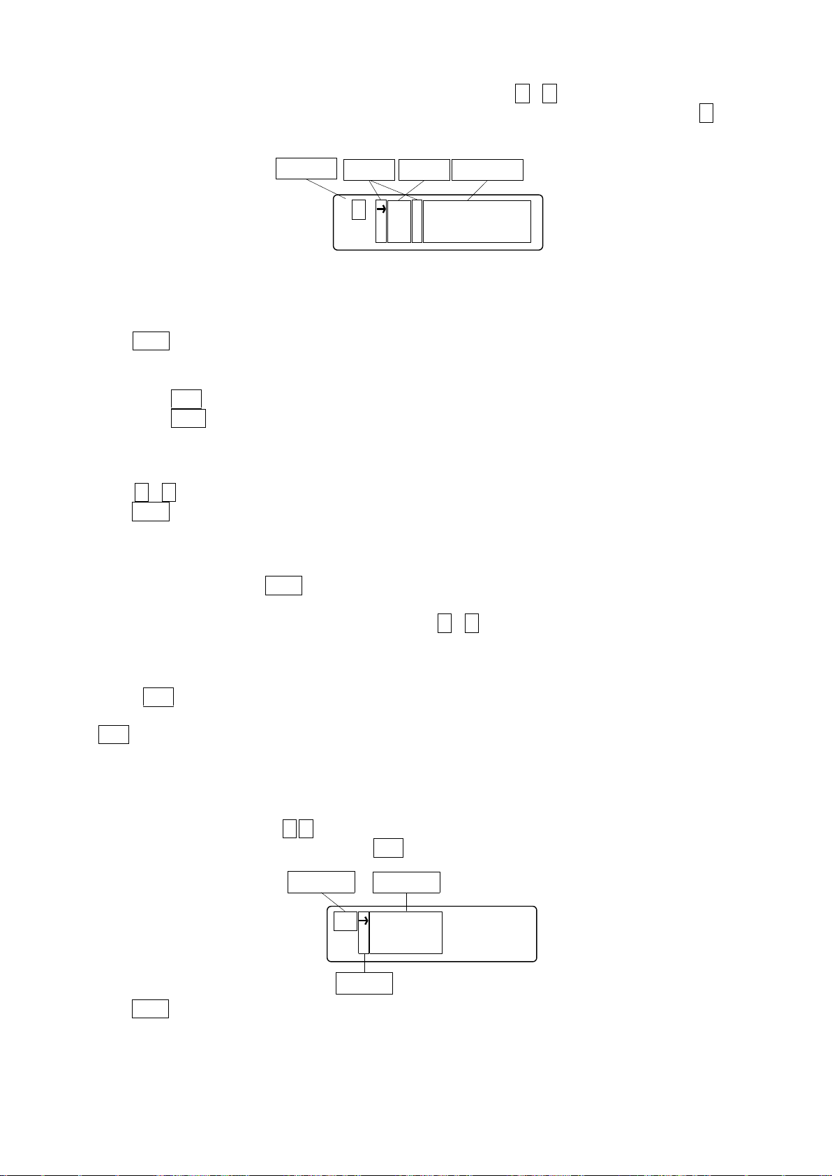
92
Move cursor to the side of setting item that want to be set with ↑、↓key.
X DR 1/2
RE 0.0005
Setting axis
Carsor Setting dataItem
S L X-a x i s
Y-a x i s
Parametor
Selection axis
Cursor
Shows “distance per 1pulse (RE) and “Set up drivers division number (DR)” when press ↓key
for 2 times.
* RE
(Distance per 1 pulse at the full step)÷(Division number of driver)
Automatically calculated
Press Enterkey when move the cursor to setting item that want to be setting. Then, carsor move to
left-lateral of setting data that selected, available to input the setting data.
※Press ESC key at the setting item select screen, return to axis selecting screen.
※Press ESC key at the setting data input screen, return to setting item select screen.
<UN>
Set the units
Press ↑、↓ key, then select (p(pulse)/u(um)/m(mm)/d(deg)/r(mrad))
Press Enter key after finished input, return to setting item select screen.
<SD>
Set up the distance per 1 pulse at the full step of motorized stage.
Input setting data with numeric keypad.
After input finished, press Enter key, return to setting item select screen.
<DR>
Set up the division number of motorized driver with ↑、↓ key.
Normal driver → FULL/HALF
Micro step driver → 1/1~1/250
※If press ESC key during input the setting data, return to selection screen of setting item without
setting data.(In case of ST entry screen, (Return to selection screen of setting item with
ESC key continuation press(1 sec))
⑤Software Limit(Set up Software Limit)
Set up valid/invalid and set the coodinate of software limit.
When select the “Software Limit”, display the cursor on left-lateral at the selection screen that
setted software limit. Press ↑,↓ key, select the setting axis.
Return to parameter selection screen with ESC key.
Press Enter key after finished selection of axis. Move to Software Limit setting screen of +(CW) side of
selection axis, then cursor shows on left-lateral
Page 93
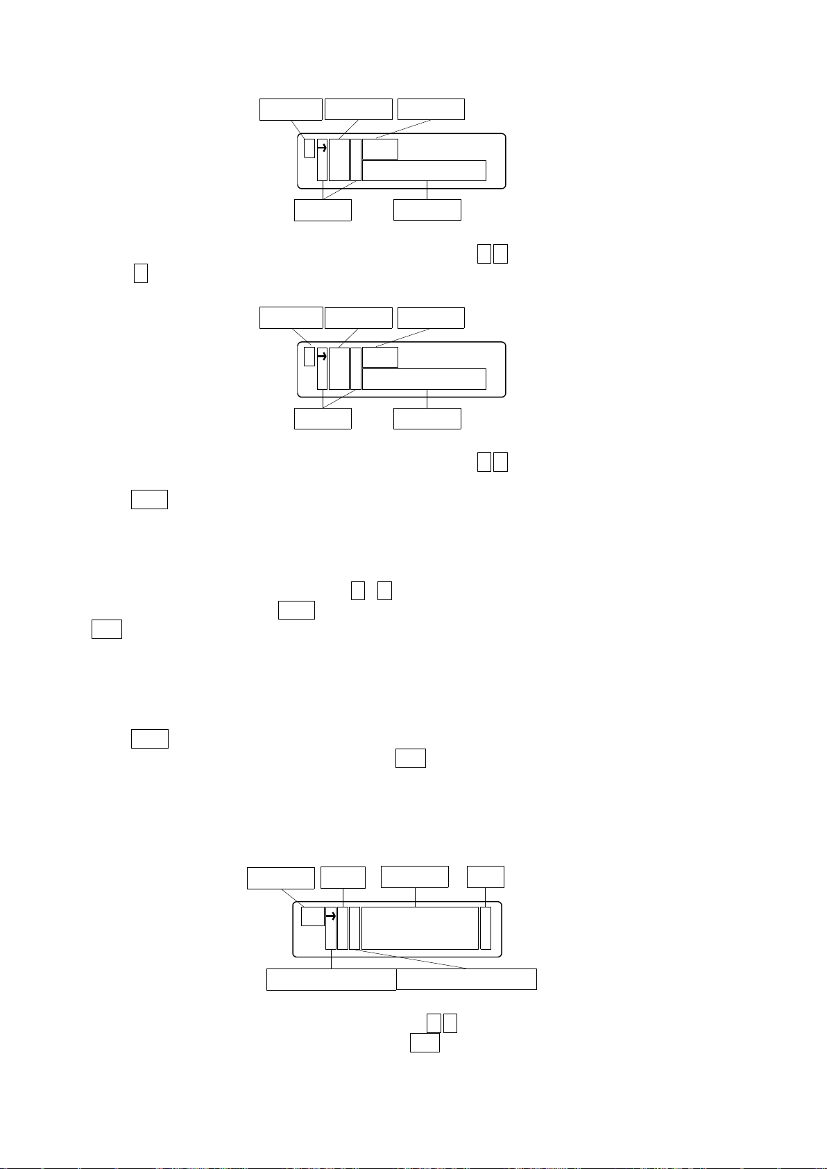
93
X +E OFF
+L 10000p
Setting axis
Setting data
Cursor
Setting item
Setting data
X -E OFF
-L 10000p
Setting axis
Setting data
Cursor
Setting Item
Setting data
H P X 0.00 0 5 0 0 0 m
Y - 5 . 0 0 0 u
Parametor
Axis
Setting data Unit
Cursol position f or selected axis
Cursol position for data input
Move cursor to the left-lateral of setting item that set with ↑,↓ key.
Press ↓ key 2 times, display Software Limit setting screen of (CCW) side as bellows.:
Move cursor to the left-lateral of setting item that set with ↑,↓ key.
Press Enter key when move the cursor to setting item that want to be setting. Then, Cursor move to
left-lateral of setting data that selected, available to input the setting data.
<+E,-E>
Set up Software Limit(CW,CCW distance)valid/invalid.
Select Software Limit valid/invalid with ↑、↓key.
After selection, be fixed with Enter key and return to selection screen. Return to selection screen with
ESC key.
<+L,-L>
Set up the coodinate(CW,CCW direction).
Can be changed with numeric keypad.
Press Enter key after finished input, return to setting item select screen.
Return to selection screen of setting item with ESC key continuation press(1 sec).
⑥Home Position(Set up Home position)
Set up Home position for each axis.
When select the “Home Position”, to be Home position setting screen. Display the cursor on left
lateral of setting axis.
Move cursor to the left-lateral of axis that set with ↑,↓ key.
※Return to parameter selection screen with ESC key .
Page 94
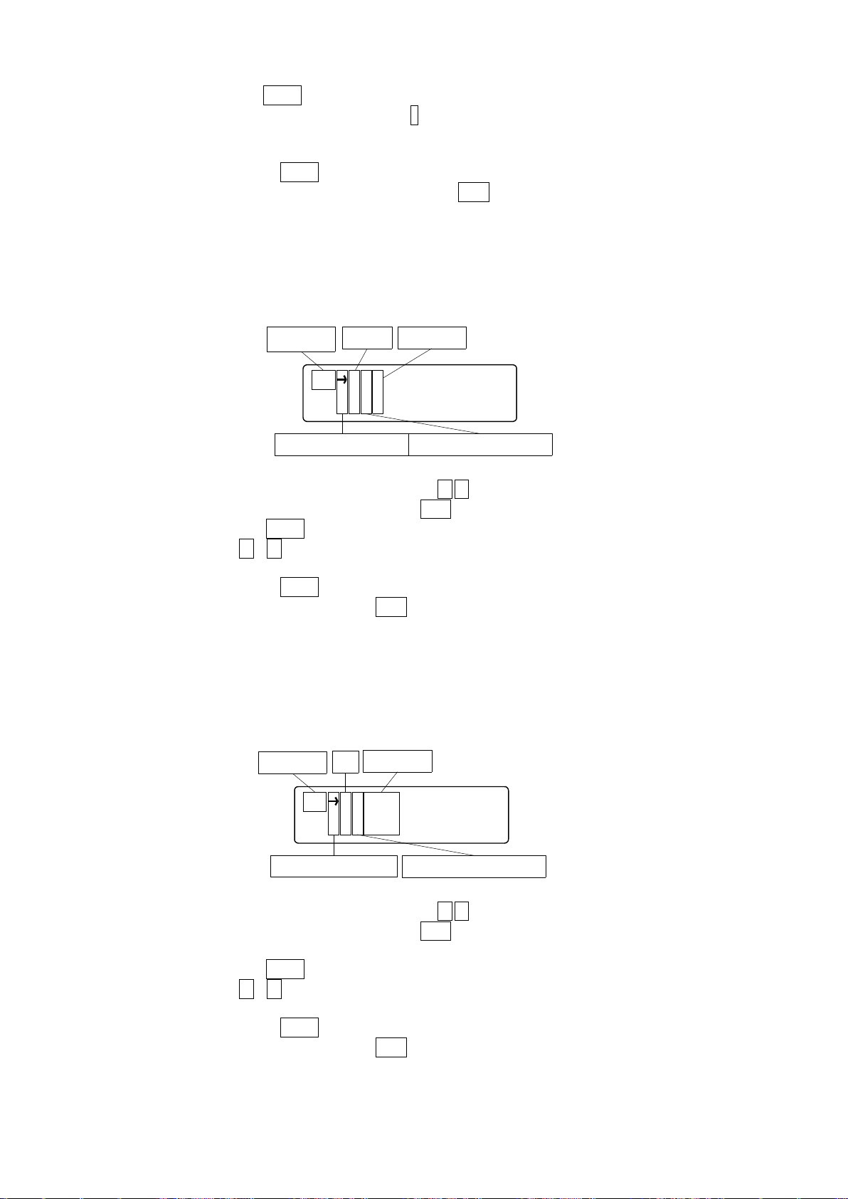
94
After axis selected, press Enter key, display the cursor on left lateral of setting data. Can be input the
O T X 0
Y 1
Parameter
Axis
Setting data
Cursol position for selected axis Cursol position for data input
C D X O N
Y O F F
Parametor
Axis
Setting data
Cursol position for selected axis
Cursol position for input data
setting data with numeric keypad. Please input –key first when input the code.
※ “+”no displayed
After setting finished, press Enter key, be moved the cursor on left-lateral and input any other axis
※During input the setting data, continue to press ESC key(1 sec.), might be return to select the
setting axis without input setting data.
⑦Origin Type(Set up Origin return type)
Set up each axis origin return type.
When select the “Origin Type”, to be Origin Type setting screen. Display the cursor on left lateral of
setting axis.
Move cursor to the left-lateral of axis that set with ↑,↓ key.
※Return to parameter selection screen with ESC key.
After axis selected, press Enter key, display the cursor on left-lateral of setting data, and then input
the setting data with ↑、↓key.
After setting finished, press Enter key, be moved the cursor on left-lateral and input any other axis
※During input the setting data, press ESC key, might be return to select the setting axis without
input setting data.
⑧Current Down(Current Down Control Setting)
Set up each axis Current Down Control Setting.
When select the “Current Down”, to be Current down setting screen. Display the cursor on left
lateral of setting axis.
Move cursor to the left-lateral of axis that set with ↑,↓ key.
※Return to parameter selection screen with ESC key.
After axis selected, press Enter key, display the cursor on left-lateral of setting data, and then input
the setting data with ↑、↓key.
After setting finished, press Enter key, be moved the cursor on left-lateral and input any other axis
※During input the setting data, press ESC key, might be return to select the setting axis without
input setting data.
Page 95
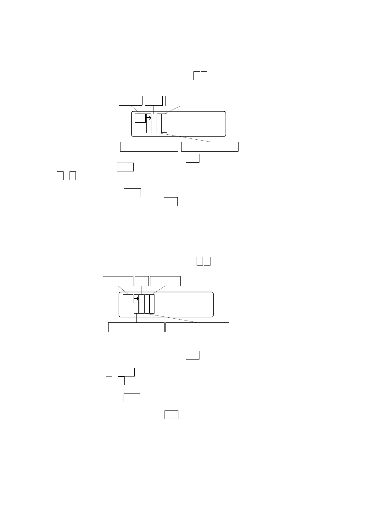
95
LS X B
Y B
Parametor
Axis
Setting data
Cursol position for selected axis Cursol position for input data
OR X B
Y B
Parametor Axis
Setting data
Cursol position for selected axis Cursol position for input data
⑨Limit Sensor(Limit Sensor Logic Setting)
Set up each axis Limit Sensor Logic Setting.
When select the “Limit Sensor”, to be Limit Sensor Logic setting screen. Display the cursor on left
lateral of setting axis
Move cursor to the left-lateral of axis that set with ↑,↓ key.
※Return to parameter selection screen with ESC key
After axis selected, press Enter key, display the cursor on left-lateral, and then input the setting data
with ↑、↓key.
After setting finished, press Enter key, be moved the cursor on left-lateral and input any other axis
※During input the setting data, press ESC key), might be return to select the setting axis without
input setting data.
⑩Origin(Origin Sensor Logic Setting)
Set up each axis Origin Sensor Logic Setting.
When select the “Origin”, to be Origin Sensor Logic setting screen. Display the cursor on left lateral of
setting axis.
Move cursor to the left-lateral of axis that set with ↑,↓ key.
※Return to parameter selection screen with ESC key.
After axis selected, press Enter key, display the cursor on left-lateral of setting data, and then input
the setting data with ↑、↓key.
After setting finished, press Enter key, be moved the cursor on left-lateral of axis and input any other
axis.
※During input the setting data, press ESC key, might be return to select the setting axis without
input setting data.
Page 96
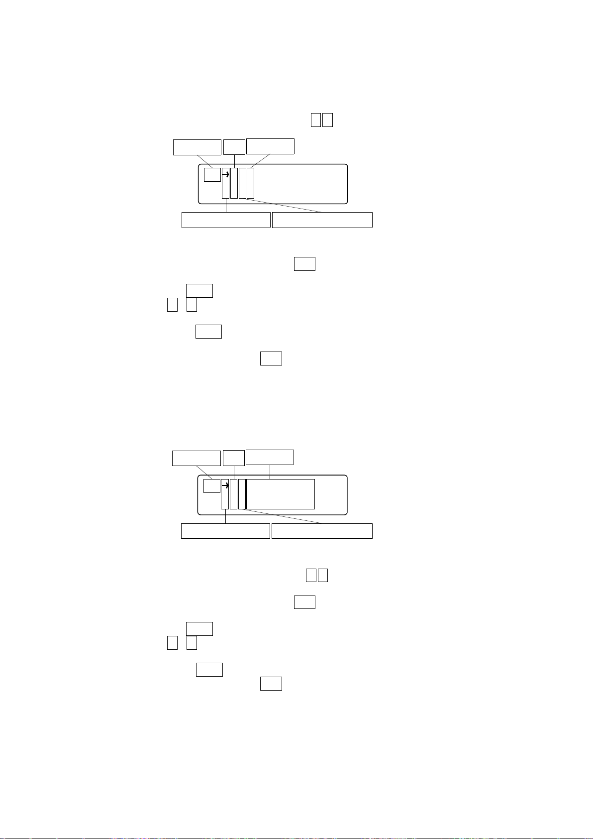
96
⑪Near Origin(Near Origin Sensor Logic setting)
NO X B
Y B
Parametor
Axis
Setting data
Cursol position for selected axis Cursol position for input data
D D X Po s i t i v e
Y Ne g a t i v e
Parametor
Axis
Setting data
Cursol position selected axis Cursol position input data
Set up each axis Near Origin Sensor Logic Setting
When select the “Near Origin”, to be Near Origin Sensor Logic setting screen. Display the cursor on
left lateral of setting axis.
Move cursor to the left-lateral of axis that set with ↑,↓ key.
※Return to parameter selection screen with ESC key.
After axis selected, press Enter key, display the cursor on left-lateral of setting data, and then input
the setting data with ↑、↓key.
After setting finished, press Enter key, be moved the cursor on left-lateral of axis and input any other
axis.
※During input the setting data, press ESC key, might be return to select the setting axis without
input setting data.
⑫Drive Direction(Motor Driving Direction)
Set up each axis Motor Driving Direction Setting.
When select the “Driving Direction”, to be Motor Driving Direction setting screen. Display the cursor
on left lateral of setting axis.
Move cursor to the left-lateral of axis that set with ↑,↓ key.
※Return to parameter selection screen with ESC key.
After axis selected, press Enter key, display the cursor on left-lateral of setting data, and then input
the setting data with ↑、↓key.
After setting finished, press Enter key, be moved the cursor on left-lateral and input any other axis
※During input the setting data, press ESC key, might be return to select the setting axis without
input setting data.
Page 97
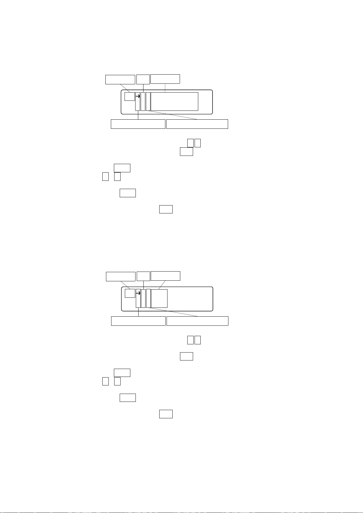
97
⑬Stop Type(Motor Stop Setting)
S T X Fa s t - S t o p
Y Sl o w - S t o p
Parametor
Axis
Setting data
Cursol position for selected axis Cursol position for input data
Z R X Ye s
Y No
Parametor
Axis
Setting data
Cursol position for selected axis Cursol potion for input data
Set up each axis Motor Stop Setting
When select the “Stop Type”, to be Motor Stop setting screen. Display the cursor on left lateral of
setting axis.
Move cursor to the left-lateral of axis that set with ↑,↓ key.
※Return to parameter selection screen with ESC key。
After axis selected, press Enter key, display the cursor on left-lateral of setting data, and then input
the setting data with ↑、↓key
After setting finished, press Enter key, be moved the cursor on left-lateral of axis and input any other
axis.
※During input the setting data, press ESC key, might be return to select the setting axis without
input setteing data.
⑭Zero Reset(Count Zero Reset Setting at Origin Return)
Set up each axis Count Zero Reset Setting
When select the “Zero Reset”, to be Count Zero Reset setting screen. Display the cursor on left
lateral of setting axis.
Move cursor to the left-lateral of axis that set with ↑,↓ key
※Return to parameter selection screen with ESC key.
After axis selected, press Enter key, display the cursor on left-lateral of setting data, and then input
the setting data with ↑、↓key.
After setting finished, press Enter key, be moved the cursor on left-lateral of axis and input any other
axis.
※During input the setting data, press ESC key, might be return to select the setting axis without
input setteing data.
Page 98
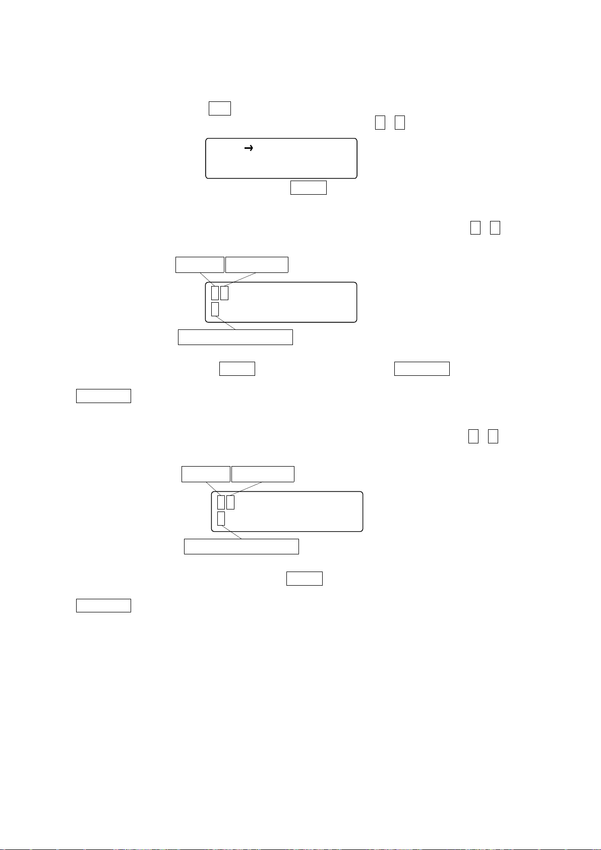
98
4.1.4.2 Program Driving Mode(PRG)
PRG R U N
S T EP
P 0X 1 2 3 4 5 6 7 8 p<0
R Y-98 7 6 5 . 4 3 2 u>1
Driving Mode Program number
Program driving
P 0X 1 2 3 4 5 6 7 8 p<0
S Y-98 7 6 5 . 4 3 2 u>1
Driving mode Program number
Program (STEP) driving
Downloaded from computer program(8Programs(0~7)、100Steps/1Program)is driven and
stopped. If select “PRG”, shows bellows screen and cursor is displayed on left-lateral. Return to
Menu selection screen with ESC key.
Move cursor to the left-lateral that selected driving mode with ↑、↓key.
After select the program driving mode, press ENTER key jump to following each driving screen.
<Select RUN mode(a series of operations)>
Select “RUN”, display the program number. Change the program number with ↑、↓key (Only
display registered program number in 8 programs)
After selected program, press ENTER key display “R”. If press STOP/ESCkey during the drive
Program might be stop. Return to program driving mode selection screen during press
STOP/ESCkey at off-line.
<STEP mode selection>
Select “STEP”, display the program number. Change the program number with ↑、↓key.
After selected program number, each press ENTER key drive the selection program each 1 line.
Display “S” during drive. Return to program driving mode selection screen during press
STOP/ESC key at off-line.
<Registered, change and delete>
Please enter to registered, change and delete in the controlled software(DSCONTROL-WIN)
No work DT100.
Page 99
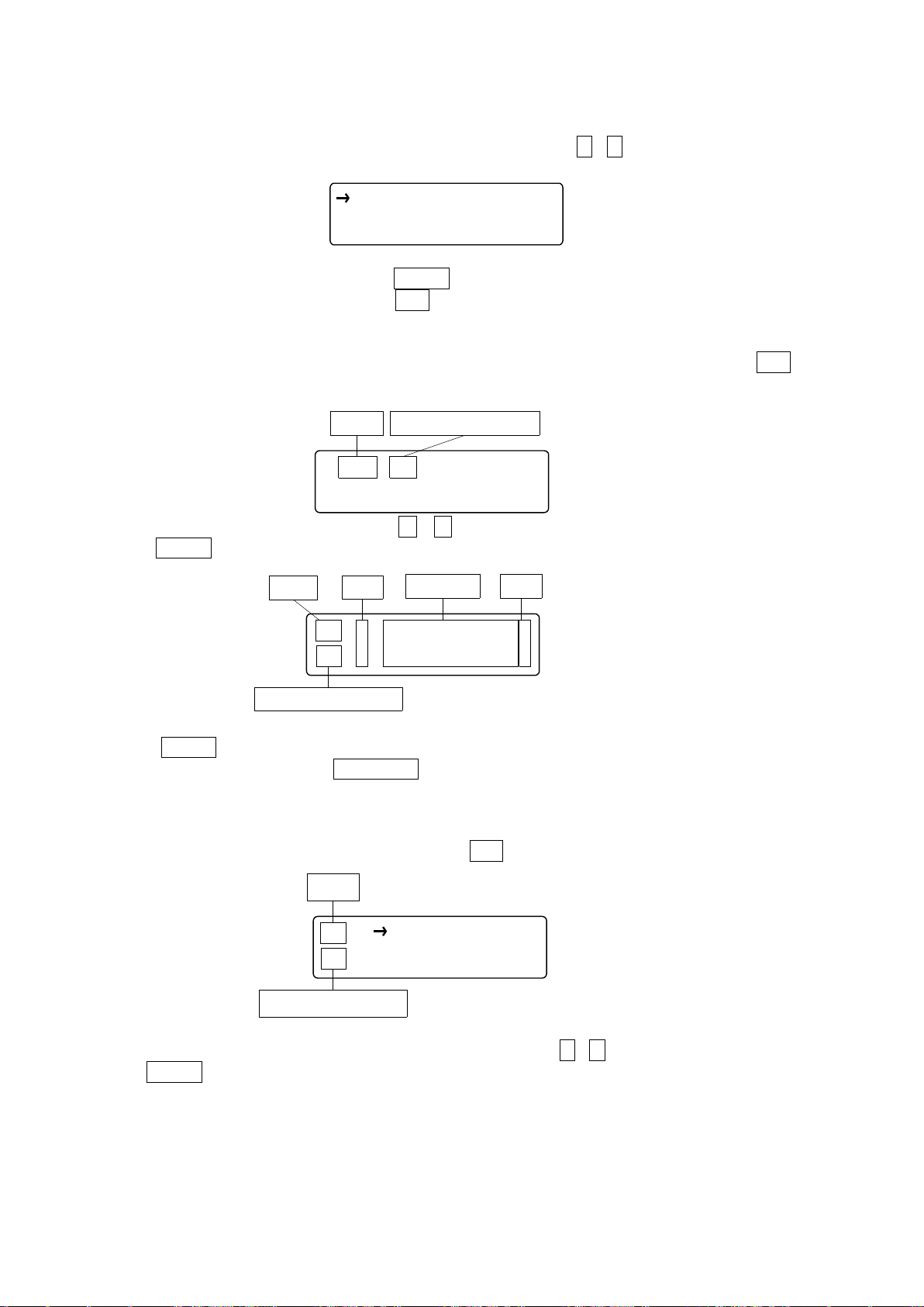
99
4.1.4.3 Teaching mode (TCH)
M OV 00
Mode Teaching point number
M O V S E T D E L E DT
TM X 1000p
00 Y - 0.1234m
Mode
Axis
Setting data Unit
Teaching point number
T S CN T S T P
12
Mode
Teaching point number
If select “TCH”, shows bellows screen and cursor is displayed on left-lateral.
Move cursor to the left-lateral that selected teaching mode with ←、→key.
After select the teaching mode, press ENTER key, jump to following each driving screen.
Return to Menu selection screen with ESC key.
<MOV: Teaching Point Moving>
If select “MOV”, shows bellows screen (Return to teaching mode selection screen with ESC key.)
Change the program number with ↑ 、 ↓ key. Display the teaching point what you want ,
pressENTER key .
Press ENTER key at this screen, start to move to teaching point.(Return to teaching point number
selection screen during press STOP/ESC key at off-line.)
<SET: Teaching point setting>
If select “SET”, shows bellows screen.
Return to teaching mode selection screen with ESC key.
Move cursol to the left-lateral that selected driving mode with ←、→ key.
Press ENTER key, jump to following teaching point number selection screen of each mode.
Page 100
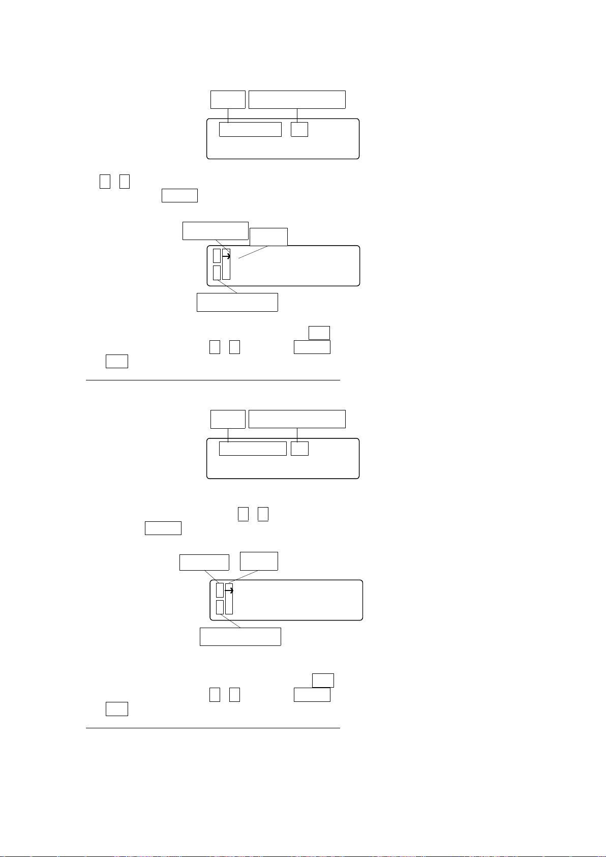
100
(1)CNT
C X 1 2 3 4 5 6 7 8 p<0
T Y-98 7 6 5 . 4 3 2 u>1
Driving mode
Cursol
Teachng Mode
CNT SET 12
Mode
Teaching Point Number
STP SET 12
Mode
Teaching point number
S X 1 2 3 4 5 6 7 8 p<0
T Y-98 7 6 5 . 4 3 2 u>1
Driving Mode
Cursol
Teaching Mode
Use ↑、↓ key, and change the teaching number. (Counted up and down continuously-pressed
over 1sec.) Press ENTER key with displaying teaching number, then jump to following screen.
It is possible to drive Jog with arrow key. Press SET key at the registered position, display cursor.
Select registered axis with ↑、↓ key, press ENTER key, then coordinate registration.
Press ESC key, return to teaching point selection screen.
※ Can be changed speed table during teaching mode.
(2)STP
Change the teaching point with ↑、↓ key,(Counted up and down continuously-pressed over
1sec.). Press ENTER key with displaying teaching number, then jump to following screen.
It is possible to drive STEP with arrow key. Press SET key at the registered position, display cursor.
Select registered axis with ↑、↓ key, press ENTER key, then coordinate registration.
Press ESC key, return to teaching point selection screen.
※ Can be changed speed table during teaching mode.
 Loading...