

Page 1
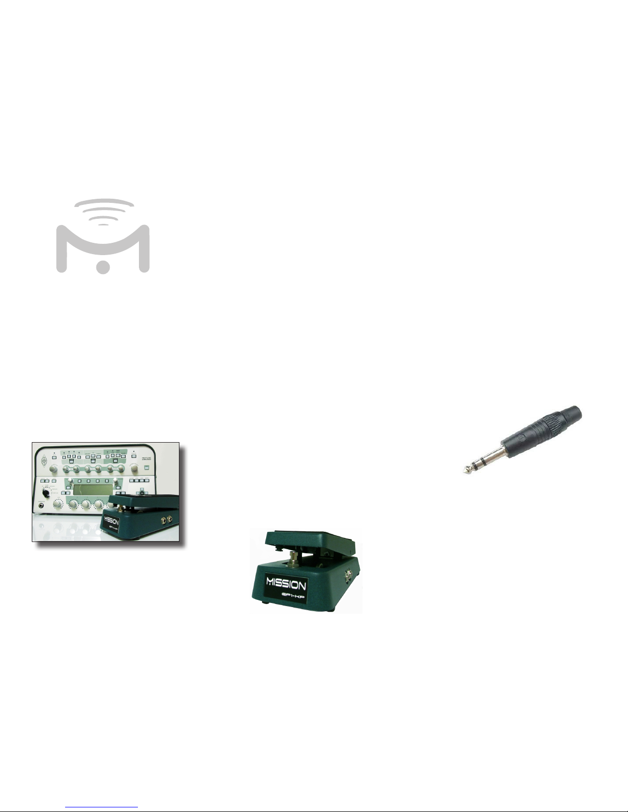
Kemper Profiling Amp
Expression Pedal
1-KP
Ur
Guide
MISSION
ENGINEING
Inoduion
Congratulations on your purchase of the Mission
EP1-KP expression pedal. This product is designed
to be intuitive to setup and operate, and to provide
many years of trouble free service.
However, we recommend that you take a few
moments to read through this User Guide in order
to get the best possible experience with your new
pedal.
ftur
The EP1-KP is an expression pedal designed for
use with the Kemper Profiling Amplifier. It features
Mission’s unique switching expression pedal function
that allows effects to be turned on and off at the
pedal, just like a conventional analog effect. The
pedal is matched to the amplifier to utilize the full
sweep and provide a smooth response with no dead
spots.
The EP1-KP is a passive device and requires no
internal battery or external power source.
ConnEions
The EP1-KP uses two ¼” phone plug outputs marked
OUT1 and OUT2 on the underside of the pedal.
OUT1 is the expression pedal output, and OUT2 is
the footswitch output. Connect OUT1 to switch/
pedal input 1 on the rear panel of the amplifier using
a ¼” TRS-TRS instrument cable, such as the Mission
MCTRS10A cable. TRS stands for Tip, Ring, Sleeve
and is a three-conductor cable. It is sometimes also
called a stereo, or balanced cable (See Figure 1.)
OUT1 requires the use of the correct cable with a
TRS connector at both ends. A mono TS cable such
as a regular guitar cable, and insert cables that have
both TS and TRS plugs, will not work.
Figure 1. shows a TRS connector with the three
conductors separated by the black insulation bands.
The pointed front of the connector is the tip, the
middle band is the ring, and the large conductor at
the rear nearest the plug body is the sleeve.
Use of the internal footswitch is optional. To use the
footswitch, connect OUT2 to switch/pedal input 2
on the rear panel of the amplifier using a standard
mono (TS) ¼” guitar or patch cable.
Figure 1.
Page 2

no
When using the footswitch option, both inputs on
the amplifier are used and the maximum number of
pedals that can be connected via the back panel is
one. If you intend to use another method of turning
effects on an off such as MIDI, auto-detection, or
front panel switches then the switch out can be left
unconnected and you can connect a maximum of two
EP1-KP pedals to the amplifier.
ecifitions
Electrical Specifications
Potentiometer
Internal resistance - 10K Ohm
Taper – Linear
Polarity – Tip to wiper
Function – Voltage Divider
Usage rating > 1M cycles
Dimensions
Base length at longest point - 9.9”
Base width at widest point - 4.0”
Height at highest point including feet - 3.25”
Pedal length - 8.7”
Pedal width at widest point - 3.0”
Pedal width at narrowest point - 2.3”
Weight - 3.5lbs
Mission Enginring Inc.
www.missionengineering.com
info@mission-engineering.com
©Mission Engineering Inc. 2012. All rights reserved. EP1-KP is
a Trademark of Mission Engineering Inc. Trademarks, registered
trademarks, product names, logos and other materials are the
property of their respective owners.
Saty
Inruions
Read, Keep & Follow these instructions
Heed all warnings
Clean only with dry cloth
Do not use this apparatus near water
Do not expose the apparatus to dripping or
splashing and ensure that no objects filled with
liquids, shall be placed on the apparatus
WARNING: To reduce the risk of fire or electric
shock do not expose this apparatus to rain or
moisture
Unplug this apparatus during lightning storms or
when unused for long periods of time
Do not block any ventilation openings. Install in
accordance with the manufacturer’s instructions
Do not install near any heat sources such
as radiators, heat registers, stoves, or other
apparatus (including amplifiers) that produce
heat
Only use attachments/accessories specified by
the manufacturer
Prolonged listening at high volume levels may
cause irreparable hearing loss and/or damage.
Always be sure to practice “safe listening.”
Refer all servicing to qualified service personnel.
Service is required when the apparatus has been
damaged in any way, such as:
- power-supply cord or plug is damaged
- liquid has been spilled or objects have fallen
into the apparatus
- the unit has been exposed to rain or moisture.
- the unit is dropped or the enclosure is
damaged
- the unit does not operate normally or changes
in performance in a significant way
Sn bElow
for thE
kEmp/1-kp
s up vidEo
 Loading...