

Page 1

Cyrus 1 and Cyrus 2 Manual
CYRUS AMPLIFIERS
INTRODUCTION
Congratulations on your purchase of the Cyrus integrated stereo amplifier.
The Cyrus range of amplifiers are precision manufactured to the highest
standards and specifications. This results in a highly consistent and
reliable product.
This manual contains installation and operating instructions to enable the
user to connect up and operate the amplifier correctly, thus ensuring the
greatest satisfaction and long term use.
WARNINGS
Your Cyrus amplifier is factory set to operate from a fixed mains supply
voltage. This voltage is marked on a label on the rear of the unit. Before
connecting, check that this voltage is the same as your mains supply.
BEFORE CONNECTING to the mains supply ensure that the On/Off switch
is set to off (down).
DO NOT remove the amplifier cover under any circumstances.
DO NOT make any connections to, or disconnections from the amplifier
unless the amplifier is OFF and the VOLUME control is set to "MIN".
DO NOT change the position of the Selector switches unless the VOLUME
control is set to "MIN".
DO NOT ever select tape on both selector switches at the same time.
DO NOT allow the positive and negative speaker leads to touch.
DO NOT obstruct the ventilation grille on the top of the amplifier. Ensure
the unit has adequate all round ventilation.
Page 2

DO NOT expose your amplifier to excessive cold or heat, direct sunlight,
humidity or water.
DO NOT use any chemicals for cleaning your Cyrus amplifier. Only a
slightly damp, soft cloth should be used.
The original packing should be retained and always used when transporting
the unit.
INSTALLATION
MAINS SUPPLY
A label at the rear of your Cyrus amplifier shows the appropriate mains
supply voltage and fuse rating of the unit. If the Tnains supply voltage in
your area is different, contact your dealer or a Mission service organisation.
The amplifier is connected to the mains supply via an IEC socket and the
mains cable. The IEC socket has an integral mains fuse. When connecting
the mains supply, ensure that the cable is connected to the amplifier first.
MAINS CABLE
The mains cable supplied with the unit is a three core type, and has an
integral plug attached. Units supplied for the UK market do not have a
mains plug, and therefore, an appropriate plug must be wired according to
the colour-code below and on the label attached to the lead.
All types of mains lead supplied (all countries), have a moulded IEC plug
which matches the IEC socket of your amplifier.
FITTING A MAINS PLUG (UK ONLY)
The mains supply cable should be attached to a standard 13 Amp mains
plug fitted with a 3 Amp fuse.
The wires in the mains supply cable are colour coded as follows;
• BROWN = Live
Page 3

• BLUE = Neutral
• GREEN/YELLOW. = Earth
The Brown wire must be connected to the terminal that is marked "L" or
coloured RED. The Blue wire must be connected to the terminal that is
marked "N" or coloured BLACK. The GREEN/YELLOW wire must be
connected to the terminal that is marked with the letter "E" or coloured
GREEN or coloured GREEN AND YELLOW.
MAINS FUSE
Cyrus I:
• UK/Europe - 220/240V = T1A/20mm
• N.America/Far East - 100/120 = T1.6A/20mm
Cyrus II:
• UK/Europe - 220/240V = T1.25A/20mm
• N.America/Far East- 100/120V = T2.5A/2Omm
SITING THE AMPLIFIER
Your Cyrus amplifier can be sited as a free standing unit or stacked with
other units in an audio rack. However, since the power amplifier produces
a substantial amount of heat, positioning the unit at the bottom of the rack
should be avoided. Convected heat from the amplifier could adversely
affect other units stacked above, as well as overheat and damage your
amplifier.
The amplifier must NOT be sited near a source of heat or in a position
exposed to direct sunlight.
CONNECTIONS
Before making any connections to your amplifier, ensure that all units are
switched OFF, and disconnected from the mains.
Page 4
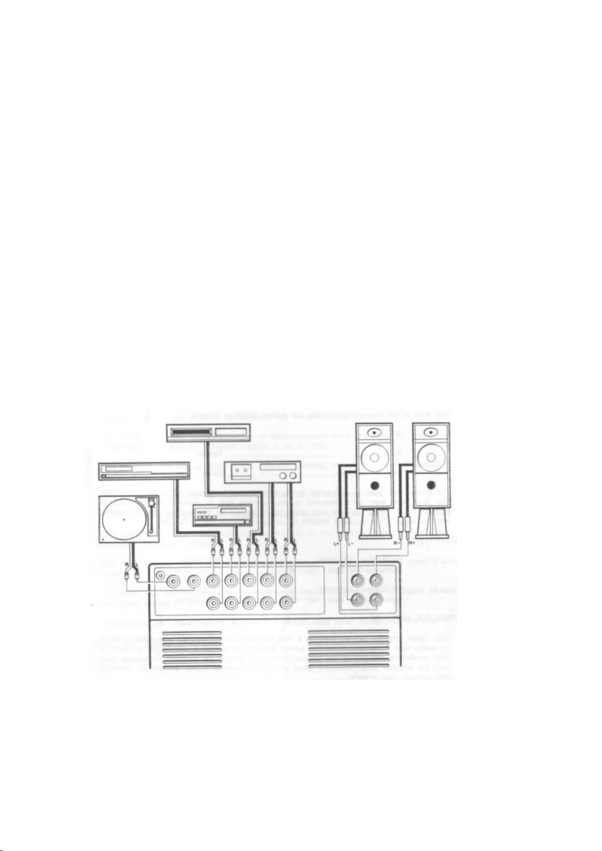
Refer to the wiring diagram of your particular Cyrus amplifier for
connection details.
For best results, the loudspeaker cables used should be of high purity
copper and as short as possible. We strongly recommend our own Mission
or Cyrus loudspeaker cables.
The phono ground terminal (GND), on the rear panel, is provided for
connecting to the appropriate ground wire from your tonearm/turntable.
This will minimise the possibility of hum being induced in the phono
circuitry.
All the RCA phono sockets are colour-coded WHITE for the left and RED
for the right channel.
In the case of the Loudspeaker output terminals, RED is for positive and
BLACK is for negative.
Cyrus One Installation Diagram
Page 5
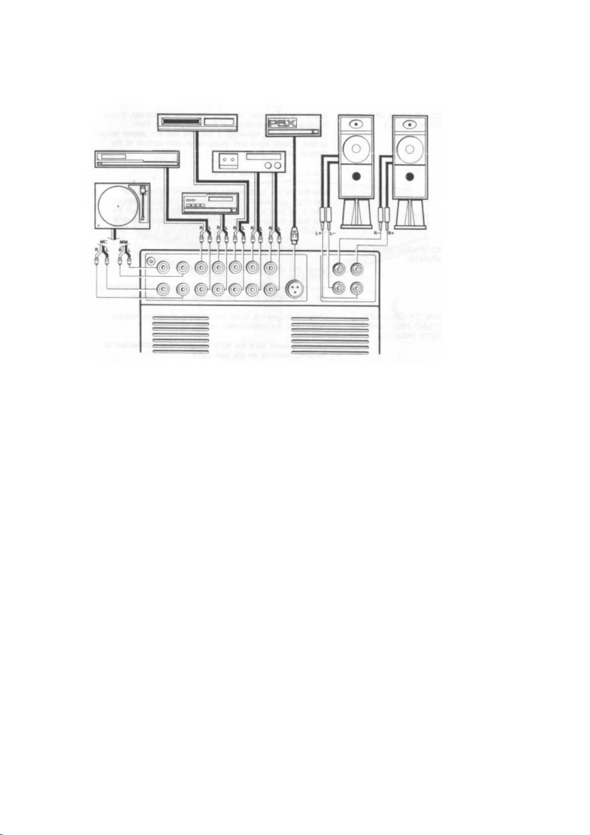
Cyrus Two Installation Diagram
IN CASE OF TROUBLE
CYRUS I AND CYRUS II
THE POWER L.E.D. DOES NOT ILLUMINATE AND THERE IS NO SOUND
Check that the unit is plugged into the mains socket, and the power,
switch is ON.
Check the mains fuse.
AS ABOVE BUT THERE IS SOUND FROM THE SPEAKERS
The LE.D. is faulty.
SOUND FROM ONE SPEAKER ONLY
Check the fault does not occur on other inputs by listening to other
sources. If the fault persists then continue with the following. If not, the
Page 6

relevant source is at fault. Check input and loudspeaker connections of the
channel without sound.
Check loudspeaker fuse if any.
Interchange the loudspeaker connections between Left and Right channels.
Observe whether the fault changes over. If so then the amplifier has a
faulty channel. If the fault stays in the same channel, then the loudspeaker
is at fault.
NO SOUND FROM ANY SPEAKER
Check that the amplifier is On.
Check the sound on the other sources.
If problem persists then the internal fuses of the amplifier may have blown.
Refer the amplifier to your dealer.
HUM OR CRACKLING SOUND FROM ONE OR BOTH SPEAKERS
Check there are no faulty connections along the speaker cables and the
interconnect cables.
Check to make sure the turntable ground is connected to the GND terminal
on the rear panel.
Check that the turntable interconnect is not dressed next to any mains
leads.
MUSIC REPRODUCTION SOUNDS HOLLOW AND STRANGE
Check the speaker cables are connected to the amplifier and speakers
correctly.
If in Phono mode, check the cartridge has been wired correctly.
OPERATING INSTRUCTIONS
Page 7
CYRUS I AMPLIFIER
1. Volume Control: Adjusts the power amplifier output level to the
Loudspeakers from zero to the maximum level.
2. Balance Control: Adjustment of the Balance Control knob swings the
output level to the left or right Loudspeaker by a maximum of 5 dB.
3. "Listen" Selector Switch: Selects the desired source for listening.
Starting from the fully clockwise position, the sources which may be
selected are as follows:
• Phono: Record Player; Moving Coil or Moving Magnet Cartridge.
• Mute: No source selected. May also be used to erase recorded tape.
• CD: Compact Disc Digital Audio Player.
• Tuner: FM/AM Hi- Fi Tuner.
• Video: Hi-Fi Video Recorder, a second Tape Deck (playback only).
• Tape: Tape Recorder used for record and playback (Including R-
DAT).
4. "Record" Selector Switch: Selects the desired source for recording via
the 'Tape-out" socket. Starting from the fully anti-clockwise position, the
sources which may be selected are identical to those on the "Listen"
Selector Switch.
Page 8

Warning: Do not select 'Tape" position on both selector switches
simultaneously. This may cause feedback problems in the tape deck, if it is
in the record mode.
5. Power Switch: Switches the power amplifier section of the unit On (up)
and Off (down). The preamplifier section is powered as soon as the unit is
connected to the mains supply. This feature helps stabilize the operating
temperature of the preamplifier, and optimize the sound quality on switchon.
6. Red LE.D.: When the power switch is up (i.e the amplifier is on)"the red
LED. will light up to indicate fully operational status.
NOTE: It is important that the unit is unplugged from the mains supply if it
is unattended for any length of time. (Vacations, etc.)
REAR PANEL
All inputs plus the tape output are colour coded as follows: RED for the
right channel and WHITE for left channel.
7. Phono Input: Dedicated Input to accept the signal from a Record player.
Page 9

8. MM/MC Switch: This should be set according to the type of cartridge
fitted to the Record player, i.e. MM (Moving Magnet), MC (Moving Coil).
9. CD: Dedicated Compact disc player input.
10. Tuner: Dedicated FM/AM Hi-Fi Tuner input.
11. Video: Input to be used with a Hi-Fi Video recorder or a second tape
deck.
12. Tape: Input suitable for use with a cassette deck, open reel tape deck,
or R-DAT recorder.
13. Tape Out: Carries the signal to be recorded. This should be connected
to the input of the tape recorder.
14. Loudspeaker Outputs: Loudspeakers are connected to the outputs of
the power amplifier at these terminals. These are colour-coded, RED for
positive and BLACK for negative. 4mm banana plugs are used to connect
loudspeaker cables at these points. A set is supplied with the unit.
15. IEC Mains Socket: The mains supply is connected to the unit via this
socket. It has an integral fuse which can only be removed after the mains
lead is disconnected.
TECHNICAL DATA
(REFERENCE TO IHF202)
CYRUS I INTEGRATED AMPLIFIER
Input Sensitivity
(Ref. 1W O/P)
Phono MC 0.04 mV
Phono MM 0.40 mV
Line (CD,Aux,etc.) 65 mV
Input Overload
Page 10

Phono MC 31 dB
Phono MM 31 dB
Line Infinite
Maximum Output Level
Tape out 11 Vrms
Power Amp out 17 Vrms
Input Impedance
Phono MC 47 KOhms
+100 pF
Phono MM 47 KOhms
+100 pF
Line 14 KOhms
Output Impedance
Tape out 150 Ohms
+2.2 MF
Power Amp 0.08 Ohms
Frequency Response
Phono(Ref.New RIAA) 20Hz - 20KHz
+/-0.2 dB
Line 1Hz - 50KHz
-3 dB
Distortion ('T'H D)
Phono MC 0.01%
Phono MM 0.003%
Distortion (SMPTE IMD)
Phono MC 0.01%
Phono MM 0.003%
Signal to Noise Ratio
(A- Weighted 1W output)
Page 11

Phono MC 67 dB
Phono MM 84 dB
Line 86 dB
Minimum Speaker Impedance Load Specification
8 Ohms
Continuous Average Power (Per Channel)
8 Ohms 25 W
4 Ohms 40 W
Damping Factor (20Hz - 20KHz)
100
Dynamic Headroom
1.4 dB
Slew Factor (Input Filter by-passed)
10
Distortion (THD)
1KHz full power
8 Ohms 0.003%
4 Ohms 0.004%
20KHz full power
8 Ohms 0.015%
4 Ohms 0.025%
OPERATING INSTRUCTIONS
CYRUS II AMPLIFIER FRONT PANEL
Page 12

1. Volume Control: Adjusts the power amplifier output level to the
Loudspeakers from zero to the maximum level.
2. Balance Control: Adjustment of the Balance Control knob swings the
output level to the left or right Loudspeaker by a maximum of 5 dB.
3. "Listen" Selector Switch: Selects the desired source for listening.
Starting from the fully clockwise position, the sources which may be
selected are as follows:
• Phono: Record Player; Moving Coil or Moving Magnet Cartridge.
• Mute: No source selected. May also be used to erase recorded tape.
• CD: Compact Disc Digital Audio Player.
• Tuner: FM/AM Hi-Fi Tuner.
• Video: Hi-Fi Video Recorder, a second Tape Deck (playback only).
• Tape: Tape Recorder used for record and playback (Including R-
DAT).
4. "Record" Selector Switch: Selects the desired source for recording via
the "Tape-out" socket. Starting from the fully anti-clockwise position, the
sources which may be selected are identical to those on the "Listen"
Selector Switch.
Warning: Do not select 'Tape" position on both selector switches
simultaneously. This may cause feedback problems in the tape deck, if it is
in the record mode.
Page 13

5. Power Switch: Switches the power amplifier section of the unit On (up)
and Off (down). The preamplifier section is powered as soon as the unit is
connected to the mains supply This feature helps stabilize the operating
temperature of the preamplifier, and optimize the sound quality on switchon.
6. Red LE.D.: When the power switch is up (i.e. the amplifier is on) the red
L.F_.D. will light up to indicate fully operational status.
NOTE: It is important that the unit is unplugged from the mains supply if it
is unattended for any length of time (Vacations, etc.).
REAR PANEL
All inputs plus the tape output are colour ceded as follows: RED for the
right channel and WHITE for left channel,
7. Phono Input: Two separate record player inputs are provided. One set of
inputs are dedicated to Moving Coil cartridges, while the other set is for
Moving Magnet cartridges.
8. MM/MC Switch: Selects between MM (Moving Magnet) and MC (Moving
Coil) pick-up cartridge inputs.
Page 14

9. CD: Dedicated Compact disc player input.
10. Tuner: Dedicated FM/AM Hi-Fi Tuner input.
11. Video: Input to be used with a Hi-Fi Video recorder or a second tape
deck.
12. Tape: Input suitable for use with a cassette deck, open reel tape deck,
or R- DAT recorder.
13. Tape Out: Carries the signal to be recorded. This should be connected
to the input of the tape recorder.
14. PSX Socket: Input for connection to the optional external DC power
supply, Cyrus PSX. The socket is fitted with a blanking cover which your
dealer will remove to enable connection of your PSX.
15. Loudspeaker Outputs: Loudspeakers are connected to the outputs of
the power amplifier at these terminals. These are colour-coded, RED for
positive and BLACK for negative. 4mm banana plugs are used to connect
loudspeaker cables at these points. A set is supplied with the unit.
16. IEC Mains Socket: The mains supply is connected to the unit via this
socket. It has an integral fuse which can only be removed after the mains
lead is disconnected.
TECHNICAL DATA
(REFERENCE TO IHF202)
CYRUS II INTEGRATED AMPLIFIER
Input Sensitivity
(Ref. 1W O/P)
Phono MC 0.02 mV
Phono MM 0.30 mV
Line (CD,Aux,etc.) 50 mV
Page 15

Input Overload
Phono MC 31 dB
Phono MM 31 dB
Line Infinite
Maximum Output Level
Tape out 11 Vrms
Power Amp out 24 Vrms
Input Impedance
Phono MC 100 Ohms + 6.8 nF
Phono MM 47 KOhms + 100 pF
Line 14 KOhms
Output Impedance
Tape out 150 Ohms + 2.2 MF
Power Amp 0.08 Ohms
Frequency Response
Phono(Ref.New RIAA) 20Hz- 20KHz +/-0.2 dB
Line 1Hz - 50KHz - 3 dB
Distortion (THD)
Phono MC 0.005 %
Phono MM 0.003%
Distortion (SMPTE IMD)
Phono MC 0.005 %
Phono MM 0.003%
Signal to Noise Ratio (A - Weighted 1W output)
Phono MC 75 dB
Phono MM 84 dB
Line 86 dB
Minimum Speaker Impedance Load Specification
Page 16

8 Ohms
Continuous Average Power (Per Channel)
8 Ohms 50 W
PSX added
70W
4 Ohms 80 W
PSX added 125W
Damping Factor (20Hz - 20KHz)
100
Dynamic Headroom
1.4 dB
Slew Factor (Input Filter by-passed)
10
Distortion (THD)
1KHz full power
8 Ohms 0.003%
4 Ohms 0.004%
20KHz full power
8 Ohms 0.015%
4 Ohms 0.025%
CYRUS PSX POWER SUPPLY
INTRODUCTION:
The PSX unit can be connected to either a Cyrus II or 767 LFAU providing
a separate DC power supply to the power amplifier section of that unit. The
internal power supply of the Cyrus II or LFAU will now be totally dedicated
to the preamplifier section, enhancing its performance, while the highly
regulated DC supply and the increased current delivery of the PSX will
improve the power amplifier's load handling capability.
Page 17

The PSX, via a separate 4-pin DIN plug, may also be connected to the
Mission PCM II compact disc player. In doing so, the analogue section of
this unit will be provided with a highly regulated and clean DC power
supply, which will in turn enhance its aortic quality. With this arrangement
the internal power supply of the unit will be dedicated to other sections,
such as the Servo, Digital circuitry, and the Display control.
The PSX is housed in a similar case to that of your amplifier. The only
control provided is the power on/off switch, situated on the front panel. On
the rear panel there is an umbilical cord for connection to the Cyrus II or
767 LFAU dedicated PSX input. There is also a 4-pin DIN socket for
connection to the PCM II.
NOTE:
1. To ensure satisfactory system upgrade, it is essential that your dealer or
the Mission service organisation make certain adjustments to your Cyrus II
or 767 LFAU before connecting the PSX power supply.
2. Once the Cyrus II or 767 LFAU has been adjusted for use with the PSX,
the power amplifier will not function without the PSX connected and
switched on.
3. Upgrading the PCM II with the PSX does not require any prior
adjustments.
INSTALLATION
MAINS SUPPLY
A label at the rear of your PSX power supply shows the appropriate mains
supply voltage and fuse rating of the unit. If the mains supply voltage of
your area is different contact your dealer or the Mission service
organisation.
The PSX is connected to the mains supply via an IEC socket and the mains
cable. The IEC socket has an integral mains fuse. When connecting the
mains supply, ensure that the cable is connected to the PSX first.
Page 18

MAINS CABLE
The mains cable supplied with the unit is a three core type, and has an
integral plug attached. Units supplied for the UK market do not have a
mains plug, and therefore, an appropriate plug must be wired according to
the colour-code below and on the label attached to the lead.
All types of mains lead supplied (all countries), have a moulded IEC plug
which matches the IEC socket of your PSX power supply.
FITTING A MAINS PLUG (UK ONLY)
The mains supply cable should be attached to a standard 13 Amp mains
plug that must be fitted with a 5 Amp fuse.
The wires in the mains supply cable are colour coded as follows;
• BROWN = Live
• BLUE = Neutral
• GREEN/YELLOW = Earth
The Brown wire must be connected to the terminal that is marked "L" or
coloured RED. The Blue wire must be connected to the terminal that is
marked "N" or coloured BLACK. The GREEN/YELLOW wire must be
connected to the terminal that is marked with the letter "E" or coloured
GREEN or coloured GREEN AND YELLOW.
MAINS FUSE
• UK/Europe - 220/240V = T3.15A/20mm
• N.America/Far East- 100/120 = T4A/20mm
SITING THE PSX
As with your Cyrus amplifier, the PSX may be free standing or stacked in
an audio rack. The PSX must be sited in a position which allows adequate,
unrestricted airflow around the unit. It should never be placed in a position
close to a source of heat, or exposed to direct sunlight for long periods of
time.
Page 19

The unit has been designed to be placed on the right hand side of your
Cyrus II or 767 LFAU, DO NOT position the PSX immediately above or
below the amplifier.
CONNECTIONS
Before making the connection between the PSX and your Cyrus II or 767
LFAU, first ensure that both units are switched OFF and disconnected from
the mains supply.
OPERATION
When the PSX has been added to your system, you will notice that the
power switch on your Cyrus II or 767 LFAU is ineffective in turning your
system on. The reason for this is, that the PSX is now in control of power
to the power amplifier section of that unit, and the On/Off switch on the
PSX unit should be used to switch the amplifier On or Off.
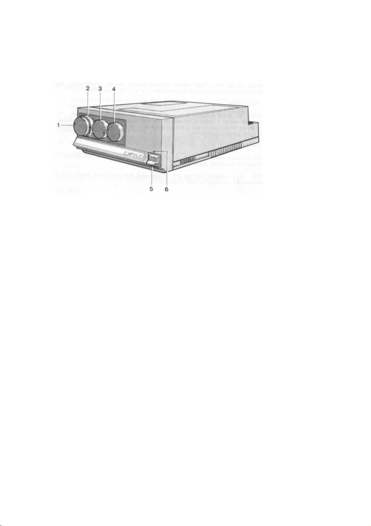
Page 20

1. Power Switch
2. Red LE.D.
3. Lead for connection to Cyrus II or LFAU
4. Socket for connection to Cyrus PCM II
5. I.E.C mains socket
IN CASE OF TROUBLE
CYRUS II OR 767 LFAU/PSX COMBINATION
NOTE: In Cyrus II or 767 LFAU/PSX combination, the power switch of the
Cyrus II or 767 LFAU' is ineffective, as far as the operation of the system is
concerned. The power switch may be turned on (up) to illuminate the L.E.D.
on the unit if so desired.
PSX L.E.D. DOES NOT ILLUMINATE AND THERE IS NO SOUND
Check that the PSX is plugged into the mains socket, and the power switch
is On.
Check the mains fuse of the PSX.
AS ABOVE BUT THERE IS SOUND FROM THE SPEAKERS
The L.E.D. on the PSX is faulty.
SOUND FROM ONE SPEAKER ONLY
Check the fault does not occur on other inputs by listening to other
sources. If the fault persists then continue with the following. If not the
relevant source is at fault.
Check input and loudspeaker connections of the channel without sound.
Check loudspeaker fuse if any.
Page 21

Interchange the loudspeaker connections between Left and Right channels.
Observe whether the fault changes over. If so then the amplifier has a
faulty channel, if the fault stays in the same channel, then the loudspeaker
is at fault.
NO SOUND FROM ANY SPEAKER
Check that the PSX is On.
Check the sound on the other sources.
If problem persists then the internal fuses of the PSX may have blown;
Refer the amplifier and the PSX to your dealer.
NO SOUND FROM ANY SPEAKER WHEN PHONO MODE IS SELECTED
Check that the Cyrus II is plugged in the mains socket, and the power
switch is On.
HUM OR CRACKLING SOUND FROM ONE OR BOTH SPEAKERS
Check there are no faulty connections along the speaker cables and the
interconnect cables.
Check to make sure the turntable ground is connected to the GND terminal
on the rear panel.
Check that the turntable interconnect is not dressed next to any mains
leads.
MUSIC REPRODUCTION SOUNDS HOLLOW AND STRANGE
Check the speaker cables are connected to the amplifier and speakers
correctly.
If in Phono mode, check the cartridge has been wired correctly.
 Loading...