

Page 1
151153EN-G
DMC 3000 User’s Guide
Health Physics
Division
Radiation Safety. Perfected.
151153EN-G
Page 2

-2-
151153EN-G
DMC 3000 User's Guide
Revision Log
Revision Date Veried by Approved by
Origin and description
of revision
Modied Pages
A-D
From 2012-06
to 2012-10
J. PEREZ P. MARTIN N.A /
E 2015-03 J. PEREZ P. MARTIN DEVN 23331
Introduction of Beta
and Neutron Modules
All pages
F 2015-04 J. PEREZ C. DONNAY DEVS 23437
Drawings edited
14-16, 19
G 2015-11 R. DANQUIGNY P. MARTIN DEVS 23988
New features
Introduction of PRD module
7-11; 21-22;
42-43; 45
Page 3

-3-
151153EN-G
DMC 3000 User's Guide
Table of Contents
1- Presentation ...........................................................4
2- General ...................................................................5
2.1 Use and Functionality ............................................. 5
2.2 Compatibility with Mirion Technologies Products .. 6
2.3 Functionalities ......................................................... 8
2.4 Historical Data Function ...................................... 12
2.5 Handling Recommendations ................................ 13
3- Operation .............................................................14
3.1 Fast Entry Mode ................................................... 14
3.2 Operating Modes .................................................. 14
4- States Modes .......................................................15
4.1 Run / Pause Flow Diagram ................................... 16
4.2 Browsing Diagram in Pause.................................. 17
4.3 Browsing Diagram in Run ..................................... 18
4.4 Set Point Modications in autonomous mode ..... 19
4.5 Data & Parameters List ......................................... 20
5- Alarms ..................................................................21
5.1 Dose and Rate Alarms or Warnings ...................... 22
5.2 Saturation ............................................................. 24
5.3 Time Alarm ............................................................ 25
5.4 Low Battery .......................................................... 26
5.5 Power Loss (after low battery) .............................. 27
5.6 Faults .................................................................... 27
6- Battery Replacement ...........................................32
7- Clip Replacement .................................................33
7.1 Standard or Belt Clip ............................................ 33
7.2 Front Facing Clip .................................................. 33
8- Manual Calibration & Maintenance ......................34
8.1 Manual Calibration ................................................ 34
8.2 Maintenance ......................................................... 35
9- Technical Characteristics .....................................36
9.1 Physical Characteristics ....................................... 36
9.2 Electrical Characteristics ...................................... 37
9.3 Mechanical Characteristics .................................. 37
9.4 Environmental Characteristics .............................. 38
9.5 Factory Calibration and verication ..................... 38
9.6 Functional Characteristics .................................... 39
9.7 Environment .......................................................... 40
9.8 Reference point of calibration ............................... 41
10- Add-on Modules ................................................42
10.1 Dedicated documentation .................................. 42
10.2 Module Attachment ............................................ 42
10.3 DMCUser parameters ......................................... 43
10.4 Module Detachment ........................................... 44
11- Accessories References.....................................45
12- CE Certicate .....................................................46
13- Verication Certicate ........................................47
Page 4
-4-
151153EN-G
DMC 3000 User's Guide
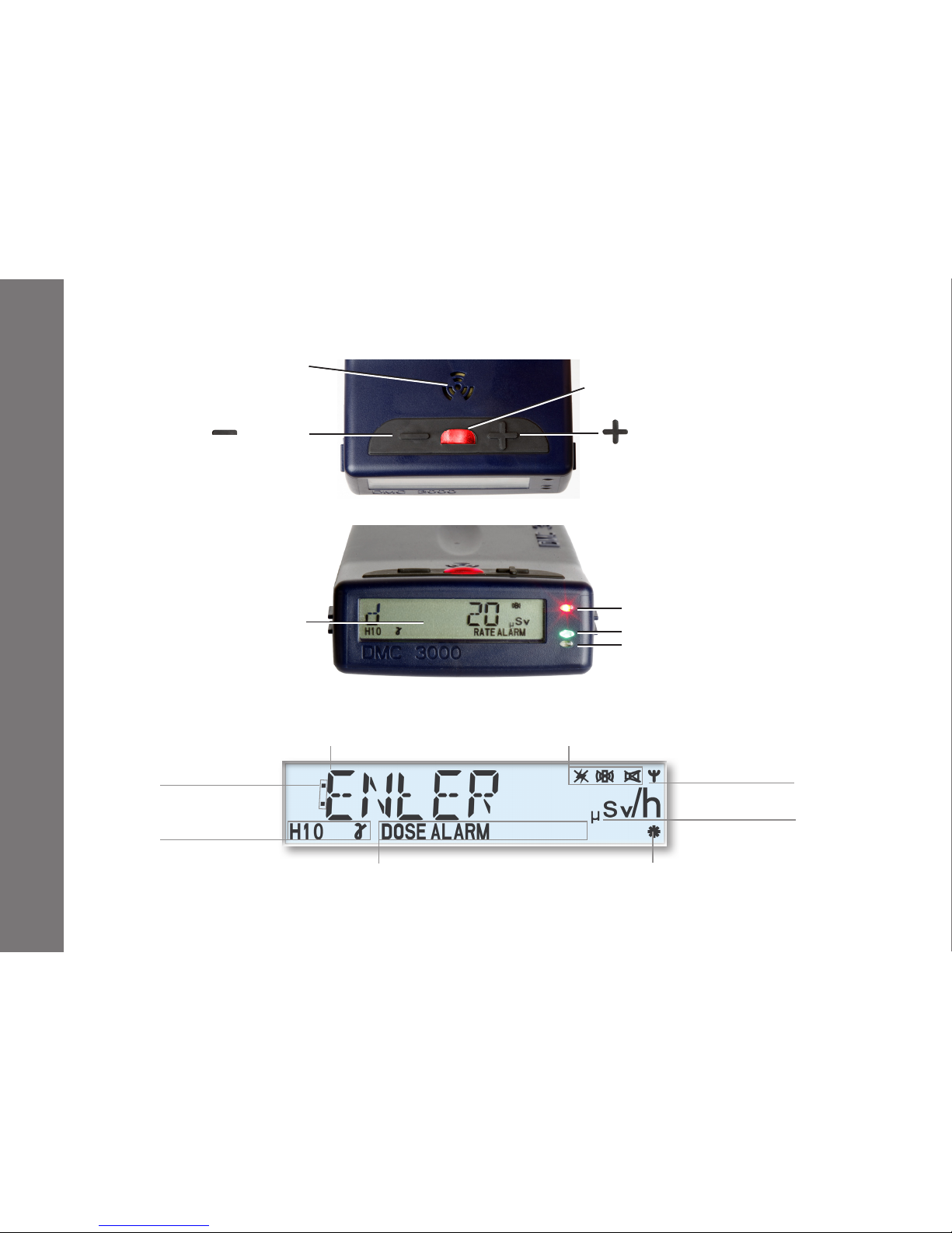
Button for
data display
Button for
parameters display
Speaker
Front red ashing LED
for alarm
Connected module
indicator
Measurement
unit
G2 "DMC 2000" compatible protocolAlarm type
Measurement
type
Measurement or
parameter display area
Disable red ash, vibrator and speaker indicators
Top red LED for alarm
Green LED for gamma counting
Blue LED for Hp(0,07), neutron and PRD counting
Large backlit display
with 8 digits
Functional indicator
"blinking"
1- Presentation
Page 5

-5-
151153EN-G
DMC 3000 User's Guide
2- General
2.1 Use and Functionality
The DMC 3000 is the compact, rugged and reliable dosimeter designed to detect a wide range of X-ray and
gamma radiations.
The large-format, backlit, high-contrast 8-digit LCD display provides clear dose and dose rate readings for
deep dose equivalent Hp(10).
Additionally, it provides multiple methods to alert the wearer of alarm conditions, including:
A high decibel speaker
1 ashing LED on the front face
A backlit LCD display
3 bright LEDs on the top
A vibrator.
(See Chapter 5 for a complete description of these alarms.)
The indication of dose increment is visible with the green LED or blue LED even when
an alarm is given by the two red LEDs.
Two buttons are used for easy access to all the DMC 3000's functionality.
(See Chapter 4 for more information on button use.)
Page 6
-6-
151153EN-G
DMC 3000 User's Guide
2.2 Compatibility with Mirion Technologies Products
The DMC 3000 features two protocols, G3 and G2, that use the same communication medium, with an omnidirectional, low-frequency (125 kHz) transceiver.
The enhanced "G3" communication protocol to support additional features and attached measurement
modules. It also includes a compatibility mode for previous Mirion Technologies products including Access
Control, Turnstiles and Telemetry devices.
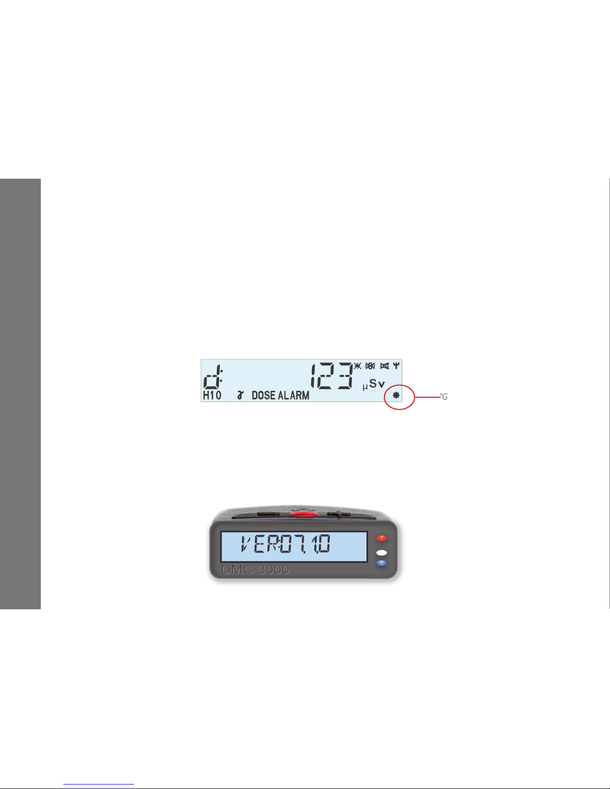
The compatible DMC 2000 communication protocol "G2" is indicated on the DMC 3000 by an asterisk in
the display's bottom right corner. This guarantees compatibility with the existing Mirion readers (LDM 220,
LDM 2000 and LDM 3000) and software (DosiServ, DosiCare, DosiFFR and Sentinel).
Note: G2 protocol is available only on V5 rmware version.
The enhanced communication protocol "G3" requires new readers such as the LDM 320D, LDM 320W,
LDM3200 or LDM 2000 with upgraded rmware.
Attached measurement modules (neutron Hp(10), beta Hp(0,07), PRD...) can be added when the DMC 3000 is
in “G3” protocol and with rmware version V.7. See §10 for Add-on modules information.
Telemetry module can be added to the DMC 3000 whatever the protocol “G2” or G3”.
General
"G2" DMC 2000 compatible protocol
Page 7
-7-
151153EN-G
DMC 3000 User's Guide
General
V7 firmware version:
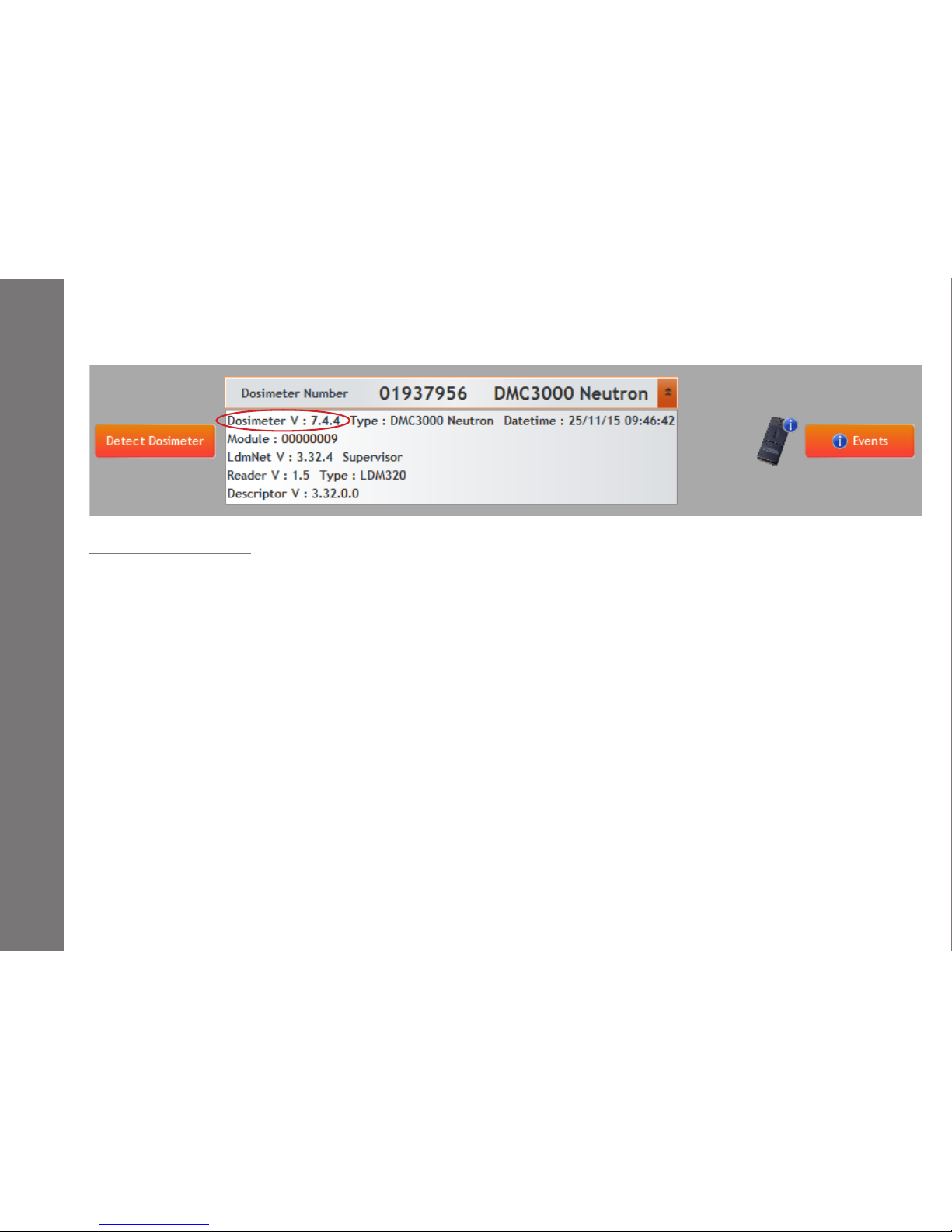
V 7.2.1: G3-only protocol; compatible with neutron Hp(10) and beta Hp(0,07) modules.
V 7.4.4: Added dose display resolution of 0.1 µSv, added prealarm latched until acknowledgement.
Future release: Added PRD module support.
The DMC 3000 must be calibrated for Hp(0,07) gamma at the factory prior to initial use with the Hp(0,07) Module.
Check the verication certicate to see the calibration in Hp(0,07) of your DMC 3000.
Please contact Mirion Technologies for compatibility diagnostic and information.
If the rmware version is not viewable by pressing “+” key, use DMCUser software.
Page 8
-8-
151153EN-G
DMC 3000 User's Guide
General
2.3 Functionalities
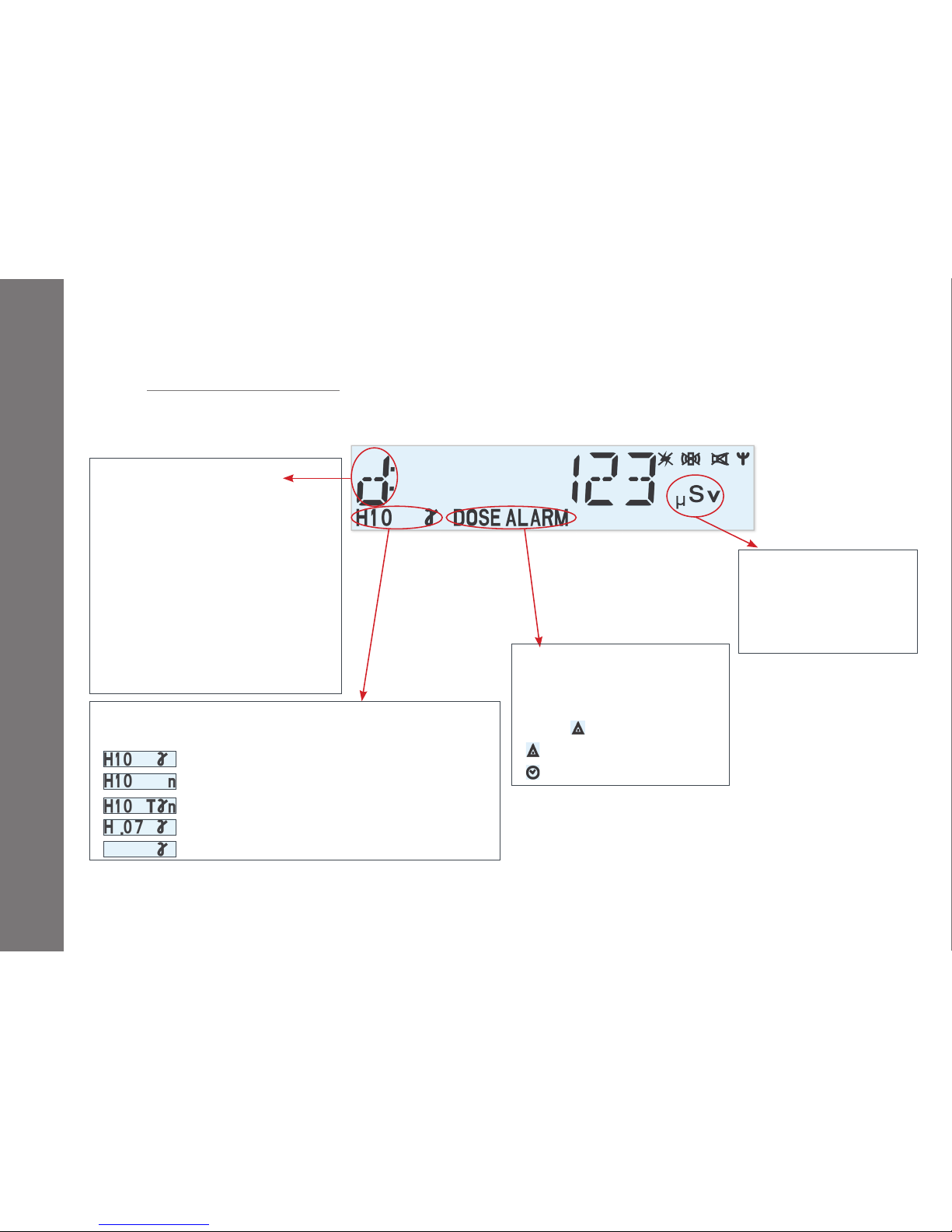
2.3.1 Dose, Rate Notification
The high contrast and backlit LCD display provides clear indication of dose, rate and other information with 8
digits and symbols. Whatever the unit there is no scale change for the whole range.
The data information displayed on the DMC 3000 is selectable using DMCUser software.
When in pause mode (no measurement) the DMC 3000 can display PAUSE, SLEEP, ASSIGN, the wearer name,
the calibration due date or a user message
Notication:
d: for dose
R: for rate
h: Run time (hh:mm:ss)
t: Remaining Time before alarm
V: Life dose or life time
M: maintenance dose or time
xxx dEF Default, "xxx" identies
the type of default (see §5.6.3
Troubleshooting guide)
Origin of dose/Rate displayed
(measurements or alarm thresholds).
: X+Gamma Hp(10)
: Neutron Hp(10)
: total dose ((X+Gamma) + neutron Hp(10))
: beta and X+Gamma Hp (0.07)
: Gamma rate in counts per second (PRD)
Blinking Alarm Indicator:
DOSE ALARM: Dose Alarm
ALARM RATE: Rate Alarm
DOSE : Dose pre-alarm
RATE: Rate pre-alarm
: Time Alarm
Dose, Rate unit can be:
µSv (/h),
mSv (/h),
mrem (/h)
Page 9
-9-
151153EN-G
DMC 3000 User's Guide
2.3.2 Dose Increment Notication
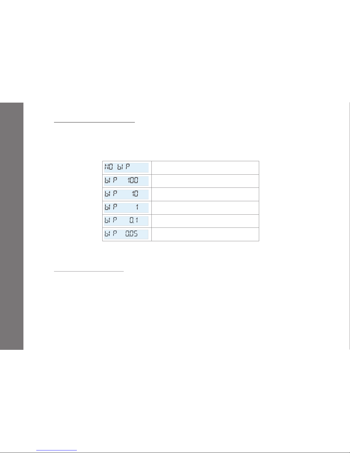
The green LED gives the rate of primary X+Gamma Hp(10) dose increments (one ash each 1 µSv).
The blue LED is dedicated to secondary Hp(0,07) or neutron dose increments with DMC 3000 attachments.
An audible beep can also be generated, following the primary X+Gamma dose increment (see below conguration) or secondary Neutron or Hp(0,07) dose increment.
General
no audible signal for dose increments
1 beep every 100 µSv (10 mrem)
1 beep every 10 µSv (1 mrem)
1 beep every 1 µSv (0.1 mrem)
1 beep every 0.1 µSv (0.01mrem)
1 beep every 0.05 µSv (0.005mrem)
The conguration of the blue LED on secondary dose increments and the audible beep if from the secondary
dose is selectable separately (see user's manuals of module).
2.3.3 Display Dose Resolution
On rmware V7.4.4 or greater, the dose resolution on the display is selectable (10, 1 or 0.1 µSv) (
See note 1) with
DMCUser:
With resolution 10 or 1µSv, the dose is displayed over the entire range without any unit change.
With resolution 0.1 µSv, the dose is displayed with 0.1 µSv resolution from 0.0 µSv up to 999 999.9 µSv then
the dose is displayed with 1µSv resolution up to 9 999 999 µSv.
Note 1: or equivalent depending on unit selected.
Note 2: the dose change is linked to the number of counts and the algorithm parameters of the dosimeter (eciency, integrated time 10s, 60s).
Page 10

-10-
151153EN-G
DMC 3000 User's Guide
2.3.4 Remaining Time before Alarm
Displayed as a timer counting down, the time to alarm corresponds to either the time alarm or the time to reach
the dose alarm point, whichever is shortest.
The time to reach the dose alarm point is calculated as follows:
time duration before dose alarm = (dose alarm threshold - cumulative dose) / current dose rate
2.3.5
Rate Alarm Latched
The DMC 3000 allows users to latch the rate alarm.
Three options are oered:
regular speaker sound follows the rate alarm
rate alarm latched 10 seconds. Speaker sound and visual alarms are tended to 10 seconds after the rate
alarm stops (
See note)
rate alarm latched until pause
General
Note:
This new feature is available and congurable only in G3 protocol.
2.3.6 Rate Pre-Alarm Latched until acknowledgement
On version V7.4.4 (or greater), the rate pre-alarm (Alert) can be latched until acknowledgement for a recognition by the worker.
Page 11
-11-
151153EN-G
DMC 3000 User's Guide
2.3.7 Add-on Module
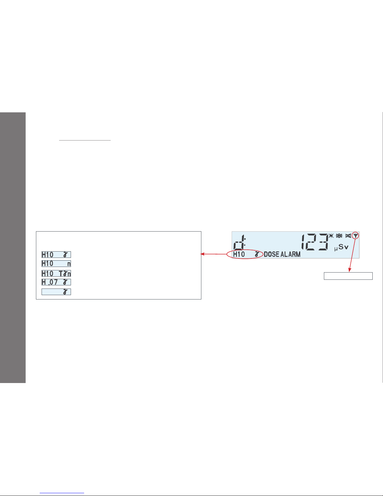
An additional module, such as a telemetry device, Hp(0,07) beta, Hp(10) Neutron or PRD module can be attached at the bottom of the DMC 3000 simply by removing the battery cover.
All these add-on modules have their own parameters saved on non-volatile memory and modify the display
conguration of the DMC 3000 when attached to it.
A module must be connected/disconnected to the DMC 3000, only when in PAUSE.
The Ψ icon appears at the top right corner of the display when a module is detected and measurement type
icon (on the bottom left corner of the display) gives the origin of Dose/Rate displayed (measurement or alarm
threshold).
General
Origin of Dose/Rate displayed
(measurements or alarm thresholds).
: X+Gamma Hp(10)
: Neutron Hp(10)
: total dose ((X+Gamma) + neutron Hp(10))
: beta and X+Gamma Hp(0.07)
: Gamma rate in counts per second (PRD)
Module connected
Page 12

-12-
151153EN-G
DMC 3000 User's Guide
2.4 Historical Data Function
DMC 3000 series dosimeters in G3 protocol have a historical data function which allows the following features:
Recording and dating of changes equal or greater than 1 µSv (0.1 mrem) in the cumulative doses (primary
and/or secondary) with the current Rate by intervals of 10 seconds, 1 minute, 10 minutes, 1 hour or 24 hours
depending on the dosimeter’s conguration.
Recording and dating of maximum rate between two dose records
Recording every second during 10s on rate alarm transition
Decreasing of the interval or record (10s instead of 1mn for exemple) when in Rate alarm for better accuracy
Recording and dating of signicant events such as:
alarms and warnings
acknowledgment of warnings
assignment of identier, task and RWP codes
change in operating mode (Pause and Run)
dosimeter fault
parameter changes
In order to date accurately all the data, the DMC 3000 is equipped with a Real Time Clock to keep the clock
time. In satellite mode, this RTC could be set during conguration with a reader during entry.
In G3 protocol, all the events and dose increments are dated in date format (DD/MM/YYYY and HH:MM:SS) and
the time size of recording is doubled (DMC 3000 alone or the same DMC 3000 with module) compared to G2
(DMC 2000 compatible) protocol (see note).
General
Note:
Calculated with an increment of dose every 10 histogram steps.
Page 13
-13-
151153EN-G
DMC 3000 User's Guide
2.5 Handling Recommendations
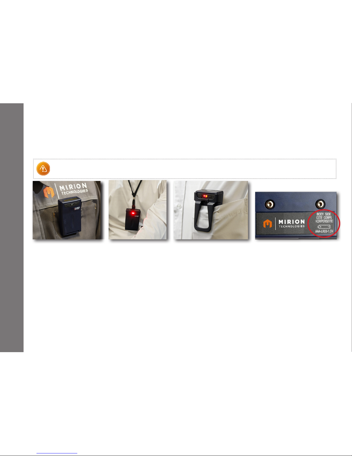
As the DMC 3000 oers the ability to clip it either outside the pocket, (standard or belt clip) or inside
(front side clip), users should remember to wear the dosimeter with its back side facing the body.
(See label on the battery cover.)
As the energy range of the DMC 3000 starts at 15 keV, the detection area of the dosimeter should not be
covered with any heavy material, like metal, in order to ensure the most accurate dose measurement.
Belt clip is strongly discouraged when a module is attached to the dosimeter, because module reduce the gap
of the clip.
The use of a front facing clip is forbidden with an Hp(0,07) beta module, because no material must be in front
of the beta detector.
The DMC 3000 will warn you when the battery needs to be replaced. A completely discharged battery can cause
leakage that may damage your DMC 3000. Thus, dead batteries should be removed or replaced promptly.
Only approved batteries or high quality Alkaline batteries should be used with your DMC 3000 (see Chapter 6).
There are no serviceable parts inside your DMC 3000. Thus, tampering with the case will compromise the
waterproong and void the warranty.
General
Warning:
For the DMC 3000 vibrator alarm to be eective, the unit must be in contact with the body for the user to feel it.
Page 14
-14-
151153EN-G
DMC 3000 User's Guide
3.1 Fast Entry Mode
The DMC 3000 can be started up using a simplied and quick procedure.
Fast entry must be enabled using DMCUser software.
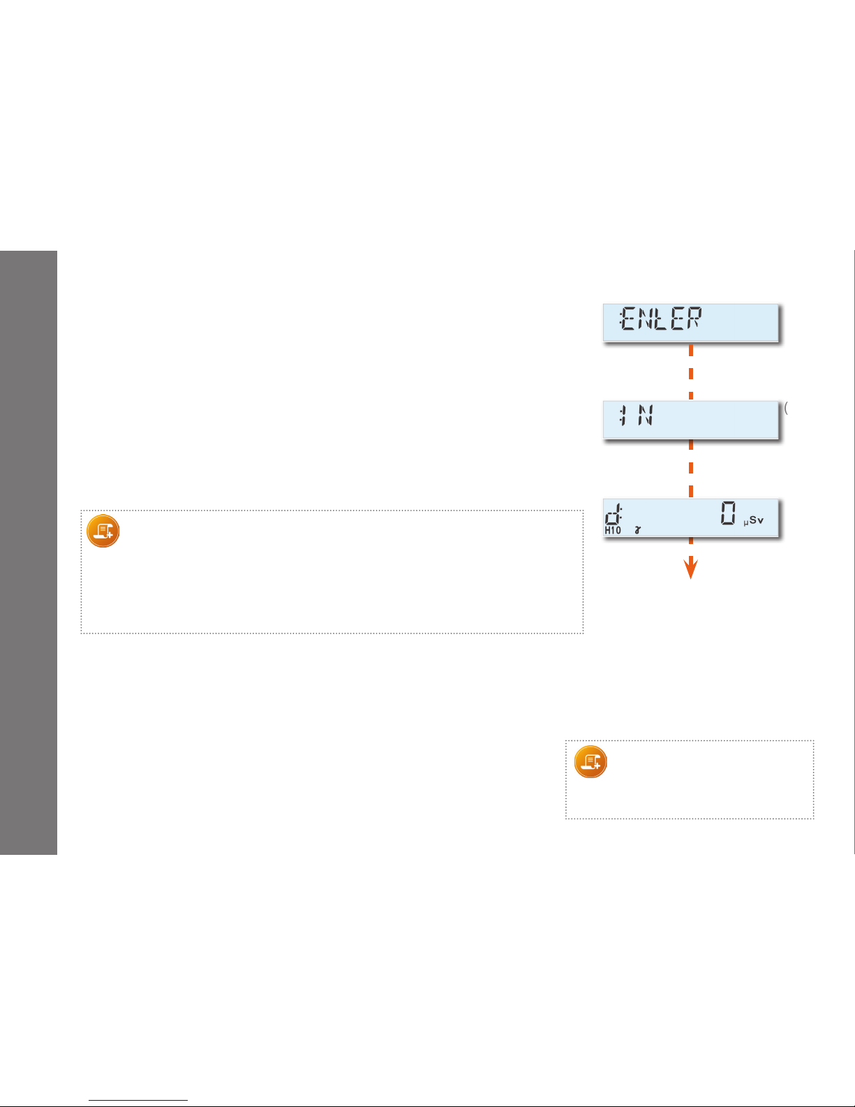
When fast entry is enabled, the message "ENtER" (1) is
displayed. Simply pressing one of the 2 control buttons immediately
switches the DMC 3000 dosimeter into Run mode.
The message "IN" (2) is briey displayed (*).
The dosimeter switches to measurement mode (3).
The display starts to indicate the dose measurement.
Note:
There are two congurations of fast entry (Fast entry and permanent fast entry)
- In fast entry, as soon as the dosimeter switches back to Pause mode, the fast entry
mode is disabled. To return to fast entry mode set parameters again.
- If the permanent fast entry mode is set, the DMC 3000 will revert to fast entry mode when back
in Pause.
(*) Depending on the versions, the message "IN" may not be displayed.
(1)
(2)
(3)
Note:
DOSIMASS-DM does not have the
ability to modify the DMC 3000's
parameters.
3.2 Operating Modes
DMC 3000 dosimeter can be used in the following modes:
- Autonomous mode:
Dosimeter's two buttons can be used to set alarm set points and switch
back and forth between Pause and Run.
- Satellite mode:
DMCUser software must be used to congure the DMC 3000.
Readers must be used to turn ON (Run) and OFF (Pause) the DMC 3000.
3- Operation
Page 15
-15-
151153EN-G
DMC 3000 User's Guide
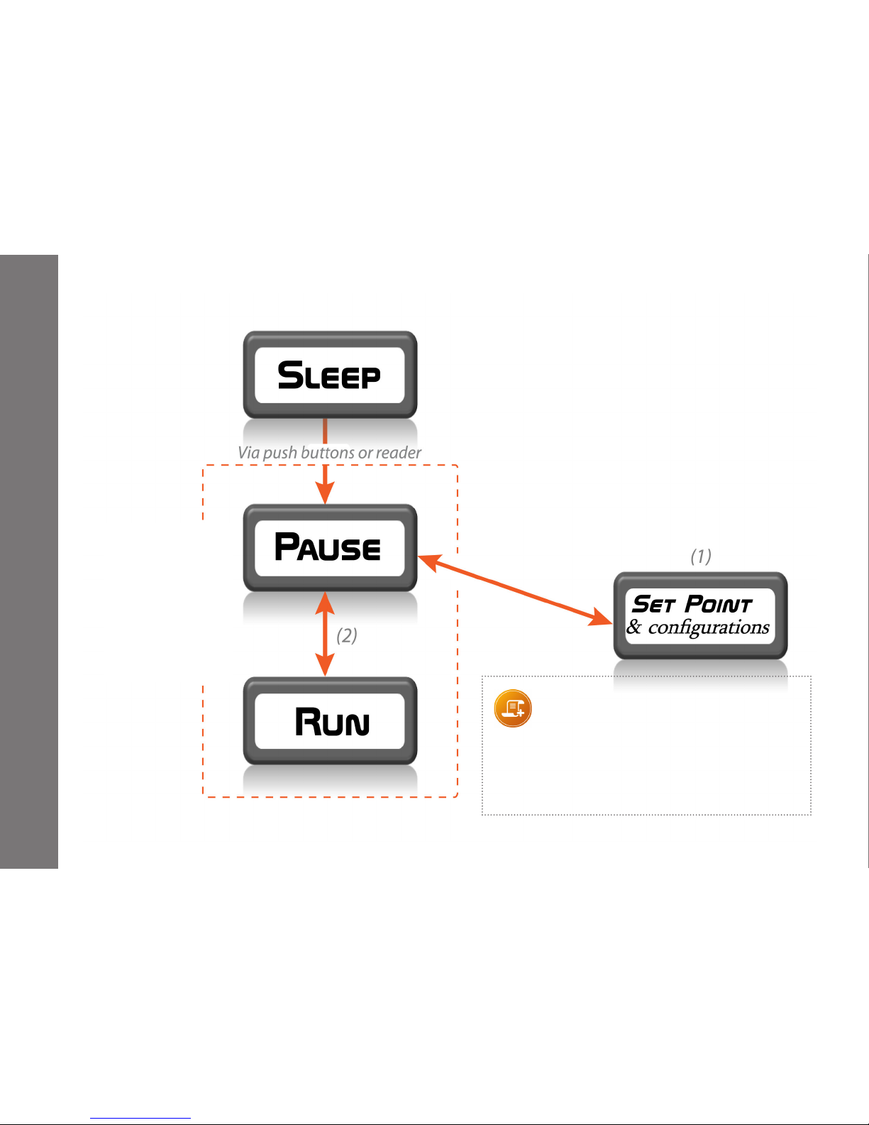
The sleep mode state is a low-power consumption
state where the functional indicator ":" does not
blink.
When either button is pressed, or during communication with a reader, the DMC automatically goes
into Pause with a backlit display and all display
segments activate for 2 seconds.
Note:
- The rst press on any push button only turns
on the backlight for 3 seconds.
(1) The conguration of the set point is available in
autonomous mode only.
(2) Done manually in autonomous mode or
with the use of a reader in satellite mode.
4- States Modes
How to congure
in autonomous?
See § 4.4
How to switch
between
Pause and Run
modes in
autonomous?
§ 4.1
Page 16
-16-
151153EN-G
DMC 3000 User's Guide
States Modes
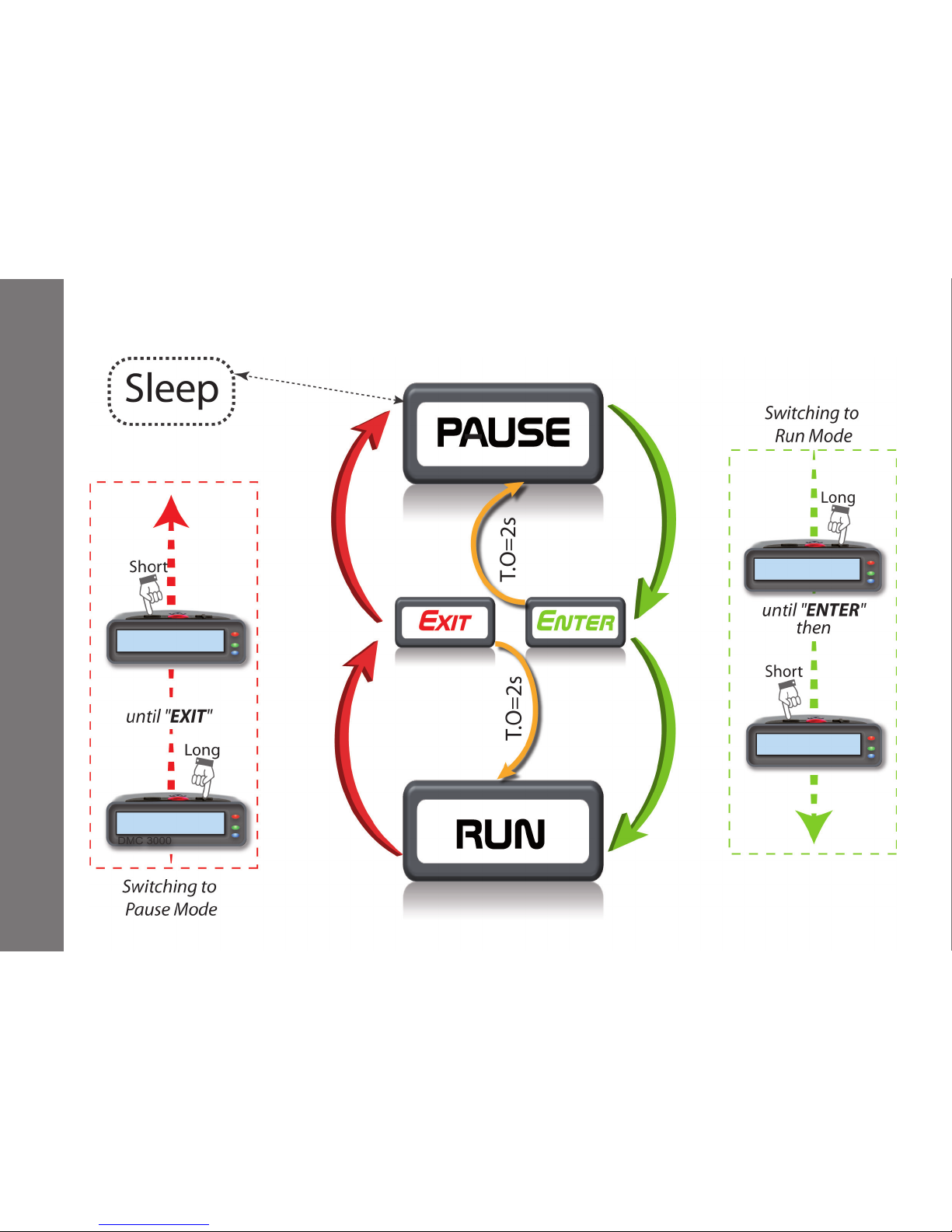
Long press >2s
T.O = Time Out
4.1 Run / Pause Flow Diagram
Page 17
-17-
151153EN-G
DMC 3000 User's Guide
States Modes
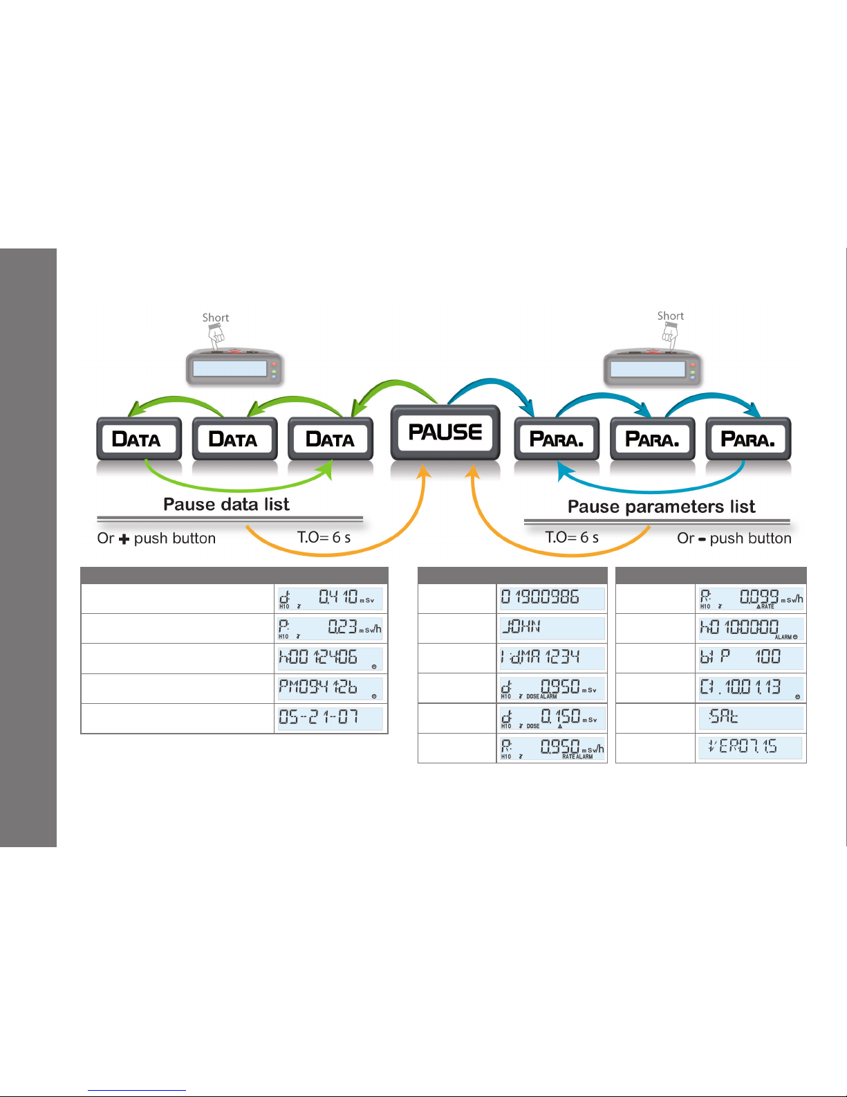
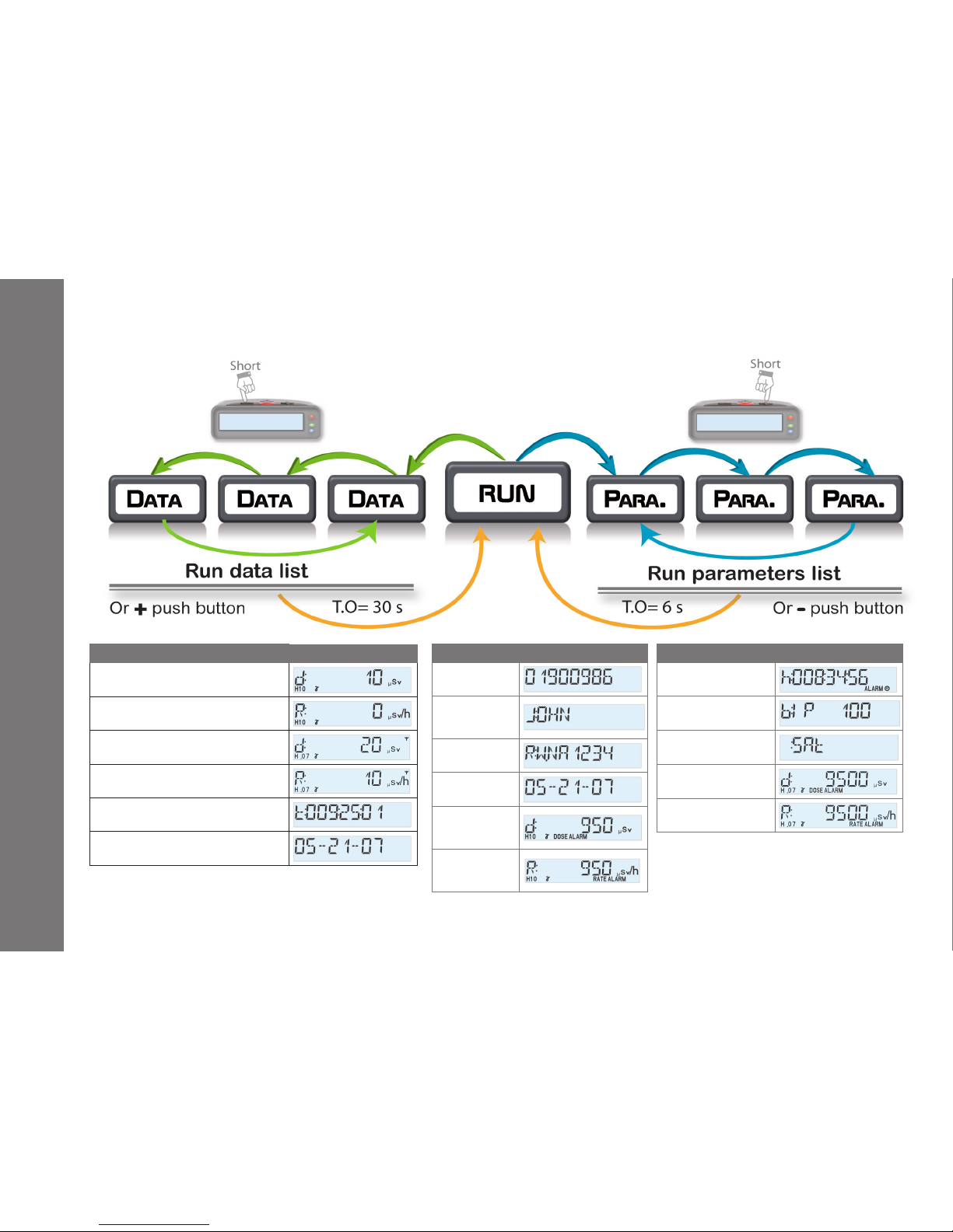
Exemple of Data available Display
Last recorded X + Gamma Hp(10) dose
Last maximum X + Gamma Hp(10)
peak rate
Last duration in Run
Current Time
(AM/PM or 24H format)
Current Date
(MM--DD--YY or DD/MM/YY format)
Parameters Display
Dosimeter
number
Wearer’s name
Wearer ID
Dose alarm set
point
Dose warning
set point
Rate alarm set
point
Parameters Display
Rate warning set
point
Run time
warning set point
Chirp mode
Date of next
calibration
Dosimeter mode
Software
version
Data list in Pause and Run are congurable
with
dmc
User (choice and order) and depend
on module connected and conguration.
See § 4.5 for complete list.
Parameter list in Pause and Run are congurable with
dmc
User (choice and order) and depend on module
connected and conguration. See § 4.5 for complete list.
4.2 Browsing Diagram in Pause
Page 18
-18-
151153EN-G
DMC 3000 User's Guide
States Modes
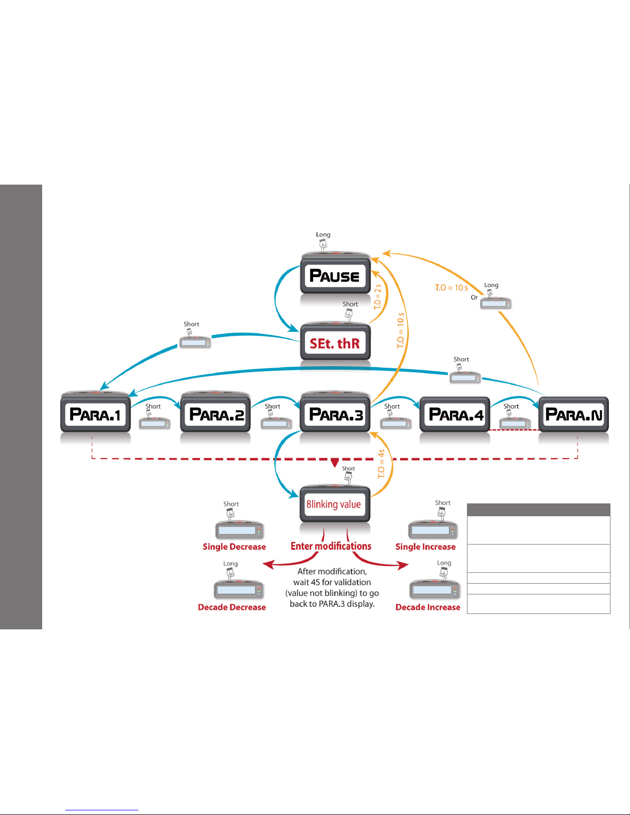
Exemple of Data available Display
Current X + Gamma Hp(10) dose
Current X + Gamma Hp(10) rate
Current Hp(0,07) shallow dose
Current Hp(0,07) shallow rate
Remaining time before alarm in
Run
Date
Parameters Display
Dosimeter
number
Wearer’s name
RWP
Date
X + Gamma
Hp(10) Dose
alarm set point
X + Gamma
Hp(10) Rate
alarm set point
Parameters Display
Run-time warning set
point
Chirp mode
Operating mode
Hp(0,07) shallow dose
alarm set point
Hp(0,07) shallow rate
alarm set point
4.3 Browsing Diagram in Run
Page 19
-19-
151153EN-G
DMC 3000 User's Guide
States Modes
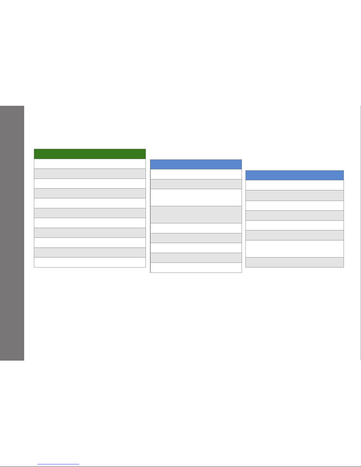
4.4 Set Point Modifications in autonomous mode
List of available parameters
Dose / Dose Rate Alarm thresholds
(primary, secondary and total measurements)
Dose / Dose Rate Pre-alarm thresholds
(primary, secondary and total measurements)
Reset or Total Dose
Time Alarm thresholds
Note: items availability is based on dosimeters
conguration
Page 20
-20-
151153EN-G
DMC 3000 User's Guide
States Modes
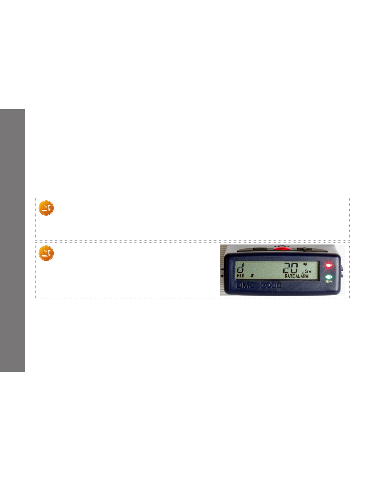
Data
Hour (1)
Date (1)
Full life dose (1)
Full life duration (1)
Total maintenance dose (1)
Total maintenance duration (1)
Dose (1)
Current rate (1)
Maximum rate (1)
Duration of integration in Run (1)
Remaining time before alarm in Run (1)
Parameters
User name (1)
Dosimeter number (1)
Type of autonomous dose
(cumulated or reset) (1) (2)
Date of next internal
calibration (1)
Dose alarm setpoint (1) (2)
Rate alarm setpoint (1) (2)
Duration setpoint (1) (2)
Dose warning setpoint (1) (2)
Rate warning setpoint (1) (2)
Parameters
Beeps at dose change (1)
Autonomous or satellite ag (1)
Software version (1)
FLASH memory checksum (1)
Worker identier (1)
Worker order task code (OT) (1)
Thermoluminescent lm number
(TLD) (1)
Radiation Work Permit (RWP) (1)
The following data and parameter options are available in Pause and Run mode.
They can be selected and ranked by preference, using
dmc
User software.
(1)This item's availability is based on the dosimeter's conguration.
For example, if the rate display is not chosen the current rate and maximum rate will not be displayed.
In G2 protocol, some data or parameters are not available.
(2)These items are settable in autonomous mode.
(3) See
dmc
User software for the complete list of data and parameters available.
4.5 Data & Parameters List
Page 21
-21-
151153EN-G
DMC 3000 User's Guide
5- Alarms
The DMC 3000 dosimeter provides multiple methods to alert the wearer of alarming conditions:
A loud audible alarm is emitted by the dosimeter speaker
A message or symbol “Alarm Type” appears on the high-contrast LCD display with backlight ON during
3seconds
Very bright red ashes from the front red ashing LED
Red ashes from the top red LED
Vibrations
Note:
- In case of simultaneous alarms, corresponding messages and symbols are displayed based on priority level.
- Speaker, vibrator, blacklight, front red ashing LED and top red LED can be disabled when conguring the DMC 3000.
This function can be modied using the DMCUser maintenance software in G3 protocol only.
Look at the pictogram on the top right corner of the display to know which alarm is disabled.
Note:
Alarm type displayed is independent of the measurement
displayed (for exemple, alarm type can be “RATE ALARM”
when Dose value is displayed).
Page 22
-22-
151153EN-G
DMC 3000 User's Guide
Alarms
5.1 Dose and Rate Alarms or Warnings
On DMC 3000 rmware V.7, the DMC 3000 has 2 congurable dose alarms from 1 µSv to 10Sv and 2 con-
gurable rate alarms from 10 µSv/h (*) to 10 Sv/h for Hp(10) (X + Gamma) deep dose, X + Hp(0,07) Gamma +
Beta shallow dose or Hp(10) Neutron dose and 2 congurable total dose alarms Gamma + Neutron.
(*) Please contact Mirion Technologies for a rate set point between 1 µSv/h and 10 µSv/h.
Dose and rate warnings are acknowledgeable by pressing either push button for longer than 3 seconds.
The rate alarm and warning occur when the rate exceeds the set point. The rate alarm and warning disap-
pear when the rate decreases to 80% of the set point if latched feature is enabled (see §2.3.5 and §2.3.6).
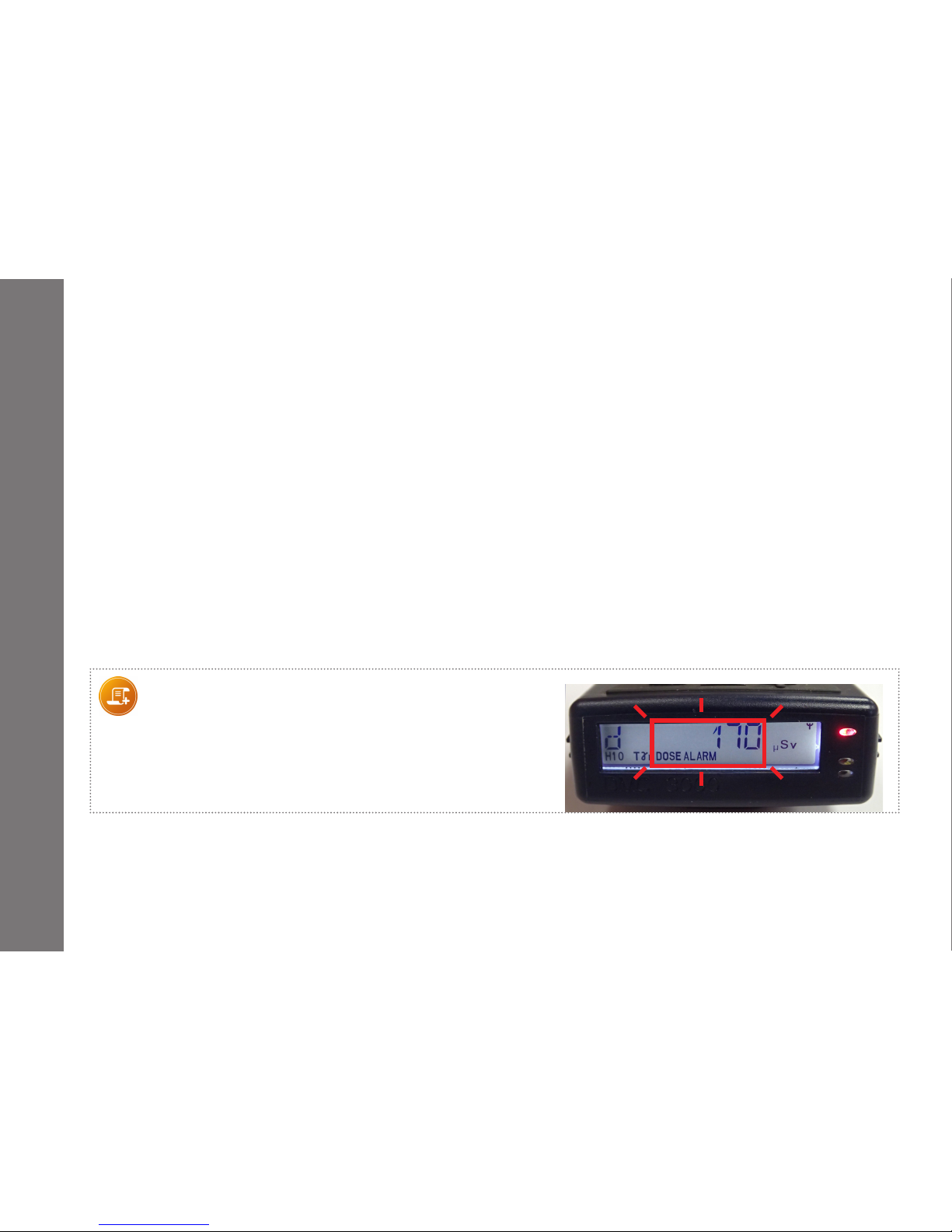
On DMC 3000 rmware V.7, the displayed value of dose or rate blinks simultaneously with the indicator
when it has generated the alarm or warning, see example below.
Note:
When displaying a measure (here, Total dose), the value and DOSE
ALARM are blinking, notifying an alarm on the total
Gamma+Neutron dose.
Page 23
-23-
151153EN-G
DMC 3000 User's Guide
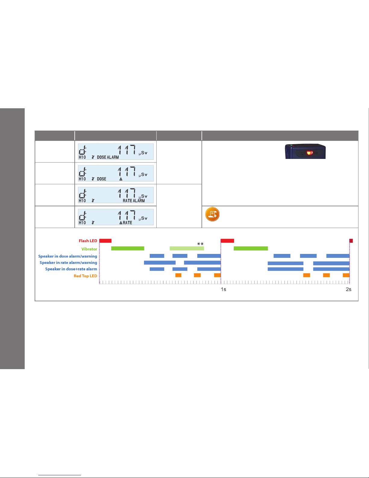
Alarm Type Display Speaker Flash LED, Vibrator and Top Red LED
Dose Alarm
3 beeps
every second
FLASH LED
1 ash every second
VIBRATOR
1 vibration (**) every second
** An extra vibration is added if the speaker is disabled.
TOP LED
3 red ashes every second
Dose Warning
(See note)
Rate Alarm
2 long beeps
every second
Rate Warning
(See note)
Note :
Acknowledge by pressing + or - button longer than 3s.
Alarms
Page 24
-24-
151153EN-G
DMC 3000 User's Guide
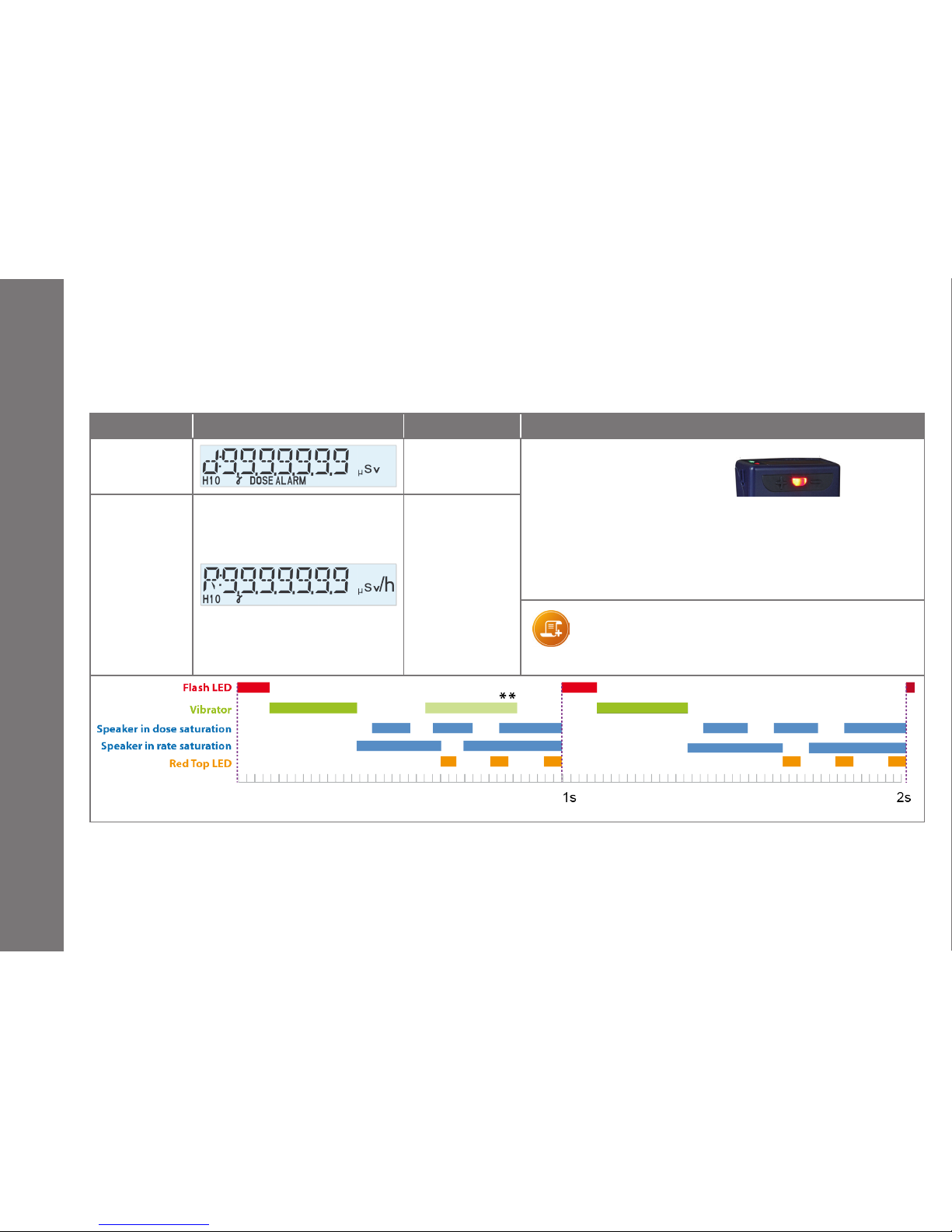
Alarm Type Display Speaker Flash LED, Vibrator and Top Red LED
Dose Saturation
3 beeps
every second
FLASH LED
1 ash every second
VIBRATOR
1 vibration (**) every second
** An extra vibration is added if the speaker is disabled.
TOP LED
3 red ashes every second
Rate Saturation
(see note)
2 long beeps
every second
Note:
during the rate saturation and after the rate saturation,
the message “RAtE SAt “is displayed in alternance with the
current display.
Alarms
5.2 Saturation
When the dose or dose rate reach the maximum value the saturation is displayed as follows:
Page 25
-25-
151153EN-G
DMC 3000 User's Guide
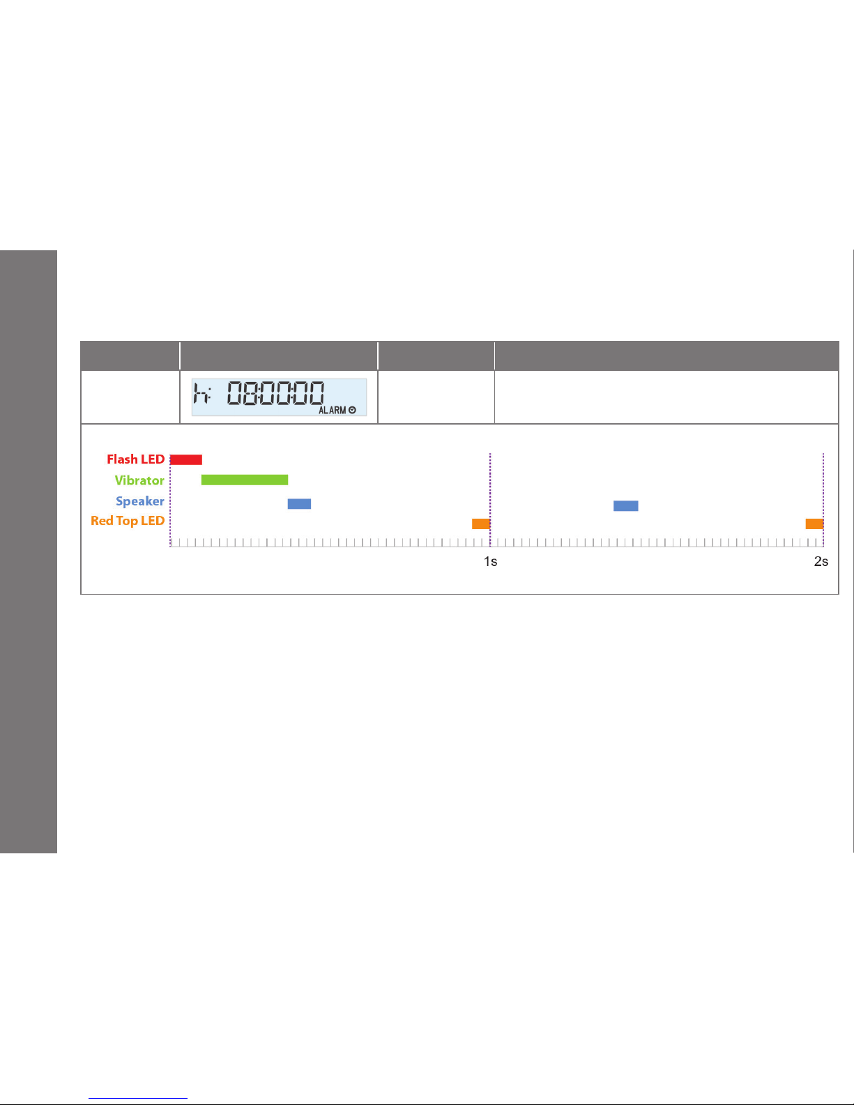
5.3 Time Alarm
Alarm Type Display Speaker Flash LED, Vibrator and Top Red LED
Time Alarm
1 short beep
every second
FLASH LED 1 ash every 10 seconds
VIBRATOR 1 vibration every 10 seconds
TOP LED 1 red ash every second
Alarms
Page 26
-26-
151153EN-G
DMC 3000 User's Guide
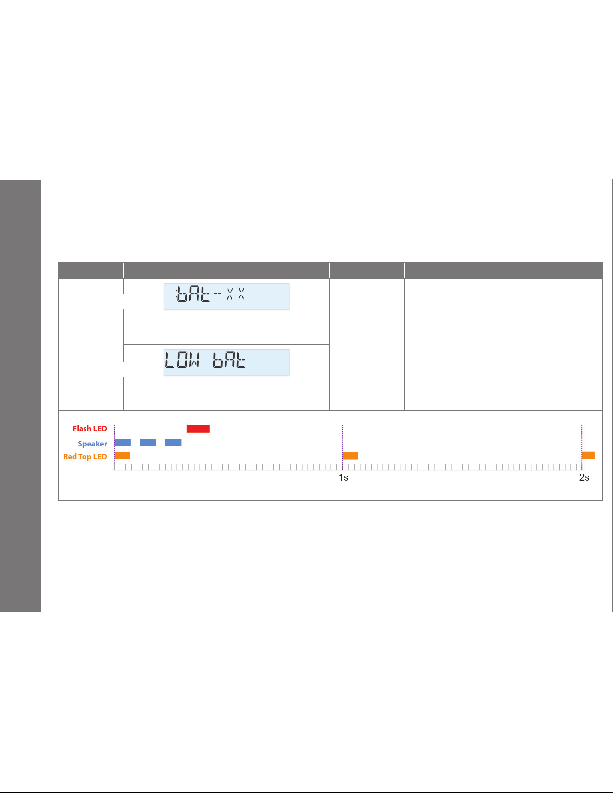
Alarm Type Display Speaker Flash LED, Vibrator and Top Red LED
Low Battery
xx is the remaining time in Run mode from 9 to 1 hours.
Then the DMC goes into power loss for 90 seconds and
then turns o.
3 short beeps
every 10 minutes
FLASH LED
1 ash every 10 minutes
NO VIBRATOR
TOP LED
1 red ash every second
After 72 hours of low battery in PAUSE mode, the DMC
goes into power loss during 90 seconds and then turns
o.
In Run
In Pause
5.4 Low Battery
The DMC 3000 emits a low battery alarm if the battery voltage drops below 1.2 V.
Alarms
Page 27
-27-
151153EN-G
DMC 3000 User's Guide
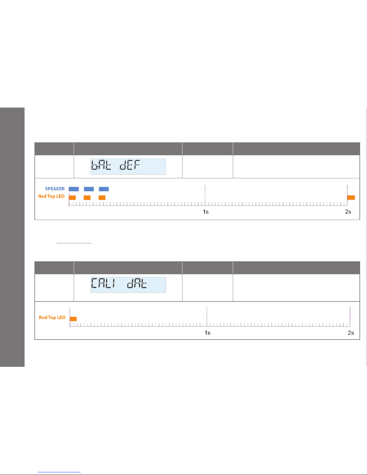
Alarm Type Display Speaker Flash LED, Vibrator and Top Red LED
Power Loss
3 short beeps
every 10 seconds
NO FLASH LED
NO VIBRATOR
TOP LED 3 red ashes every 2 seconds
Alarm Type Display Speaker Flash LED, Vibrator and Top Red LED
Minor Fault
Dosimeter needs a new calibration.
none
NO FLASH LED
NO VIBRATOR
TOP LED only 1 red ash
5.5 Power Loss (after low battery)
5.6.1 Minor Fault
If the calibration due date is exceeded, an alarm message is displayed.
Alarms
5.6 Faults
Page 28
-28-
151153EN-G
DMC 3000 User's Guide
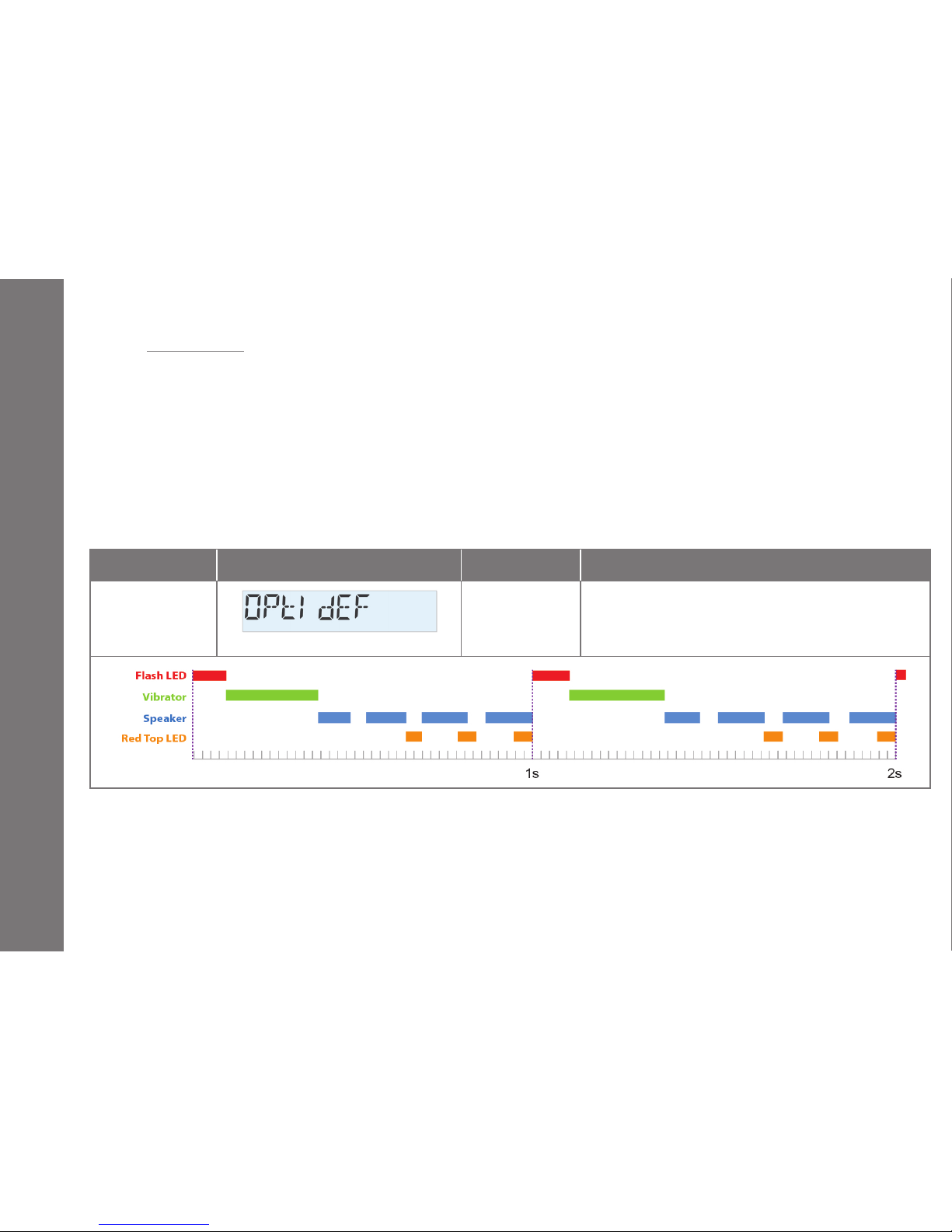
Alarm Type Display Speaker Flash LED, Vibrator and Top Red LED
Major Fault
(Asic, EEPROM,
Detection, Data
Integrity) (*)
4 beeps
every second
FLASH LED 1 ash every second
VIBRATOR 1 vibration every second
TOP LED 3 red ashes every second
Alarms
5.6.2 Major Faults
The DMC 3000 conducts periodic self tests every 10 minutes in Run, Pause and Sleep modes. Most of the tests
are also performed every second in Run mode. All the main functions are controlled by the microcontroller and
all the data, parameters and congurations integrity are protected by the CRC16.
The calibrations and algorithm parameters are protected by the CRC16 and saved inside a specic and dedicated EEPROM. The dierent DC voltages on the electronic board are periodically measured and controlled.
If a fault is detected, an alarm is generated and a message is alternately shown with the measure on the display.
A major fault prevents the DMC 3000 from going into RUN mode
(*) See 5.6.3 for the list of faults and solutions to perform
Page 29
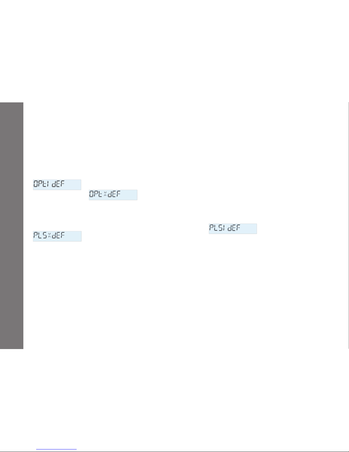
-29-
151153EN-G
DMC 3000 User's Guide
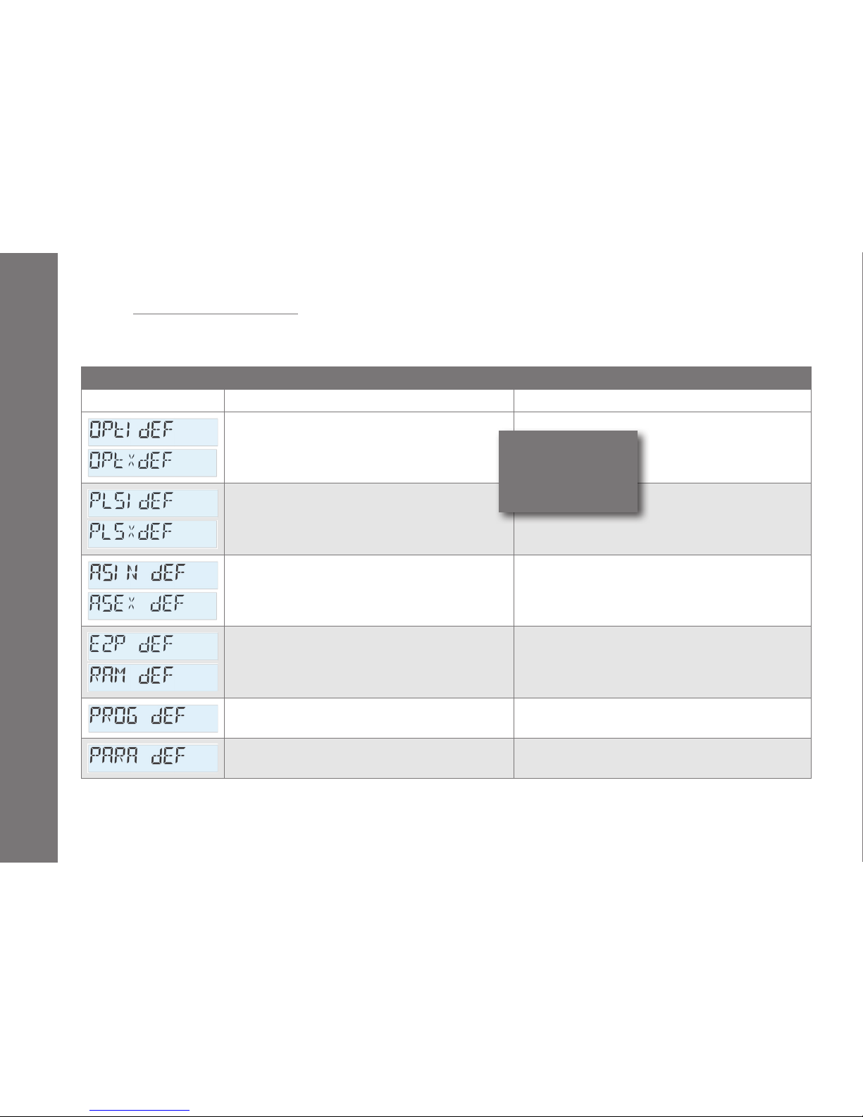
Major Faults
Display Cause Solution
Physical problem related to the detection circuit and
detectors (optical check) of the DMC 3000 (OPtI dEF)
or of the module (OPtX dEF).
Contact Mirion for verication.
Physical problem related to the detection circuit and
detectors (no pulse during the last check period)
from the DMC 3000 (PLSi dEF) or from the module (PLSX
dEF).
Conrm the default with a source of radiation.
If the fault persists, contact Mirion for verication.
Physical problem related to the detection circuit (no communication with the microprocessor) of the DMC 3000
(ASIN dEF) or of the module (ASEX dEF).
When ASEX dEF occurs, check the connection to the
module. Make sure that no disconnection can occur while
in Run mode.
If the fault persists, contact Mirion for verication.
Problems accessing the data saved in memory. Contact Mirion for verication.
Problems accessing the software program saved in
memory.
Contact Mirion for verication.
Problem with the parameters' data integrity saved in
memory.
Contact Mirion for verication.
5.6.3 Troubleshooting Guide
The following troubleshooting guide describes the dosimeter's major fault messages and how to manage them.
For safety reasons, the DMC 3000 cannot be set to Run mode when a major fault is displayed in Pause mode.
Alarms
See § 5.5.4 Optical test
and pulse test
Page 30
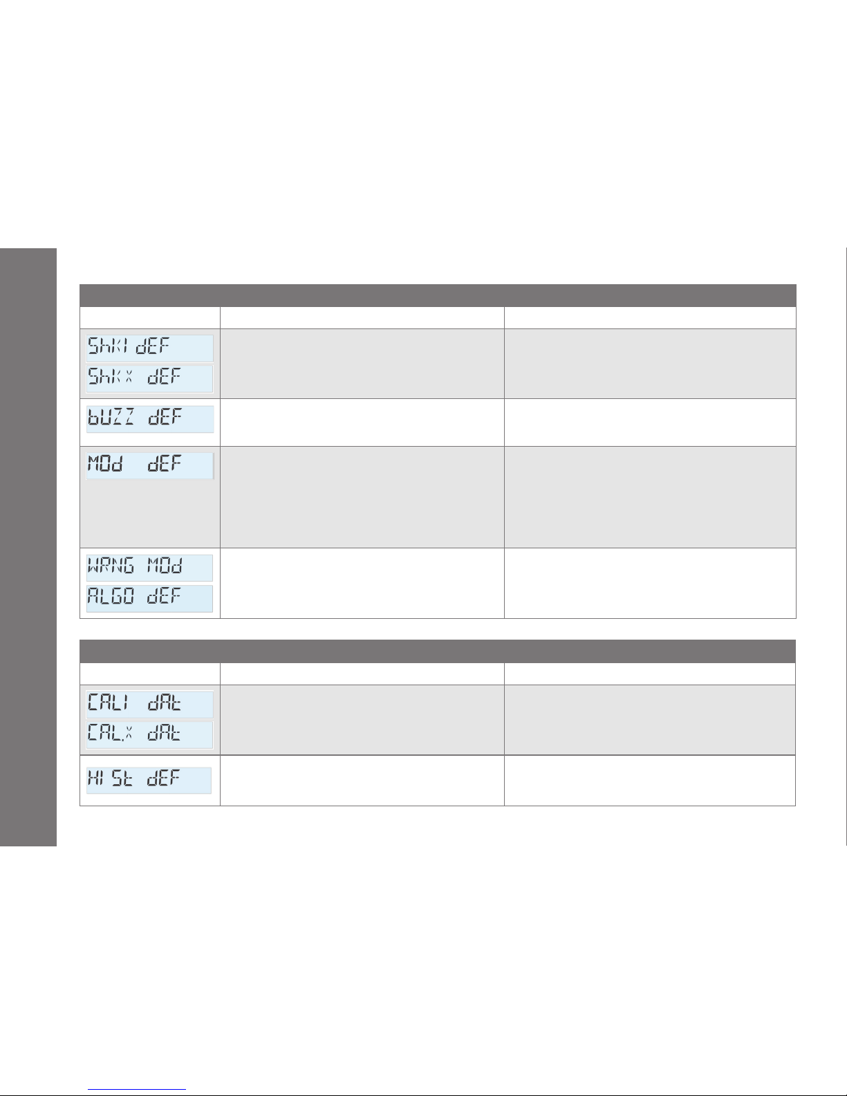
-30-
151153EN-G
DMC 3000 User's Guide
Major Faults
Display Cause Solution
Pulse counting limitation due to an amount of mechanical shocks or electromagnetic interference on the
DMC3000 (ShKI dEF) or on the module (ShKX dEF).
Conrm whether or not this fault occurs with "normal use"
(no high mechanical or electromagnetic stress).
Contact Mirion for verication.
Electrical problem related to the speaker circuit
(DC 3V or audio frequency).
Verify that the speaker cavity is not obstructed and the
battery voltage is not too low (low battery fault).
Contact Mirion for verication.
Electrical problem or conguration problem of the
DMC3000 and its link to the module.
Put the DMC 3000 in pause then do a "Detach Module"
with DMCUser software, or remove the battery to remove
the faults.
Check that DMC 3000 rmware is more recent than V.7.
Check the connection and connection board then connect
the module.
See §2.2 for compatibility, see §10 for Add-on Modules.
The module is not recognized by the DMC 3000.
Check the conguration of the DMC 3000 that could accept
this type of module.
Minor Faults
Display Cause Solution
Exceeded due date of calibration
Perform a calibration check on DMC 3000 (CALi dAt) or on
the module (CALX dAt).
Missing bit/pointer in the histogram
Verify that the battery voltage is sucient and perform an
entry with DMCUser software.
If the fault persists, contact Mirion for verication.
Alarms
Page 31
-31-
151153EN-G
DMC 3000 User's Guide
Alarms
5.6.4 Optical Test and pulse Test
For a complete check of the gamma and X-ray detection capabilities, two complementary tests are performed.
First, a periodic optical test is performed every 10 minutes in Pause, Sleep and Run modes by generating light
pulses on all detectors to simulate gamma photons, beta or neutron radiation.
If the number of pulses detected is less than expected on the detection circuit of the DMC 3000, a fault
is displayed, indicating that the detection function is no longer operational. If the module
detection circuit fail,
is displayed.
In addition to the optical test, the background counting is veried. If the duration between two pulses is
too long compared to the statistical time calculation, then a fault
(DMC 3000 fault) or
(module fault) is displayed.
Page 32
-32-
151153EN-G
DMC 3000 User's Guide
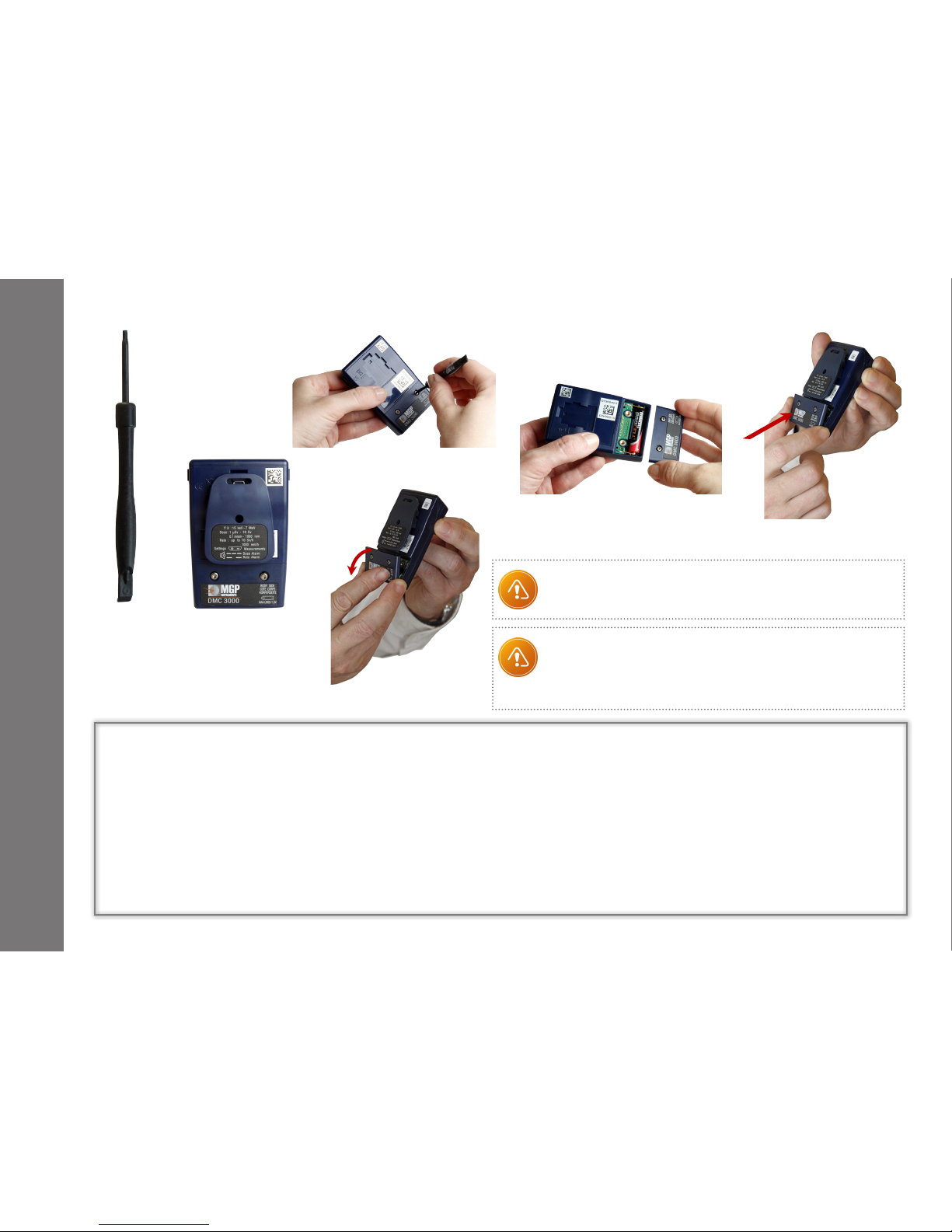
6- Battery Replacement
(1)
-
+
(3)
(4)
(5)
(2)
(6)
Take care to not damage the gasket. We recommend to
replace the battery cover every ve years or if gasket is
damage. For proper sealing, equal and proper torque
should be applied on both screws.
When engaging the battery in the compartment, make
sure to follow the polarity indicated by the drawing in
the battery compartment.
Battery Type:
Alkaline 1.5 V AAA LR03
Screw Type:
Torx N° 8, ISO 14583
Engage rst the - side of the AAA battery on the com-
partment (5) by compressing the spring contact and
push the battery into its compartment.
Engage the battery cover bottom side rst (6) and
rotate.
Hand tight with the tool provided (1) at 0.25 to
0.35 Nm (2.2 to 3.1 in.Lb).
Remove the belt clip (2). (See §7.1)
Not necessary with standard or front facing clip.
Unscrew the two screws (3) with the
screwdriver provided with your DMC 3000 (1).
Rotate and remove the battery cover (4).
Disengage the AAA battery on the + side rst (5).
Removal Replacement
Page 33
-33-
151153EN-G
DMC 3000 User's Guide
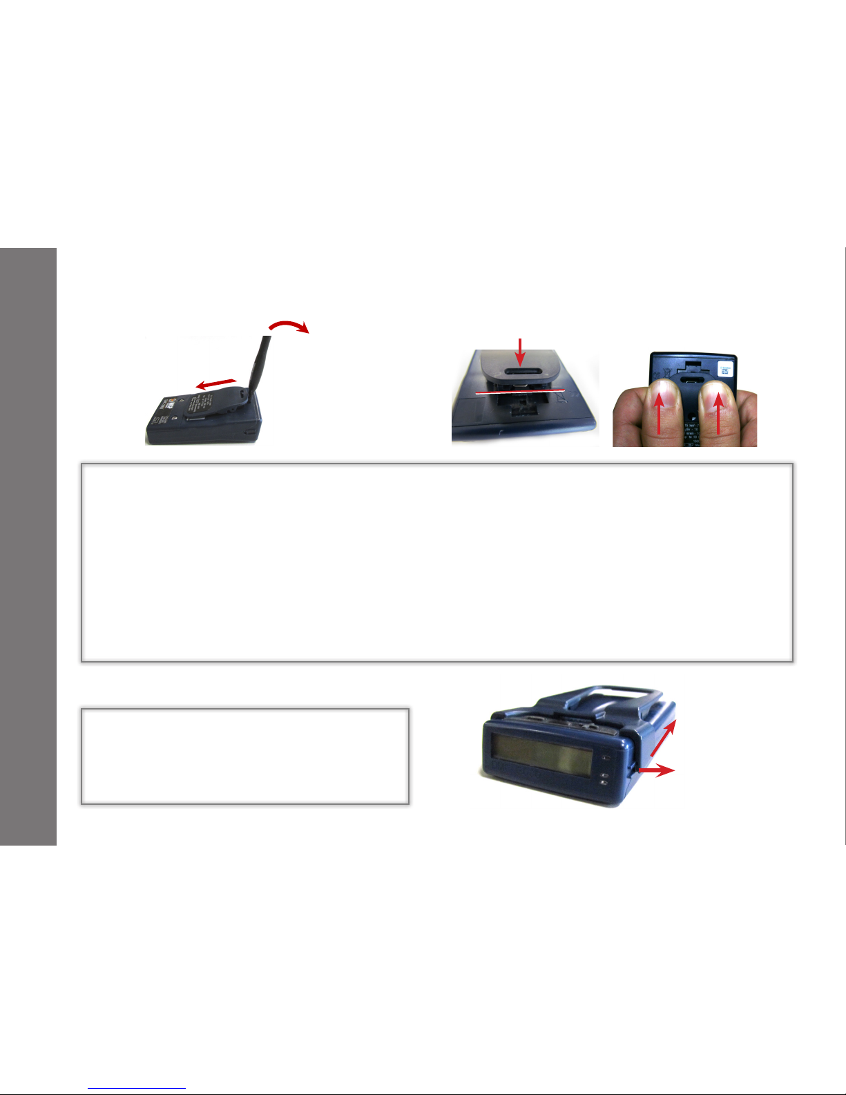
7- Clip Replacement
Before removing/installing the clip, make
sure that the battery cover is in place.
Use the screwdriver/clip removal tool
provided with your DMC 3000.
Engage the head of the tool on the top of
the clip as shown.
Lift the clip lug of the clip (1) while sliding
down the clip (2).
Engage the clip on the middle of its location(3).
Press the clip strongly with the thumbs (4) until
the spring is compressed then slide up the
clip(5) until locked (click sound).
Removal
7.1 Standard or Belt Clip
7.2 Front Facing Clip
Lift up (6) on both sides and disengage the
clip from the attachment guide (7).
Removal / Replacement
Replacement
(1)
(2)
(3)
(5)
(6)
(7)
(4)
Page 34

-34-
151153EN-G
DMC 3000 User's Guide
8- Manual Calibration & Maintenance
8.1 Manual Calibration
This method can be used for the DMC 3000 itself and for any attached module. For attached module, as the
calibration parameters are saved on the module itself, Module may be calibrated on any compatible DMC
3000 as a host for the calibration process
One specic eciency coecient multiplier is available for each type of measurement (Hp(10) gamma,
Hp(0,07) X + Gamma, Hp(0,07), Beta Hp(10) neutron).
Use the proper source depending on the type of measurement.
Hereafter is the method for the Hp(10) X+Gamma calibration:
Expose the dosimeter with a gamma source
137
Cs (note) to a minimum dose of 500 µSv, that is the expected
dose and read on the dosimeter display the "Read Dose."
Look up the Hp(10) Gamma Eciency Coecient Multiplier using
dmc
User software. This calibration factor
is called "K OLD".
Determine the new Hp(10) Gamma Eciency Coecient Multiplier "K NEW" using the following equation:
K NEW = K OLD x Read dose / Expected dose.
Turn o the dosimeter and set the Hp(10) Gamma Eciency Coecient Multiplier to the new value
"K NEW" using
dmc
User software.
Expose the dosimeter with the same source and check that the response of the dosimeter is within the limit.
Note:
The DMC 3000 is equipped with 2 detectors, one for high energy gamma and >50 kev X-ray and a second detector for low energy
X-ray down to 15 kev. Calibration with a Gamma source (
137
Cs or 60Co) or Gamma source and low energy X-ray may be conside-
red based on service environment. Mirion Technologies provides a calibration check at 3 energy levels (16 keV X-rays,
241
Am and
137
Cs) and 60Co on request, in accordance with ISO/IEC 17025 (COFRAC accreditation Nber 2-1663).
- In G3 protocol Hp(10) Gamma Eciency Coecient Multiplier is set at 1.00 in factory.
- Decreasing the Hp(10) Eciency Coecient in G2 protocol or Hp(10) Gamma Eciency Coecient Multiplier in G3 protocol will increase
the DMC 3000 response.
Page 35

-35-
151153EN-G
DMC 3000 User's Guide
Manual Calibration & Maintenance
8.2 Maintenance
Mirion Technologies recommends to perform a complete check at least every year, including:
Calibration check
Display, top and ashing LEDs inspection
Check on wake from sleep, the dosimeter will perform a self test in which the following can be observed: the
speaker will chirp once, the front ash LED and the three (3) top LEDs (red, green, blue) will briey illuminate,
all display segments will light and the back light will turn on
Speaker check (turn on your DMC with rate warning set point at "0")
Note:
The DMC 3000 is provided with an initial factory calibration traceable to international reference standards.
Mirion recommends an annual calibration check; although the re-calibration interval may be determined by the customer based
on service environment, frequency of use and requirements dened by local regulations.
Page 36
-36-
151153EN-G
DMC 3000 User's Guide
9- Technical Characteristics
9.1 Physical Characteristics
Compliant with IEC 61526 Ed. 3, ANSI 42.20 (*)
(*) Isotropy at
241
Am and
137
Cs with angle ± 75°
Measurement and display:
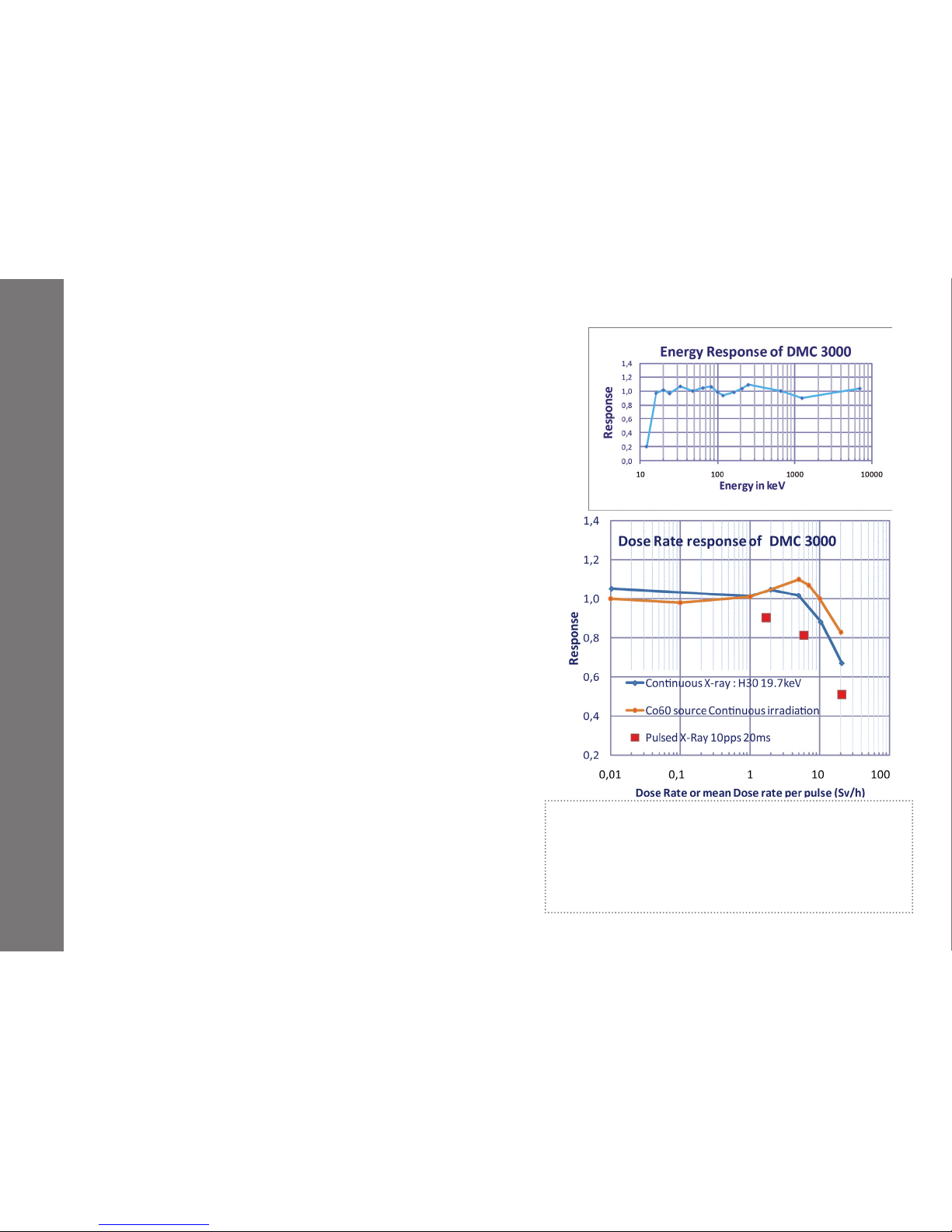
X-ray and gamma energy range: 15 keV to 7 MeV
Energy response better than ± 20% from 16 keV to 7 MeV
(typically ± 10%)
Accuracy Hp(10):
≤ ± 10% (16 keV)
≤ ± 10% (
241
Am)
≤ ± 5% (
137
Cs)
≤ ± 10% (
60
Co)
Display units: mSv, µSv, or mrem
Display dose: 1 µSv to 10 Sv (0.1 mrem to 1000 rem)
Display rate:
0.01 mSv/h to 10 Sv/h (1 mrem/h to 1000 rem/h)
or 0.001 mSv/h to 10 Sv/h (0.1 mrem/h to 1000 rem/h)
(extended option(**))
Measurement range:
1 µSv to 10 Sv (0.1 mrem to 1000 rem)
0.1 µSv/h to 20 Sv/h (0.01 mrem/h to 2000 rem/h)
Saturation indication : above 10 Sv (1000 rem)
or 10 Sv/h (1000 rem/h)
Dose rate linearity:
≤ ± 20 % up to 10 Sv/h (1000 rem/h) (Co and X H30 20 keV)
(**) - Mandatory if rate alarms are set below 50 µSv/h
(5 mrem/h) in order to display rate with better accuracy, if
fast response time for rate alarm is not required.
- Recommended for rate alarms settings below
100 µSv/h (10 mrem/h), if fast response time for rate alarm
is not required.
Page 37

-37-
151153EN-G
DMC 3000 User's Guide
9.2 Electrical Characteristics
Standard AAA (LR03) 1.5 V Alkaline battery
9 calendar month battery life (typical, 8 h per day, 5 days per week in Run mode, without excessive alarms (*)
2500 h battery life in continuous run, without excessive alarm (*)
(*) 0.2% of the time in alarm
9.3 Mechanical Characteristics
Rugged, high impact polycarbonate-ABS case
Dimensions: Typ. 86 x 56 x 21 mm (3.4 x 2.2 x 0.8 in) without clip ; Max 60 x 88 x 29 mm with clip
Weight with alkaline battery and standard clip: < 88 g (3.1 oz)
Worn with replaceable clips (2 dierent style back clips or one front-facing clip for DMC worn inside the pocket)
Technical Characteristics
Page 38

-38-
151153EN-G
DMC 3000 User's Guide
9.4 Environmental Characteristics
Temperature range: -10°C to 50°C (14°F to 122°F): deviation in response less than ±5%
Relative humidity: <95% RH at 35°C (95°F)
Storage: -20°C to 71°C (-4°F to 160°F) without battery
Shock, vibration and drop resistant (1.5 meter on concrete)
Waterproof IP67 1m (39 in) during 1 hour
EMC: complies and exceeds standards by a large margin ( compliant, certicate number 153720)
MIL STD 461F RS103 (pulsed electric eld): exceeds 200 V/m from 10 kHz to 5 GHz
MIL STD 461F RS101 (magnetic eld 30 Hz to 100 kHz)
9.5 Factory Calibration and verification
Approved under ISO/IEC 17025 (COFRAC accreditation Nber 2-1663 ) with three energy references:
16 keV (X); ~ 0,7 mSv/h with ± 8.5% extended uncertainty k=2
59.3 keV (
241
Am); ~ 23 mSv/h with ±5% extended uncertainty k=2
662 keV (
137
Cs); ~ 24 mSv/h with ± 5% extended uncertainty k=2
only on request: 1.2 MeV (
60
Co) ~ 5,5 mSv/h with ± 6.5% extended uncertainty k=2
Technical Characteristics
Page 39

-39-
151153EN-G
DMC 3000 User's Guide
9.6 Functional Characteristics
Indicators:
Large-format, backlit, high-contrast LCD display (8 alphanumeric characters + symbols)
Indicator lights (red, green and blue LEDs)
Flash red alarm LED
Vibrator
2 selection buttons for acknowledging warnings, viewing parameters and measurements (data)
Alarming speaker with level of 85 dB (A) typical (> 90 dB (C) peak) at 30 cm (11.8 in),
frequency < 5000 Hz
Alarms:
Precision: the alarm is triggered when the measured value reaches the corresponding alarm threshold value
Dose alarm: two thresholds (alarm and warning). Can be adjusted over the entire display range
(only the warning can be acknowledged)
Dose rate alarm: two thresholds (alarm and warning). Can be adjusted over the entire display range
(only the warning can be acknowledged)
Acknowledgment of warnings is accomplished by pressing and holding either push button for at least 3 seconds.
Checks:
Periodic detector test (every 10 minutes) for both low and high energy detectors
Internal data integrity check with CRC16
Periodic battery test (every 10 minutes)
Component test (integrated circuit, memories)
Specic and dedicated EEPROM for calibration and algorithm parameters
Technical Characteristics
Page 40
-40-
151153EN-G
DMC 3000 User's Guide
Memory:
Data storage in EEPROM for more than 10 years
Historical record of dose increments and events
RTC for date stamping information
3800 history events at programmable intervals of 10 seconds, 1 minute, 10 minutes, 1 hour or 24 hours
in G2 protocol
Up to 10 days of record with 1 minute interval in G3 protocol with average ambiant rate of 5 µSv/h.
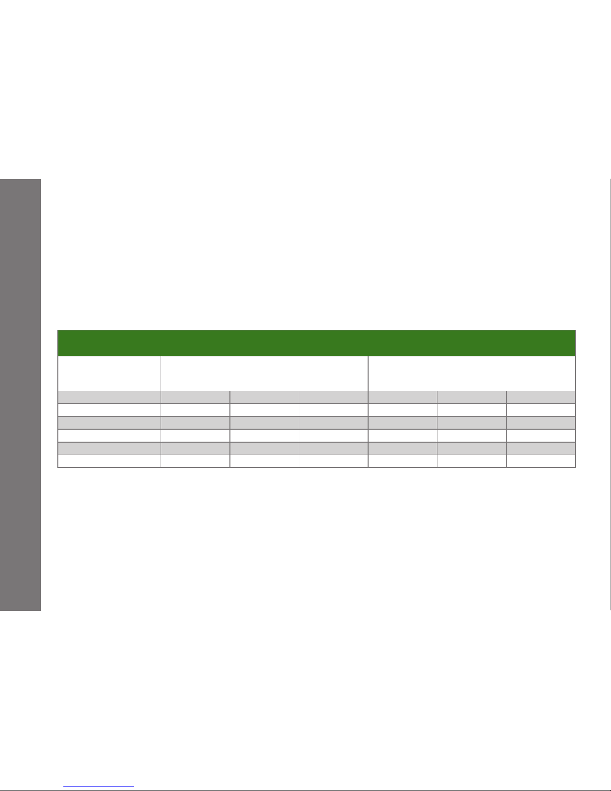
See table below:
9.7 Environment
In accordance with European regulation (Directive DEEE 2002-96-CE), dosimeters should not be thrown out
with non-sorted waste, but must be selectively collected.
The batteries should not be recharged or thrown in re.
Technical Characteristics
Total duration of record without overlap
(DMC 3000 in G3 protocol (rmware V7), with/without Neutron or Beta Hp(0,07) Module) (**)
Interval of dose stamp
Minimum Value : one increment of dose equal
or greater than 1µSv each interval in Primary and
secondary (if module) doses
Average Value: one increment of dose equal or
greater than 1µSv each 10 interval in Primary and
secondary (if module) doses
Average rate Without Module With Module (*) Average rate Without Module With Module (*)
10 seconds 360 µSv/h 4 hours 2 hours 32 µSv/h 42 hours 19 hours
1 minute 60 µSv/h 23 hours 10 hours 6 µSv/h 10 days 5 days
10 minutes 6 µSv/h 10 days 4 days 55 nSv/h 100 days 50 days
1 hour 1 µSv/h 60 days 26 days 10 nSv/h 640 days 290 days
24 hours 40 nSv/h 1400 days 630 days 4 nSv/h 15 000 days 7 000 days
(*) with Hp(0,07) Beta Module (worst case)
(**) with raw counts
Page 41
-41-
151153EN-G
DMC 3000 User's Guide
Technical Characteristics
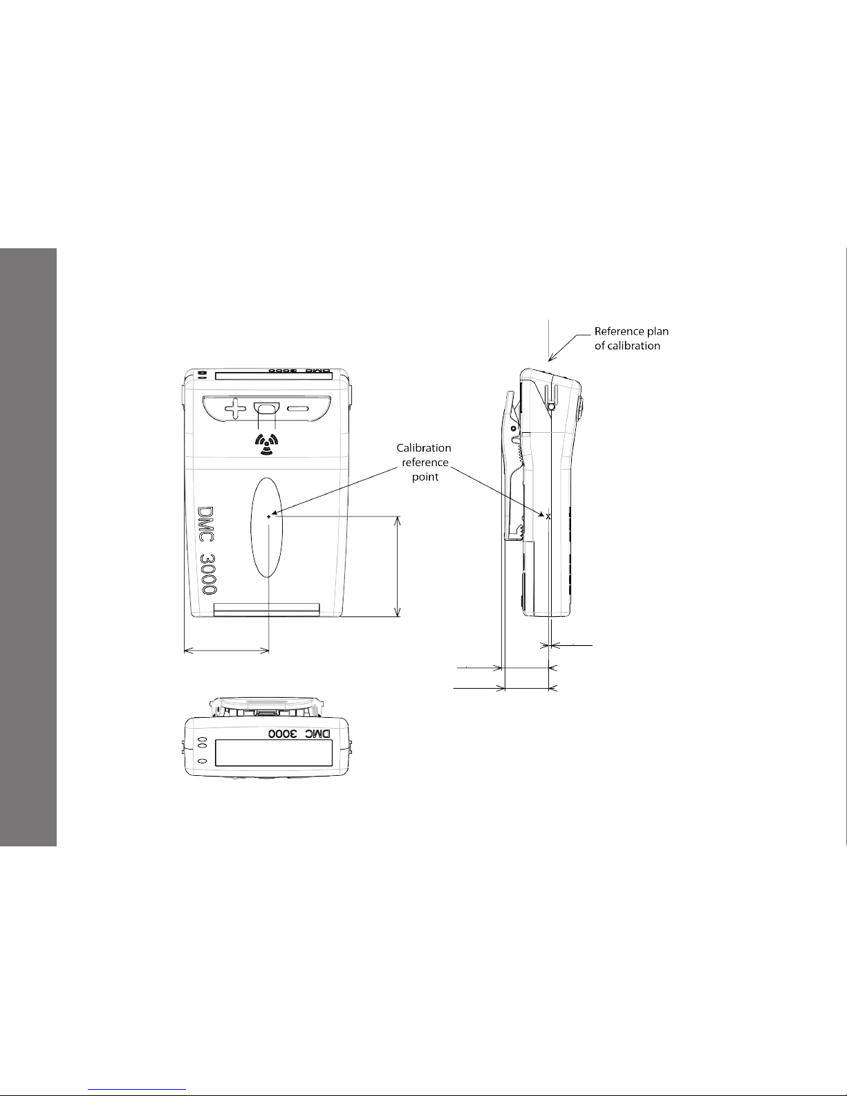
9.8 Reference point of calibration
Note: Dimensions in millimeters
29,73
35,35
16,63
0,95
15,43
Page 42
-42-
151153EN-G
DMC 3000 User's Guide
10- Add-on Modules
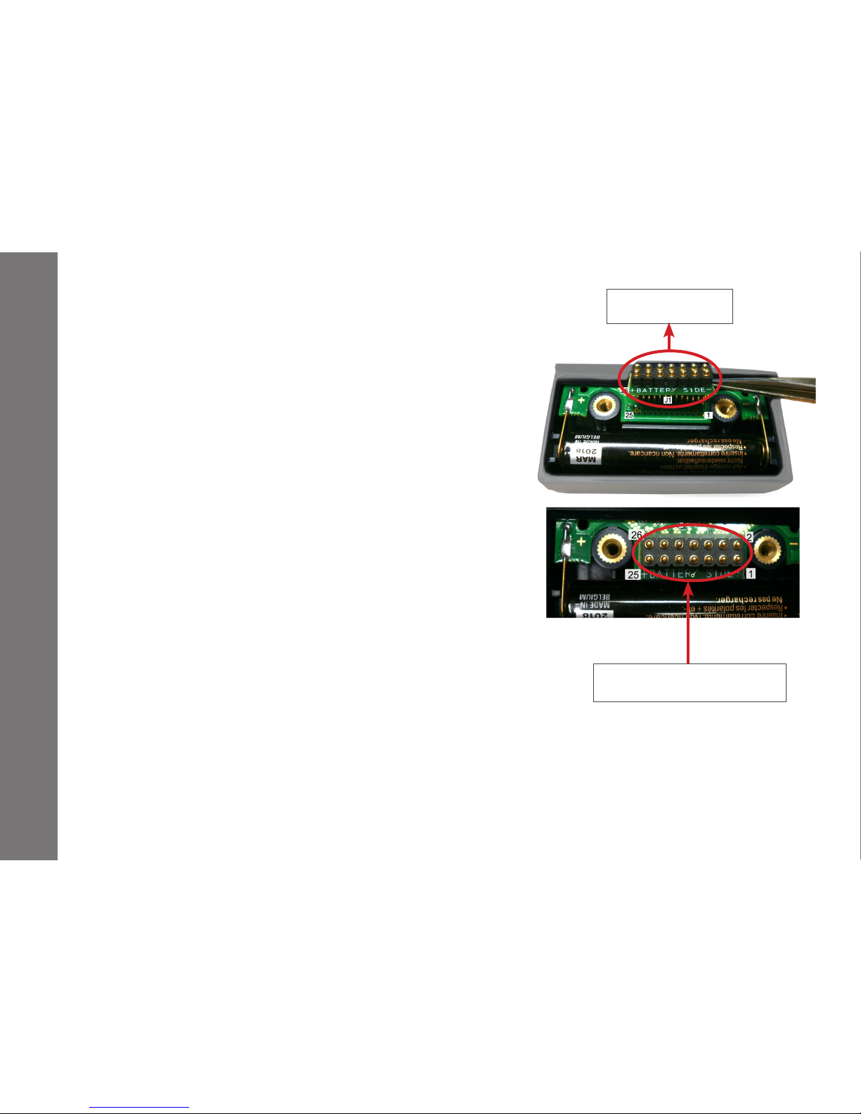
The DMC 3000 is provided with an extension capability at the
bottom of the case.
For this purpose, a 26-pin connector allows connection for the
following:
Bidirectional serial communication
Report alarm signal
Detection module (Hp(10) Neutron, Hp(0,07) beta, etc.)
or Telemetry module (see §2.2)
External power
Before connecting any add-on module, it is necessary to equip
your DMC 3000 with a 26-pin connector, ref. 00153458 on top of the
DMC3000 board and your DMC 3000 must be in Pause.
10.1 Dedicated documentation
DOC003284 for the beta Hp(0,07) module
DOC003285 for the neutron Hp(10) module
15-00100 for the telemetry module
DOC006094 for the PRD module
10.2 Module Attachment
Ensure dosimeter is in Pause mode (i.e not in Run or Sleep mode)
Refer to the dedicated documentation to install the module
26-pin connector
ref. 00153458
Make sure the connecting
board is correctly oriented
Page 43
-43-
151153EN-G
DMC 3000 User's Guide
Add-on Modules
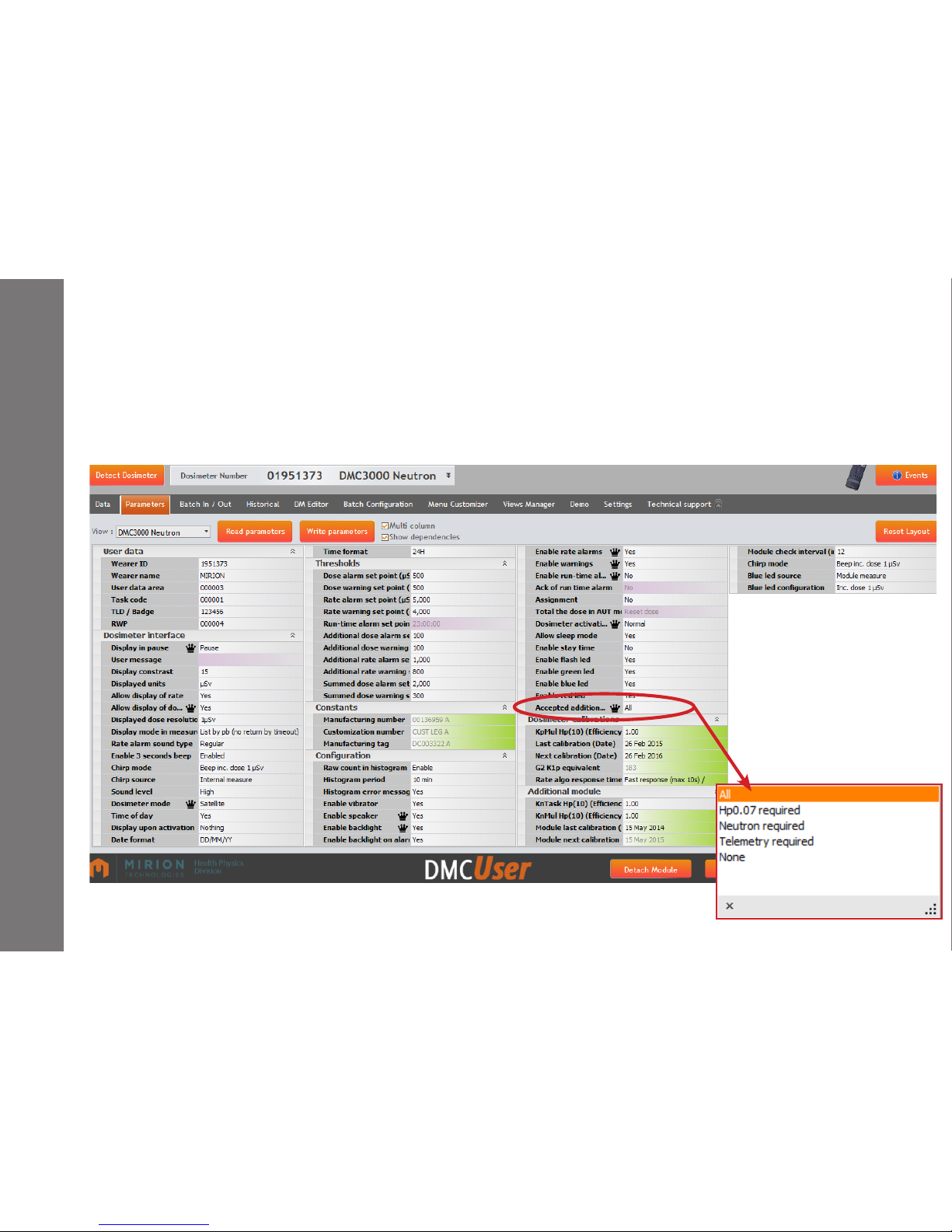
10.3 DMCUser parameters
DMCUser parameter settings shall be congured as follows.
For "accepted external module" select "ALL" or "telemetry required" or "Hp(0.07) required" or "neutron requi-
red" if a specic module is needed.
Telemetry module can be enable/disable by the user, select "enable external module".
Page 44
-44-
151153EN-G
DMC 3000 User's Guide
Add-on Modules
10.4 Module Detachment
For detachment, ensure the dosimeter is in pause Mode.
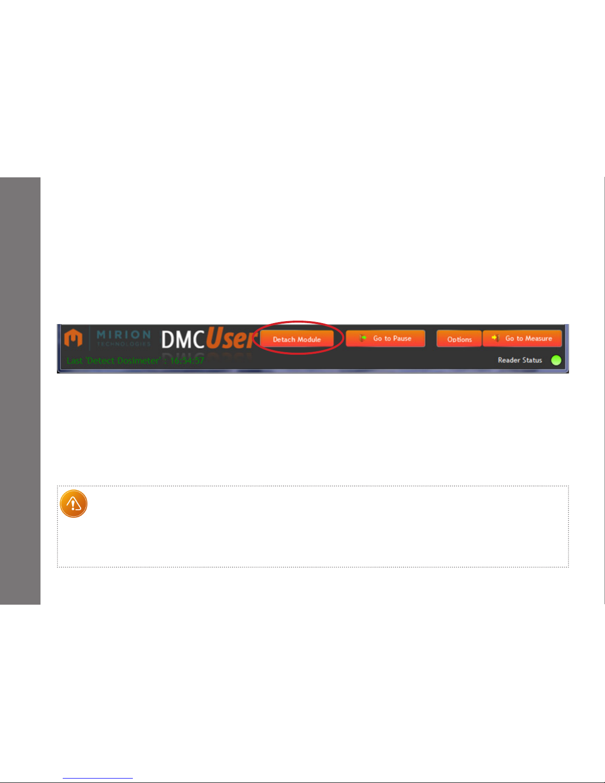
To clear “MOD dEf” alert indication from dosimeter display, it is recommended to perform the following:
Select “Detach module” in the bottom of DMCUser’s window or remove the dosimeter’s battery and then put it
immediately back into place.
Note :
If the external module conguration is with " Module required" (for example "Neutron required" the Detach Module action
cannot clear the "MOD dEf" alert indication.
Due to current being present on the pins when the DMC 3000 is energized, take care when attaching new modules or adapter
board not to short any of the pins.
The add-on module must be attached or removed only when the DMC 3000 is in PAUSE.
Page 45
-45-
151153EN-G
DMC 3000 User's Guide
Spare Parts
Alkaline battery (x10) 1.5V AAA (LR03) 153 634
Battery cover - full set (x10) 153 651
Standard clip (x25) 153 631
Belt clip (x10) 153 632
Front facing clip (x10) 153 633
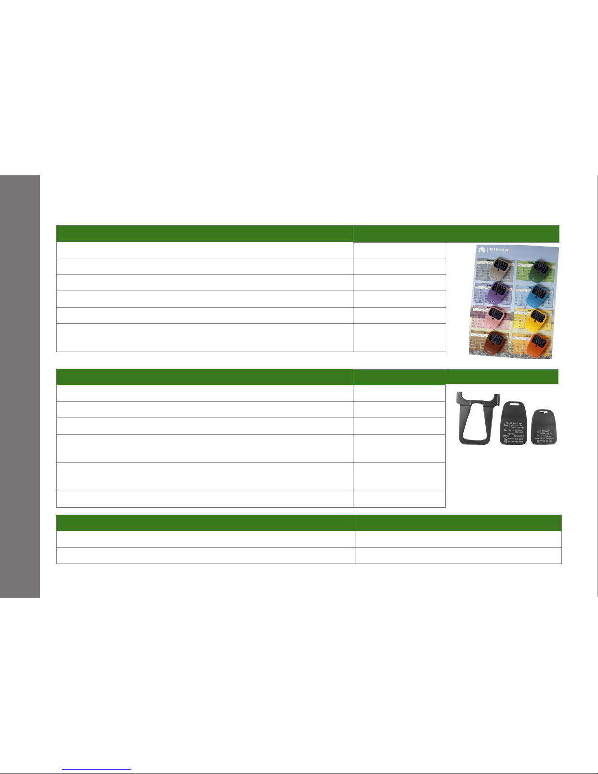
Set of colored standard clips (x25 in each of the 12 colors (*) =
total of 300 clips)
153 650
Accessories
Screwdriver for changing battery/ clip (x10) 153 630
26-pin connector 00153458 (x10) for add-on module 153 635
Telemetry Module (includes a 26-pin connector) ATR000053
Hp(10) Neutron Module in individual box
(includes a 26-pin connector)
NOM001229
Hp(0,07) Beta Module in individual box
(includes a 26-pin connector)
NOM001230
PRD Module in individual box (includes a 26-pin connector) NOM002153
Racks Mirion Technologies Reference Number
Wall mounted rack of 40 DMC 3000 (*) 172 609
Wall mounted rack of 10 DMC 3000 (**) 166 010
(*) Available colors are: beige, white, black, red, yellow, purple, orange, brown, pink, grey, green and blue.
The items listed below can be ordered from Mirion Technologies.
(*) =compatible with DMC 2000S and GN, can be xed at the same location as the previous 40 DMC 2000S/GN reference 118 938
(**) =compatible with DMC 2000S and GN
11- Accessories References
Mirion Technologies Reference Number
Mirion Technologies Reference Number
Front facing
clip
Belt
clip
Standard
clip
Page 46

-46-
151153EN-G
DMC 3000 User's Guide
12- CE Certificate
Page 47
-47-
151153EN-G
DMC 3000 User's Guide
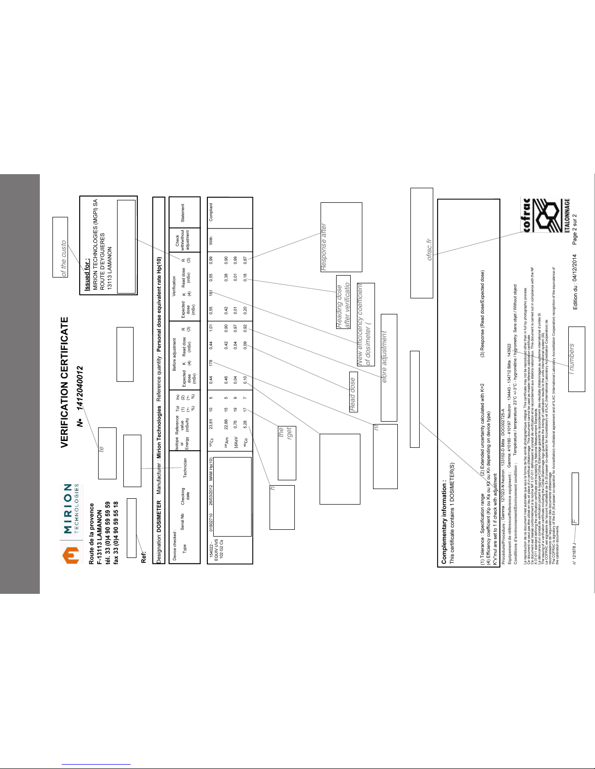
13- Verification Certificate
Our references
Date and Name
of operator
The Certificate can
be with or without the
Hp(0.07) calibration for
X+Gamma depending on
the version
Procedure's reference number
Note: calibration target could
be different than 1
Forms reference
Serial numbers of
the calibrators used.
Name and address
of the customer
Certificate
single number
Filled in when
adjustment
Rate at which
the dosimeter
is irradiated
Tolerance on the
calibration target
Efficiency coefficient
of the dosimeter as
found
Read dose
Response after
adjustment or
verification
R = Read dose /
Expected dose
Reading dose
after verification
Response before adjustment
R = Read dose / Expected dose
New efficicency coefficient
of dosimeter (as left)
Expected dose in
regard of exposure
time (=expected dose
on the dosimeter for a
response (R) at 1)
{
Logo of the accreditation organism
Accreditation #: 2.1663
See www.cofrac.fr
Page 48

-48-
151153EN-G
DMC 3000 User's Guide
Notes :
Page 49

-49-
151153EN-G
DMC 3000 User's Guide
Notes :
Page 50

-50-
151153EN-G
DMC 3000 User's Guide
Notes :
Page 51
-51-
151153EN-G
DMC 3000 User's Guide
Page 52

151153EN-G
www.mirion.com
DMC 3000 User's Guide
France
Mirion Technologies (MGPI) S.A.
Lieu-dit Calès - Route d’Eyguières,
F-13113 Lamanon
France
Tel. +33 (0)4 90 59 59 59
Fax. +33 (0)4 90 59 55 18
Germany
Mirion Technologies (RADOS) GmbH
Ruhrstrass 49
DE-22761 Hamburg
Germany
Tel. +49 40 851 93-0
Fax. +49 40 851 93 256
Finland
Mirion Technologies (RADOS) Oy
Mustionkatu 2, PO Box 506
FIN-20101 Turku
Finland
Tel. +358 2 4684 600
Fax. +358 2 4684 601
USA
Mirion Technologies (MGPI), Inc.
5000 Highlands Parkway Suite 150
Smyrna, GA 30082
USA
Tel. +1 770-432-2744
Fax. +1 770432 9179
China
Mirion Commercial (Beijing) Co., Ltd. Shanghai
Jiangchang Commercial Branch
76 & 78 Jiang Chang No. 3
Rd. 801 & 807
Shanghai 200436
China
Tel. +86-21-6180 6920
Fax. +86 21 6180 6924
 Loading...