

Page 1
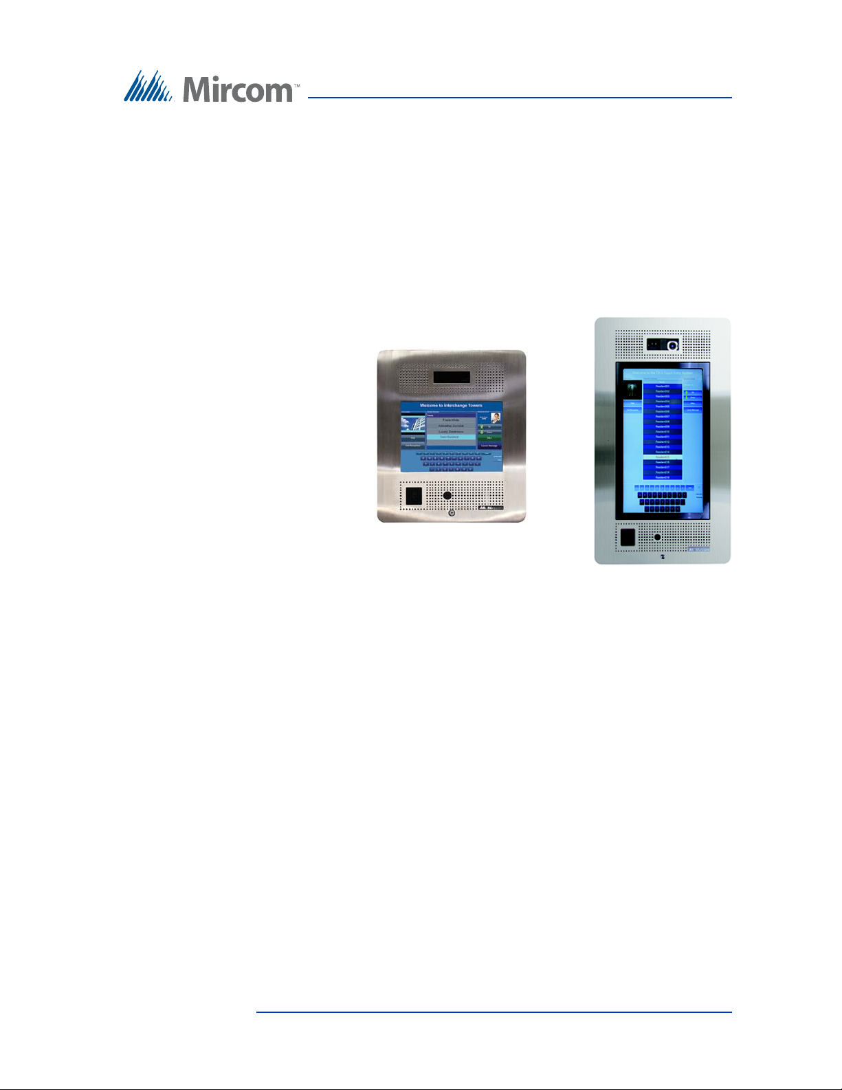
TX3 Series
Touch Screen
Installation Manual
Version 4.2 TX3 Touch Screen Installation Manual 1 (126)
LT-996 Copyright February 2017
Page 2

Copyright February 2017 Mircom Inc.
All rights reserved.
Mircom Touch Screen Installation Guide v.4.2
This manual, as well as the software described in it, is provided under licence or other agreements
and may be used or copied only in accordance with the terms of such license. The content of this
manual is furnished for informational use only. It is subject to change without notice, and should not
be construed as a commitment by Mircom. Mircom assumes no responsibility or liability for any errors
or inaccuracies that appear in this book.
Except as permitted by such license, no part of this publication may be reproduced, stored in a
retrieval system, transmitted in any form by means electronic, mechanical, using any recorded
media, or any other format without the prior written permission of Mircom.
Microsoft, MS-DOS, Windows, and Windows 2000/NT/XP are either registered trademarks or
trademarks of Microsoft Corporation in the United States and/or other countries.
Mircom
25 Interchange Way
Vaughan, Ontario
L4K 5W3
905.660.4655
Fax:905.660.4113
2 (126) Mircom Version 4.2
LT-996 Copyright February 2017
Page 3

Contents
1 Introduction 8
1.1 TX3 Systems 8
1.2 Features 13
1.3 Touch Screen Sizes and Enclosures 14
1.4 Touch Screen Accessories 15
1.5 Mounting requirements from the 2010 ADA Standards for Accessible
Design 16
1.6 Warranty and Special Notices 17
1.7 About This Manual 17
1.8 Contact Us 18
2 Enclosure Installation 20
2.1 Installing the Enclosures and Touch Screen 21
2.2 Installing TX3-TOUCH-S15-A 22
2.3 Installing TX3-TOUCH-F15-A 25
2.4 Installing TX3-TOUCH-F15-B 28
2.5 Installing TX3-TOUCH-S15-B 30
2.6 Installing TX3-TOUCH-S22 and TX3-TOUCH-F22 32
2.7 Installing TX3-T-KIOSK 37
2.8 Installing TX3-T-KIOSK2 43
2.9 Installing TX3-T-KIOSK3 51
2.10 Installing TX3-TOUCH-K15-A 58
2.11 Installing the Power Supply Enclosure 63
3 Touch Screen System and Setup 67
3.1 Touch Screen System 68
3.2 TX3-TOUCH-K15-A, TX3-TOUCH-F15-A, TX3-TOUCH-S15-A Main Panel,
Boards, and Grounding 71
3.3 TX3-TOUCH-F15-B and TX3-TOUCH-S15-B Inside Door, Boards, and
Grounding 73
3.4 TX3-TOUCH-F22 and TX3-TOUCH-S22 Inside Door, Boards, and
Grounding 76
3.5 Telephone Access Controller Board 80
3.6 Connecting to the External Power Supply 81
3.7 Turning the Touch Screen On and Off 83
3.8 Installing the Postal Lock 84
3.9 Installing the Telephone Lines 84
3.10 Installing Optional Components 84
3.11 Verifying Installed Components 86
3.12 Factory Wiring for Touch Screen Units with MD-1236 88
3.13 Factory Wiring for Touch Screen Units with MD-1105 95
3.14 Beginning Configuration 101
3.15 Installing the P1264 IP camera 102
3.16 Replacing the Display on the 22” Touch Screen 104
3.17 Installing the TX3-P300-HA Card Reader in the 22” Touch Screen 108
Version 4.2 TX3 Touch Screen Installation Manual 3 (126)
LT-996 Copyright 2017
Page 4

3.18 Installing a RB-MD-1093 Two Door Controller Network Board 110
4 Adding Controllers 111
4.1 Adding a Controller 112
5 Specifications 113
5.1 Operating Temperature 113
5.2 Telephone Lines 113
5.3 AC Power Supply 113
5.4 22” Touch Screen Power Consumption 113
5.5 External Power Supply 113
5.6 Door Strikes 113
5.7 Outputs 2-4 114
5.8 Post Office Lock 114
5.9 Tamper Switch 114
5.10 RS-485 TX3-USB-AD Kit 114
5.11 TX3-GPM Guard Phone Module 115
5.12 TX3-CX-1NP 115
Contents
6 Resident Operating Instructions 116
6.1 NSL Resident Operating Instructions 117
6.2 ADC Resident Operating Instructions 119
Warranty & Warning Information 120
Special Notices 123
4 (126) TX3 Touch Screen Installation Manual Version 4.2
LT-996 Copyright 2017
Page 5

List of Figures
Figure 1 TX3 devices on an RS-485 network. 10
Figure 2 TX3 devices connected to an Ethernet TCP/IP network. Devices connected to
an Ethernet network are Master Nodes. 11
Figure 3 TX3 devices connected to a combination Ethernet TCP/IP network with RS-485
subnetworks. 12
Figure 4 TX3-TOUCH-S15-A Surface Mount Back Dimensions (inches) 22
Figure 5 TX3-TOUCH-S15-A Surface Mount Front Dimensions (inches) 23
Figure 6 Touch Screen Surface Mount 24
Figure 7 TX3-TOUCH-F15-A Flush Mount Back Dimensions (inches) 25
Figure 8 TX3-TOUCH-F15-A Flush Mount Front Dimensions (inches) 26
Figure 9 Flush Mount Enclosure 27
Figure 10 TX-TOUCH-F15-B Dimensions 29
Figure 11 TX-TOUCH-F15-B Dimensions 29
Figure 12 TX-TOUCH-S15-B Dimensions 31
Figure 13 TX-TOUCH-S15-B Dimensions 31
Figure 14 Surface mounting the enclosure 32
Figure 15 Flush mounting the enclosure 34
Figure 16 TX3-TOUCH-F22 Dimensions (inches) 35
Figure 17 TX3-TOUCH-S22 Dimensions (inches) 36
Figure 18 22” Touch Screen Dimensions (inches) 37
Figure 19 Components of TX3-T-KIOSK 38
Figure 20 Base Plate Mounting Holes 39
Figure 21 Base Plate Dimensions (inches) 39
Figure 22 Fit the stand on the Base Plate 40
Figure 23 Fit the stand on the Base Plate (from below) 40
Figure 24 Attach the stand to the base plate 41
Figure 25 Attach the 22” Touch Screen to the stand 42
Figure 26 Dimensions of TX3-T-KIOSK2 with TX3-TOUCH-S22 43
Figure 27 Dimensions of TX3-T-KIOSK2 with TX3-TOUCH-S15-B 44
Figure 28 Components of TX3-T-KIOSK2 45
Figure 29 TX3-T-KIOSK2 Dimensions (from below) 46
Figure 30 Fit the stand on the floor bracket 47
Figure 31 Fit the stand on the floor bracket (as seen from below) 47
Figure 32 Attach the stand to the floor bracket 48
Figure 33 Mounting holes 49
Figure 34 Mount TX3-TOUCH-S22 on the stand 49
Figure 35 Mount TX3-TOUCH-S15-B on the stand 50
Figure 36 Dimensions of TX3-T-KIOSK3 51
Figure 37 Components of TX3-T-KIOSK3 52
Figure 38 Floor Bracket Mounting Holes 53
Figure 39 TX3-T-KIOSK3 Dimensions (from below) 53
Figure 40 Fit the stand on the floor bracket 54
Figure 41 Fit the stand on the floor bracket (from below) 54
Figure 42 Mount TX3-TOUCH-S22 on the stand 55
Figure 43 Fit the door on the stand 56
Figure 44 Close-up showing the door fitting on the ledge 56
Figure 45 Swing the door closed 57
Figure 46 Kiosk Dimensions (inches) 58
Version 4.2 TX3 Touch Screen Installation Manual 5 (126)
LT-996 Copyright 2017
Page 6

List of Figures
Figure 47 Reinforcement Bracket with bolts 59
Figure 48 Reinforcement Bracket with nuts 59
Figure 49 Kiosk Base Plate with bolts 60
Figure 50 Kiosk Mounting Holes 60
Figure 51 Base Plate Mounting Holes 61
Figure 52 Base Plate Dimensions (inches) 61
Figure 53 Fitting the Kiosk on the Base Plate 62
Figure 54 Fitting the Kiosk on the Base Plate (from below) 62
Figure 55 Attach the Kiosk to the base plate 63
Figure 56 Inside the Switching Power Supply Box 64
Figure 57 Power Supply Voltage Selection Switch 64
Figure 58 Power Supply Enclosure Dimensions 65
Figure 59 Power Supply Enclosure 66
Figure 60 Single Touch Screen 69
Figure 61 Single Touch Screen with ADC and NSL Lines 70
Figure 62 15” Touch Screen Panel Components 71
Figure 63 Controller Board Panel for 15” Touch Screens 72
Figure 64 TX3-TOUCH-F15-B and TX3-TOUCH-S15-B Inside Door 73
Figure 65 Controller Board Panel for TX3-TOUCH-F15-B and
TX3-TOUCH-S15-B 74
Figure 66 Ground and power terminals 75
Figure 67 Grounding TX3-TOUCH-F15-B and TX3-TOUCH-S15-B 75
Figure 68 TX3-TOUCH-F22 and TX3-TOUCH-S22 Inside Door 77
Figure 69 Controller Board Panel for TX3-TOUCH-F22 and TX3-TOUCH-S22 78
Figure 70 Grounding the 22” Touch Screen 79
Figure 71 Controller Board Connectors - Top 80
Figure 72 Controller Board Connectors - Bottom 81
Figure 73 MD-990 Terminal Block Wiring 82
Figure 74 Connecting additional RS-485 Terminal Connector to the First or Last Node of
Network 85
Figure 75 MD-1236 86
Figure 76 MD-1105 87
Figure 77 Factory connections on MD-1236 for TX3-TOUCH-S15-B and TX3-TOUCH-
F15-B 88
Figure 78 Wiring the Button 89
Figure 79 Factory connections on the telephone access controller board for TX3-TOUCH-
S15-B and TX3-TOUCH-F15-B with MD-1236 89
Figure 80 Factory connections on the PC sub compact board for TX3-TOUCH-S15-B and
TX3-TOUCH-F15-B for MD-1236 90
Figure 81 Display connections on TX3-TOUCH-S15-B and TX3-TOUCH-F15-B for MD-
1236 91
Figure 82 Make sure that the arrow is visible 91
Figure 83 Factory connections on the power supply and audio mixer board (MD-1236) for
TX3-TOUCH-S22 and TX3-TOUCH-F22 92
Figure 84 Wiring the button 92
Figure 85 Factory connections on the telephone access controller board for TX3-TOUCH-
S22 and TX3-TOUCH-F22 for MD-1236 93
Figure 86 Factory connections on the PC sub compact board for TX3-TOUCH-S22 and
TX3-TOUCH-F22 for MD-1236 93
Figure 87 Display connections on TX3-TOUCH-S22 and TX3-TOUCH-F22 for MD-
1236 94
6 (126) TX3 Touch Screen Installation Manual Version 4.2
LT-996 Copyright 2017
Page 7

List of Figures
Figure 88 Factory connections on the power supply and audio mixer board (MD-1105) for
TX3-TOUCH-S15-B and TX3-TOUCH-F15-B 95
Figure 89 Wiring the button 96
Figure 90 Factory connections on the telephone access controller board for TX3-TOUCH-
S15-B and TX3-TOUCH-F15-B for MD-1105 96
Figure 91 Factory connections on the PC sub compact board for TX3-TOUCH-S15-B and
TX3-TOUCH-F15-B for MD-1105 97
Figure 92 Display connections on TX3-TOUCH-S15-B and TX3-TOUCH-F15-B 98
Figure 93 Make sure that the arrow is visible 98
Figure 94 Factory connections on the power supply and audio mixer board for TX3-
TOUCH-S22 and TX3-TOUCH-F22 99
Figure 95 Wiring the button 99
Figure 96 Factory connections on the telephone access controller board for TX3-TOUCH-
S22 and TX3-TOUCH-F22 for MD-1105 100
Figure 97 Factory connections on the PC sub compact board for TX3-TOUCH-S22 and
TX3-TOUCH-F22 for MD-1105 100
Figure 98 Display connections on TX3-TOUCH-S22 and TX3-TOUCH-F22 101
Figure 99 Position of the camera on the inside door 102
Figure 100 Mounting the IP camera in the bracket 103
Figure 101 Mounting the camera bracket 103
Figure 102 Mounting the camera bracket upside down 104
Figure 103 Inside of door showing position of the four #6-32 nuts 105
Figure 104 The two brackets (CH-1165) holding the display 106
Figure 105 Power button 107
Figure 106 Position of the TX3-P300-HA Card Reader 108
Figure 107 The TX3-P300-HA Card Reader 109
Figure 108 TX3-P300-HA and Bracket 109
Version 4.2 TX3 Touch Screen Installation Manual 7 (126)
LT-996 Copyright 2017
Page 8

1 Introduction
This manual provides information about the installation and operation of the
Touch Screen, and must be read in its entirety before beginning any installation
work.
Installation must be performed by a qualified technician and must adhere to the
standards and special notices set by the local regulatory bodies.
Note: Mircom periodically updates panel firmware and Configurator
Software to add features and correct any minor inconsistencies.
For information about the latest firmware or software visit the
Mircom website at www.mircom.com.
For warranty and special notices information see the Warranty and Special
Notices chapter on page 120.
Warning: The Touch Screen assembly must be grounded by a qualified
electrician. An improperly grounded unit can result in
equipment malfunction and electrical shock.
This manual explains
• Touch Screen System
• Installation and Setup
• TX3 Integration
• Resident Operating Instructions
1.1 TX3 Systems
The Mircom's TX3 series of Touch Screens provide high quality two-way
communication between residents and their visitors in a multi-unit dwelling
establishment.
The basic TX3 system consists of the TX3 Touch Screen and depending on the
application, may be integrated with a combination of Mircom Telephone Access,
Card Access, and Elevator Restriction Units. All access systems may be
networked together using a peer-to-peer RS-485 network, an Ethernet TCP/IP
network, or a combination of a TCP/IP network with RS-485 subnetworks.
8 (126) TX3 Touch Screen Installation Manual Version 4.2
LT-996 Copyright 2017
Page 9

A maximum of 63 units are supported on an RS-485 network or subnetwork.
Valid network addresses range from 1 to 63. Units with a real time clock, such as
Touch Screens and Card Access Units, require the address node to be 1. If you are
using an Ethernet TCP/IP network or a combination of a TCP/IP network with
RS-485 subnetworks you can add much more than 63 devices to your system. For
more information, see section 1.1.3, Other Controllers in this chapter.
The TX3 system is capable of providing ADC or NSL type telephone access
control from a single panel or from a networked system.
The access system can be configured as an autodialer controller (ADC) or as a no
subscriber line (NSL) system. Both system setups can be configured for multiple
entrances with independent doors and control devices such as electric door locks,
cameras, and garage doors.
1.1.1 ADC and NSL Capability
TX3 supports full ADC and NSL telephone connectivity from a single Touch
Screen panel or from a networked system. A single panel supports up to five ADC
and/or NSL telephone lines.
Introduction
1.1.2 Elevator Restriction Units
The TX3-ER-8 Elevator Restriction Unit limits building accessibility by
granting visitor access only to the destination floor.
1.1.3 Other Controllers
Mircom devices, such as the Touch Screen and the Lobby Control Unit, can be
networked with the TX3 system through a peer-to-peer RS-485 network, an
Ethernet TCP/IP network, or a combination of an Ethernet network with RS-485
subnetworks.
The TX3 Configurator software can connect to any of these network
configurations. How you connect to the network (that is, through TCP/IP, USB,
a modem, or the COM port) determines what devices you can configure on the
system. The different network configurations are explained in the rest of this
section.
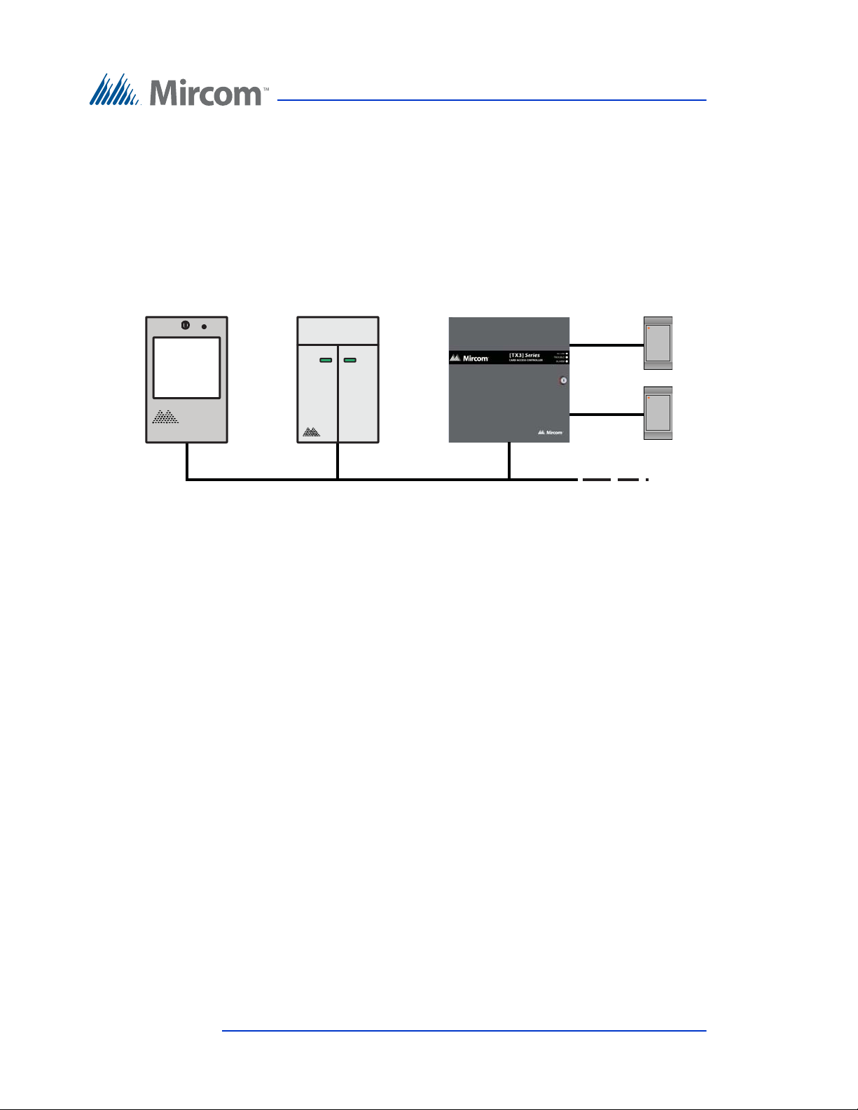
Figure 1 shows a configuration with TX3 controllers connected on an RS-485
network. Each controller has to have a unique network address on the RS-485
network. Up to 63 unique network addresses can be assigned. If you connect to
Version 4.2 TX3 Touch Screen Installation Manual 9 (126)
LT-996 Copyright 2017
Page 10
Introduction
RS-485 Network
Card Reader B
Card Reader A
Card Access ControllerTouch Screen Unit
Elevator Restriction Unit
any device on the RS-485 network (using USB, a modem, or the COM port), you
can also connect to and configure any other device on the RS-485 network using
the TX3 Configurator.
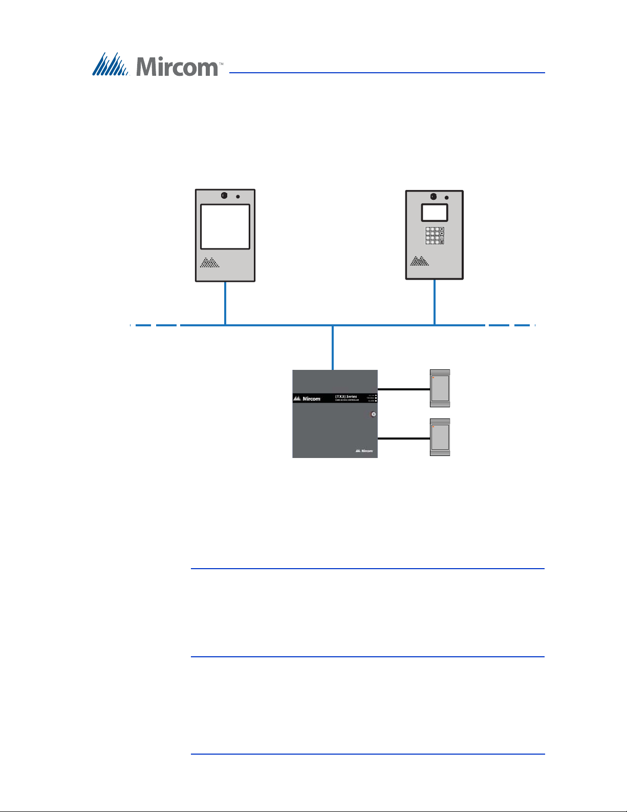
Figure 2 shows a configuration with TX3 devices connected to an Ethernet TCP/
IP network. This configuration removes the 63 device limitation that you have on
an RS-485 network. The devices connected to an Ethernet TCP/IP network are
called Master Nodes. If you connect to the TCP/IP network with the TX3
Configurator, you can connect to and configure any of the Master Nodes on the
Figure 1. TX3 devices on an RS-485 network.
10 (126) TX3 Touch Screen Installation Manual Version 4.2
LT-996 Copyright 2017
Page 11
Introduction
Card Reader B
Card Reader A
Card Access Controller
(Master Node)
Ethernet Network
Lobby Control Unit
(Master Node)
Touch Screen Unit
(Master Node)
2
ABC3DEF
1
5
JKL
6
MNO
4
GHI
8
TUV9WXYZ
7
PQRS
0
*
#
Ethernet TCP/IP network. If you connect directly to one of the Master Nodes
using USB, a modem, or a COM port, you will be able to configure that device but
not any other device.
Version 4.2 TX3 Touch Screen Installation Manual 11 (126)
LT-996 Copyright 2017
Figure 2. TX3 devices connected to an Ethernet TCP/IP network. Devices
connected to an Ethernet network are Master Nodes.
Notes: In order for a panel to be a Master Node it must satisfy the following
conditions.
• It must be IP capable. Panels that are IP capable are usually
denoted by a “-A” at the end of their model names.
• If the panel is not a Touch Screen, it must have a TX3-IP IP
Module installed.
Page 12
Introduction
RS-485 Subnetwork
Touch Screen
(Slave Node)
Card Reader B
Card Reader A
Card Access Controller
(Slave Node)
Card Reader B
Card Reader A
Card Access Controller
(Slave Node)
RS-485 Subnetwork
Ethernet Network
Lobby Control Unit
(Master Node)
2
ABC3DEF
1
5
JKL
6
MNO
4
GHI
8
TUV9WXYZ
7
PQRS
0
*
#
Lobby Control Unit
(Master Node)
2
ABC3DEF
1
5
JKL
6
MNO
4
GHI
8
TUV9WXYZ
7
PQRS
0
*
#
Elevator Restriction Unit
(Slave Node)
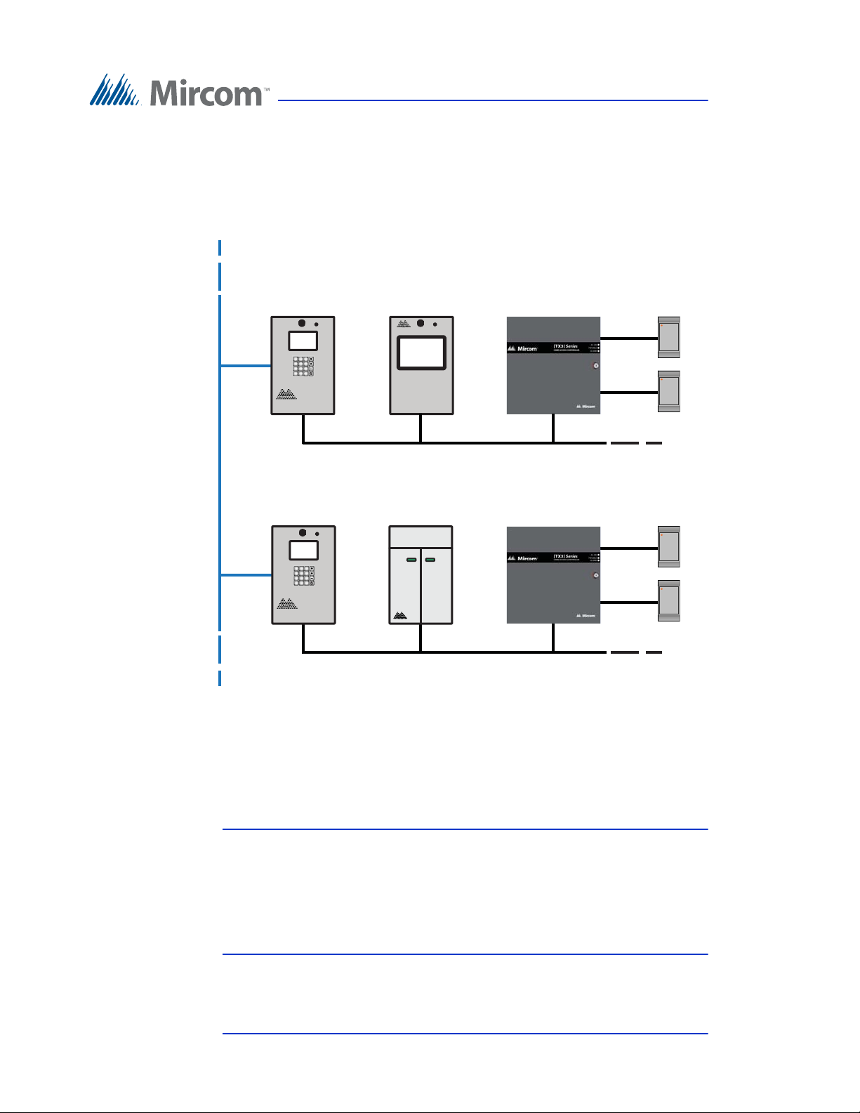
Figure 3 shows a configuration with TX3 devices connected on both an Ethernet
TCP/IP network and on RS-485 subnetworks. Devices connected to a Master
Node’s RS-485 subnetwork are Slave Nodes to the Master Node. Each RS-485
subnetwork can have up to 63 devices connected to it; you can still have more
than 63 Master Nodes connected to the Ethernet network.
Figure 3. TX3 devices connected to a combination Ethernet TCP/IP
network with RS-485 subnetworks.
If you connect to the Ethernet TCP/IP network with the TX3 Configurator, you
can configure any of the nodes in this configuration. If you connect directly to a
device using USB, a modem, or a COM port, you will only be able to configure
devices that are on the same RS-485 subnetwork as that device.
Note: Normally, there can only be one Master Node on an RS-485
subnetwork. That is, you cannot connect one RS-485 subnetwork to
another RS-485 subnetwork. However, if you want to connect to a
Touch Screen panel remotely over the Internet (for instance, to
configure Touch Screen options such as color and themes), the
12 (126) TX3 Touch Screen Installation Manual Version 4.2
LT-996 Copyright 2017
Touch Screen panel must be set as an Master Node even if there is
no slave panel connected to it.
Page 13

1.2 Features
Features of the TX3-TOUCH-S15-A and TX3-TOUCH-F15-A include:
• 15" full color industrial grade touch screen display that is viewable in
direct sunlight
• TCP/IP capability by adding optional TX3-IP module
• Constructed of heavy gauge stainless steel
• Optional built-in camera, postal lock and card access controller
• Multiple panels can be connected on a shared database for up to 63 nodes
of complete card access and facility management
• Four fully configurable themes (color & font), 4 preset themes, and 4
screen layout templates
• Configurable Welcome Screen
• Three built-in keyboard layouts (Full QWERTY, Full QWERTY + Num
pad, or Simple)
Introduction
• Standard Wiegand interface for card access
• Intuitive call interface using one call button or one-call button per resident
• Voice or video based help menu for ease of use
• Optional e-mail resident feature
• Supports both AutoDialer (ADC) and No Phone Bill (NSL)
• Elevator restriction capability
• Programming via built-in USB or Ethernet ports; available modem and
COM-to-RS485 modules for hardwired setups
• Remote Desktop capability to fully control programming and setup
• Revenue generating advertising module available
• Whisper quiet fanless operation
• 150 watt built-in premium speakers and efficient and robust Class-D
stereo amplifier
• Easily load media content via built-in USB interface. Supports JPG, GIF,
SWF, WMV and MPEG file formats
• Fully removable lightweight inner chassis for easy maintenance
• Industry Canada and F.C.C. approved
Features of the TX3-TOUCH-S15-B and TX3-TOUCH-F15-B include:
• 2000 name capacity
• TCP/IP capability to remotely program and maintain the system
Version 4.2 TX3 Touch Screen Installation Manual 13 (126)
LT-996 Copyright 2017
Page 14

Introduction
• Built-in HD web camera for video communication to the suite
• Optional system diagnostic software for remote monitoring
• Multi-language support; English and French are provided and a language
editor allows all text to be translated into other languages
• Integrated advertising module offsets capital costs and generates recurring
revenue for the property
• Configurable themes, screens and layouts allow customization to any
decor
• Built-in Wiegand proximity reader, 125 KHz
• Optional high definition AXIS IP Camera
• Provision for postal lock
• Provision for single door controller (TX3-CX-1NP)
• Integrates with TX3 InSuite device
Features of TX3-TOUCH-S22 and TX3-TOUCH-F22 include:
• 2000 name capacity
• TCP/IP capability to remotely program and maintain the system
• Built-in HD web camera for video communication to the suite
• Optional system diagnostic software for remote monitoring
• Multi-language support; English and French are provided and a language
editor allows all text to be translated into other languages
• Integrated advertising module offsets capital costs and generates recurring
revenue for the property
• Configurable themes, screens and layouts allow customization to any
decor
• Built-in Wiegand proximity reader, 125 KHz
• Optional high definition AXIS IP Camera
• Provision for postal lock
• Provision for two door controller (TX3-CX-2)
• Provision for single door controller (TX3-CX-1NP)
• Integrates with TX3 InSuite device
1.3 Touch Screen Sizes and Enclosures
There are three types of enclosures for the 15 inch Touch Screen: kiosk, surface
mount, and flush mount.
14 (126) TX3 Touch Screen Installation Manual Version 4.2
LT-996 Copyright 2017
Page 15

1.3.1 15 Inch Models
The 15 inch Touch Screen models are stand alone, surface or flush mounted.
TX3-TOUCH-K15-A. 15” Touch Screen kiosk, stainless steel finish Touch
Screen with speaker, microswitch for postal lock, and external MD-990 power
supply. Designed for indoor use. The TX3-TOUCH-K15-A can be configured as
a Master Node on an Ethernet network.
TX3-TOUCH-F15-A. 15” Touch Screen flush mount, stainless steel finish
Touch Screen with speaker, microswitch for postal lock, external MD-990 power
supply, and flush mounting back box. Designed for indoor use. Can be
configured as a Master Node on an Ethernet network.
TX3-TOUCH-S15-A. 15” Touch Screen surface mount, stainless steel finish
Touch Screen with speaker, microswitch for postal lock, external MD-990 power
supply, and surface mounting back box. Designed for indoor use. Can be
configured as a Master Node on an Ethernet network.
TX3-TOUCH-F15-B. 15” Touch Screen flush mount, stainless steel finish
Touch Screen with speaker, microswitch for postal lock, external MD-990 power
supply, and flush mounting back box. Designed for indoor use. Can be
configured as a Master Node on an Ethernet network.
Introduction
TX3-TOUCH-S15-B. 15” Touch Screen surface mount, stainless steel finish
Touch Screen with speaker, microswitch for postal lock, external MD-990 power
supply, and surface mounting back box. Designed for indoor use. Can be
configured as a Master Node on an Ethernet network.
1.3.2 22 Inch Models
The 22 inch Touch Screen models are surface or flush mounted.
TX3-TOUCH-S22. 22” Touch Screen surface mount, stainless steel finish
Touch Screen with speaker, microswitch for postal lock, external MD-990 power
supply, and surface mounting back box. Designed for indoor use. The TX3TOUCH-S22 can be configured as a Master Node on an Ethernet network.
TX3-TOUCH-F22. 22” Touch Screen flush mount, stainless steel finish Touch
Screen with speaker, microswitch for postal lock, external MD-990 power
supply, and lush mounting back box. Designed for indoor use. The TX3TOUCH-F22 can be configured as a Master Node on an Ethernet network.
1.4 Touch Screen Accessories
The Touch Screen accessories consist of the following items:
• TX3-T-KIOSK: Black free standing mount for TOUCH Series
Version 4.2 TX3 Touch Screen Installation Manual 15 (126)
LT-996 Copyright 2017
Page 16

• TX3-T-KIOSK2: Black free standing square pillar mount for TX3TOUCH-S15-B and TX3-TOUCH-S22
• TX3-T-KIOSK3: Black enclosed pillar mount for TX3-TOUCH-S22
• P1264 IP camera
• TX3-GPM Guard Phone Module
•Postal Lock
• TX3-USB-AD Kit
• TX3-CX-1NP Single Door Control Module, PoE, 12 VDC, 24-48 VDC
1.5 Mounting requirements from the 2010 ADA Standards for Accessible Design
See http://www.ada.gov/ for more information.
308.2 Forward Reach.
Introduction
308.2.1 Unobstructed. Where a forward reach is unobstructed, the high forward
reach shall be 48 inches (1220 mm) maximum and the low forward reach shall be
15 inches (380 mm) minimum above the finish floor or ground.
308.2.2 Obstructed High Reach. Where a high forward reach is over an
obstruction, the clear floor space shall extend beneath the element for a distance
not less than the required reach depth over the obstruction. The high forward
reach shall be 48 inches (1220 mm) maximum where the reach depth is 20 inches
(510 mm) maximum. Where the reach depth exceeds 20 inches (510 mm), the
high forward reach shall be 44 inches (1120 mm) maximum and the reach depth
shall be 25 inches (635 mm) maximum.
308.3 Side Reach.
308.3.1 Unobstructed. Where a clear floor or ground space allows a parallel
approach to an element and the side reach is unobstructed, the high side reach
shall be 48 inches (1220 mm) maximum and the low side reach shall be 15 inches
(380 mm) minimum above the finish floor or ground.
EXCEPTIONS:
1. An obstruction shall be permitted between the clear floor or ground space and
the element where the depth of the obstruction is 10 inches (255 mm) maximum.
2. Operable parts of fuel dispensers shall be permitted to be 54 inches (1370 mm)
maximum measured from the surface of the vehicular way where fuel dispensers
are installed on existing curbs.
16 (126) TX3 Touch Screen Installation Manual Version 4.2
LT-996 Copyright 2017
Page 17

308.3.2 Obstructed High Reach. Where a clear floor or ground space allows a
parallel approach to an element and the high side reach is over an obstruction, the
height of the obstruction shall be 34 inches (865 mm) maximum and the depth of
the obstruction shall be 24 inches (610 mm) maximum. The high side reach shall
be 48 inches (1220 mm) maximum for a reach depth of 10 inches (255 mm)
maximum. Where the reach depth exceeds 10 inches (255 mm), the high side
reach shall be 46 inches (1170 mm) maximum for a reach depth of 24 inches (610
mm) maximum.
EXCEPTIONS:
1. The top of washing machines and clothes dryers shall be permitted to be 36
inches (915 mm) maximum above the finish floor.
2. Operable parts of fuel dispensers shall be permitted to be 54 inches (1370 mm)
maximum measured from the surface of the vehicular way where fuel dispensers
are installed on existing curbs.
1.6 Warranty and Special Notices
Introduction
Mircom values your business and always attempts to provide you with the very
best service.
Please see the Warranty and Special Notices chapter on page 120 for information
about the warranty and special notices about equipment use.
1.7 About This Manual
This manual provides comprehensive information on the installation and
configuration of the TX3 Series Touch Screen by the installation technician.
Tasks are described in the order that they are likely to be performed.
This manual applies to the following models:
• TX3-TOUCH-K15-A
• TX3-TOUCH-F15-A
• TX3-TOUCH-S15-A
• TX3-TOUCH-F15-B
• TX3-TOUCH-S15-B
•TX3-TOUCH-S22
•TX3-TOUCH-F22
• TX3-T-KIOSK
• TX3-T-KIOSK2
• TX3-T-KIOSK3
Version 4.2 TX3 Touch Screen Installation Manual 17 (126)
LT-996 Copyright 2017
Page 18

1.7.1 Version Control
The version number appears on the front cover and changes whenever there is a
major or minor update to any part of the system regarding operation or
configuration.
The following convention indicates major or minor changes:
Initial release. Version 1.00.0
Major change. Version 2.00.0
Minor change. Version 2.01.0
Pre-release changes. Version 2.01.1
1.7.2 Additional Documentation
For additional documentation, see the following Mircom literature:
Introduction
• TX3 Configuration and Administrator Manual LT-995
• TX3-Telephone Access System Installation and Operation Manual LT969
• TX3-CX Card Access System Installation and Operation Manual LT-980
• TX3-CX-A8 Aperio Interface Panel Installation and Operation Manual
LT-1160
• TX3-CX-1NP Installation Manual LT-5997
• TX3 Two Door Card Access System Kit Catalogue Number 6531
• TX3 Series Elevator Restriction Accessories Catalogue Number 6532
1.8 Contact Us
Mircom fosters a collaborative support process and environment in providing
early feedback to meet your specific needs.
18 (126) TX3 Touch Screen Installation Manual Version 4.2
LT-996 Copyright 2017
Page 19

You can contact us from Monday to Friday 8:00 A.M. to 5:00 P.M. E.S.T.
1.8.1 General Inquiries
For general inquiries call us at the following numbers:
Toll Free: 1-888-660-4655
Local: 905-660-4655
1.8.2 Customer Service
Customer service is available at the following numbers:
Toll Free: 1-888-MIRCOM5
Local: 905-695-3535
Local Fax: 905-660-4113
Introduction
Toll-Free Fax: 1-888-660-4113
1.8.3 Website
Visit the Mircom website, at www.mircom.com, to find the product information
you are looking for and to learn about troubleshooting, training and technical
support options.
The website provides avenues for customers to ask questions about new and
existing technologies, and receive expert technical support about software and
products. Visit www.mircom.com/chat.
1.8.4 Email
As a customer you quickly become informed on how we can help with new
products and technologies. Contact Mircom at [email protected].
1.8.5 Technical Support
For technical support contact Mircom’s Technical Support Department between
8 A.M. and 5 P.M. (EST) Monday through Friday, excluding holidays.
Toll Free: 1-888-MIRCOM5
Local: 905-695-3535
Local Phone: 905-660-4655
Toll Free Phone: 1-888-660-4655
Email: [email protected]
Version 4.2 TX3 Touch Screen Installation Manual 19 (126)
LT-996 Copyright 2017
Page 20

2 Enclosure Installation
This chapter provides information on how to install the various enclosures and
pre-assembled components.
This chapter explains
• Installing TX3-TOUCH-S15-A - page 22
• Installing TX3-TOUCH-F15-A- page 25
• Installing TX3-TOUCH-F15-B - page 28
• Installing TX3-TOUCH-S15-B - page 30
• Installing TX3-TOUCH-S22 and TX3-TOUCH-F22 - page 32
• Installing TX3-T-KIOSK2 - page 43
• Installing TX3-T-KIOSK3 - page 51
• Installing TX3-TOUCH-K15-A - page 58
• Installing TX3-TOUCH-K15-A - page 58
• Installing the Power Supply Enclosure - page 63
20 (126) TX3 Touch Screen Installation Manual Version 4.2
LT-996 Copyright 2017
Page 21

Enclosure Installation
2.1 Installing the Enclosures and Touch Screen
The Touch Screen Kiosk, Surface Mount and Flush Mounts units consist of the
following pre-assembled components:
Kiosk. The kiosk is a pedestal mounted Touch Screen TX3-TOUCH-K15-A unit
and consists of the following components:
• Touch Screen Base Plate
• Touch Screen Kiosk
• Touch Screen Panel
• Touch Screen Speakers
• Touch Screen Frame
• Touch Screen Door
Surface Mount. The surface mount unit is a TX3-TOUCH-S15-A or TX3TOUCH-S22 unit and consists of the following components:
• Touch Screen Enclosure
• Touch Screen Panel
• Touch Screen Speakers
• Touch Screen Frame
• Touch Screen Door
Flush Mount. The surface mount unit is a TX3-TOUCH-F15-A or TX3-
TOUCH-F22 unit and consists of the following components:
• Touch Screen Enclosure
• Touch Screen Panel
• Touch Screen Speakers
• Touch Screen Frame
• Touch Screen Door
Version 4.2 TX3 Touch Screen Installation Manual 21 (126)
LT-996 Copyright 2017
Page 22
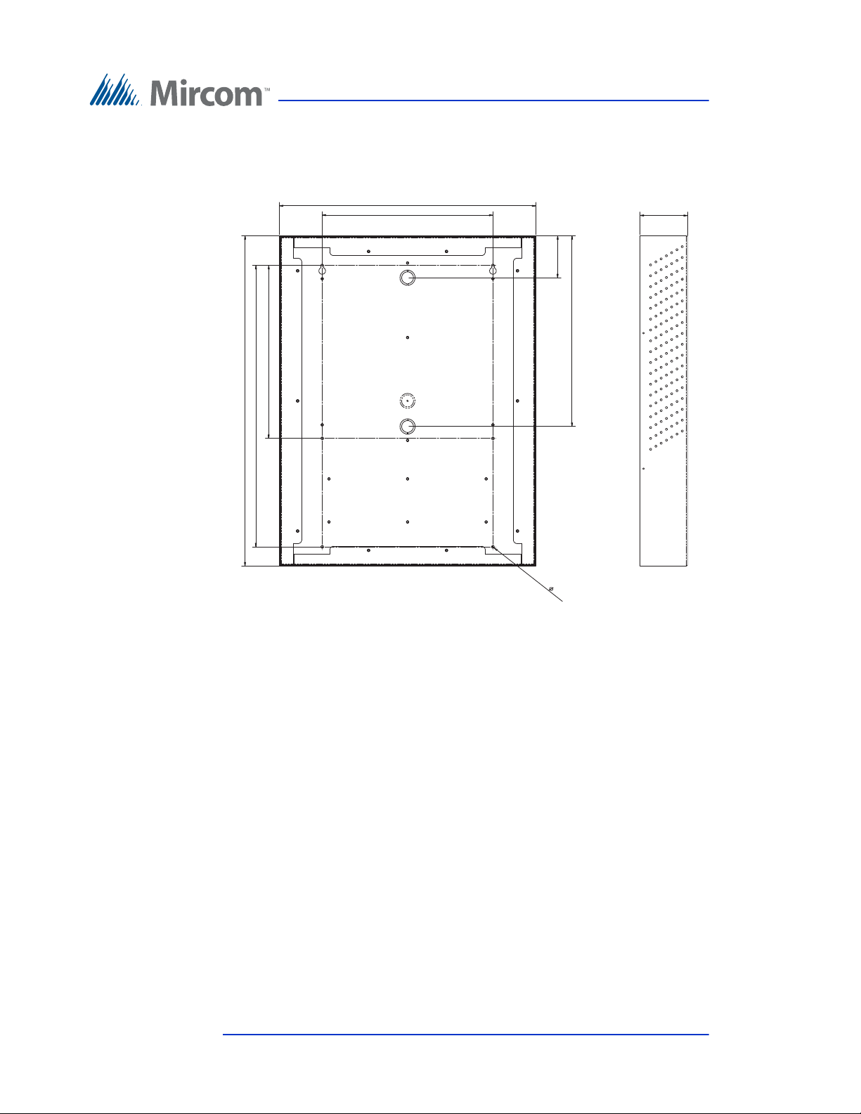
2.2 Installing TX3-TOUCH-S15-A
24.360 24.360
12.759 12.759
20.759 20.759
18.920 18.920
12.600 12.600
3.093 3.093
14.068 14.068
0.213 0.
213
3.500 3.500
Enclosure Installation
Figure 4. TX3-TOUCH-S15-A Surface Mount Back Dimensions
(inches)
22 (126) TX3 Touch Screen Installation Manual Version 4.2
LT-996 Copyright 2017
Page 23
Enclosure Installation
26.200
19.000
3.622
0.120
26.200
19.000
0.120
3.622
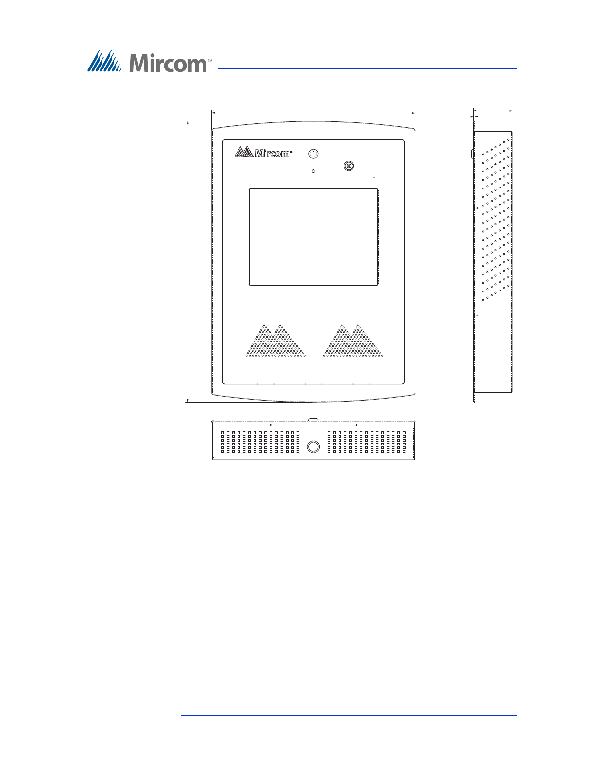
Figure 5. TX3-TOUCH-S15-A Surface Mount Front Dimensions
(inches)
The surface mount enclosure mounts on the wall. Mount the enclosure right-side
up (the Mircom logo on the door is on the bottom).
You need:
• 6 fasteners appropriate for the wall that you are mounting the enclosure
on.
Version 4.2 TX3 Touch Screen Installation Manual 23 (126)
LT-996 Copyright 2017
Page 24
Enclosure Installation
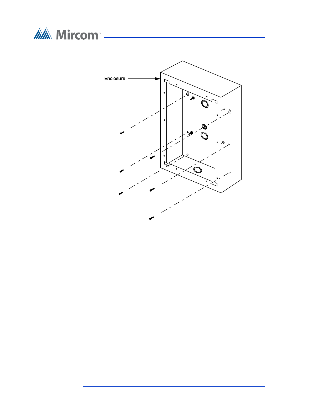
Figure 6. Touch Screen Surface Mount
To install the surface mount enclosure
1. Find a suitable location for the enclosure.
2. Using the enclosure as a template, mark the back mounting locations of the
two keyholes as shown in Figure 6. Ensure that at least one side is over a
wall stud.
3. Remove the enclosure and place the fasteners halfway into the wall into
the marked hole locations.
4. Place the enclosure onto the fasteners and lower it so that the fasteners fit
in the narrow part of the keyholes.
5. Screw the other four fasteners into the four remaining holes.
6. Tighten all fasteners into place.
7. Proceed with the power supply installation described in section 2.11 on
page 63.
24 (126) TX3 Touch Screen Installation Manual Version 4.2
LT-996 Copyright 2017
Page 25

2.3 Installing TX3-TOUCH-F15-A
12.600 12.600
18.000 18.000
12.750 12.750
20.750 20.750
2.825 2.825
13.800 13.800
0.213 0.213
23.825 23.825
3.500 3.500
2.500 2.500
21.225 21.225
0.218 0.218
1.400 1.400
1.200 1.200
Enclosure Installation
Figure 7. TX3-TOUCH-F15-A Flush Mount Back Dimensions
(inches)
Version 4.2 TX3 Touch Screen Installation Manual 25 (126)
LT-996 Copyright 2017
Page 26
Enclosure Installation
26.200
19.000
3.622
0.120
2.500
21.225
1.400
26.200
19.000
0.120
3.622
1.400
2.500
21.225
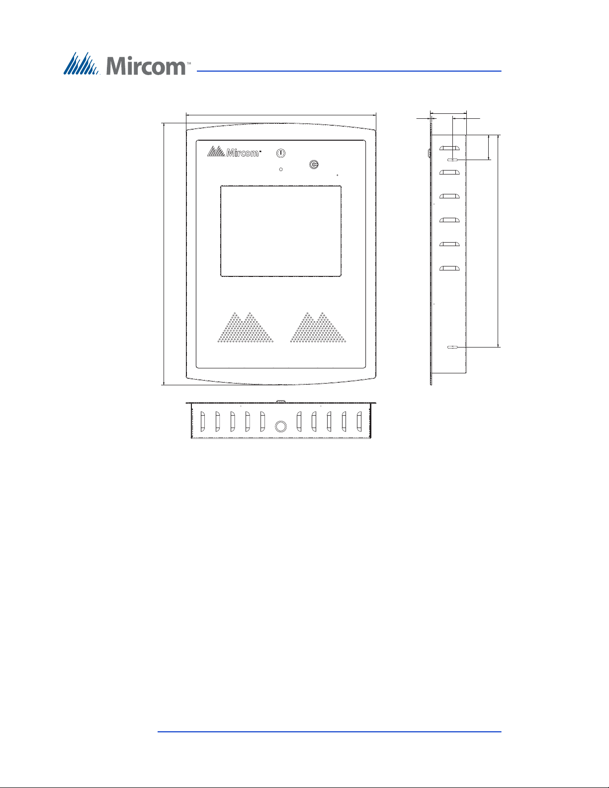
Figure 8. TX3-TOUCH-F15-A Flush Mount Front Dimensions
(inches)
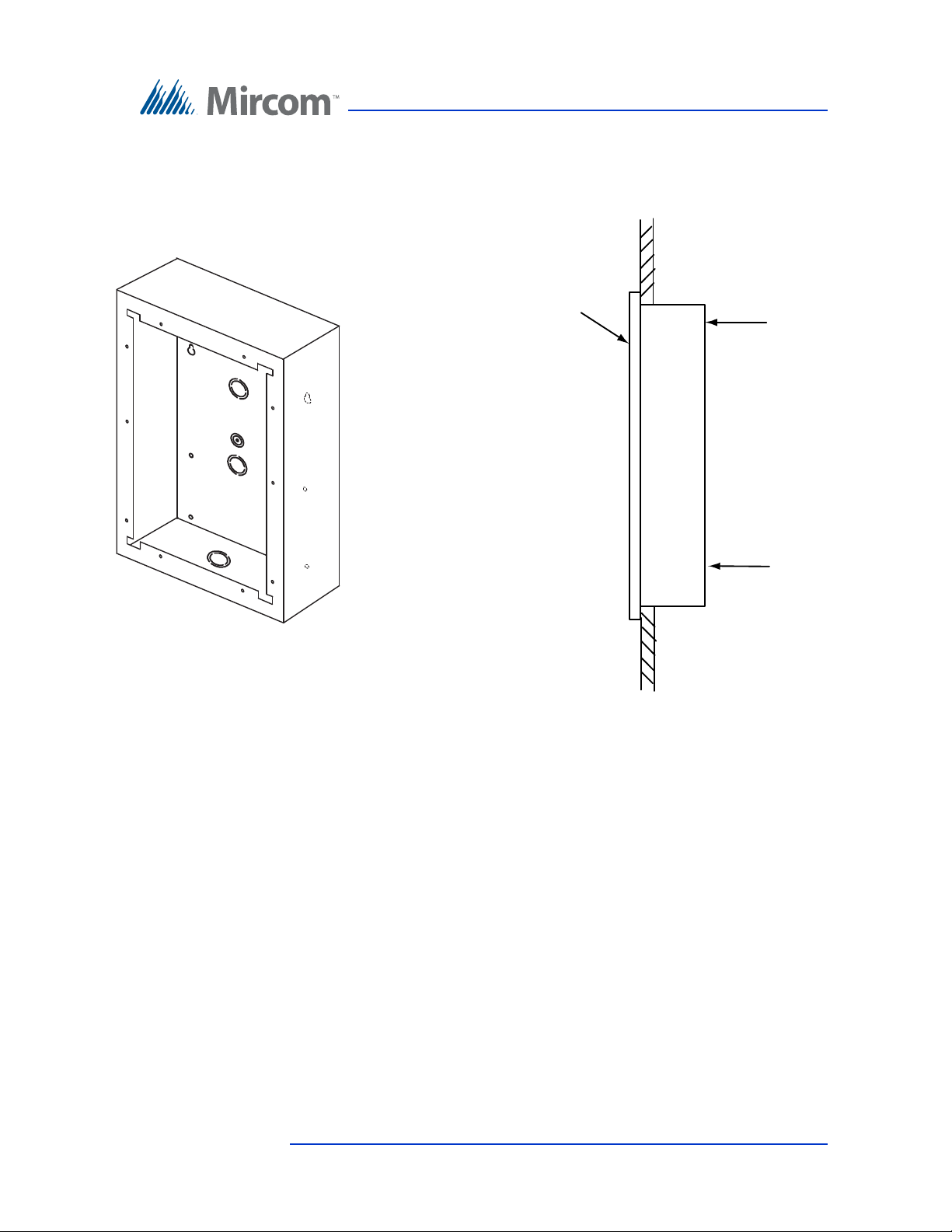
The flush mount enclosure mounts directly inside the wall to the wall stud or
supporting structure as shown in Figure 9. Mount the enclosure flush with the
wall and right-side up (the knock out is at the bottom).
You need:
• 6 fasteners appropriate for the wall that you are mounting the enclosure on.
26 (126) TX3 Touch Screen Installation Manual Version 4.2
LT-996 Copyright 2017
Page 27
Enclosure Installation
Wall
Front
Frame
Side View
Enclosure
To p
GROUND
SCREW
LOCATION
Enclosure
Figure 9. Flush Mount Enclosure
To install the flush mount enclosure
1. Find a suitable location for the enclosure. You can mount the enclosure
using the keyholes on the back, or the knockouts on the side, or both.
2. Using the enclosure as a template, trace an opening in the wall for the
cutout with one side aligned with the side of the wall stud.
3. Cut an opening in the wall 0.1 inch larger than the trace ensuring that one
side is aligned with the wall stud or supporting structure.
4. Insert the enclosure into the wall cutout and using the side of the enclosure
as a template mark the hole mounting locations (either keyholes or
knockouts or both).
Version 4.2 TX3 Touch Screen Installation Manual 27 (126)
LT-996 Copyright 2017
Page 28

5. If you are using the keyholes, remove the enclosure and place 2 fasteners
halfway into the wall into the marked keyhole locations. Then place the
enclosure onto the top fasteners and lower it so that the fasteners fit in the
narrow part of the keyholes.
6. Screw the other fasteners into the remaining holes or knockouts.
7. Tighten all fasteners into place.
8. Proceed with the power supply installation described in section 2.11 on
page 63.
2.4 Installing TX3-TOUCH-F15-B
The flush mount enclosure mounts on the wall. Mount the enclosure right-side up
(the Mircom logo on the door is on the bottom).
You need:
• 4 fasteners appropriate for the wall that you are mounting the enclosure on.
Enclosure Installation
To flush mount the enclosure
1. Find a suitable location for the enclosure. You can mount the enclosure
using the keyholes on the back, or the knockouts on the side, or both.
2. Trace an opening in the wall for the enclosure with one side aligned with a
wall stud.
3. Cut an opening in the wall 3/32” (3 mm) larger than the tracing, ensuring
that one side is aligned with the wall stud or supporting structure.
4. Insert the enclosure into the wall cutout, and using the side of the enclosure
as a template mark the hole mounting locations (either keyholes or
knockouts or both).
5. If you are using the keyholes, remove the enclosure and place 2 fasteners
halfway into the wall into the two top keyhole locations.
6. Place the enclosure onto the top fasteners, then lower it so that the fasteners
fit in the narrow part of the keyholes.
7. Screw the other fasteners into the remaining holes.
8. Tighten all fasteners into place.
9. Proceed with the power supply installation described in section 2.11 on
page 63.
28 (126) TX3 Touch Screen Installation Manual Version 4.2
LT-996 Copyright 2017
Page 29
Enclosure Installation
22”
(559 mm)
17 1/2”
(445 mm)
3 51/64”
(96 mm)
3 31/32”
(101 mm)
1 1/4”
(32 mm)
16 19⁄64”
(414 mm)
20 3/4”
(527 mm)
2 7/32”
(57 mm)
4 1/2”
(114 mm)
17 9⁄16”
(446 mm)
12 3/4”
(324 mm)
12 19⁄32”
(320 mm)
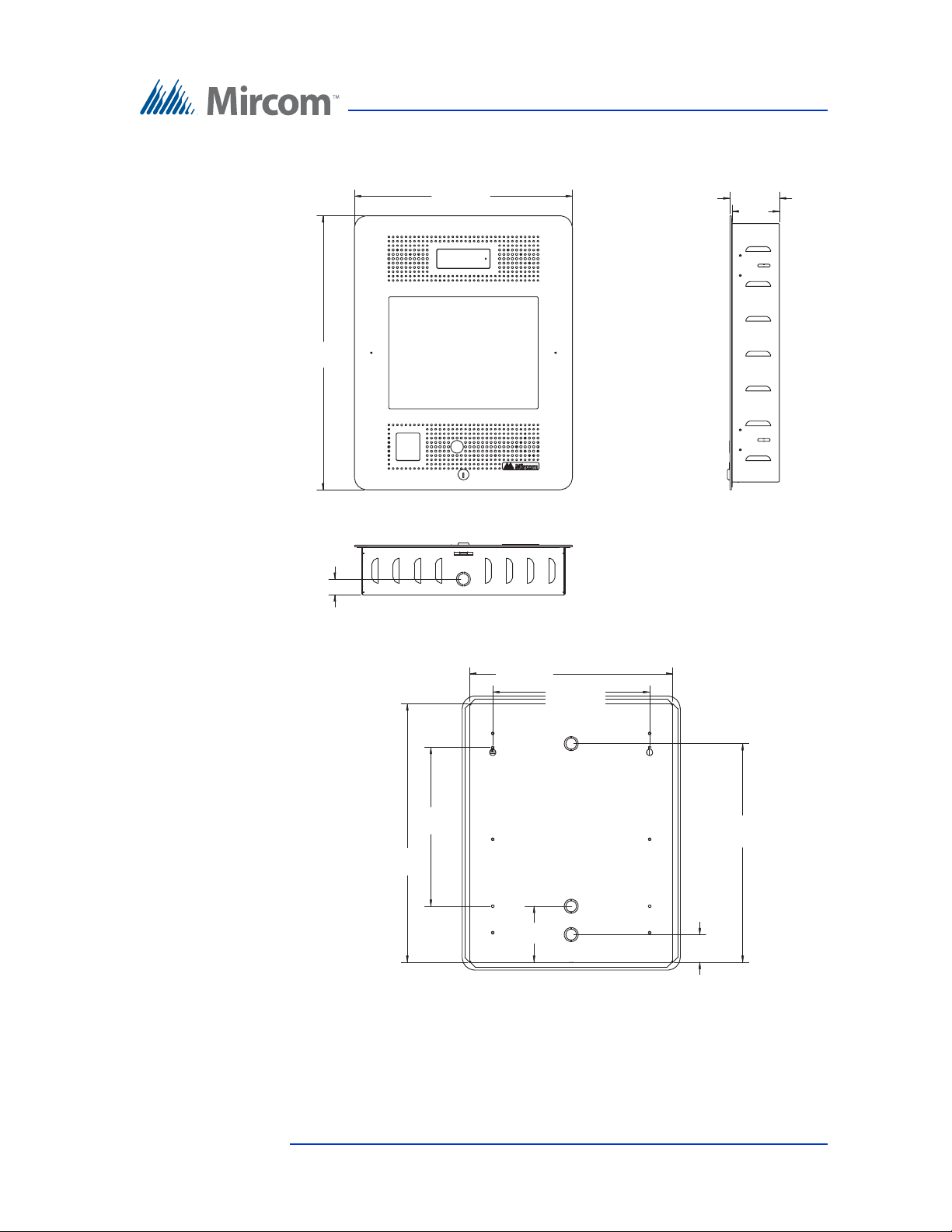
Figure 10. TX-TOUCH-F15-B Dimensions
Figure 11. TX-TOUCH-F15-B Dimensions
Version 4.2 TX3 Touch Screen Installation Manual 29 (126)
LT-996 Copyright 2017
Page 30

2.5 Installing TX3-TOUCH-S15-B
The surface mount enclosure mounts on the wall. Mount the enclosure right-side
up (the Mircom logo on the door is on the bottom).
You need:
• 4 fasteners appropriate for the wall that you are mounting the enclosure on.
To surface mount the enclosure
1. Find a suitable location for the enclosure.
2. Mark the back mounting locations of the two top screws. Ensure that at
least one screw is over a wall stud.
3. Place the fasteners halfway into the wall in the two top keyhole locations
and wall stud.
4. Place the enclosure onto the fasteners, then lower it so that the fasteners fit
in the narrow part of the keyholes.
Enclosure Installation
5. Screw the other fasteners into the remaining holes.
6. Tighten all fasteners into place.
7. Proceed with the power supply installation described in section 2.11 on
page 63.
30 (126) TX3 Touch Screen Installation Manual Version 4.2
LT-996 Copyright 2017
Page 31
Enclosure Installation
23 51/64”
(604 mm)
3 31/32”
(101 mm)
70.00°
17 1/2”
(445 mm)
(
16 19⁄64”
(414 mm)
12 19⁄32”
(320 mm)
12 3/4”
(324 mm)
20 3/4”
(527 mm)
17 9⁄16”
(446 mm)
2 7/32”
(57 mm)
4 1/2”
(114 mm)
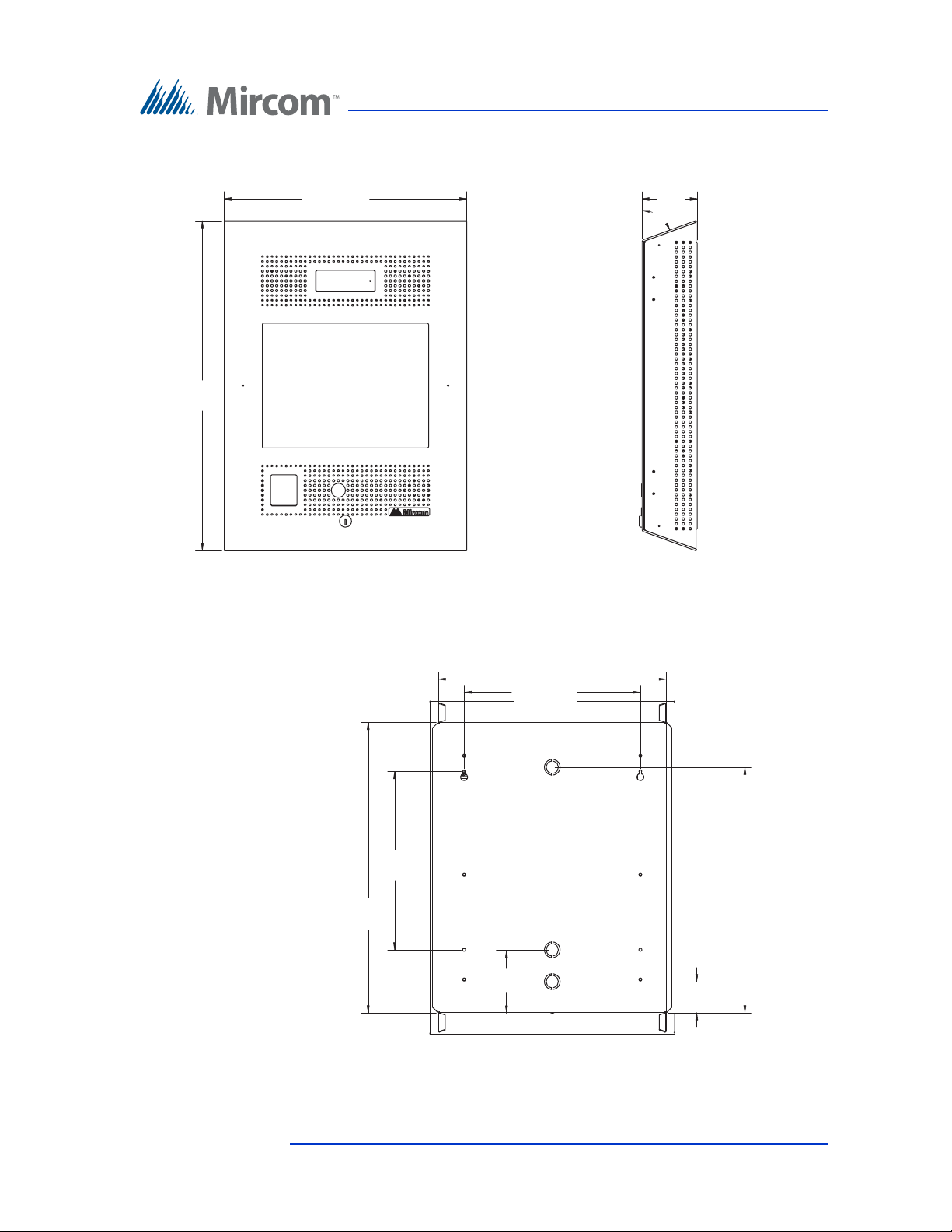
Figure 12. TX-TOUCH-S15-B Dimensions
Figure 13. TX-TOUCH-S15-B Dimensions
Version 4.2 TX3 Touch Screen Installation Manual 31 (126)
LT-996 Copyright 2017
Page 32
Enclosure Installation
Keyhole Keyhole
screw
screw
screw
screw
2.6 Installing TX3-TOUCH-S22 and TX3-TOUCH-F22
Attention: The 22” Touch Screen enclosures are heavy (80 lbs or 37 kg). Never
attempt to lift this product by yourself. At least two people should
lift it together.
2.6.1 Installing TX3-TOUCH-S22
The surface mount enclosure mounts on the wall. Mount the enclosure right-side
up (the Mircom logo on the door is on the bottom).
You need:
6 fasteners appropriate for the wall that you are mounting the enclosure on.
To mount the enclosure
1. Find a suitable location for the surface mount enclosure over a wall stud.
The wall must be able to support a weight of 80 lbs (37 kg).
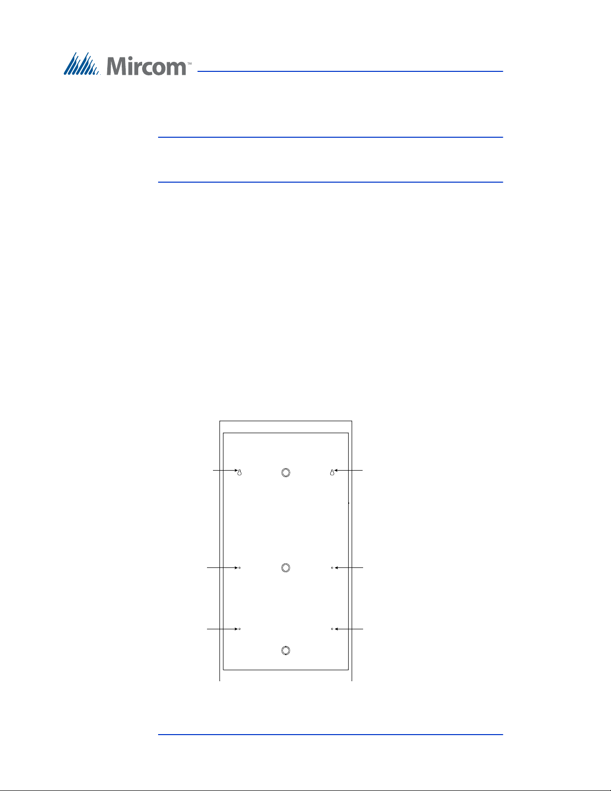
2. Using the surface mount enclosure as a template, mark the back mounting
hole locations of the two keyholes as shown in Figure 14.. Ensure that at
least one side is over a wall stud.
Figure 14. Surface mounting the enclosure
32 (126) TX3 Touch Screen Installation Manual Version 4.2
LT-996 Copyright 2017
Page 33

3. Remove the enclosure and place the top two fasteners halfway into the
marked hole locations and wall stud.
4. Place the enclosure onto the two fasteners and lower it so that the fasteners
fit in the narrow part of the keyholes.
5. Screw the other four fasteners into the four remaining holes.
6. Tighten all six fasteners into place.
7. Close the door until it clips into place.
8. Proceed with the power supply installation described in section 2.11 on
page 63.
2.6.2 Installing TX3-TOUCH-F22
The flush mount enclosure mounts directly inside the wall to the wall stud or
supporting structure. Mount the enclosure flush with the wall and right-side up
(the Mircom logo on the door is on the bottom).
Enclosure Installation
You need:
6 fasteners appropriate for the wall that you are mounting the enclosure on.
To mount the enclosure
1. Find a suitable location for the flush mount enclosure beside a wall stud.
You can mount the enclosure using the keyholes on the back, or the
knockouts on the side, or both. The wall must be able to support a weight of
80 lbs (37 kg).
2. Using the enclosure as a template, trace an opening in the wall for the cut
out with one side aligned with the side of the wall stud.
3. Cut an opening in the wall 0.1 inch larger than the trace ensuring that one
side is aligned with the wall stud or supporting structure.
4. Insert the enclosure into the wall cutout and using the side of the enclosure
as a template mark the hole mounting locations (either keyholes or
knockouts or both).
Version 4.2 TX3 Touch Screen Installation Manual 33 (126)
LT-996 Copyright 2017
Page 34
Enclosure Installation
Keyhole
Keyhole
screw
screw
screw
screw
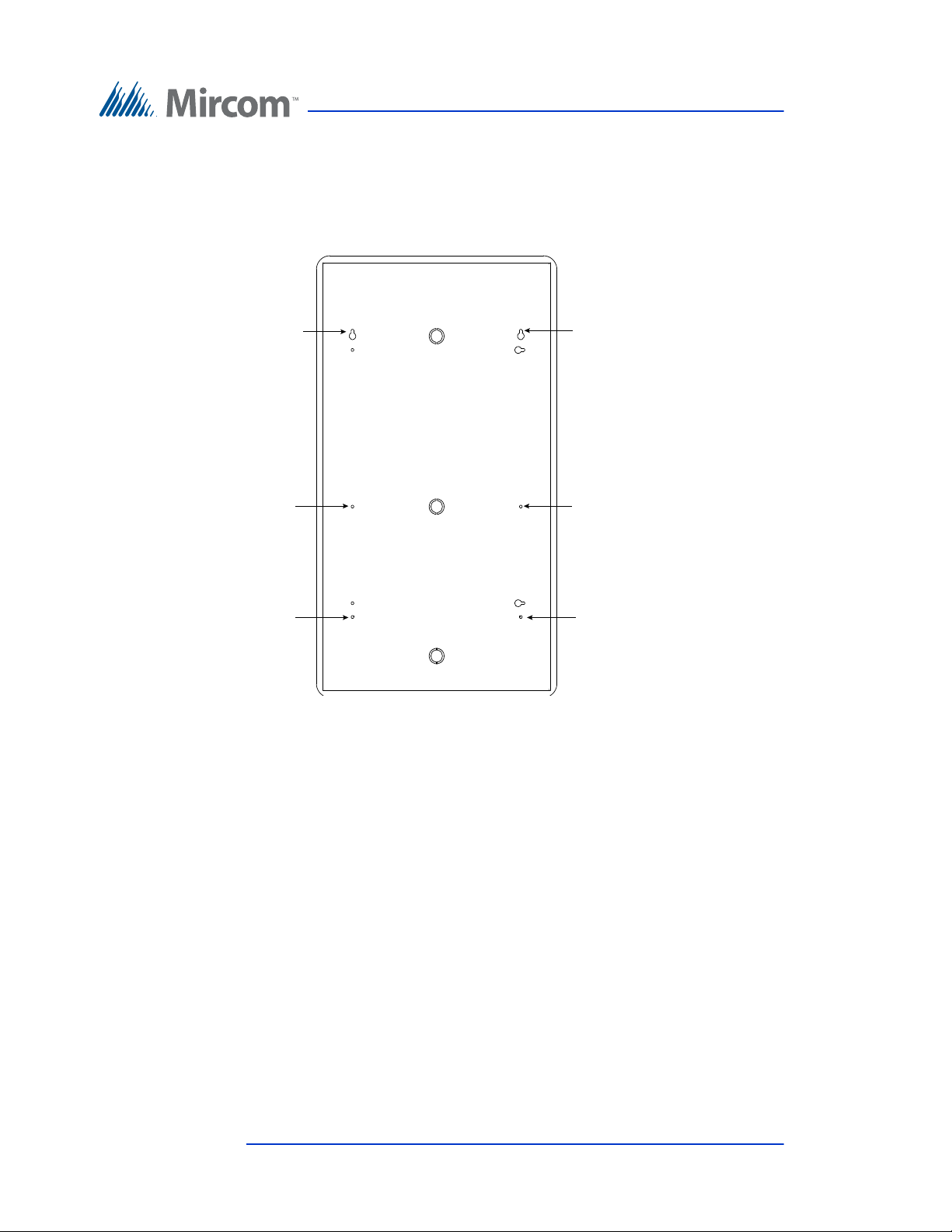
5. If you are using the keyholes, remove the enclosure and place 2 fasteners
halfway into the wall into the marked keyhole locations. Then place the
enclosure onto the top fasteners and lower it so that the fasteners fit in the
narrow part of the keyholes. as shown in Figure 15. Ensure that at least one
side is beside a wall stud.
Figure 15. Flush mounting the enclosure
6. Screw the other four fasteners into the four remaining holes or knockouts.
7. Tighten all fasteners into place.
8. Close the door until it clips into place.
9. Proceed with the power supply installation described in section 2.11 on
page 63.
34 (126) TX3 Touch Screen Installation Manual Version 4.2
LT-996 Copyright 2017
Page 35
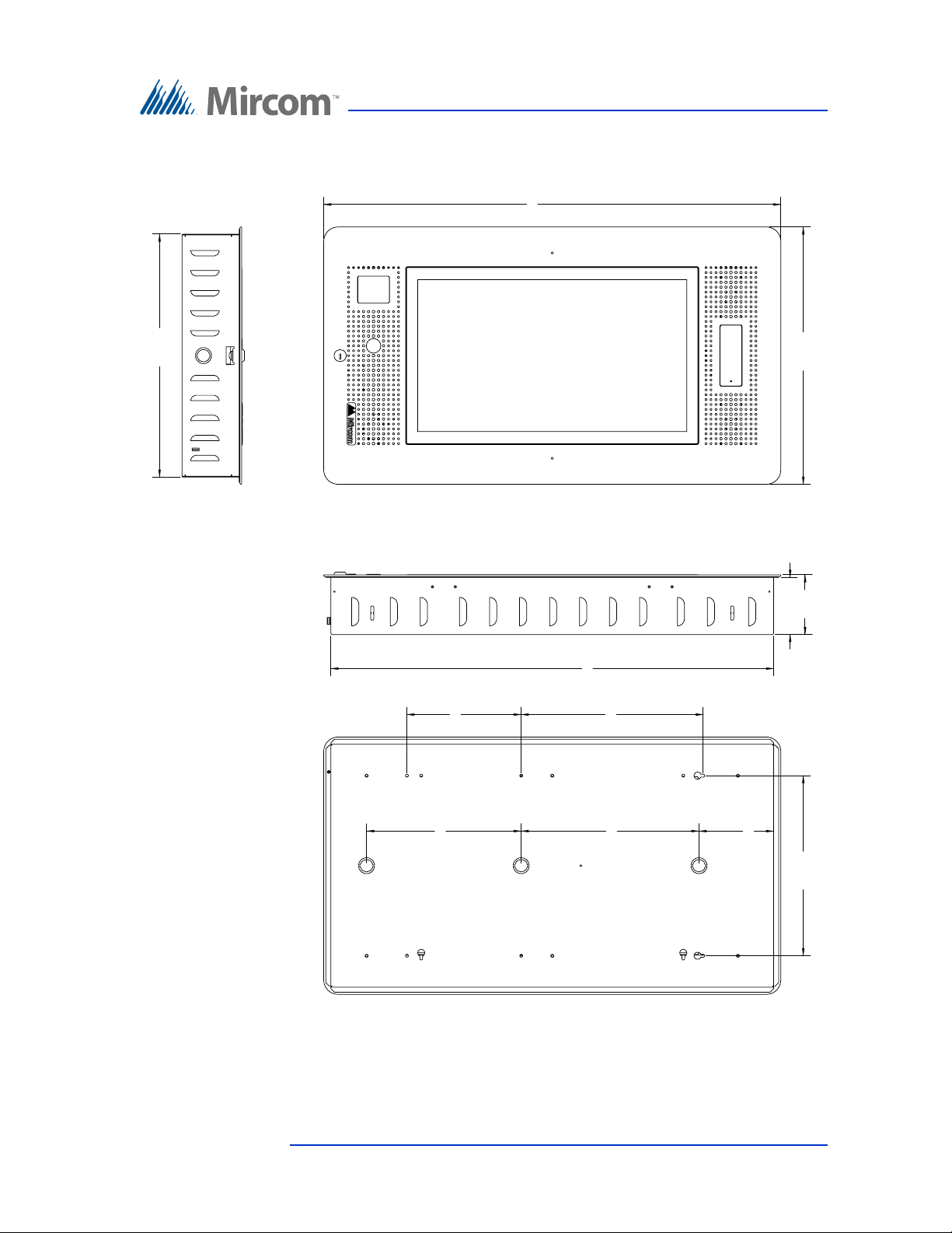
32.000
18.000
4.000
4.177
31.000
12.600
12.750
8.000
12.450
10.825
5.225
17.000
Enclosure Installation
Figure 16. TX3-TOUCH-F22 Dimensions (inches)
Version 4.2 TX3 Touch Screen Installation Manual 35 (126)
LT-996 Copyright 2017
Page 36
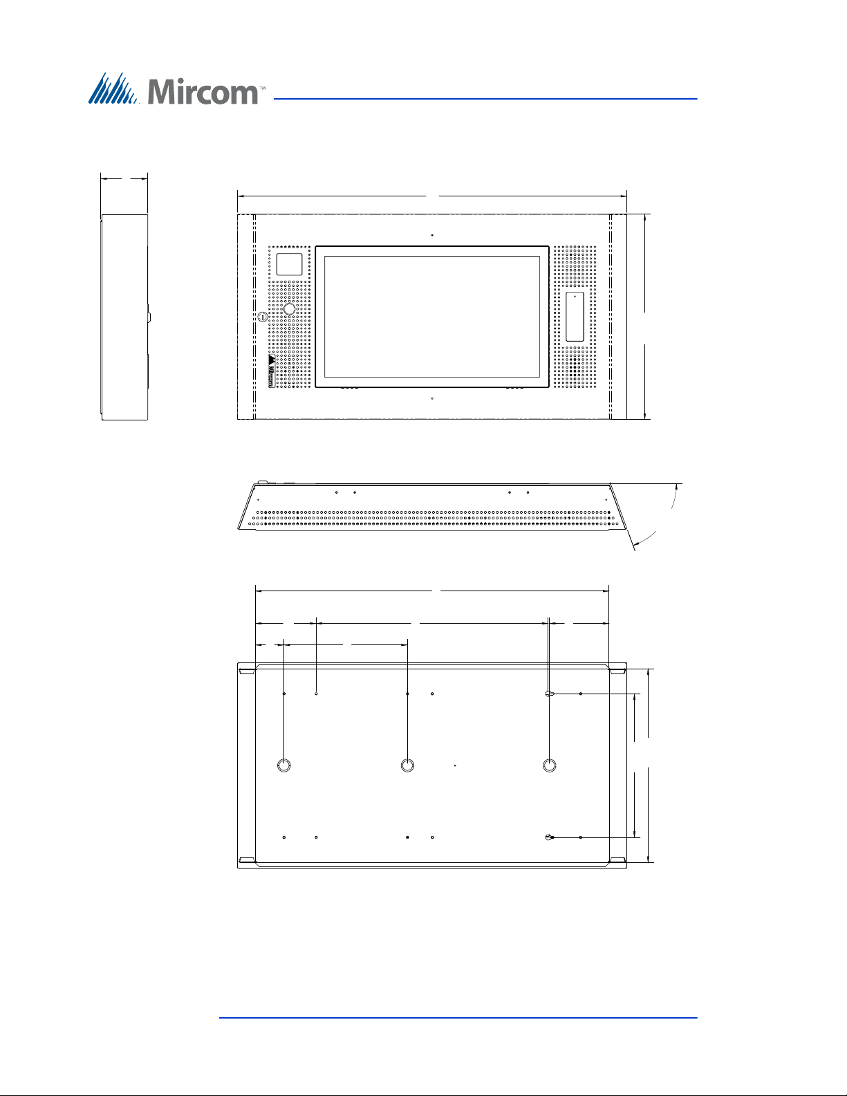
34.118
18.000
70.00°
(X2)
17.000
31.000
12.600
20.350
2.500
5.325
10.825
5.225
4.125
Enclosure Installation
Figure 17. TX3-TOUCH-S22 Dimensions (inches)
36 (126) TX3 Touch Screen Installation Manual Version 4.2
LT-996 Copyright 2017
Page 37
2.7 Installing TX3-T-KIOSK
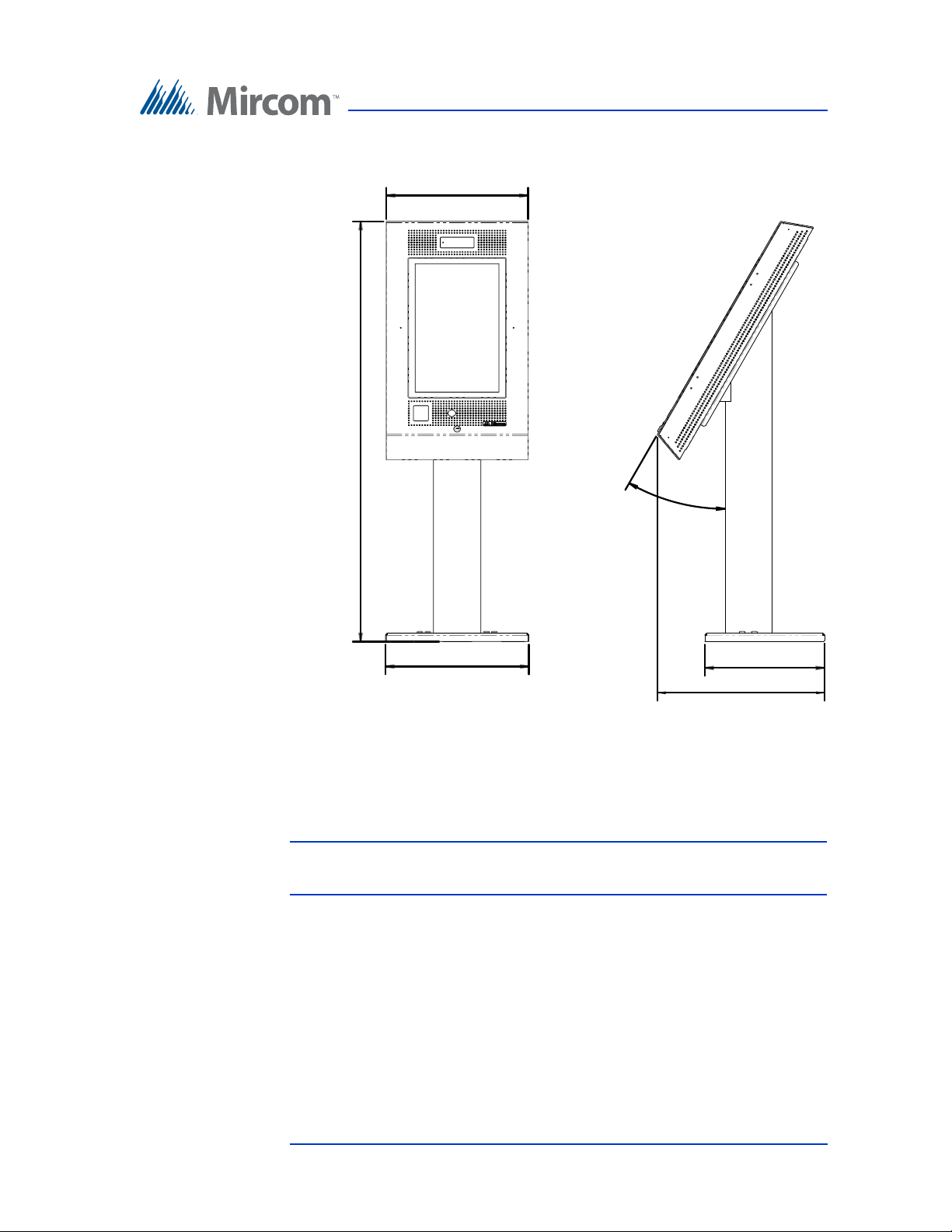
18.20
53.35
18.00
30°
15.19
21.23
Enclosure Installation
Figure 18. 22” Touch Screen Dimensions (inches)
The Kiosk mounts to the floor inside the building near the entrance, close to the
building power source and telephone infrastructure. Access for the power and
communication cables is provided through a cutout in the base plate.
Note: Avoid placing the Touch Screen in direct sunlight.
Install the power supply outside the enclosure.
The kit includes:
• 1 stand
• 1 base plate
• 8 #1/4-20 NC screws for attaching the stand to the base plate
• 8 screw covers
• 8 screw cover bases
Version 4.2 TX3 Touch Screen Installation Manual 37 (126)
LT-996 Copyright 2017
Page 38
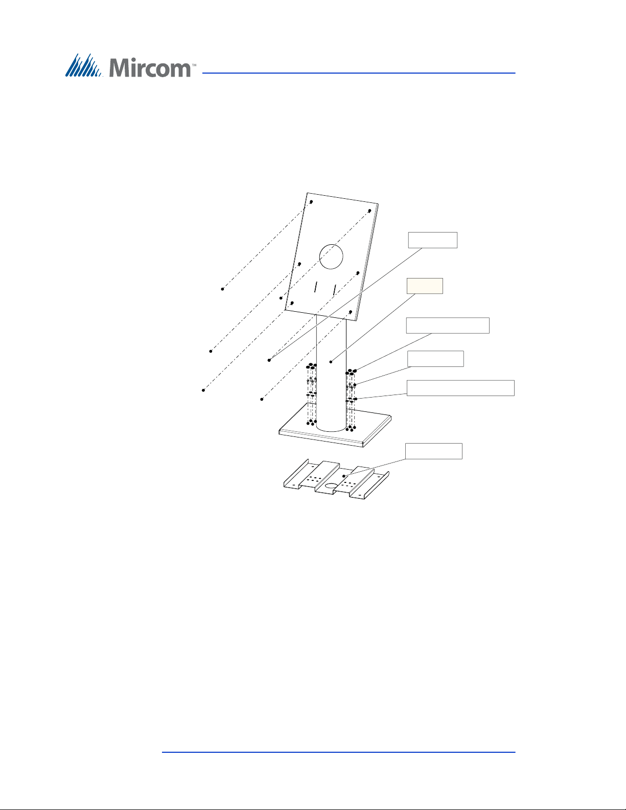
Enclosure Installation
Base plate
Screw cover base (x8)
Screw (x8)
Screw cover (x8)
Stand
Nuts (x6)
• 6 #8-32 nuts for attaching the Touch Screen to the stand
You will need:
• 4 bolts to attach the base plate to the floor. The bolts need to fit holes that
are 0.406” in diameter.
Figure 19. Components of TX3-T-KIOSK
1. Ensure that the base plate is aligned with the electrical conduit.
38 (126) TX3 Touch Screen Installation Manual Version 4.2
LT-996 Copyright 2017
Page 39
Enclosure Installation
10.300
14.244
2.500
2.450
2.107
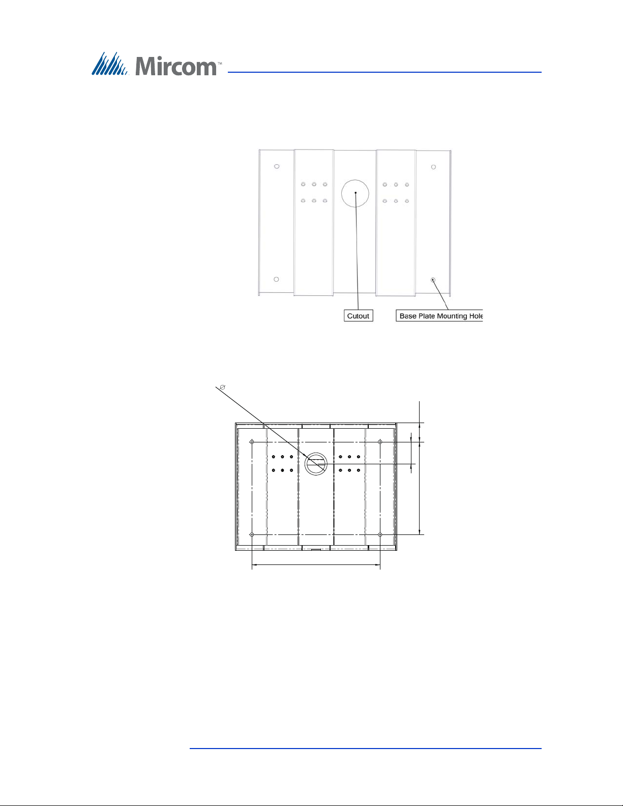
2. Using the base plate as a template, trace an opening on the floor for the
cutout and mark the 4 base plate mounting hole locations as shown in
Figure 20.
Figure 20. Base Plate Mounting Holes
Figure 21 shows the dimensions of the base plate.
Figure 21. Base Plate Dimensions (inches)
3. Cut an opening in the floor for the electrical and communication cables.
4. Run the wires through the base plate opening.
5. Secure the base plate to the floor using 4 bolts in the base plate mounting
holes shown in Figure 20. The holes are 0.406” in diameter.
Version 4.2 TX3 Touch Screen Installation Manual 39 (126)
LT-996 Copyright 2017
Page 40
Enclosure Installation
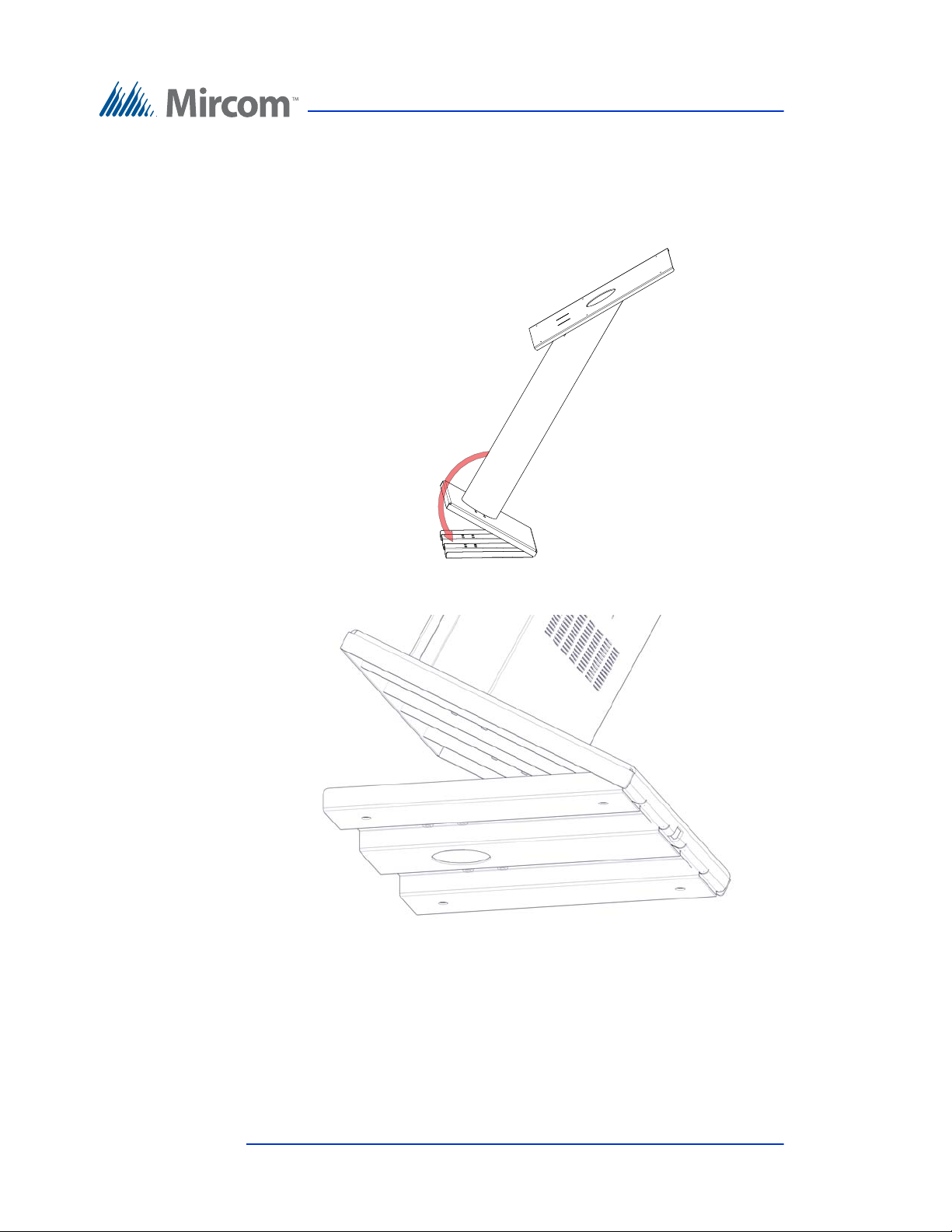
To fit the TX3-T-KIOSK stand on the base plate
1. Fit the back lip of the stand into the notches in the baseplate, and tilt the
stand forwards so that it rests on top of the base plate.
Figure 22. Fit the stand on the Base Plate
Figure 23. Fit the stand on the Base Plate (from below)
40 (126) TX3 Touch Screen Installation Manual Version 4.2
LT-996 Copyright 2017
Page 41
Enclosure Installation
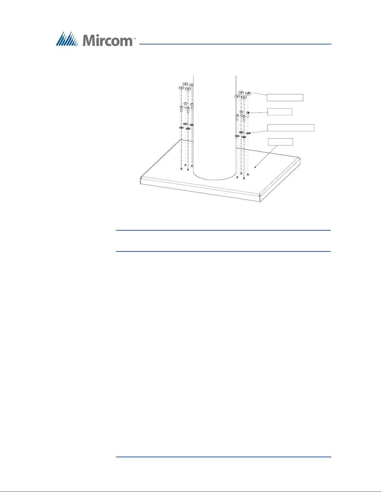
2. Secure the stand onto the base plate using the screw cover bases, screws,
and screw covers as show in Figure 24.
Screw cover (x8)
Screw (x8)
Screw cover base (x8)
Base plate
Figure 24. Attach the stand to the base plate
Attention: The 22” Touch Screen enclosure is heavy. Never attempt to lift this
product by yourself. At least two people should lift it together.
3. Fit the Touch Screen on the six posts on the stand.
Version 4.2 TX3 Touch Screen Installation Manual 41 (126)
LT-996 Copyright 2017
Page 42
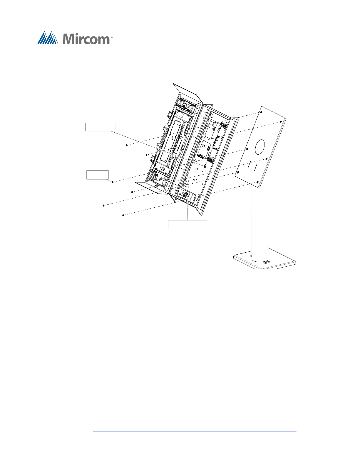
4. Attach the six included screws to the posts.
Nuts (x6)
Power and ground
Hole for wiring
Enclosure Installation
Figure 25. Attach the 22” Touch Screen to the stand
5. Proceed with the power supply installation described in section 2.11 on
page 63.
42 (126) TX3 Touch Screen Installation Manual Version 4.2
LT-996 Copyright 2017
Page 43
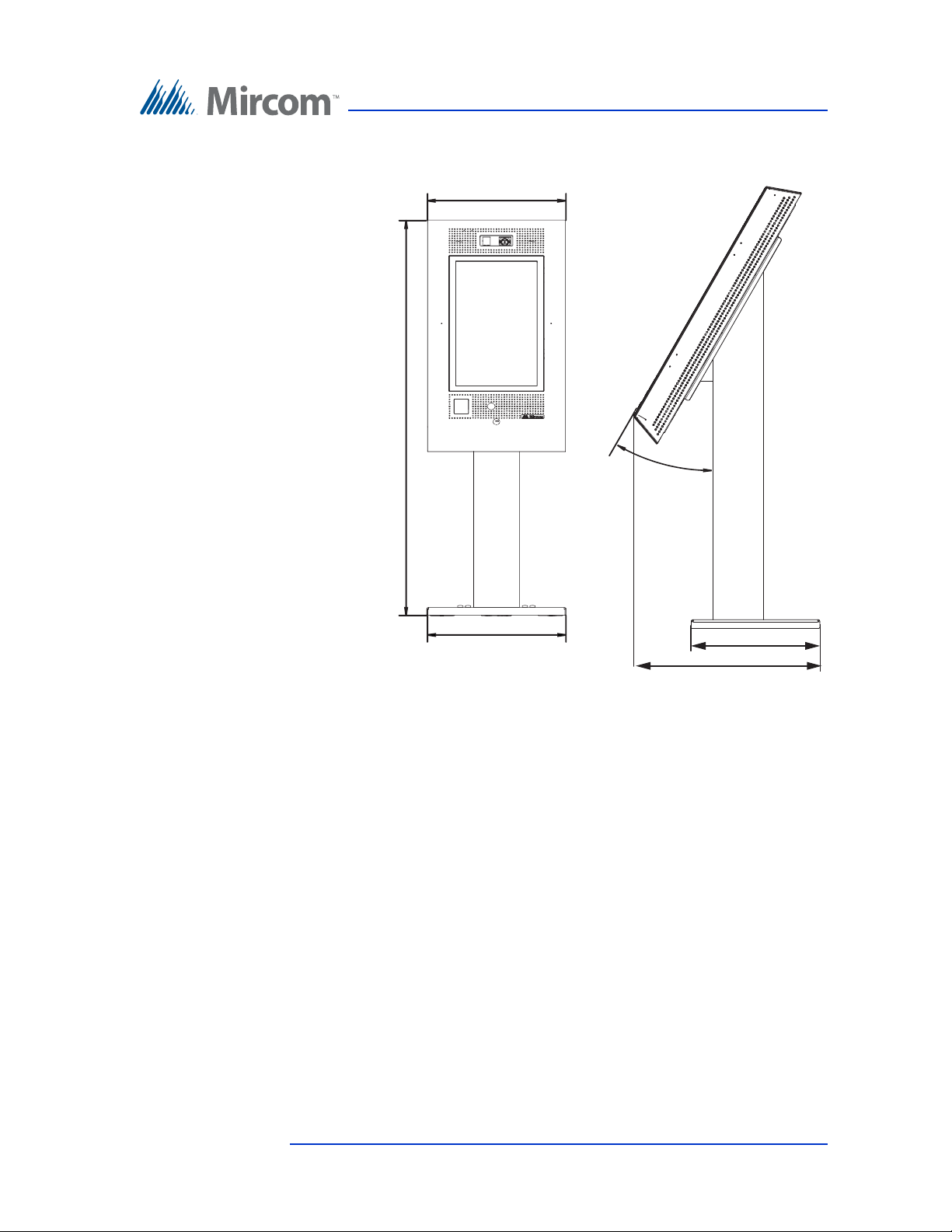
2.8 Installing TX3-T-KIOSK2
18” (457 mm)
51 23/32” (1313 mm)
18 13/64” (462 mm)
Enclosure Installation
30°
15 3/16” (386 mm)
22 3/16” (563 mm)
Figure 26. Dimensions of TX3-T-KIOSK2 with TX3-TOUCH-S22
Version 4.2 TX3 Touch Screen Installation Manual 43 (126)
LT-996 Copyright 2017
Page 44
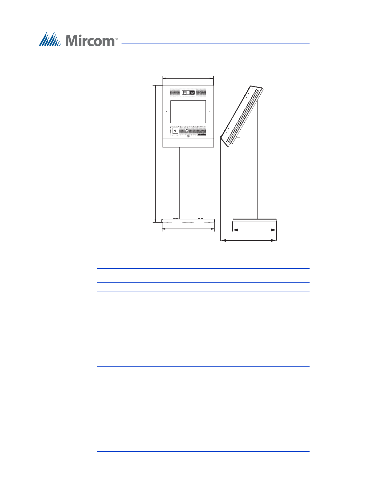
17 1/2” (445 mm)
47 1/16” (1195 mm)
Enclosure Installation
15 3/16” (386 mm)
18 13/64” (462 mm)
Figure 27. Dimensions of TX3-T-KIOSK2 with TX3-TOUCH-S15-B
19 9/16” (497 mm)
Note: TX3-TOUCH-S15-A can also be used with this stand.
Attention: The stand is heavy. Never attempt to lift this product by
yourself. At least two people should lift it together.
To ensure that there is enough room for installing the stand,
leave at least 4” (102 mm) clearance between the back of the
floor bracket and the wall.
Avoid placing the Touch Screen in direct sunlight.
Install the power supply outside the enclosure.
The Kiosk mounts to the floor inside the building near the entrance, close to the
building power source and telephone infrastructure. Access for the power and
communication cables is provided through a cutout in the base plate.
The kit includes:
•1 x stand
44 (126) TX3 Touch Screen Installation Manual Version 4.2
LT-996 Copyright 2017
Page 45
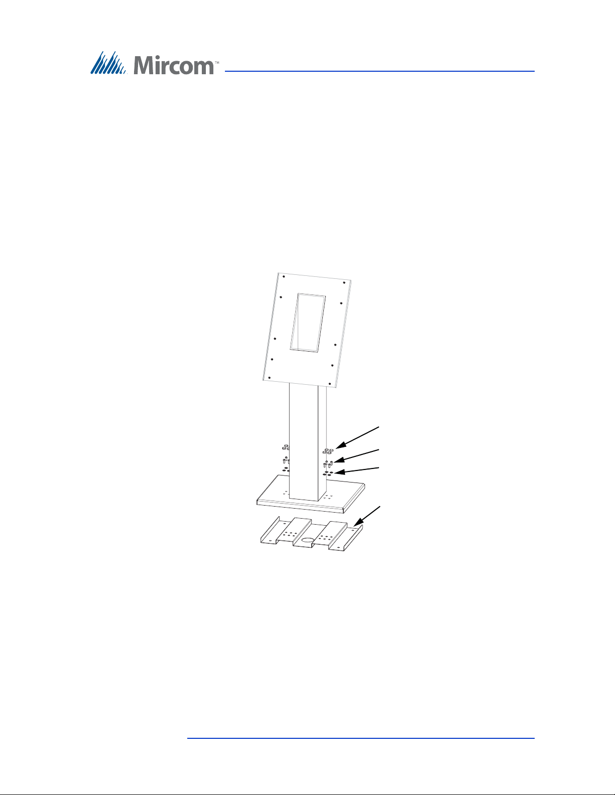
Enclosure Installation
Screw covers (x8)
Screws (x8)
Screw bases (x8)
Floor bracket
• 1 x floor bracket
• 8 x screws for attaching the stand to the floor bracket
• 8 x screw covers
• 8 x screw bases
• 6 x screws for attaching the Touch Screen to the stand
Weight: 65.5 lb (30 kg)
You need:
• 4 bolts to attach the base plate to the floor. The bolts need to fit holes that
are 13/32” (10 mm) in diameter.
Figure 28. Components of TX3-T-KIOSK2
1. Ensure that the base plate is aligned with the electrical conduit.
2. Using the base plate as a template, trace an opening on the floor for the
cutout and mark the 4 floor bracket mounting hole locations.
Version 4.2 TX3 Touch Screen Installation Manual 45 (126)
LT-996 Copyright 2017
Page 46
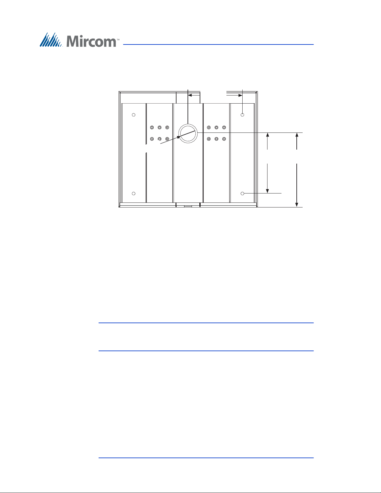
Figure 29 shows the dimensions of the floor bracket.
Front
Back
7 1/8”
(181 mm)
Enclosure Installation
Ø 2” (51 mm)
Figure 29. TX3-T-KIOSK2 Dimensions (from below)
7 27/32”
(199 mm)
9 5/8”
(245 mm)
3. Cut an opening in the floor for the electrical and communication cables.
4. Run the wires through the floor bracket opening.
5. Secure the floor bracket to the floor using 4 bolts in the floor bracket
mounting holes shown in Figure 29. The holes are 13/32” (10 mm) in
diameter.
To fit the TX3-T-KIOSK2 stand on the floor bracket
Attention: The stand is heavy. Never attempt to lift this product by
yourself. At least two people should lift it together. It weighs
65.5 lb (30 kg).
1. Run the wires through the stand and out the hole at the top.
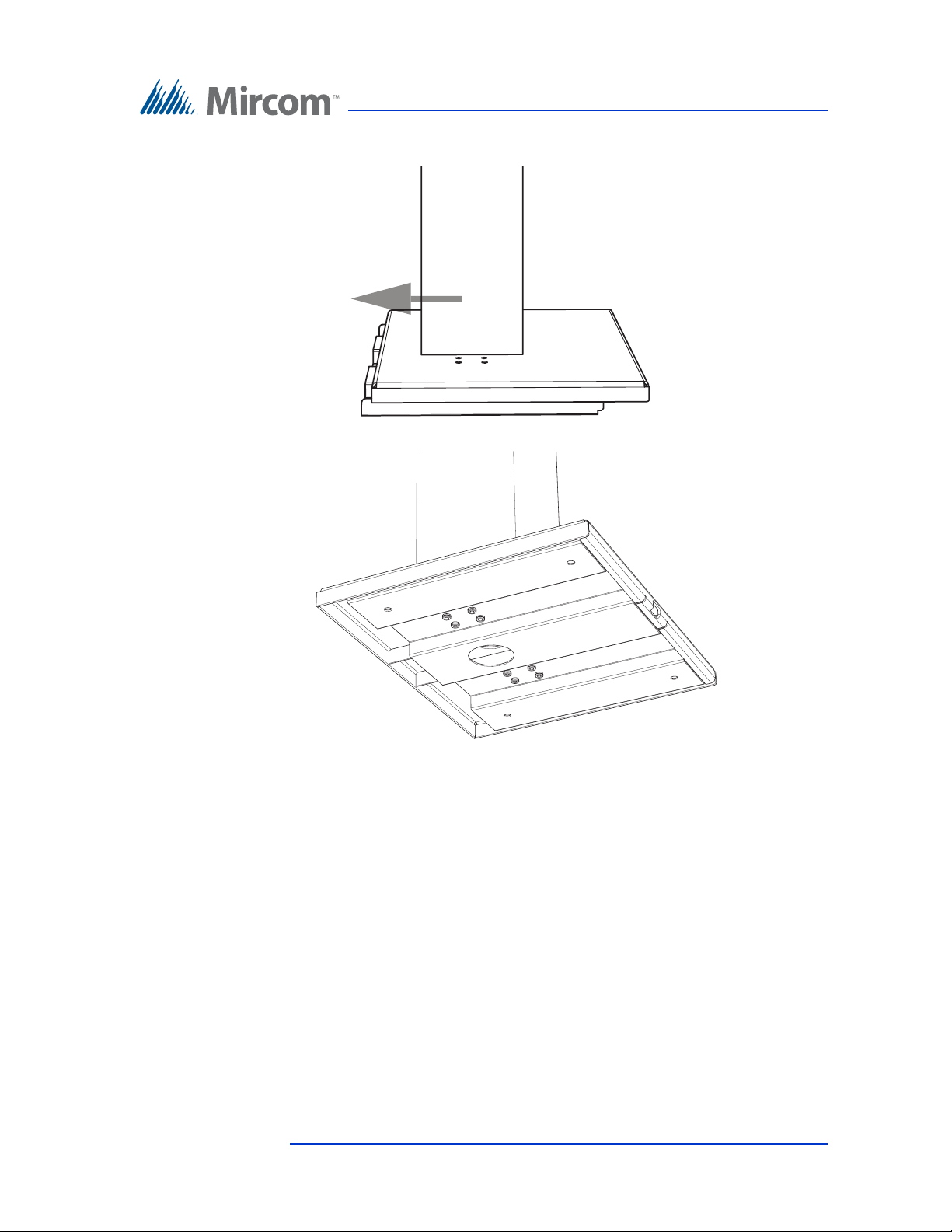
2. Place the stand on the floor bracket, and slide it forwards so that it rests on
top of the floor bracket.
46 (126) TX3 Touch Screen Installation Manual Version 4.2
LT-996 Copyright 2017
Page 47
Enclosure Installation
3. Ensure that the floor bracket fits into the back lip of the stand..
Figure 30. Fit the stand on the floor bracket
Figure 31. Fit the stand on the floor bracket (as seen from below)
Version 4.2 TX3 Touch Screen Installation Manual 47 (126)
LT-996 Copyright 2017
Page 48
Enclosure Installation
Screw covers (x8)
Screws (x8)
Screw bases (x8)
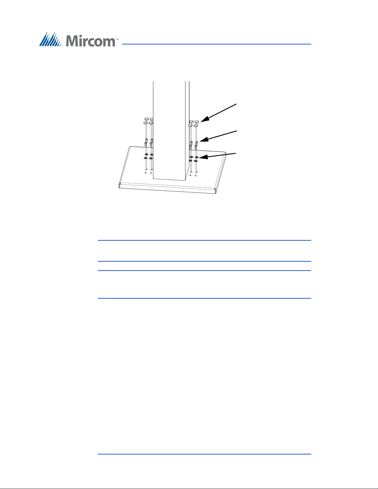
4. Secure the stand onto the floor bracket using the screw cover bases,
screws, and screw covers as show in Figure 32.
Figure 32. Attach the stand to the floor bracket
To mount the Touch Screen on the stand
Note: Use only surface mount Touch Screen (TX3-TOUCH-S22, TX3-
TOUCH-S15, TX3-TOUCH-S15-B) with this stand.
Attention: The 22” Touch Screen enclosure is heavy. Never attempt to lift
this product by yourself. At least two people should lift it
together. It weighs 65.5 lb (30 kg).
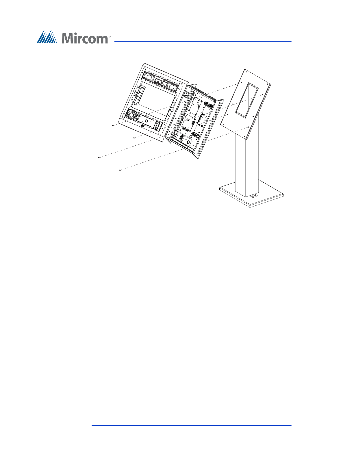
1. Align the top two mounting holes of the Touch Screen with the top holes
on the stand. See Figure 33.
2. Insert screws into the Touch Screen’s top mounting holes and lower the
Touch Screen so that the screws fit in the narrow part of the mounting
holes.
3. Secure the Touch Screen with the remaining screws. Use 6 screws for the
22” Touch Screen and 4 screws for the 15” Touch Screen.
4. Proceed with the power supply installation described in section 2.11 on
page 63.
48 (126) TX3 Touch Screen Installation Manual Version 4.2
LT-996 Copyright 2017
Page 49
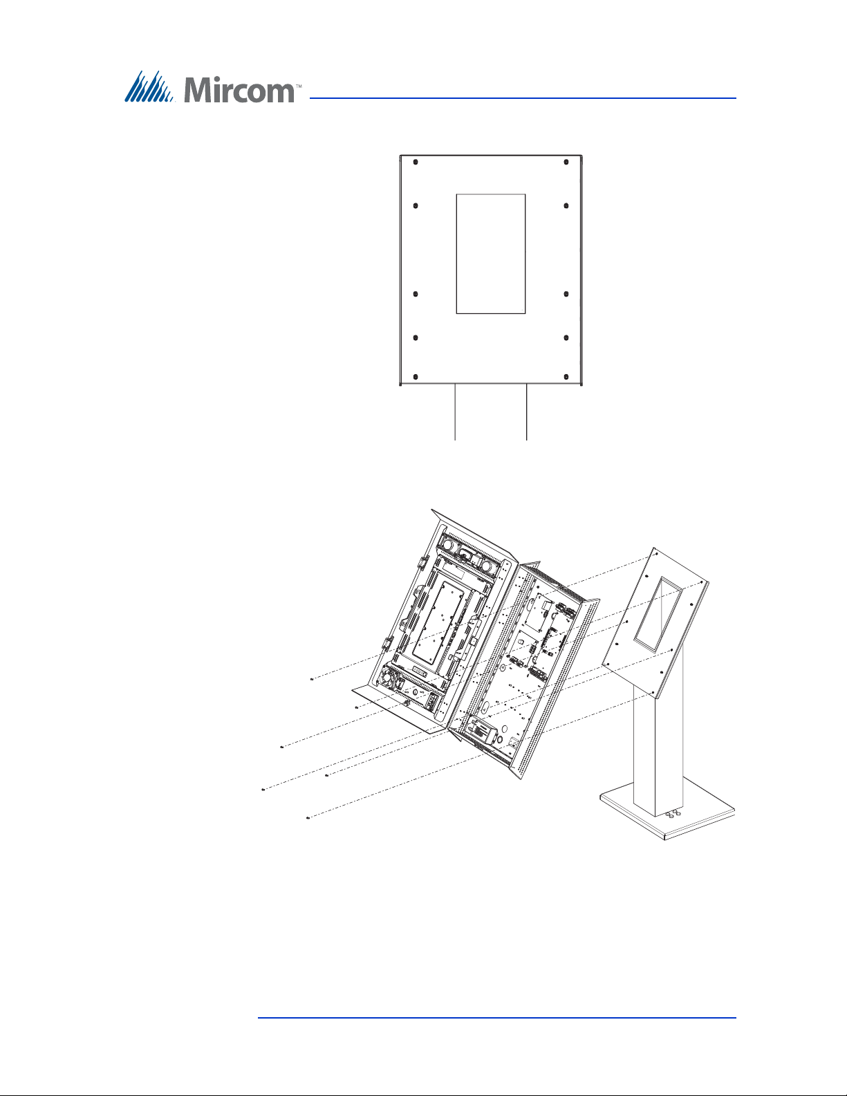
Figure 33. Mounting holes
Mount the 22”
Touch Screen on
holes 1, 3 and 5.
Mount the 15”
Touch Screen on
holes 2 and 4.
1
2
3
4
5
1
2
3
4
5
Enclosure Installation
Figure 34. Mount TX3-TOUCH-S22 on the stand
Version 4.2 TX3 Touch Screen Installation Manual 49 (126)
LT-996 Copyright 2017
Page 50
Enclosure Installation
Figure 35. Mount TX3-TOUCH-S15-B on the stand
50 (126) TX3 Touch Screen Installation Manual Version 4.2
LT-996 Copyright 2017
Page 51
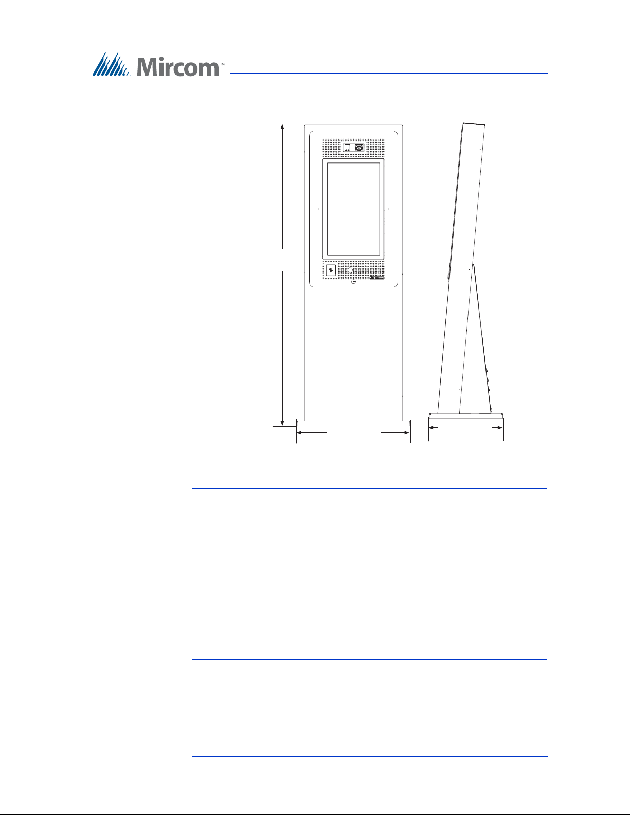
2.9 Installing TX3-T-KIOSK3
61 11/32”
(1558 mm)
Enclosure Installation
23 1/4” (591 mm)
Figure 36. Dimensions of TX3-T-KIOSK3
15 1/4” (387 mm)
Attention: The stand is heavy. Never attempt to lift this product by
yourself. At least two people should lift it together.
To ensure that there is enough room for installing the stand,
leave at least 4” (102 mm) clearance between the back of the
floor bracket and the wall.
To ensure that there is enough room for opening the door after
the stand is installed, leave at least 25” (635 mm) clearance
between the back of the fl oor bracket and the wall.
Avoid placing the Touch Screen in direct sunlight.
Install the power supply outside the enclosure.
The Kiosk mounts to the floor inside the building near the entrance, close to the
building power source and telephone infrastructure. Access for the power and
communication cables is provided through a cutout in the base plate.
Version 4.2 TX3 Touch Screen Installation Manual 51 (126)
LT-996 Copyright 2017
Page 52
Enclosure Installation
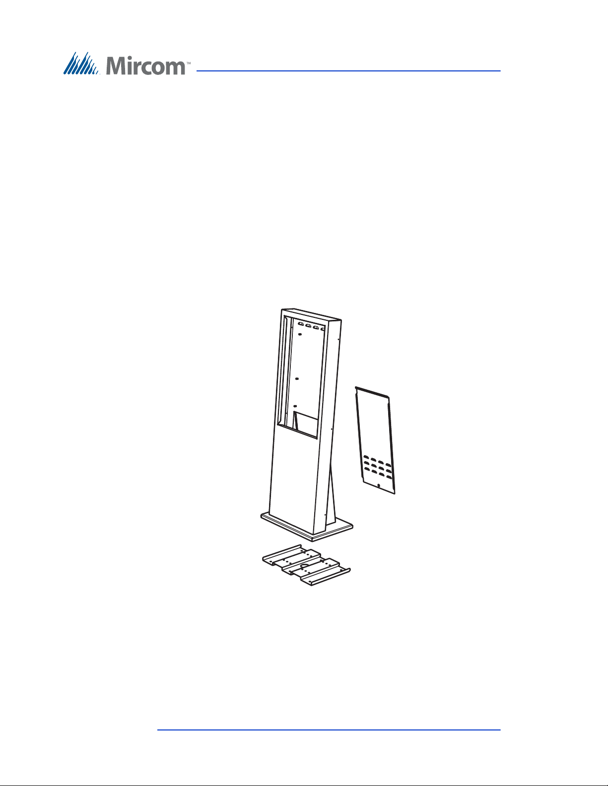
The kit includes:
• 1 x pedestal
• 1 x floor bracket
• 1 x door
• 6 x #8-32 x 1/4 screws for attaching the Touch Screen
• 12 x #1/4-20 x 5/8 screws for attaching the stand to the floor bracket
• 2 x keys
Weight: 74 lb (34 kg)
You will need:
• 4 bolts to attach the base plate to the floor. The bolts need to fit holes that
are 13/32” (10 mm) in diameter.
Figure 37. Components of TX3-T-KIOSK3
To attach the floor bracket to the floor
1. Ensure that the floor bracket is aligned with the electrical conduit.
52 (126) TX3 Touch Screen Installation Manual Version 4.2
LT-996 Copyright 2017
Page 53
Enclosure Installation
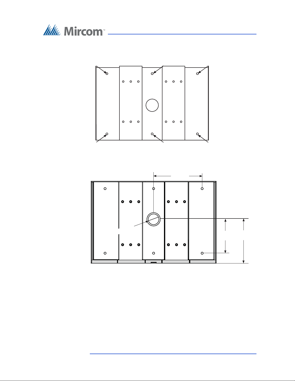
6 19/64”
(160 mm)
Ø 2” (51 mm)
8 11/64”
(207 mm)
9”
(228 mm)
Front
Back
2. Using the floor bracket as a template, trace an opening on the floor for the
cutout and mark the 6 floor bracket mounting hole locations as shown in
Figure 38.
Figure 38. Floor Bracket Mounting Holes
Figure 39. TX3-T-KIOSK3 Dimensions (from below)
1. Cut an opening in the floor for the electrical and communication cables.
2. Run the wires through the floor bracket opening.
3. Secure the floor bracket to the floor using 6 bolts through the floor bracket
mounting holes shown in Figure 38. The holes are 13/32” (10 mm) in
diameter.
Version 4.2 TX3 Touch Screen Installation Manual 53 (126)
LT-996 Copyright 2017
Page 54
Enclosure Installation
To fit the TX3-T-KIOSK3 stand on the floor bracket
Attention: The stand is heavy. Never attempt to lift this product by
yourself. At least two people should lift it together. It weighs 74
lb (34 kg).
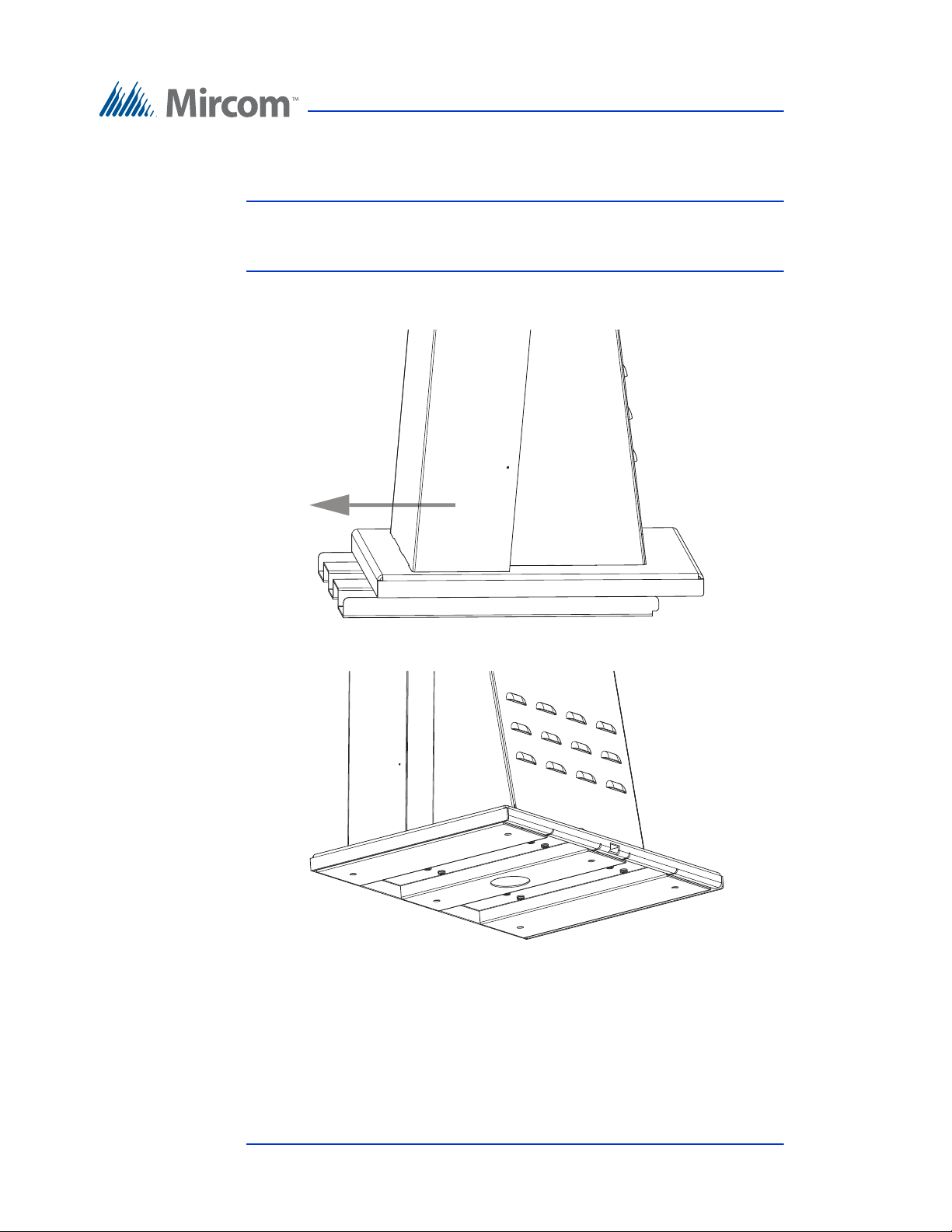
1. Fit the back lip of the stand into the notches in the floor bracket, and tilt the
stand forwards so that it rests on top of the floor bracket.
Figure 40. Fit the stand on the floor bracket
Figure 41. Fit the stand on the floor bracket (from below)
54 (126) TX3 Touch Screen Installation Manual Version 4.2
LT-996 Copyright 2017
Page 55
Enclosure Installation
To fit the Touch Screen on the stand
Attention: Use only the 22 inch flush mount Touch Screen (TX3-TOUCH-
F22) with this stand.
Attention: The 22” Touch Screen enclosure is heavy. Never attempt to lift
this product by yourself. At least two people should lift it
together.
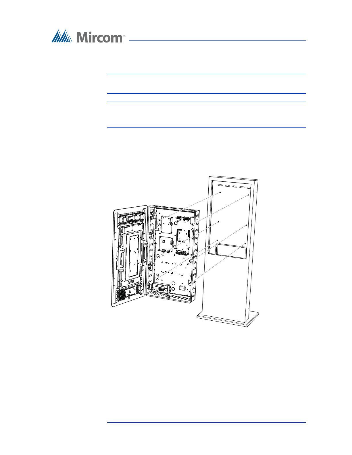
1. Fit the Touch Screen on the six studs on the stand.
2. Attach the 6 included screws to the studs.
3. Run the wires through the knockout at the bottom of the Touch Screen.
Figure 42. Mount TX3-TOUCH-S22 on the stand
Version 4.2 TX3 Touch Screen Installation Manual 55 (126)
LT-996 Copyright 2017
Page 56
To Attach the door
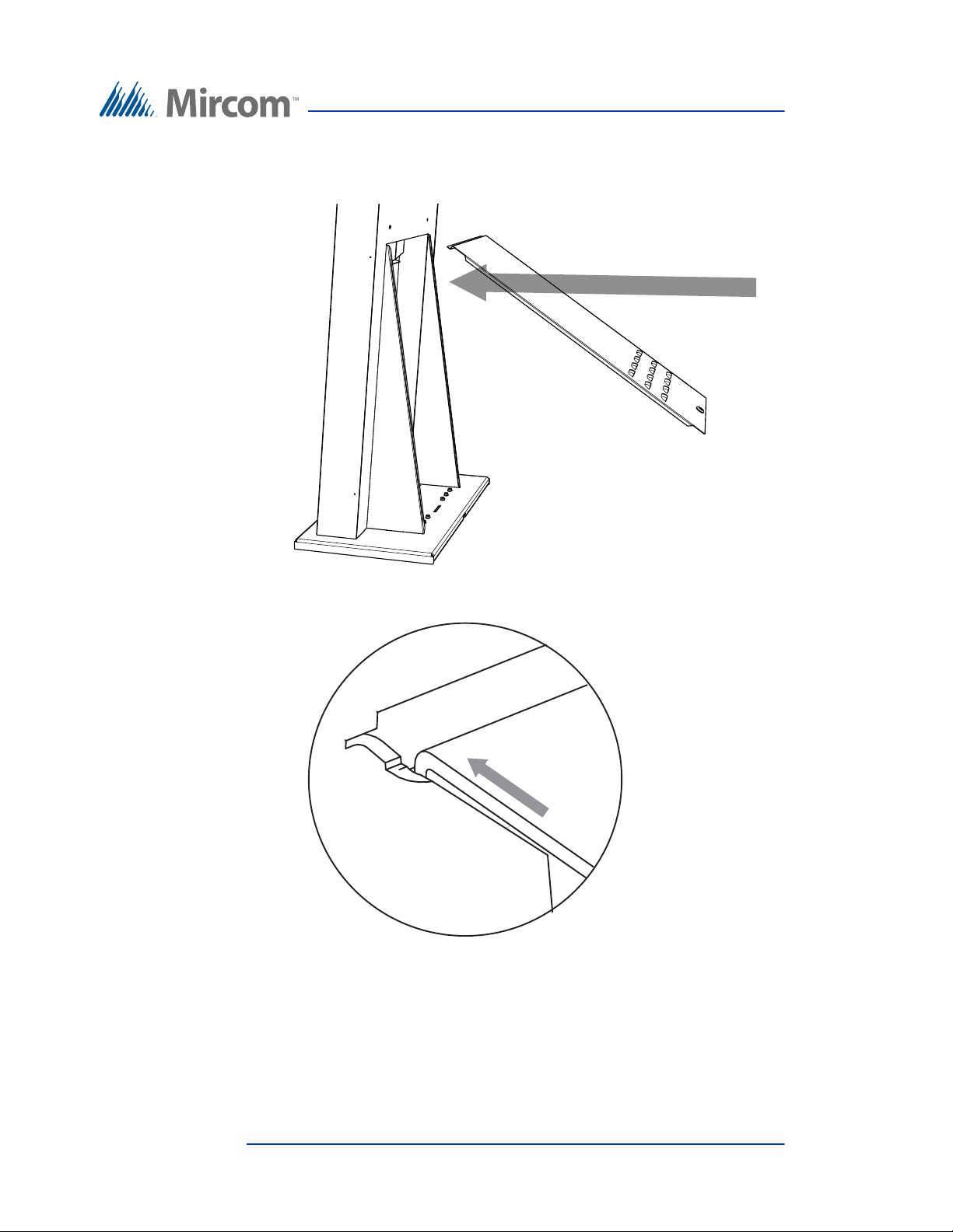
1. Fit the door into the opening so that it rests on the ledge.
Enclosure Installation
Figure 43. Fit the door on the stand
Figure 44. Close-up showing the door fitting on the ledge
56 (126) TX3 Touch Screen Installation Manual Version 4.2
LT-996 Copyright 2017
Page 57
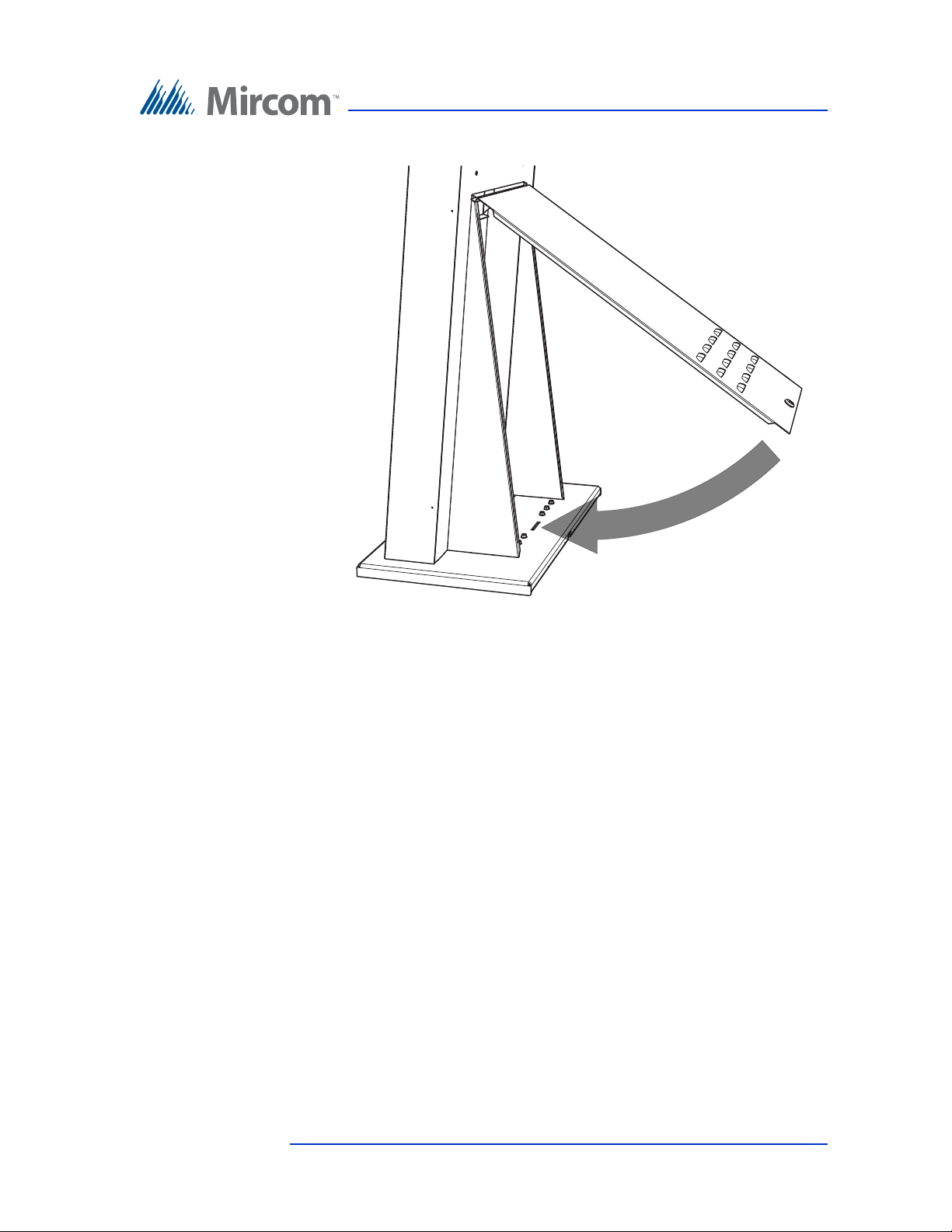
2. Swing the door down and lock it.
Enclosure Installation
Figure 45. Swing the door closed
3. Proceed with the power supply installation described in section 2.11 on
page 63.
Version 4.2 TX3 Touch Screen Installation Manual 57 (126)
LT-996 Copyright 2017
Page 58
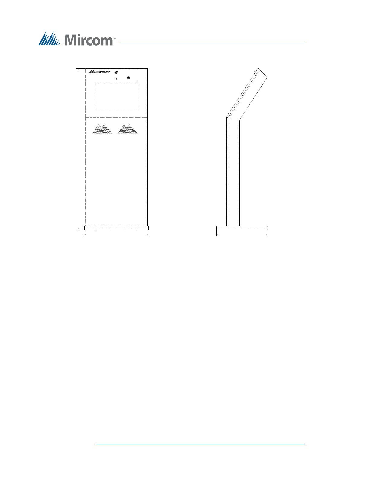
2.10 Installing TX3-TOUCH-K15-A
50.0
Enclosure Installation
17.950
Figure 46. Kiosk Dimensions (inches)
14.187
The Kiosk mounts to the floor inside the building near the entrance, close to the
power source and telephone infrastructure. Access for the power and
communication cables is provided through a cutout in the base plate.
To install the Kiosk you must:
• Remove the reinforcement bracket and the base plate.
• Attach the base plate to the floor, and run the wiring through the base plate
opening.
• Attach the Kiosk to the base plate.
• Attach the reinforcement bracket to the Kiosk.
Follow the instructions below to complete these steps.
You will need:
4 bolts to attach the base plate to the floor. The holes in the base plate are 0.406”
in diameter.
58 (126) TX3 Touch Screen Installation Manual Version 4.2
LT-996 Copyright 2017
Page 59
Enclosure Installation
To install the Touch Screen Kiosk base plate
1. Find a suitable location for the Kiosk next to the building entrance and
above the building electrical and communications conduit.
2. Remove the door from the Kiosk.
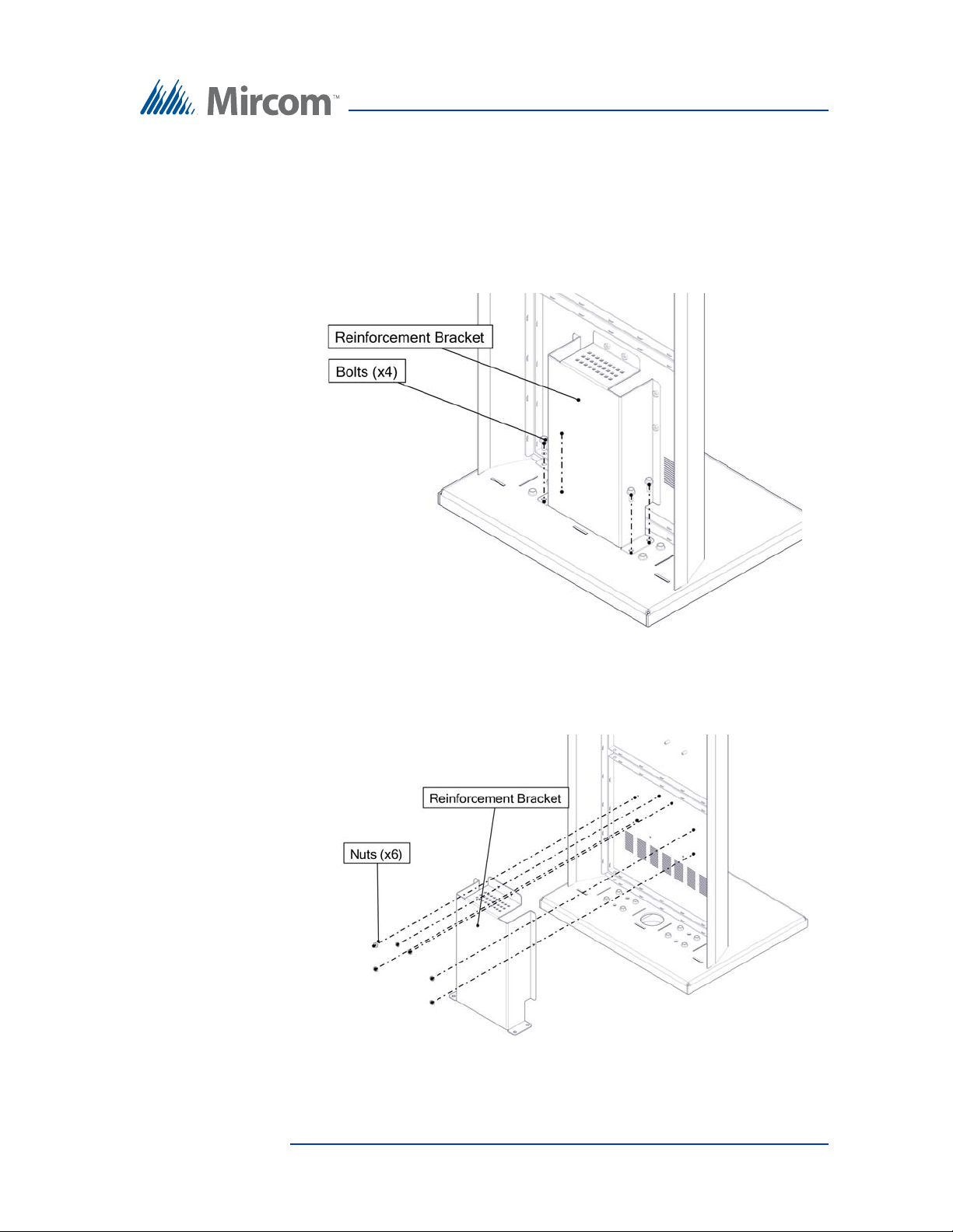
3. Remove the 4 bolts from the reinforcement bracket, as shown in Figure 47.
Figure 47. Reinforcement Bracket with bolts
4. Remove the 6 nuts on the reinforcement bracket, as show in Figure 48, and
then remove the bracket.
Figure 48. Reinforcement Bracket with nuts
Version 4.2 TX3 Touch Screen Installation Manual 59 (126)
LT-996 Copyright 2017
Page 60
Enclosure Installation
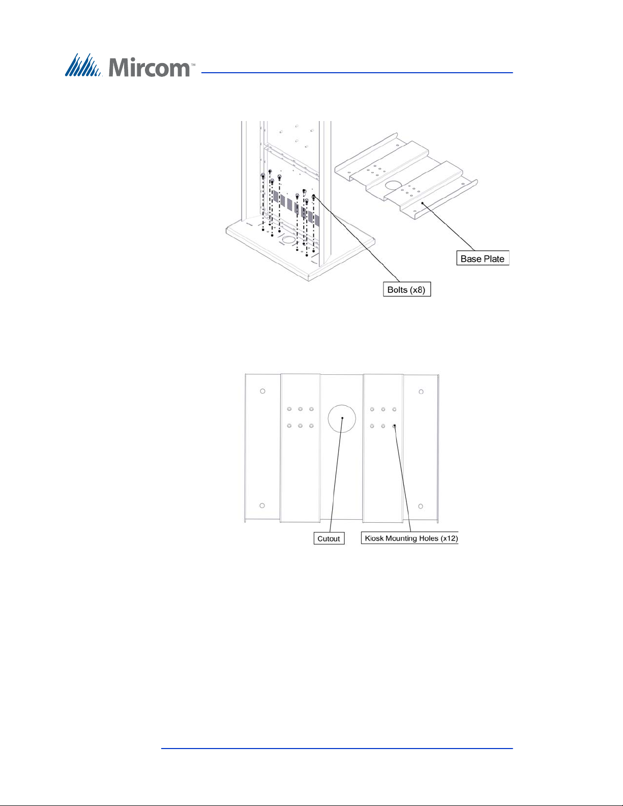
5. Remove the remaining 8 bolts that attach the Kiosk to the base plate, as
shown in Figure 49.
Figure 49. Kiosk Base Plate with bolts
The 12 Kiosk mounting holes in the base plate are shown in Figure 50.
Figure 50. Kiosk Mounting Holes
60 (126) TX3 Touch Screen Installation Manual Version 4.2
LT-996 Copyright 2017
Page 61
Enclosure Installation
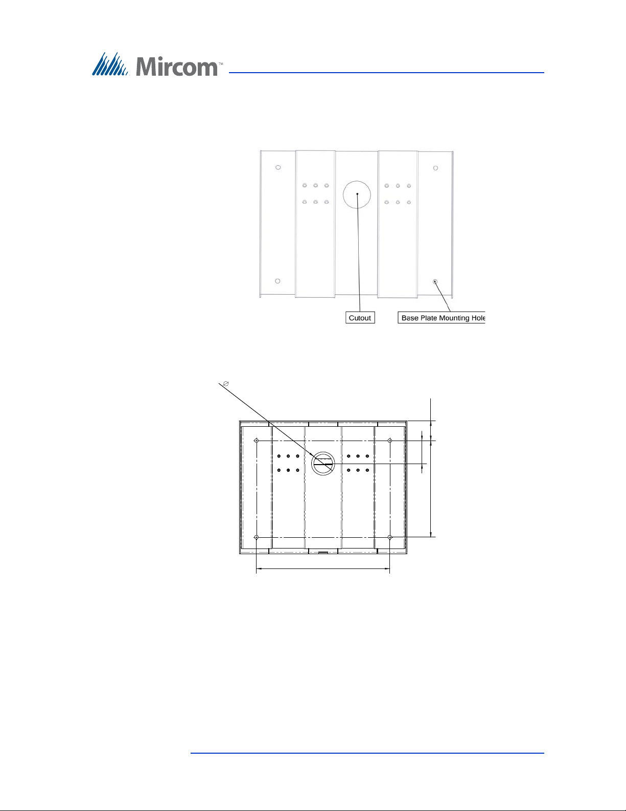
10.300
14.244
2.500
2.450
2.107
6. Using the Kiosk base plate as a template, trace an opening in the floor for
the cutout and mark the 4 base plate mounting hole locations as shown in
Figure 51. Ensure that the base plate is aligned with the electrical conduit.
Figure 51. Base Plate Mounting Holes
Figure 52 shows the dimensions of the base plate.
Figure 52. Base Plate Dimensions (inches)
7. Cut an opening in the floor for the electrical and communication cables.
8. Run the wires through the base plate opening.
9. Secure the base plate to the floor using 4 bolts in the base plate mounting
holes shown in Figure 51. The holes are 0.406” in diameter.
Version 4.2 TX3 Touch Screen Installation Manual 61 (126)
LT-996 Copyright 2017
Page 62
Enclosure Installation
To fit the Touch Screen Kiosk on the base plate
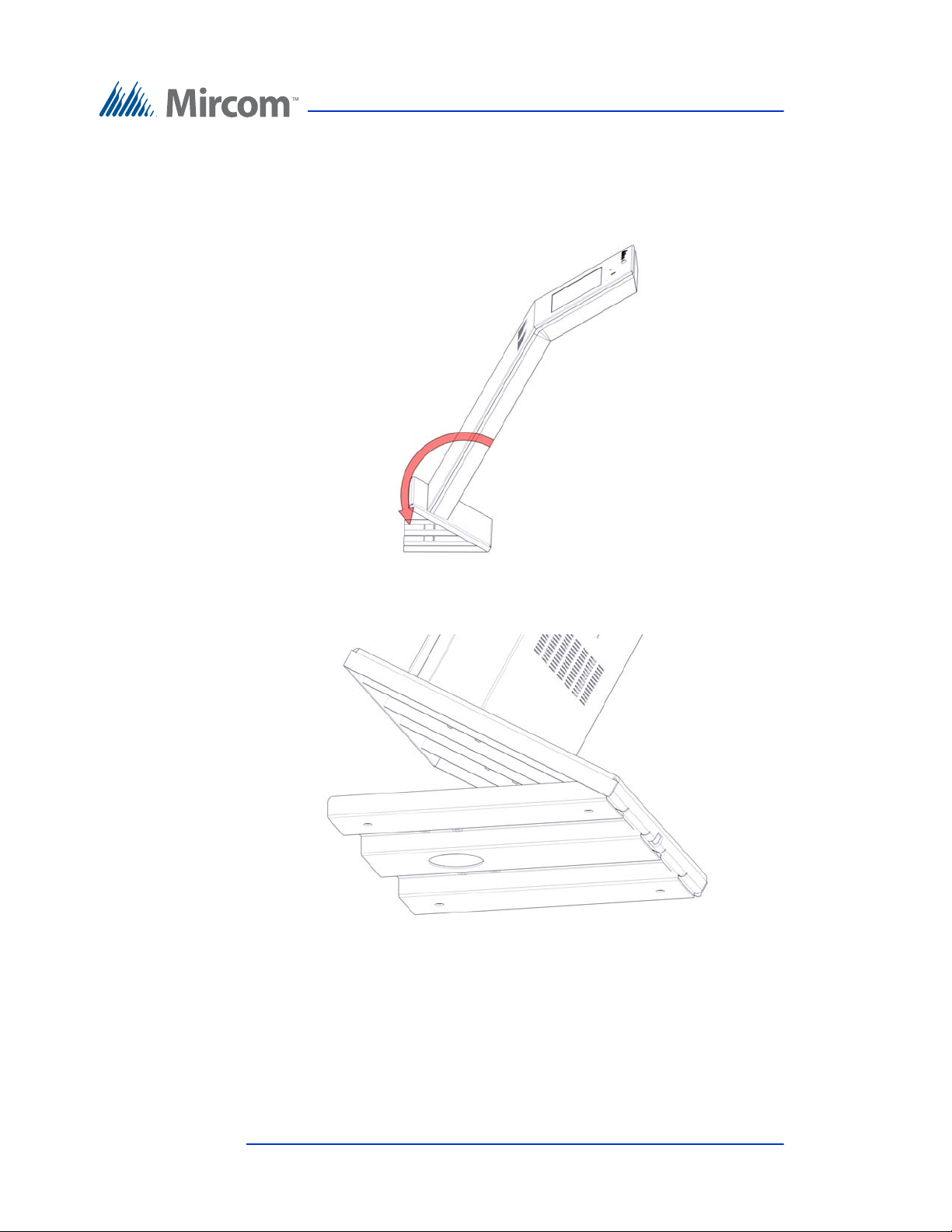
1. Fit the back lip of the Kiosk into the notches in the baseplate, and tilt the
Kiosk forwards so that it rests on top of the base plate.
Figure 53. Fitting the Kiosk on the Base Plate
Figure 54. Fitting the Kiosk on the Base Plate (from below)
62 (126) TX3 Touch Screen Installation Manual Version 4.2
LT-996 Copyright 2017
Page 63
Enclosure Installation
Attach the Kiosk to the base plate
with bolts in these holes rst
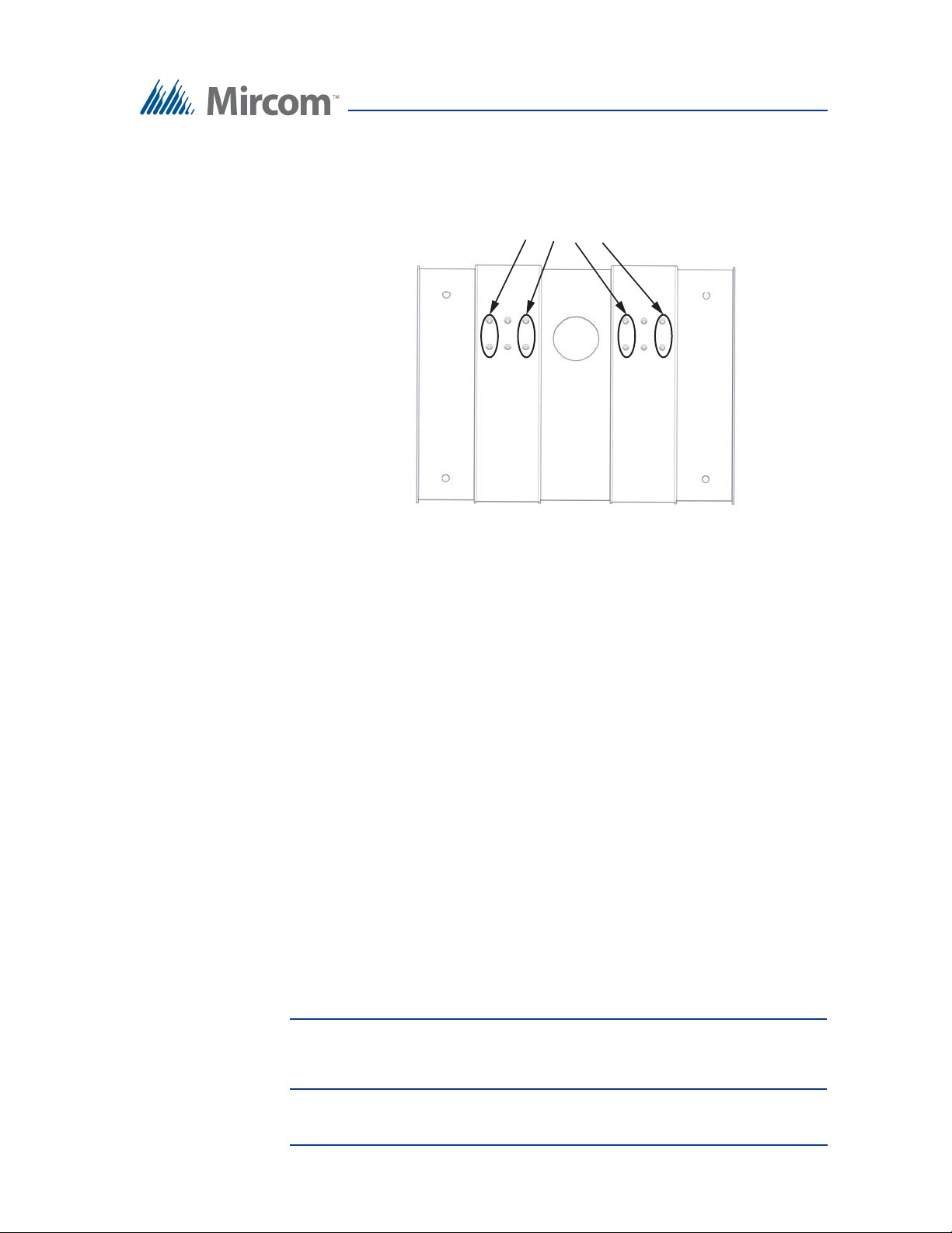
2. Secure the Kiosk onto the base plate using the 8 of the 12 base plate bolts
in the holes shown in Figure 55.
Figure 55. Attach the Kiosk to the base plate
3. Position the reinforcement bracket over the 6 studs on the inside of the
Kiosk, and screw the 6 nuts on to the studs as shown in Figure 48.
4. Secure the reinforcement bracket to the base plate using the remaining 4
base plate bolts in the remaining 4 holes in the base plate.
5. Fit the door to the Kiosk.
6. Proceed with the power supply installation described in section 2.11 on
page 63.
2.11 Installing the Power Supply Enclosure
The Touch Screen MD-990 external power supply is a 156 W, 24 V single output
switching power supply encased inside a metal enclosure. A voltage selectable
switch is located on the side of the power supply and is factory set to 120V but can
be switched to 230V.
To set the voltage on the Switching Power Supply
1. Ensure that the TX3 unit is off and that all power is disconnected.
Warning: The power must be turned off before the Switching Power
Supply is accessed. Failure to due so may result in damage to the
equipment or electric shock that can lead to death.
Version 4.2 TX3 Touch Screen Installation Manual 63 (126)
LT-996 Copyright 2017
Page 64
Enclosure Installation
L
N
V-
V+
V+
V-
230V
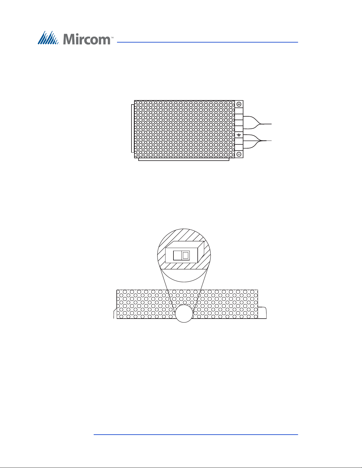
2. Open the Switching Power Supply box using the key for the TX3 unit. The
Switching Power Supply unit is secured inside the box by metal guides and
two screws on either side of the terminal block. Unscrew and remove the
screws on both sides of the terminal block.
Figure 56. Inside the Switching Power Supply Box
3. Lift the Switching Power Supply unit out of its box to access the red
voltage selection switch.
4. Switch the voltage selection switch to the required voltage level. Place a
flathead screwdriver in between one of the holes in the chassis to access the
switch. By default it is set to 115 Volts.
Figure 57. Power Supply Voltage Selection Switch
5. Place the Switching Power Supply back into the box using the metal
guides to position it and then replace the screws on both sides of the
terminal block to secure it into the box.
6. Reconnect the power.
64 (126) TX3 Touch Screen Installation Manual Version 4.2
LT-996 Copyright 2017
Page 65
Enclosure Installation
9 1/5” (241 mm)
7 1/5”
(191 mm)
7 3/4” (197 mm)
The external power supply connects to the building power AC power supply. It is
recommended that the unit is powered by its own dedicated electrical outlet to
protect it from excessive power surges and current fluctuations.
Note: Install the power supply outside the Touch Screen enclosure.
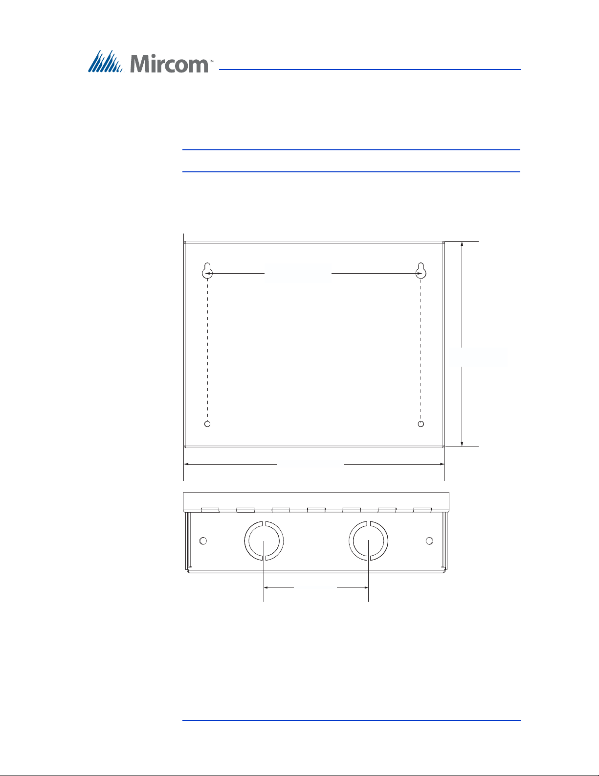
Overall dimensions: height: 7 23/32” (196 mm),
width: 9 53/64” (250 mm), depth: 2 37/64” (66 mm)
Knockout dimensions: 1 1/8” (29 mm) and 7/8” (22 mm)
3” (76 mm)
Figure 58. Power Supply Enclosure Dimensions
To surface mount the power supply enclosure
1. Find a suitable location for the power supply enclosure, such as over a wall
stud.
Version 4.2 TX3 Touch Screen Installation Manual 65 (126)
LT-996 Copyright 2017
Page 66
Enclosure Installation
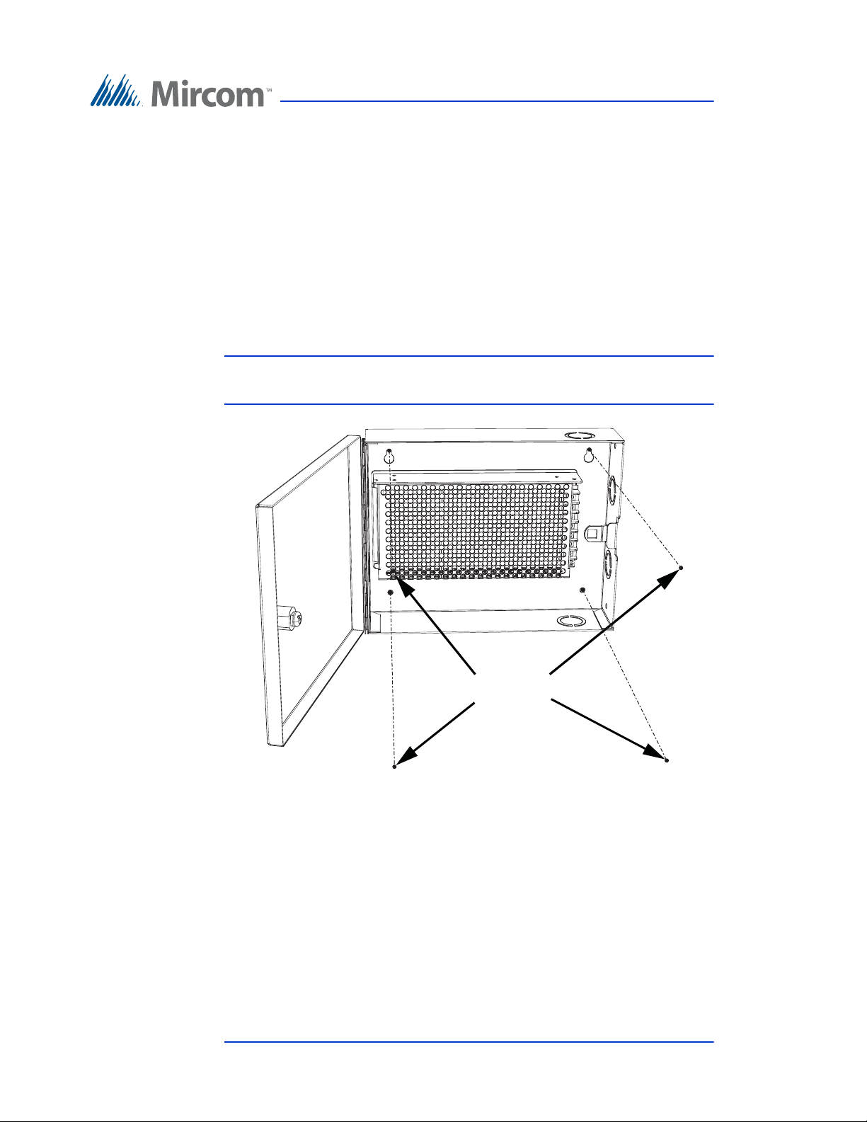
2. Using the power supply enclosure as a template, mark the back mounting
hole locations as indicated in Figure . Ensure that at least one side is over a
wall stud.
3. Remove the power supply enclosure and place the top two screws halfway
into the marked hole locations and wall stud using the supplied screws.
4. Place the power supply enclosure onto the two screws.
5. Screw the two screws of the power supply enclosure halfway into the wall.
6. Tighten all four screws into place.
Note: The enclosure can also be mounted directly onto the drywall using
anchors.
Screws
Figure 59. Power Supply Enclosure
66 (126) TX3 Touch Screen Installation Manual Version 4.2
LT-996 Copyright 2017
Page 67

3 Touch Screen System and Setup
This chapter describes the basic Touch Screen system, main panel, controller
board components and provides information about its operation and setup.
This chapter explains
• Touch Screen System
• TX3-TOUCH-K15-A, TX3-TOUCH-F15-A, TX3-TOUCH-S15-A Main
Panel, Boards, and Grounding
• TX3-TOUCH-F15-B and TX3-TOUCH-S15-B Inside Door, Boards, and
Grounding
• TX3-TOUCH-F22 and TX3-TOUCH-S22 Inside Door, Boards, and
Grounding
• Telephone Access Controller Board
• Connecting to the External Power Supply
• Turning the Touch Screen On and Off
• Installing the Postal Lock
• Installing the Telephone Lines
• Installing Optional Components
• Verifying Installed Components
• Beginning Configuration
• Installing the P1264 IP camera
• Replacing the Display on the 22” Touch Screen
• Installing the TX3-P300-HA Card Reader in the 22” Touch Screen
• Installing a RB-MD-1093 Two Door Controller Network Board
Version 4.2 TX3 Touch Screen Installation Manual 67 (126)
LT-996 Copyright 2017
Page 68

3.1 Touch Screen System
The TX3 Touch Screen may be networked with a combination of Telephone
Access and Card Access Units through a peer-to-peer RS-485 connection.
Touch Screen is capable of providing ADC or NSL telephone access from a
single panel or from a networked system. Each outside telephone line requires a
separate line to the control panel inside the Touch Screen.
The following figures depict various Touch Screen network scenarios.
Note: Install all transformers and power supplies outside the Touch
Screen enclosure.
All wiring is a maximum length of 1000 ft. The RS-485 wiring maximum length
is 4000 ft.
All units use the MD-990 power supply. Refer to section 2.11 Installing the
Power Supply Enclosure on page 63 or document LT-1094 Power Supply
Voltage Selection. The door strike power supply depends on the door strike
power requirements.
Touch Screen System and Setup
68 (126) TX3 Touch Screen Installation Manual Version 4.2
LT-996 Copyright 2017
Page 69
3.1.1 Single Touch Screen
Line1
NSL
Control
Unit
T/R
Line1
Telephone outlet
Central office line
OR
Touch Screen
Touch Screen
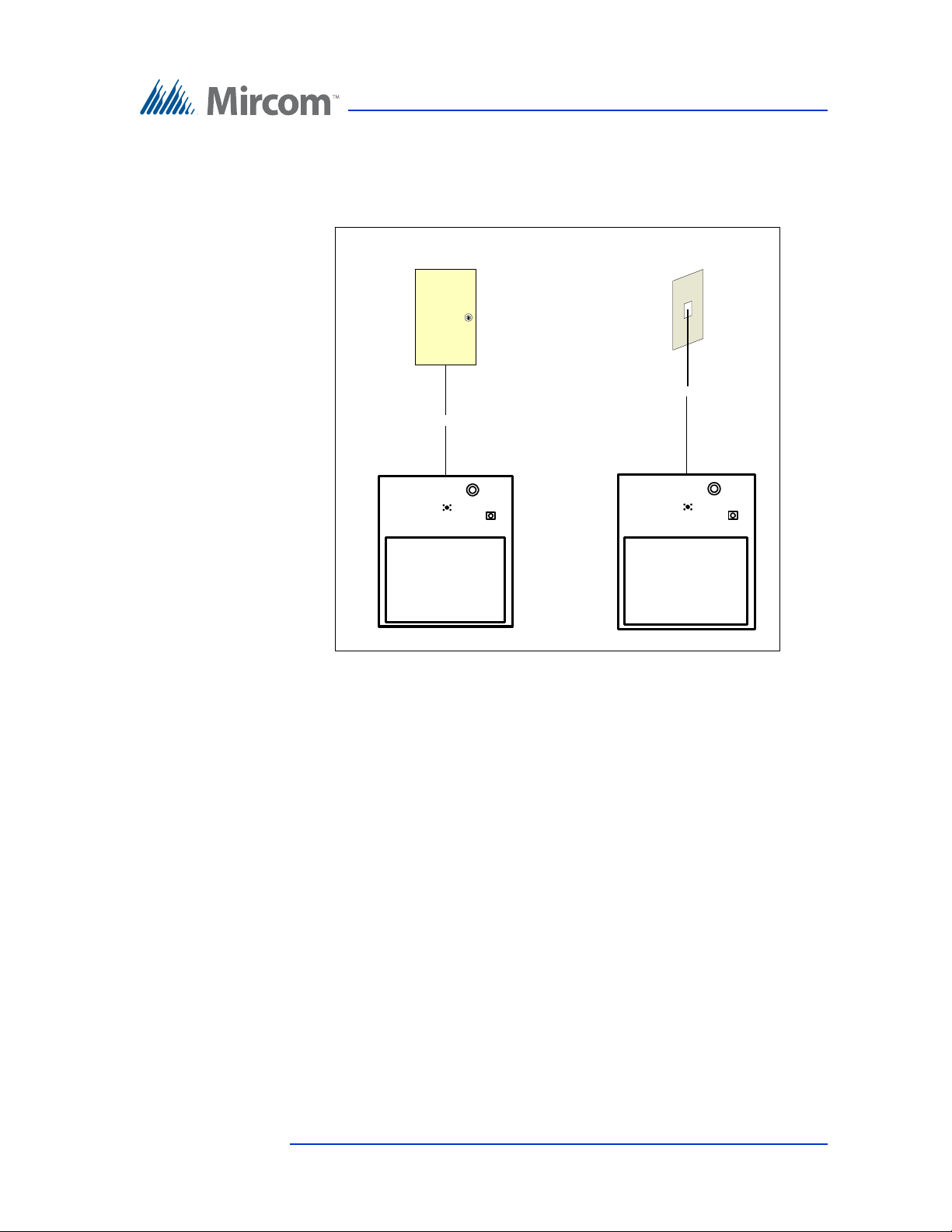
Figure 60 shows the simplest configuration for an ADC or NSL telephone
system.
Touch Screen System and Setup
Version 4.2 TX3 Touch Screen Installation Manual 69 (126)
LT-996 Copyright 2017
Figure 60. Single Touch Screen
Page 70
Touch Screen System and Setup
Line2
Line3
Line4
Line5
NSL
Control
Unit
NSL
Control
Unit
NSL
Control
Unit
NSL
Control
Unit
Line1
Telephone outlet
Central office line
T/R
T/R
T/R T/R
T/R
Touch Screen
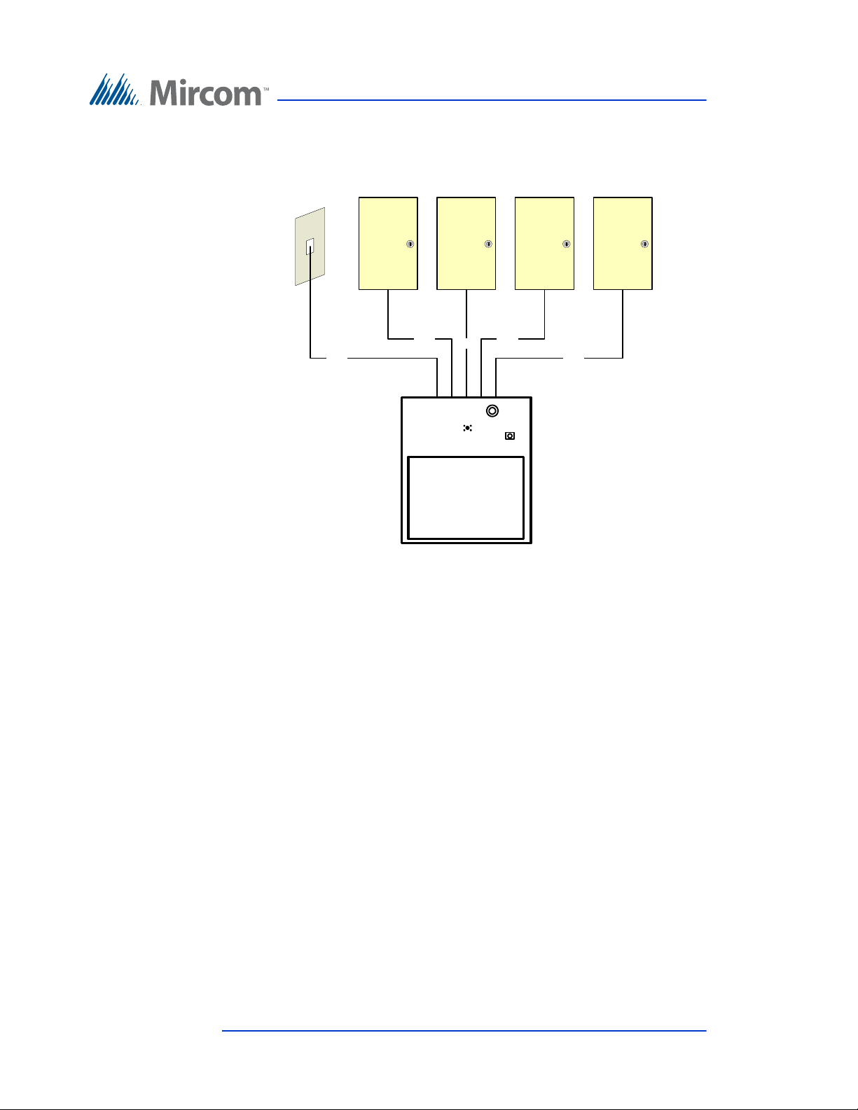
Figure 61 shows a configuration using one Touch Screen connected to one ADC
line and four NSL lines.
Figure 61. Single Touch Screen with ADC and NSL Lines
70 (126) TX3 Touch Screen Installation Manual Version 4.2
LT-996 Copyright 2017
Page 71
Touch Screen System and Setup
ON/OFF
Switch
USB Port
Camera
Postal Lock
Microphone
Touch Screen
Screw
Screw
3.2 TX3-TOUCH-K15-A, TX3-TOUCH-F15-A, TX3TOUCH-S15-A Main Panel, Boards, and
Grounding
3.2.1 Main Panel
On the Kiosk, the Touch Screen Panel is situated behind the front cover. To
access the panel, unlock the Touch Screen and pull open the front cover.
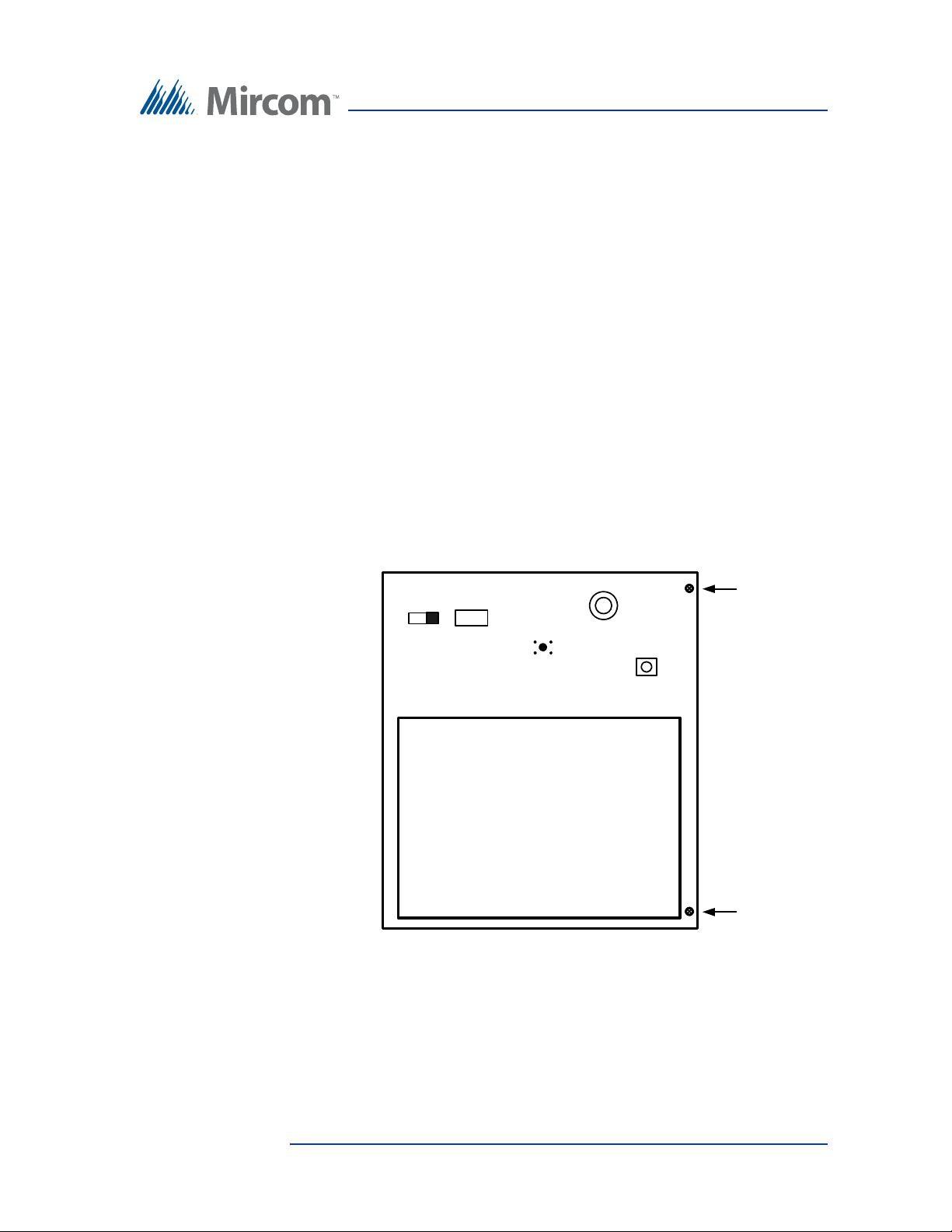
The 15” Touch Screen Panel contains the following main components as shown
in Figure 62:
• ON/OFF Switch
•USB Port
• Camera
•Postal Lock (optional)
• Microphone
Figure 62. 15” Touch Screen Panel Components
3.2.2 Controller Boards
The following Touch Screen controller boards are situated on a panel behind the
15” Touch Screen Panel as shown in Figure 63:
Version 4.2 TX3 Touch Screen Installation Manual 71 (126)
LT-996 Copyright 2017
Page 72
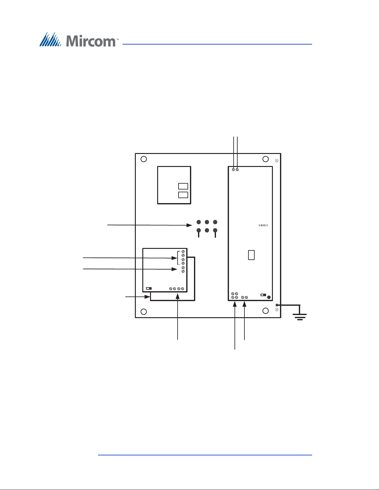
Touch Screen System and Setup
• Telephone Access Controller
• PC Sub Compact Board
• Power Supply Board
• Audio Mixer Board
To access the panel, remove the two screws and swing open the Touch Screen
panel.
Telephone Line
PC Sub Compact Board
Power
Terminals
(not polarity sensitive)
Microphone and
Speaker Connections
from Telephone
Access Controller
Microphone
Connection
from Touch
Screen
Power Supply Board
Figure 63. Controller Board Panel for 15” Touch Screens
Intranet
USB
Audio Mixer Board
On/Off
Speaker
Connections
Blk Wht
Microphone
and Speaker
Connections
to Audio Mixer
Telephone
Access
Controller
USB
Postal Lock
Input 1
SW1
On/Off
Chassis
Ground
3.2.3 Grounding
Grounding reduces the risk of electrical shock by providing an alternate escape
route for the electrical current. Touch Screen is equipped with a 16 gauge
electrical wire attached to the panel chassis ground post as shown in Figure 63.
To ground the Touch Screen attach one end of the supplied cable to a suitable
grounding wire and connect it to the site ground.
72 (126) TX3 Touch Screen Installation Manual Version 4.2
LT-996 Copyright 2017
Page 73
Touch Screen System and Setup
3.3 TX3-TOUCH-F15-B and TX3-TOUCH-S15-B Inside Door, Boards, and Grounding
3.3.1 Inside Door
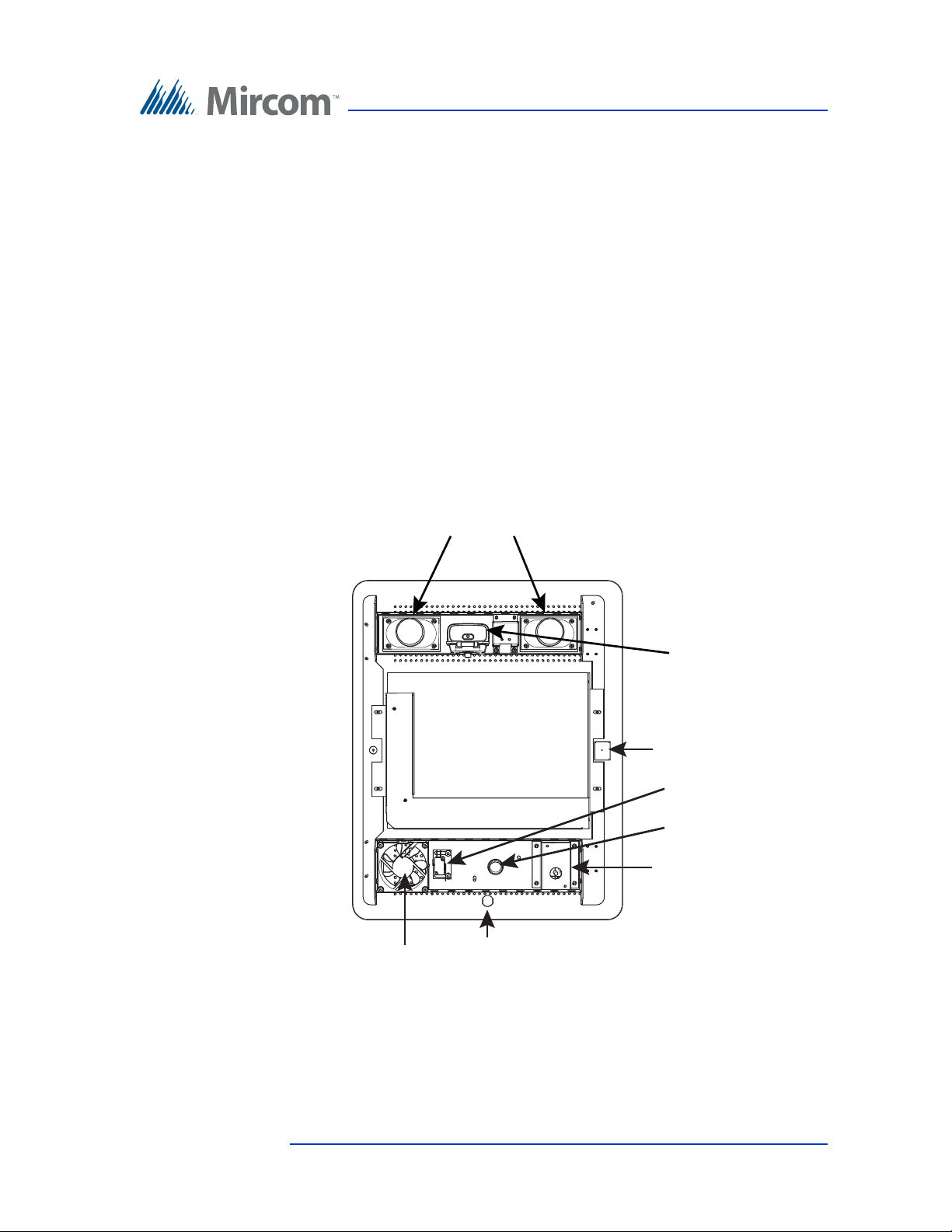
The inside doors of TX3-TOUCH-F15-B and TX3-TOUCH-S15-B contain the
following components as shown in Figure 64:
• Speakers
• Camera
•Postal Lock (optional)
•Fan (optional)
• Microphone
• P300 Card Reader
• Keyhole
Speakers
Camera
Microphone
Postal
Lock Switch
Postal
Lock
P300 Card Reader
Fan
Keyhole
Figure 64. TX3-TOUCH-F15-B and TX3-TOUCH-S15-B Inside Door
Version 4.2 TX3 Touch Screen Installation Manual 73 (126)
LT-996 Copyright 2017
Page 74
3.3.2 Controller Boards
USB Port for
Keyboard
On/Off Switch
Telephone Line
Telephone
Access
Controller
USB
Intranet
Power Supply and
Audio Mixer Board
On/Off
USB
PC Sub Compact
Board
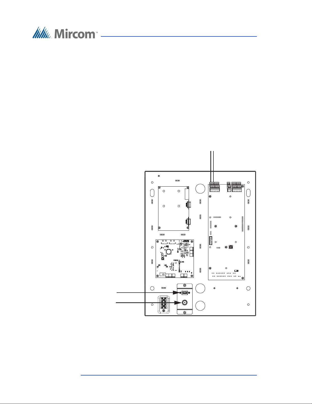
The TX3-TOUCH-F15-B and TX3-TOUCH-S15-B contain the following
components and controller boards as shown in Figure 65:
• On/Off Switch
•USB Port
• Telephone Access Controller
• PC Sub Compact Board
• Power Supply and Audio Mixer Board
To access the panel, unlock the door and swing it open.
Touch Screen System and Setup
74 (126) TX3 Touch Screen Installation Manual Version 4.2
LT-996 Copyright 2017
Figure 65. Controller Board Panel for TX3-TOUCH-F15-B and
TX3-TOUCH-S15-B
Page 75
3.3.3 Grounding
USB
On/Off Switch
Telephone
Access
Controller
Power Supply and
Audio Mixer Board
On/Off
PC Sub Compact
Board
Ground
Screw
16 Gauge
Wire to
Ground
Power
Terminals
+
-
16 Gauge Wire 16 Gauge Wire
to Groundto Ground
Ground Ground
ScrewScrew
Power
Terminals
+
-
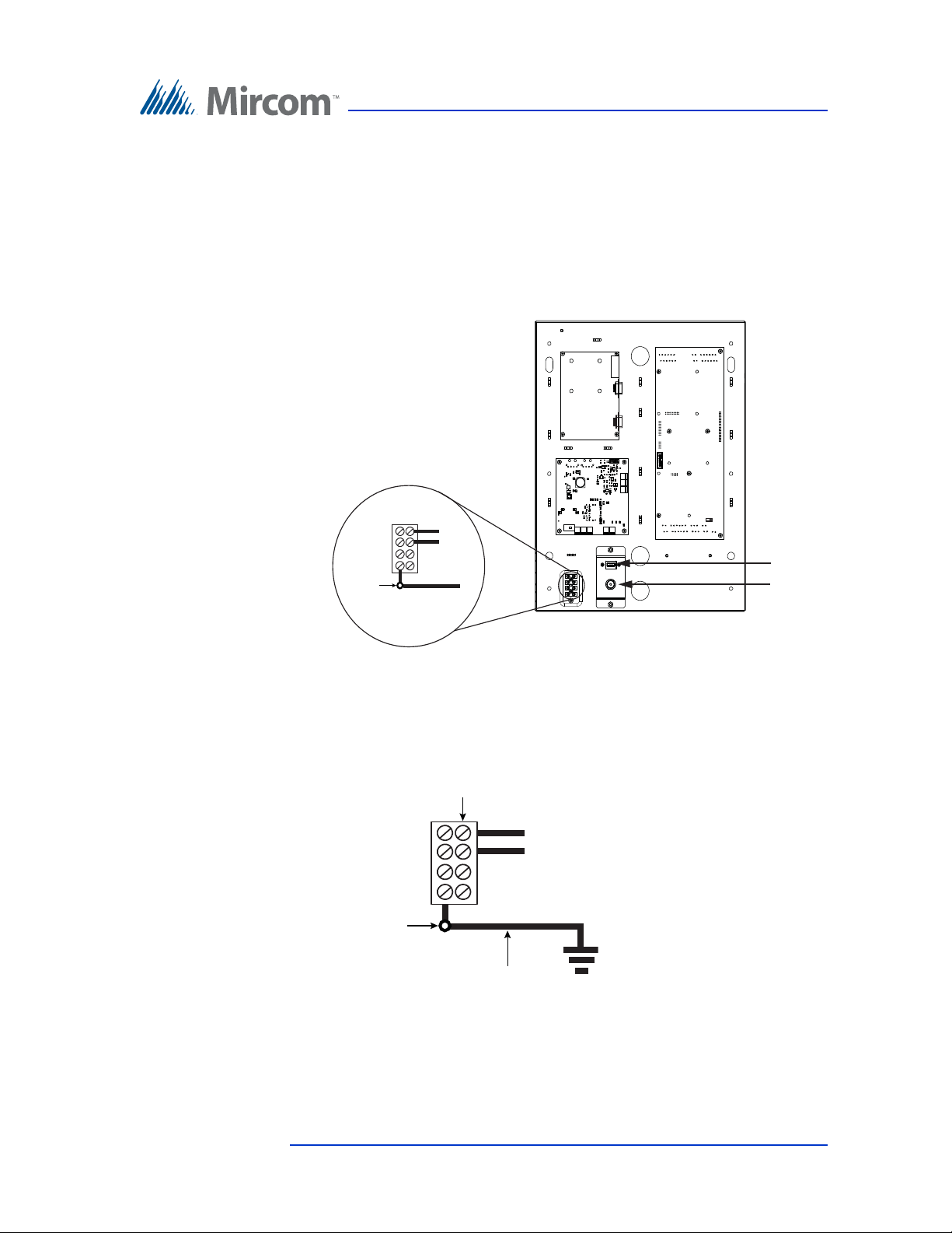
Grounding reduces the risk of electrical shock by providing an alternate escape
route for the electrical current.
To ground TX3-TOUCH-F15-B and TX3-TOUCH-S15-B
1. The ground terminal is shown in Figure 66.
Touch Screen System and Setup
Figure 66. Ground and power terminals
2. Attach the ground screw to a suitable grounding wire and connect it to the
site ground, as shown in Figure 67.
Figure 67. Grounding TX3-TOUCH-F15-B and TX3-TOUCH-S15-B
Version 4.2 TX3 Touch Screen Installation Manual 75 (126)
LT-996 Copyright 2017
Page 76

Touch Screen System and Setup
3.4 TX3-TOUCH-F22 and TX3-TOUCH-S22 Inside Door, Boards, and Grounding
The 22” Touch Screen inside doors contain the following components as shown
in Figure 68:
•Speakers
• Camera
•Postal Lock (optional)
•Fan (optional)
• Microphone
• P300 Card Reader
• Keyhole
76 (126) TX3 Touch Screen Installation Manual Version 4.2
LT-996 Copyright 2017
Page 77
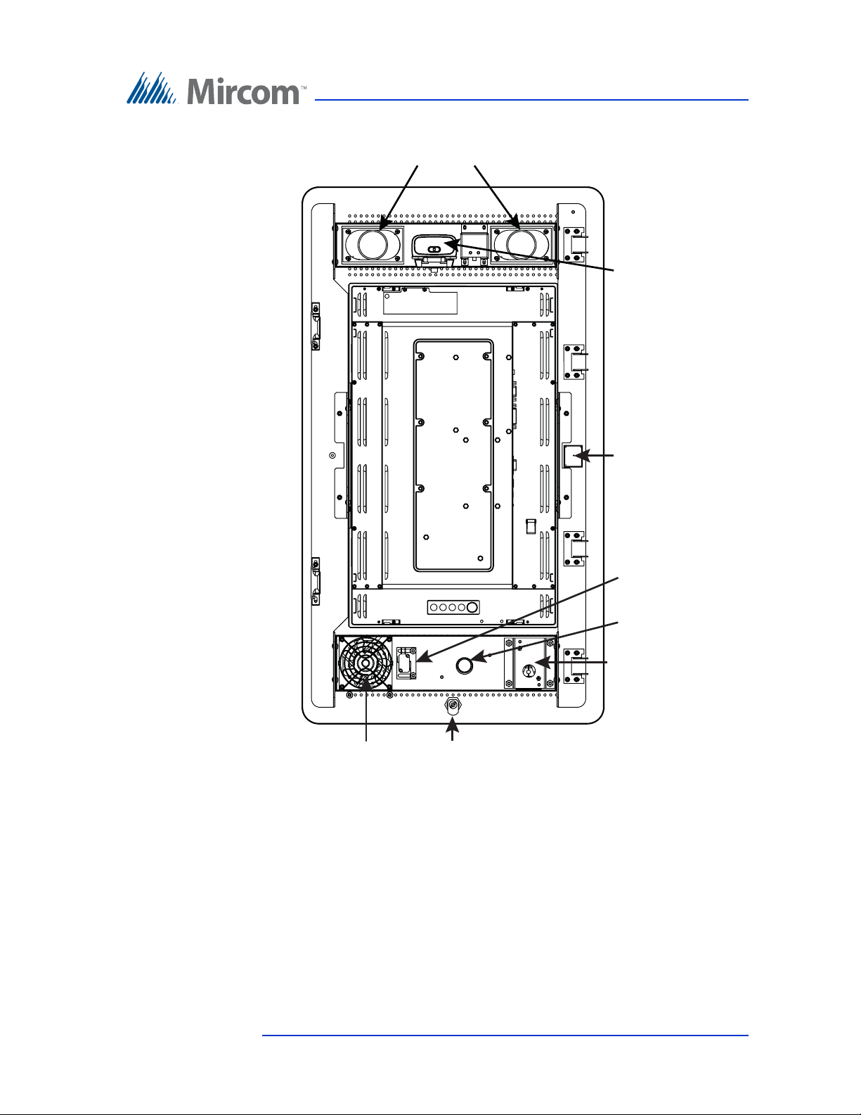
Speakers
Touch Screen System and Setup
Camera
Microphone
Fan
Figure 68. TX3-TOUCH-F22 and TX3-TOUCH-S22 Inside Door
3.4.1 Controller Boards
The 22” Touch Screen Panel contains the following components and controller
boards as shown in Figure 69:
•On/Off Switch
•USB Port
• Telephone Access Controller
Postal
Lock Switch
Postal
Lock
P300 Card Reader
Keyhole
• PC Sub Compact Board
Version 4.2 TX3 Touch Screen Installation Manual 77 (126)
LT-996 Copyright 2017
Page 78
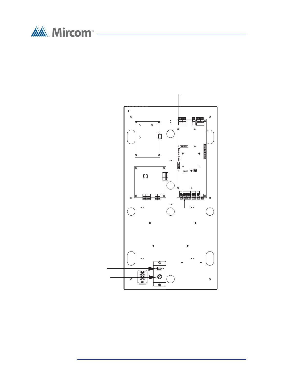
Touch Screen System and Setup
USB Port for
Keyboard
On/Off Switch
PC Sub Compact
Board
Telephone
Access
Controller
Telephone Line
USB
Intranet
Power Supply and
Audio Mixer Board
Postal Lock
On/Off
USB
• Power Supply and Audio Mixer Board
To access the panel, unlock the door and swing it open.
To access the power and ground terminals, remove the nut and open the cover at
the bottom of the unit as shown in Figure 69.
3.4.2 Grounding
Figure 69. Controller Board Panel for TX3-TOUCH-F22 and TX3-
TOUCH-S22
Grounding reduces the risk of electrical shock by providing an alternate escape
route for the electrical current.
78 (126) TX3 Touch Screen Installation Manual Version 4.2
LT-996 Copyright 2017
Page 79
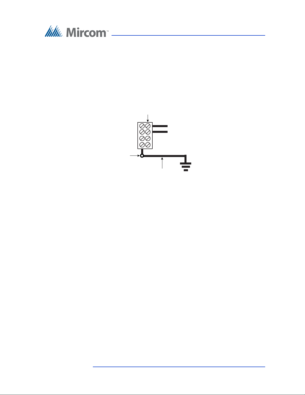
Touch Screen System and Setup
16 Gauge Wire
to Ground
Ground
Screw
To ground the 22” Touch Screen
1. Remove the nut and open the cover at the bottom of the unit as shown in
Figure 69.
2. Attach the ground screw to a suitable grounding wire and connect it to the
site ground, as shown in Figure 70.
Power
Terminals
(not polarity sensitive)
Ground
Screw
16 Gauge Wire
to Ground
Figure 70. Grounding the 22” Touch Screen
Version 4.2 TX3 Touch Screen Installation Manual 79 (126)
LT-996 Copyright 2017
Page 80
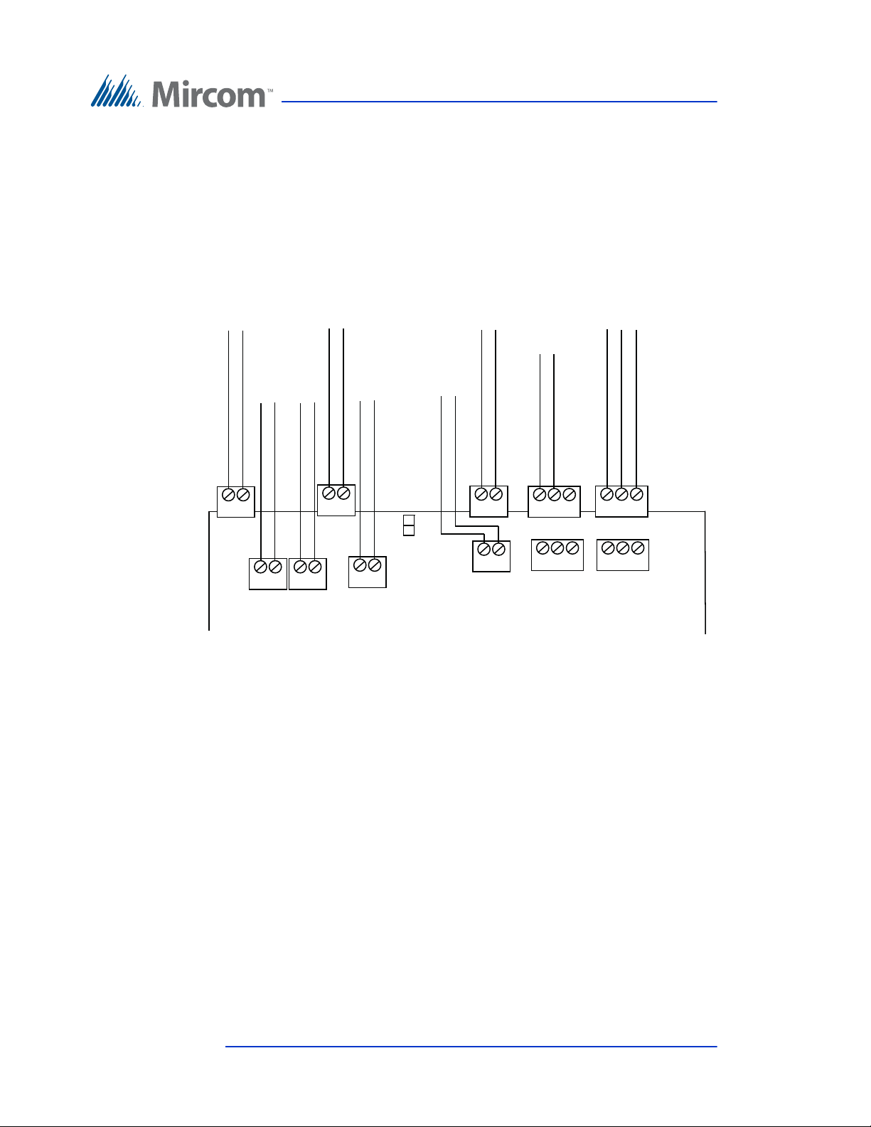
Touch Screen System and Setup
Telephone Lines 1 to 5
Line 1
T R
Line 2
T R
Line 3
T R
Line 5
T R
Line 4
T R
AC
Door Strike
AC or DC
Input Door
Strike Supply
DC Output 1
Door Strike
Aux. Door
Output 2
Relay
General Relay
Output 4
NO NC C
NO NC C
General Relay
Output 3
JW8
3.5 Telephone Access Controller Board
For detailed information about the Telephone Access Controller installation and
setup see LT-969 TX3-Telephone Access System Installation and Operation
Manual.
Figure 71 shows the connectors at the top of the Telephone Access controller.
Figure 71. Controller Board Connectors - Top
80 (126) TX3 Touch Screen Installation Manual Version 4.2
LT-996 Copyright 2017
Page 81
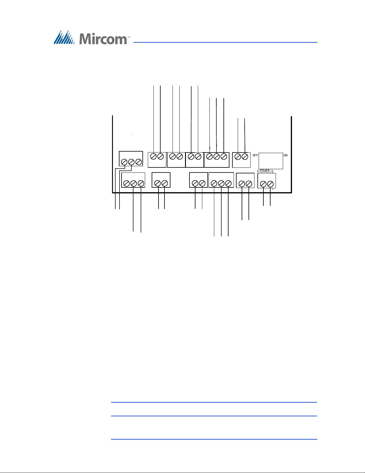
Touch Screen System and Setup
LED/LAMP
Supply
Speaker
Input 1
Input 2 Input 3 Input 4
Input 5
Camera Supply
Power Supply for TX3
(use 18 AWG)
RS-485 OUT
- +
- +
- s +
RS-485 IN
- s +
- +
- +
+--++-
+-
+Microphone
Connection
Figure 72 shows the connectors at the bottom of the Telephone Access controller.
Figure 72. Controller Board Connectors - Bottom
3.6 Connecting to the External Power Supply
The power supply terminal block is shown in Figures 63, 66, and 69. It receives
24 VDC from the external MD-990 power supply.
The external MD-990 power supply connects to the building power AC power
supply. A voltage selectable switch is located on the side of the unit and is factory
set to 120 V.
For best operation install the external power supply into its own dedicated
electrical outlet to protect it from excessive power surges and current
fluctuations.
All Touch Screen controller boards use the MD-990 for their power supply. The
door strike power supply depends on the door strike power requirements.
Note: Install the power supply outside the Touch Screen enclosure.
Version 4.2 TX3 Touch Screen Installation Manual 81 (126)
LT-996 Copyright 2017
Page 82
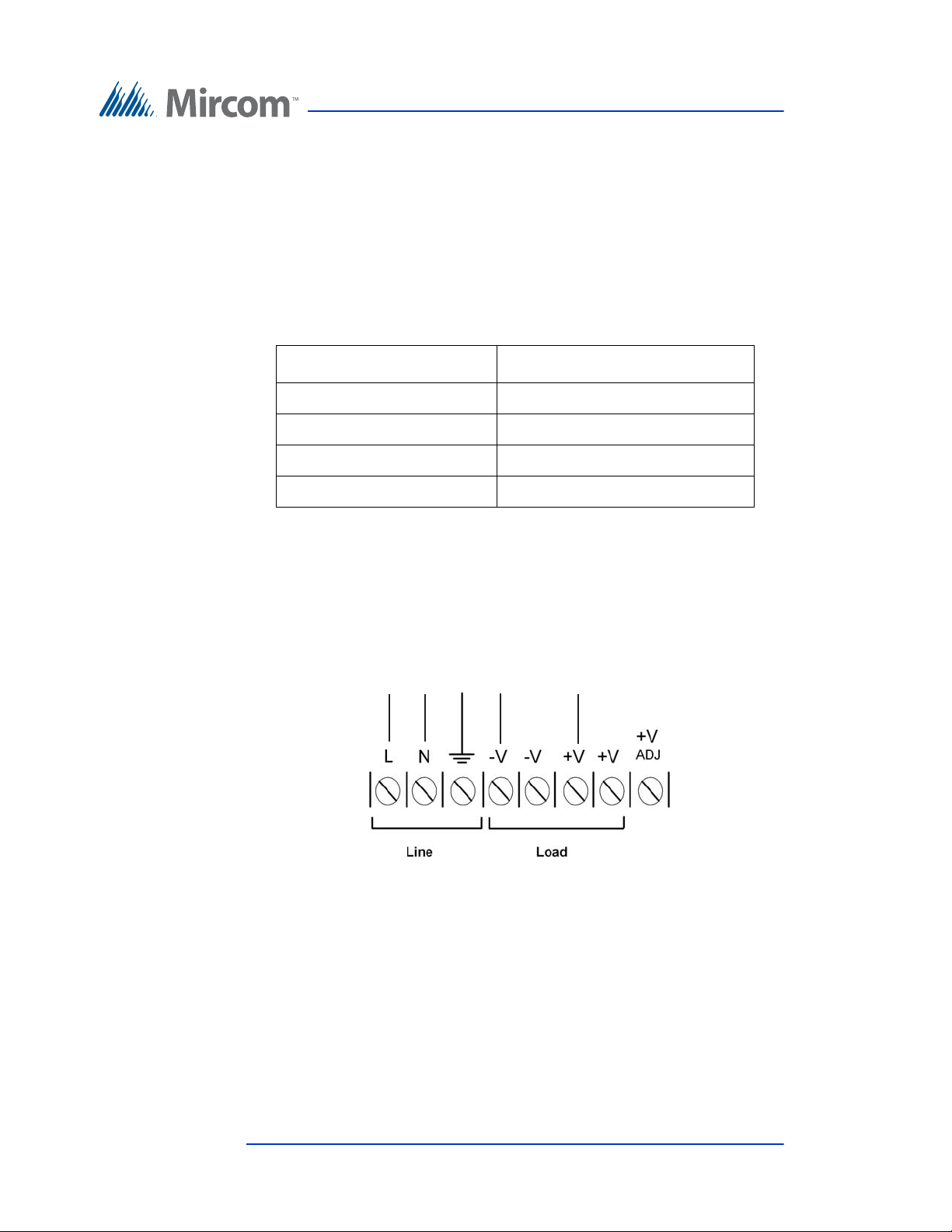
3.6.1 Maximum Power Supply Wire Distances
To building
power
To Touch Screen
{
{
The distance from the Touch screen to the power supply is a function of the wire
gauge and the resistance generated by the cable by the power draw.
Do not exceed the maximum distances from the Touch screen to the power
supply as indicated in Table 1.
Table 1: Maximum Power Supply Wire Distances
Gauge Distance
16 125 ft (38.1 m)
14 200 ft (60.96 m)
12 320 ft (97.536 m)
10 500 ft (152.4 m)
Touch Screen System and Setup
3.6.2 Wiring the External Power Supply
The power supply terminals are located at the bottom of the MD-990 external
power supply as shown in Figure 73.
Figure 73. MD-990 Terminal Block Wiring
To connect the power supply
1. Turn the power off from the Touch Screen Panel.
2. Mount the MD-990 power supply separately from the Touch Screen.
82 (126) TX3 Touch Screen Installation Manual Version 4.2
LT-996 Copyright 2017
3. Ensure the MD-990 voltage selectable switch is set to 120V. See Installing
the Power Supply Enclosure on page 63.
Page 83

Touch Screen System and Setup
4. Connect the MD-990 load power supply wires to the Touch Screen
Controller board panel terminal screws as shown in Figures 63, 67, and 69.
5. Connect the building power supply wires to the MD-990 line terminal
screws as shown in Figure 73.
6. Connect the other end of the building power supply wires the line voltage
terminals.
7. Turn the power on.
3.7 Turning the Touch Screen On and Off
Note: Never turn off power when the system is operational.
To shut down the Touch Screen
1. At the Touch Screen terminal, enter 9999.
2. Enter your administrator password, and then press OK.
3. Select File > Shut down > Shut down.
4. Do not disconnect the power until the full shut down process has been
completed.
To turn on the Touch Screen
1. Press the power switch.
On TX3-TOUCH-K15-A, TX3-TOUCH-F15-A, TX3-TOUCH-S15-A, the
power switch is on the outside of the door (Figure 62).
On TX3-TOUCH-F15-B, TX3-TOUCH-S15-B, TX-TOUCH-F22, TX3TOUCH-S22, the power switch is above the USB port (Figure 66 and Figure 69).
Version 4.2 TX3 Touch Screen Installation Manual 83 (126)
LT-996 Copyright 2017
Page 84

3.8 Installing the Postal Lock
The system has a built-in micro switch and mounting hardware for a postal lock
installation. If postal service is required, contact the Post Office to obtain the
lock.
Note: When installing the postal lock leave the micro switch tie wrap in
place. Remove the tie wrap after the postal lock is installed.
Input 1 on the Telephone Access Controller connects to the Postal Lock microswitch.
3.9 Installing the Telephone Lines
Telephone lines 1 to 5 are situated at the top left of the main controller board as
shown in Figure 71. Both NSL and ADC lines can be connected. Each T/R line is
polarity insensitive and can be reversed.
Touch Screen System and Setup
3.10 Installing Optional Components
The optional components consist of the following:
USB keyboard and mouse. The USB connector allows you the use of these
controls at the Touch Screen for configuration purposes.
Internet/LAN. The Internet/LAN connector allows you to connect the Touch
Screen to the building LAN.
Replacement telephone access controller board. For details on the telephone
access controller board, see LT-6073 Telephone Access Quick Reference.
Camera. For instructions on installing an IP camera, see section 3.15 on
page 102.
Replacement 22” display. For instructions on installing a replacement 3M
Multi-Touch Display, see section 3.16 on page 104.
Fan. For instructions on installing a fan in the 22” Touch Screen, see LT-6074
Installing the Fan in the 22” Touch Screen.
Two door controller network board. For instructions on installing a two door
controller network board, see LT-981A Replacement TX3-CX-2-A Controller
Board Installation Instructions.
84 (126) TX3 Touch Screen Installation Manual Version 4.2
LT-996 Copyright 2017
Page 85
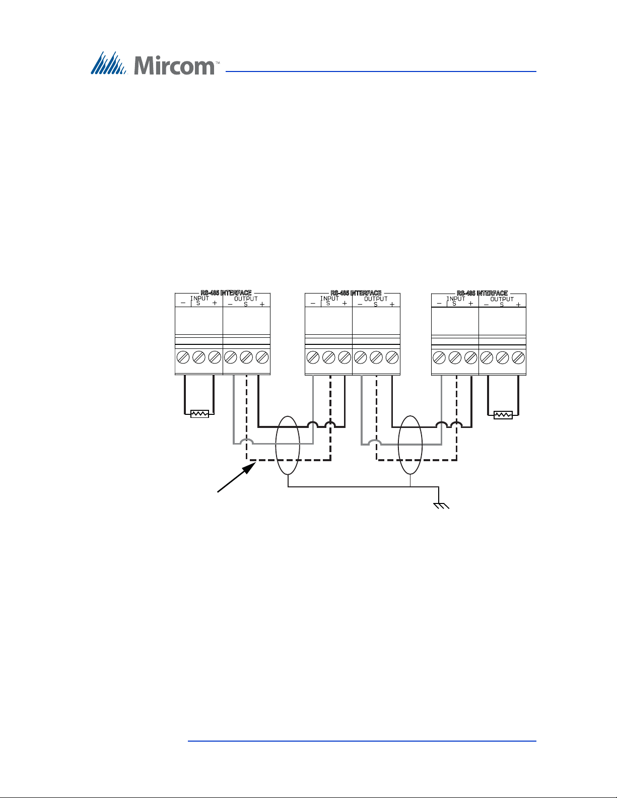
Touch Screen System and Setup
k
RS-485. An RS-485 terminal lets you easily connect multiple Touch Screen and
telephone and card access controllers across a network. The RS-485 terminal
consists of + (positive), - (negative), and S (Shield) connections. See Figure 74.
22 AWG twisted pair, maximum length: 4000 feet (1219.2 m)
Mircom recommends shielded cable
There are two additional RS-485 Terminal Connectors that must be added to the
FIRST and LAST node of the network. On the FIRST node of the network attach
the connector to the RS-484 IN. One the LAST node of the network attach the
terminal connector to the RS-485 OUT. See Figure 74.
Panel 1
First panel on network
120 Ω
Optional common
reference connection
if available
Figure 74. Connecting additional RS-485 Terminal Connector to
the First or Last Node of Network
Panel 2
Panel 3
Last panel on networ
Connect shield to chassis
ground on one panel only
120 Ω
USB Port. The USB port provides a connection to a PC, for configuring the card
access system and down loading any new firmware.
Version 4.2 TX3 Touch Screen Installation Manual 85 (126)
LT-996 Copyright 2017
Page 86
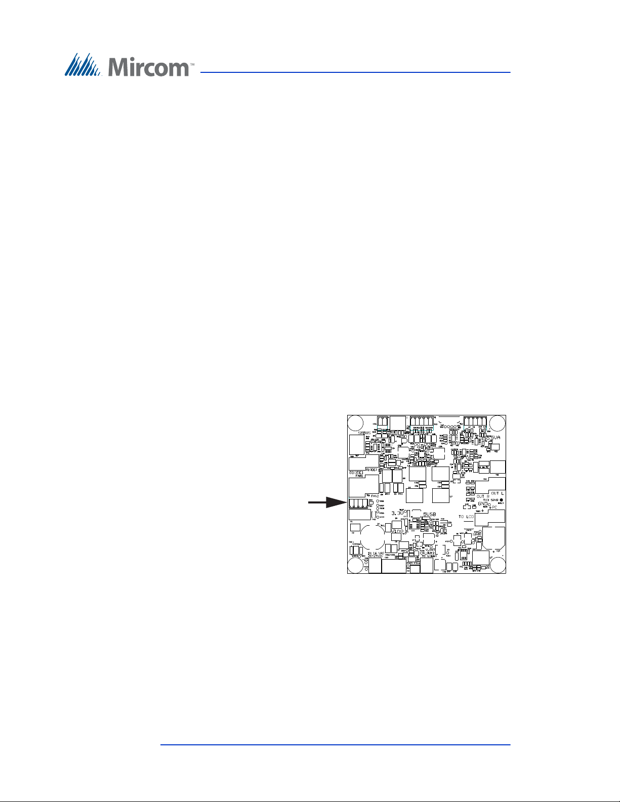
3.11 Verifying Installed Components
On MD-1236 the button
connector is on the left
Before turning on the system it is important to verify that the following
connections are firmly in place.
For additional information about the Telephone Access Controller Board
Connectors see LT-969 TX3-Telephone Access System Installation and
Operation Manual.
Factory wiring is different depending on which model of the power supply and
audio mixer board is in the Touch Screen unit.
To tell the difference between models of power supply and audio
mixer boards
On MD-1236:
• The 4-terminal button connector is labeled TS11 and is on the left
side.
• There is a yellow label on the board that says MD-1236.
Touch Screen System and Setup
On MD-1105:
• The 4-terminal button connector is labeled TS7 and is on the top.
• There is a yellow label on the board that says MD-1105.
Figure 75. MD-1236
86 (126) TX3 Touch Screen Installation Manual Version 4.2
LT-996 Copyright 2017
Page 87
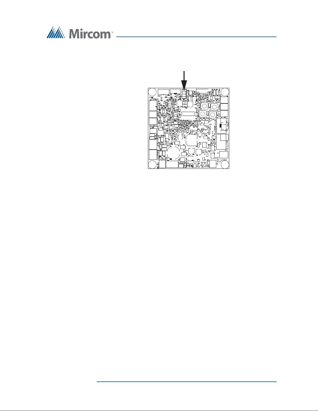
Figure 76. MD-1105
On MD-1105 the button
connector is on the top
Touch Screen System and Setup
• If you have MD-1236, refer to section 3.12 on page 88.
• If you have MD-1105, refer to section 3.13 on page 95.
Version 4.2 TX3 Touch Screen Installation Manual 87 (126)
LT-996 Copyright 2017
Page 88
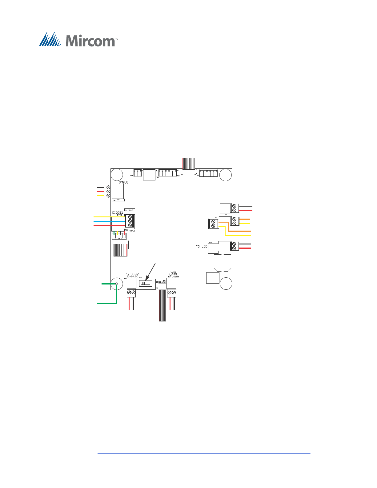
Touch Screen System and Setup
WX-081: CN1 on PC board
WX-079: CN31 on PC board
WX-109: TS2 on telephone
access controller
WR-21160 and WR-21162:
Power (CN6)
on PC board
+
-
WX-110: TS4 (bottom)
on telephone access
controller
WR-12223 and WR-12224:
Left Speaker
WR-12223 and WR-12224:
Right Speaker
WX-080: CN2
on PC board
P3
P1
TS1
TS4A
TS12
P2
TS9
SW-207: Button
WR-21160 and
WR-21162: Power
terminals
TS11
SW3 on the LEFT
TS10A
TS4B
TS7
WX-520: CN4
on PC board
only if fan is
present
TS6A
Fan (if present)
+
-
WX-070:
Ground wire to
chassis ground
WX-070: Ground
wire to telephone
access controller
-
+
+
-
+
-
-
+
Black (ground)
White (data)
Red (clock)
YY
B
R
3.12 Factory Wiring for Touch Screen Units with MD-1236
Sections 3.12.1 and 3.12.2 show the wiring for Touch Screen units with model
MD-1236 of the power supply and audio mixer board.
The diagrams include the Mircom part numbers of the cables (they begin with
WX or WR).
3.12.1 Factory Wiring for TX3-TOUCH-S15-B and TX3-TOUCH-F15-B with MD-1236
88 (126) TX3 Touch Screen Installation Manual Version 4.2
LT-996 Copyright 2017
Figure 77. Factory connections on MD-1236 for TX3-TOUCH-S15-B
and TX3-TOUCH-F15-B
Page 89
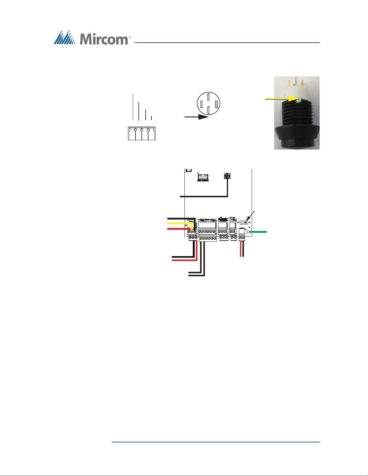
Figure 78. Wiring the Button
4
TS11 on
MD-1236
321
Button (bottom view)
Notch
Notch
Button (side view)
black
white
red
green
green
black
white
red
WX-110: TS1 on
MD-1236
TS4
WX-109: TS12
on MD-1236
TS2
WX-077:
Microphone
JP1
WX-053: USB on
PC board
WX-030: Postal
lock switch
(optional)
TS5
TS2
Power switch
+
-
WX-070:
Ground wire
to MD-1236
+
-
B
W
R
Touch Screen System and Setup
Figure 79. Factory connections on the telephone access controller
board for TX3-TOUCH-S15-B and TX3-TOUCH-F15-B
with MD-1236
Version 4.2 TX3 Touch Screen Installation Manual 89 (126)
LT-996 Copyright 2017
Page 90
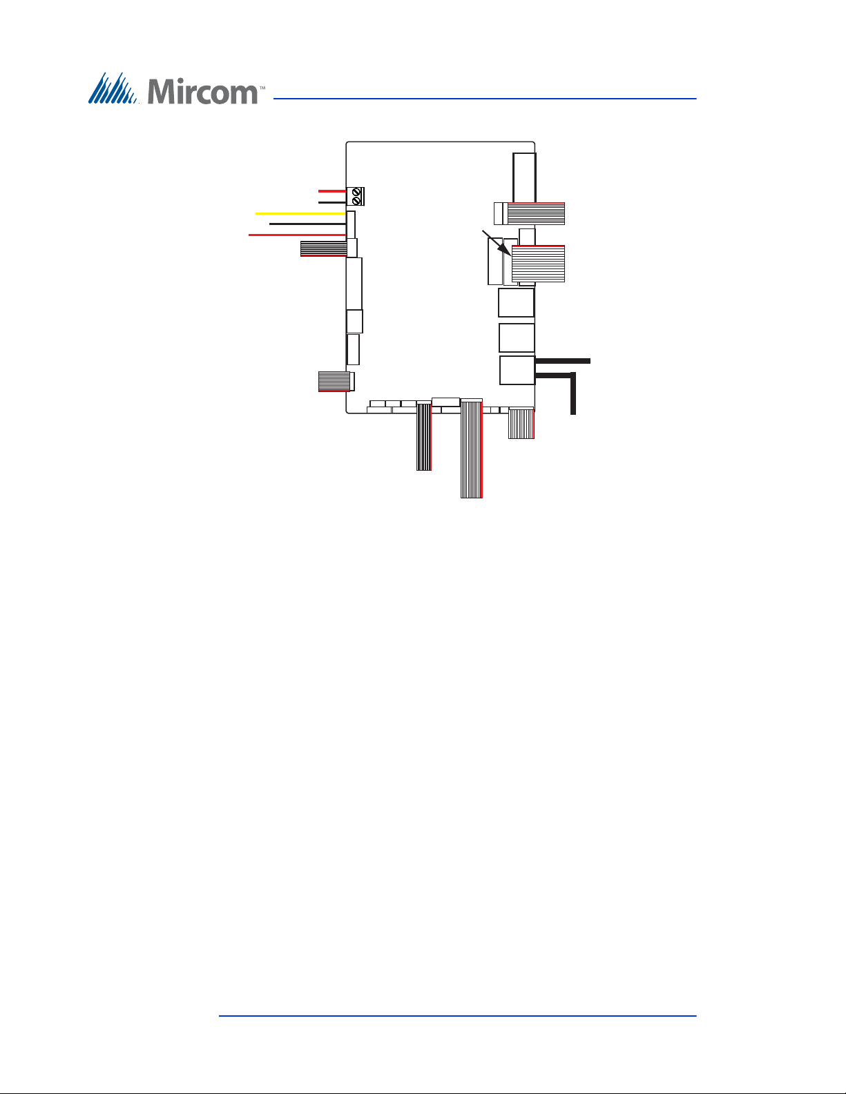
Touch Screen System and Setup
WR-21160 and
WR-21162: TS10A on
audio mixer
+
-
CN6
CN2
WX-081: P3 on
MD-1236
CN1
WX-079: P1 on
MD-1236
CN31
WX-057:
Touch screen
CN20
CN15
WX-089:
USB extension
WX-055:
Touch screen display
CN27
CN26
WX-054:
Touch screen display
WX-053: JP1 on
controller
Camera
USB
WX-520: TS7 on
MD-1236 only if
fan is present
NOTE: Use only
the top 3 pins
CN4
Black (ground)
White (data)
Red (clock)
WX-080: P2 on
MD-1236
telephone access
display
Figure 80. Factory connections on the PC sub compact board for
TX3-TOUCH-S15-B and TX3-TOUCH-F15-B for MD-1236
90 (126) TX3 Touch Screen Installation Manual Version 4.2
LT-996 Copyright 2017
Page 91
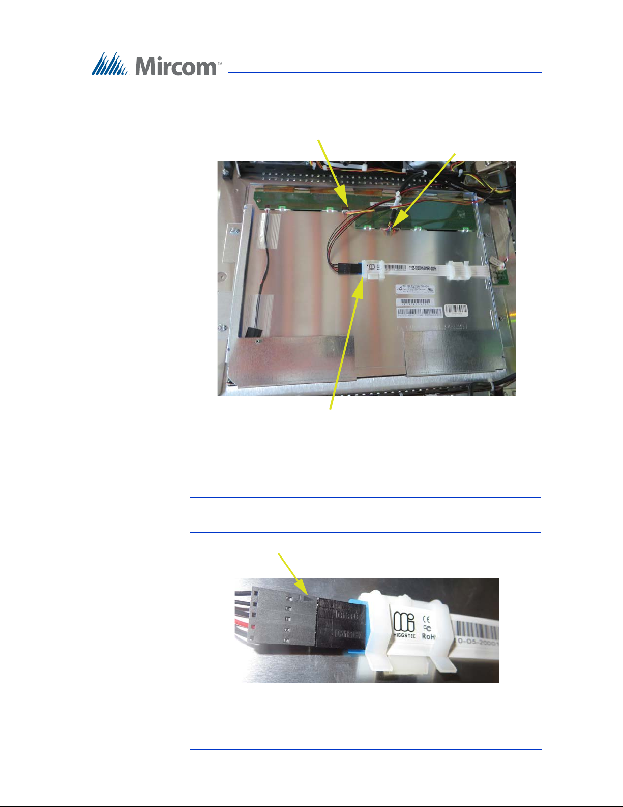
Touch Screen System and Setup
WX-055: CN27
on PC sub
compact board
WX-054: CN26 on PC
sub compact board
WX-057: CN20 on PC
sub compact board
Arrow
Figure 81. Display connections on TX3-TOUCH-S15-B and TX3-
TOUCH-F15-B for MD-1236
Attention: The bottom cable must be connected so that the arrow is on the
outside.
Figure 82. Make sure that the arrow is visible
Version 4.2 TX3 Touch Screen Installation Manual 91 (126)
LT-996 Copyright 2017
Page 92
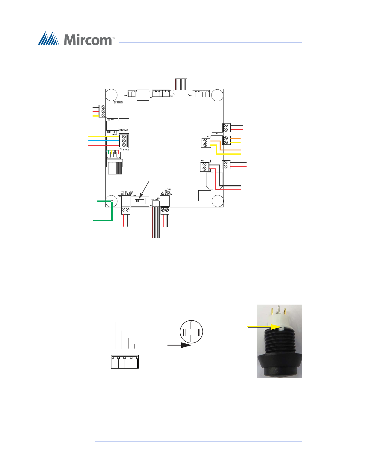
Touch Screen System and Setup
+
-
P3
P1
TS1
TS4A
TS12
P2
TS9
SW3 on the LEFT
SW3
TS4B
MD-1256: Power on
22 inch display
+
-
TS10B
TS10A
TS7
TS11
TS6A
+
-
WX-079: CN31 on PC board
WX-520: CN4
on PC board
only if fan is
present
Black (ground)
White (data)
Red (clock)
Fan (if present)
YY
B
R
SW-207: Button
WX-081: CN1 on PC board
WX-070:
Ground wire to
chassis ground
WX-070: Ground
wire to telephone
access controller
WX-080: CN2
on PC board
WX-109: TS2 on telephone
access controller
+
-
WR-21160 and WR-21162:
Power (CN6)
on PC board
WR-12223 and WR-12224:
Left Speaker
WR-12223 and WR-12224:
Right Speaker
-
+
+
WX-110: TS4 (bottom)
on telephone access
controller
WR-21160 and
WR-21162: Power
terminals
+
-
4
TS11 on
MD-1236
321
Button (bottom view)
Notch
Notch
Button (side view)
black
white
red
green
green
black
white
red
3.12.2 Factory Wiring for TX3-TOUCH-S22 and TX3-TOUCH-F22 with MD-1236
Figure 83. Factory connections on the power supply and audio
mixer board (MD-1236) for TX3-TOUCH-S22 and TX3TOUCH-F22
92 (126) TX3 Touch Screen Installation Manual Version 4.2
LT-996 Copyright 2017
Figure 84. Wiring the button
Page 93
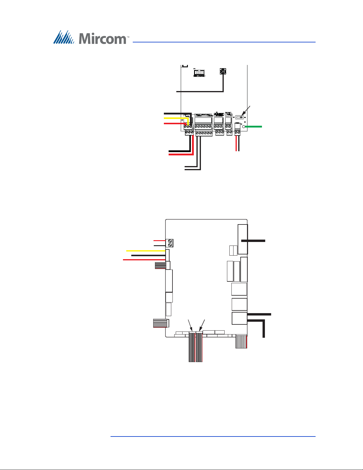
Touch Screen System and Setup
WX-110: TS1 on
MD-1236
TS4
WX-109: TS12
on MD-1236
TS2
WX-077:
Microphone
JP1
WX-053: USB on
PC board
WX-030: Postal
lock switch
(optional)
TS5
TS2
Power switch
+
-
WX-070:
Ground wire
to MD-1236
+
-
B
W
R
CN6
CN2
CN1
CN31
CN15
CN32
Camera
USB
Touch Screen VGA
cable
CN14
CN4
WR-21160 and
WR-21162: TS10A on
MD-1236
+
-
WX-520: TS7 on
MD-1236 only if
fan is present
NOTE: Use only
the top 3 pins
Black (ground)
White (data)
Red (clock)
WX-080: P2 on
MD-1236
WX-081: P3 on
MD-1236
WX-082:
USB to display
WX-089:
USB extension
WX-079: P1 on
MD-1236
WX-053: JP1 on
telephone access
controller
Figure 85. Factory connections on the telephone access controller
board for TX3-TOUCH-S22 and TX3-TOUCH-F22 for MD1236
Figure 86. Factory connections on the PC sub compact board for
TX3-TOUCH-S22 and TX3-TOUCH-F22 for MD-1236
Version 4.2 TX3 Touch Screen Installation Manual 93 (126)
LT-996 Copyright 2017
Page 94
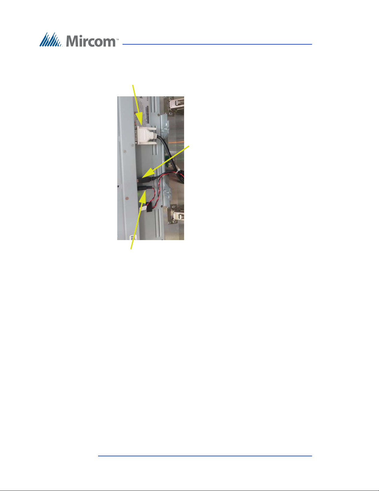
Touch Screen System and Setup
WX-082: USB
extension on PC
sub compact
board
CN32 on PC sub
compact board
MD-1256: TS10B on
MD-1236
Figure 87. Display connections on TX3-TOUCH-S22 and TX3-
TOUCH-F22 for MD-1236
94 (126) TX3 Touch Screen Installation Manual Version 4.2
LT-996 Copyright 2017
Page 95
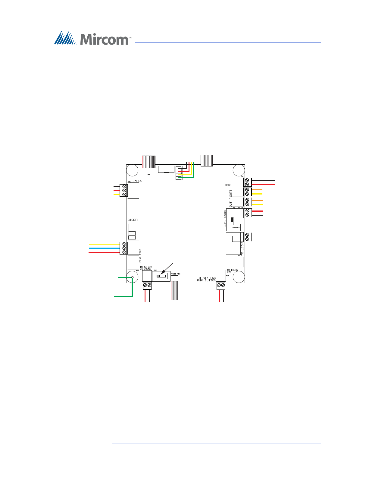
Touch Screen System and Setup
+
-
P5 P1
TS1
TS2
TS3
TS4
TS8
P4
TS5
SW-207: Button
TS7
SW3 on the LEFT
SW3
WX-079: CN31 on PC board
WX-081: CN1 on PC board
WR-21160 and
WR-21162: Power
terminals
+
-
WX-080: CN2
on PC board
WX-109: TS2 on telephone
access controller
+
-
WR-21160 and WR-21162:
Power (CN6)
on PC board
WR-12223 and WR-12224:
Left Speaker
WR-12223 and WR-12224:
Right Speaker
-
+
-
+
WX-110: TS4 (bottom)
on telephone access
controller
+
-
WX-520: CN4
on PC board
only if fan is
present
Black (ground)
White (data)
Red (clock)
Fan (if present)
YY
B
R
WX-070:
Ground wire to
chassis ground
WX-070: Ground
wire to telephone
access controller
TS11
3.13 Factory Wiring for Touch Screen Units with MD-1105
Sections 3.13.1 and 3.13.2 show the wiring for Touch Screen units with model
MD-1105 of the power supply and audio mixer board.
The diagrams include the Mircom part numbers of the cables (they begin with
WX or WR).
3.13.1 Factory Wiring for TX3-TOUCH-S15-B and TX3-TOUCH-F15-B with MD-1105
Version 4.2 TX3 Touch Screen Installation Manual 95 (126)
LT-996 Copyright 2017
Figure 88. Factory connections on the power supply and audio
mixer board (MD-1105) for TX3-TOUCH-S15-B and TX3TOUCH-F15-B
Page 96
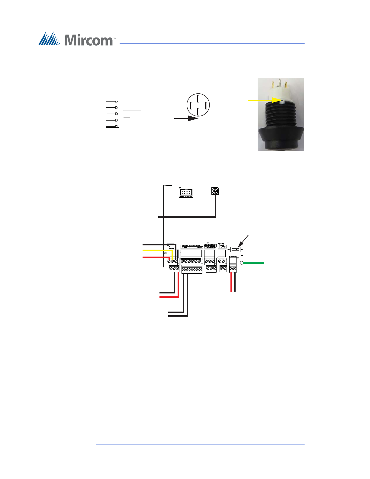
Figure 89. Wiring the button
green
1
black
white
red
TS7 on
MD-1105
2
3
4
Button (bottom view)
Notch
Notch
Button (side view)
green
white
red
black
TS4
JP1
Postal lock switch
(optional)
TS5
TS2
Power switch ON
WX-053: USB on
PC board
WX-110: TS1 on
MD-1105
+
WX-109: TS8 on
MD-1105
+
-
WX-070:
Ground wire
to MD-1236
WX-077:
Microphone
B
W
R
Touch Screen System and Setup
Figure 90. Factory connections on the telephone access controller
board for TX3-TOUCH-S15-B and TX3-TOUCH-F15-B for
MD-1105
96 (126) TX3 Touch Screen Installation Manual Version 4.2
LT-996 Copyright 2017
Page 97
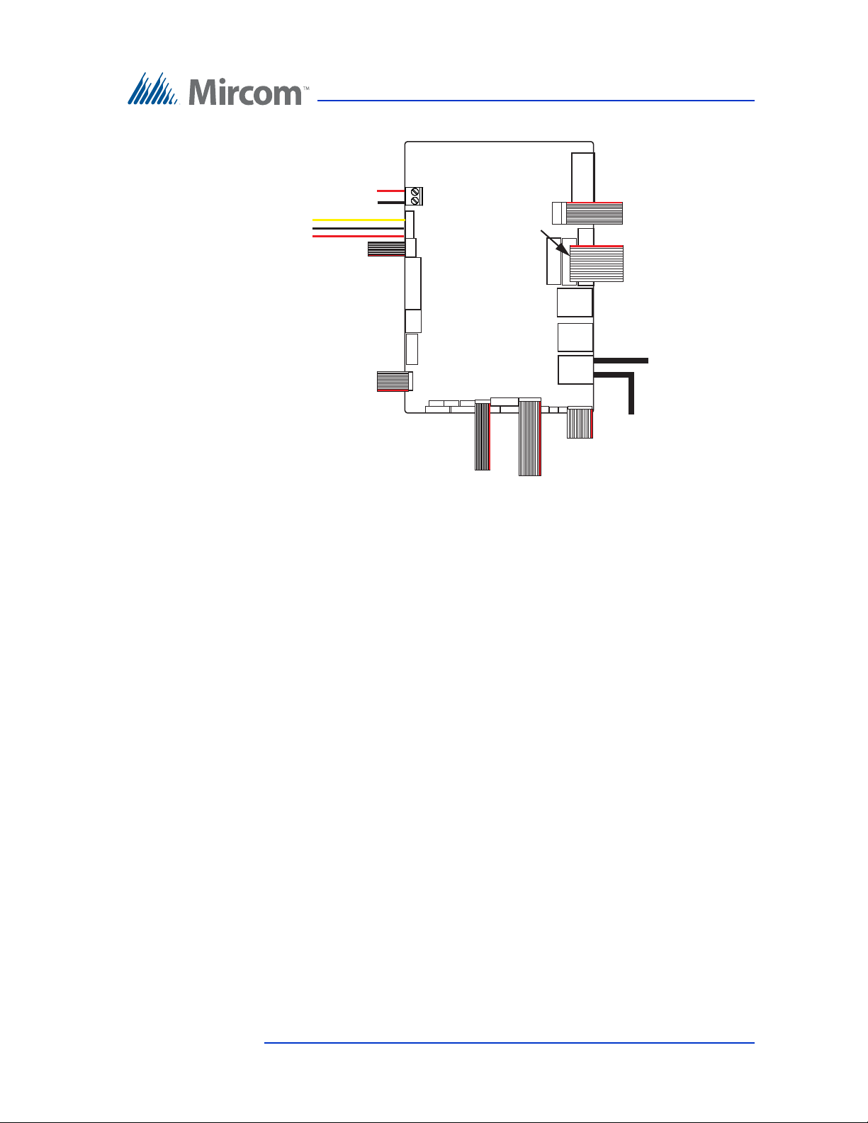
Touch Screen System and Setup
+
-
CN6
CN2
CN1
CN31
CN20
CN15
CN27
CN26
Camera
USB
WR-21160 and
WR-21162: TS4 on
MD-1105
WX-080: P4 on
MD-1105
WX-081: P5 on
MD-1105
WX-089:
USB extension
WX-057:
Touch screen
display
WX-079: P1 on
MD-1105
WX-053: JP1 on
telephone access
controller
WX-055:
Touch screen display
WX-054:
Touch screen display
WX-520: TS11 on
MD-1105 only if
fan is present
NOTE: Use only
the top 3 pins
Black (ground)
White (data)
Red (clock)
CN4
Figure 91. Factory connections on the PC sub compact board for
TX3-TOUCH-S15-B and TX3-TOUCH-F15-B for MD-1105
Version 4.2 TX3 Touch Screen Installation Manual 97 (126)
LT-996 Copyright 2017
Page 98
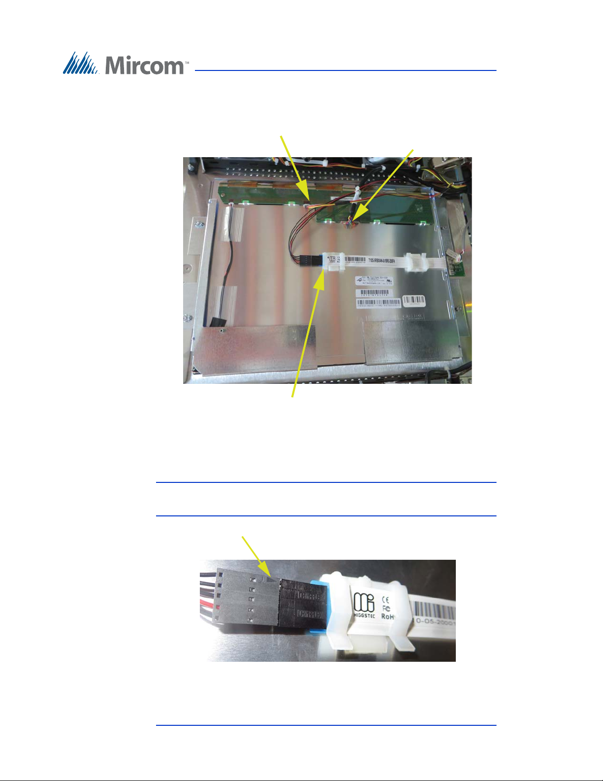
Touch Screen System and Setup
WX-054: CN26 on PC
sub compact board
WX-055: CN27
on PC sub
compact board
WX-057: CN20 on PC
sub compact board
Figure 92. Display connections on TX3-TOUCH-S15-B and TX3-
TOUCH-F15-B
Attention: The bottom cable must be connected so that the arrow is on the
outside.
Arrow
Figure 93. Make sure that the arrow is visible
98 (126) TX3 Touch Screen Installation Manual Version 4.2
LT-996 Copyright 2017
Page 99
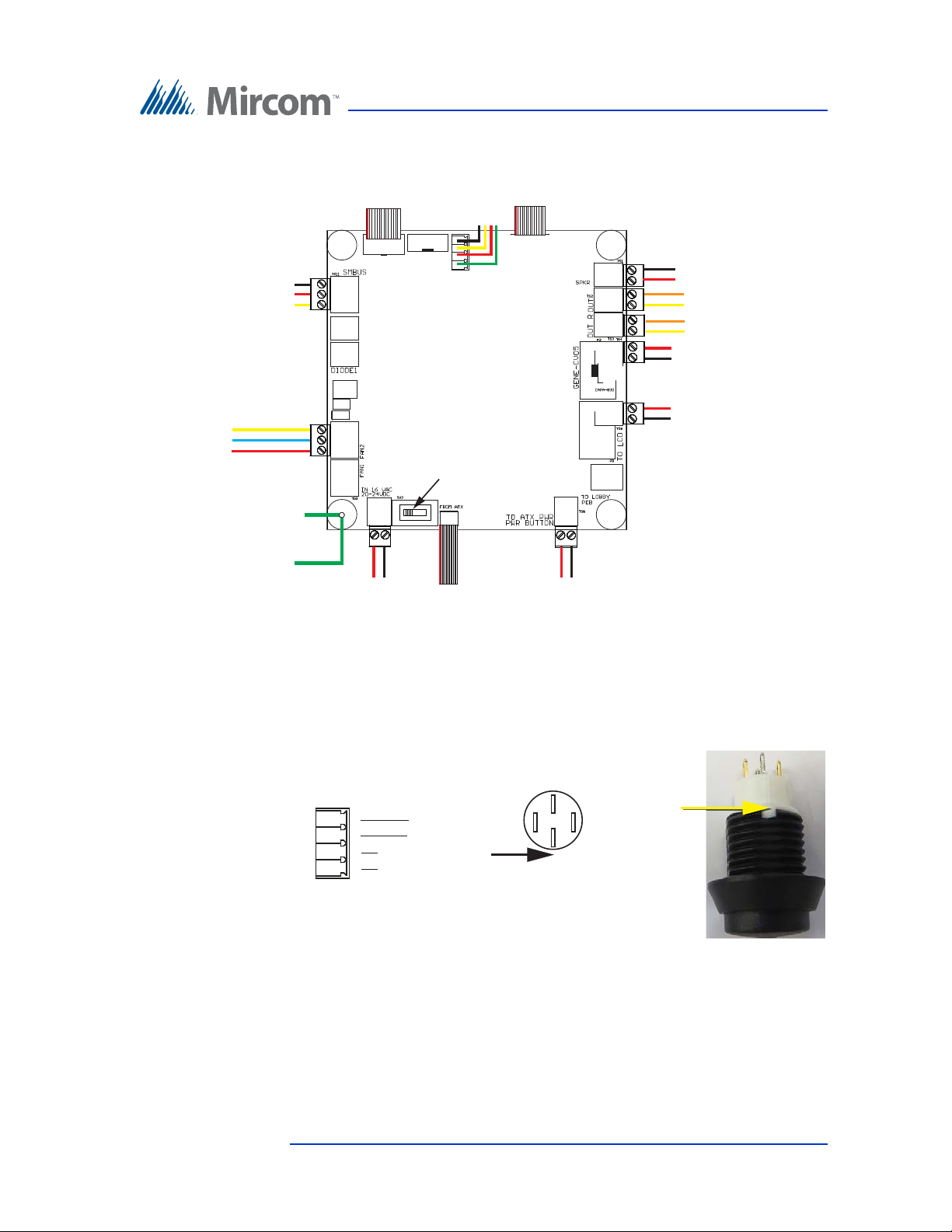
Touch Screen System and Setup
+
-
P5 P1
TS1
TS2
TS3
TS4
TS8
P4
TS5
SW-207: Button
TS6
+
-
TS7
SW3 on the LEFT
SW3
TS11
WX-079: CN31 on PC board
WX-081: CN1 on PC board
WX-520: CN4
on PC board
only if fan is
present
Black (ground)
White (data)
Red (clock)
WR-21160 and
WR-21162: Power
terminals
+
-
WX-070:
Ground wire to
chassis ground
WX-070: Ground
wire to telephone
access controller
WX-080: CN2
on PC board
WX-109: TS2 on telephone
access controller
+
-
MD-1117: Power on
22 inch display
WR-21160 and WR-21162:
Power (CN6)
on PC board
WR-12223 and WR-12224:
Left Speaker
WR-12223 and WR-12224:
Right Speaker
-
+
-
+
+
-
WX-110: TS4 (bottom)
on telephone access
controller
Fan (if present)
YY
B
R
green
1
black
white
red
TS7 on
MD-1105
2
3
4
Button (bottom view)
Notch
Notch
Button (side view)
green
white
red
black
3.13.2 Factory Wiring for TX3-TOUCH-S22 and TX3-TOUCH-F22 with MD-1105
Figure 94. Factory connections on the power supply and audio
mixer board for TX3-TOUCH-S22 and TX3-TOUCH-F22
Version 4.2 TX3 Touch Screen Installation Manual 99 (126)
LT-996 Copyright 2017
Figure 95. Wiring the button
Page 100
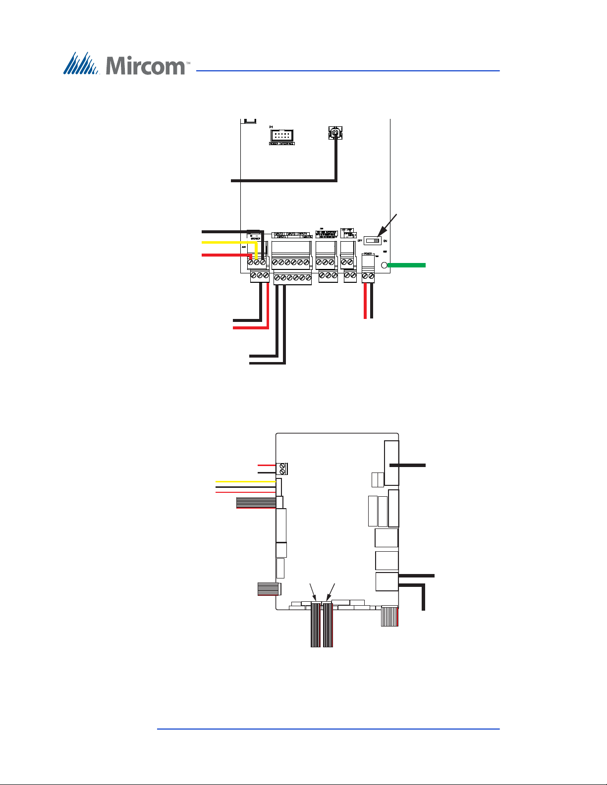
Touch Screen System and Setup
TS4
JP1
Postal lock switch
(optional)
TS5
TS2
Power switch ON
WX-053: USB on
PC board
WX-110: TS1 on
MD-1105
+
WX-109: TS8 on
MD-1105
+
-
WX-070:
Ground wire
to MD-1236
WX-077:
Microphone
B
W
R
+
-
CN6
CN2
CN1
CN31
CN15
CN32
Camera
USB
CN14
CN4
WR-21160 and
WR-21162: TS4 on
MD-1105
WX-520: TS11 on
MD-1105 only if
fan is present
NOTE: Use only
the top 3 pins
Black (ground)
White (data)
Red (clock)
WX-080: P4 on
MD-1105
WX-081: P5 on
MD-1105
WX-082:
USB to display
WX-089:
USB extension
WX-079: P1 on
MD-1105
WX-053: JP1 on
telephone access
controller
Touch Screen VGA
cable
100 (126) TX3 Touch Screen Installation Manual Version 4.2
LT-996 Copyright 2017
Figure 96. Factory connections on the telephone access controller
board for TX3-TOUCH-S22 and TX3-TOUCH-F22 for
MD-1105
Figure 97. Factory connections on the PC sub compact board for
TX3-TOUCH-S22 and TX3-TOUCH-F22 for MD-1105
 Loading...