

Page 1
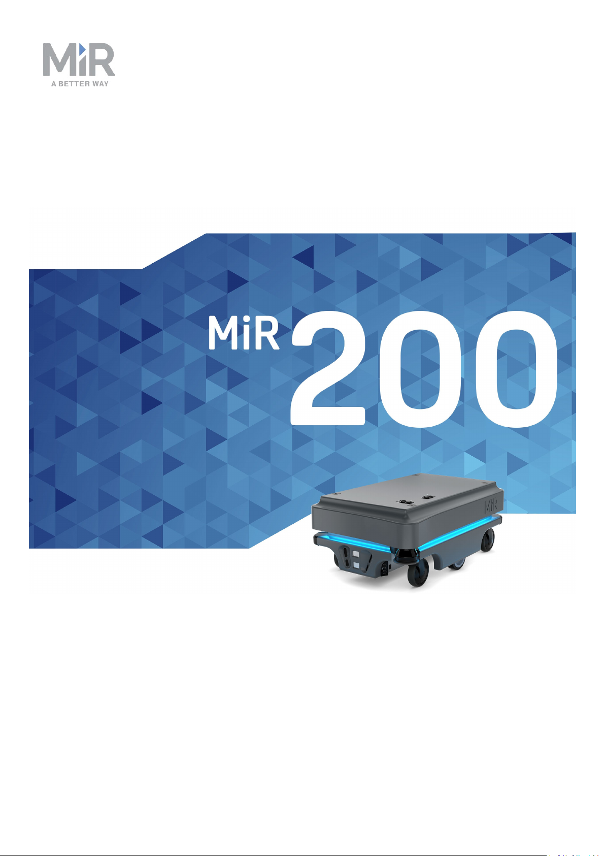
User guide (en)
Date: 09/2019
Revision: v.1.4
Page 2

Copyright and disclaimer
All rights reserved. No parts of this manual may be reproduced in any form without the
express written permission of Mobile Industrial Robots A/S (MiR). MiR makes no warranties,
express or implied, in respect of this document or its contents. In addition, the contents of
the document are subject to change without prior notice. Every precaution has been taken in
the preparation of this manual. Nevertheless, MiR assumes no responsibility for errors or
omissions or any damages resulting from the use of the information contained.
Copyright © 20162017-2019 by Mobile Industrial Robots A/S.
Contact the manufacturer:
Mobile Industrial Robots A/S
Emil Neckelmanns Vej 15F
DK-5220 Odense SØ
www.mir-robots.com
Phone: +45 20 377 577
Email: [email protected]
CVR: 35251235
MiR200 User guide (en) 09/2019 - v.1.4 ©Co pyright 2019: Mobile Industrial Robo ts A/S. 2
Page 3
Table of contents
1. About this document 5
1.1. Where to find more information 5
1.2. Document history 6
2. Safety 7
2.1. Safety message types 7
2.2. General safety precautions 8
2.3. Intended use 10
2.4. Foreseeable misuse 10
2.5. Risk assessment 11
2.6. Residual risks 12
2.7. Safety-related functions and interfaces 12
2.8. Limiting safety-related functions 12
2.9. Lithium battery 14
3. Getting started 15
3.1. In the box 15
3.2. Unpacking MiR200 16
4. Commissioning 18
4.1. Powering up 18
4.2. Connecting to the robot interface 23
4.3. Driving the robot in manual mode 24
4.4. Checking the hardware status 26
4.5. Charging the robot 26
4.6. Shutting down the robot 29
5. Product presentation 30
5.1. Main features of MiR200 30
5.2. Identification label 32
5.3. MiR200 external parts 32
5.4. MiR200 internal parts 34
Page 4
5.5. Sensor system 35
5.6. Light indicators 42
6. Maintenance 43
6.1. Regular weekly checks and maintenance tasks 43
6.2. Regular checks and replacements 44
6.3. Packing for transportation 47
7. Applications 49
7.1. Mounting a top module 49
8. Payload specifications 51
9. Interface specifications 58
9.1. Application interface 58
9.2. Emergency stop 58
10. Updating MiR200 software 60
Page 5
1. About this document
1. About this document
This document contains the following information:
• How to start up and operate MiR200.
• Product presentation.
• Typical applications.
• Guidelines for proper maintenance of the robot.
1.1. Where to find more information
At www.mir-robots.com, several additional resources are available. To access more
information, sign in to the Distributor site with your distributor account at
http://www.mobile-industrial-robots.com/en/account/. The following relevant resources are
available:
• Distributor site > Manuals
http://www.mobile-industrial-robots.com/en/account/manuals/
This page contains the following resources:
- MiR200 Quick start
The short guide that lets you start operating the robot quickly. This document is in the
box with the robot in the printed format. Available in multiple languages.
- MiRCharge 24V Operating guide
The operating guide that describes how to set up MiRCharge 24V and configure
MiR200 for automatic battery charging at the charging station.
- MiR Robot Reference guide
The reference that describes the elements of the robot interface. Available in multiple
languages.
- MiR200 REST API reference.
The REST API reference for MiR100/MiR200the robot.
• Distributor site > Download
http://www.mobile-industrial-robots.com/en/account/download/
This page contains the following resources:
- CAD drawings.
Select Show CAD-files to see the list of available CAD drawings.
- Certificates.
Select Show Certificates to see the list of certificates for the robot.
MiR200 User guide (en) 09/2019 - v.1.4 ©Co pyright 2019: Mobile Industrial Robo ts A/S. 5
Page 6
1. About this document
• Distributor site > How to
http://www.mobile-industrial-robots.com/en/account/how-to/
This page contains how-to articles that describe how to perform specific tasks with MiR
products.
• Distributor site > Troubleshooting
This page contains troubleshooting guides to solve common issues with MiR products.
• MiR200 product page
http://www.mobile-industrial-robots.com/en/products/mir200/
This page contains specifications, pictures, and brochures for MiR200.
• Universal Robots:
http://www.universal-robots.com/support
1.2. Document history
This table shows latest and previous versions of this document and their interrelations with
product software releases.
Revision
Release
date
1.0 2017-1124
1.1 2018-0817
1.2 2018-1128
1.3 2019-0626
1.4 2019-0820
Description SW HW
First edition. 2.0 1.0
Updated for hardware release 1.2
2.2.0 and
1.2
higher
Updates and improvements throughout
manual
Updated for hardware release 2.0
2.3.0 and
2.0
higher
Updates and improvements throughout
manual
Updated for hardware release 3.0
2.6.0 and
3.0
higher
Updates and improvements throughout
the manual
Updated for hardware release 5.0
2.7.6 and
5.0
higher
Updates and improvements throughout
the manual
MiR200 User guide (en) 09/2019 - v.1.4 ©Co pyright 2019: Mobile Industrial Robo ts A/S. 6
Page 7
2. Safety
Read the information in this section before powering up and operating MiR200.
Pay particular attention to the safety instructions and warnings.
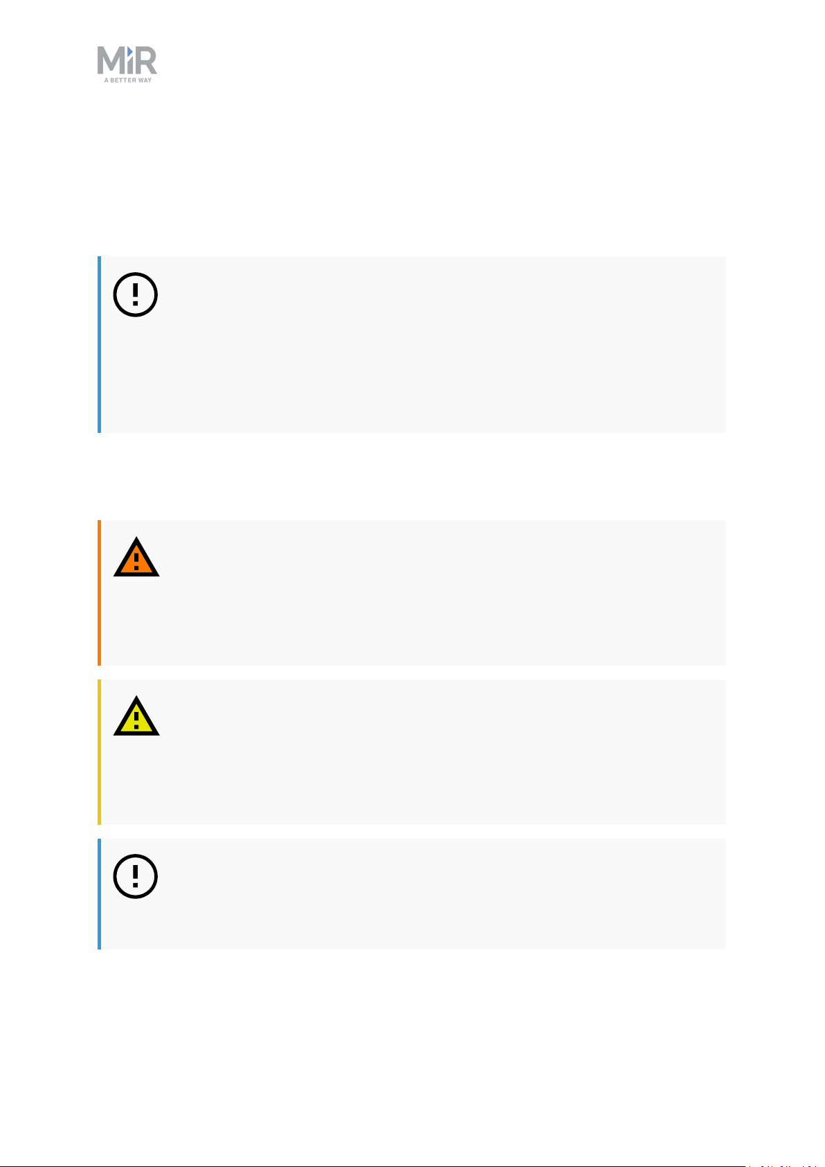
NOTICE
Mobile Industrial Robots disclaims any and all liability if MiR200 or its
accessories are damaged, changed or modified in any way. Mobile Industrial
Robots cannot be held responsible for any damages caused to MiR200,
accessories or any other equipment due to programming errors or
malfunctioning of MiR200.
2.1. Safety message types
2. Safety
This document uses the following safety message types.
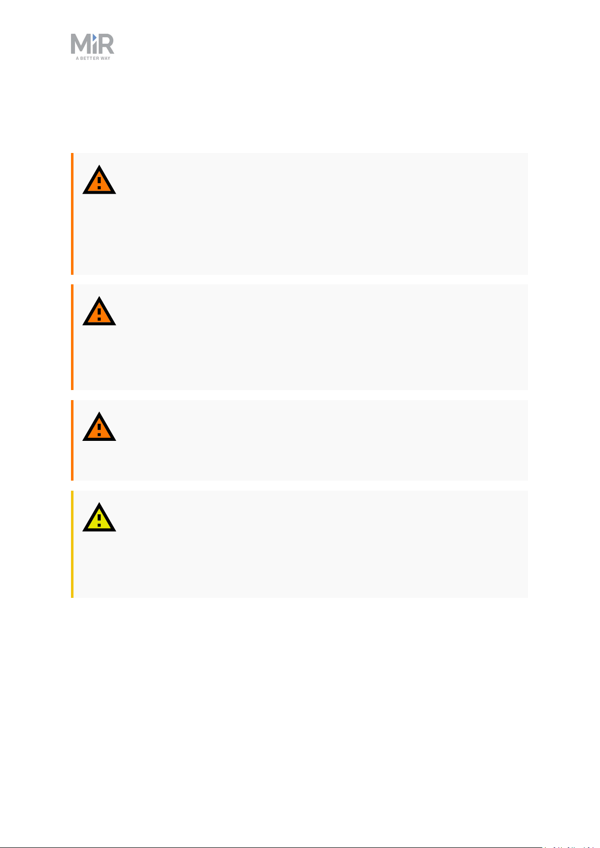
WARNING
Indicates a potentially hazardous situation that could result in death or serious
injury.
• Take proper precautions to avoid damage or injury.
CAUTION
Indicates a potentially hazardous situation that could result in minor or moderate injury. Alerts against unsafe practices.
• Take proper precautions to avoid damage or injury.
NOTICE
Indicates important information, including situations that can result in damage
to equipment or property.
MiR200 User guide (en) 09/2019 - v.1.4 ©Co pyright 2019: Mobile Industrial Robo ts A/S. 7
Page 8
2.2. General safety precautions
This section contains general safety precautions.
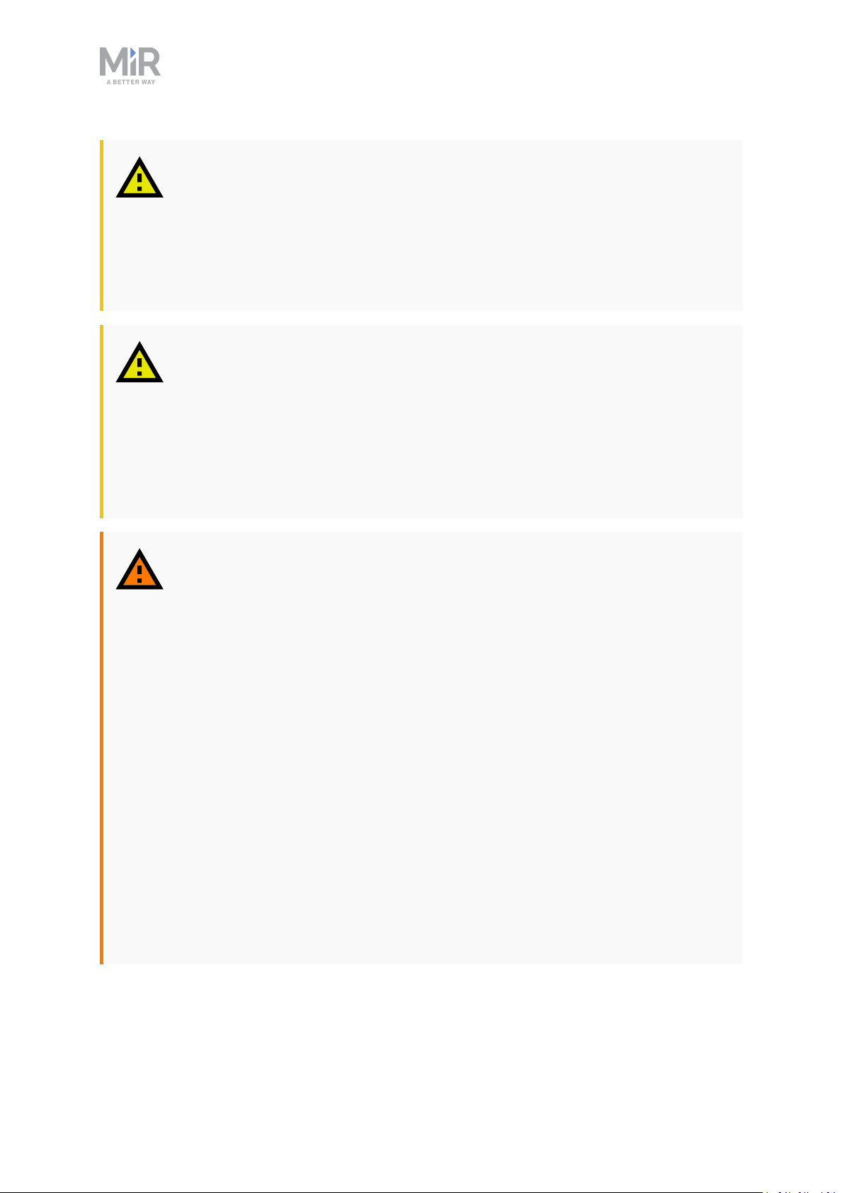
WARNING
If the load on the robot is not positioned or fastened correctly, the load may
fall or the robot may overturn.
• Ensure that the load is positioned according to the specifications and
fastened correctly. Refer to Payload specifications on page51
WARNING
Using a charger different from the one supplied by the manufacturer can
cause a fire.
2. Safety
• Use only the original charger.
WARNING
Make sure the UR Robot Arm is properly and securely bolted in place.
Unstable mounting can lead to accidents.
CAUTION
The robot can not see staircases going downwards and holes in the floor.
• Mark staircases or holes on maps with Forbidden zones.
• Keep the maps up to date.
MiR200 User guide (en) 09/2019 - v.1.4 ©Co pyright 2019: Mobile Industrial Robo ts A/S. 8
Page 9
2. Safety
CAUTION
Removing the top cover from the robot exposes parts connected to the power
supply.
• Turn off the main power relay to avoid a short circuit. To see the location of
the power relay, refer to Product presentation on page30
CAUTION
Use Flight Mode with smartphone control of the robot. Risk of personal injury
and/or damage to the robot.
• If you use Manual control with a smartphone to drive the robot, make sure
that the phone is set to Flight Mode. An incoming call on the smartphone
will interrupt control of the robot.
WARNING
Lithium battery packs may get hot, explode or ignite and cause serious injury if
they are abused electrically or mechanically.
Observe the following precautions when handling and using lithium batteries:
• Do not short-circuit, recharge or connect with false polarity.
• Do not expose to temperature beyond the specified temperature range or
incinerate the battery.
• Do not crush, puncture or disassemble the battery. The battery contains
safety and protection devices, which, if damaged, may cause the battery to
generate heat, explode or ignite.
• Do not allow the battery to get wet.
• In the event the battery leaks and the fluid gets into one’s eye, do not rub
the eye. Rinse well with water and immediately seek medical care. If left
untreated, the battery fluid could cause damage to the eye.
• Use only the original charger (cable charger or charging station) and
always follow the instructions from the battery manufacturer.
MiR200 User guide (en) 09/2019 - v.1.4 ©Co pyright 2019: Mobile Industrial Robo ts A/S. 9
Page 10

2. Safety
2.3. Intended use
MiR200 is intended to be commissioned and used in indoor industrial environments where
access for the public is restricted. For details about the environmental conditions in which
the robot should operate, see Technical specifications on our website.
MiR200 is intended to be commissioned according to Commissioning on page18 and
prepared to the environment according to the guidelines. This is a prerequisite for safe
usage of MiR200.
MiR200 is designed and all risks are considered when used with one of the following types of
top applications:
• MiRHook 200 to tow trailers.
• A custom designed top application (including payload) designed to fulfill the following
requirements:
- Must not increase the footprint of MiR200 and be within the requirements in Payload
specifications
- Must not have any moving parts
MiR200 can be used as a partly complete machine as defined in the EU machinery directive,
with top applications that do not meet above limitations. Those who design, manufacture or
commission a system that does not meet the limitations of use of MiR200, carry the
obligations of a manufacturer and shall ensure a safe design according to EN ISO 12100.
Guidelines outlined in this manual are not sufficient. Examples of top applications, which are
not intended use of MiR200, but not limited to, are:
• Shelf on supporting legs (with or without wheels)
• Top applications (including payload) which increase the footprint of MiR200
• Conveyers (power and non-powered)
• Industrial robot arm
• Customized load transfer station
2.4. Foreseeable misuse
Any use or application deviating from the intended use is deemed to be misuse. This
includes, but is not limited to:
• Use of the robot to transport people.
Risk of injury.
MiR200 User guide (en) 09/2019 - v.1.4 ©Co pyright 2019: Mobile Industrial Robo ts A/S. 10
Page 11

2. Safety
• Steep ramps on the route.
Risk of injury. Steep surface grades (ramps etc.) may cause the robot to skid. See Technical specifications on the website.
• Use outdoor.
Risk of injury. MiR200 is designed and intended for indoor use only.
• Overloading of the robot.
Risk of injury. If the maximum payload on top of the robot is exceeded, it may cause overturning, falling load. See Technical specifications on the website.
• Failure to follow the guidelines for commissioning
See Commissioning on page18.
• Failure to make a risk assessment of the full installation
See Risk assessment below. This applies to the robot with any extra modules installed.
• Operation outside the permissible operating rating parameters and environmental
specifications
Risk of instability, impact or tipping over.
• Transportation of liquids or food
Risk of instability.
• Use in potentially explosive environments
• Use in medical and life critical applications
2.5. Risk assessment
One of the most important steps in achieving a safe installation is to make a risk assessment.
The risk assessment is the responsibility of the individuals who are commissioning MiR200 in
the environment it will be used in. Most often it will be an integrator who also designs
and/or builds work cells or other required infrastructure related to MiR200.
The risk assessment must cover not only MiR200 itself, but also take into account potential
potential load transfer stations, work cells and the environment it will be used in. See
MiR100 and MiR200 Risk Analysis on the distributor page.
It is recommended that the integrator uses guidelines in ISO 12100, EN 1525, ANSI B56.5 or
other relevant standards to conduct the risk assessment.
The risk assessment shall at least consider the following scenarios:
• Detailed description of the robot installation.
• Normal operation of the robot installation.
MiR200 User guide (en) 09/2019 - v.1.4 ©Co pyright 2019: Mobile Industrial Robo ts A/S. 11
Page 12
2. Safety
In EN 1525, clause 4 there is a list of significant hazards, hazardous situations and events
which can be used for inspiration.
The risk assessment shall be written and saved as part of the technical file.
2.6. Residual risks
Mobile Industrial Robots has identified the potential significant hazards listed below as
hazards that must be considered by the integrator.
• Being run over, drawing-in, trapping or impact if a person steps into the route or walks
towards MiR200 while driving in reverse. The MiR200 will only drive in reverse when parking or picking up a cart or undocking from a marker such as the MiRCharge 24V.
• Crushing or trapping if user touches MiR200. Please notice the warnings on MiR200.
• Crushing, drawing-in or trapping at load transfer stations, work cells or charging stations.
NOTICE
Other significant hazards will be present in a specific robot installation and
shall be identified during Commissioning.
2.7. Safety-related functions and interfaces
MiR200 is equipped with a range of built-in safety-related functions as well as safety-related
electrical interfaces designed for integration with a top module and/or top manipulator.
Each safety function and interface is designed according to the standard ISO 13849-1.
The safety-related functions and interfaces are selected to support compliance with EN
1525.
2.8. Limiting safety-related functions
MiR200 has several built-in safety-related functions that are used to ensure safe operation in
the environment it is designed to be used in.
Advanced control software ensures that locomotion and the drive pattern are within safety
related limits and thereby avoid triggering a safety function. Violations of limits will hence
only occur in exceptional cases. Nevertheless, if a limit is violated, the safety system issues a
category 0 stop (stopping by “immediate removal of power to the machine actuators
according to IEC 60204-1”) followed by a controlled brake which brings MiR200 to a stop.
See Technical specifications on our website for more details.
MiR200 User guide (en) 09/2019 - v.1.4 ©Co pyright 2019: Mobile Industrial Robo ts A/S. 12
Page 13

2. Safety
Collision avoidance
The collision avoidance safety function ensures that the robot will come to a stop before it
collides with a human or object.
The function measures the speed on the two driving wheels and switches between the
predefined protective fields accordingly. The faster the speed, the larger the protective
fields will be.
This ensures that the robot will be brought to a stop in case a human or object is detected
within the active protective field.
Collision avoidance is automatically deactivated two seconds after the protective field is
free.
Overspeed avoidance
The safety system monitors if the speed of each motor is above limits for maximum rated
speed and hence an indication of speed control is lost for any reason.
The overspeed avoidance safety function must be manually deactivated by activation of the
restart button.
Emergency stop
MiR200 has one emergency stop device.
The emergency stop is only intended to be used in case of an emergency and shall not be
used for operational stop.
Emergency stop must be manually deactivated by activation of the restart button.
MiR200 User guide (en) 09/2019 - v.1.4 ©Co pyright 2019: Mobile Industrial Robo ts A/S. 13
Page 14
2.9. Lithium battery
This section contains safety precautions related to lithium batteries in MiR robots.
WARNING
Lithium battery packs may get hot, explode or ignite and cause serious injury if
they are abused electrically or mechanically.
Observe the following precautions when handling and using lithium batteries:
• Do not short-circuit, recharge or connect with false polarity.
• Do not expose to temperature beyond the specified temperature range or
incinerate the battery.
• Do not crush, puncture or disassemble the battery. The battery contains
safety and protection devices, which, if damaged, may cause the battery to
generate heat, explode or ignite.
2. Safety
• Do not allow the battery to get wet.
• In the event the battery leaks and the fluid gets into one’s eye, do not rub
the eye. Rinse well with water and immediately seek medical care. If left
untreated, the battery fluid could cause damage to the eye.
• Use only the original charger (cable charger or charging station) and
always follow the instructions from the battery manufacturer.
MiR200 User guide (en) 09/2019 - v.1.4 ©Co pyright 2019: Mobile Industrial Robo ts A/S. 14
Page 15
3. Getting started
This section describes how to get started with MiR200.
3.1. In the box
This section describes the content of the MiR200 box.
3. Getting started
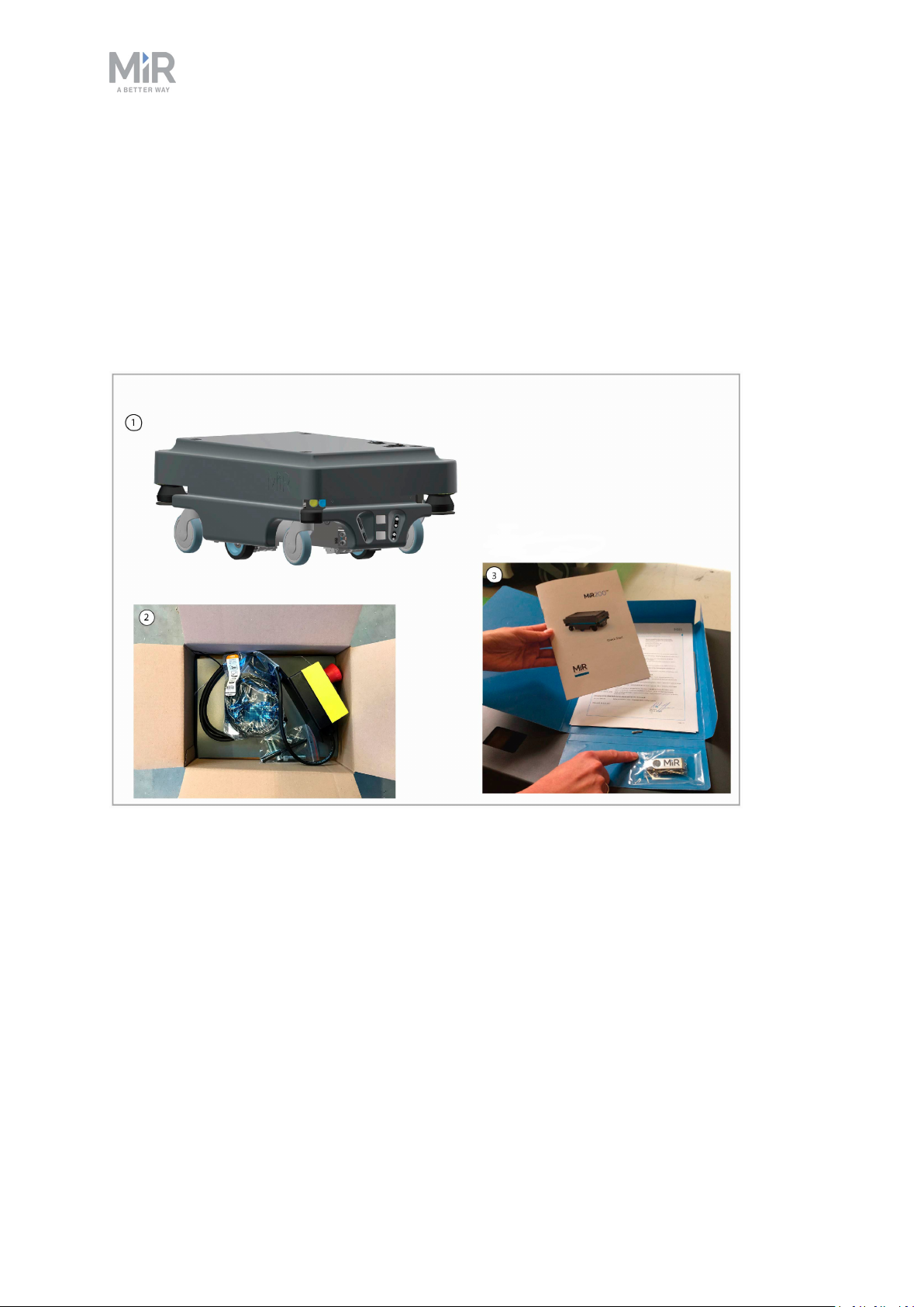
The box contains:
1. The MiR200 robot
2. MiR200 Kit
• Emergency stop box, external antenna and 4 pcs. M10x40 bolts
• One charging cable
• One external charger, 24VDC, 10A
3. MiR200 document folder containing the printed documents and the USB flash drive.
MiR200 User guide (en) 09/2019 - v.1.4 ©Co pyright 2019: Mobile Industrial Robo ts A/S. 15
Page 16
4. Printed documents:
• MiR200 Quick Start
• MiR username and passwords
• CE declaration of conformity
5. USB flash drive with the following content:
• MiR200 User Guide
• MiR Robot Interface 2.0 Reference guide
• MiR robot REST API reference
• MiR username and passwords
• CE declaration of conformity
3.2. Unpacking MiR200
This section describes how to unpack MiR200.
3. Getting started
Keep the original packaging for the future transportation of the robot.
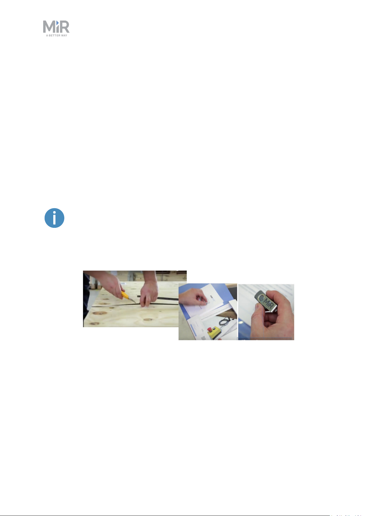
1. Remove pallet lid and take out the box with the MiR200 kit. Keep the original packaging
for future transportation of the robot.
MiR200 User guide (en) 09/2019 - v.1.4 ©Co pyright 2019: Mobile Industrial Robo ts A/S. 16
Page 17
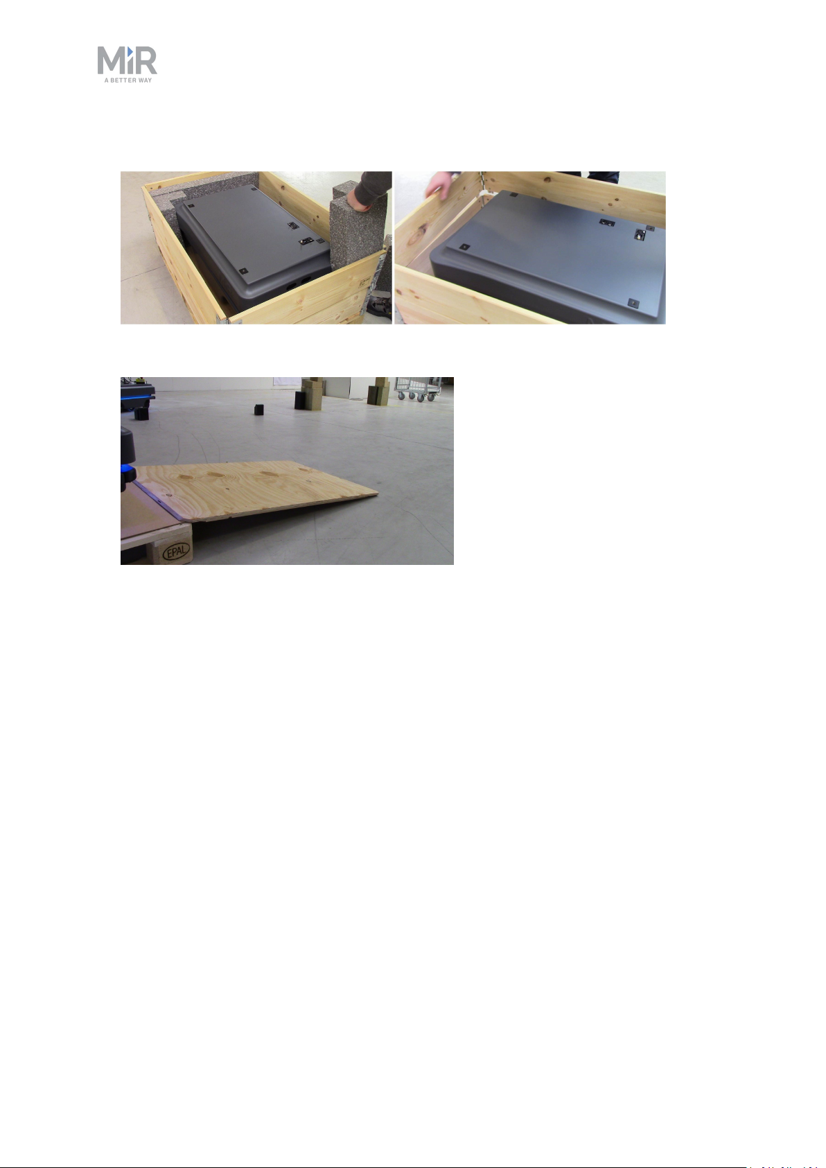
2. Remove the top foam, foam blocks on the sides and the pallet frames.
3. Place the pallet cover as a ramp at the robot's rear end.
3. Getting started
MiR200 User guide (en) 09/2019 - v.1.4 ©Co pyright 2019: Mobile Industrial Robo ts A/S. 17
Page 18
4. Commissioning
This section describes how to get started with MiR200.
NOTICE
Read the Safety chapter before powering up the robot.
4.1. Powering up
Follow these steps to power up MiR200.
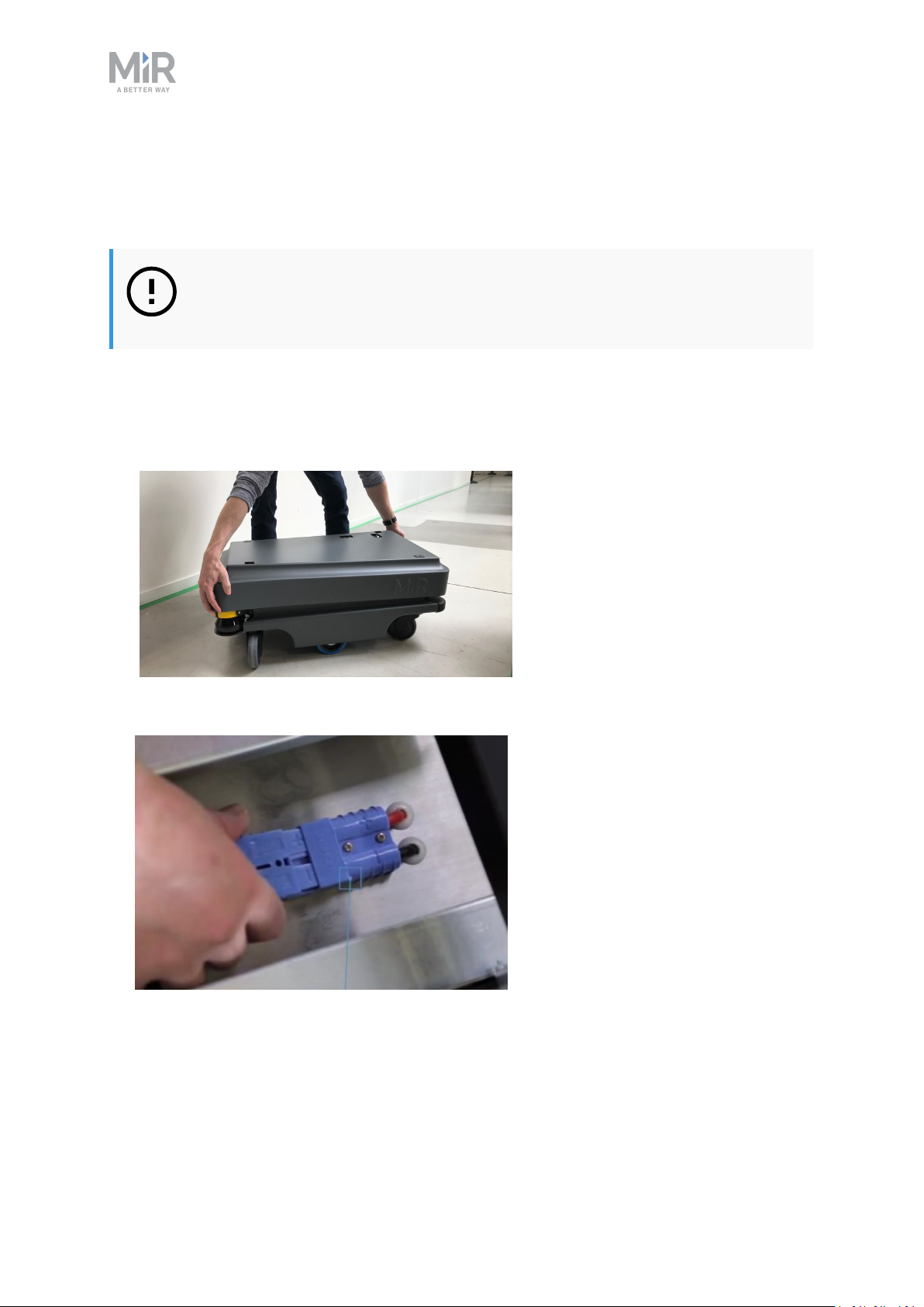
1. Grab the two rounded corners and carefully lift off the cover.
4. Commissioning
2. Connect one of the two battery cables to the plug on top of the battery box. The second
cable is for an extra battery.
MiR200 User guide (en) 09/2019 - v.1.4 ©Co pyright 2019: Mobile Industrial Robo ts A/S. 18
Page 19
4. Commissioning
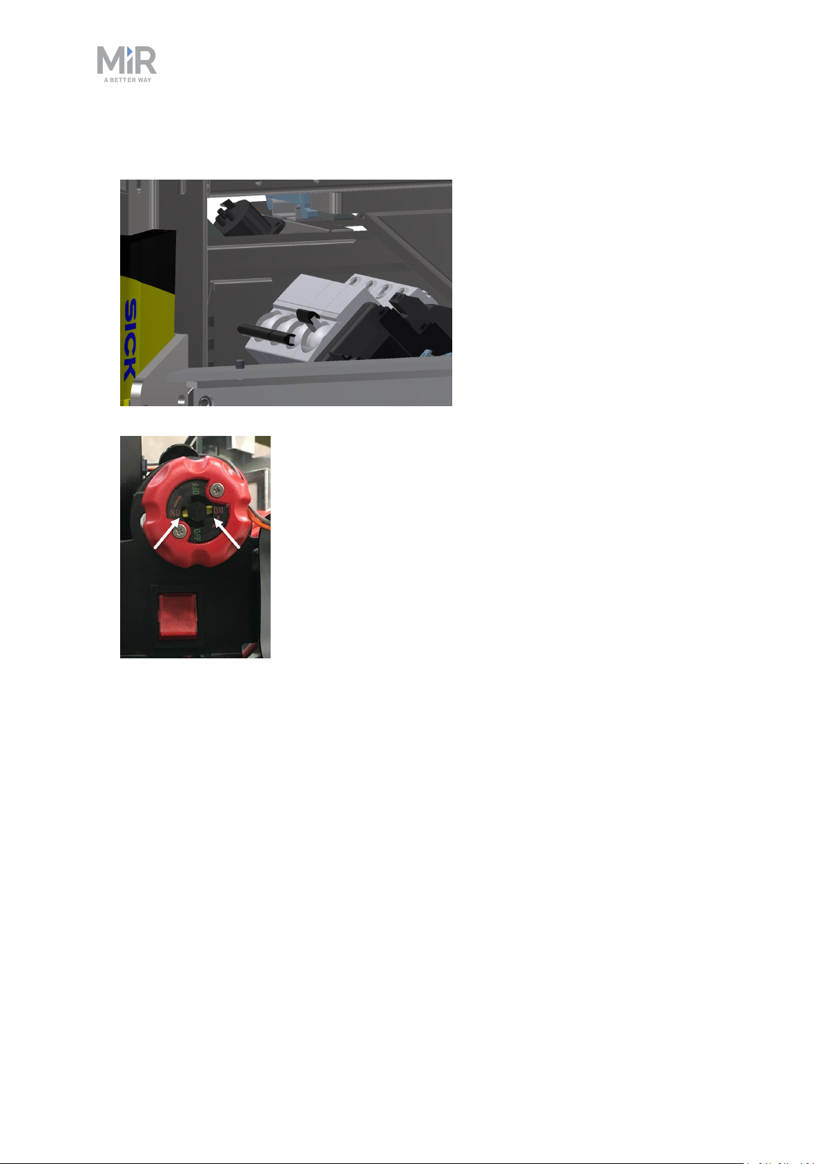
3. Switch on the three relays placed in the corner by the front laser scanner. Start with 32A
main power, i.e. from the outer frame in.
4. Ensure that the battery disconnect switch is on (the two yellow indicators pointing to On).
MiR200 User guide (en) 09/2019 - v.1.4 ©Co pyright 2019: Mobile Industrial Robo ts A/S. 19
Page 20
4. Commissioning
5. Connect the two ESD cables attached to the robot frame, next to the loudspeaker, and
inside the cover.
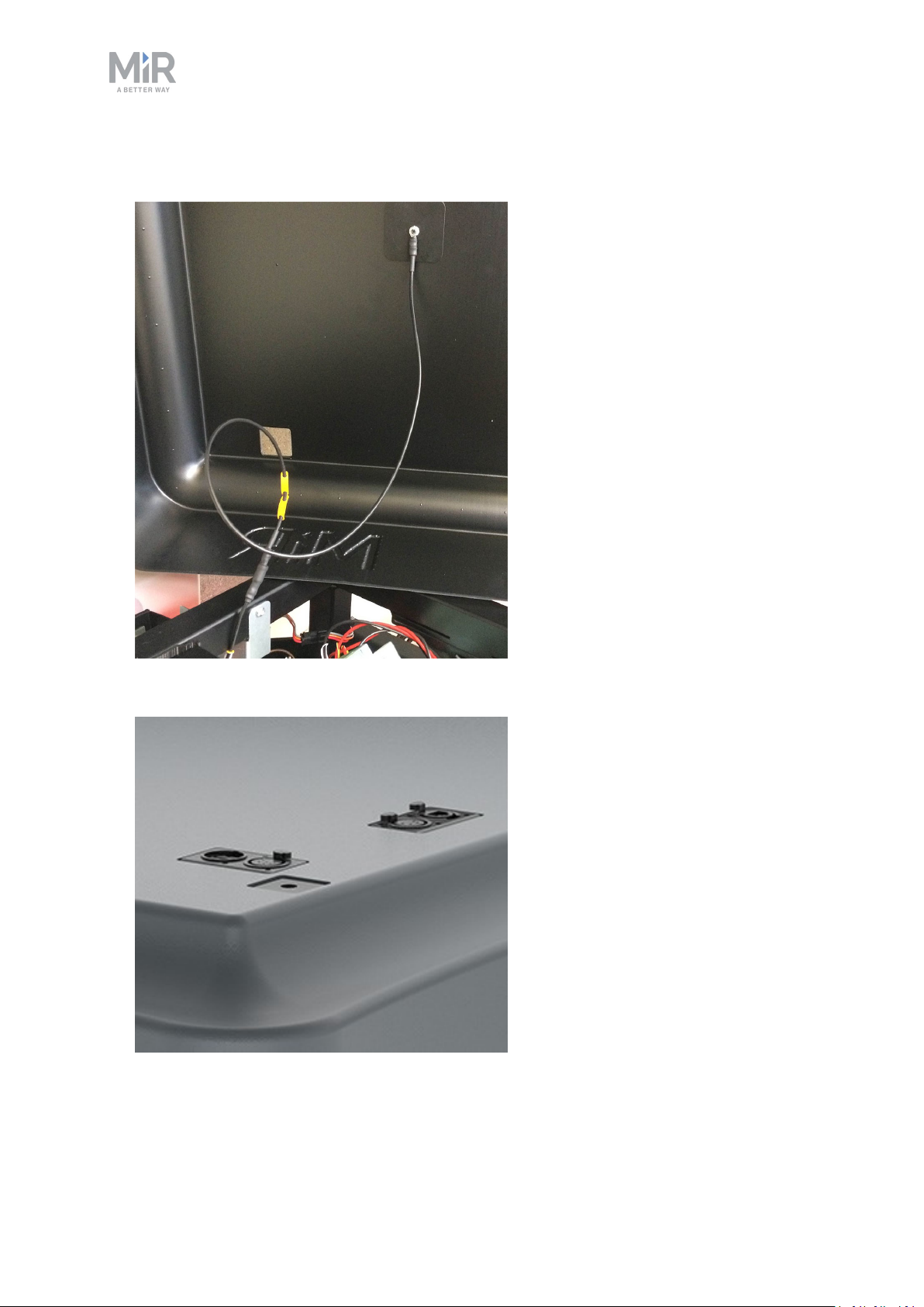
6. Put the cover back on making sure to fit it correctly over the connector openings.
MiR200 User guide (en) 09/2019 - v.1.4 ©Co pyright 2019: Mobile Industrial Robo ts A/S. 20
Page 21
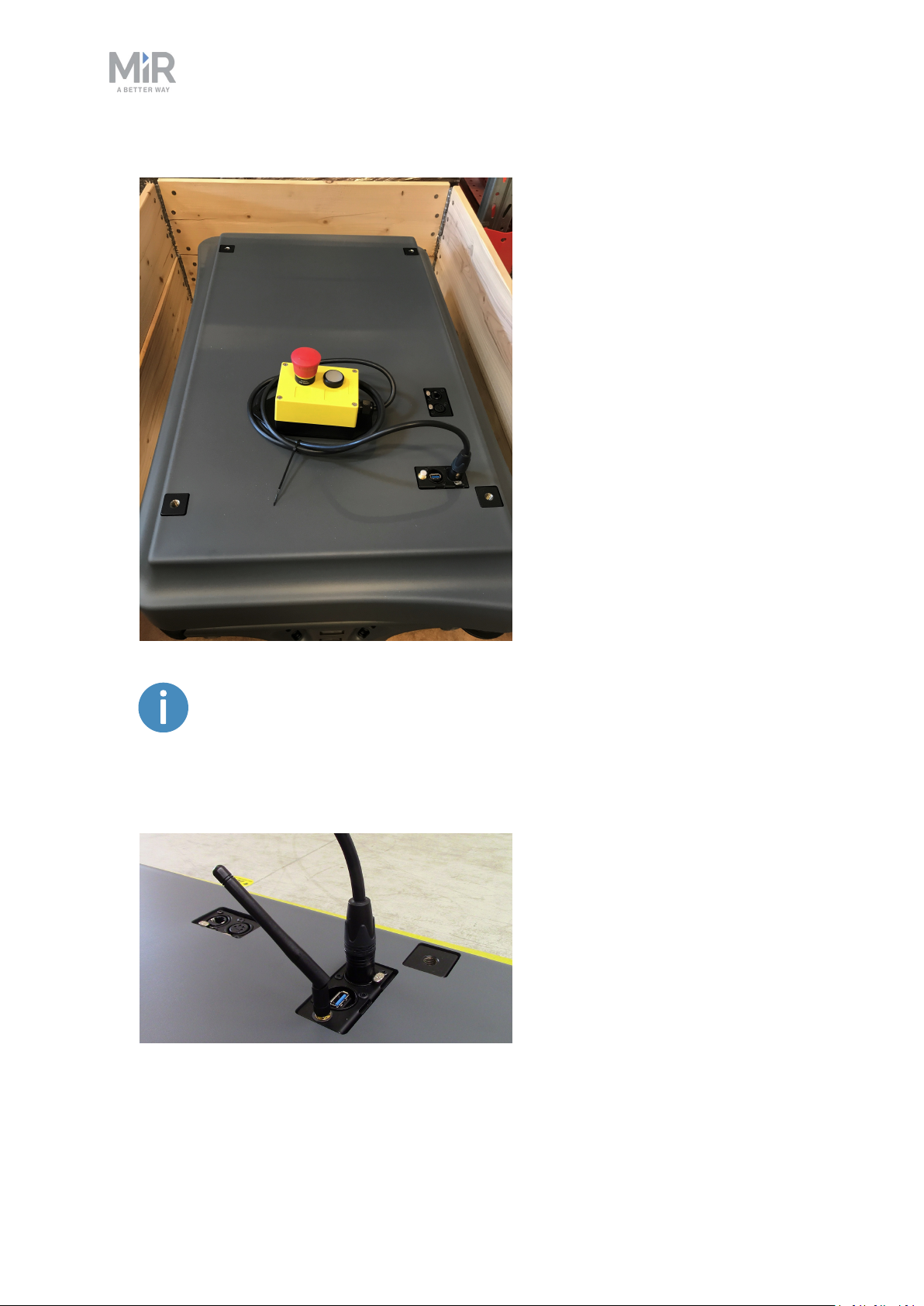
7. Mount and connect the emergency stop box on top of the robot cover.
4. Commissioning
If a top module is going to be mounted on top of the robot, the emergency
stop must be placed in a position where it is easy to reach. See Mounting a
top module on page49.
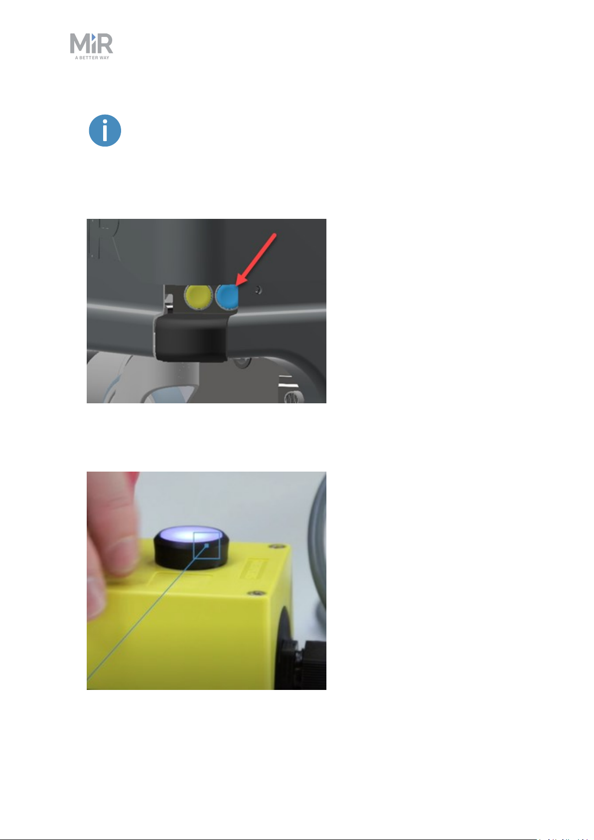
8. Connect the antenna to the connector on top of the robot cover. Remove the plastic cap
from the connector before fixing the antenna.
MiR200 User guide (en) 09/2019 - v.1.4 ©Co pyright 2019: Mobile Industrial Robo ts A/S. 21
Page 22
4. Commissioning
The antenna can be lowered and rotated in all directions to fit under a top
module.
9. Push the blue power button in the corner to turn on the robot. The robot lights up with a
yellow running light for a short moment, then enters emergency stop mode indicated by
a constant red light.
10. Press the reset button on the emergency stop when it has lit up. The robot light now
switches to yellow constant light, indicating that the robot is paused and ready to operate.
MiR200 User guide (en) 09/2019 - v.1.4 ©Co pyright 2019: Mobile Industrial Robo ts A/S. 22
Page 23
4. Commissioning
4.2. Connecting to the robot interface
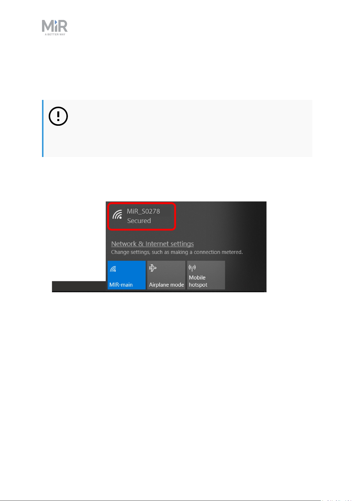
When the robot is on, it enables the connection to its WiFi access point. The name of the
access point appears in the list of available connections on your pc, tablet or phone.
NOTICE
The username and password for the robot’s WiFi access point and for accessing the web interface are in the MiR username and passwords document. The
document is in the box with the robot.
Follow these steps to connect to the robot interface:
1. Using your pc, tablet or phone, connect the WiFi access point of the robot. The access
point name has the following format: MiR_SXXXX.
MiR200 User guide (en) 09/2019 - v.1.4 ©Co pyright 2019: Mobile Industrial Robo ts A/S. 23
Page 24
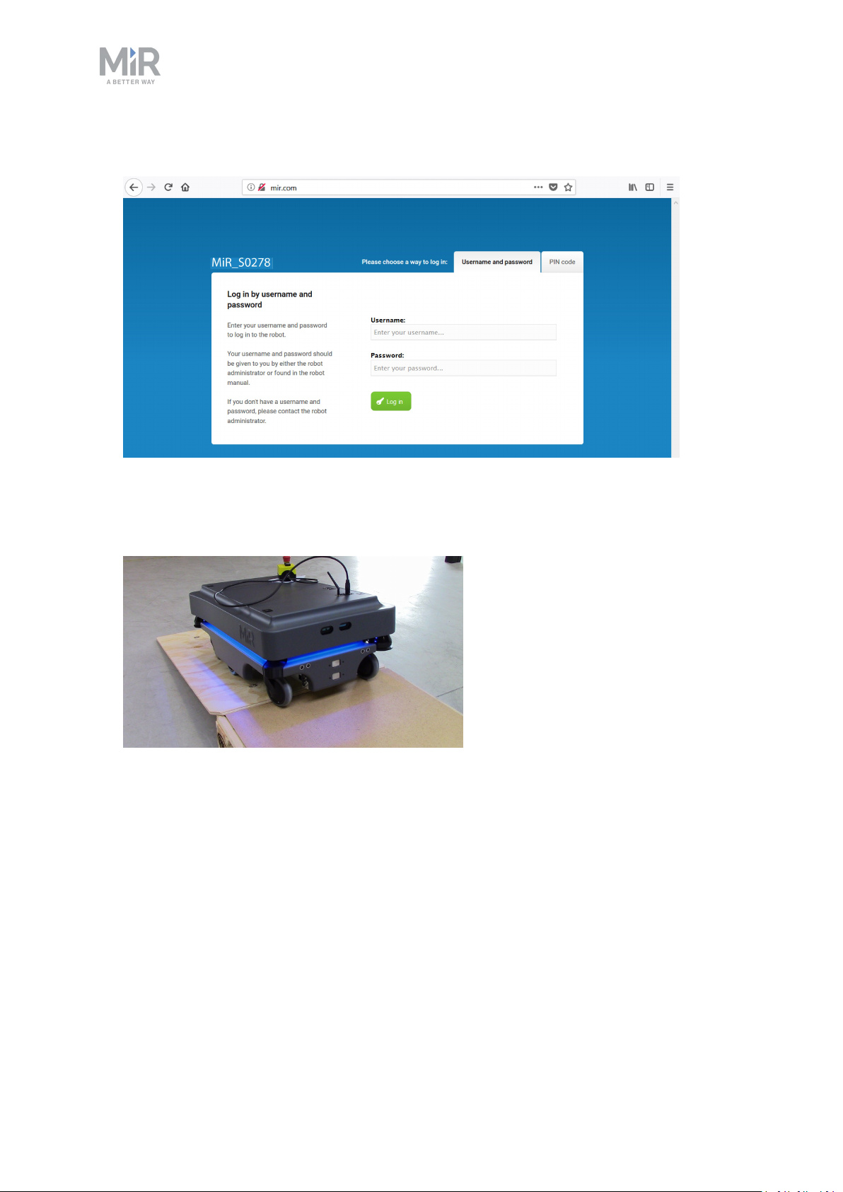
2. In a browser, go to the address mir.com and sign in.
4. Commissioning
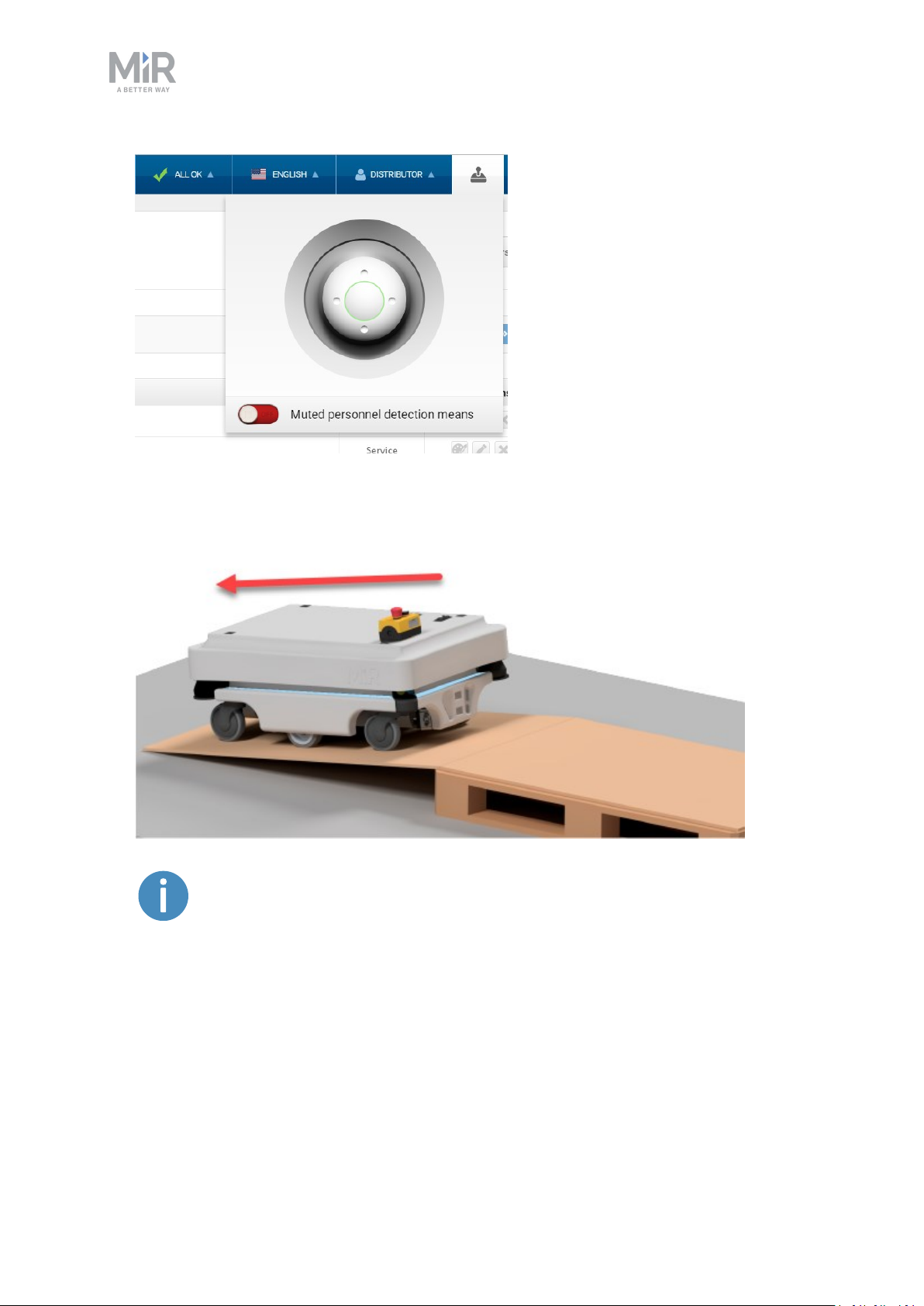
The robot is now ready to move down the ramp. To do this switch to manual mode and
use the electronic joystick in the robot interface. See next section Driving the robot in
manual mode below.
4.3. Driving the robot in manual mode
To drive the robot in Manual mode:
1. In the robot interface, select the joystick icon. Then press Manual control and the joy-
stick control opens.
MiR200 User guide (en) 09/2019 - v.1.4 ©Co pyright 2019: Mobile Industrial Robo ts A/S. 24
Page 25
4. Commissioning
2. The status light on the robot turns blue indicating that the robot is in Manual mode.
3. Drive the robot using the joystick.
We recommend to reverse the robot down the ramp.
MiR200 User guide (en) 09/2019 - v.1.4 ©Co pyright 2019: Mobile Industrial Robo ts A/S. 25
Page 26
4. Commissioning
4.4. Checking the hardware status
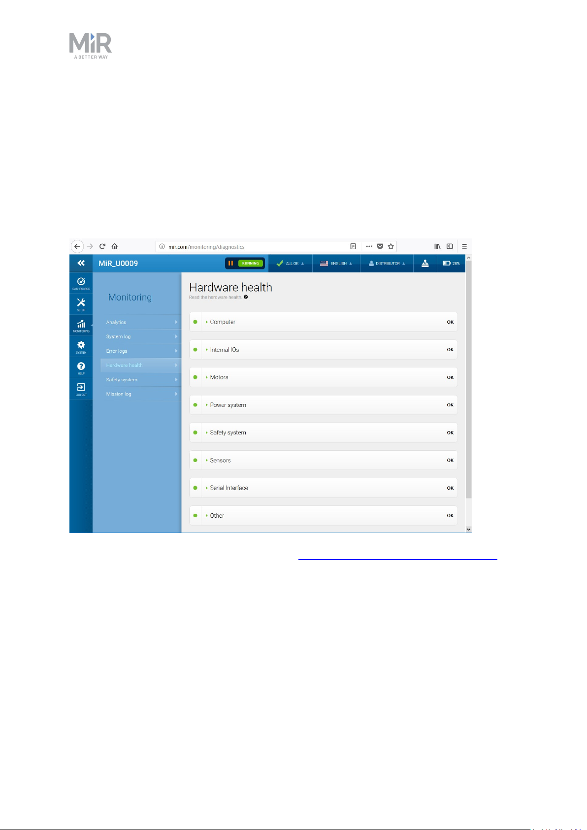
To check that all hardware components work as intended:
Sign in to the robot interface. See the section Connecting to the robot interface on page23.
Go to Monitoring > Hardware health.
Check that all elements on the page have the OK status and that they have green dots on the
left.
For more information, see Hardware health in MiR Robot Interface 2.0 Reference Guide.
4.5. Charging the robot
The robot arrives with a charged battery and can drive for up to three hours before
recharging is required. Follow these steps to charge the robot using the enclosed charging
cable:
MiR200 User guide (en) 09/2019 - v.1.4 ©Co pyright 2019: Mobile Industrial Robo ts A/S. 26
Page 27
4. Commissioning
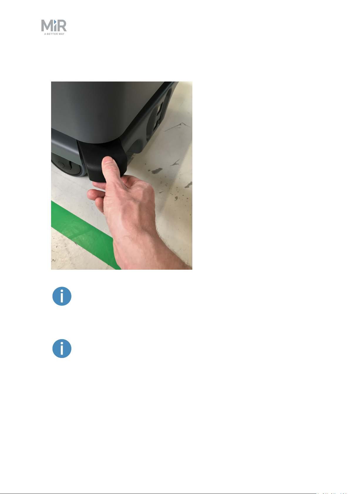
1. Remove the rear corner by pulling it towards you. You may have to apply a bit of force
the first couple of times.
To avoid fast discharging and a depletion of the battery, we recommend
that you turn off the robot while charging with a cable.
If charging two robots right after each other with a cable, wait approximately one minute between unplugging the first robot and plugging in the
second. This will ensure that the charger registers that a new robot is being
charged.
MiR200 User guide (en) 09/2019 - v.1.4 ©Co pyright 2019: Mobile Industrial Robo ts A/S. 27
Page 28
4. Commissioning
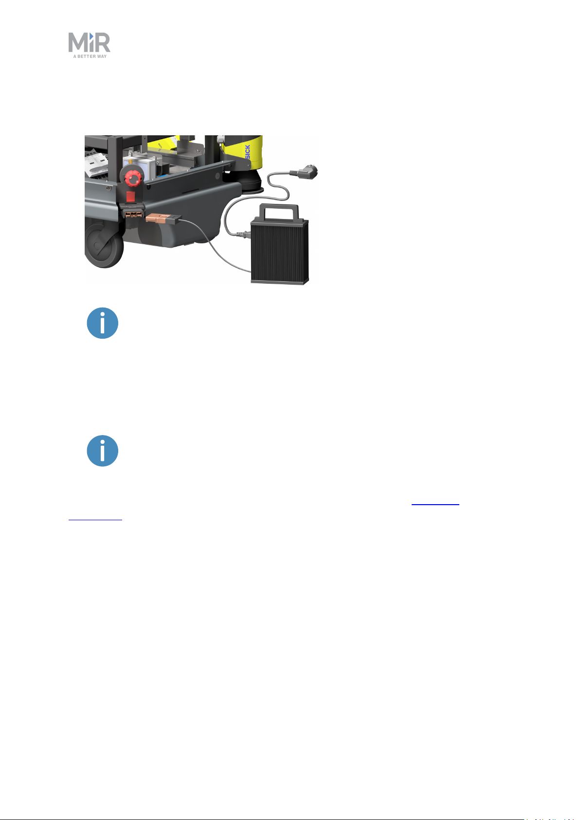
2. Attach the charger to the robot’s charging socket and to a power outlet. Turn on the
rocker switch on the robot to begin charging.
Use only the original charging cable.
3. After a maximum of four and a half hours, the robot is fully charged.
4. Turn off the rocker switch and disconnect the charging cable from the robot. Slide the
corner cover back on.
The robot detects both cable and activated charging-button and will go into
emergency stop in both cases.
For information about the charging time, see the robot specifications at www.mir-
robots.com.
MiR200 User guide (en) 09/2019 - v.1.4 ©Co pyright 2019: Mobile Industrial Robo ts A/S. 28
Page 29
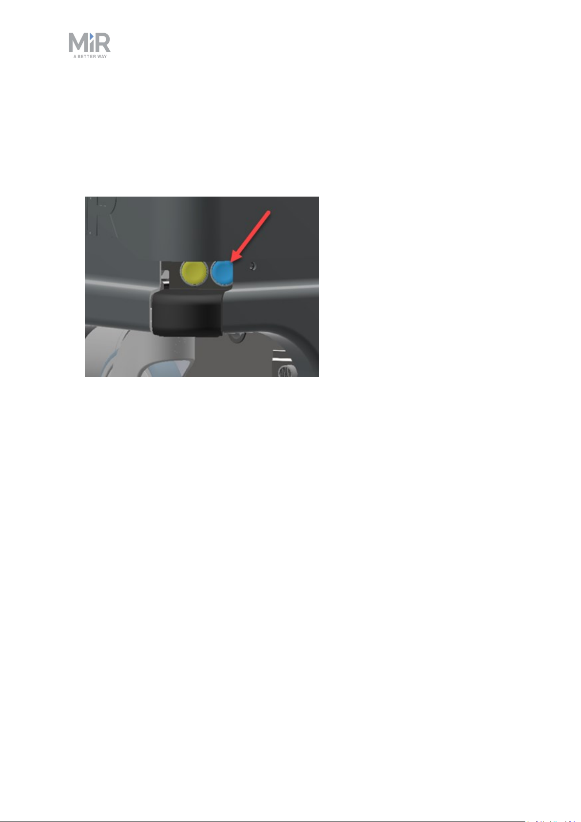
4.6. Shutting down the robot
To shut down MiR200:
1. Ensure that the robot is not moving or executing an action.
2. Press the On/Off button.
4. Commissioning
3. The robot starts the shutdown process. During shutdown, status lights show yellow fading
light.
4. You'll know that the shutdown process is finished when the status lights are off.
If you're shutting the robot down for transportation or service/repair, the battery disconnect
switch must be turned off as well and the battery cable disconnected.
MiR200 User guide (en) 09/2019 - v.1.4 ©Co pyright 2019: Mobile Industrial Robo ts A/S. 29
Page 30

5. Product presentation
5. Product presentation
MiR200 is an autonomous mobile robot that can transport loads up to 200 kg and pallets
indoors within production facilities, warehouses, and other industrial locations.
Users operate MiR200 via a web-based user interface, which is accessed via a browser on a
PC, smartphone or tablet. Each robot has its own network. See Connecting to the robot
interface on page23. The robot can be set up to run a fixed route, be called on demand or
perform more complex operations (missions).
The robot performs localization and navigation via a map which can be created or imported
the first time the robot is used. The internal map contains defined locations (office, product
delivery, production hall etc.) that are used for logistical planning. While operating, the
safety laser scanners ensure that the robot avoids dynamic obstacles (people, furniture) that
are not mapped.
With a MiRCharge 24V, the robot handles moving to a charging station automatically. All it
takes is the definition of a charging mission and a charging position on the map.
5.1. Main features of MiR200
The main features of the MiR200 are:
• Driving in a populated workspace
The robot is designed to operate among people and maneuvers safely and efficiently in
even highly dynamic environments.
• Overall route planning and local adjustments
The robot autonomously navigates to find the most efficient path to its destinations. The
robot adjusts the path when it encounters obstacles which are not on the map (like people
and objects).
• Efficient transportation of heavy loads
The robot is designed to automate transportation of loads up to 200 kg across industries,
allowing employees to focus on higher value activities.
• Sound and light signals
The robot continuously signals with light and sounds indicating its current mode, for
example waiting for job, driving to destination, destination reached or alert mode.
MiR200 User guide (en) 09/2019 - v.1.4 ©Co pyright 2019: Mobile Industrial Robo ts A/S. 30
Page 31
5. Product presentation
• User friendly and flexible
The web-based user interface, accessed from a PC, tablet or smartphone, gives easy
access to operation and monitoring of the robot and can be programmed without any
prior experience. Different user group levels and tailored dashboards can be set up to suit
the different users.
• Alert for ‘lost’
If the robot enters a situation where it is unable to find a path to its destination, it stops,
turns on the yellow-purple running error light and a customer defined ‘catch’ action may
be used to alert people or take other actions.
• Automatic deceleration for objects
The built-in sensors ensure that the robot is slowed down when obstacles are detected in
front of it.
• Optimal surface operations
The robot is made to run on a level, dry floor and 3D cameras detect and avoid objects.
• Internal map
The robot can either use a floor plan from a CAD system or a map can be created by
manual navigation around the entire site in which the robot is going to operate. When
mapping, the robot’s sensors detect walls, doors, furniture and then creates a map based
on this input. After creation of the map, positions and other features can be added in the
map editor.
Add-ons
The following add-ons are available for the MiR200:
• MiRHook 200
A hook may be mounted on MiR200 enabling it to automate the internal transport of
carts.
To read more about the add-ons, go to www.mir-robots.com.
MiR200 User guide (en) 09/2019 - v.1.4 ©Co pyright 2019: Mobile Industrial Robo ts A/S. 31
Page 32
5. Product presentation
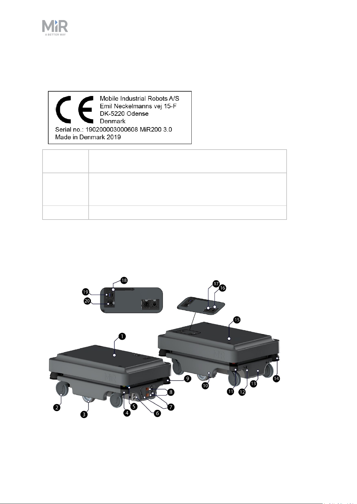
5.2. Identification label
The identification label of MiR200 is placed on the back of the battery box.
CE Mobile Industrial Robots A/S declares that MiR200 meets the
requirements of the applicable EC directives.
Serial
number
MiR200 3.0 Product name and hardware version.
Example of MiR200 CE marking and identification label.
The 15-digit serial number is a unique identifier of the robot. The
last four digits form part of the original name of the robot, e.g.
MiR R635.
5.3. MiR200 external parts
This section presents the parts of MiR200 that are visible on the outside.
MiR200 User guide (en) 09/2019 - v.1.4 ©Co pyright 2019: Mobile Industrial Robo ts A/S. 32
Page 33

5. Product presentation
1. Top cover 11. Behind removable rear corner
cover: Charging port with switch
2. Caster wheel - all four corner
wheels
12. Ultrasound sensors for detection
of transparent objects (rear)
3. Drive wheel - differential control 13. Rear cover
4. Behind removable corner cover:
14. Rear laser scanner
HDMI port and USB “service port”
- connects to the robot’s PC
5. Scanner reset button (yellow) and
on/off button (blue)
6. Ultrasound sensors for detection
15. Mooring hole - one in each corner
for fixation of top modules
16. RJ45 Ethernet connection
of transparent objects (side)
7. 3D depth cameras 17. Application interface - for
connection to hardware such as
hook - see Interface specifications
on page58
8. Pad connectors - for connection to
18. Antenna socket
charging poles on MiRCharge 24V
charging station
9. Front laser scanner 19. USB port “service port” - connects
to the robot's PC
10. Side cover 20. Emergency stop interface with
added options for connection to
small units and I5 input on SICK
scanners - see Interface
specifications on page58
MiR200 external parts
MiR200 User guide (en) 09/2019 - v.1.4 ©Co pyright 2019: Mobile Industrial Robo ts A/S. 33
Page 34
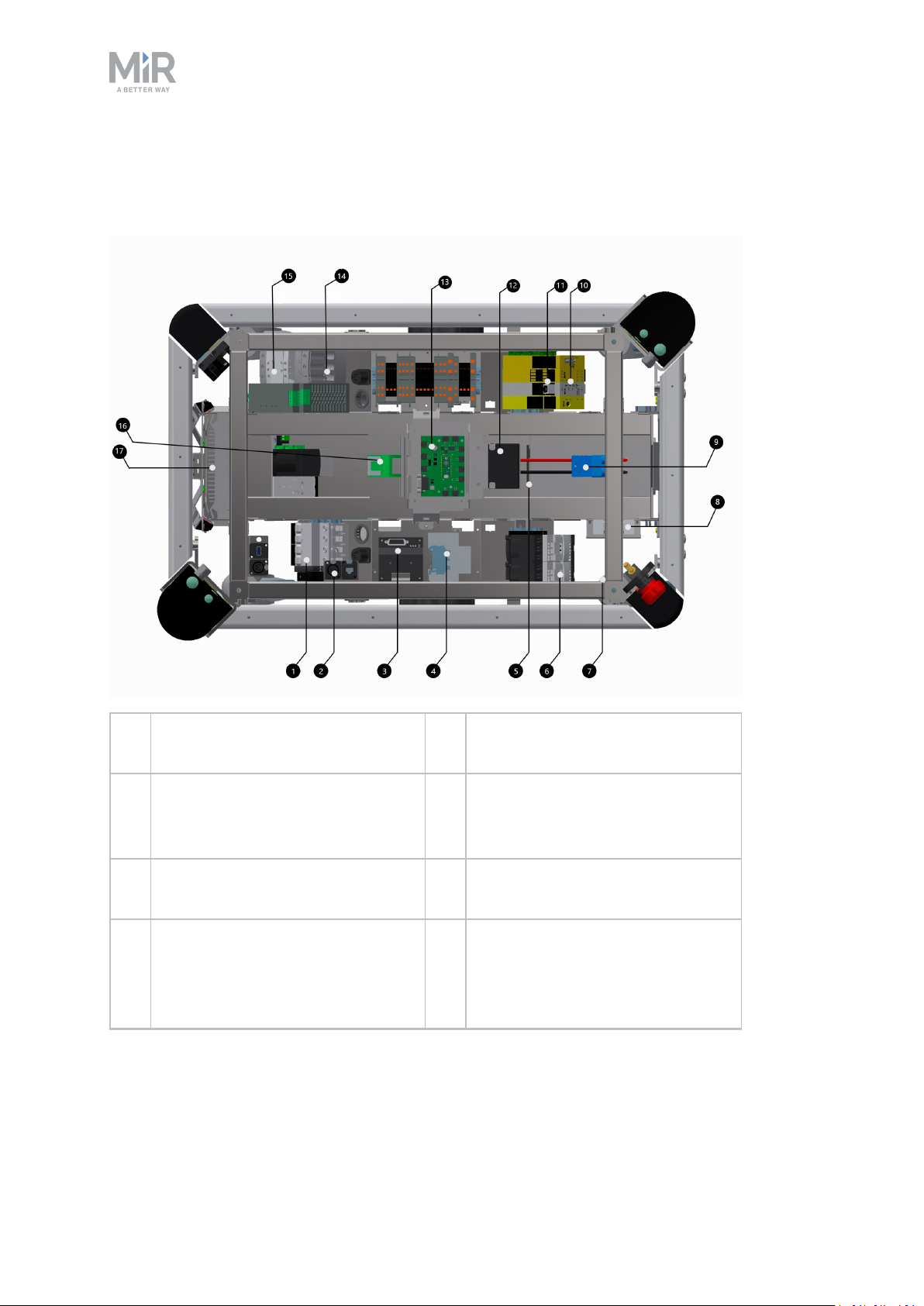
5.4. MiR200 internal parts
This section presents the parts of MiR200 that are visible on the inside.
5. Product presentation
1. Breaker - automatic fuse between
battery and components
2. Robot power off relay - releases
the latching relay (pos. 16) when
the robot is shutting down.
3. Motorcontroller - manages the
two motor drives
4. Brake relay - short circuits motor
windings for faster braking
10. SICK safety PLC
11. Optocoupler - emergency stop
signal to motorcontroller
12. Loudspeaker
13. MiR board - interface board for
gyroscope, accelerometer,
ultrasound, light, on/off circuit
and CAN bus communication
MiR200 User guide (en) 09/2019 - v.1.4 ©Co pyright 2019: Mobile Industrial Robo ts A/S. 34
Page 35
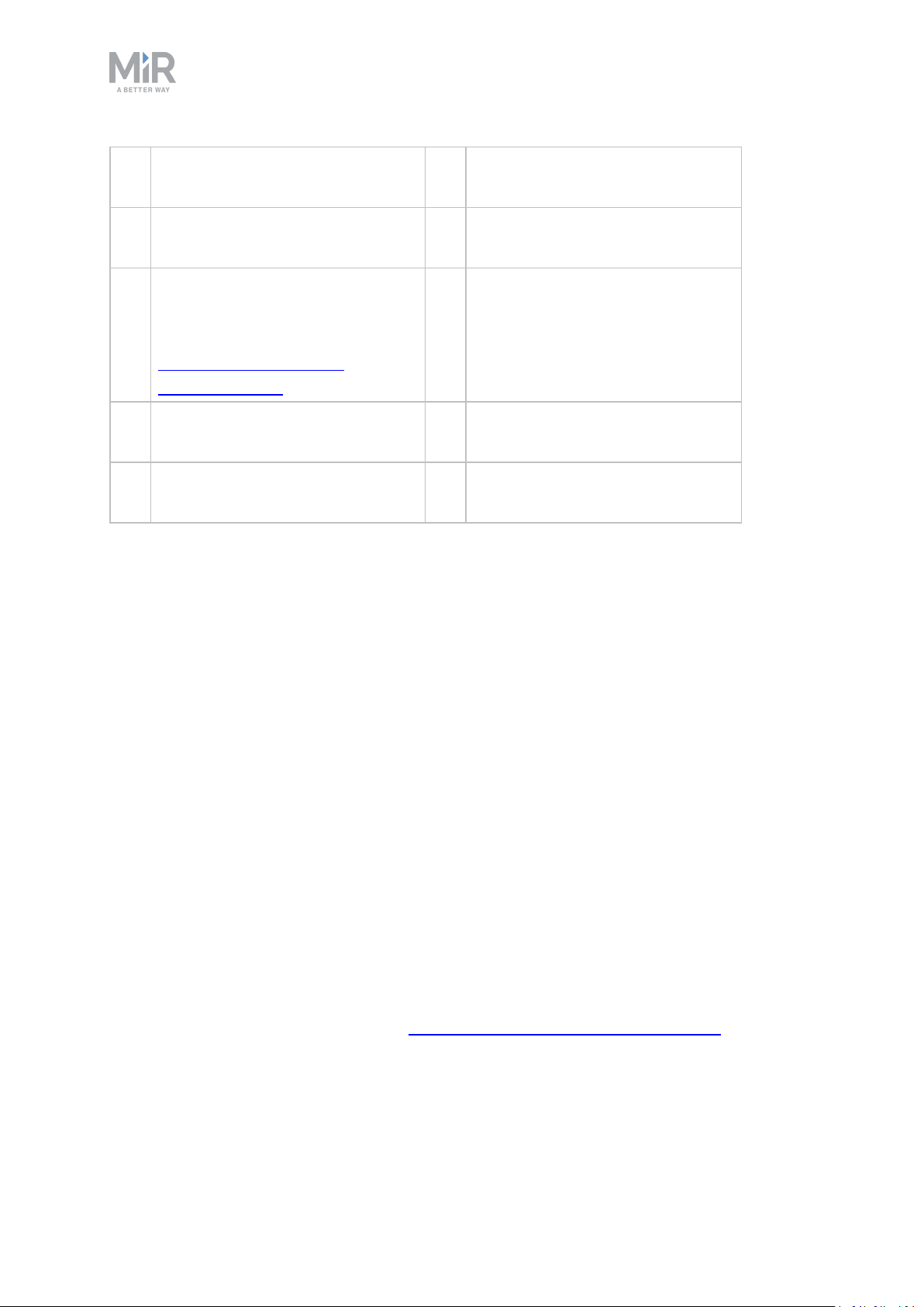
5. Product presentation
5. Battery connector for extra
battery
6. Safe torque off relay (controlled
by SICK)
7. CAN bus connection for Battery
Management System, logging
data e.g. no of charge cycles. See
MiR Robot Interface 2.0
Reference guide.
8. Router - local network, 2.4 and 5
GHz
9. Battery with connector - main
power to the robot
MiR200 internal parts
5.5. Sensor system
14. 24 V power supply - secures stable
voltage for PC and PLC
15. Latching relay - activates the 24V
power supply turning on the robot
16. Transient protection - provides
circuit protection for the power
supplies by absorbing voltage
spikes from battery or top
mounted applications
17. DFI Computer
Collaboration between the robot’s internal and external sensors ensures that the robot can
navigate in the environment and most importantly secures that it can operate safely among
people and objects, like furniture, machines, pallets etc.
This section describes the functionality of the different parts of the sensor system.
Safety laser scanners
The safety laser scanners on MiR200 are of the type SICK S300. In this guide, the term safety
laser scanner is used.
Scanner functions
Two safety laser scanners, diagonally placed on front and rear corners of the robot, scan
their surroundings. Each safety laser scanner has a 360° field of view up to 1 meter around
the robot, providing visual protection around the robot.
The safety laser scanners serve three purposes:
• They are used for mapping, see also MiR Robot Interface 2.0 Reference Guide.
• They are used to localize the robot in the environment and plan routes between points.
MiR200 User guide (en) 09/2019 - v.1.4 ©Co pyright 2019: Mobile Industrial Robo ts A/S. 35
Page 36
5. Product presentation
• They continuously scan the surroundings when the robot operates, thereby avoiding col-
lision with objects and people.
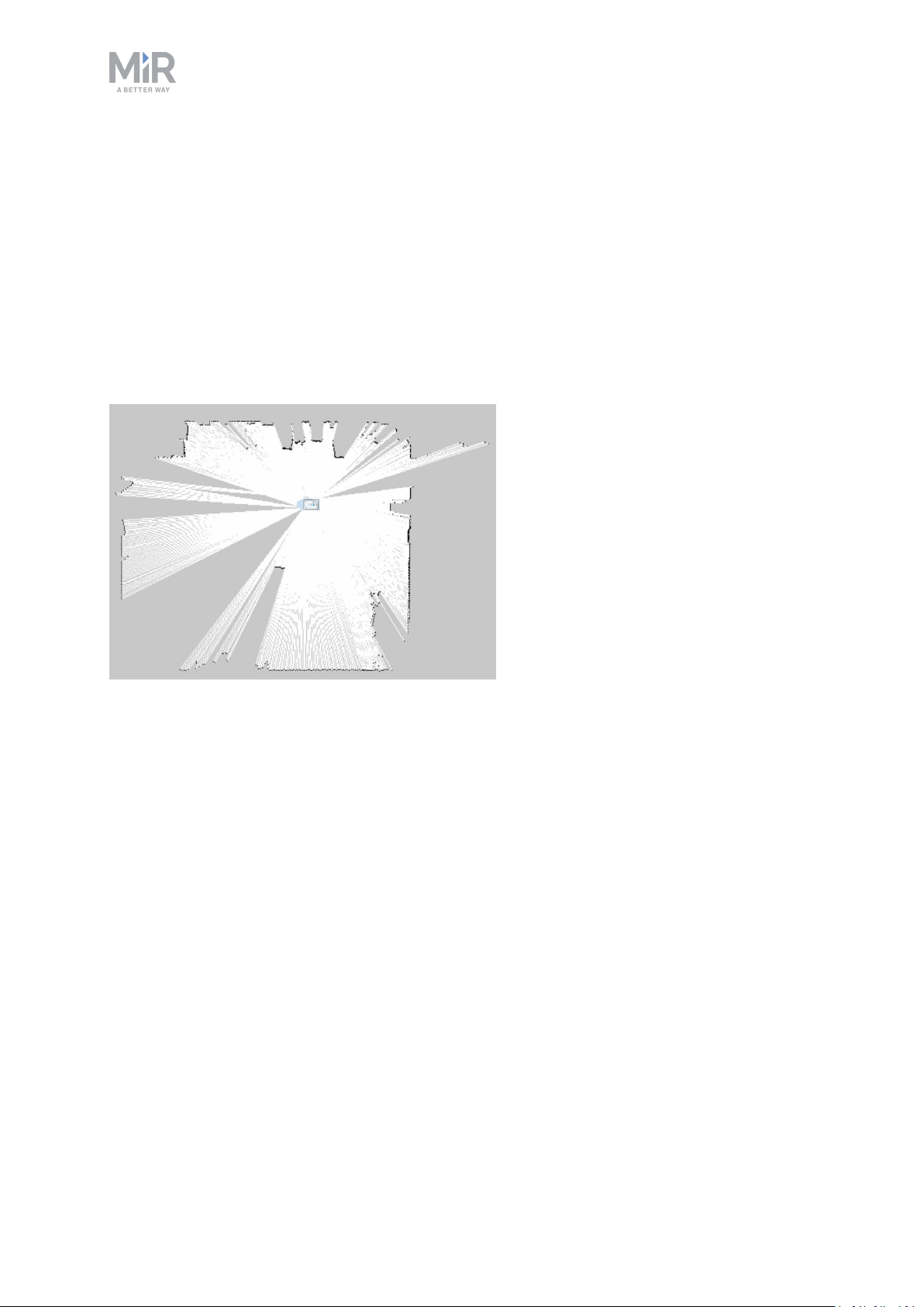
The safety laser scanners detect objects in a plane approximately 200 mm above ground.
Objects above or below are not detected by the safety laser scanners.
When in motion, the safety laser scanners continuously scan the surroundings using a
distance of up to 2.5 m.
When mapping, the safety laser scanner’s view is reduced to 20 m to support that maps will
get the highest possible quality.
The safety laser scanners see up to 20 m when mapping an area.
Signals from safety laser scanners are combined with input from 3D cameras and proximity
sensors and used to evaluate if an object or person is in the path of travel. In that case, the
robot gradually slows down while trying to avoid the obstacle. If unable to make its way
around the obstacle, the robot stops and waits for clearance.
Protective field sets
The protective field sets are part of the robot’s personnel detection means. The protective
field sets consist of individually configured contours around the robot. MiR200 activates the
correct field set based on the speed. If a person or object within the area active protective
field set, the robot will do a protective stop and remain stopped until the protective field set
is free.
The following tables show the sizes of the protective fields sets at given speeds. The faster
the robot moves, the larger the scanners' field set.
The protective field sets differ for forwards and backwards driving.
MiR200 User guide (en) 09/2019 - v.1.4 ©Co pyright 2019: Mobile Industrial Robo ts A/S. 36
Page 37
5. Product presentation
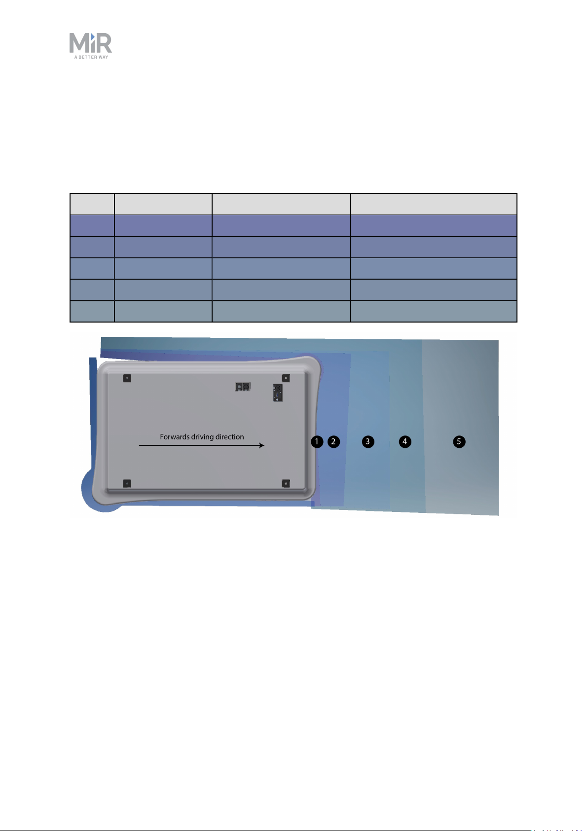
Field sets for forwards driving direction
The following table shows speeds and field sets in forwards driving direction. The table
describes the length of the field set in front of the robot in different cases. Each case is
defined by a speed interval that the robot may operate at. The colors and cases in the table
correspond to the field set shown in the illustration below.
Case Speed Field set in front of robot Comments
1 -1.40 to 0.20 m/s 20 mm Reversing and slowly forwards
2 0.21 to 0.40 n/s 120 mm
3 0.41 to 0.80 m/s 290 mm
4 0.81 to 1.10 m/s 430 mm
5 1.11 to 2.00 m/s 720 mm Forwards at max. speed
The illustration shows the field set contours in forwards driving direction. The reach of the
field set changes with the robot's speed. In Case 1 the field set reaches 20 mm ahead, in Case
2 it reaches 120 mm ahead etc.
MiR200 User guide (en) 09/2019 - v.1.4 ©Co pyright 2019: Mobile Industrial Robo ts A/S. 37
Page 38
5. Product presentation
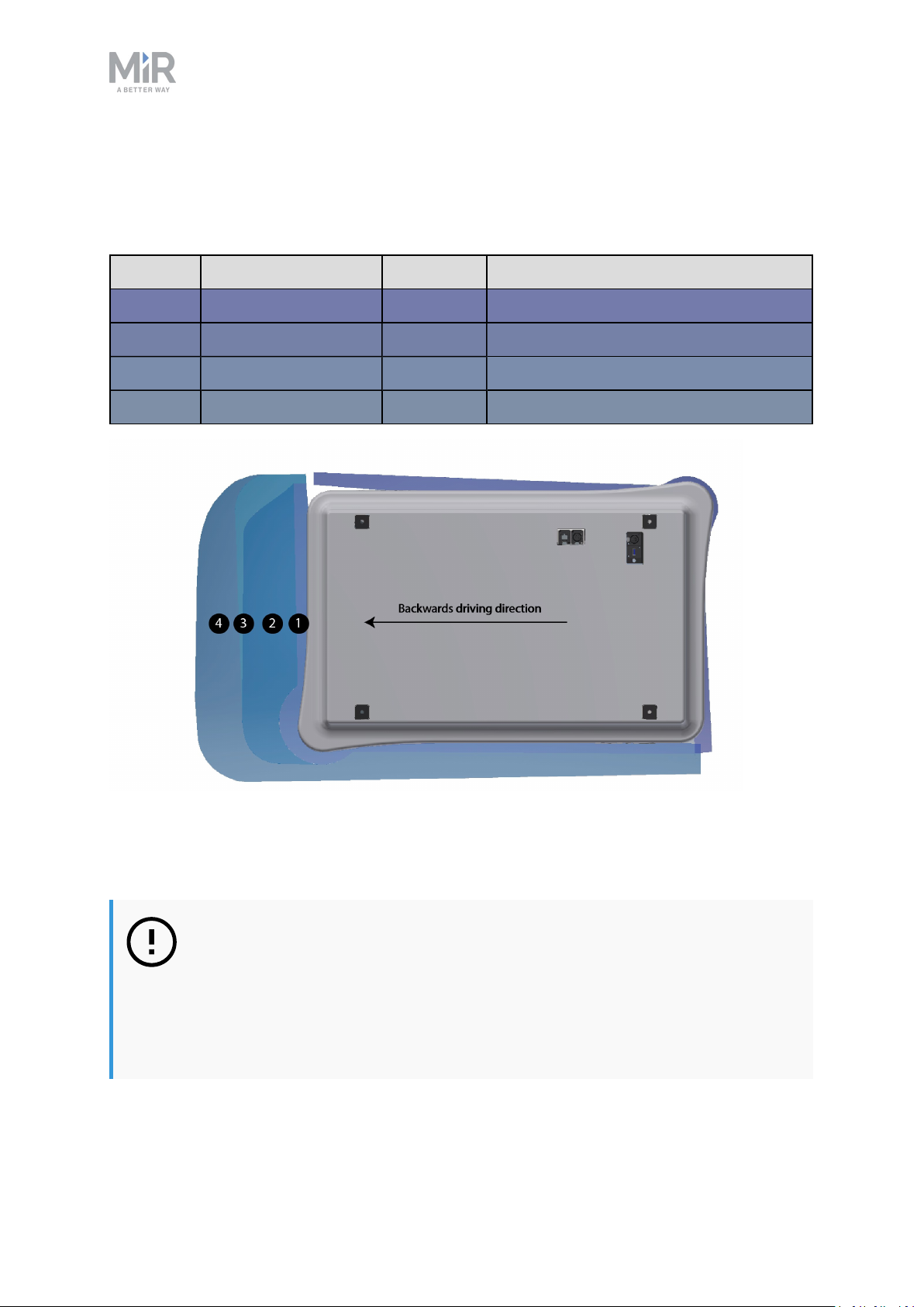
Field sets for backwards driving direction
This table shows speeds and field sets in backwards driving direction. The colors correspond
to the field set shown in the illustration below.
Case Speed Field set Comments
1 -1.14 to 1.80 m/s 30 mm Reversing and slowly backwards
2 -0.20 to 0.15 m/s 120 mm
3 0.40 to 0.21 m/s 290 mm
4 -1.50 to 0.41 m/s 430 mm Backwards at max. speed
The illustration shows the field set contours in backwards driving direction. The reach of the
field set changes with the robot's speed. The illustration also shows how the front scanner
reduces its protective field sets to a minimum when the robot moves backwards.
NOTICE
Protective field tolerances
Scanners measure distances to diffuse reflections which means that a
tolerance is added to the protective field sets to secure a safe detection of
persons crossing the protective field sets. The tolerance distance is 100 mm.
MiR200 User guide (en) 09/2019 - v.1.4 ©Co pyright 2019: Mobile Industrial Robo ts A/S. 38
Page 39
5. Product presentation
CAUTION
The protective field sets are configured to comply with the safety standards of
MiR200.
If they are changed, Mobile Industrial Robots takes no responsibility for any
safety related incidents, and the warranty becomes void.
3D cameras
Two 3D depth cameras positioned on the front of the robot detect objects in front of the
robot while the robot’s local planner continuously adjusts its planned routes around such
objects.
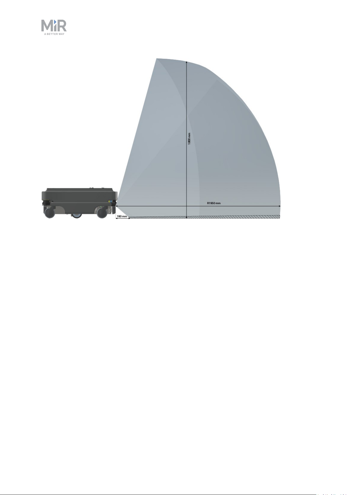
The 3D cameras detect objects:
• Vertically up to 1800 mm at a distance of 1950 mm in front of the robot.
• Horizontally 180 mm to the first view of ground.
The 3D cameras do not detect objects within 50 mm of the lenses.
The space from the floor and vertically up to 50 mm is ignored. This space increases by 10
mm for every one meter horizontally.
The camera readouts are used as 3D point cloud data. They are not recording
recognizable objects or people.
The following illustrations show the field of view of the cameras.
MiR200 User guide (en) 09/2019 - v.1.4 ©Co pyright 2019: Mobile Industrial Robo ts A/S. 39
Page 40
5. Product presentation
The two 3D cameras can see objects up to 1800 mm above floor height.
MiR200 User guide (en) 09/2019 - v.1.4 ©Co pyright 2019: Mobile Industrial Robo ts A/S. 40
Page 41
5. Product presentation
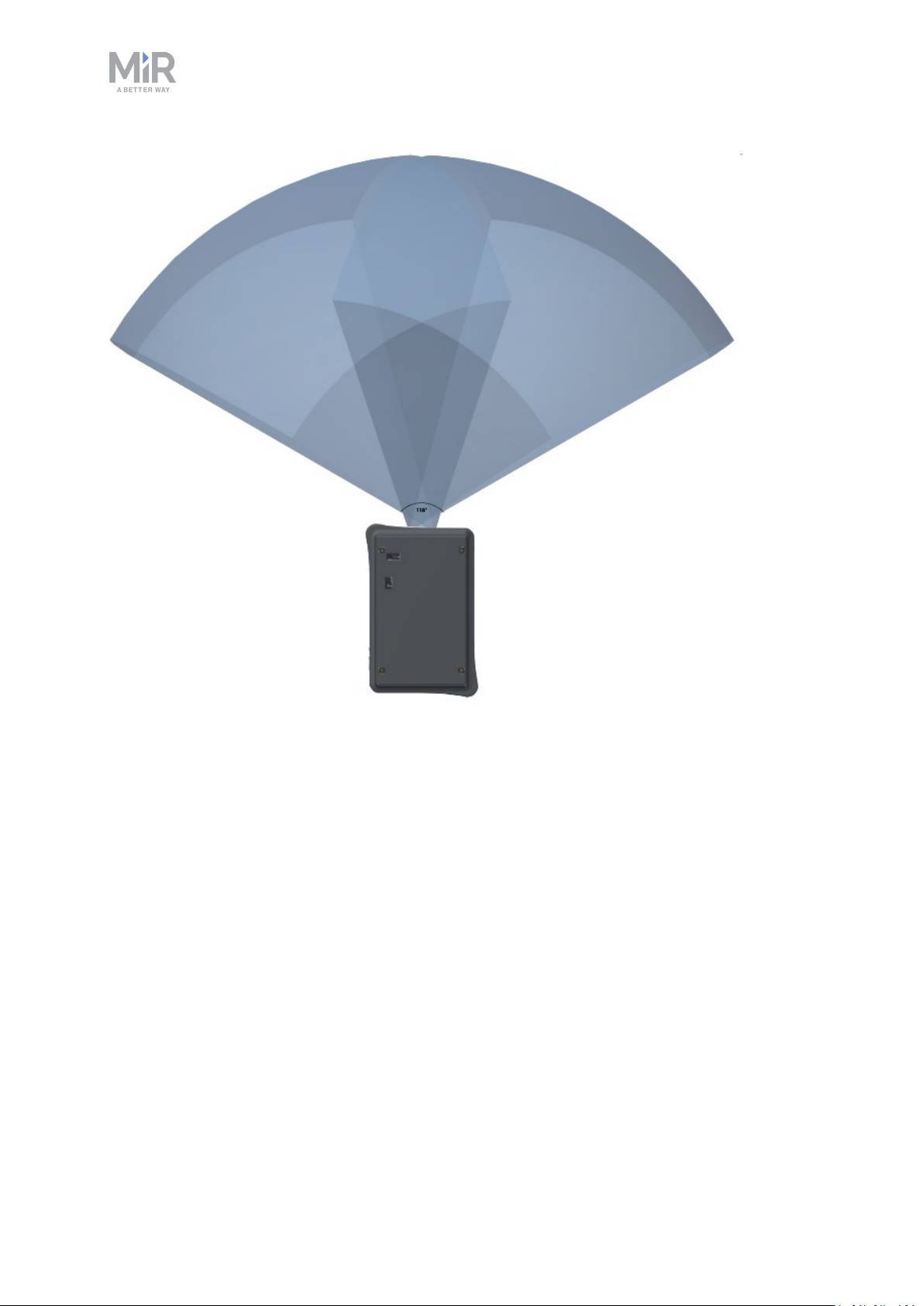
The two 3D cameras have a horizontal field of view of 118°.
Ultrasound sensors
Four ultrasound sensors are placed on the robot: two at the front and two at the rear of the
robot. The ultrasound sensors are used to detect transparent objects.
Internal sensors
The internal sensor system of the robot consists of the following components:
• Gyroscope (IMU)
Measures the orientation and angular velocity of the robot.
• Motor encoder
Provides closed loop feedback signals by tracking the speed and/or position of the motor
shaft.
• Accelerometer
Measures non-gravitational acceleration.
MiR200 User guide (en) 09/2019 - v.1.4 ©Co pyright 2019: Mobile Industrial Robo ts A/S. 41
Page 42
5. Product presentation
• Wheel encoders
Detect wheel movements.
5.6. Light indicators
The robot uses light indicators to let people in the environment know what the robot is
currently doing.
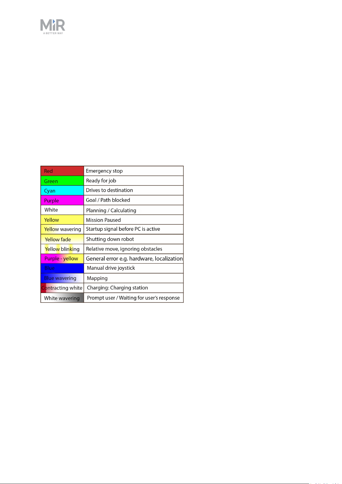
Status lights
The LED light band running all the way around the robot indicates the robot’s current
operational state. Colors may also be used as part of missions, but as standard, the robot is
delivered with the following setup.
Status lights show the current operational state on MiR200
MiR200 User guide (en) 09/2019 - v.1.4 ©Co pyright 2019: Mobile Industrial Robo ts A/S. 42
Page 43
6. Maintenance
6. Maintenance
The following maintenance schedules give an overview of regular cleaning and parts
replacement procedures.
The stated intervals are indicative and depend on the operating environment
and frequency of usage of the robot.
NOTICE
Only use approved spare parts.
Mobile Industrial Robots disclaims any and all liability if unapproved spare
parts are used. Mobile Industrial Robots can not be held responsible for any
damages caused to the robot, accessories or any other equipment due to use
of unapproved spare parts.
6.1. Regular weekly checks and maintenance tasks
Once a week, carry out the following maintenance tasks:
Parts Maintenance tasks
Robot cover and
sides
Clean the robot on the outside with a damp cloth.
Do not use compressed air.
MiR200 User guide (en) 09/2019 - v.1.4 ©Co pyright 2019: Mobile Industrial Robo ts A/S. 43
Page 44
6. Maintenance
Parts Maintenance tasks
Laser scanners Clean the optics covers of the scanners for optimum performance.
Avoid aggressive or abrasive cleaning agents.
Clean the laser scanners using a damp cloth, or for better
maintenance see the notice below. Also do this before contacting
your local technical support with any of the issues mentioned below.
We recommend cleaning the laser scanners daily to increase the
chance of avoiding these issues.
Possible problems from not cleaning the laser scanners:
• The robot fails to detect markers / pallet racks
• The robot goes into emergency stop without obvious reason
NOTICE
Static charges cause dust particles to be attracted to
the optics cover. You can diminish this effect by using
the anti-static plastic cleaner (SICK part no. 5600006)
and the SICK lens cloth (part no. 4003353). See the
manufacturer’s own documentation.
Caster wheels (the
four corner wheels)
Drive wheels (the
two middle wheels)
Remove dirt with a damp cloth, and make sure nothing is entangled
in the wheels.
Remove dirt with a damp cloth, and make sure nothing is entangled
in the wheels.
LED light band Check if the LED light band is intact. Ensure that the light shows all
the way around the robot.
6.2. Regular checks and replacements
Before starting replacement tasks that involve removal of the top cover:
• Press the On/Off button to turn off the robot
• Push the battery switch button to remove power from the battery
• Turn off relays and unplug the battery
MiR200 User guide (en) 09/2019 - v.1.4 ©Co pyright 2019: Mobile Industrial Robo ts A/S. 44
Page 45
6. Maintenance
The following table contains the parts that you should check and the intervals when you
should do that:
Part Maintenance Interval
Robot cover Check for cracks.
Check mounting. Does it sit evenly
on top of the robot with
connections accessible.
Caster wheels
Check bearings and tighten. Check weekly and replace once a
(the four corner
wheels)
Drive wheels (the
Check wheel surfaces for wear. Check every six months and
two middlewheels)
Check monthly and replace as
needed.
year.
replace as needed.
NOTICE
You must calibrate
the robot after
replacing the
wheels. To do this,
access the robot's
user interface and
navigate to System
> Robot setup. Further instructions
are provided here.
MiR200 User guide (en) 09/2019 - v.1.4 ©Co pyright 2019: Mobile Industrial Robo ts A/S. 45
Page 46
Part Maintenance Interval
6. Maintenance
Scanners Check for visual defects, e.g.
cracks and scratches.
Emergency stop To check that the emergency stop
buttons work, push down the red
button and check that the emer-
gency reset button lights up.
Replace as needed.
NOTICE
You must calibrate
the robot after
replacing the scanners. To do this,
access the robot's
user interface and
navigate to System
> Robot setup. Further instructions
are provided here.
Every three to four months /
according to EN/ISO 13850
Safety of machinery - Emergency
stop function.
3D cameras Check for visual defects, e.g.
cracks and scratches.
Manual brake
release
Check if the brakes can be deac-
tivated. Activate the brakes and
push the robot gently forward.
Remember to deactivate the brake
after testing.
Internal cabling Check if all network/USB cables
are plugged in properly.
Safety marking on
the floor
Check if the safety markings made
with e.g. tape around cart pick-up
and drop-off points are intact and
visible.
Safety stickers Check if the safety stickers on the
robot are still intact and visible.
Check monthly and replace as
needed.
Check monthly and replace as
needed.
Check every six months and
replace as needed.
Check every six months and
replace as needed.
Check every six months and
replace as needed.
MiR200 User guide (en) 09/2019 - v.1.4 ©Co pyright 2019: Mobile Industrial Robo ts A/S. 46
Page 47
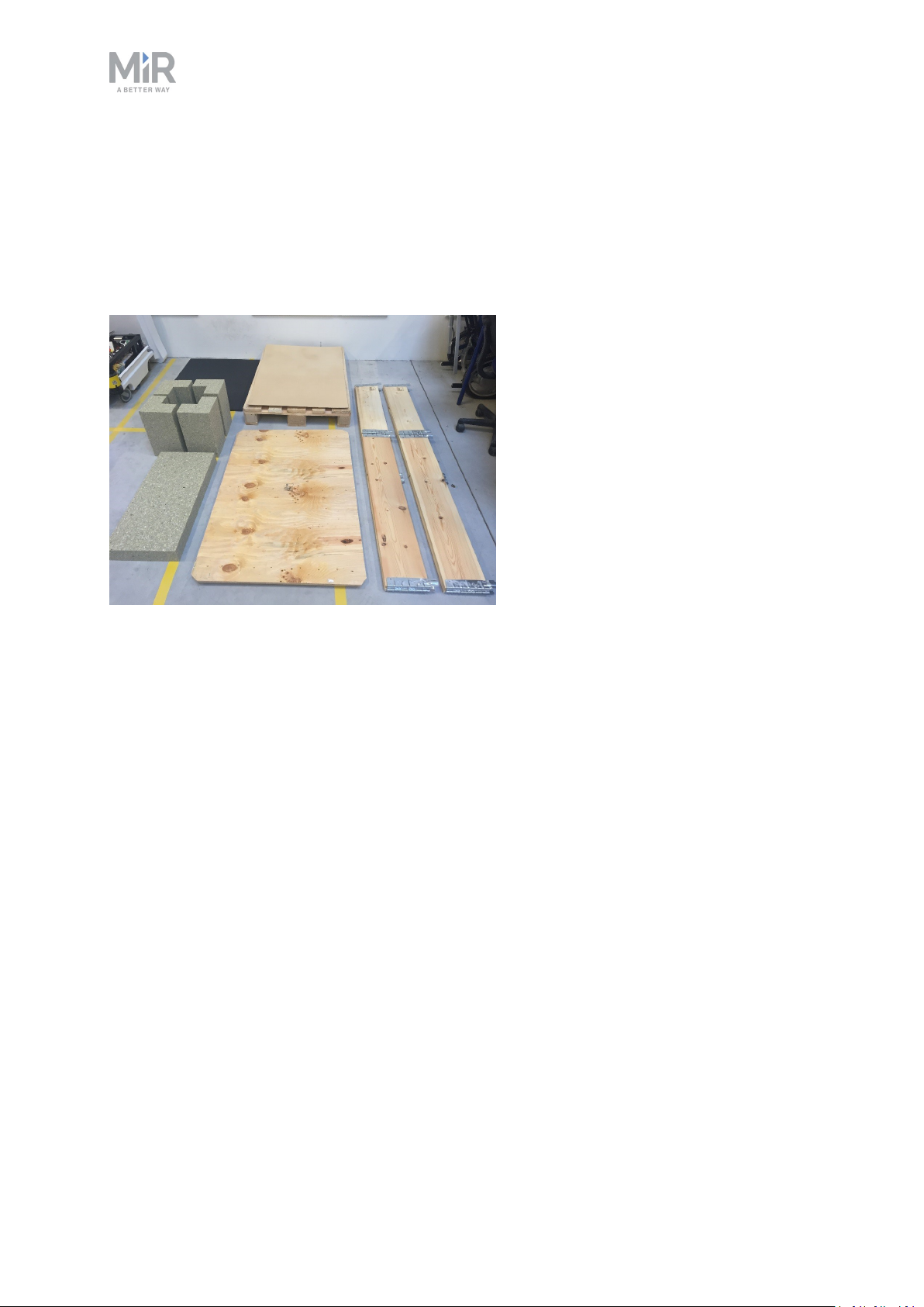
6.3. Packing for transportation
This section describes how to pack the robot for transportation.
Original packaging
Use the original packaging materials when transporting the robot.
6. Maintenance
The packaging materials are:
• The bottom of the box (the pallet).
• The lid of the box (the ramp).
• The walls of the box.
• Protective foam blocks: Side blocks and the top layer.
• Screws.
Packing the robot for transportation
To pack the robot for transportation:
1. Shut down the robot. See section .
2. Turn the battery disconnect switch to position OFF (the two yellow indicators pointing to
off).
Repeat the steps in section Getting started on page15 in the reverse order.
MiR200 User guide (en) 09/2019 - v.1.4 ©Co pyright 2019: Mobile Industrial Robo ts A/S. 47
Page 48
6. Maintenance
NOTICE
Pack and transport the robot in an upright position. Packing and transporting
the robot in any other position voids the warranty.
Battery
The lithium battery is subject to transport regulations. Make sure that you follow the safety
precautions in this section and the instructions in section Packing for transportation on the
previous page. Different regulations apply depending on the mode of transportation: land,
sea, or air.
Contact your distributor for more information.
CAUTION
Lithium batteries are subject to special transportation regulations according to
United Nations Regulation of Dangerous Goods, UN 3171. Special transport
documentation is required to comply with these regulations. This may influence both transport time and costs.
MiR200 User guide (en) 09/2019 - v.1.4 ©Co pyright 2019: Mobile Industrial Robo ts A/S. 48
Page 49
7. Applications
7. Applications
You can install top modules on top of MiR200 for specific applications. For more information
about top modules, go to the following page:
http://www.mobile-industrial-robots.com/en/mir-tradeforum/
For instructions on how to mount top modules and accessories, refer to the application
manuals at www.mir-robots.com or contact your distributor.
7.1. Mounting a top module
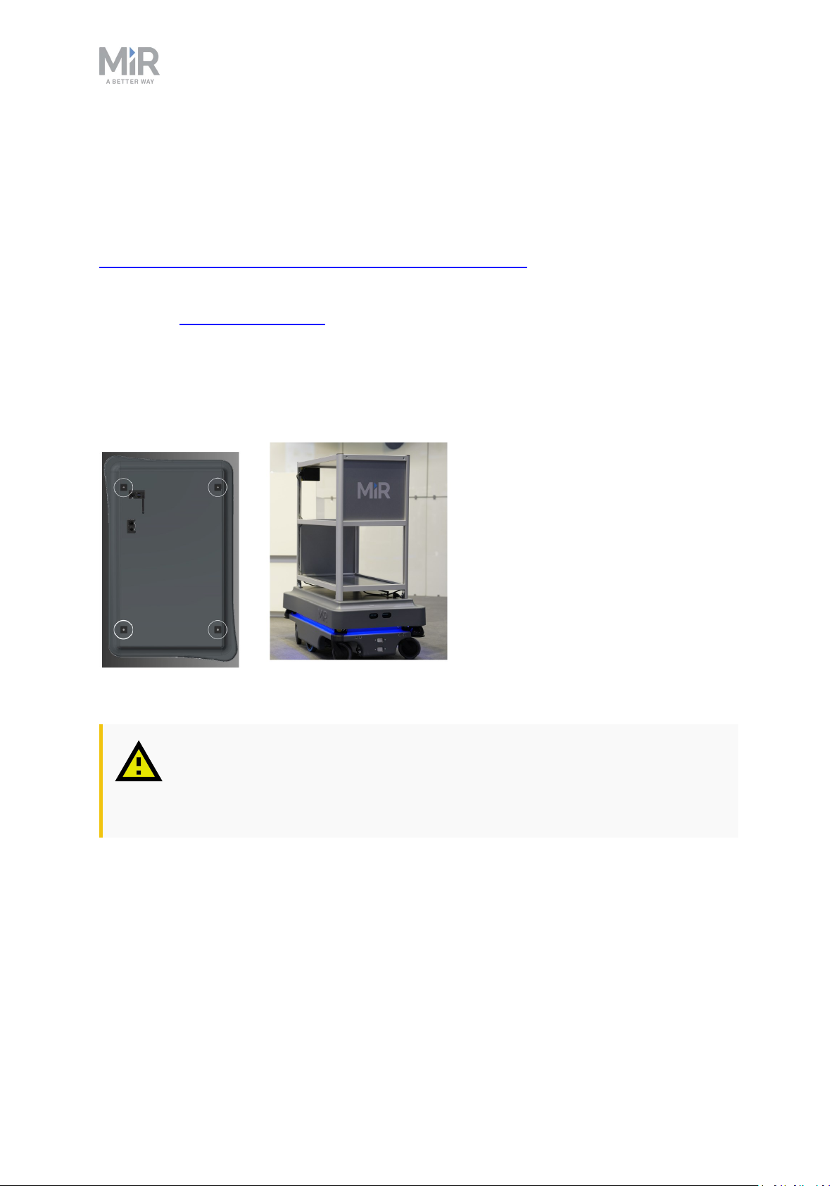
Top modules must be fastened using the self-tightening conically shaped mooring holes in
each corner of the robot and should be mounted with a tightening torque of 47 Nm.
Top modules are fastened through the mooring holes in the top cover.
CAUTION
Certain top modules may require the installation of an extra emergency stop
button. Perform risk assessment according to standard ISO 12100.
MiR200 User guide (en) 09/2019 - v.1.4 ©Co pyright 2019: Mobile Industrial Robo ts A/S. 49
Page 50
7. Applications
CAUTION
Certain top modules may lead to new hazards and/or increased risks which
cannot be eliminated or reduced by the risk reduction measures applied by
Mobile Industrial Robots. Perform risk assessment according to standard ISO
12100.
CAUTION
Stay within the specifications for weight and the payload’s center of gravity,
see Payload specifications on page51.
MiR200 User guide (en) 09/2019 - v.1.4 ©Co pyright 2019: Mobile Industrial Robo ts A/S. 50
Page 51
8. Payload specifications
8. Payload specifications
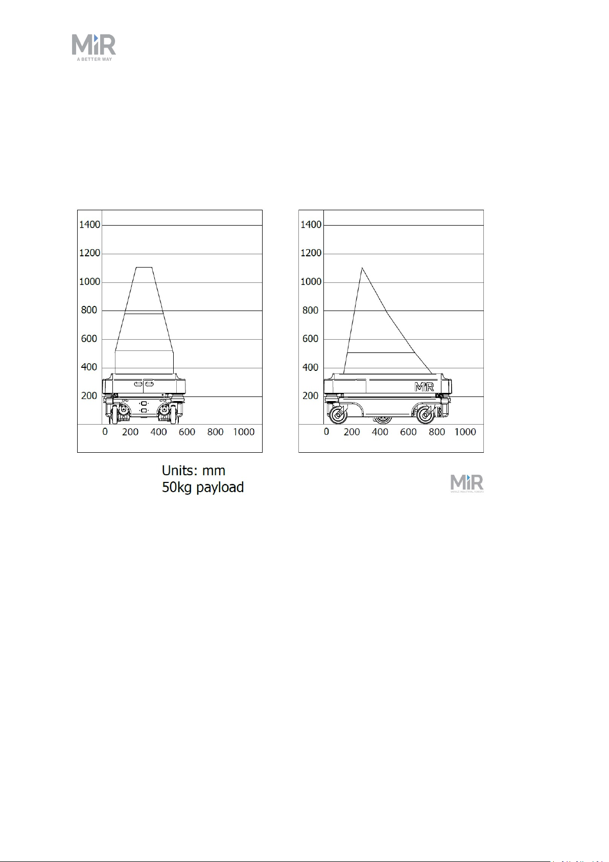
The following drawings illustrate the center of mass (CoM) specifications for safe operation
at different payloads.
Payload: 50 kg
MiR200 User guide (en) 09/2019 - v.1.4 ©Co pyright 2019: Mobile Industrial Robo ts A/S. 51
Page 52
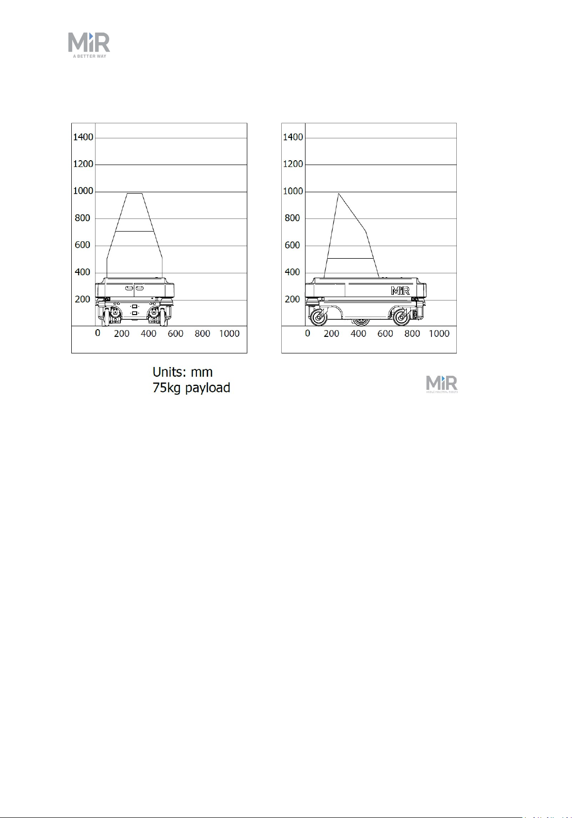
Payload: 75 kg
8. Payload specifications
MiR200 User guide (en) 09/2019 - v.1.4 ©Co pyright 2019: Mobile Industrial Robo ts A/S. 52
Page 53
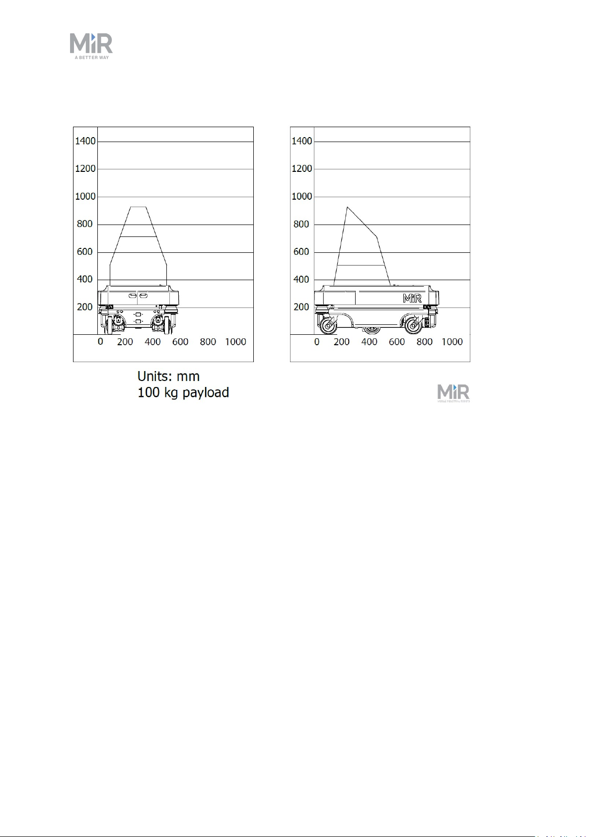
Payload: 100 kg
8. Payload specifications
MiR200 User guide (en) 09/2019 - v.1.4 ©Co pyright 2019: Mobile Industrial Robo ts A/S. 53
Page 54
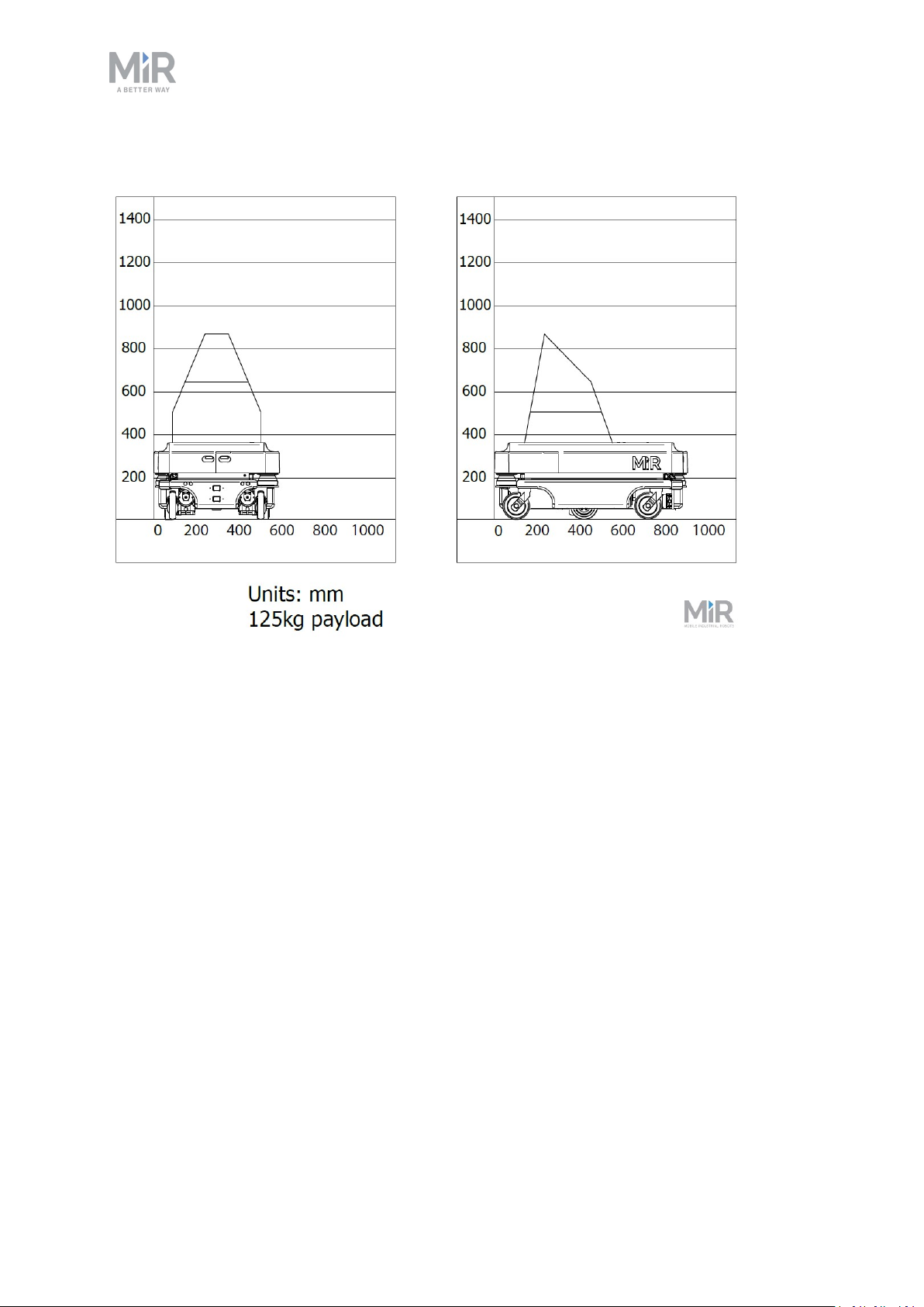
Payload: 125 kg
8. Payload specifications
MiR200 User guide (en) 09/2019 - v.1.4 ©Co pyright 2019: Mobile Industrial Robo ts A/S. 54
Page 55
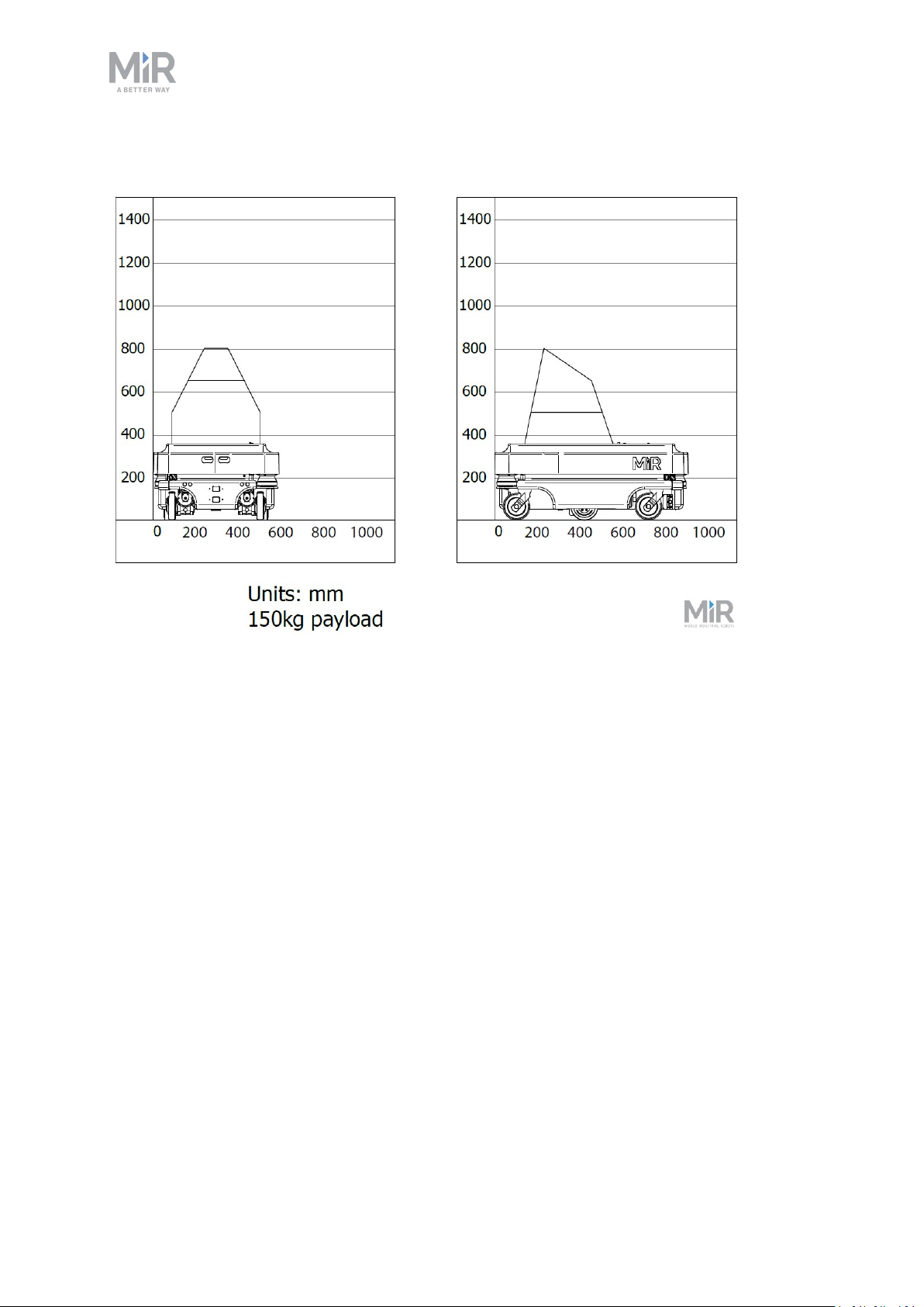
Payload: 150 kg
8. Payload specifications
MiR200 User guide (en) 09/2019 - v.1.4 ©Co pyright 2019: Mobile Industrial Robo ts A/S. 55
Page 56
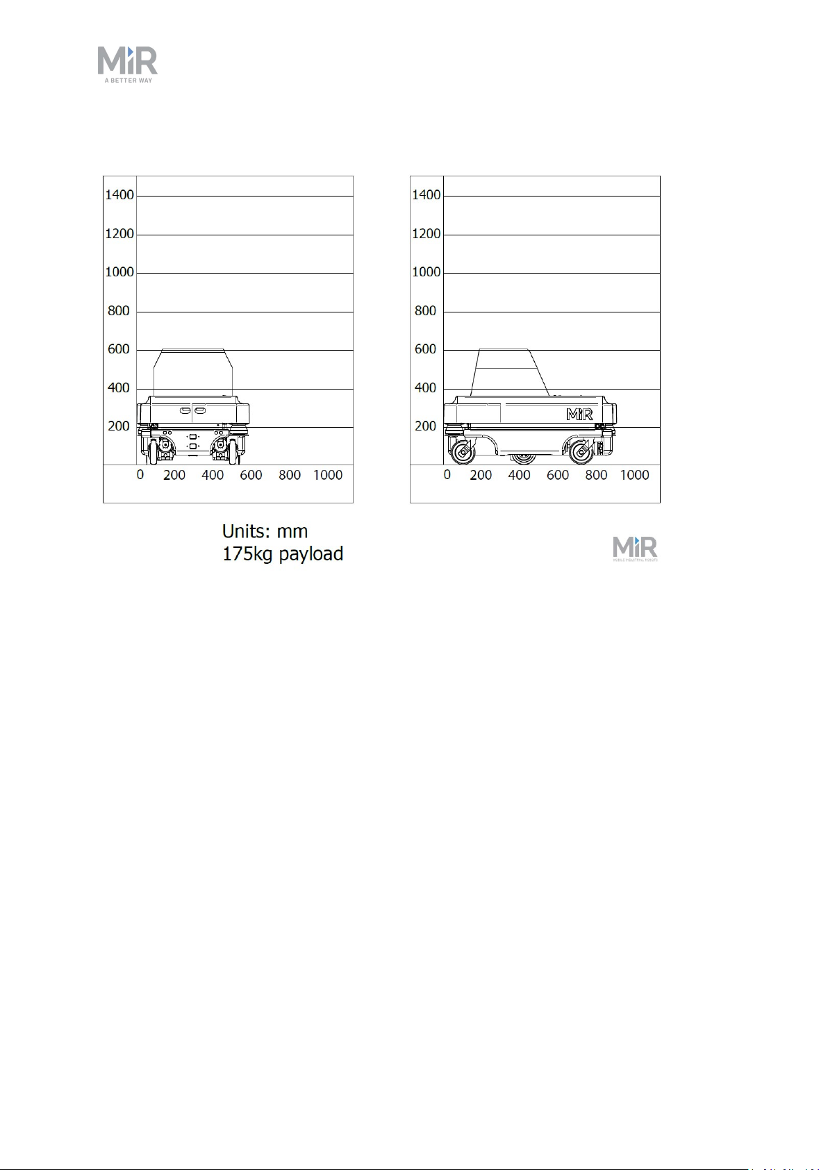
Payload: 175 kg
8. Payload specifications
MiR200 User guide (en) 09/2019 - v.1.4 ©Co pyright 2019: Mobile Industrial Robo ts A/S. 56
Page 57
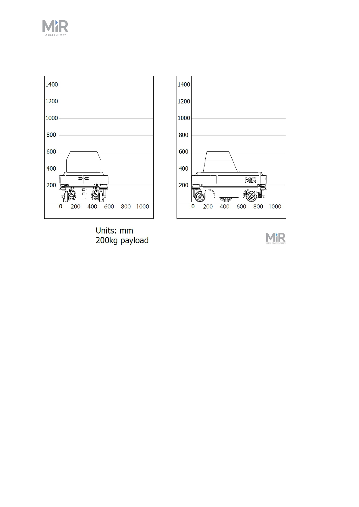
Payload: 200 kg
8. Payload specifications
MiR200 User guide (en) 09/2019 - v.1.4 ©Co pyright 2019: Mobile Industrial Robo ts A/S. 57
Page 58
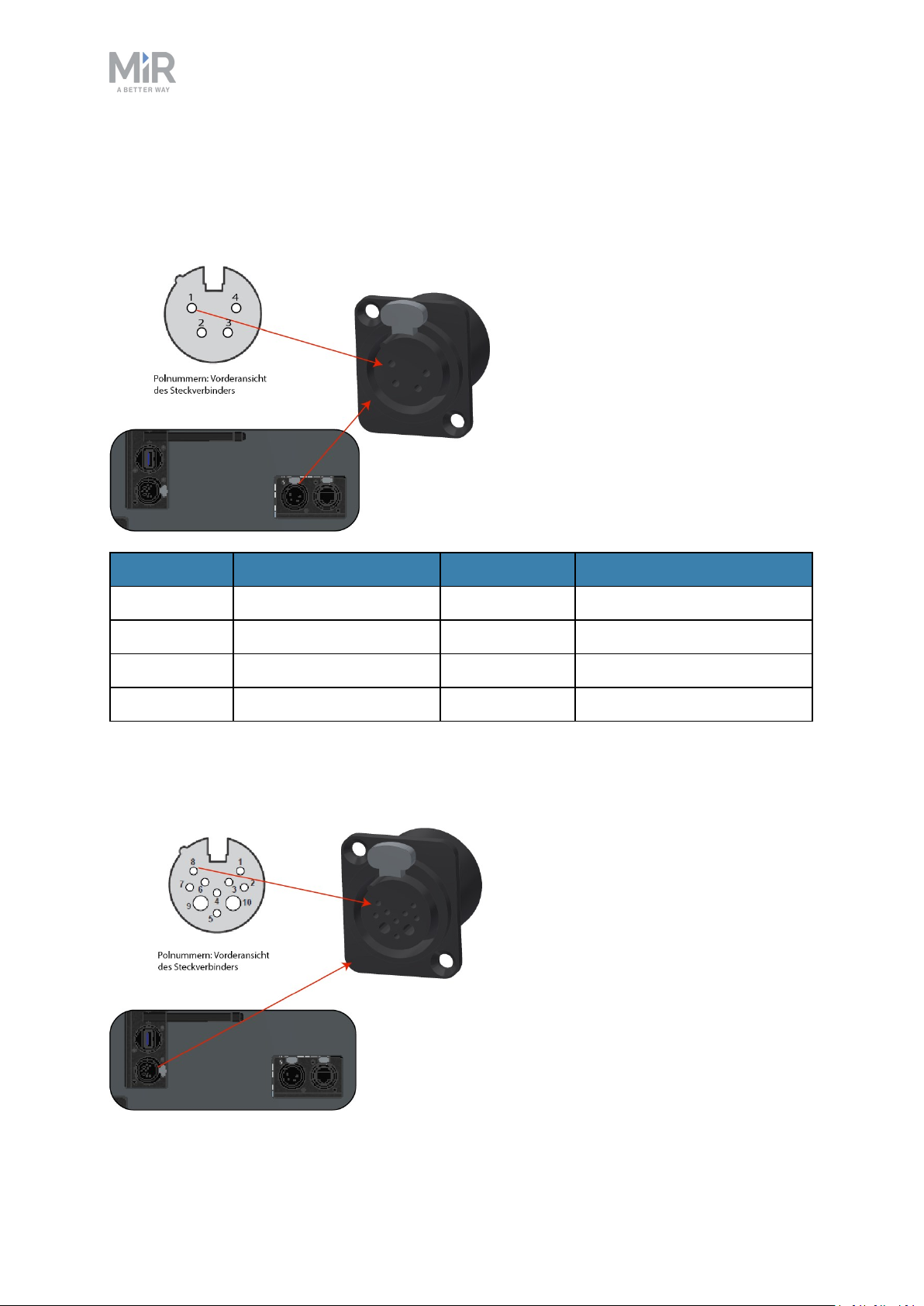
9. Interface specifications
9.1. Application interface
9. Interface specifications
Pin number Voltage Max. current Description
1 Battery voltage (24 V) 3A Starts with the robot.
2 Battery voltage (24 V) 3A Starts with the robot.
3 Battery voltage (24 V) 10A Stops by emergency stop.
4 GND 10A Ground.
Application interface
9.2. Emergency stop
MiR200 User guide (en) 09/2019 - v.1.4 ©Co pyright 2019: Mobile Industrial Robo ts A/S. 58
Page 59
9. Interface specifications
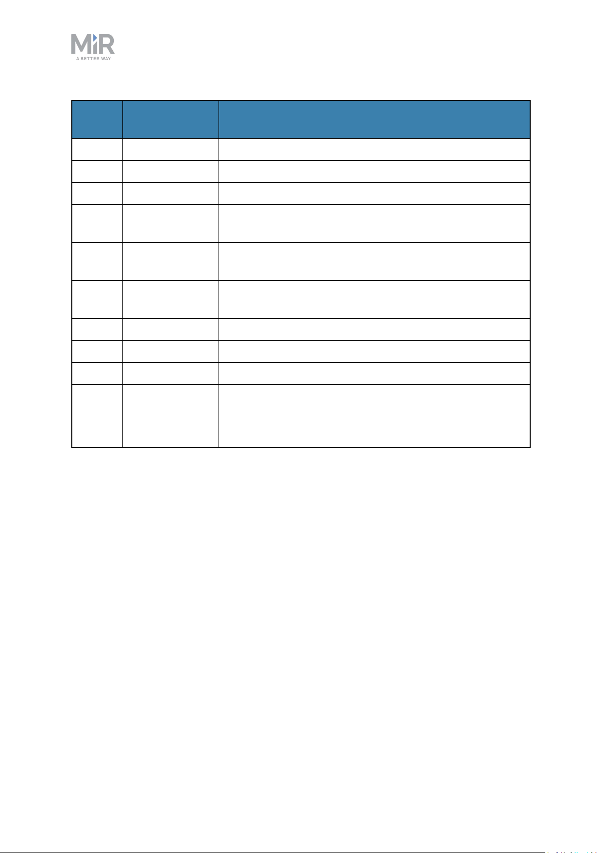
Pin
number
Signal name Description
1 DIN 19
2 DIN 14
3 DIN 70
4 Emergency stop,
1 GN
5 Emergency stop,
GN-WH/RD
6 Reset button,
BWN-WH
7 SICK XTIO, Q3 For SICK scanner
8 I5 For SICK scanner
9 GND To use with the 24V signal from pin 10
10 24V max. 1A Can be used to connect small external unitsusing up to 1
amp. such as tablets and PLC interfaces.
Emergency stop interface
Must use the GND from pin 9.
MiR200 User guide (en) 09/2019 - v.1.4 ©Co pyright 2019: Mobile Industrial Robo ts A/S. 59
Page 60
10. Updating MiR200 software
10. Updating MiR200 software
Follow the steps below to update MiR200 software:
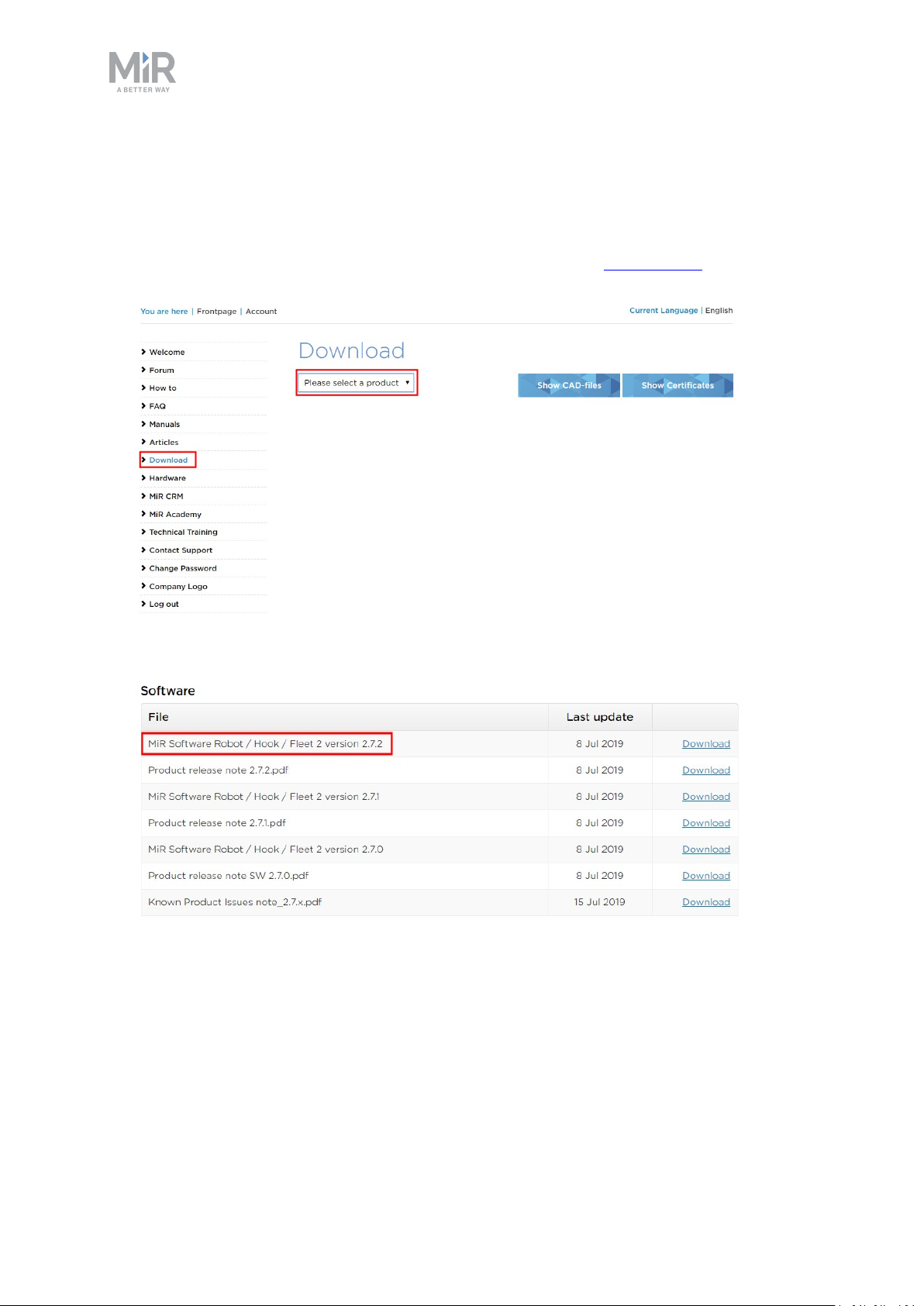
1. Go to MiRDistributor site and sign in with your credentials at mirfleet.com.
2. Select Download and select MiR200 in the product drop down menu.
3. Download the latest version of MiR Software Robot /Hook /Fleet 2 version x.x.x.
4. Connect your computer to the WiFi of the robot you would like to update.
5. Access the robot's interface by going to the website mir.com in your preferred web
browser and sign in.
MiR200 User guide (en) 09/2019 - v.1.4 ©Co pyright 2019: Mobile Industrial Robo ts A/S. 60
Page 61
10. Updating MiR200 software
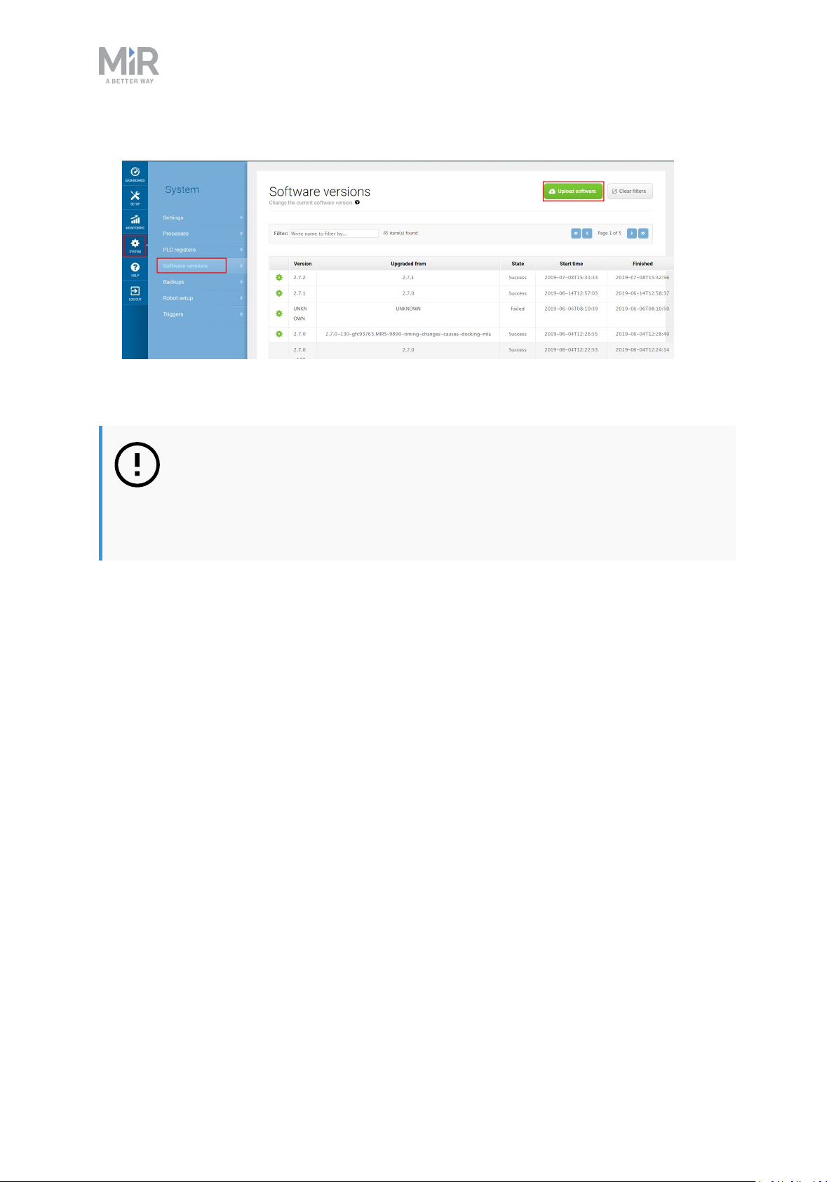
6. Navigate to System > Software versions and select Upload software
7. Locate and select the downloaded software package.
8. It may take a few minutes for the package to successfully upload.
NOTICE
When updating MiR200 with an attached MiRHook 200, the Hook software
must be updated first to ensure that the robot is compatible with the hook
when uploading the software.
MiR200 User guide (en) 09/2019 - v.1.4 ©Co pyright 2019: Mobile Industrial Robo ts A/S. 61
 Loading...