

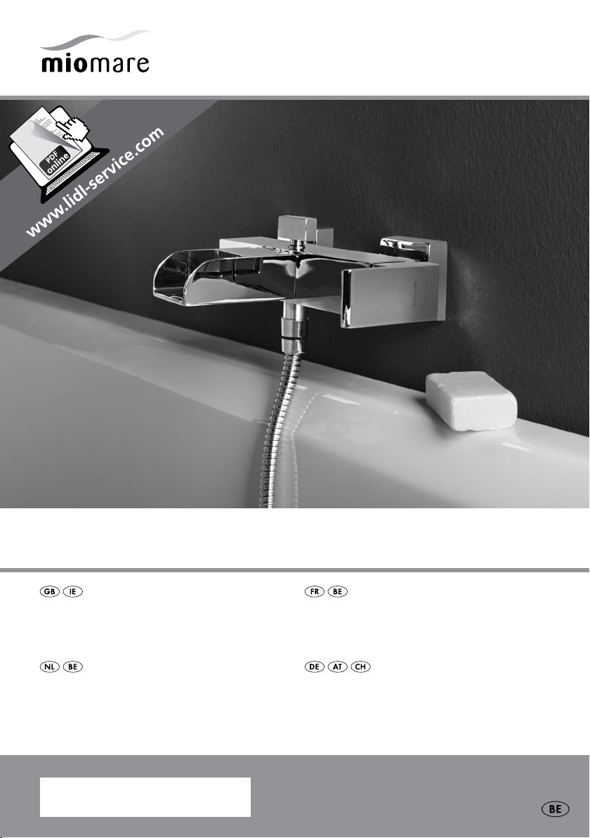
LED Bath / ShowEr Fitting
LED Bath / ShowEr Fitting
Assembly, operating and safety instructions
LED-BaDvuLkraan- /
SproEiEr-armatuur
Montage-, bedienings- en veiligheidsinstructies
IAN 9 1 066
roBinEttEriE DE
BaignoirE / DouchE à LED
Instructions de montage, d‘utilisation et consignes de sécurité
LED-wannEnFüLL- /
BrauSE-armatur
Montage-, Bedienungs- und Sicherheitshinweise
Before reading, unfold the page containing the illustrations and familiarise yourself with all functions of the
device.
Avant de lire le mode d‘emploi, ouvrez la page contenant les illustrations et familiarisez-vous ensuite avec
toutes les fonctions de l‘appareil.
Vouw vóór het lezen de pagina met de afbeeldingen open en maak u vertrouwd met alle functies van het
apparaat.
Klappen Sie vor dem Lesen die Seite mit den Abbildungen aus und machen Sie sich anschließend mit allen
Funktionen des Produkts vertraut.
GB / IE Assembly, operating and safety instructions Page 5
FR / BE Instructions de montage, d‘utilisation et consignes de sécurité Page 13
NL / BE Montage-, bedienings- en veiligheidsinstructies Pagina 21
DE / AT / CH Montage-, Bedienungs- und Sicherheitshinweise Seite 29
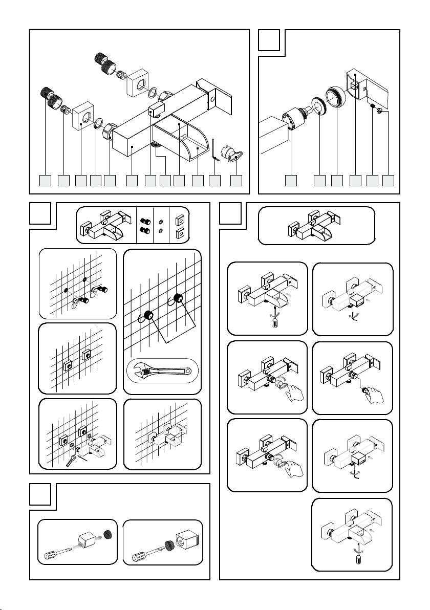
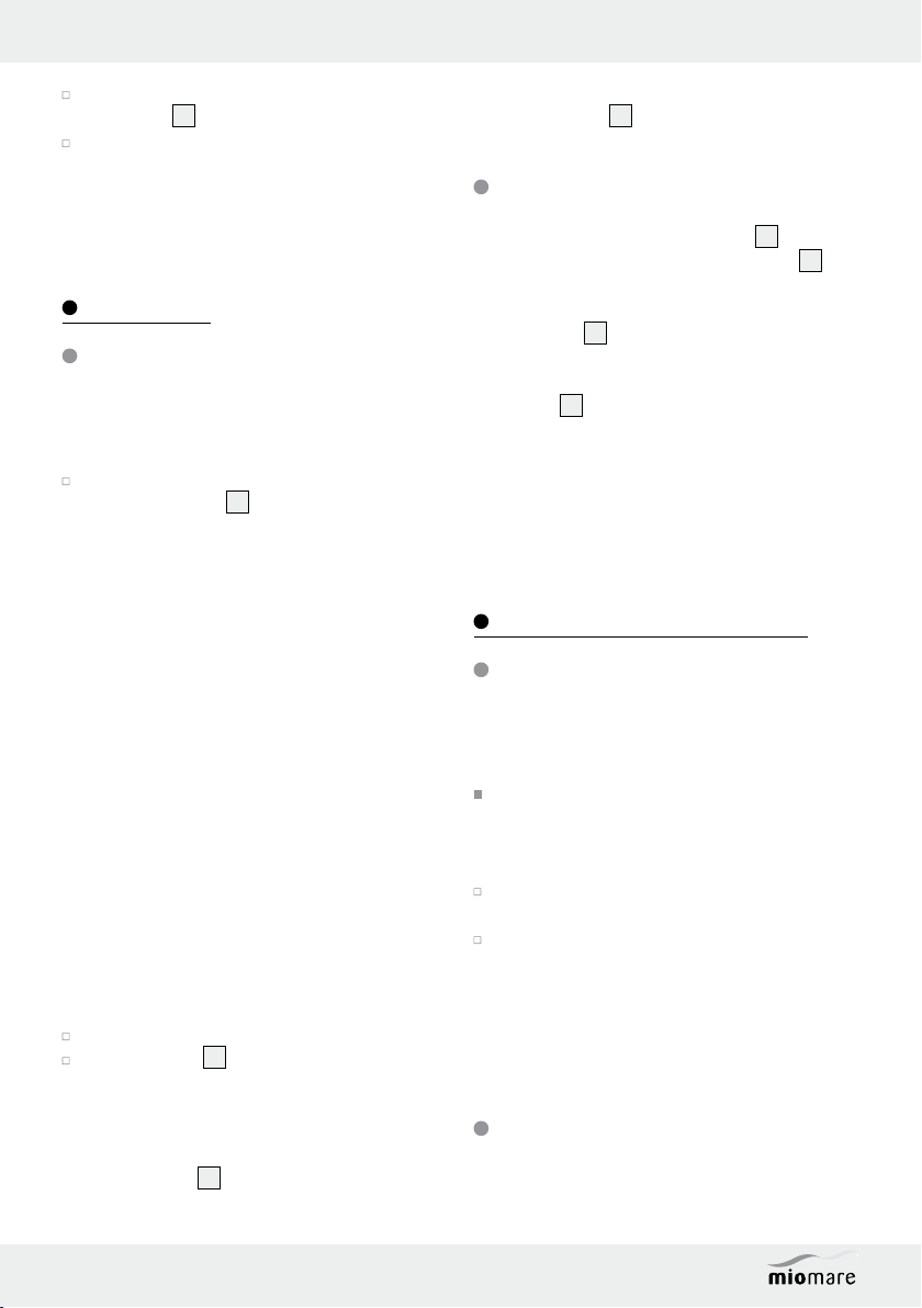
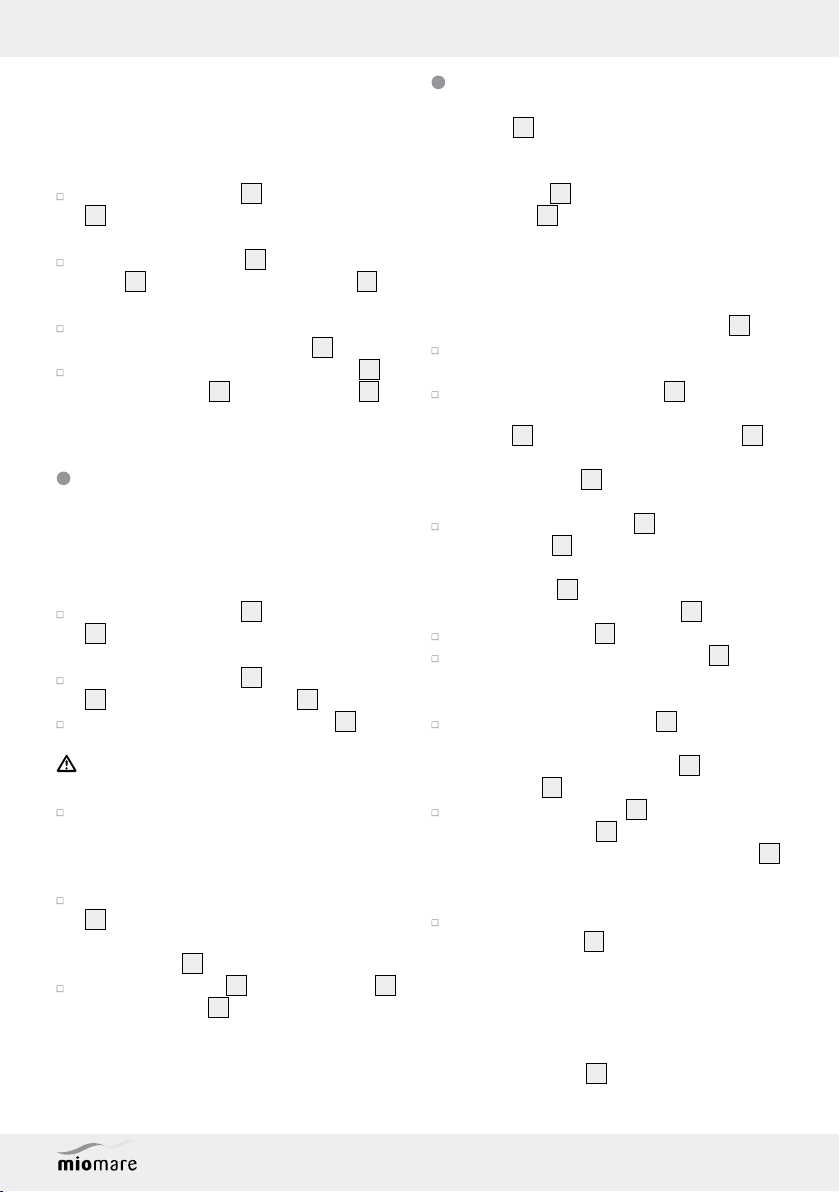
A
B1
B3
B4
B5
150mm
B2
C1
C2
C3
C4
C5
C6
C7
1 2 3 4 5 6 7 8 9 10 1211 13 1817161514
B
D
C
D1 D2


Table of Contents
Introduction
Intended use ........................................................................................................................................ Page 6
Parts description .................................................................................................................................. Page 6
Technical Data ....................................................................................................................................Page 6
Scope of delivery ................................................................................................................................ Page 6
Safety information .................................................................................................................. Page 7
Installation
Connecting the fitting .......................................................................................................................... Page 7
Connecting accessories (shower hose and shower head) ............................................................... Page 7
Operation
Start-up ................................................................................................................................................. Page 8
Tub filler / shower diverter ..................................................................................................................Page 8
Maintenance and Cleaning
Maintaining and cleaning the tap .....................................................................................................Page 8
Replacing the LED insert .....................................................................................................................Page 8
Replacing the screen ........................................................................................................................... Page 9
Replacing the cartridge ......................................................................................................................Page 9
Disposal ............................................................................................................................................ Page 10
Information
Potability of tap water ......................................................................................................................... Page 10
Warranty and Service .......................................................................................................... Page 10
5 GB/IE
Introduction
LED Bath / Shower Fitting
Introduction
Congratulations on the purchase of your
new product. You have selected a high
quality product. The assembly and operating instructions are part of this product. Please
carefully read these assembly instructions / instructions for use before use and observe all instructions.
These assembly instructions and instructions for use
contains important assembly, set-up and care information. Please retain these assembly instructions /
instructions for use and hand them on to any future
owner.
Intended use
The product is only designed to regulate the hot and
cold water flow. For tub installation only. Suitable
for use with all pressure-resistant hot water systems
such as central heating, continuous-flow water heater,
pressure boiler etc. This product is not suitable for
low pressure water heaters or pressure-free small
storage reservoirs, e.g. wood- or coal-burning domestic hot water heaters, oil or gas-fired hot water
heaters, or open electrically heated cylinders. When
in doubt please consult a plumber or heating specialist. Any use not specified or product modification
is prohibited and will result in damage. Any form of
use other than the stipulated intended purpose can
cause danger to life and cause injury. The product is
for private use only and is not intended for medical
or commercial use. The manufacturer accepts no
responsibility if the intended purpose of this unit is
not adhered to.
6
Fitting body
7
Diverter*
8
Shower connection*
9
LED cover*
10
Tub mixer*
11
Socket head wrench
12
LED installation wrench
13
Cartridge*
14
Cartridge lock nut*
15
Cartridge cover ring*
16
Handle*
17
Locking screw*
18
Hot / cold plaque*
* prefitted
Technical Data
Swivel nut
(water connections): G ¾“
Shower hose
connection: G ½“
Flow rate at 3 bar:
Shower connection: approx. 17.7 to 18.8 L / min
Tub mixer: approx. 8.5 to 9.2 L / min
LED light: approx. < 33°C blue,
approx. 33–43°C green,
approx. > 43°C red
approx. > 53°C flashing red
LED life: approx. 10,000 operating
hours
Temperature sensor
tolerance: +/- 2°C
Scope of delivery
Parts description
1
2 S-connectors
2
2 Silencers*
3
2 Covers
4
2 Seals (S-connectors)
5
2 Swivel nuts*
6 GB/IE
1 LED tub filling / shower mixer (5 – 10, 13 – 18)
2 Caps
3
2 S-connectors with silencer (1 – 2)
2 Seals
1 Socket head wrench
1 LED installation spanner
4
11
12
1 Instructions for assembly / operation
Safety information
DANGER TO
LIFE AND RISK OF ACCIDENTS
FOR INFANTS AND CHILDREN!
Never leave children unattended with the packaging material. Danger of suffocation. Keep this
product well away from children. This product
is not a toy.
BEWARE OF ELECTRIC SHOCK!
Leaking or water discharge can lead
to life-threatening danger due to
electric shock. Carefully check that all connections are watertight. Also ensure that all wires
of electric appliances are correct and have
been securely installed.
CAUTION! RISK OF INJURY! Please ensure
that no parts are damaged and that all parts
are correctly assembled. Incorrect assembly
could lead to injury. Please note that washers
and gaskets are wear parts and therefore will
need to be replaced from time to time. Damaged parts could impact safety and function.
CAUTION! DAMAGE TO THE ARTICLE!
Please have all installations performed by skilled
individuals.
Be sure all seals are correctly seated.
SCALDING RISK! When adjusting the hot
water temperature be sure the water temperature is not too high.
CAUTION! Be careful not to revere the hot /
cold water plaque
left = red (hot),
right = blue (cold).
Please note all seals are wear items and will
therefore need to be replaced over time.
Any leakage or sudden escape of water can
cause considerable damage to buildings and
property. All connections must therefore be
checked carefully to ensure that they are tight.
Familiarise yourself prior to installation with all
local conditions, e.g. water connections and
shut-off device.
The product is only suitable for use in rooms
with a temperature above 0 °C.
18
. The correct placement is:
Safety information / Installation
Installation
Note: Familiarise yourself with the product prior to
assembly. Carefully read the following assembly
instructions and safety advice. In the event of incorrect installation, all warranty claims – particularly
in relation to subsequent damage – are excluded.
CAUTION! Before you start installation turn
off the water supply at the mains. Otherwise
injuries and / or property damage may occur.
Connecting the fitting
Note: this step requires an SW 30 mm open-end
spanner and sealing tape.
Note: cover any parts which will be screwed with
a damp cloth or plastic clamps. This will prevent
scratches.
Follow these steps:
Wrap sealing tape around the roughened
threaded part (½“ thread) of the S-connectors
1
(see Fig. B1).
Note: sealing tape not included.
Screw the S-connectors 1 with the sealed
threaded parts into the wall connectors.
Horizontally align the screwed in S-connectors
1
with the spacing guide for the fitting (see
Fig. B2).
Screw the caps 3 hand tight onto the S-con-
1
nectors
Insert the seals 4 into the swivel nuts 5 and
screw the fitting body
onto the S-connectors
Connecting accessories (shower
hose and shower head)
Note: Shower hose and shower head are not
included in delivery.
Note: cover each of the parts which are to be
screw connected with a damp cloth or plastic clips.
This will prevent scratches.
to the wall (see Fig. B3).
6
with swivel nuts 5
1
(see Fig. B4-B5).
7 GB/IE
Installation / Operation / Maintenance and Cleaning
Connect a standard shower hose to the shower
connector
Connect a standard shower head to the
shower hose.
Note: Also refer to the assembly instructions for
the accessories.
8
.
Operation
Start-up
After the initial commissioning, carefully check all
connections for leaks.
Check the operation of the fitting. To do so,
swing the handle
tions.
Note: the fitting features an LED light. The LED is lit
through an integrated turbine (without batteries). The
LED colour changes automatically based on the water
temperature through an integrated temperature
sensor:
· up to approx. 33°C blue,
· from approx. 33-43°C green,
· over approx. 43°C red.
Note: over approx. 53°C the LED light will begin
to flash red to warn of potential scalding.
Note: when starting the fitting for the first time the
LEDs will first flash blue, green and red before indicating the temperature based on the temperature
(self-test).
Note: If the tap has not been used for a long period, flush the pipes thoroughly to avoid stagnation
and build-up of residue.
Open the main water supply.
Lift the handle 16 and swing it to the right or
left in order to regulate the speed or temperature of the water.
Hot water:
Swing the handle
16
into all permissible posi-
16
to the left.
Cold water:
Swing the handle
16
to the right.
Tub filler / shower diverter
Manually switch between the tub filler 10 to shower
function by lifting and lowering the diverter
Tub mixer:
Lower diverter
Shower function:
Lift diverter
Note: switching manually means: when turning
the water off with the shower function activated, the
shower function will remain on. When starting the
water again, the shower function will remain active
until it is switched to tub filler.
7
.
7
.
7
.
Maintenance and Cleaning
Maintaining and
cleaning the tap
Please note that sanitary taps require special care
and attention. Therefore, please follow the instructions:
When cleaning, never use petrol, solvents,
aggressive cleansers or hard cleaning brushes
etc. These could damage the surface of the
product.
Dry your fitting with a cloth after every use to
prevent any lime deposits.
Clean the product with a damp, soft cloth and
a mild cleaning agent if required.
Non-observance of the above care advice can be
expected to result in damage to the surfaces of the
product. This will inevitably invalidate the guarantee.
Replacing the LED insert
If the LED lamps fail to light, the LED insert may be
replaced.
8 GB/IE
Maintenance and Cleaning
LED life: approx. 10,000 operating hours.
A new LED insert (ET-WCRL-LED) can be obtained
from the specified service address.
To do so, follow these steps:
Unscrew the tub mixer 10 from the fitting body
6
(see Fig. C1), which requires a cross-tip
screwdriver.
Unscrew the LED cover 9 from the fitting
6
body
using the socket head wrench 11
(see Fig. C2).
Remove the plastic LED insert (see Fig. C3–C4)
using the LED installation wrench
12
.
Install the new LED insert, the LED cover 9
and the tub mixer
10
to the fitting body 6
similar to disassembly (see Fig. C5–C7).
Replacing the screen
If the screen inside the LED cover is severely clogged
it must be cleaned or replaced.
To do so, follow these steps:
Unscrew the tub mixer 10 from the fitting body
6
(see Fig. C1), which requires a cross-tip
screwdriver.
Unscrew the LED cover 9 from the fitting body
6
using the socket head wrench 11 (see Fig. C2).
Push the screen out of the LED cover 9 from
the outside, using a flat object (see Fig. D1).
CAUTION RISK OF INJURY! The outer
edge of the screen fabric may be pointy.
Remove any limescale deposits or foreign bodies.
Replace the screen if severely clogged or dam-
aged. A new screen (ET-WCRL-WBS) can be
obtained from the specified service address.
Press the cleaned / new screen into the LED cover
9
from the inside (see Fig. D2).
Note: be sure the screen is properly seated in
the LED cover
Install the LED cover 9 and the tub mixer 10
in the fitting body
(see Fig. C6–C7).
9
.
6
similar to disassembly
Replacing the cartridge
A cartridge 13 is a wear part that needs replacing
according to the hardness and / or degree of contamination of the water. This becomes evident
when the handle
new cartridges
service office.
Note: this step requires an open-end spanner
SW 27 mm or fitting pliers.
Proceed as follows to replace the cartridge
Shut off the main water supply. Allow any
remaining water in the pipework to drain.
Remove the hot / cold plaque 18 by inserting a
flat object between the edge of the hot / cold
plaque
Note: use light pressure to carefully push the
hot / cold plaque
scratch the surface.
Loosen the locking screw 17 with the socket
head wrench
CAUTION! Do not completely unscrew the
locking screw
necessary to remove the handle
Remove the handle 16.
Unscrew the cartridge covering ring 15, do not
use pliers or a spanner. Otherwise the product
could be damaged.
Loosen the cartridge locknut 14 below with
fitting pliers or an open-end spanner SW 27 mm
and remove the entire cartridge
fitting body
Insert the new cartridge 13 (model 35 M LED)
into the fitting body
Note: be sure the seal under the cartridge
is correctly seated. Make sure that the guides
are in the corresponding holes.
Reassemble all the above parts. Tighten the
cartridge lock nut
open-end spanner SW 27 mm while simultane-
ously securing the fitting from twisting. This will
achieve tightness and ensure the handle is not
difficult to move.
CAUTION! Be careful not to revere the hot/
cold water plaque
16
becomes difficult to move. A
13
can be obtained from the listed
18
and the outside of the handle 16.
18
outward so as not to
11
by turning it counter-clockwise.
17
. Only loosen this as far as is
16
.
13
from the
6
.
6
in the same manner.
14
using fitting pliers or an
18
. The correct placement is:
13
:
13
9 GB/IE
Maintenance and Cleaning / Disposal / Information / Warranty and Service
left = red (hot water),
right = blue (cold).
Disposal
The packaging is made of environmentally friendly materials, which may be
disposed of through your local recycling
facilities.
Contact your local refuse disposal authority for
more details of how to dispose of your worn-out
product.
Information
Potability of tap water
Please consult your local authorities on the
potability of water in your town / municipality.
The following general recommendations apply to
the potability of tap water:
Let the water run freely for a short time if it has
been stagnating in the pipework for more than
four hours. Do not use any of this stagnant
water in the preparation of food or for drinking.
This applies particularly as far as babies and
infants are concerned. Otherwise health concerns can arise. Fresh water can be readily distinguished from stagnant water as fresh water
is noticeably cooler as it leaves the pipe.
Do not use stagnant water from chromium-plated
pipework to prepare food, for drinking, or for
personal hygiene if you are allergic to nickel.
This water may contain high quantities of nickel
and trigger an allergic reaction.
Do not use water from lead pipework for
preparing food baby food and / or to prepare
foods during pregnancy. Lead dissolves in
drinking water and is particularly damaging to
the health of babies and young children.
Warranty and Service
The warranty period is three years and begins on
the day of purchase. Please keep your receipt as
proof of purchase.
However, if defects do occur during the warranty
period, after first contacting service the defective
fitting may be returned freight forward to the service
address specified. You will then receive a new or
repaired fitting free of charge.
After the warranty period has expired you may also
send the defective fitting to the address specified
for repair. Repairs made after the expiration of the
warranty period are subject to payment.
This warranty does not limit your legal rights.
The warranty period will not be extended by repairs
made under warranty. This applies also to replaced
and exchanged parts. Complaints are often initiated
by difficulties encountered during use. Many of
these complaints can be resolved by telephone or
email. Please contact the service address set up for
you before filing a warranty claim for the fitting
with the manufacturer:
GB:
Eisl Sanitär GmbH
Mattseer Landesstraße 8
A-5101 Bergheim
Tel.: 00800-87934629*
Tel.: +43-662-879346-29
Fax: 00800-87934650*
Fax: +43-662-879346-50
E-Mail: service@eisl.at
* Free of charge number
IE:
Eisl Sanitär GmbH
Mattseer Landesstraße 8
A-5101 Bergheim
Tel.: 00800-87934629*
Tel.: +43-662-879346-29
Fax: +43-662-879346-50
E-Mail: service@eisl.at
* Free of charge number
10 GB/IE

Warranty and Service
IAN 91066
Please have the receipt and item number, e.g.
IAN 12345 ready as your proof of purchase when
making an enquiry.
Product description:
LED Bath / Shower Fitting
Eisl Sanitär no.
NI023WCRL-LIDL
11 GB/IE

12
 Loading...