

Page 1

Aquachlor
Salt Water Chlorinator
Owners Manual
ModelStandard and
Self Clean C Series II
Manufactured in Australia By
Monarch Pool Systems
www.monarchpoolsystems.com
Page 2

2
Aquachlor
Salt Chlorinator
Thankyou for purchasing a Quality Aquachlor Pool and Spa Product. Please read all
information in this Manual carefully before installing or operating your AQUACHLOR
SALT CHLORINATOR.
INDEX
Page 2 Packing List
Page 3 Installation Instructions
Page 4 Pre Start Up Procedure
Page 4-5 Operation of Aquachlor System – C and SC Series
Aquachlor Model C (Standard) and SC (Self Clean) series features
Page 5-7 System Control and Warning LED
Optional Features – Time Clock and Light Transformer
Page 7 Maintenance of Power Supply
Page 7-8 Maintenance of Electrolytic Cell
Page 8-10 Day to Day Operation
Stabiliser, pH and Total Alkalinity, Salt Levels, Running
Times
Page 10-11 Chlorine Production, Super – chlorination and
Chlorine Types and Comparisons
Page 11-12 General Information
Page 12 Trouble Shooting
PACKING LIST - Aquachlor C and SC Systems
Included with your C and SC systems are the following items, please check the contents
of the box carefully prior to attempting to install the system:
1. Power Supply
2. Electrolytic Cell Housing
3. Electrolytic Cell – C or SC Series
4. Cell Adaptors (2)
Page 3
3
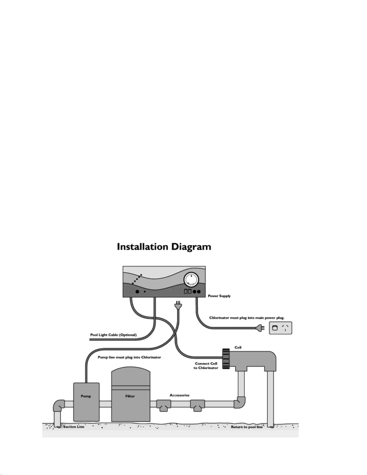
INSTALLATION INSTRUCTIONS FOR AQUACHLOR C and SC
INSTALLING THE POWER SUPPLY:
Select a convenient well-ventilated location within one metre of filter equipment and
mount the Power Supply vertically onto a post or wall 1.5 metres above ground level.
Australian Standards requires that the Power Supply shall not be located within 3 meters
of the pool water. Plug Power supply into a suitable weatherproof outlet and plug pump
into power outlet of the Power Supply Unit. The Unit must be kept away from acid and
other chemical storage areas. Acid and chemical vapours will corrode the electronics
inside the Unit. It must also be kept away from heat sources. Good ventilation is
necessary for correct operation (See diagram at bottom of page). Mount unit via
keyholes on back of Unit.
CONNECTING THE ELECTROLYTIC CELL TO THE POWER SUPPLY:
The Power Supply is fitted with a flexible lead terminated with connector’s. These must
be correctly fitted to the connections on the inside of the Cell Head. To prevent incorrect
connection the fittings have been colour coded. The Blue Flow Sensor should be pushed
onto the thread of the small bolt. The power outlet on the bottom of the Power Supply is
dedicated to the POOL PUMP ONLY. Do not use a double adaptor to connect more than
one pump - it can cause overload to the system and could void your warranty.
Important: The Cell must be installed so that the water flows through the Cell Housing
via the Cell head end in accordance with the arrow on the cell housing. This is to ensure
correct operation of the flow sensor. Refer page 9 for connection of pool light on
optional light transformer models.
Page 4

4
PRE - START UP PROCEDURE:
Before operating your Aquachlor Chlorinator please ensure the following items have
been added to your pool:
• SALT - Load salt into the pool at a minimum rate of 40kg per 10,000 litres (0.4%).
Connect vacuum system and slowly vacuum until salt dispersal is complete. Place
vacuum head into deepest end of pool and allow vacuum to continue for a further 2 or 3
hours. Salt should now be completely mixed.
• CHLORINE - For a new pool installation that has not been chlorinated, add sufficient
Chlorine (liquid or granular) to achieve a reading of 3 ppm (with a suitable test kit), or run
the chlorinator system continuously for at least 24 hours or until a reading of 3 ppm is
reached.
• STABILISER - It is essential that pool stabiliser be added and maintained at the rate
of 30- 50 mg/l (30 - 50 ppm) at all times. Do not exceed 100 ppm.
(Refer Day to Day Operation pages 8-10 for further information).
OPERATION OF AQUACHLOR C (Standard) SYSTEM:
Cell Output is shown on a meter made up of a bar of five LEDs on the left-hand side of
the unit. Normal Cell operation is indicated by at least four LEDs being on. The Unit is
fitted with an electronic control and warning system. This regulates the output of the Unit
to the preset maximum. The warning system consists of an LED which will glow Green
or Red to indicate possible faults with the Unit or damaging operating conditions.
Once the salt level in the pool is correct the Unit may be switched On. The WARNING
LED will be Green and no Cell Output will be seen for approx. 30 seconds, this allows
the pump and filter to prime and the Cell Housing to fill with water. After this start - up
delay the bar meter should light up showing at least four LEDs. At this point the
WARNING LED should be Green; if not there is a problem. (Refer table).
Cell Output Bar
Output Control
Warning LED
Timer
(Optional)
On/Off Switch
& Light Switch
(Optional)
Fuse(s)
Page 5

5
BAR METER
WARNING
LED
REASON/ACTION
Off
Green
1. Start – up delay functioning.
2. System Control set below
max. Cell is turned off. (Refer
System Control page 7).
Off
Red
1. Gas detected. Check
pump/pipes for damage.
2. Gas sensor not connected to
cell
4 or 5 LEDs on
Green
System operating normally
1 to 5 LEDs on
Red
1. Salt level too low. Add salt at
a rate of 25kg per 25000L.
2. Cell is calcified. Clean cell.
3. Water temperature low.
OPERATION OF AQUACHLOR SC SYSTEM:
The Aquachlor SC system operates similarly to the C System described above. The
SC system uses a patented Electronic Self Cleaning system to clean your Cell and
therefore you should not have to clean your SC cell unless you have extreme water
conditions. Note: a Aquachlor SC cell must be used with an SC Unit.
AQUACHLOR MODEL C and SC SERIES SPECIAL FEATURES
SYSTEM CONTROL:
The System Control varies the amount of time the Cell operates during the
filtration cycle.
The System Control will not vary the electrical current supplied to the Cell. (As shown
on the Display).
As an example, if one filtration cycle is set at 5 hours, and the System Control is set to
80%, then the total amount of time the Cell will operate during the 5-hour cycle will be 4
hours. If the System Control is set to 60%, the Cell will operate for 3 hours total over
the 5-hour filtration cycle.
When the System Control is set to MIN, the Cell will be OFF for the duration of the
filtration cycle. When the System Control is set to MAX, the Cell will be ON for the
duration of the filtration cycle.
During the filtration cycle, the Cell will be turned ON and OFF a number of times each
hour, unless the System Control is set at MIN or MAX. Using the previous example (of
60%), the Cell will operate for about 36 minutes each hour. This 36-minute operating
time will be made up of a number of smaller operating periods. As an example, the Cell
may turn ON 12 times (for a period of 3 minutes each time) over the hour to make up the
36 minutes. This enables the electronic circuitry to re - adjust to any changes in the pool
water condition. For example, dilution from winter rains, the addition of salt etc.
Page 6

6
If the Cell is OFF and you wish to check its operation, simply turn the System Control to
MAX and the Cell will turn ON. Once checked, adjust the System Control back to the
desired position and after a few minutes the Cell will turn OFF again.
To turn the Cell OFF, simply turn the System Control to MIN. This will be convenient for
backwashing.
WARNING LED
Your Aquachlor Chlorinator is fitted with a number of protective systems including the
WARNING LED. As the salt level in the pool decreases, the wear on the Cell increases.
Although salt is not consumed in the Aquachlor process, it is lost through splashing,
back - washing and on bathers as they leave the pool. The salt level is also reduced by
rain, which causes dilution. Salt is not lost to evaporation. As the salt level in the pool
falls toward the minimum the WARNING LED will turn RED. At this point the salt level
should be increased by adding 25kg of salt per 25,000 litres of pool water. The addition
of salt should not affect the Aquachlor as it is protected against overloads. If no action
is taken and the salt level continues to fall damage to the system may result.
There are other factors that can cause the Unit not to work correctly:
1. Heavy Rain - can cause very dilute pool water to pass over the Cell due to surface
skimming.
2. Scaled Cell - a scaled Cell will not draw as much electrical current as a clean Cell
when first started.
3. Cold Water - cold pool water reduces the ability of a Cell to carry electrical current.
4. Failing Cell - as the Cell ages there will come a time when the electrical current draw
will drop. This can be compensated for with the addition of extra salt. A Cell is
considered failed when it draws less than 80 % of maximum current. To keep a
failing Cell in operation extra salt can be added. There will come a time when the Cell
will not respond to extra salt. It will then need to be replaced.
Please note that the WARNING LED is not like T.D.S. meters, which are temperature
compensated Scientific Instruments. The accuracy will be within 500ppm salinity and
it is water temperature dependent, just as the Cell is.
Automatic Time Clock Operation (optional)
If your Power Supply is fitted with an automatic time clock (optional) the operating
time(s) can be easily set by pushing the small pins forward or backwards to the
desired operating time(s). The unit comes pre-set for 8 hours operation per day.
MODELS WITH POOL LIGHT TRANSFORMER (optional):
Take off Cover Panel by removing the screws in the cover bottom. Insert the two wires
from your pool light into the Terminal Block provided. It does not matter which side of the
Page 7

7
Terminal Block the coloured wires from your pool light are connected. The Light
Transformer is for use with 12volt pool lights, maximum power is 150Watt.
Please Note: Only one light can be connected to each light transformer. If more than
one light is required please refer to your Aquachlor dealer.
SAFETY NOTICE
IMPORTANT Certain local electrical regulations state “If the supply cord is damaged, it must
be replaced by a special cord available from the manufacturer or its service agent”.
MAINTENANCE OF POWER SUPPLY:
Little or no maintenance is normally required with the exception of replacing blown
Fuses. These 3 Amp Fuses (5amp for C520) can be sourced from your local
Aquachlor Dealer. However it is essential that the wall or post to which the Unit is
installed be sprayed (not the Unit itself) periodically with a good surface type insect
repellent, since penetration by insects may cause damage which is not covered by your
warranty.
The Unit will become warm to hot when in operation, this is normal.
MAINTENANCE OF ELECTROLYTIC CELL:
The cell is composed of extremely expensive materials, and although proper
maintenance can prolong its life to the maximum, eventually the process of electrolysis
will wear away its delicate coating, at which time it gradually ceases to produce chlorine.
Mineral salts and calcium (scale) are deposited on the outer and the inner plates as
electrolysis takes place. This build up will interfere with the flow of electrical current in
the Cell and thus lowers sanitiser production. It is essential to inspect the Cell regularly
and clean when necessary. The rate at which deposits will form on the plates differs
with each pool and can be influenced by the following:
Calcium hardness of the water
Water Temperature
pH control
Water which has been chlorinated with calcium hypochlorite for an extended
period
Calcium in the plaster surfaces of a concrete pool
Because these conditions vary so much, check the Cell at least weekly to begin with to
see when either scale or a blue/green soapy substance appears on the plates. You will
then be able to determine the cleaning cycle necessary for your pool (obviously more in
summer). The intervals between cleaning could get longer to the point where cleaning is
only necessary a few times each year. One exception is the use of bore water or ground
water, in which case cleaning may always need to be as frequent as once a week.
Life of Aquachlor electrolytic cells will vary substantially from one installation to
another due to variations in operating time, water quality and composition, system and
cell maintenance. Please ensure that when cell replacement is necessary you use the
correct genuine Aquachlor replacement cell to match your system.
Page 8

8
Aquachlor C Standard
Aquachlor SC Self Clean
C Standard
Systems Model
C Replacement Cell
Model to order
SC Self Clean
Systems Model
SC Replacement
Cell Model to order
260
260
250
250
390
390
330
330
520
520
SC SYSTEMS Please Note that unless you have extreme water conditions
the Cell should not become scaled and you should not have to clean the
Cell. In areas of extremely hard water it may be necessary to clean your
cell periodically. Refer below.
To clean the cell, remove all leads connected to the Head Assembly. Unscrew the
Cell by turning the Head Assembly clockwise – as per instructions, and withdraw from
the Cell Housing.
METHOD 1
Add 1 part HYDROCHLORIC ACID to 5 parts WATER in a suitable container and
immerse the Cell in this solution. It should not take longer than a few minutes to clean, if
it does the Cell should be cleaned more frequently. If the build – up is not excessive it
may be possible to clean the plate with a jet of running water. Return the Cell to its
Housing and connect leads to the Head Assembly.
METHOD 2
As an alternative, an approved commercial Cell cleaning solution can be used a number
of times effectively.
SAFETY DEVICE:
Hydrogen Gas is a by – product of the chlorine producing process. A Gas Sensor has
been incorporated into the Unit and Cell, which will switch off chlorination if gas is
detected in the Cell Housing or there is no water flow.
Aquachlor Units are also fitted with a Thermal Cut – Out to prevent overheating. If the
temperature rises too high, power is automatically disconnected. The Unit will resume
operation when it cools down.
DAY TO DAY OPERATION:
Four Prime rules must be observed if your unit is to give the best possible service:
1. STABILISER
The importance of pool stabiliser cannot be over – emphasised. It is essential in helping
retain chlorine in your pool. Chlorine is rapidly dissipated by sunlight and the use of
stabiliser will reduce this dissipation substantially. Without stabiliser, it may be
necessary to run the Unit for up to three times as long!
Page 9

9
Stabiliser should be added at the rate of 500 grams for every 10,000 litres of water. To
add, place the required amount in a stocking and tie a brick to it. Place the stocking in
front of the return jet. It will dissolve in 2 – 3 days.
Stabiliser should be maintained at a level of 30 – 50 ppm. Before adding more
stabiliser, have your pool water analysed at your pool shop to ensure that you do not
add too much.
Consult your local Aquachlor Dealer for more information.
2. pH AND TOTAL ALKALINITY:
A correct pH level must be maintained to prevent problems such as black spot, staining,
cloudy water, etc. An incorrect pH level can damage the pool. Correct pH levels are as
follows; Fibreglass – 7.0 to 7.4 Other pools – 7.2 to 7.6 If you allow the pH level to rise to
8.0 or above, the chlorine required could be as much as three times the normal amount.
To lower the pH add HYDROCHLORIC ACID. To raise the pH level add SODIUM
BICARBONATE OR SODA ASH.
Total Alkalinity should not be confused with pH, although the two are closely related.
Total Alkalinity determines the speed and ease of pH change. It is measured in ppm –
the ideal range is 80 – 150 ppm, or refer to your pool professional.
You should use a test kit which includes a test for Total Alkalinity. Low Total Alkalinity
can cause unstable pH levels – i.e. An inability to keep the pH constant may cause
staining, etching and corrosion of metals. High Total Alkalinity will cause constantly high
pH levels.
To lower, add HYDROCHLORIC ACID (a little at a time). To raise, add SODIUM
BICARBONATE.
3. SALT LEVELS:
The salt level MUST NEVER BE LESS THAN 4000 ppm for Aquachlor Systems.
Operating the Unit with too little salt in the pool will cause damage to your Cell. For C
Systems there is no need to exceed 7000 ppm, however, no problems will result if this
occurs. Aquachlor chlorinators can be operated in Seawater, refer to the manufacturer
for details.
Salt is the essential element by which your Unit operates. Not enough salt means not
enough chlorine - this simple rule governs the total operation of your Aquachlor, and
insufficient salt will damage your Cell.
Salt is NOT used up in the process of producing chlorine or by evaporation. Salt is only
lost through back - washing, splash - out, overflow or by leakage from the pool or
plumbing. Winter rains can dilute the salt solution in your pool; therefore salt levels
should be checked during this season. Colder water during Winter will reduce the unit
output and turn the WARNING LED red. If this occurs extra salt can be added or simply
check the salt level regularly and ignore the WARNING LED until water temperatures
rise.
Low salt levels will destroy the coating on the Anode plates and will void all
Warranty.
Page 10

10
The Aquachlor unit has a built in warning system to minimise damage resulting from
insufficient salt levels, however, the ultimate responsibility is on the owner to ensure
adequate salt levels are maintained all year round.
4. RUNNING TIMES:
If you run your chlorinator for 24 hours a day, or for long periods, the Cell life will be
greatly reduced. It is important that the correct model Aquachlor has been installed on
your pool. Many models are available to cope with small courtyard pools up to
commercial applications. (Consult your local Aquachlor Dealer for more information).
CHLORINE PRODUCTION:
The Aquachlor unit must be run daily to generate sufficient chlorine to sanitise the
pool. During Summer this is approximately eight hours per day, preferably in two periods
- between 6.00 and 8.00am and between 5.00 and 11.00pm. Night time is preferable
because chlorine dissipates rapidly in direct sunlight. If these running times are
observed, and the Cell is functioning correctly, your pool will have sufficient chlorine
when tested in the morning. If the level is too low either longer running times are
required or the System Control needs to be adjusted to maximum. Harsh local
conditions such as traffic pollution or windborne dust require different running times, in
which case, seek advice from your pool shop. During Winter approximately 4 to 6 hours
a day should provide enough chlorine. Without sufficient filtration/chlorination, your pool
will never function correctly. ALWAYS RUN THE FILTER WHEN SWIMMING IN THE
POOL. In extremely hot weather or during periods of heavy bathing loads, the running
time may need to be extended to 10 - 14 hours per day.
In some cases you may find your chlorine level to be too high. To determine if this is the
case, run your filter/chlorinator for the suggested times/chlorine production level and test
your pool water on the morning after operation. If your chlorine test shows a high level of
chlorine, either the running times can be reduced slightly, or the System Control can be
turned anti - clockwise. Test your chlorine level again the following morning at around
the same time. If your chlorine level is still high, repeat the above process until the
correct level is attained.
SUPER - CHLORINATION:
Periodically, especially during extremely hot conditions, it may be necessary to boost the
amount of chlorine in your pool in order to maintain absolute sanitation of the water. This
can be achieved by adding either liquid or granulated chlorine. If granulated chlorine is
added, the Cell must be checked regularly, since the additives from this product will clog
the electrodes. Alternatively, extend the running time of your Aquachlor.
CHLORINE TYPES AND COMPARISONS:
Many chlorinator manufacturers calibrate their units to compare with 65% granulated
chlorine, making it necessary to adjust their readings to a lower level in order to
determine true chlorine production. The Display on your Aquachlor expresses
production as pure 100% chlorine so you will know the exact output of your Unit. Below
is a comparison table of the available types of chlorine used to sanitise pools.
Page 11

11
Aquachlor
Model C
(Standard)
Aquachlor
Model SC
(Self Clean)
Productio
n
maximum
grams/hou
r
(100%)
Production
*
grams/hour
(65%
equivalent)
Chlorine
produce
d
over 8
hours
grams
(100%)
Equivalent
in
dry
granulated
chlorine
grams
(65%)
Equivalent
in
liquid
chlorine
litres
(12%)
220
250
16.0
24.6
128
197
1.07
260
20.0
30.8
160
246
1.33
330
25.0
38.5
200
307
1.66
390
30.0
46.0
240
368
2.10
520
40.0
61.5
320
492
2.67
GENERAL INFORMATION:
Algae - Microscopic forms of plant life which enter the pool by rain, wind and dust. There
are numerous varieties - some are free floating whilst others grow on walls and in cracks
and come in different colours. Some are more resistant to chemical treatment than
others.
Bacteria - The germs that contaminate your pool. Introduced by swimmers, dust, rain
storms and other elements.
Balanced Water - The correct ratio of mineral content and pH level that prevents pool
water from being-corrosive or scale forming.
Chloramines - Compounds formed when chlorine combines with nitrogen from urine,
perspiration, etc. Chloramines cause eye and skin irritation, as well as unpleasant
odours.
Chlorine Demand - The chlorine required to destroy germs, algae and other
contaminants in the pool.
Chlorine Residual - The amount of chlorine remaining after chlorine demand has been
satisfied. This is the reading obtained with your test kit.
Cyanuric Acid - Also known as stabiliser or conditioner. It reduces dissipation of
chlorine by direct sunlight.
Liquid Acid - Chemical used to reduce the pH and total alkalinity in the pool water, and
for cleaning chlorinator Cell.
ppm - An abbreviation for Parts Per Million the accepted measurement of chemical
concentration in swimming pool water. I ppm- l mg/L.
WARRANTY INFORMATION:
During the warranty period, when an authorised technician is requested to service your Unit outside
company premises, a call - out fee will be charged to cover time travelling to and from the site and
the cost of operating the vehicle. This fee will not apply if the Unit is returned to the Distributor in your
State for repairs. If an authorised technician is required to service your Unit and it is found that such
services are not covered by warranty, labour charges will apply. Refer back page of this manual for list of
warranty repair agents.
Monarch Industries strives to reduce or eliminate any unnecessary expense by producing this Manual.
Experience has shown that by following this Manual - in particular the section on Trouble Shooting,
approximately 75% of all service calls are unnecessary and the expense and frustration to clients could
have been avoided. We therefore strongly suggest that the owner read and absorb all information
thoroughly. Refer to your warranty card for warranty details. This warranty does not apply to
commercial or semi-commercial installations, i.e. where the system runs more than an average of
8 hours per day over the year. Warranty on commercial and semi-commercial installations is 12
months only on both power supply and cells. Please fill in details on the Warranty Card provided and
return within 14 days of purchase to register.
Page 12

12
IMPORTANT: ALWAYS INSIST ON GENUINE AQUACHLOR REPLACEMENT PARTS. If it is
necessary to replace the Electrolytic Cell, beware of “look alikes”. Only the Genuine Aquachlor
Cell is designed and warranted to operate with the Aquachlor Power Supply.
SERIOUS DAMAGE MAY RESULT TO THE ELECTRONICS INSIDE THE UNIT IF COPY
ELECTRODES ARE USED AND WILL VOID WARRANTY.
PATENT INFORMATION: Aquachlor Self Clean Sytems are protected by Australian Standard
Patent Number 684550.
Consult your local Aquachlor Dealer for further information.
TROUBLE SHOOTING:
No Chlorine Production - Check for
1. Main power outlet switched off
2. Chlorinator not plugged into main outlet
3. Pump not plugged into Chlorinator
4. Time Clock set to Off position/Power switch turned Off
5. System Control turned to mid setting
6, Chlorinator 3 amp fuse blown
7. Dirty Cell
8. Filter needs backwashing
9. Gas Sensor not connected
10. Running times incorrect
11. Main house fuse blown
12. Pump motor faulty
Low Chlorine Production - Check for
1. Dirty Cell - clean if required
2. Filter needs backwashing
3. Display not at correct production level/Cell failing
4. Winter Mode turned On
5. Pool stabiliser too low
6. pH too high
7. Salt level too low
8. Aquachlor running time inadequate
Technical Information (specifications subject to change without notice):
Model
Output 100%
(grams per hour)
Fuse
Approximate
Power
Consumption (W)
C260
203A200
C390
303A300
C520
405A400
SC250
163A160
SC330
243A240
 Loading...