


PRO-E
PRO-E SERIES
User's Manual

PRO-E Series User's Manual
1. Introduction 2
2. Controls and Indicators 5
3. Installation 7
4. Operation 9
5. Troubleshooting 12
6. Replacing the Battery 13
7. Obtaining Service 16
8. Specifications 17
9. Configurable Parameters & Settings 18
English
10. Limited Product Warranty 19
11. Declaration of Conformity 21
© Copyright Para Systems, Inc., 2003
1
English
Thank you for purchasing a MINUTEMAN power protection product. It has been
designed and manufactured to provide many years of trouble free service.
IMPORTANT SAFETY INSTRUCTIONS
SAVE THESE INSTRUCTIONS !
Please read this manual before installing your PRO-E Series UPS, models
PRO500E, PRO700E, PRO1100E, PRO1500E, PRO500iE, PRO700iE,
PRO1100iE, PRO1500iE, as it provides important information that should be
followed during installation and maintenance of the UPS and batteries allowing
you to correctly set up your system for the maximum safety and performance.
Included is information on customer support and factory service if it is required.
If you experience a problem with the UPS please refer to the Troubleshooting
guide in this manual to correct the problem or collect enough information so
that the MINUTEMAN Technical Support Department can rapidly assist you.
This symbol indicates "ATTENTION"
This symbol indicates "Risk of Electrical Shock"
This symbol indicates "Alternating Current Supply Phase"
This symbol indicates "Alternating Current Supply"
This symbol indicates "Direct Current Supply"
This symbol indicates "Equipment Grounding Conductor"
CAUTION! To reduce the risk of electrical shock with the installa-
tion of this UPS equipment and the connected equipment, the user
must ensure that the combined sum of the AC leakage current does
not exceed 3.5mA.
2
CAUTION! Connect the UPS to a two pole, three wire grounding
AC wall outlet. The receptacle must be connected to the appropriate
branch protection (circuit breaker or fuse). Connection to any other
type of receptacle may result in a shock hazard and violate local electrical codes.
CAUTION! To reduce the risk of electrical shock in conditions where
the load equipment grounding cannot be verified, disconnect the UPS
from the AC wall outlet before installing a computer interface cable.
Reconnect the power cord only after all signaling connections are made.
WARNING: Risk of Electrical Shock. Hazardous live parts inside
these power supplies are energized from the battery even when the
AC input is disconnected.
To de-energize the outputs of the UPS:
1. If the UPS is on press and release the On/Off/Test button.
2. Disconnect the UPS from the AC wall outlet.
3. To de-energize the UPS completely, disconnect the battery.
This Uninterruptible Power Supply (UPS) contains potentially hazardous voltages. DO NOT attempt to disassemble the UPS. This UPS contains no user
serviceable parts. Repairs and battery replacement must be performed by
AUTHORIZED SERVICE PERSONNEL ONLY.
NOTICE: This equipment has been tested and found to comply with
the limits for a Class B computing device in accordance with the speci-
fications in Subpart J of Part 15 of FCC Rules and the Class B limits for
radio noise emissions from digital apparatus set out in the Radio Interference of
the Canadian Department of Communications. These limits are designed to
provide reasonable protection against such interference in a residential installation. This equipment generates and uses radio frequency and if not installed
and used properly, that is, in strict accordance with the manufacturer's instructions, this equipment may cause interference to radio and television reception.
If this equipment does cause interference to radio or television reception, which
can be determined by turning the equipment off and on, the user is encouraged
to try to correct the interference by one or more of the following measures:
! Re-orient the receiving antenna.
! Relocate the computer with respect to the receiver.
! Move the computer away from the receiver.
! Plug the computer into a different outlet so that the computer and receiver
are on different branch circuits.
! Shielded communications interface cables must be used with this product.
WARNING: Changes or modifications to this unit not expressly ap-
proved by the party responsible for compliance could void the user's
authority to operate the equipment.
3
English

Receiving Inspection
After removing your MINUTEMAN UPS from its carton, it should be inspected
English
for damage that may have occurred in shipping. Immediately notify the carrier
and place of purchase if any damage is found. Warranty claims for damage
caused by the carrier will not be honored. The packing materials that your UPS
was shipped in are carefully designed to minimize any shipping damage. In the
unlikely case that the UPS needs to be returned to MINUTEMAN, please use
the original packing material. Since MINUTEMAN is not responsible for shipping damage incurred when the system is returned, the original packing material is inexpensive insurance. PLEASE SAVE THE PACKING MATERIALS!
Para Systems Life Support Policy
As a general policy, Para Systems Inc. (Para Systems) does not recommend
the use of any of its products in life support applications where failure or malfunction of the Para Systems product can be reasonably expected to cause
failure of the life support device or to significantly affect its safety or effectiveness. Para Systems does not recommend the use of any of its products in
direct patient care. Para Systems will not knowingly sell its products for use in
such applications unless it receives in writing assurances satisfactory to Para
Systems that (a) the risks of injury or damage have been minimized, (b) the
customer assumes all such risks, and (c) the liability of Para Systems Inc. is
adequately protected under the circumstances.
Examples of devices considered to be life support devices are neonatal oxygen
analyzers, nerve stimulators (whether used for anesthesia, pain relief, or other
purposes), auto transfusion devices, blood pumps, defibrillators, arrhythmia
detectors and alarms, pacemakers, hemodialysis systems, peritoneal dialysis
systems, neonatal ventilator incubators, ventilators for both adults and infants,
anesthesia ventilators, and infusion pumps as well as any other devices designated as “critical” by the United States FDA.
Hospital grade wiring devices and leakage current may be ordered as options
on many PARA SYSTEMS UPS systems. PARA SYSTEMS does not claim
that units with this modification are certified or listed as Hospital Grade by
PARA SYSTEMS or any other organization. Therefore, these units do not
meet the requirements for use in direct patient care.
4
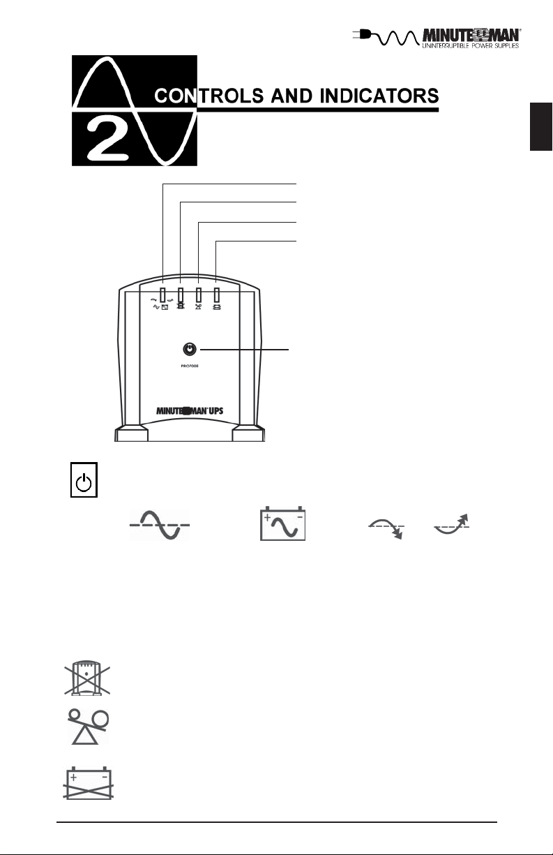
On-Line/On-Battery/Boost/Buck LED
Fault LED
Overload LED
Weak/Bad Battery LED
On/Off/Test Button
Press and release the ON/OFF/Test Button after 1 beep to turn the
UPS ON or OFF (see section 4).
English
On-Line On-Battery Buck Boost
The On-Line/On-Battery/Boost and Buck (green) LED illuminates in a steady
state when the UPS is on and supplying AC power to the load. The LED blinks
and the audible alarm sounds, when supplying battery power to the load. The
LED blinks and no audible alarm when the UPS is in either the boost or the
buck mode.
The Fault (red) LED illuminates when the UPS has detected an internal fault. (see section 5)
The Overload (yellow) LED illuminates when the loads connected to
the UPS exceeds the UPS power rating. (see section 5)
The Weak/Bad Battery (red) LED illuminates when the UPS has
detected that the batteries are Weak/Bad. Battery replacement might
be required. (see section 5)
5
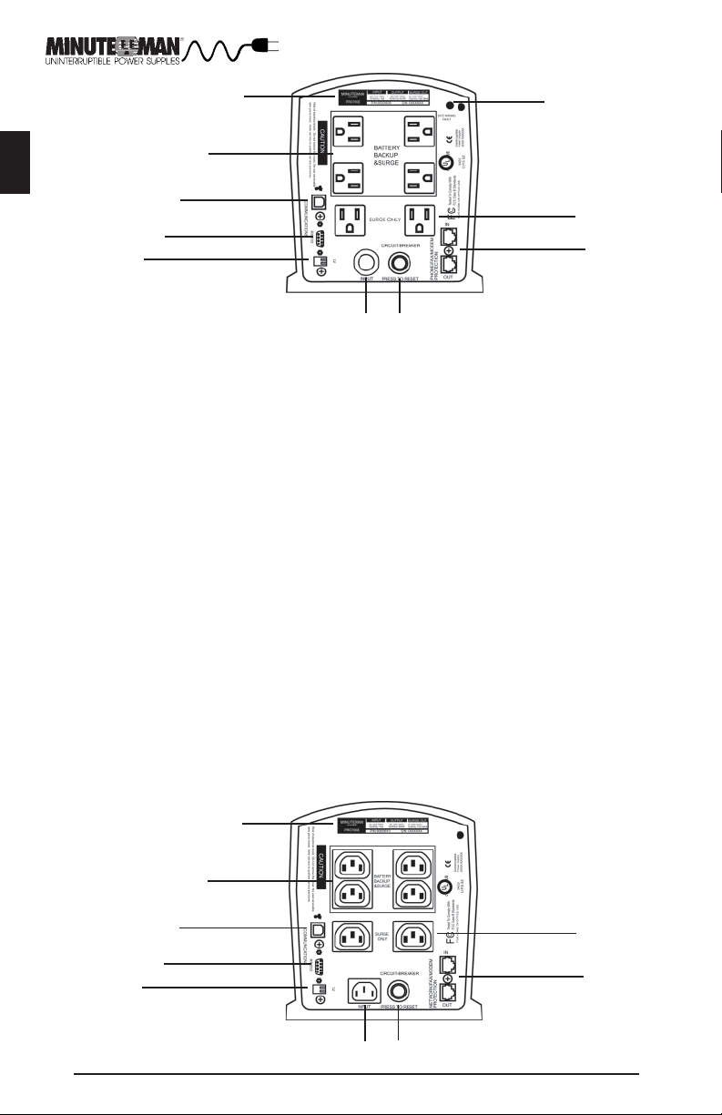
REAR PANEL
English
1
10
2
120V Models
3
4
5
6
7
1. The Information/Rating Label.
2. The Battery Backup and Surge output power receptacles are NEMA 5-15R
type (IEC 320 C13 sockets for 230V models).
3. The USB Communications Interface Port is for UPS monitoring and control.
4. The RS232 Communications Interface Port is for UPS monitoring and
control.
5. The Dipswitches are for setting the Inverter output voltage.
6. The input power cord has a NEMA 5-15P Plug (IEC 320 C14 socket for 230V
models).
7. The input circuit breaker will trip in the event the load exceeds the UPS’s
power rating.
8. The RJ11/RJ45 modular connectors are used for 10 Base-T Network/Fax/
Modem protection.
WARNING: The 230V models are NETWORK PROTECTION ONLY.
9. The Surge ONLY output power receptacles are NEMA 5-15R type (IEC 320
C13 sockets for 230V models).
NOTE: The Surge ONLY output power receptacles are only on the following
models: PRO500E, PRO700E, PRO500iE, PRO700iE.
10. The Site Wiring Fault (SWF) LED illuminates when the UPS detects an
improperly wired AC wall outlet (120V models only).
9
8
230V Models
6
1
2
3
4
5
6
7
9
8
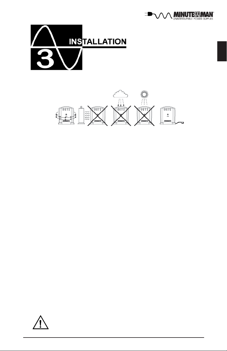
INSTALLATION PLACEMENT
The PRO-E series is intended to be install in a temperature controlled environment that is free of conductive contaminants. Select a location which will provide good air circulation for the UPS at all times. Avoid locations near heating
devices, water or excessive humidity, or where the UPS is exposed to direct
sunlight. Route power cords so they cannot be walked on or damaged.
Operating Temperature (Maximum): 0 to 40 degrees C (+32 to 104 degrees F)
Operating Elevation: 0 to 3,000m (0 to 10,000 ft)
Operating and Storage Relative Humidity: 95%, non-condensing
Storage Temperature: -15 to +45 degrees C (+5 to +113 degrees F)
Storage Elevation: 0 to 15,000m (0 to +50,000 ft)
INSTALLATION
Be sure to read the installation placement and all the cautions before installing
the UPS. Place the UPS in the final desired location and complete the rest of
the installation procedure. USE CAUTION: The UPS is heavy. Use the
appropriate number of personnel when installing the UPS.
English
CONNECTING YOUR EQUIPMENT
Plug the equipment into the output receptacles on the rear panel of the UPS.
Do not use extension cords, adapter plugs, power strips or surge strips on the
output of the UPS. Ensure that you do not exceed the maximum output rating
of the UPS (refer to the UPS's back panel or the Electrical Specifications in this
manual).
CAUTION!
DO NOT connect a laser printer to the output receptacles on the
UPS, unless the UPS is rated 2000VA or greater. A laser printer
draws significantly more power when printing than at idle and
may overload the UPS.
7
 Loading...