

Page 1
ParaShield 1224
User’s Manual
ParaShield 1224 is designed to provide a local power solution for cable
telephony, wireless local loop (WLL), and fiber to the home (FTTH)
broadband equipment.
IMPORTANT SAFETY WARNINGS
This manual contains important instru ctions regarding the installation and
operation of this device. Read this manual thoroughly before attempting to
unpack, install or operate this device
CAUTION! The battery can energize hazardous live parts inside even
when the AC input power is disconnected.
CAUTION! To reduce the risk of electric shock, do not remove the cover,
except to service the battery. No user serviceable parts inside, except for the
battery.
CAUTION! To avoid electric shock, turn off the unit and unplug it from the
AC power source before servicing the battery or installing your equipment.
(SAVE THESE INSTRUCTIONS)
INSTALLATION
(QUALIFIED SERVICE PERSONNEL ONLY)
Please read this manual before installing this DC UPS as it provides important
information that should be followed during the installation and repair of the DC
UPS:
1.) The ParaShield 1224 is intended to be installed in a temperature controlled
environment that is free of conductive contaminants. Select a location which
will provide good air circulation for the DC UPS at all times. Avoid locations
near heating devices, water or excessive humidity, or where the DC UPS is
exposed to direct sunlight. Route power cords so they cannot be walked on
or damaged.
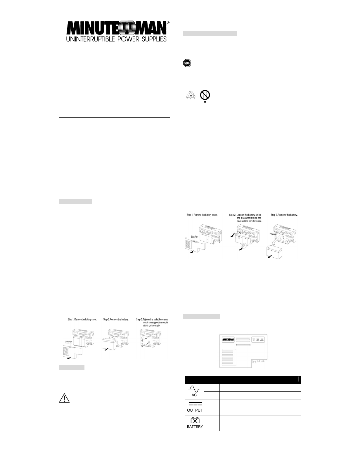
2.) Remove the cover.
3.) Remove the battery.
4.) The wall mount screws must be the appropriate size for total weight of the
UPS and the mounting structural material.
5.) Connect the battery negative (Black) wire to the battery negative terminal.
6.) Connect the battery positive (Red) wire to the battery positive terminal.
7.) Re-install the battery into the ca se.
8.) Connect the output wires and connector to the DC UPS.
9.) Connect the Communications Signal wires to the DC UPS.
10.) Re-install the cover.
11.) See the section “Operation” for the startup procedure.
OPERATION
1.) Plug the DC UPS power cord into the AC inlet on the DC UPS.
2.) Plug the DC UPS power cord into the wall outlet.
3.) Turn on the connected equipment.
4.) The DC UPS is ready for normal operation.
The DC UPS charges the battery when it is connected to utility
power. It is recommended that the battery charge for minimum of
18 hours before use. The DC UPS may be used immediately,
however, the “On Battery“ runtime may be less than normally
expected.
BATTERY REPLACEMENT
(QUALIFIED SERVICE PERSONNEL ONLY)
This DC UPS has a hot-swappable battery. Hot-swappable battery means
that the battery can be replaced without powering down the whole DC UPS
system.
If there is a power interruption while replacing the hot-swappable
battery, with the DC UPS on, the load will not be backed up.
CAUTION!
to the skin and eyes and may be toxic.
CAUTION!
system can still present a risk of electrical shock. The current capability of a
battery is sufficient to burn wire or tools very rapidly, producing molten metal.
Observe these precautions when replacing batteries:
1.) Remove watches, rings, or other metal objects.
2.) Use hand tools with insulated handles.
3.) Wear protective eye gear (goggles), rubber gloves and boots.
4.) Do not lay tools or other metal parts on the top of the batteries.
5.) Disconnect the charging source before connecting or d isconnecting the
battery terminals.
6.) Determine if the battery is inadvertently grounded. If the battery is,
remove the source of the grounding. Contact with any part of a grounded
battery can result in an electrical shock. The likelihood of such shock will be
reduced, if such grounds are removed during installation and maintenance.
Step 4. Connect the black cable to the battery negative terminal on the new
battery.
Step 5. Connect the red cable to the battery positive terminal on the new
battery.
Step 6. Install the new battery into the battery compartment.
Step 7. Tighten the battery stripe to secure the battery.
Step 8. Re-install the battery cover.
Step 9. The DC UPS is ready for normal operation.
Step 10. Dispose of the old battery properly.
Do not open or mutilate batteries. Released electrolyte is harmful
Do not dispose of batteries in a fire. The batteries may
explode. The batteries in this UPS are recyclable.
Dispose of the batteries properly. The batteries contain
lead and pose a hazard to the environment and human
health if not disposed of properly. Refer to local codes
for proper disposal requirements or return the battery to
MINUTEMAN in the packing material for the new
battery.
Although battery system voltages are only 12VDC the battery
Warning Indicator
● Front Panel
Indicator Color Condition
Green DC UPS is on utility power.
Yellow DC UPS is on battery power.
Green DC output power is provided by the battery or
utility power.
Red The battery is not connected or the battery needs
to be replaced.
PN-34000247 Rev0
Page 2
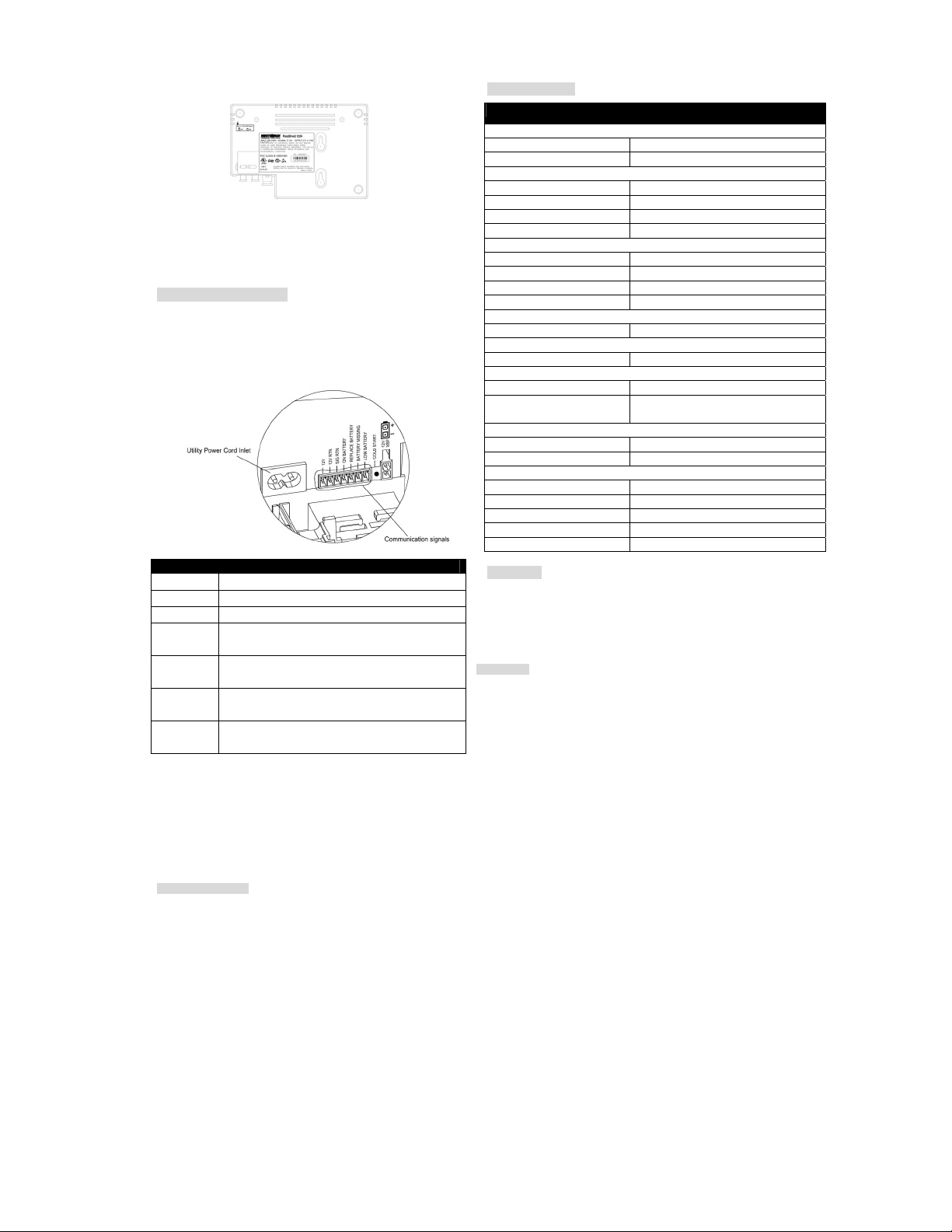
● Back Panel
○ Buzzer On/Off Switch: The default position of the buzzer switch is OFF. If
you want to enable this function, there is a button inside the hole, please
insert a paper clip or small pointed object into the hole and press the button.
In case of utility failure (on battery), it will emit a long beep. In case of low
battery, it will emit a short beep.
Communication Signals
The communication signals of this unit are isolated from the internal circuitry
via open collector Opto-coupled transistors. The connection “SIG RTN”
(Signal Return) is a common return point for all communication signals. In
the typical application, the attached equipment digital ground connects to
Signal Return, and pull-up resistors turn the open collector signals into logic
levels.
Signal Message
12V + Voltage output
12V RTN - Voltage output
SIG RTN Signal return
ON BATTERY Low when operating from utility line.
REPLACE
BATTERY
BATTERY
MISSING
LOW
BATTERY
particular insta llation. If this equipm ent does cause harmf ul interference to radio or television re ception, which can be determined by turning the equipment off and on, the user is
encouraged to try to correct the interference by one or more of the following measures: (1) Reorient or relocate the receiving antenna. (2) Increase the separation between the
equipment and receive r. (3) Connect the equipm ent into an outlet on a circuit different from that to whic h the receiver is connected. (4) Consult the dealer or an experienced radio/TV
technician for help. Any special accessories needed for compliance must be specified in the instruction.
CAUTION: A shielded-type power cord is required in order to meet FCC emission limits and to prevent interference to the nearby radio and television receptio n. It is essent ial that
only the supplied power cord be used. Use only shielded cables to connect I/O devices to this equipment.
CAUTION: Any changes or modifications not expressly approved by MINUTEMAN UPS could void the authority granted by the FCC to operate this equipment. For more information,
please contact: MINUTEMAN UPS: Phone: (800) 238-7272, (972) 446-7363, Fax: (972) 446-9011, www.minutemanups.com
Open when operating from battery.
Low when battery is charged.
Open when battery fails the Self Test.
Low when battery is present.
Open when battery is missing.
Low when battery is near full charge capacity.
Open when operating from a battery with < 20% capacity.
SPECIFICATION
Model ParaShield 1224
Input
Voltage Range 85Vac – 264Vac (Universal Input)
Frequency Range 47 – 70 Hz
Output
On Battery Output Voltage 12VDC
Continuous Power Capability 24Watts
Output Power Max 24Watts
Efficiency (at 75% Load) > 75 %
Battery
Battery Type Sealed, Maintenance Free Lead-Acid Battery
Numbers of Battery 1-12V7.2AH
Typical Recharge Time 18-Hours
Replaceable Yes
Surge Protection and Filtering
Lightning / Surge Protection
Warning Diagnostics
Indicators AC, Output, Battery
Management
Auto-Charge Yes
Communication Interface On Battery, Replace Battery, Battery Missing,
Physical
Net Dimensions (L*W*D) 16.7cm x 24cm x8.1cm
Net Weight (kg) 3.28
Environment
Operating Temperature 32oF – 104oF (0-40oC)
Operating Humidity 0 – 95% noncondensing within enclosure
Max Operating Elevation 10,000ft (3,000m)
Max Storage Elevation 50,000ft (15,000m)
Storage Temperature 5oF – 113oF (-15oC – 45oC)
Cold Start
The cold start feature is for applying power to the DC UPS and connected
equipment when the DC UPS is off and there is no utility power. Before using
the cold start feature, please make sure the battery is charged. To start the
cold start feature, press the recessed cold start button with a small pointed
object.
FCC Notice:
This equipment has been tested and found to comply with the limits for a Class B Digital
Device, pursuant to Part 15 of the FCC Rules. These lim its are designed to provid e
reasonable protec tion against harm ful interference i n residential ins tallation. This
equipment generates uses and can radiate radio frequency energy and, if not installed and
used in accordance with the instructions, may cause harmful interference to radio
communications. However, there is no guarantee that interference will not occur in a
Ye s
Low Battery
LIMITED WARRANTY
Para Systems Inc. (Para Systems) warrants this equipment, when properly applied and operated within specified conditions, against faulty materials (excluding the batteries) or
workmanship for a per iod of three years from the date of orig inal purchase by the end user. Para System s Inc. (Para Systems) warrants the Batteries for a period of two years from the
date of purchase. For equipment sites within the United States and Canada, this warranty covers repair or replacement of defective equipment at the discreti on of Para Systems.
Repair will be from the nearest authorized service center. Replacement parts and warranty labor will be borne by Para Systems. For equipment located outsi de of the United States
and Canada, Para Systems only covers faulty parts. Para Systems products repaired or replaced pursuant to this warranty shall be warranted for the remaining portion of the warranty
that applies to the original product. This warranty applies only to the original purchaser who must have properly registered the product within 10 days of purchase. The warranty shall
be void if (a) the equipment is damaged by the customer, is improperly used, is subjected to an adverse operating environment, or is operated outside the limits of its electrical
specifications; (b) the equipment is repaired or modified by anyone other than Para Systems or Para Systems-approved personnel; or (c) has been used in a manner contrary to t he
product's operating m anual or other written instructions. Any technic al advice furnished before or after delivery in rega rd to use or application of Para Systems’s equi pment is furnished
without charge and on the basis that it represents Para Systems’s best judgment under the circumstances, but it is used at the recipient's sole risk. EXCEPT AS PROVIDED HEREIN,
PARA SYSTEMS MAKES NO WARRANTIES, EXPRESSED OR IMPLIED, INCLUDING WARRANTIES OF MERCHANTABILITY AND FITNESS FOR A PARTICULAR PURPOSE.
Some states do not permit limitation of implied warranties; therefore, the aforesaid limitation(s) may not apply to the purchaser. EXCEPT AS PROVIDED ABOVE, IN NO EVENT WILL
PARA SYSTEMS BE LIABLE FOR DIRECT, INDIRECT, SPECIAL, INCIDENTAL, OR CONSEQUENTIAL DAMAGES ARISING OUT OF THE USE OF THIS PRODUCT, E VEN IF
ADVISED OF THE POSSIBILITY OF SUCH DAMAGE. Specificall y, Para Systems is not liable for any costs, such as lo st profits or revenue, loss of equipment, loss of use of
equipment, loss of software, loss of da ta, cost of substitu tes, claims by thir d parties, or othe rwise. The sole and ex clusive remedy for breach of any warranty, expressed or implied,
concerning Para Systems’s products and the only obligation of Para Systems hereunder, shall be the repair or replacement of defective equipment, components, or parts; or, at Para
Systems’s option, refund of the purchase price or substitution with an equivalent replacement product. This warranty gives you specific legal rights and you may also have other rights,
which vary from state to state.
PN-34000247 Rev0
 Loading...