

Minus Forty 15-UDGF Installation Manual
To better help you obtain assistance or service should you ever need it, write down the
following information about the product. This information is on the identification label
located on the left hand inside wall of the cabinet. We advise you to keep this Owners
Manual and sales slip in your possession.
Model:
Serial Number:
Date of Purchase:
Owners Manual
30 Armstrong Avenue
Georgetown, Ontario
Canada L7G 4R9
Tel: 800.800.5706 or 905.702.1441
Fax: 905.702.1442
Email: info@minusforty.com
Web: www.minusforty.com
MNL_USGF-UDGF-X1_EN150416
Glass Door Freezers
Single and Double Door Models
30 A R MS T R ON G AV E . GE OR G E TO W N, ON TA RI O CA NA D A L7 G 4R9
TEL 800.800.5706 • 905.702.1441 • FAX 905.702.1442 • WWW.MINUSFORTY.COM
Models
09-USGF-X1
09M-USGF-X1
09X-USGF-X1
10-USGF-X1
13-USGF-X1
15-UDGF
15-UDGF-X1
19-USGF-X1
22-USGF-X1
43-UDGF-X1
44-UDGF-X1
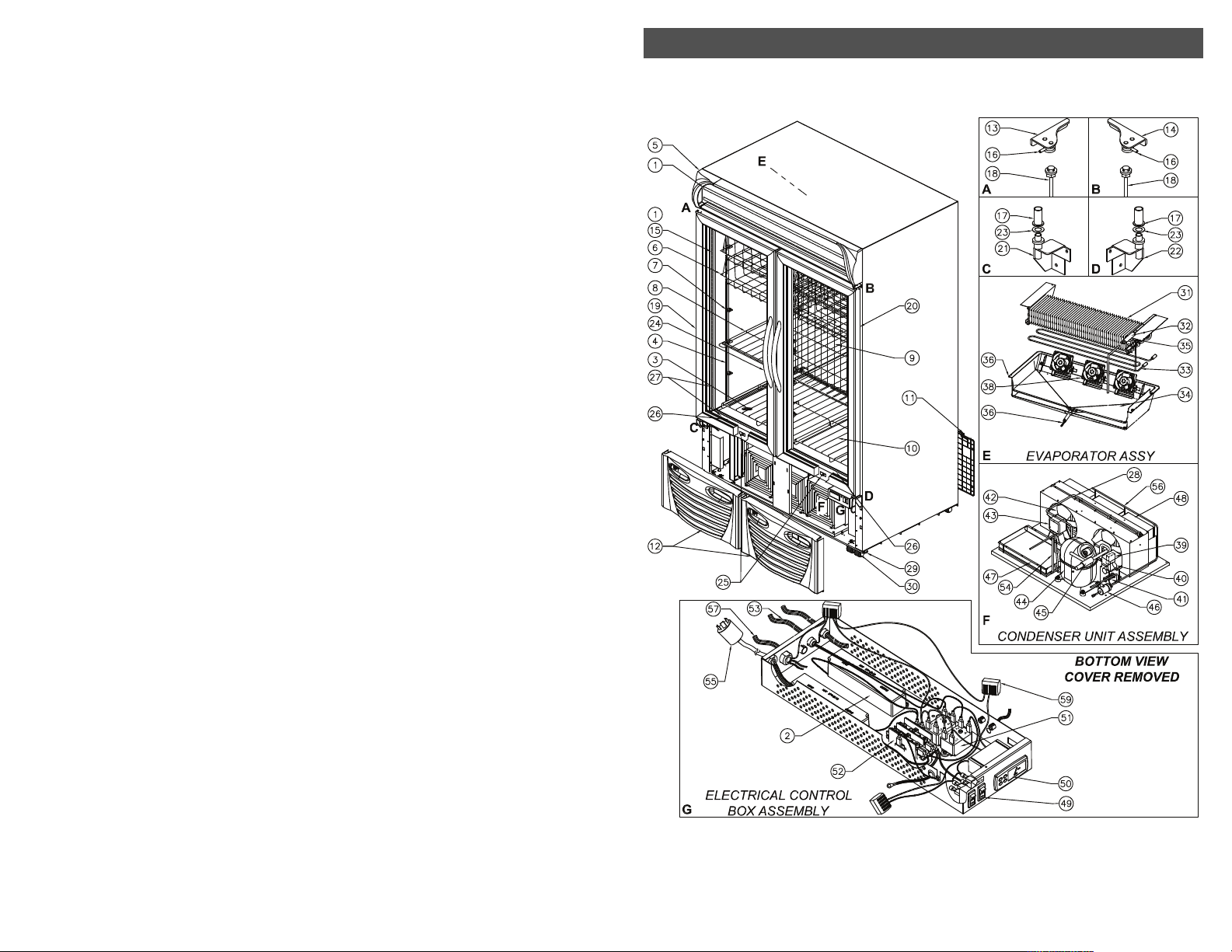
ILLUSTRATION: 43-UDGF-X1, 44-UDGF-X1
23
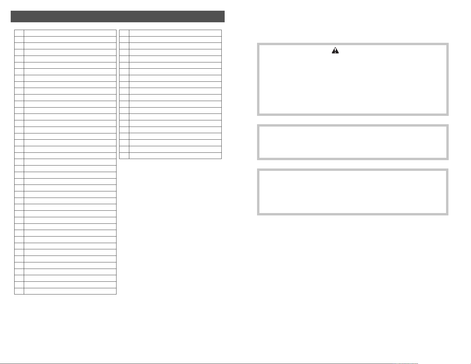
PARTS LIST: 43-UDGF-X1, 44-UDGF-X1
No. Description
1 LED Strip
2 LED Driver
3 Pressure Relief Ball
4 Pilaster
5 Top Display Assembly
6 Basket
7 Pilaster Clip
8 Shelf
9 Interior Back Grill
10 Bottom Shelf
11 Rear Grill
12 Front Bottom Grill
13 Door Top Bracket (Left)
14 Door Top Bracket (Right)
15 Heater Breaker Seal LED
16 Torsion Pin
17 Bushing, Nylon (c/w Door)
18 Torsion Bar (c/w Door)
19 Door Assembly (Left)
20 Door Assembly (Right)
21 Door Bottom Bracket (Left)
22 Door Bottom Bracket (Right)
23 Nylon Washer
24 Door Handle
25 Door Switch
26 Cabinet Anti-Condensate Heater
27 Heater Breaker Seal (Bottom/Top)
28 Discharge Header
29 Leveling Leg
30 Caster
31 Evaporator Coil
32 Suction Accumulator
33 Defrost Heater
34 Evaporator Tray
35 Thermostat, Defrost Limit
36 Drain Tube Heater
37 Evaporator Shroud
38 Evaporator Fan
39 Relay Potential
40 Run Capacitor
No Description
41 Start Capacitor
42 Fan Blade (Condensing Unit)
43 Fan Motor (Condensing Unit)
44 Compressor
45 CPR Valve
46 Filter Drier
47 Condensate Tray
48 Condenser Coil
49 Rocker Switch
50 Controller
51 Defrost Relay
52 Compressor Contactor
53 Defrost Heater/Evaporator Fan Wires
54 Compressor Discharge Line
55 Power Cord
56 Liquid Header
57 Compressor Harness
58 3 Pole Terminal Block
59 5 Pole Terminal Block
WARNING
MAKE SURE THE FREEZER IS DISCONNECTED FROM THE POWER
SUPPLY BEFORE ANY SERVICE. PRESS THE FREEZER SWITCH TO
THE “OFF” POSITION THEN UNPLUG THE POWER CORD FROM THE
ELECTRICAL RECEPTACLE.
ALL SERVICE WORK MUST BE PERFORMED BY A CERTIFIED
TECHNICIAN ONLY.
IMPORTANT
READ ALL INSTRUCTIONS
SAVE THESE INSTRUCTIONS FOR FUTURE REFERENCE
NOTICE
OPERATING THE FREEZER FOR 24 HOURS PRIOR TO LOADING
PRODUCT IS RECOMMENDED
MONITOR FREEZER TEMPERATURE REGULARLY
22
CONTENTS
ILLUSTRATION: 15-UDGF-X1, 15-UDGF
Warranty
Installation Instructions
Shelf and Basket, Placement and Adjustment
Operating Instructions
Product Loading
Temperature Adjustment and Switch Functions
Controller Alarms and Signals
Controller Symbols and Functions
Manual Defrost
How to Remove the Front Bottom Grill
Cleaning
Condenser Cleaning
ISD Trans-Light LED Strip Replacement
Interior LED Strip Replacement
Troubleshooting Guide
1
2
3
3
4
5
5 - 6
6
7
7
8
9
10
11
12 - 13
15-UDGF-X1
15-UDGF
Wiring Diagrams
Parts List
(09/09M/09X/10-USGF-X1)
Illustration (09/09M/09X/10-USGF-X1)
Parts List (13/19/22-USGF-X1)
Illustration (13/19/22-USGF-X1)
Parts List (15-UDGF-X1, 15-UDGF)
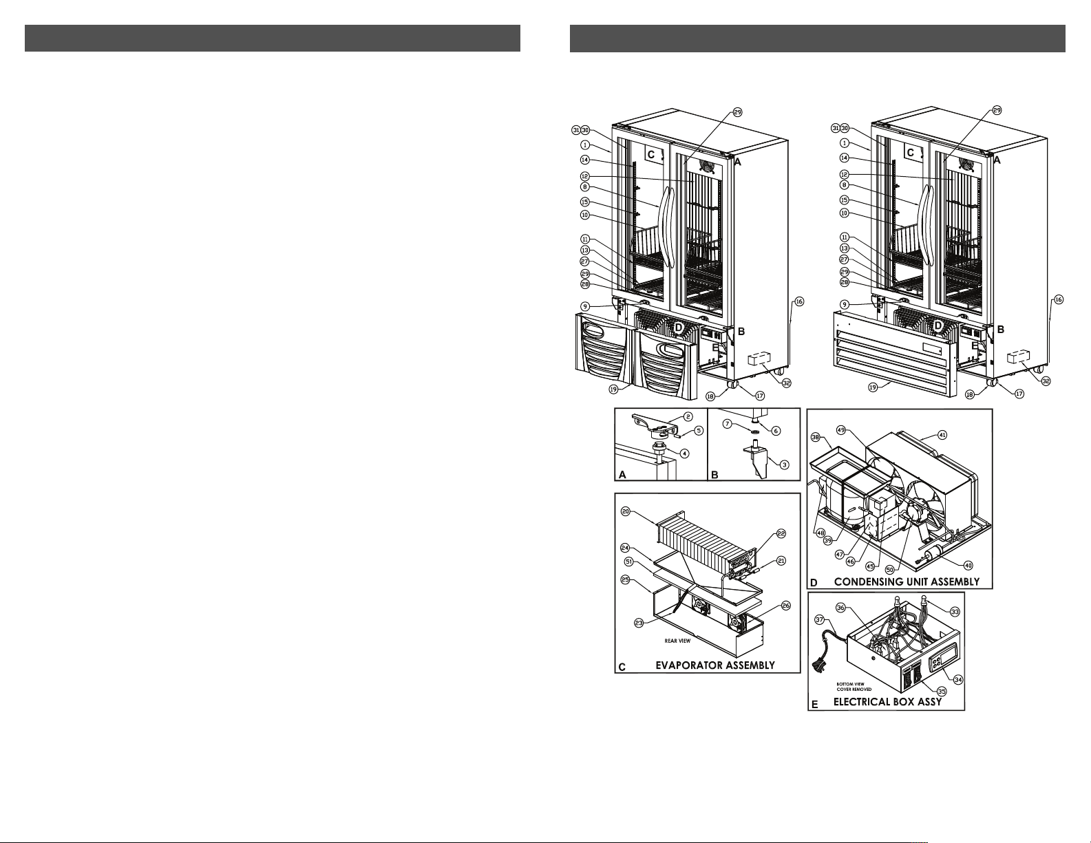
Illustration (15-UDGF-X1, 15-UDGF)
Parts List (43/44-UDGF-X1)
Illustration (43/44-UDGF-X1)
14 - 15
16
17
18
19
20
21
22
23
21
PARTS LIST: 15-UDGF-X1, 15-UDGF
No Description
1 Door (Right or Left Hand)
2 Door Top Bracket (Right or Left)
3 Door Bottom Bracket (Right or Left)
4 Torsion Bar
5 Tension Pin
6 Bushing
7 Nylon Washer
8 Door Handle
9 Door Switch
10 Basket
11 Shelf
12 Interior Back Grill
13 Bottom Shelf
14 Pilaster
15 Pilaster Clip
16 Rear Grill
17 Leveling Leg
18 Caster
19 Front Bottom Grill
20 Evaporator Coil
21 Defrost Heater
22 Suction Accumulator
23 Drain Tube Heater
24 Evaporator Tray
25 Evaporator Shroud
26 Evaporator Fan
27 Evaporator Styrofoam Pad
28 Cabinet Anti-Condensate Heater
29 Heater Breaker Seal (Side and Bottom/Top)
30 Heater Breaker Seal (LED)
31 LED STRIP
32 LED Driver (Interior Light)
33 Bell Connector
34 Controller
35 Rocker Switch
36 Compressor Relay
No Description
37 Power Cord
38 Condensate Tray Assembly
39 Compressor
40 Filter Drier
41 Condenser Coil
42 not used
43 not used
44 not used
45 Start Relay
46 Start Capacitor
47 Run Capacitor
48 Overload Protector
49 Fan Blade(Condensing Unit)
50 Fan Motor(Condensing Unit)
51 Thermostat, Defrost Limit
STANDARD WARRANTY FOR MINUS FORTY
®
REFRIGERATION EQUIPMENT AND ACCESSORIES
LIMITED WARRANTY
Minus Forty®Technologies Corp. warrants its products to be free from defect as
to workmanship and materials for a period of twelve (12) months from the time
of delivery.
Minus Forty
fective parts returned within twelve (12) months of the time of delivery, transportation charges prepaid, which Minus Forty
discretion, determines to be defective.
This warranty shall not apply to any products that have been repaired or altered
outside of Minus Forty
pairs in the judgement of Minus Forty
ability or wear of the product and nor does the guarantee apply to any product
which has been subject to misuse, accident or to any product which has not been
maintained pursuant to the instruction of Minus Forty
This warranty does not extend to any consequential damage caused by the failure
of the product under any circumstance and further, Minus Forty
Corp. shall not be responsible for damage to the contents of the product or any
economic loss caused by the failure of the product, whether such loss is suffered
by the customer or a third party user of the product or whether the contents are
owned by the customer or a third party user or supplier.
Effective January 1, 1996
®
Technologies Corp. will at its option either replace or repair any de-
®
Technologies Corp. in its sole
®
Technologies Corp.’s factory or repair facilities if the re-
®
Technologies Corp. have affected the reli-
®
Technologies Corp.
®
Technologies
20
1
 Loading...